


INSTALLATION MANUAL
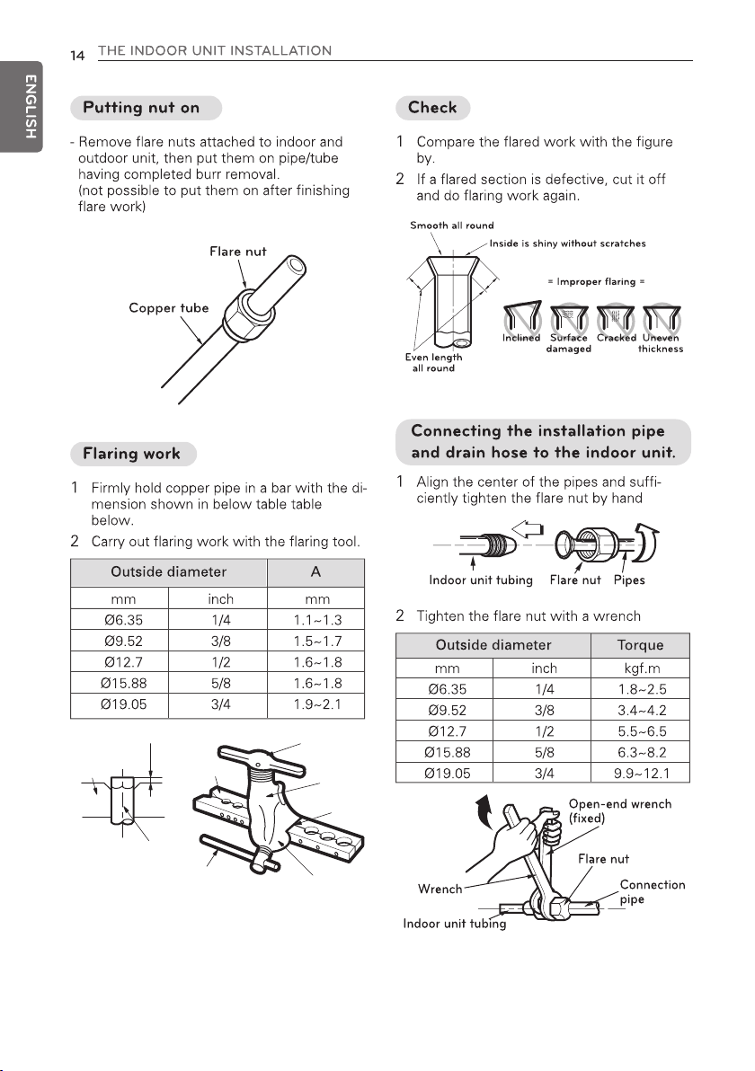
AIR
CONDITIONER
ENGLISH
ESPAÑOL
PORTUGUÊS
Please read this installation manual completely before install-
ing the product.
Installation work must be performed in accordance with the
national wiring standards by authorized personnel only.
please retain this installation manual for future reference after
reading it thoroughly
Ceiling Suspended Air Conditioner
Original instruction
Models:
ARNU18GV1A4 ARNU24GV1A4 ARNU36GV2A4 ARNU48GV2A4
P/NO : MFL67107614
REV.01_021517
www.lg.com

2
TIPS FOR SAVING ENERGY
ENGLISH
• Do not cool excessively indoors. This may be harmful for your health and may consume more
electricity.
• Block sunlight with blinds or curtains while you are operating the air conditioner.
• Keep doors or windows closed tightly while you are operating the air conditioner.
• Adjust the direction of the air flow vertically or horizontally to circulate indoor air.
• Speed up the fan to cool or warm indoor air quickly, in a short period of time.
• Open windows regularly for ventilation as the indoor air quality may deteriorate if the air conditioner is used for many hours.
• Clean the air filter once every 2 weeks. Dust and impurities collected in the air filter may block the
air flow or weaken the cooling / dehumidifying functions.
For your records
Staple your receipt to this page in case you need it to prove the date of purchase or for warranty
purposes. Write the model number and the serial number here:
Model number :
Serial number :
You can find them on a label on the side of each unit.
Dealer’s name :
Date of purchase :
Here are some tips that will help you minimize the power consumption when you use the air
conditioner. You can use your air conditioner more efficiently by referring to the instructions
below:
TIPS FOR SAVING ENERGY

IMPORTANT SAFETY INSTRUCTIONS
3
ENGLISH
IMPORTANT SAFETY INSTRUCTIONS
READ ALL INSTRUCTIONS BEFORE USING THE APPLIANCE.
Always comply with the following precautions to avoid dangerous situations and ensure peak
performance of your product
WARNING
It can result in serious injury or death when the directions are ignored
CAUTION
It can result in minor injury or product damage when the directions are ignored
WARNING
• Installation or repairs made by unqualified persons can result in hazards to you and others.
• Installation MUST conform with local building codes.
• The information contained in the manual is intended for use by a qualified service technician
familiar with safety procedures and equipped with the proper tools and test instruments.
• Failure to carefully read and follow all instructions in this manual can result in equipment malfunction, property damage, personal injury and/or death.
Installation
• Don’t use a power cord, a plug or a loose socket which is damaged.
- Otherwise, it may cause a fire or electrical shock.
• For electrical work, contact the dealer, seller, a qualified electrician, or an Authorized Service Center.
- Do not disassemble or repair the product. There is risk of fire or electric shock.
• Always ground the product.
- There is risk of fire or electric shock.
• Install the panel and the cover of control box securely.
- There is risk of fire or electric shock.
• Always install a dedicated circuit and breaker.
- Improper wiring or installation may cause fire or electric shock.
• Use the correctly rated breaker or fuse.
- There is risk of fire or electric shock.
• Do not modify or extend the power cable.
- There is risk of fire or electric shock.
• Do not let the air conditioner run for a long time when the humidity is very high and a door or a window is left open.
- Moisture may condense and wet or damage furniture.
• Be cautious when unpacking and installing the product.
- Sharp edges could cause injury. Be especially careful of the case edges and the fins on the con-
denser and evaporator.
• For installation, always contact the dealer or an Authorized Service Center.
- There is risk of fire, electric shock, explosion, or injury.
!
!
!

4
IMPORTANT SAFETY INSTRUCTIONS
ENGLISH
• Do not install the product on a defective installation stand.
- It may cause injury, accident, or damage to the product.
• Be sure the installation area does not deteriorate with age.
- If the base collapses, the air conditioner could fall with it, causing property damage, product failure,
and personal injury.
• There is a risk of fire and explosion.
- Inert gas (nitrogen) should be used when you check plumbing leaks, cleaning or repairs of pipes
etc.
If you are using combustible gases including oxygen, product may have the risk of fires and explosions.
• Use a vacuum pump or Inert (nitrogen) gas when doing leakage test or air purge. Do not compress
air or Oxygen and do not use Flammable gases. Otherwise, it may cause fire or explosion.
- There is the risk of death, injury, fire or explosion.
Operation
• Do not store or use flammable gas or combustibles near the product.
- There is risk of fire or failure of product.
CAUTION
Installation
• Always check for gas (refrigerant) leakage after installation or repair of product.
- Low refrigerant levels may cause failure of product.
• Install the drain hose to ensure that water is drained away properly.
- A bad connection may cause water leakage.
• Keep level even when installing the product.
- To avoid vibration or water leakage.
• Use two or more people to lift and transport the product.
- Avoid personal injury.
!

TABLE OF CONTENTS
5
ENGLISH
2 TIPS FOR SAVING EN-
ERGY
3 IMPORTANT SAFETY IN-
STRUCTIONS
6 PRODUCT PARTS
6 INSTALLATION TOOLS
7 INSTALLATION
7 Select the best Location
8 THE INDOOR UNIT IN-
STALLATION
9 Open side-cover
10 Mounting the anchor nut and bolt
12 Indoor unit drain piping
12 Drain piping
12 Drain test
13 Heat insulation
13 Flaring Work
16 Wiring Connection
17 DIP Switch Setting
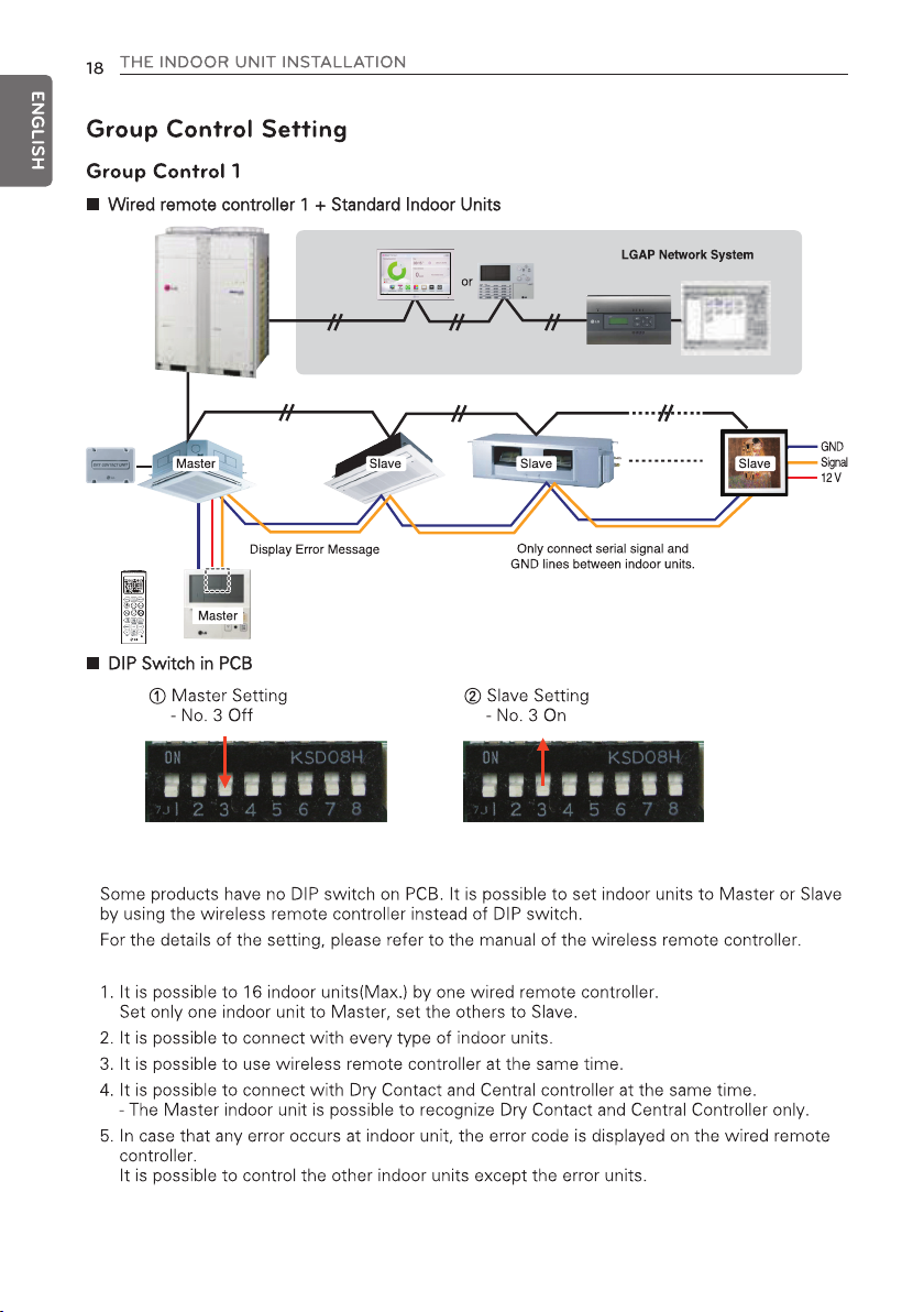
18 Group Control Setting
23 Model Designation
23 Airborne Noise Emission
23 Limiting concentration
TABLE OF CONTENTS
6
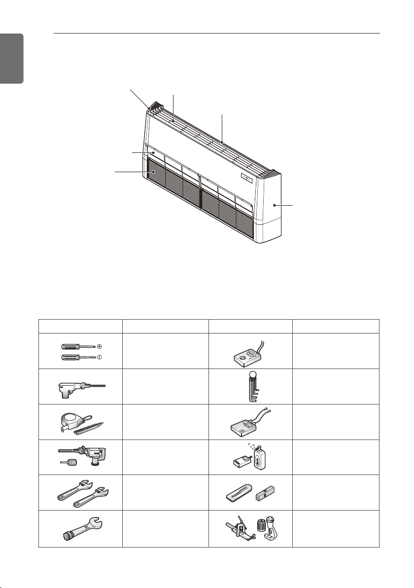
PRODUCT PARTS
ENGLISH
PRODUCT PARTS
INSTALLATION TOOLS
Right side cover
Air filters
(behind inlet grille)
Air inlet vent
(inlet grille)
Louver
Figure FigureName
Screw driver
Air outlet vent
Left side cover
Name
Multi-meter
Electric drill
Measuring tape, Knife
Hole core drill
Spanner
Torque wrench
Hexagonal wrench
Ammeter
Gas-leak detector
Thermometer,
Level
Flaring tool set
INSTALLATION MAP
7
ENGLISH
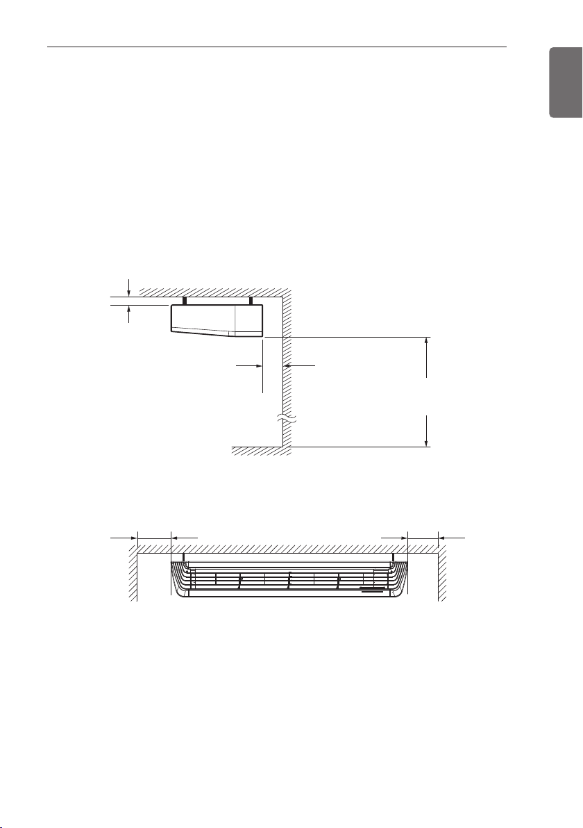
INSTALLATION
Select the best Location
- There should not be any heat source or steam near the unit.
- There should not be any obstacles to prevent the air circulation.
- A place where air circulation in the room will be good.
- A place where drainage can be easily obtained.
- A place where noise prevention is taken into consideration.
- Do not install the unit near the door way.
- Ensure the spaces indicated by arrows from the wall, ceiling, or other obstacles.
- The indoor unit must keep the maintenance space.
10 (13/32)
or more
300 (11 – 13/16)
or more
2500 (98 – 3/7)
or more
700(27 – 9/16) or more
Floor
700(27 – 9/16) or more
unit:mm(inch)
8
THE INDOOR UNIT INSTALLATION
ENGLISH
THE INDOOR UNIT INSTALLATION
• Install the unit horizontally using a level
gauge.
• During the installation, care should be
taken not to damage electric wires.
• Select and mark the position for fixing
bolts and piping hole.
• Decide the position for fixing bolts
slightly tilted to the drain direction after
considering the direction of drain hose.
• Drill the hole for anchor bolt on the ceiling.
CAUTION
!
NOTE
!
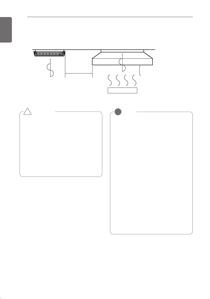
• Avoid the following installation location.
1. Such places as restaurants and kitchen
where considerable amount of oil
steam and flour is generated.
These may cause heat exchange efficiency reduction, or water drops, drain
pump mal-function.
In these cases, take the following actions;
• Make sure that ventilation fan is enough
to cover all noxious gases from this
place.
• Ensure enough distance from the cook-
ing room to install the air conditioner in
such a place where it may not suck oily
steam.
2. Avoid installng air conditioner in such
places where cooking oil or iron powder is generated.
3. Avoid places where inflammable gas is
generated.
4. Avoid place where noxious gas is generated.
5. Avoid places near high frequency generators.
Air conditioner
Take enough
distance
Cooking table
Use the ventilation fan
for smoke-collecting
hood with sufficient
capacity.
THE INDOOR UNIT INSTALLATION
9
ENGLISH
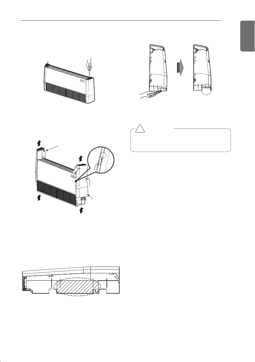
Open side-cover
Step 1
Backside
Right side cover
Backside
Left side
cover
Step 2
- Remove two screws from side-cover.
Step 3
Step 4
- Remove paper bracket from side-cover.
- Unlock side-cover from side-panel slightly
(Tap the side-cover with your palm on the
backside)
- Knock out the pipe hole from the left sidecover with nipper/plier.
Hold the side-cover with other hand while
tapping to prevent it to fall down.
CAUTION
!
10
THE INDOOR UNIT INSTALLATION
ENGLISH
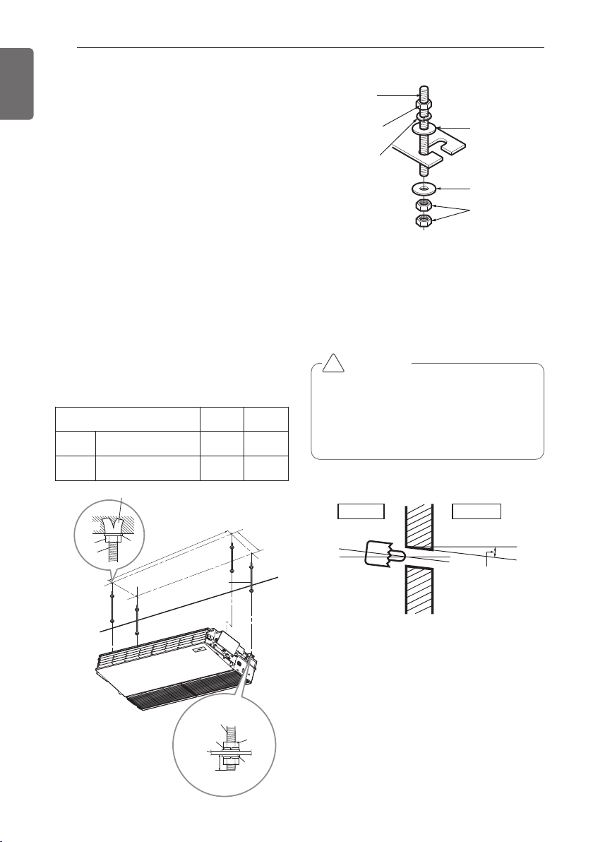
Mounting the anchor nut and
bolt
- Prepare 4 suspension bolts. (Each bolts
length should be same.)
- Measure and mark the position for the
Suspension bolts and the piping hole.
- Drill the hole for anchor nut on the ceiling.
- Insert the nuts and washer onto the suspension bolts for locking the suspension bolts on
the ceiling.
- Mount the suspension bolts to the anchornuts firmly.
- Secure the hangers onto the Suspension
bolts (adjust level roughly.) using nuts, washers and spring washers.
- Adjust a level with a level gauge on the
direction of left-right, back-forth by adjusting
suspension bolts.
- Adjust a level on the direction of top-bottom
by adjusting supension bolts. Then the unit
will be declined to the bottomside so as to
drain well.
- The following parts is option.
Hanging Bolt - W 3/8 or M10
Nut - W 3/8 or M10
Spring Washer - M10
Plate Washer - M10
(Unit : mm)
Washer
Suspension
bolts
Chassis Code A B
VM1 ARNU**GV1A4 1018 355
VM2 ARNU**GV2A4 1418 355
Tighten the nut and bolt to prevent unit
from falling
• Drill the piping hole on the wall slightly
tilted to the outdoor side by using a
Ø 70 hole-core drill.
CAUTION
!
Anchor nut
Ceiling
Nut
Suspension
Suspension
bolts
bolts
Washer
Washer
A
Suspension bolt
B
Hanging bolt
(W3/8 or M10)
Nut
(W3/8 or M10)
Spring washer
(M10)
Flat washer
for M10
(accessory)
Flat washer
for M10
(accessory)
Nut
(W3/8 or M10)
Wall
Indoor
Outdoor
Slope gradient for
drain Should be
1/50 ~ 1/100
Spring
washer
Hangen
12mm
Suspension
bolts
Max.
Nut
Washer
THE INDOOR UNIT INSTALLATION
11
ENGLISH
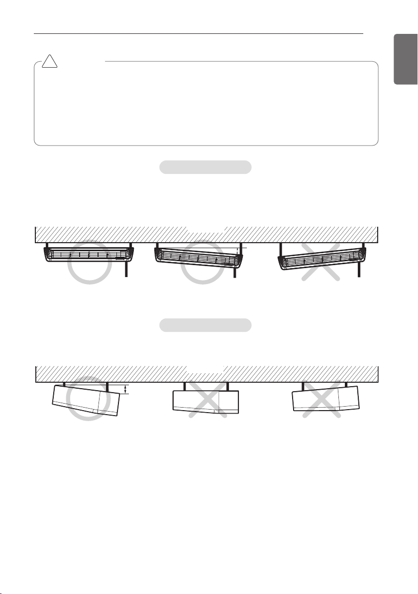
Installation information for declination
- Install declination of the indoor unit is very important for the drain of the convertible type air
conditioner.
- Minimum thickness of the insulation for the connecting pipe shall be 10 mm.
- If the Installation Plates are fixed to horizontal line, the indoor unit after installing will be declined to the bottomside.
CAUTION
!
Front of view
- The unit must be horizontal or inclined at angle.
- The inclination should be less than or equal to 1° or in between 10 to 20 mm inclined in drain
direction as shown in fig.
Ceiling
10~20 mm
Side of view
- The unit must be inclined to the bottomside of the unit when finished installation.
Ceiling
5~10 mm
12
THE INDOOR UNIT INSTALLATION
ENGLISH
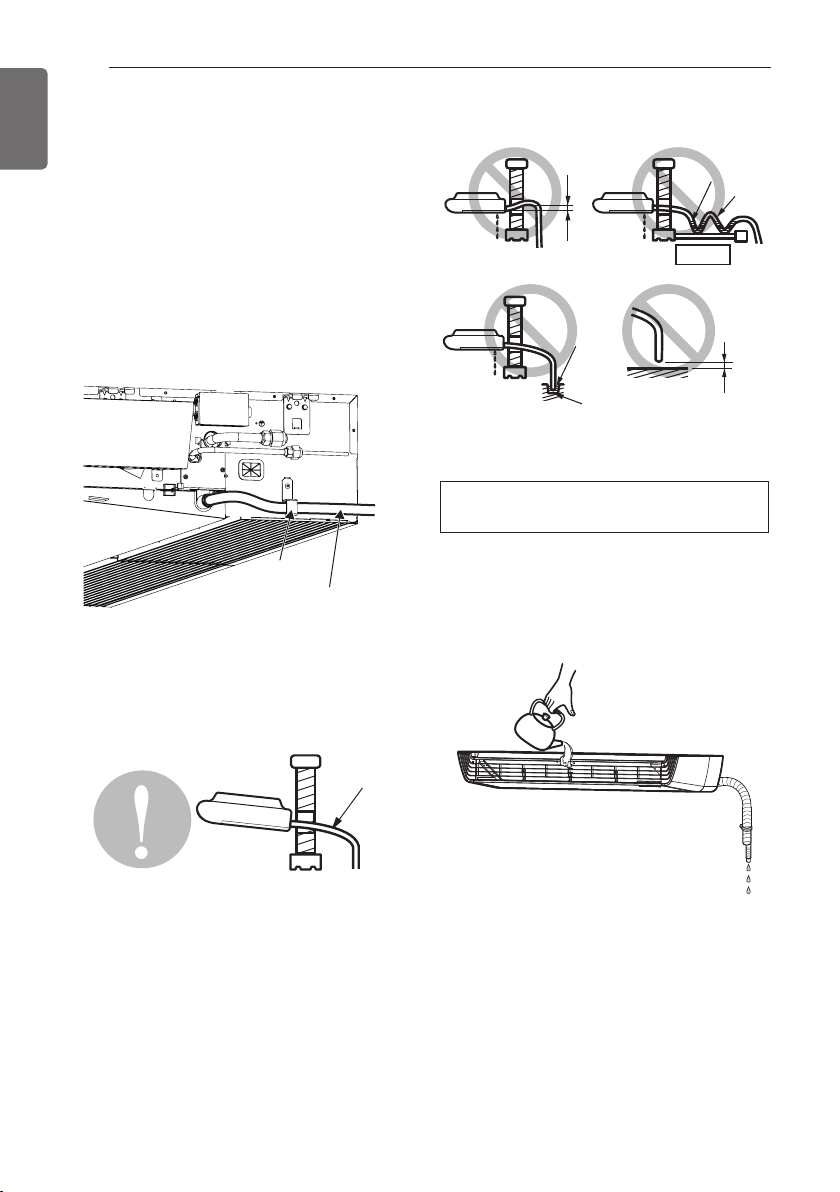
Indoor unit drain piping
- Drain piping must have down-slope (1/50 to
1/100): be sure not to provide up-and-down
slope to prevent reversal flow.
- During drain piping connection, be careful
not to exert extra force on the drain port on
the indoor unit.
- Remove the rubber stopple before connecting drain hose.
- Hook on the bracket after connecting the
drain hose as below.
Drain piping
- The drain hose should point downward for
easy drain flow.
- Do not make drain piping like the following.
- Be sure to execute heat insulation on the
drain piping.
Drain test
Use the following procedure to test the drain
pump operation:
- Set the air direction louvers up-and-down to
the position(horizontally) by hand.
- Pour a glass of water on the evaporator
using a kettle.
- Ensure the water flows through the drain
hose of the indoor unit without any leakage
and goes out the drain exit.
Drain hose
Bracket
Heat insulation material: Polyethylene foam
with thickness more than 8 mm.
Do not raise
Water
leakage
Tip of drain
hose dipped
in water
Water
leakage
Water
leakage
Ditch
Accumulated
drain water
Air
Waving
Less than
50 mm gap
Downward
slope
THE INDOOR UNIT INSTALLATION
13
ENGLISH
Heat insulation
Use the heat insulation material for the refrigerant piping which has an excellent heat-resistance (over 120 °C).
Precautions in high humidity circumstance:
This air conditioner has been tested according
to the "KS Standard Conditions with Mist" and
confirmed that there is not any default.
However, if it is operated for a long time in
high humid atmosphere (dew point temperature: more than 23 °C), water drops are liable
to fall. In this case, add heat insulation material according to the following procedure:
- Heat insulation material to be prepared...
Adiabatic glass wool with thickness 10 to 20
mm.
- Stick glass wool on all air conditioners that
are located in ceiling atmosphere.
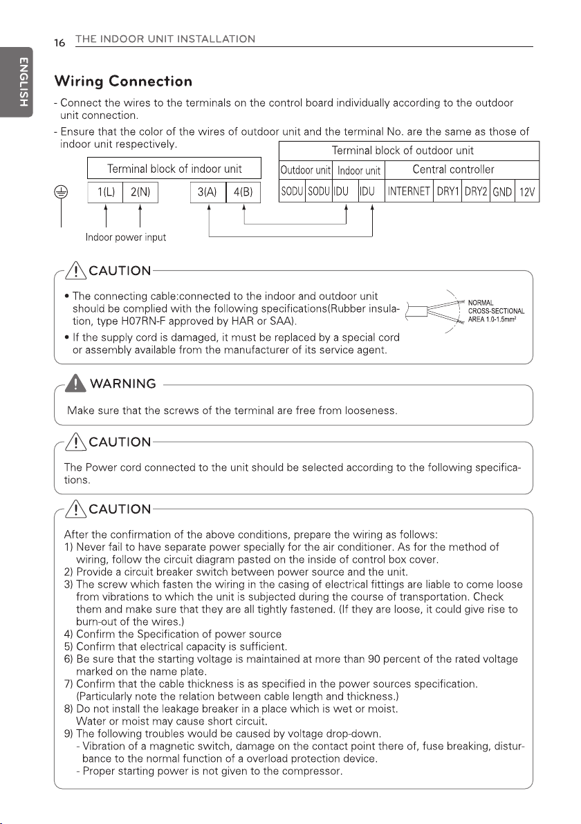
Connecting cables to the indoor unit
- Remove the control box cover for electrical
connection between the indoor and out door
unit
- Use the cord clamper to fix the cord.
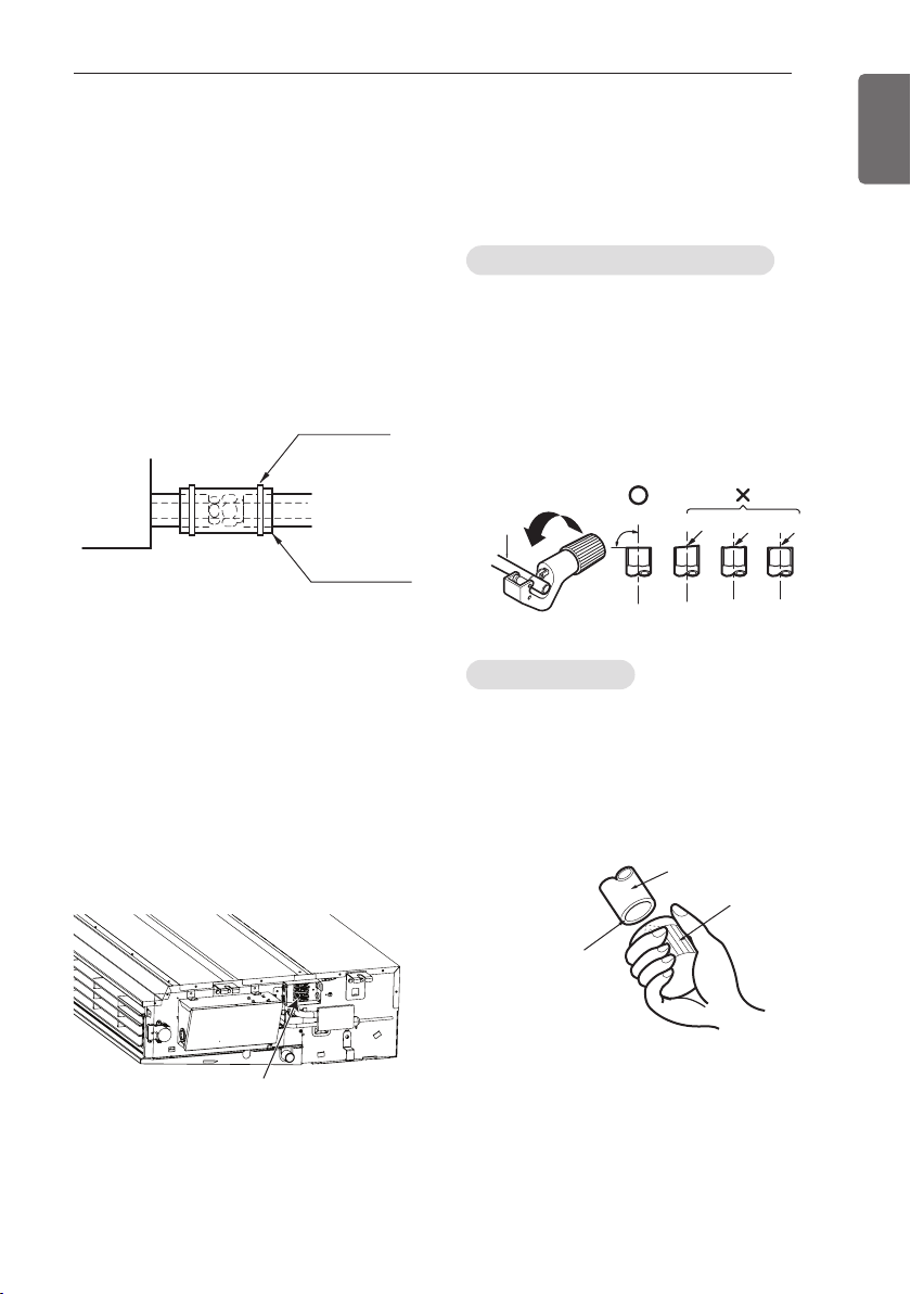
Flaring Work
Main cause for gas leakage is due to defect of
flaring work. Carry out correct flaring work in
the following procedure.
1 Use the piping kit accessory or the pipes
purchased locally.
2 Measure the distance between the indoor
and the outdoor unit.
3 Cut the pipes a little longer than measured
distance.
4 Cut the cable 1.5m longer than the pipe
length.
1. Completely remove all burrs from the cut
cross section of pipe/tube.
2. While removing burrs put the end of the
copper tube/pipe in a downward direction
while removing burrs location is also
changed in order to avoid dropping burrs
into the tubing.
Control box cover
Cut the pipes and the cable
Burrs removal
Pipe
Reamer
Point down
Fastening band
Refrigerant piping
Indoor unit
Thermal insulator
Copper
pipe
90°
Slanted Uneven Rough
Bar
"A"
Copper pipe
Clamp handle
Handle
Bar
Yoke
Cone
Red arrow mark
THE INDOOR UNIT INSTALLATION
15
ENGLISH
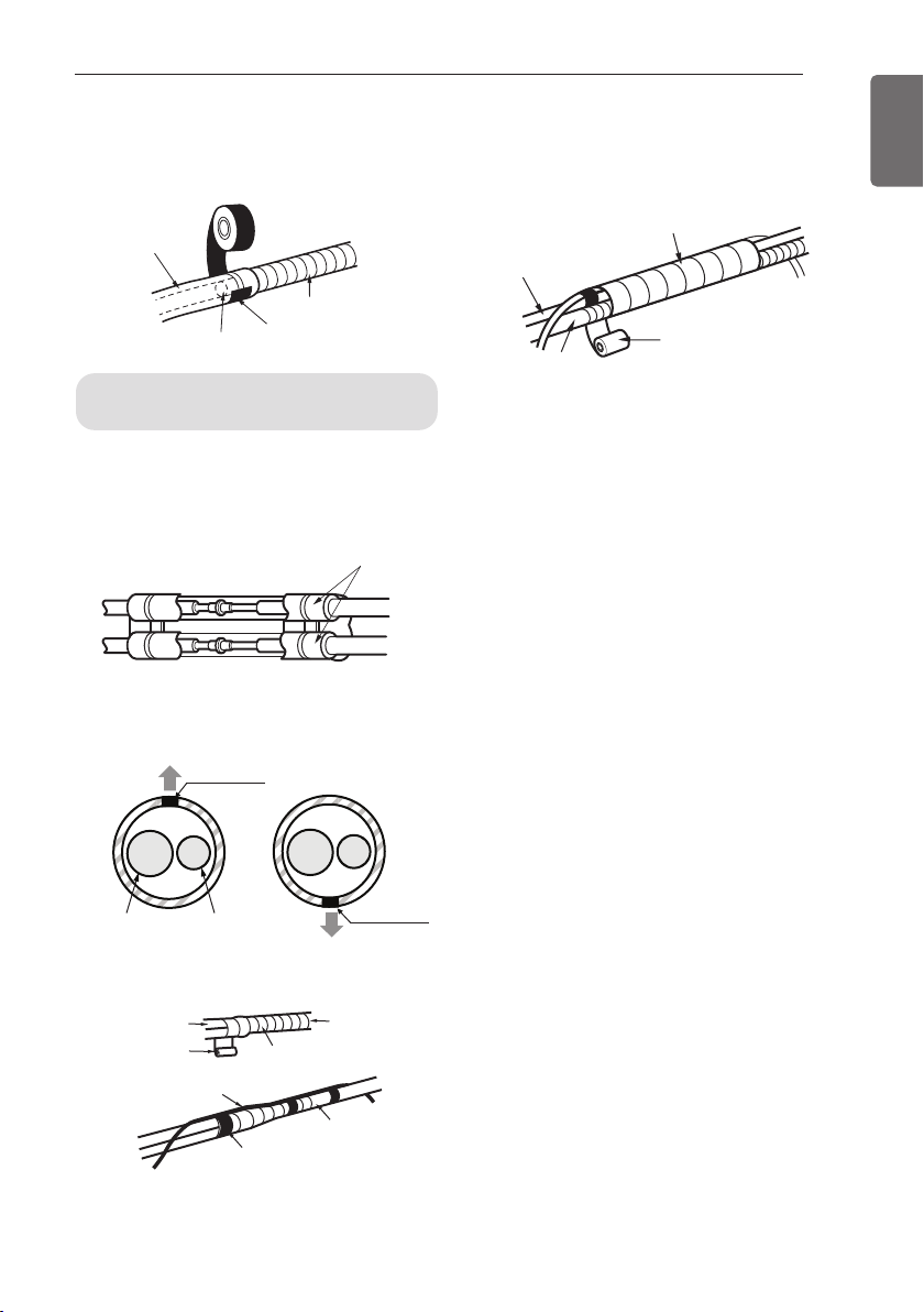
3 When needed to extend the drain hose of
indoor unit, assembly the drain pipe as
shown on the drawing
1 Overlap the connection pipe insulation ma-
terial and the indoor unit pipe insulation
material. Bind them together with vinyl
tape so that there may be no gap.
2 Set the tubing cutting line upward.
Wrap the area which accommodates the
rear piping housing section with vinyl tape.
3 Bundle the piping and drain hose together
by wrapping them with vinyl tape sufficient
enough to cover where they fit into the
rear piping housing section.
Wrap the insulation material
around the connecting portion.
Gas Pipe
Liquid Pipe
Cutting Line
Cutting Line
Good Case Bad Case
* Tubing cutting line have to be upward.
Vinyl tape(narrow)
Connection pipe
Connecting cable
Vinyl tape (wide)
Wrap with vinyl tape
Indoor unit pipe
Pipe
Drain pipe
Indoor unit drain hose
Vinyl tape(narrow)
Adhesive
Insulation material
Wrap with vinyl tape
Pipe
Vinyl tape(wide)
Drain hose
-B -A
17
ENGLISH
THE INDOOR UNIT INSTALLATION
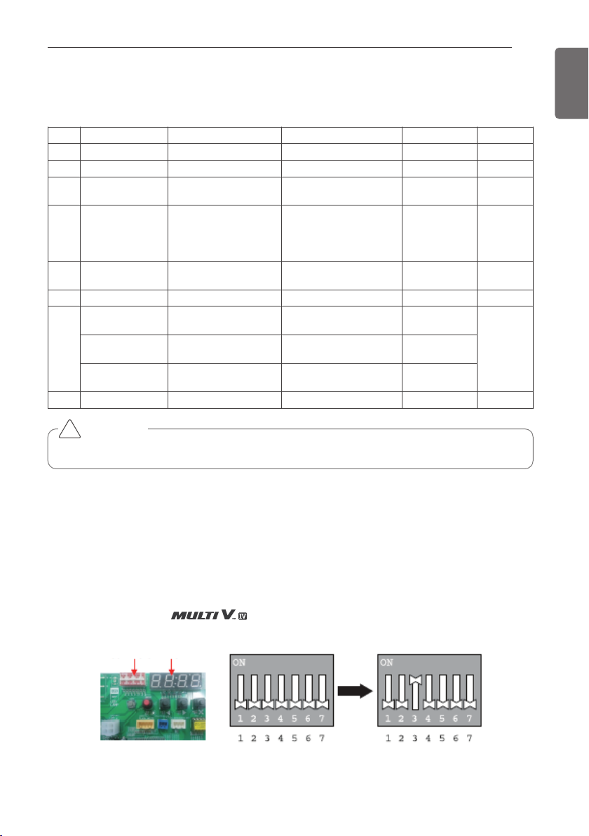
DIP Switch Setting
Indoor Unit
Outdoor Unit
In case that the products meet specific conditions, “Auto addressing” function can start automatically with the improved speed by turning the DIP switch #3 of the outdoor unit and resetting the
power.
* Specific conditions:
- All names of the indoor units are ARNU******4
- The serial number of (outdoor units) should be after October 2013.
CAUTION
For Multi V Models, DIP switch 1, 2, 6, 8 must be set OFF.
!
Function Description Setting Off Setting On Default
SW1 Communication N/A (Default) - - Off
SW2 Cycle N/A (Default) - - Off
SW3 Group Control
Selection of Master
or Slave
Master Slave Off
SW4
Dry Contact
Mode
Selection of Dry Contact Mode
Wired/Wireless remote
controller
Selection of Manual or
Auto operation Mode
Auto
Off
SW5 Position
Selection of installation position
Ceiling Bottom Off
SW6 Heater linkage N/A - - Off
SW7
Ventilator linkage
Selection of Ventilator linkage
Linkage Removal
Working
Off
Vane selection
(Console)
Selection of up/down
side Vane
Up side + Down side
Vane
Up side Vane
Only
Region selection
Selection tropical region
General model Tropical model
SW8 Etc. Spare - - Off
Outdoor Unit PCB Outdoor Unit DIP Switch
DIP switch 7 segment
19
ENGLISH
THE INDOOR UNIT INSTALLATION
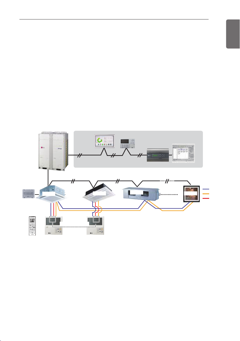
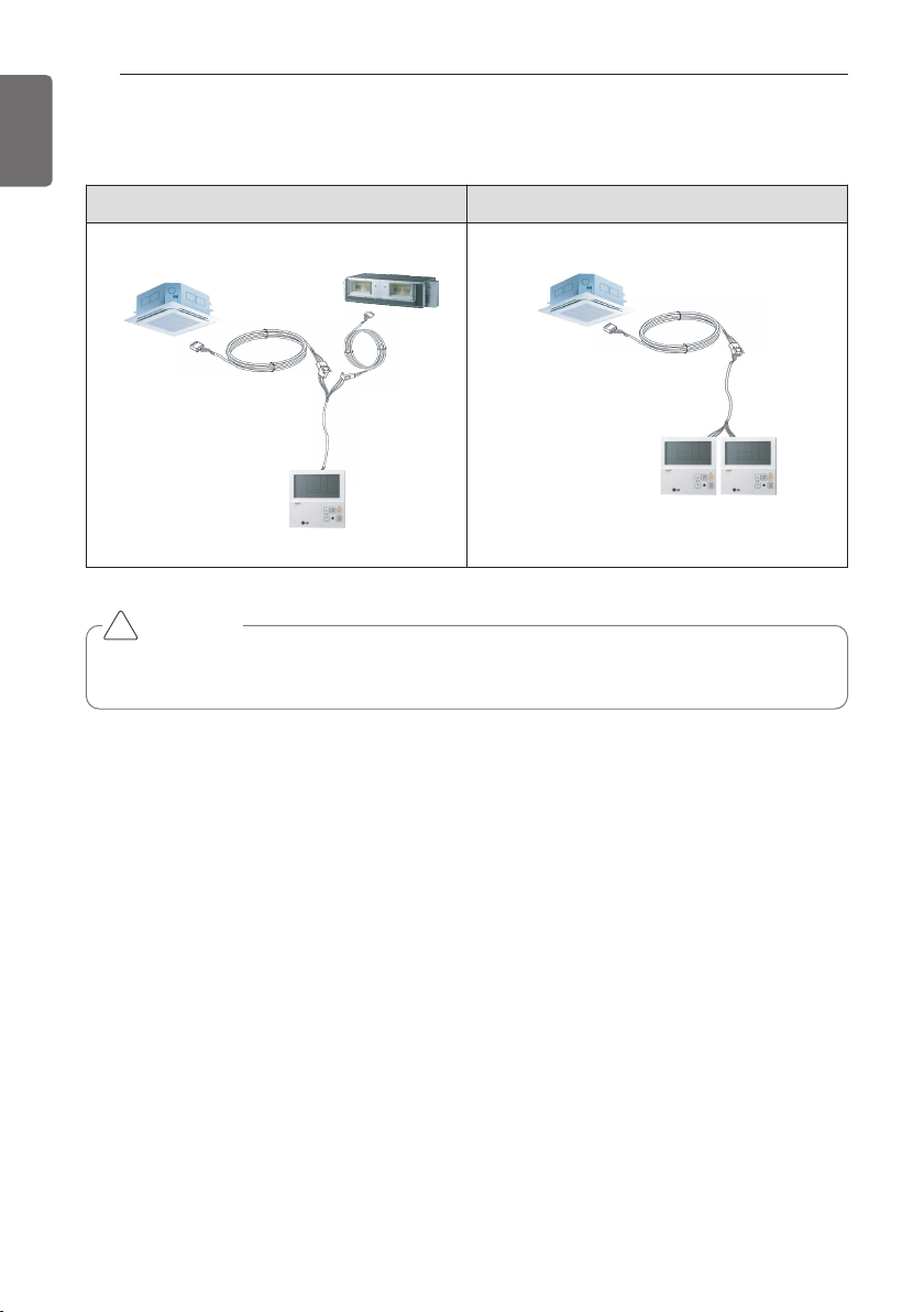
Group Control 2
■ Wired remote controllers + Standard Indoor Units
* It is possible to connect indoor units since Feb. 2009.
* It can be the cause of malfuctions when there is no setting of master and slave.
* In case of Group Control, it is possible to use following functions.
- Selection of operation, stop or mode
- Temperature setting and room temperature check
- Current time change
- Control of flow rate (High/Middle/Low)
- Reservation settings
- It is not possible at some functions.
* It is possible to control 16 indoor units(Max.) with the master wired remote control.
* Other than those, it is same with the Group Control 1.
LGAP Network System
or
Master
Master
Donʼt connect serial 12V line
Display Error Message
SlaveMaster
Slave
Slave
GND
Signal
12 V
20
ENGLISH
THE INDOOR UNIT INSTALLATION
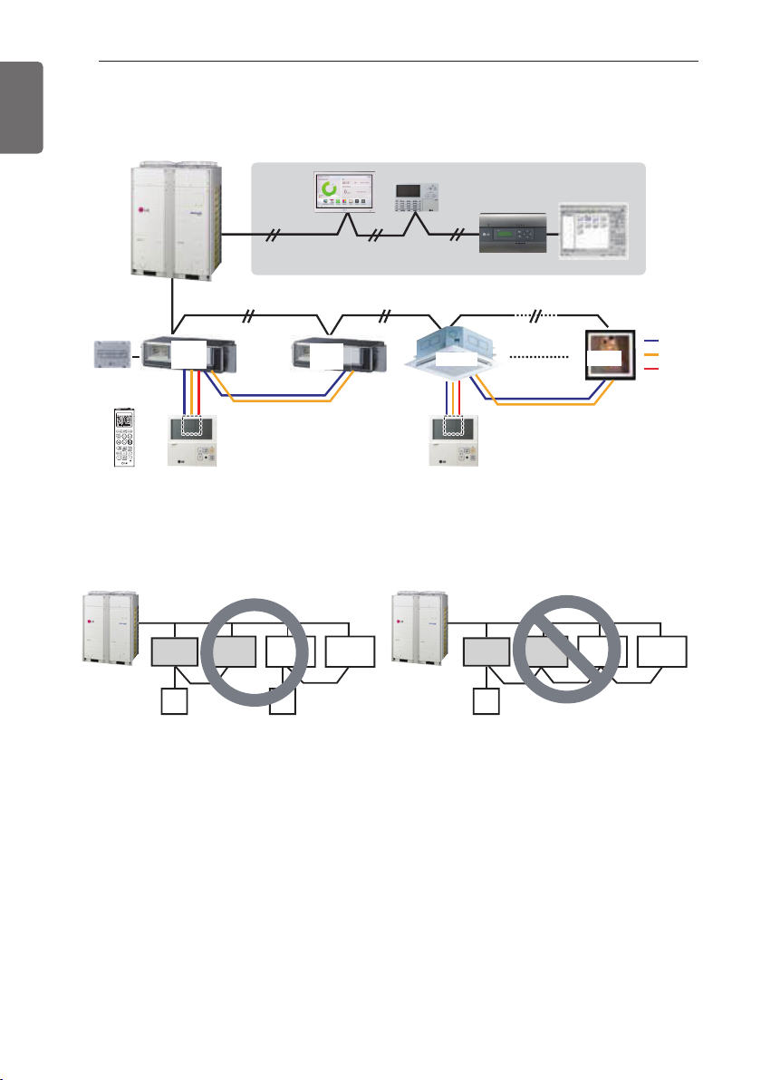
Group Control 3
■ Mixture connection with indoor units and Fresh Air Intake Unit
* In case of connecting with standard indoor unit and Fresh Air Intake Unit, separate Fresh Air In-
take Unit with standard units. (N, M ≤ 16) (Because setting temperature are different.)
* Other than those, it is same with Group Control 1.
LGAP Network System
Slave
Display Error Message
GND
Signal
12 V
M
FAU
Master
Master
FAU
Slave
Display Error Message
or
Master
N
Master
FAU
Standard Standard
FAU FAU
FAU
Standard Standard
* FAU : Fresh Air Intake Unit
Standard: Standard Indoor Unit
21
ENGLISH
THE INDOOR UNIT INSTALLATION
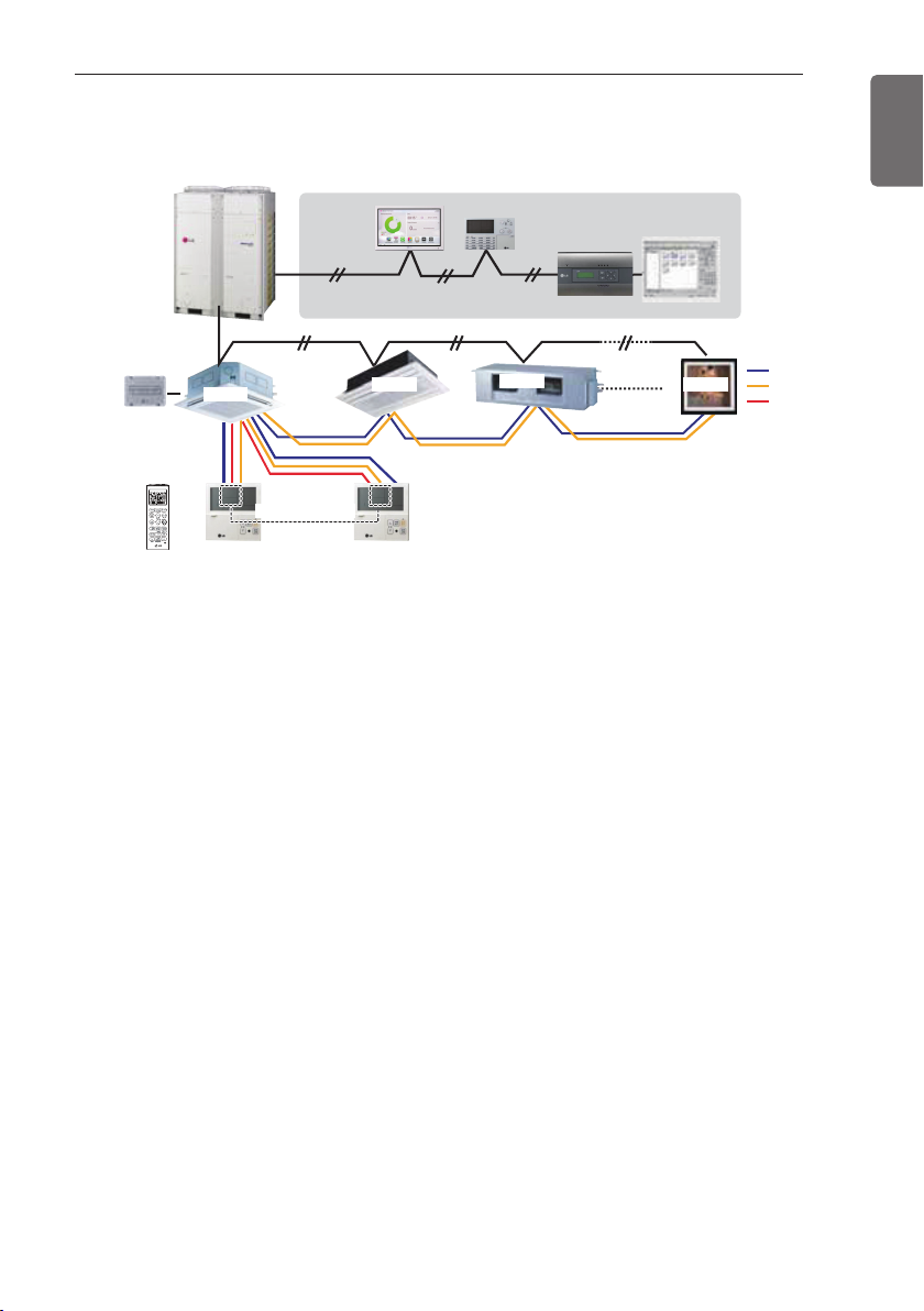
2 Remote Control
■ Wired remote controller 2 + Indoor unit 1
1. It is possible to connect two wired remote controllers (Max.) with one indoor unit.
Set only one indoor unit to Master, set the others to Slave.
Set only one wired remote controller to Master, set the others to Slave.
2. Every types of indoor unit is possible to connect two remote controller.
3. It is possible to use wireless remote controller at the same time.
4. It is possible to connect with Dry Contact and Central controller at the same time.
5. In case that any error occurs at indoor unit, the error code is displayed on the wired remote
controller.
6. There isn't limits of indoor unit function.
LGAP Network System
Slave
GND
Signal
12 V
Master
Master
Display Error Message
Slave
Slave
or
Slave
22
THE INDOOR UNIT INSTALLATION
ENGLISH
Accessories for group control setting
It is possible to set group control by using below accessories.
Indoor unit 2 EA +Wired remote controller Indoor unit 1 EA +Wired remote controller 2EA
* PZCWRCG3 cable used for connection * PZCWRC2 cable used for connection
CAUTION
Apply totally enclosed noncombustible conduit in case of local building code Requiring plenum
cable usage.
!
PZCWRCG3
Master
Slave
PZCWRC2
Master Slave
Master

THE INDOOR UNIT INSTALLATION
23
ENGLISH
Model Designation
Airborne Noise Emission
The A-weighted sound pressure emitted by this product is below 70 dB.
** The noise level can vary depending on the site.
The figures quoted are emission level and are not necessarily safe working levels. Whilst there is
a correlation between the emission and exposure levels, this cannot be used reliably to determine whether or not further precautions are required. Factor that influence the actual level of exposure of the workforce include the characteristics of the work room and the other sources of
noise, i.e. the number of equipment and other adjacent processes and the length of time for
which an operator exposed to the noise. Also, the permissible exposure level can vary from country to country. This information, however, will enable the user of the equipment to make a better
evaluation of the hazard and risk.
Limiting concentration
Limiting concentration is the limit of Freon gas concentration where immediate measures can be
taken without hurting human body when refrigerant leaks in the air. The limiting concentration
shall be described in the unit of kg/m
3
(Freon gas weight per unit air volume) for facilitating calcu-
lation
■ Calculate refrigerant concentration
Limiting concentration: 0.44 kg/m3(R410A)
Total amount of replenished refrigerant in refrigerant facility (kg)
Capacity of smallest room where indoor unit is installed (m
3
)
Refrigerant concentration =
ARN U G48 AV2 4
Serial Number
Combinations of functions
A:Basic function L: Neo Plasma(Wall Mounted)
C: Plasma(Ceiling Cassette)
G: Low Static K: High Sensible Heat
U: Floor Standing without Case
SE/S8 - R: Mirror V: Silver B:Blue(ART COOL Type Panel Clolr)
SF - E: Red V: Silver G:Gold 1: Kiss (Photo changeable)
Q: Console Z: Fresh Air Intake Unit
Chassis Name
Electrical Ratings
1 : 1 Ø, 115 V, 60 Hz
6 : 1 Ø, 220 - 240 V, 50 Hz
3 : 1 Ø, 208/230 V, 60 Hz
Total Cooling Capacity in Btu/h
EX) 48,000 Btu/h ➝ '48' 36,000 Btu/h ➝ '36'
Combination of Inverter Type and Cooling Only or Heat Pump
N: AC Inverter and H/P V: AC Inverter and C/O
U: DC Inverter and H/P and C/O
System with Indoor Unit using R410A
2 : 1 Ø, 220 V, 60 Hz
7 : 1 Ø, 100 V, 50/60 Hz
G :
1 Ø, 220 - 240 V, 50 Hz/1 Ø, 220 V, 60 Hz

24
ENGLISH

MANUAL DE INSTALACIÓN
AIRE
ACONDICIONADO
ESPAÑOL
Por favor, lea completamente este manual antes de instalar el producto.
El trabajo de instalación debe realizarse conforme a los estándares de cableado
nacionales por el personal autorizado.
Una vez haya leído el manual atentamente, guárdelo para futuras referencias.
Aire acondicionado suspendido del techo
Traducción de las instrucciones originales
Modelos:
ARNU18GV1A4 ARNU24GV1A4 ARNU36GV2A4 ARNU48GV2A4
www.lg.com


ESPAÑOL
24

MANUAL DE INSTALAÇÃO
AR
CONDICIONADO
Por favor leia este manual de instalação na íntegra antes de instalar o produto.
O trabalho de instalação deverá ser executado em conformidade com as normas
de cablagem nacionais e apenas por pessoal autorizado.
Por favor guarde este manual de instalação para consultas futuras, depois de o
ler completamente.
Ar Condicionado Teto
Instruções originais
Modelos:
ARNU18GV1A4 ARNU24GV1A4 ARNU36GV2A4 ARNU48GV2A4
PORTUGUÊS
www.lg.com

2
DICAS PARA ECONOMIZAR ENERGIA
PORTUGUÊS
DICAS PARA ECONOMIZAR ENERGIA
• Não resfrie excessivamente o interior da residência. Além de ser prejudicial para a saúde, o equipamento consome mais energia elétrica.
• Bloqueie a luz solar direta com persianas ou cortinas durante o funcionamento do ar condicionado.
• Mantenha portas e janelas fechadas durante o funcionamento do ar condicionado.
• Ajuste a direção do fluxo de ar vertical para circulação do ar interior.
• Aumente a velocidade do ventilador para resfriar ou aquecer o ar interno mais rápido.
• Abra as janelas regularmente para ventilar as divisões uma vez que a qualidade do ar interior pode
deteriorar-se caso o ar condicionado seja usado durante muitas horas.
• Limpe o filtro de ar a cada 2 semanas. O pó e as impurezas recolhidas no filtro de ar podem bloquear o fluxo de ar ou enfraquecer as funções de arrefecimento / desumidificação.
Para os seus registos
Grampear a nota fiscal nesta página caso seja necessário comprovar provar a data da compra ou
para fins de garantia. Escreva o número do modelo e o número de série aqui:
Número do Modelo :
Número de Série :
Pode encontrá-los numa etiqueta na parte lateral de cada unidade.
Nome do Vendedor :
Data de Aquisição :
Para utilizar o seu ar condicionado de forma mais eficiente e reduzir o consumo de energia, basta
seguir as instruções abaixo:

A instalação DEVE estar em conformidade com as normas de construção locais.

Existe o risco de incêndio e explosão.
Deve ser utilizado um gás inerte (nitrogênio) para verificar vazamentos de canalização,
limpeza ou reparação de tubos, etc.
Se estiver a utilizar gases combustíveis, incluindo oxigênio, pode haver o risco de incêndios
e explosões para o produto.
Utilize uma bomba de vácuo ou gás inerte (nitrogênio) quando efetuar o teste de fugas ou a
purga de ar.Não comprima o ar ou oxigênio e não utilize gases inflamáveis.Caso contrário,
isso pode provocar um incêndio ou uma explosão.
Existe o risco de morte, ferimentos, incêndio e explosão.

ÍNDICE
ÍNDICE
5
2 DICAS PARA ECONOMI-
ZAR ENERGIA
3 INSTRUÇÕES DE SEGU-
RANÇA IMPORTANTES
6 PEÇAS DO PRODUTO
6 FERRAMENTAS DE INST-
ALAÇÃO
7 INSTALAÇÃO
7 Selecione a melhor localização
8 INSTALAÇÃO DA UNIDADE
INTERNA
Abrir cobertura-lateral
9
Montagem do parafuso e bucha de
10
fixação
Tubulação de Escoamento da unidade
12
interna
Tubulação de Escoamento
12
Teste de Escoamento
12
Isolamento térmico
13
13 Trabalho de Alargamento
16 Ligação dos Cabos
17 Configuração do Interruptor DIP
18 Configuração do Controle de Grupo
23 Designação do Modelo
23 Emissão de Ruído em Transporte Aéreo
23 Concentração limite
PORTUGUÊS

PEÇAS DO PRODUTO
6
PEÇAS DO PRODUTO
PORTUGUÊS
Cobertura do lado direito
Filtros de ar
(por trás da grelha
de entrada)
Grelha de entrada de ar
(grelha de entrada)
Persiana
Grelha de saída de ar
FERRAMENTAS DE INSTALAÇÃO
ImagemImagem Nome
Chave de parafusos
Berbequim elétrico
Cobertura do lado esquerdo
Nome
Multímetro
Chave hexagonal
Fita métrica, Estilete
Broca de furar
Chave
Chave de torção
Amperímetro
Detector de vazamentos
de gás
Termômetro, Nível
Conjunto de ferramentas para trabalho de
alargamento

INSTALAÇÃO
Selecione a melhor localização
10mm (13/32)
ou mais
300mm (11 - 13/16)
ou mais
INSTALAÇÃO
2500mm (98 - 3/7)
ou mais
7
PORTUGUÊS
700mm (27 - 9/16) ou mais 700mm (27 - 9/16) ou mais

INSTALAÇÃO DA UNIDADE INTERNA
8
INSTALAÇÃO DA UNIDADE INTERNA
PORTUGUÊS

lado esquerdo
INSTALAÇÃO DA UNIDADE INTERNA
9
Abra a estrutura lateral
Passo 1.
- Remova os dois parafusos da cobertura
lateral.
Passo 2.
Painel lado direito
Painel
Painel traseiro
Painel traseiro
- Retire ligeiramente a cobertura lateral do painel. (Bata na cobertura lateral com a palma
da mão no lado posterior)
Passo 4.
- Remover suporte de papel da capa lateral.
Passo 5.
- Bloqueie o encaixe do buraco na cobertura
do lado esquerdo com lenços de papel.
ALERTA
!
Segure a cobertura lateral com a outra
mão enquanto bate para prevenir a
queda.
PORTUGUÊS
Passo 3.
- Remover o suporte do lado do painel.

INSTALAÇÃO DA UNIDADE INTERNA
10
Montagem do parafuso e bucha
de fixação
- Prepare 4 parafusos de suspensão. (Os parafusos devem ser todos do mesmo tamanho.)
- Meça e marque a posição para os parafusos
de Suspensão e o buraco de canalização.
- Faça um furo no teto e insira as buchas.
- Insira os parafusos de suspensão e as por-
PORTUGUÊS
cas no ganchos de suspensão para prender
os parafusos de suspensão no teto.
- Monte os parafusos de suspensão nos ganchos com firmeza.
- Segure os ganchos nos parafusos de Suspensão (ajuste o nível) utilizando parafusos,
porcas e porcas com mola.
- Ajuste o nível com nivelador na direção
esquerda e na parte posterior ajustando os
parafusos de suspensão.
- Ajuste o nível na direção superior ajustando
os parafusos de suspensão. Depois a unidade estará inclinada para o lado inferior garantir a drenagem.
Código do Chassis
VM1 ARNU**GV1A4 1018 355
VM2 ARNU**GV2A4 1418 355
Parafuso de fixação
Teto
Parafuso
Parafusos de
Parafusos de
suspensão
suspensão
Porca
A
Parafuso de suspensão
(Unidade : mm)
A B
B
Barra roscada
(W3/8 ou M10)
Porca
(W3/8 ou M10)
Espaçadores ou
amortecedores
de borracha
(M10)
Arruelas lisas
M10
(acessório)
Arruelas lisas
M10
(acessório)
Porca
(W3/8 ou M10)
- Os seguintes elementos são opcionais.
Parafuso de sustentação - W 3/8 ou M10
Porca - W 3/8 ou M10
Anilha de pressão - M10
Anilha plana - M10
ALERTA
!
Aperte a porca e o perno para prevenir a
queda da unidade.
• Faça o furo na parede para a tubulação
ligeiramente inclinado para o lado externo, usando uma broca de coroa de
Ø 70.
Lado da Parede
Interior Exterior
O gradiente de
inclinação para
drenagem deve ser
de 1/50 ~ 1/100
Parafusos de
Porca
com mola
Camarão
12mm
suspensão
Max.
parafuso
Porca

Teto
INSTALAÇÃO DA UNIDADE INTERNA
ALERTA
!
Informações de instalação para Inclinação
- A inclinação na instalação da unidade interna é muito importante para garantir a drenagem.
- A espessura mínima de isolamento para a canalização de ligação deve ser de 10 mm.
- Se as placas forem fixadas à linha horizontal, a unidade interna, após a instalação, estará inclinada para o baixo.
Vista frontal
- A unidade deve estar na horizontal ou inclinado em ângulo.
- A inclinação deve ser menor ou igual a 1° ou entre 10 a 20 mm, na direção do escoamento, conforme indicado na fig.
10~20 mm
11
PORTUGUÊS
Vista lateral
- A unidade deve estar inclinada para baixo quando a instalação estiver terminada.
Teto
5~10 mm

Anilha
Á
INSTALAÇÃO DA UNIDADE INTERNA
12
Tubulação de Escoamento da
unidade de interna
- A tubulação de escoamento deve ter uma
inclinação descendente (1/50 a 1/100) : certifique-se de não criar inclinação ascendente a
fim de prevenir o fluxo inverso.
- Durante a ligação da mangueira de escoa-
PORTUGUÊS
mento, tenha o cuidado de não forçar a porta
de escoamento da unidade interna.
- Remova a borracha antes de ligar a tubulação de escoamento.
- Prenda a anilha depois de ligar o escoamento
como apresentado abaixo.
Tubulação de Escoamento
Mangueira de
Mangueira de
drenagem
drenagem
Não aumente
Vazamento
de água
Sugestão de
drenagem com
a mangueira
Vazamento
de água
- Certifique-se de executar o isolamento de
calor no dreno.
Material para isolamento térmico: Espuma
de polietileno com uma espessura superior
a 8 mm.
Vazamento
de água
Vala
gua acumulada
para drenagem
Ondulação
Espaço
inferior
a 50 mm
Teste de Escoamento
Utilize o seguinte procedimento para testar o
funcionamento da bomba de drenagem:
Ar
- O dreno deve estar voltado para baixo a fim
de facilitar o escoamento.
Declive
negativo
- Não faça o seguinte ao dreno.
- Posicione as grelhas do difusor de ar para
cima até nivelar (horizontalmente) com a
mão.
- Derrube um copo de água na evaporadora.
- Certifique-se de que a água flui através do
dreno de condensados da unidade interna
sem nenhum vazamento.

Tubo
Mandril
Apontado
para baixo
INSTALAÇÃO DA UNIDADE INTERNA
13
Isolamento térmico
Utilize material de isolamento de calor para a
tubulação de refrigeração com uma excelente
resistência ao calor (acima de 120 °C).
Precauções em locais com alta umidade :
Este ar condicionado foi testado de acordo
com as "Condições normalizadas KS com
neblina" e confirmou que não existe qualquer
falha. No entanto, se for utilizado durante um
longo período de tempo em atmosfera úmida elevada (temperatura do ponto de orvalho:
mais do que 23 °C), pode ocorrer a queda de
gotas de água. Neste caso, adicione material
de isolamento de calor de acordo com o
seguinte procedimento:
Fita adesiva isolante
térmica
Tubulação de
Unidade
interna
- Utilizar lã de vidro adiabática com espessura
de 10 a 20 mm como isolante térmico.
- Utilizar lã de vidro em todas as unidades Teto
fluido refrigerante
Isolante térmico
Trabalho de Alargamento
A principal causa de vazamentos de gás devese a defeitos no trabalho de alargamento.
Alargue os tubos devidamente com os respetivos
cuidados.
Corte os tubos e o cabo
1.
Utilize o acessório de kit de tubulação ou
tubulação adquirida localmente.
2. Meça a distância entre a unidade de ininterna e externa.
3. Corte os tubos um pouco mais compridos
do que a distância medida.
4. Corte o cabo 1,5m mais comprido do que
o comprimento do tubo.
Tubo de
cobre
90°
Inclinado Desigual Irregular
Remoção das rebarbas
PORTUGUÊS
Ligação dos cabos na unidade interna
- Retire a tampa da caixa de controle para a
ligação elétrica entre a unidade interna e
externa.
- Utilize um grampo para fixar o cabo.
Cobertura da caixa de controle
1. Remova completamente as rebarbas das
intersecções da tubulação.
2. Enquanto estiver a remover as rebarbas
coloque a extremidade do da tubulação
de cobre para baixo, a fim de evitar que
sujeiras caiam tubulação.

INSTALAÇÃO DA UNIDADE INTERNA
14
Colocar uma porca
- Remova as porcas de alargamento forne cidas com a unidade interna e externa,
e coloque-as na tubulação tendo já finaliz ado a remoção das rebarbas.
(Não é possível colocá-las depois de terminar a solda)
PORTUGUÊS
Trabalho de Alargamento
1 Segure bem o tubo de cobre numa barra
com dimensão indicada na tabela abaixo.
2 Realize a solda com a ferramenta de soldar.
Diâmetro Externo
mm Polegada mm
Ø6.35 1/4 1.1~1.3
Ø9.52 3/8 1.5~1.7
Ø12.7 1/2 1.6~1.8
Ø15.88 5/8 1.6~1.8
Ø19.05 3/4 1.9~2.1
Barra
Tubo de cobre
Porca de Alargamento
Tubo de cobre
"A"
Barra
Manípulo do grampo
Marca de seta vermelha
A
Manípulo
Culatra
Cone
Verificação
1 Compare a solda com a imagem.
2 Se alguma seção alargada estiver defeitu-
osa,corte-a e repita o trabalho de solda.
Superfície lisa
Comprimento uniforme
a toda a volta
O interior deve estar
brilhante e sem arranhões
= Alargamento impróprio =
Superfície
Inclinado
danificada
Com
fissuras
Espessura
pouco uniforme
Ligar o tubo de instalação e a
mangueira de escoamento à
unidade interna.
1 Alinhe o centro dos tubos e aperte a porca
o suficiente
Tubulação da unidade
interna
Porca de
Alargamento
2 Aperte a porca de alargamento com uma
chave inglesa
Diâmetro Externo
mm Polegada kgf.m
Ø6.35 1/4 1.8~2.5
Ø9.52 3/8 3.4~4.2
Ø12.7 1/2 5.5~6.5
Ø15.88 5/8 6.3~8.2
Ø19.05 3/4 9.9~12.1
Chave inglesa
Tubulação da unidade interna
Tubos
Torção
Chave de bocas
(fixa)
Porca de Alargamento
Tubo de
conexão

INSTALAÇÃO DA UNIDADE INTERNA
Linha de intersecção
intersecção
15
3 Quando necessário estender a mangueira
de escoamento da unidade interna, monte o tubo de escoamento, conforme se
mostra no desenho
Mangueira de
Escoamento
Mangueira de escoamento
da unidade interna
Fita de vinil (estreita)
Adesivo
Envolva o material de isolamento
ao redor da conexão.
1 Sobreponha o material de isolamento na
conexão dos tubos e o material de isolamento da tubulação da unidade interna.
una-os com fita de vinil para que não haja
nenhum vazamento.
Material de isolamento
2 Coloque a linha de intersecção da tubulação
virada para cima.Enrole a área que abriga
a seção de fixação traseira com fita de vinil.
3 Una a tubulação e a mangueira de escoam-
ento em conjunto, ao usar fita de vinil o suficiente para cobrir onde estes se encaixam
na seção traseira da tubulação.
Envolva com fita de vinil
Tubo
PORTUGUÊS
Fita de vinil (larga)
Tubo de escoamento
Linha de
Tubo de gás
Tubo de líquido
Bom exemplo Mau exemplo
* A linha de intersecção da tubulação tem de estar virada para cima.
Tubo de conexão
Fita de vinil (larga)
Cabo de Conexão
Envolva com fita de vinil
Tubo da unidade
interna
Tubo
Fita de vinil (estreita)

INSTALAÇÃO DA UNIDADE INTERNA
16
Ligação dos Cabos
Assegure-se que a cor e o número de condutores elétricos sejam coincidentes nas duas
extremidades.
Certifique-se que a cor dos cabos da unidade externa e o nº do terminal são os mesmos dos
da unidade externa respetiva.
Bloco terminal da unidade externa
PORTUGUÊS
Entrada de alimentação
no interior
ATENÇÃO
Bloco terminal da unidade externa
Unidade
externa
Unidade
externa
-B -A
Controlador central
O cabo de ligação ligado à unidade externa e à unidade externa.
deve respeitar as especificações seguintes (isolamento de borracha,
tipo H07RN-F aprovado pela HAR ou SAA).
ÁREA DE CRUZAMENTO NORMAL
1,0~1,5mm2
Se o cabo de alimentação estiver danificado, este deve ser substituído
por um cabo especial ou conjunto disponível a partir do fabricante ou do seu agente de assistência.
AVISO
Certifique-se de que os parafusos do terminal estão bem apertados.
ATENÇÃO
O cabo de alimentação ligado à unidade deve ser selecionado em conformidade com as especificações seguintes.
ATENÇÃO
Após confirmação das condições acima especificadas, prepare as ligações da seguinte forma:
Não deixe de ter uma alimentação dedicada e especializada para o ar condicionado.Para o
método de cablagem, guie-se pelo diagrama de circuito colocado dentro da cobertura da caixa
do controle.
Instale um disjuntor entre a fonte de alimentação e a unidade.
Os parafusos que apertam a cablagem na caixa dos acessórios elétricos podem soltar-se com as
vibrações, às quais a unidade está sujeita durante o transporte.Certifique-se de que elas se encontram apertadas firmemente.(Se estiverem soltas podem queimar os cabos.)
Confirme as Especificações da Fonte de Alimentação
Verifique se a capacidade elétrica é suficiente.
Certifique-se de que a tensão de arranque é mantida a mais de 90 por cento da tensão nominal
marcada na placa.
Verifique se a seção do cabo é a indicada de acordo com especificações da fonte de alimentação.
(Tenha em atenção a relação entre o comprimento e a seção do cabo.)
Não instale o disjuntor de vazamentos num local molhado ou úmido.A água ou a umidade podem
provocar um curto-circuito.
Os seguintes problemas podem ser provocados por variações de tensão.
Vibração de um interruptor magnético, danos no ponto de contato, corte de fusível, perturbação
do funcionamento normal do dispositivo de proteção de sobrecarga.
Não foi dada alimentação de arranque suficiente ao compressor.

Configuração do Interruptor DIP
Unidade Interna
Contato
INSTALAÇÃO DA UNIDADE DEINTERNA
17
PORTUGUÊS
Posição Teto
Seleção da posição de
instalação
Parte inferior
Unidade externa
Caso os produtos satisfaçam as condições específicas, a função "Endereçamento Automático"
pode iniciar automaticamente com a velocidade melhorada, ao ligar o interruptor DIP #3 da unidunidade externa e ao reiniciar a alimentação.
* Condições específicas:
- Todos os nomes das unidades internas são ARNU****4
- O número de série de ( ) (unidades internas) deve ser posterior a outubro
2013.
Interruptor DIP 7 segmentos
PCI da unidade internas Interruptor DIP da unidade internas

INSTALAÇÃO DA UNIDADE INTERNA
18
Configuração do Controle de Grupo
Controle de Grupo 1
Controle
PORTUGUÊS
internas
interna
Alguns produtos não possuem interruptor DIP na PCI.É possível configurar as unidades
internas para Principal ou Dependente ao utilizar o controle remoto sem fios em vez do
interruptor DIP.Para os detalhes da configuração, por favor consulte o manual do controle
remoto sem fios.
internas
controle
internas
controle
Contato
interna
5.Caso ocorra algum erro na unidade interna, o código de erro é exibido no controlo remoto
com fios.
É possível controlar as outras unidades internas exceto as unidades com erro.

INSTALAÇÃO DA UNIDADE INTERNA
internas Fev.
No caso de controle de grupo, é possível utilizar as funções seguintes.
Configuração de temperatura e verificação da temperatura ambiente
Mudança real de hora
controle da taxa de fluxo (Alta/Média/Baixa)
Configurações de reserva
Não é possível em algumas funções.
Controle de Grupo 2
19
PORTUGUÊS
É possível controlar 16 unidades internas (Max.) com o controle remoto com fios principal.
Além destas, é mesmo com o controle de grupo 1.

INSTALAÇÃO DA UNIDADE INTERNA
20
Grupo de Controle 3
PORTUGUÊS
internas
contrário
internas
(N, M ≤ 16)
Interna

2 Controle Remoto
INSTALAÇÃO DA UNIDADE INTERNA
21
Controle
1. É possível ligar dois controles remotos com fio (Máx.) a uma unidade interna.
Definir apenas uma unidade interna como Principal, e as outras como Dependente.
Configure apenas um controle remoto com fios para principal e os outros como dependentes.
2. Para todos os tipos de unidades internas é possível ligar dois controles remotos.
3. É possível utilizar o controle remoto sem fios, ao mesmo tempo.
4. É possível conectar ao mesmo tempo com o contacto seco e com o controlo central.
5. Caso ocorra algum erro na unidade interna, o código de erro é exibido no controle remo to com fios.
6. Não há limites às funções da unidade interna.
Interna
PORTUGUÊS

INSTALAÇÃO DA UNIDADE INTERNA
22
Acessórios para a configuração do controle de grupo
Controle
interna interna
PORTUGUÊS
ATENÇÃO
Utilize um condutor não combustível no caso da legislação local de construção requerer a
utilização de um cabo pleno.
controle

INSTALAÇÃO DA UNIDADE INTERNA
Designação do Modelo
ARN U G48 AV2 4
Número de série
Combinações de funções
A:Função básica L: Neo Plasma (Unidade de Parede)
C: Plasma (Cassete de Tecto)
G: Estática reduzida K: Calor de alta sensibilidade
U: Unidade de chão sem caixa
SE/S8 - R: Espelho V: Prateado B:Azul(Cor Painel Tipo ART COOL)
SF - E: Vermelho V: Prateado G:Dourado 1: Beijo (Fotografia alterável)
Q: Console Z: Unidade de Entrada de Ar fresco
Nome do chassis
Potências Elétricas
1 : 1 Ø, 115 V, 60 Hz
6 : 1 Ø, 220 - 240 V, 50 Hz
3 : 1 Ø, 208/230 V, 60 Hz
Capacidade total de arrefecimento em Btu/h
000 Btu/h '48' 36,000 Btu/h '36'
EX) 48
Combinação de tipo inversor e apenas arrefecimento ou bomba de calor
N: Inversor CA e H/P V: Inversor CA e C/O
U: Inversor CC e H/P ou C/O
Sistema com unidade interna utilizando R410A
2 : 1 Ø, 220 V, 60 Hz
7 : 1 Ø, 100 V, 50/60 Hz
G :
1 Ø, 220 - 240 V, 50 Hz/1 Ø, 220 V, 60 Hz
Nível de Ruído
O nível de pressão acústica emitido por este produto situa-se abaixo de 70 dB.
** O nível de ruído pode variar dependendo do local.
Os valores mencionados são níveis de emissão e não são necessariamente níveis de trabalho
seguros.Embora não exista uma correlação entre os níveis de emissão e exposição, não pode
ser utilizado de forma confiável para determinar se são necessárias ou não precauções adicionais.Os fatores que influenciam o actual nível de exposição da equipa incluem as características
da sala de trabalho e as outras fontes de ruído, i.e. o número de equipamentos e outros processos adjacentes e a extensão do tempo durante a qual o funcionário está exposto ao ruído.De igual forma, o nível de exposição permitido pode variar de país para país.Esta informação, no entanto, vai permitir ao utilizador do equipamento fazer uma melhor avaliação do perigo e risco.
23
PORTUGUÊS
Concentração limite
A concentração limite é a concentração máxima de gás Freon com a qual é possível tomar medidas sem prejuízo para a saúde humana quando há vazamento do refrigerante.Para facilidade de
cálculo, a concentração limite deve expressar-se em kg/m (peso de gás Freon por unidade de
volume de ar)
Concentração limite: 0,44kg/m (R410A)
Calcule a concentração do refrigerante
Quantidade total (kg) de refrigerante
Concentração do refrigerante =
na instalação
Capacidade do menor cômodo em que
a unidade interna está instalada (m )
3
3

 Loading...