

Page 1
System
Indoor Unit (2 Series)
INSTALLATION MANUAL
LG
Type: Convertible
IMPORTANT
• Please read this installation manual completely before
installing the product.
• Installation work must be performed in accordance with
the national wiring standards by authorized personnel
only.
• Please retain this installation manual for future reference
after reading it thoroughly.
ENGLISH FRANÇAIS ESPAÑOL
Page 2
2 Multi Type Air Conditioner
IMPORTANT!
CAUTION
: Improper installation, adjustment, alteration, service or maintenance can void the warranty.
The weight of the condensing unit requires caution and proper handling procedures when lifting
or moving to avoid personal injury. Use care to avoid contact with sharp or pointed edges.
Safety Precautions
• Always wear safety eye wear and work gloves when installing equipment.
• Never assume electrical power is disconnected. Check with meter and equipment.
• Keep hands out of fan areas when power is connected to equipment.
• R-410A causes frostbite burns.
• R-410A is toxic when burned.
NOTE TO INSTALLING DEALER: The Owners Instructions and Warranty are to be given to the owner
or prominently displayed near the indoor Furnace/Air Handler Unit.
When wiring:
Electrical shock can cause severe personal injury or death. Only a qualified,
experienced electrician should attempt to wire this system.
• Do not supply power to the unit until all wiring and tubing are completed or reconnected and checked.
• Highly dangerous electrical voltages are used in this system. Carefully refer to the wiring diagram and these
instructions when wiring. Improper connections and inadequate grounding can cause accidental injury or death.
• Ground the unit following local electrical codes.
• Connect all wiring tightly. Loose wiring may cause overheating at connection points and a possible fire hazard.
When transporting:
Be careful when picking up and moving the indoor and outdoor units. Get a partner to help, and
bend your knees when lifting to reduce strain on your back. Sharp edges or thin aluminum fins on
the air conditioner can cut your finger.
When installing...
... in a wall: Make sure the wall is strong enough to hold the unit's weight.
It may be necessary to construct a strong wood or metal frame to provide added support.
... in a room: Properly insulate any tubing run inside a room to prevent "sweating" that can cause
dripping and water damage to wall and floors.
... in moist or uneven locatinons: Use a raised concrete pad or concrete blocks provide a solid,
level foundation for the outdoor unit. This prevents water damage and abnormal vibration.
... in an area with high winds: Securely anchor the outdoor unit down with bolts and a metal
frame. Provide a suitable air baffle.
... in a snowy area(for Heat Pump Model): Install the outdoor unit on a raised platform that is
higher than drifting snow. Provide snow vents.
When connecting refrigerant tubing
• Keep all tubing runs as short as possible.
• Use the flare method for connecting tubing.
• Check carefully for leaks before starting the test run.
When servicing
• Turn the power OFF at the main power box(mains) before opening the unit to check or repair
electrical parts and wiring.
• Keep your fingers and clothing away from any moving parts.
• Clean up the site after you finish, remembering to check that no metal scraps or bits of wiring have
been left inside the unit being serviced.
Special warnings
WARNING
• Installation or repairs made by unqualified persons can result in hazards to you and others.
Installation MUST conform with local building codes or, in the absence of local codes, with the National Electrical
Code NFPA 70/ANSI C1-1993 or current edition and Canadian Electrical Code Part1 CSA C.22.1.
• The information contained in the manual is intended for use by a qualified service technician familiar with safety
procedures and equipped with the proper tools and test instruments.
• Failure to carefully read and follow all instructions in this manual can result in equipment malfunction, property
damage, personal injury and/or death.
Please read this instruction sheet completely before installing the product.
This air conditioning system meets strict safety and operating standards. As the installer or service person,
it is an important part of your job to install or service the system so it operates safely and efficiently.
Page 3

Installation Manual 3
ENGLISH
Convertible type Air Conditioner Installation Manual
TABLE OF CONTENTS
Installation
Requirements
Required Parts Required Tools
Safety Precautions............................4
Introduction ........................................9
Symbols used in this manual..........9
Features ...........................................9
Installation ........................................10
Installation Parts ............................10
Installation Tools ............................10
Installation Map..............................11
Select the best Location ..............12
Preparing Work for Installation .....12
Mounting the installation plate(Wall
Mounting) ......................................13
Mounting the anchor Nut &
Bolt(Ceiling Mounting)...................13
Checking the Drainage .................15
Panel Front Assembly ...................15
Installation of Wired Remote
Controller........................................17
Optional Operation of Wired
Remote Controller .........................19
Dip Switch Setting .........................20
Group Control Setting ...................21
❏ Four type "A" screws & plastic
anchors
❏ Connecting cable
❏ Installation guide map
❏ Pipes: Gas side..............3/8", 1/2"
Liquid side ...................1/4"
❏ Insulation materials
❏ Additional drain pipe
(Outer diameter ..............15.5mm)
❏ Two type "B" screws
❏ Level gauge
❏ Screw driver
❏ Electric drill
❏ Hole core drill
(ø25mm, ø45mm, ø70mm)
❏ Horizontal meter
❏ Flaring tool set
❏ Specified torque wrenches
1.8kg.m, 4.2kg.m, 5.5kg.m,
6.6kg.m
(different depending on model No.)
❏ Spanner ........................Half union
❏ A glass of water
❏ Screw driver
❏ Hexagonal wrench(4mm)
❏ Leak detector
❏ Vacuum pump
❏ Gauge manifold
❏ Owner's manual
❏ Thermometer
❏ Remote control holder
Page 4
4 Multi Type Air Conditioner
Safety Precautions
To prevent injury to the user or other people and property damage, the following instructions must be
followed.
■ Be sure to read before installing the air conditioner.
■ Be sure to observe the cautions specified here as they include important items related to safety.
■ Incorrect operation due to ignoring instruction will cause harm or damage. The seriousness is classified
by the following indications.
■ Meanings of symbols used in this manual are as shown below.
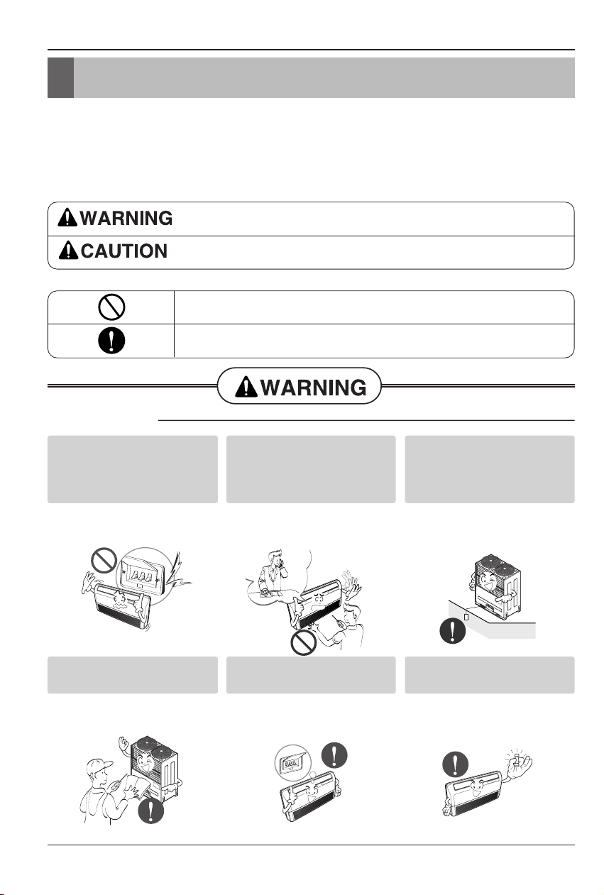
This symbol indicates the possibility of death or serious injury.
This symbol indicates the possibility of injury or damage to properties only.
■ Installation
Be sure not to do.
Be sure to follow the instruction.
Safety Precautions
Do not use a defective or
underrated circuit breaker.
Use this appliance on a
dedicated circuit.
• There is risk of fire or
electric shock.
For electrical work, contact
the dealer, seller, a qualified
electrician, or an Authorized
Service Center.
•
Do not disassemble or repair
the product. There is risk of
fire or electric shock.
Always ground the product.
• There is risk of fire or
electric shock.
Install the panel and the cover
of control box securely.
• There is risk of fire or
electric shock.
Always install a dedicated
circuit and breaker.
• Improper wiring or
installation may cause fire or
electric shock
Use the correctly rated
breaker or fuse.
• There is risk of fire or
electric shock.
Page 5
Installation Manual 5
ENGLISH
Safety Precautions
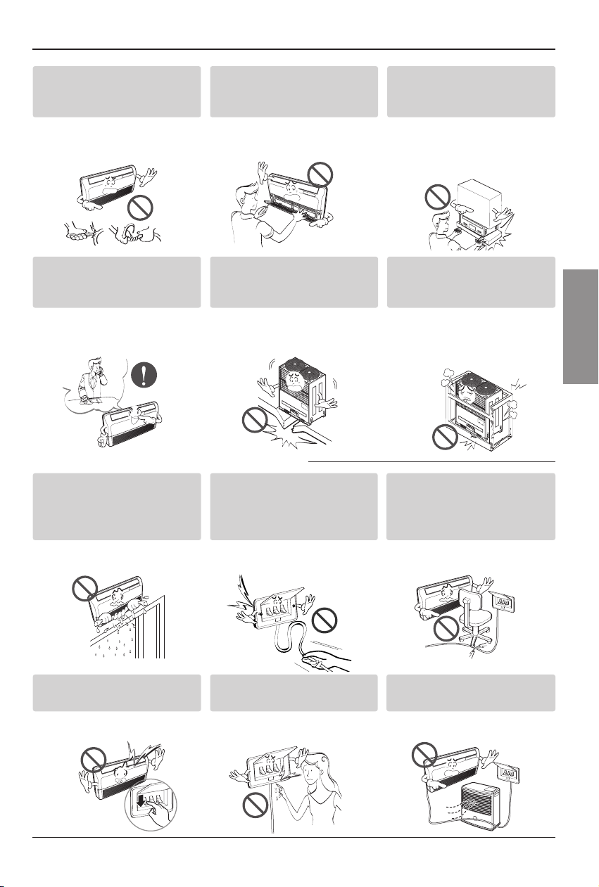
■ Operation
Do not modify or extend the
power cable.
• There is risk of fire or
electric shock.
Do not install, remove, or reinstall the unit by yourself
(customer).
• There is risk of fire, electric
shock, explosion, or injury.
Be cautious when
unpacking and installing
the product.
•
Sharp edges could cause injury.
Be especially careful of the
case edges and the fins on the
condenser and evaporator.
For installation, always
contact the dealer or an
Authorized Service Center.
• There is risk of fire, electric
shock, explosion, or injury.
Do not install the product
on a defective installation
stand.
• It may cause injury,
accident, or damage to the
product.
Be sure the installation area
does not deteriorate with
age.
•
If the base collapses, the air
conditioner could fall with it, causing
property damage, product failure,
and personal injury.
Do not let the air conditioner
run for a long time when the
humidity is very high and a
door or a window is left open.
• Moisture may condense and
wet or damage furniture.
Take care to ensure that
power cable could not be
pulled out or damaged
during operation.
• There is risk of fire or
electric shock.
Do not place anything on
the power cable.
• There is risk of fire or
electric shock.
Do not plug or unplug the power
supply plug during operation.
• There is risk of fire or
electric shock.
Do not touch(operate) the
product with wet hands.
• There is risk of fire or
electrical shock.
Do not place a heater or other
appliances near the power cable.
• There is risk of fire and
electric shock.
Page 6
6 Multi Type Air Conditioner
Safety Precautions
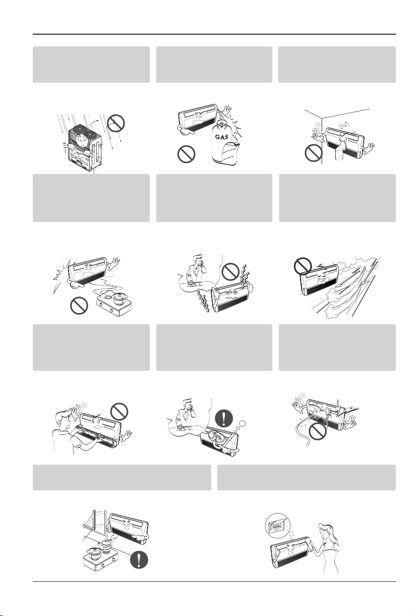
Ventilate the product from time to time when
operating it together with a stove, etc.
• There is risk of fire or electric shock.
Turn the main power off when cleaning or
maintaining the product.
• There is risk of electric shock.
Do not allow water to run
into electric parts.
• It may cause There is risk
of fire, failure of the product,
or electric shock.
Do not store or use flammable
gas or combustibles near the
product.
• There is risk of fire or failure
of product.
Do not use the product in a
tightly closed space for a
long time.
• Oxygen deficiency could
occur.
When flammable gas leaks,
turn off the gas and open a
window for ventilation
before turn the product on.
• Do not use the telephone or
turn switches on or off.
There is risk of explosion or
fire
If strange sounds, or small or
smoke comes from product. Turn
the breaker off or disconnect the
power supply cable.
• There is risk of electric
shock or fire.
Stop operation and close the window
in storm or hurricane. If possible,
remove the product from the window
before the hurricane arrives.
• There is risk of property
damage, failure of product,
or electric shock.
Do not open the inlet grill of the
product during operation. (Do
not touch the electrostatic filter,
if the unit is so equipped.)
• There is risk of physical
injury, electric shock, or
product failure.
When the product is soaked
(flooded or submerged),
contact an Authorized
Service Center.
• There is risk of fire or
electric shock.
Be cautious that water
could not enter the product.
• There is risk of fire, electric
shock, or product damage.
Gasolin
Page 7
Safety Precautions
Installation Manual 7
ENGLISH
■ Operation
■ Installation
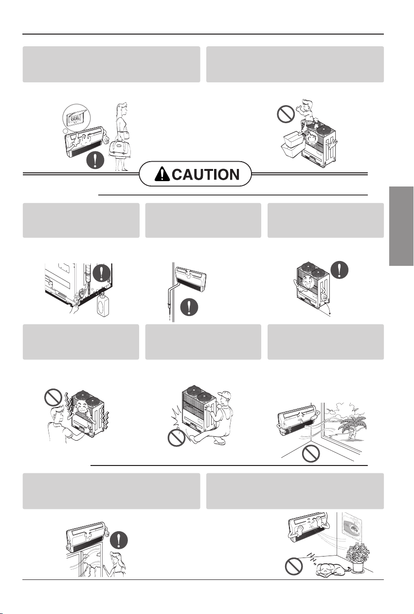
Always check for gas
(refrigerant) leakage after
installation or repair of product.
• Low refrigerant levels may
cause failure of product.
Install the drain hose to
ensure that water is drained
away properly.
• A bad connection may
cause water leakage.
Keep level even when
installing the product.
• To avoid vibration or water
leakage.
Do not install the product where the
noise or hot air from the outdoor unit
could damage the neighborhoods.
• It may cause a problem for
your neighbors.
Use two or more people to
lift and transport the
product.
• Avoid personal injury.
Do not install the product
where it will be exposed to sea
wind (salt spray) directly.
•
It may cause corrosion on the product.
Corrosion, particularly on the condenser
and evaporator fins, could cause product
malfunction or inefficient operation.
When the product is not be used for a long
time, disconnect the power supply plug or
turn off the breaker.
• There is risk of product damage or failure, or
unintended operation.
Take care to ensure that nobody could step
on or fall onto the outdoor unit.
• This could result in personal injury and
product damage.
Do not expose the skin directly to cool air
for long periods of time.
(Don't sit in the draft.)
• This could harm to your health.
Do not use the product for special purposes, such as
preserving foods, works of art, etc. It is a consumer air
conditioner, not a precision refrigeration system.
• There is risk of
damage or loss
of property.
90˚
Page 8
8 Multi Type Air Conditioner
Safety Precautions
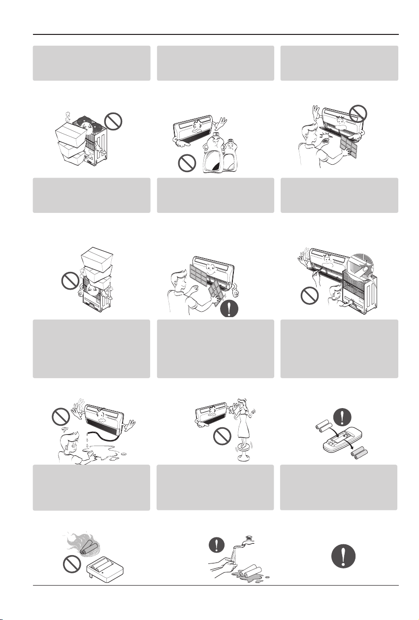
Do not block the inlet or
outlet of air flow.
• It may cause product failure.
Use a soft cloth to clean. Do
not use harsh detergents,
solvents, etc.
• There is risk of fire, electric
shock, or damage to the
plastic parts of the product.
Do not touch the metal parts of
the product when removing the
air filter.They are very sharp!
• There is risk of personal
injury.
Do not step on or put
anyting on the product.
(outdoor units)
• There is risk of personal
injury and failure of product.
Always insert the filter securely.
Clean the filter every two weeks
or more often if necessary.
•
A dirty filter reduces the
efficiency of the air conditioner
and could cause product
malfunction or damage.
Do not insert hands or other objects
through the air inlet or outlet while
the product is operated.
• There are sharp and moving
parts that could cause
personal injury.
Do not drink the water
drained from the product.
• It is not sanitary and could
cause serious health issues.
Use a firm stool or ladder
when cleaning or
maintaining the product.
• Be careful and avoid
personal injury.
Replace the all batteries in the
remote control with new ones
of the same type. Do not mix
old and new batteries or
different types of batteries.
• There is risk of fire or
explosion
Do not recharge or
disassemble the batteries.
Do not dispose of batteries
in a fire.
• They may burn or explode.
If the liquid from the batteries gets
onto your skin or clothes, wash it
well with clean water. Do not use the
remote if the batteries have leaked.
• The chemicals in batteries
could cause burns or other
health
hazards.
If you eat the liquid from the
batteries, brush your teeth and see
doctor. Do not use the remote if
the batteries have leaked.
• The chemicals in batteries could
cause burns or other health
hazards.
Thinner
Wax
Page 9

Installation Manual 9
ENGLISH
Introduction
This symbol alerts you to the risk of electric shock.
This symbol alerts you to hazards that may cause harm to the
air conditioner.
This symbol indicates special notes.
NOTICE
Introduction
Symbols used in this Manual
Features
Air filters
(behind front panel)
Air outlet vent
Vertical louver Horizontal louver
Air inlet vent
Page 10

10 Multi Type Air Conditioner
Installation
Type "A" screw and
plastic anchor(4 EA)
Conduit mounting plate(1 EA)
Installation plate(1 EA) Type "B" screw (2EA)
Installation Parts
Installation
Read carefully, and then follow step by step.
Page 11

Installation Manual 11
ENGLISH
Installation Map
Installation parts you should purchase.
NOTICE
(Left and right
are identical)
(Left and right
are identical)
Sleeve
Bushing-Sleeve
Putty(Gum Type Sealer)
Bend the pipe as closely
on the wall as possible,
but be careful that it
doesn't break.
Vinyl tape (Wide)
• To carry out the drainage
test, remove the air filters
and pour water into the heat
exchanger.
• Apply after carrying out a
drainage test.
Saddle
There should be no space
between ceiling and the unit.
More than
200mm(7-7/8 inch)
More than
200mm(7-7/8 inch)
More than 50mm(2 inch)
More than 50mm(2 inch)
Ceiling Mounting
Wall Mounting
More than
200mm(7-7/8 inch)
Installation
Page 12

12 Multi Type Air Conditioner
Installation
Indoor unit
1. Do not have any heat or steam near the unit.
2. Select a place where there are no obstacles in
front of the unit.
3. Make sure that condensation drainage can be
conveniently routed away.
4. Do not install near a doorway.
5. Ensure that the interval between a wall and the
left (or right) of the unit is more than 200mm(77/8 inch). The unit should be installed as low as
possible on the wall, allowing a minimum of
50mm(2 inch) from floor.
6. Use a stud finder to locate studs to prevent
unnecessary damage to the wall.
Select the best Location
More than
200mm(7-7/8 inch)
More than
50mm(2 inch)
More than
200mm(7-7/8 inch)
More than
200mm(7-7/8 inch)
More than
50mm(2 inch)
More than
200mm(7-7/8 inch)
Preparing Work for Installation
Open panel front
1. Remove the five screws.
2. Release the claws in the 3 places indicated.
3. Pull up the Front Panel.
Cover pipe and cover side remove
1. Pull up the side cover of desired connecting
direction, then cover side is separated.
2. Pick the pipe hole of the side cover.
CAUTION: After removing the
pipe hole, cut the burr for
safety.
When making pipe path through rear
wall, you don’t need to pick the pipe
hole.
Drain hose junction
1. Remove the rubber stopple in the desired
drain direction.
2. Insert drain hose into the handle of drain pan,
and join drain hose and connecting hose
according to the figure by.
NOTICE
2
1
3
Claw
Page 13

Installation Manual 13
ENGLISH
Mounting the installation plate(Wall Mounting)
The wall you select should be strong and solid
enough to prevent vibration
1. Mount the installation plate on the wall with
type "A" screws. If mounting the unit on a
concrete wall, use anchor bolts.
• Mount the installation plate horizontally by
aligning the centerline using a level.
2. Measure the wall and mark the centerline. It
is also important to use caution concerning
the location of the installation plate-routing
of the wiring to power outlets is through the
walls typically. Drilling the hole through the
wall for piping connections must be done
safely.
Installation Plate
Type "A" screw
Installation
Mounting the anchor Nut & Bolt(Ceiling Mounting)
• Prepare 4 suspension bolts. (Each bolts
length should be same.)
• Measure and mark the position for the
Suspension bolts and the piping hole.
• Drill the hole for anchor nut on the ceiling.
• Insert the nuts and washer onto the
suspension bolts for locking the suspension
bolts on the ceiling.
• Mount the suspension bolts to the anchor-
nuts firmly.
• Secure the hangers onto the Suspension
bolts (adjust level roughly.) using nuts,
washers and spring washers.
• Adjust a level with a level gauge on the
direction of left-right, back-forth by adjusting
suspension bolts.
• Adjust a level on the direction of top-bottom
by adjusting supension bolts. Then the unit
will be declined to the bottomside so as to
drain well.
Suspension bolt
piping hole
(Ø45(1-3/4))
235(9-1/4)
50(2)
100(3-5/16)
820(32-1/4)
40(1-9/16)
Washer
Nut
Suspension
bolts
Ceiling
Anchor nut
Reference
of piping
hole (Ø45(1-3/4))
Suspension
bolts
Spring
washer
Max.
12mm
Hangen
Washer
Nut
: Tighten the nut and bolt to prevent unit
falling.
70(2-3/4) 70(2-3/4)
(2-3/4 inch)
Left rear piping
Ø70mm
Installation plate
120(4-3/4)
more than 200mm
(7-7/8 inch)
Hanging bolt
(W3/8 or M10)
Nut
(W3/8 or M10)
Spring washer
(M10)
Ø70mm
(2-3/4 inch)
Right rear piping
Floor
Unit: mm(inch)
Flat washer for M10
(accessory)
Flat washer for M10
(accessory)
Nut
(W3/8 or M10)
Page 14

14 Multi Type Air Conditioner
Installation
: Installation Information For right piping. Follow the instruction below.
Good case
For left piping. Follow the instruction below.
1. Press on the upper side of clamp. (
)
2. Unfold the tubing to downward slowly. (
)
3. Bend the tubing to the left side of chassis.
Bad case
1. Following bending type from right to
left could cause problem of pipe damage.
Page 15

Installation Manual 15
ENGLISH
Checking the Drainage
1. Set the air direction louvers up-and-down to
the position(horizontally) by hand.
To check the drainage.
1. Pour a glass of water on the evaporator using
a kettle.
2. Ensure the water flows through the drain
hose of the indoor unit without any leakage
and goes out the drain exit.
■ Checking the Drainage
1. Remove the Air Filter.
• To remove air filter, take hold of tab and pull
slightly upwards.
2. Check the drainage.
• Spray one or two glasses of water upon the
evaporator.
• Ensure that water flows drain hose of indoor
unit without any leakage.
Drain piping
1. The drain hose should point downward for
easy drain flow.
2. Do not make drain piping like the following.
Installation
Panel Front Assembly
1. Suspend the hook of panel front in
the groove.
2. Press the panel front.
3. Screw up panel front.
1
2
3
Water
leakage
Do not raise
Water
leakage
Accumulated
drain water
Air
Waving
Water
leakage
Tip of drain hose
dipped in water
Ditch
Downward slope
Less than
50mm gap
Page 16

16 Multi Type Air Conditioner
Installation
Connect the wires to the terminals on the control board individually according to the outdoor unit
connection.
• Ensure that the color of the wires of outdoor unit and the terminal No. are the same as those of
indoor unit respectively.
Wiring Connection
Make sure that the screws of the terminal are free from looseness.
Connection method of the connecting cable(Example)
Loose wiring may cause the terminal to overheat or result in unit malfunction.
A fire hazzard may also exist.
Therefore, be sure all wiring is tightly connected.
Terminal Block Indoor
1(L1) 2(L2) 3(A) 4(B)
INDOOR POWER INPUT
Outdoor unit
SODU SODU
Indoor unit
IDU IDU
Central controller
INTERNET
DRY1
DRY2
GND
1(L1) 2(L2)
Power Supply
High Voltage
(208/230V)
3(A)
4(B)
Transmission
Conduit
12V
Lock nut
Main
outdoor unit
Conduit
mounting
plate
Page 17

Installation Manual 17
ENGLISH
Installation
Installation of Wired Remote Controller
1. Connect the wired remote controller
cable to the wired remote controller
installation board as shown in the right
picture.
2. After fixing the cable to the guide slot,
attach the wired remote controller
installation board at the desired location.
• Before fixing the wired remote controller
cable to the guide slot, remove any clogged
part of the case in the direction to install
before the installation.
3. After locating the wired remote
controller installation board at the
desired location, screw the unit firmly.
(When there is a buried box, install the
wired remote controller board to fit the
buried box.)
• Use the screw provided.
4. After fixing the top part of the wired
remote controller to the installation
board as shown in beside picture,
press the bottom part to assemble the
controller to it’s board.
When disassemble the wired remote controller
from the installation board, use the driver as
shown in the right picture and insert it into the
hole with the arrow. And when you pull the
driver in the front direction, the wired remote
controller will be separated.
12V Red wire
SIG Yellow wire
GND Black wire
❊ The wired remote controller cable is connected as factory default.
12V SIG GND
Red
Yellow
Black
Remote Controller
Cable
Guide slot
Fixate the remote
controller cable
to the guide slot.
Use the screws
for fixate the unit
firmly on the wall.
Installation board
<Front side of
installation board>
<Rear side of
installation board>
Top
Bottom
Wall
Side
Wall
Side
Wall
Side
Wall
Side
Wall
Side
Page 18

18 Multi Type Air Conditioner
Installation
5. Use the connecting cable to connect the indoor unit and the wired remote controller.
6. When the distance between the wired remote controller and the indoor unit is 10m
and above, use the extension cable.
When installing the wired remote controller, do not bury it in the wall.
(It can cause damage in the temperature sensor.)
Do not install the cable to be 50m or above.
(It can cause communication error.)
• When installing the extension cable, check the connecting direction of the connector of the remote
controller side and the product side for correct installation.
• If you install the extension cable in the opposite direction, the connector will not be connected.
• Specification of extension cable: 2547 1007 22# 2 core 3 shield 5 or above.
Check whether the connector
is connected correctly.
Connecting cable
Indoor
unit side
Page 19

Installation Manual 19
ENGLISH
Installation
Optional Operation of Wired Remote Controller
Function Code
04:01
Thermistor setting
1. Press button for 4 seconds to
enter the installer setting mode until
timer segment display “01:01”.
2. Repeat pressing button to select Function code
04.
3. Set Thermistor mode by pressing
button
(01: Remote Controller,
02: Indoor, 03: 2TH)
4. Press button to save or release
5. Press button to exit or system
will automatically exit after 25 seconds
without any input.
❈ Therefore system will use value that sensed from indoor unit or remote controller
❈ If you want to know more Optional Operation, please refer to Wide Wired Remote Controller Manual.
Two Thermistor System
Temperature sensor location Function
01 Remote controller Operation in remote controller Temperature sensor
02 Indoor unit Operation in indoor unit temperature sensor
03 2-Thermistor
Operation in lower temperature after comparing the temperature
between the indoor unit and remote controller
Page 20

20 Multi Type Air Conditioner
Installation
Dip Switch Setting
Function Description Setting Off Setting On Default
SW1
SW2
SW3
Communication
Cycle
Group Control
N/A (Default)
N/A (Default)
Selection of Master or Slave
-
-
Master
-
-
Slave
Off
Off
Off
Dry Contact Mode
SW4
Installation
SW5
Heater linkage
SW6
Ventilator linkage
SW7
Vane selection
(Console)
Etc.
SW8
For Multi V Models, Dip switch 1, 2, 6, 8 must be set OFF.
That dip switch is used f
Selection of Dry Contact
Mode
Selection of Manual or Auto
CST – No function
Duct – Fan continuous oper-
ation
CVT – Selection of ceiling or
floor
Console – Concealed or not
N/A
Selection of Ventilator link-
age
Selection of up/down side
Vane
Spare
or other models.
Wired/Wireless remote
controller
operation Mode
-
Continuous operation
Removal
Ceiling
General installation
-
Linkage Removal
Up side + Down side Vane
-
Auto
-
Working
Floor
Concealed
installation
-
Working
Up side Vane
Only
-
Off
Off
Off
Off
Off
Page 21

Installation
Installation Manual 21
ENGLISH
Group Control Setting
1. Group Control 1
■ Wired remote controller 1 + Indoor units
1. It is possible to 16 indoor units(Max) by one wired remote controller.
Set only one indoor unit to Master, set the others to Slave.
2. It is possible to connect with every type of indoor units.
3. It is possible to use wireless remote controller at the same time.
4. It is possible to connect with Dry Contact and Central controller at the same time.
The Master indoor unit is possible to recognize Dry Contact and Central controller only.
5. In case of any error occurs at indoor unit, display on the wired remote controller.
Exception of the error indoor unit, an individual indoor unit control possibility.
6. In case of Group Control, be limited additional functions of indoor unit.
- Selection of operation options (stop/mode/temperature)
- Control of flow rate (strong/middle/weak)
- Time reservation function
- Elevation grille
❈ All kind of indoor units be set possible using a wireless remote controller, except cassette and duct types.
Refer to wireless remote controller manual for setting group control.
❈ It is possible to connect indoor units since Feb. 2009.
In the other cases, please contact LGE.
GND
Signal
12 V
Master
Slave
Slave
Slave
Master
Display Error Message
Only connect serial signal and GND lines
between slave indoor unit
LGAP Network System
Page 22

22 Multi Type Air Conditioner
Installation
2. Group Control 2
■ Wired remote controllers + Indoor units
1. It is possible to control N indoor units by wired remote controller M units. (M+N≤17 Units)
Set only one indoor unit to Master, set the others to Slave.
Set only one wired remote controller to Master, set the others to Slave.
Other than those, it is same with the Group Control 1.
2. It is possible to connect with every type of indoor units.
3. It is possible to use wireless remote controller at the same time.
4. It is possible to connect with Dry Contact and Central controller at the same time.
The Master indoor unit is possible to recognize Dry Contact and Central controller only.
5. In case of any error occurs at indoor unit, display on the wired remote controller.
Exception of the error indoor unit, an individual indoor unit control possibility.
6. In case of Group Control, be limited additional functions of indoor unit.
- Selection of operation options (stop/mode/temperature)
- Control of flow rate (strong/middle/weak)
- Time reservation function
- Elevation grille
❈ All kind of indoor units be set possible using a wireless remote controller, except cassette and duct types.
Refer to wireless remote controller manual for setting group control.
❈ It is possible to connect indoor units since Feb. 2009.
In the other cases, please contact LGE.
GND
Signal
12 V
SlaveSlave
Slave
Slave
Master
Display Error Message
Don’t connect serial 12V line
Master
LGAP Network System
Page 23

Installation
Installation Manual 23
ENGLISH
3. 2 Remote Control
■ Wired remote controller 2 + Indoor unit 1
1. It is possible to connect two wired remote controllers with one indoor unit.
2. Every types of indoor unit is possible to connect two remote controller.
3. It is possible to use wireless remote controller at the same time.
4. It is possible to connect with Dry Contact and Central controller at the same time.
5. In case of any error occurs at indoor unit, display on the wired remote controller.
6. There isn’t limits of indoor unit function.
GND
Signal
12 V
LGAP Network System
Display Error Message
Master
Master
Slave
Page 24

24 Multi Type Air Conditioner
Memo
Page 25

P/No.: MFL42803122
Printed in Korea
After reading this manual, keep it in a place easily accessible to the user for future reference.
 Loading...