


MFL69485426
Rev.00_110718
INSTALLATION MANUAL
AIR
CONDITIONER
Please read this installation manual completely before installing the product.
Installation work must be performed in accordance with the national wiring
standards by authorized personnel only.
Please retain this installation manual for future reference after reading it thoroughly.
WALL MOUNTED
Original instruction
www.lghvac.com
www.lg.com
Copyright © 2018 LG Electronics Inc. All Rights Reserved.
ENGLISH FRANÇAIS ESPAÑOL

2
ENGLISH
IMPORTANT!
Please read this instruction sheet completely before installing the product.
This air conditioning system meets strict safety and operating standards. As the installer or service person, it
is an important part of your job to install or service the system so it operates safely and efficiently.
WARNING
!
• Installation or repairs made by unqualified persons can result in hazards to you and others. Installation of all field wiring and
components MUST conform with local building codes or, in the absence of local codes, with the National Electrical Code 70 and the
National Building Construction and Safety Code or Canadian Electrical code and National Building Code of Canada.
• The information contained in the manual is intended for use by a qualified service technician familiar with safety procedures and
equipped with the proper tools and test instruments.
• Failure to carefully read and follow all instructions in this manual can result in equipment malfunction, property damage, personal
injury and/or death.
CAUTION
Improper installation, adjustment, alteration, service or maintenance can void the warranty. The weight of the condensing unit
requires caution and proper handling procedures when lifting or moving to avoid personal injury. Use care to avoid contact with
sharp or pointed edges.
Safety Precautions
• Always wear safety eye wear and work gloves when installing equipment.
• Never assume electrical power is disconnected. Check with meter and equipment.
• Keep hands out of fan areas when power is connected to equipment.
• R-410A causes frostbite burns.
• R-410A is toxic when burned.
NOTE TO INSTALLING DEALER
: The Owners Instructions and Warranty are to be given to the owner or prominently displayed near the indoor Furnace/Air Handler
Unit.
WARNING
!
When wiring:
Electrical shock can cause severe personal injury or death. Only a qualified, experienced electrician should attempt to wire this
system.
• Do not supply power to the unit until all wiring and tubing are completed or reconnected and checked.
• Highly dangerous electrical voltages are used in this system. Carefully refer to the wiring diagram and these instructions when
wiring. Improper connections and inadequate grounding can cause accidental injury or death.
• Ground the unit following local electrical codes.
• Connect all wiring tightly. Loose wiring may cause overheating at connection points and a possible fire hazard.
• The choice of materials and installations must comply with the applicable local/national or international standards.
When transporting:
Be careful when picking up and moving the indoor and outdoor units. Get a partner to help, and bend your knees when lifting to
reduce strain on your back. Sharp edges or thin aluminum fins on the air conditioner can cut your finger.
When installing...
... in a wall: Make sure the wall is strong enough to hold the unit's weight. It may be necessary to construct a strong wood or metal
... in a room: Properly insulate any tubing run inside a room to prevent "sweating" that can cause dripping and water damage to wall
... in moist or uneven locatinons: Use a raised concrete pad or concrete blocks provide a solid, level foundation for the outdoor unit.
... in an area with high winds: Securely anchor the outdoor unit down with bolts and a metal frame. Provide a suitable air baffle.
... in a snowy area(for Heat Pump Model): Install the outdoor unit on a raised platform that is higher than drifting snow. Provide
When connecting refrigerant tubing
• Keep all tubing runs as short as possible.
• Use the flare method for connecting tubing.
• Check carefully for leaks before starting the test run.
When servicing
• Turn the power OFF at the main power box(mains) before opening the unit to check or repair electrical parts and wiring.
• Keep your fingers and clothing away from any moving parts.
• Clean up the site after you finish, remembering to check that no metal scraps or bits of wiring have been left inside the unit being
frame to provide added support.
and floors.
This prevents water damage and abnormal vibration.
snow vents.
serviced.

TIPS FOR SAVING ENERGY
TIPS FOR SAVING ENERGY
Here are some tips that will help you minimize the power consumption when you use the air
conditioner. You can use your air conditioner more efficiently by referring to the instructions
below:
• Do not cool excessively indoors. This may be harmful for your health and may consume more
electricity.
• Block sunlight with blinds or curtains while you are operating the air conditioner.
• Keep doors or windows closed tightly while you are operating the air conditioner.
• Adjust the direction of the air flow vertically or horizontally to circulate indoor air.
• Speed up the fan to cool or warm indoor air quickly, in a short period of time.
• Open windows regularly for ventilation as the indoor air quality may deteriorate if the air
conditioner is used for many hours.
• Clean the air filter once every 2 weeks. Dust and impurities collected in the air filter may block the
air flow or weaken the cooling / dehumidifying functions.
3
ENGLISH
For your records
Staple your receipt to this page in case you need it to prove the date of purchase or for warranty
purposes. Write the model number and the serial number here:
Model number :
Serial number :
You can find them on a label on the side of each unit.
Dealer’s name :
Date of purchase :

IMPORTANT SAFETY INSTRUCTIONS
4
ENGLISH
IMPORTANT SAFETY INSTRUCTIONS
READ ALL INSTRUCTIONS BEFORE USING THE APPLIANCE.
Always comply with the following precautions to avoid
dangerous situations and ensure peak performance of your
product
WARNING
!
It can result in serious injury or death when the directions are
ignored
CAUTION
!
It can result in minor injury or product damage when the
directions are ignored
WARNING
!
• Installation or repairs made by unqualified persons can result
in hazards to you and others.
• Installation MUST conform with local building codes.
• The information contained in the manual is intended for use
by a qualified service technician familiar with safety
procedures and equipped with the proper tools and test
instruments.
• Failure to carefully read and follow all instructions in this
manual can result in equipment malfunction, property
damage, personal injury and/or death.
Installation
• Don’t use a power cord, a plug or a loose socket which is
damaged.
- Otherwise, it may cause a fire or electrical shock.
• For electrical work, contact the dealer, seller, a qualified
electrician, or an Authorized Service Center.
- Do not disassemble or repair the product. There is risk of fire
or electric shock.

IMPORTANT SAFETY INSTRUCTIONS
• Always ground the product.
- There is risk of fire or electric shock.
• Install the panel and the cover of control box securely.
- There is risk of fire or electric shock.
• Always install a dedicated circuit and breaker.
- Improper wiring or installation may cause fire or electric
shock.
• Use the correctly rated breaker or fuse.
- There is risk of fire or electric shock.
• Do not modify or extend the power cable.
- There is risk of fire or electric shock.
• Do not let the air conditioner run for a long time when the
humidity is very high and a door or a window is left open.
- Moisture may condense and wet or damage furniture.
• Be cautious when unpacking and installing the product.
- Sharp edges could cause injury. Be especially careful of the
case edges and the fins on the condenser and evaporator.
• For installation, always contact the dealer or an Authorized
Service Center.
- There is risk of fire, electric shock, explosion, or injury.
5
ENGLISH
• Do not install the product on a defective installation stand.
- It may cause injury, accident, or damage to the product.
• Be sure the installation area does not deteriorate with age.
- If the base collapses, the air conditioner could fall with it,
causing property damage, product failure, and personal
injury.
• There is a risk of fire and explosion.
- Inert gas (nitrogen) should be used when you check
plumbing leaks, cleaning or repairs of pipes etc.
If you are using combustible gases including oxygen,
product may have the risk of fires and explosions.
• Use a vacuum pump or Inert (nitrogen) gas when doing
leakage test or air purge. Do not compress air or Oxygen and
do not use Flammable gases. Otherwise, it may cause fire or
explosion.
- There is the risk of death, injury, fire or explosion.

6
ENGLISH
Operation
IMPORTANT SAFETY INSTRUCTIONS
• Do not turn on the breaker or power under condition that front
panel, cabinet, top cover, control box cover are removed or
opened.
-
Otherwise, it may cause fire, electric shock, explosion or death.
-
For refrigerant leakage, consult your dealer. When the air
conditioner is to be installed in a small room, it is necessary to
take proper measures so that the amount of any leaked
refrigerant does not exceed the limiting concentration even
when it leaks. If the refrigerant leaks exceeding the level of
limiting concentration, an oxygen deficiency accident may
happen.
• Do not store or use flammable gas or combustibles near the
product.
- There is risk of fire or failure of product.
• Never use flammable spray such as hair spray, lacquer, or
paint near the unit.
• Tear apart and throw away plastic packaging bags so that
children will not play with them.
CAUTION
!
Installation
• Always check for gas (refrigerant) leakage after installation or
repair of product.
- Low refrigerant levels may cause failure of product.
• Install the drain hose to ensure that water is drained away
properly.
- A bad connection may cause water leakage.
• Keep level even when installing the product.
- To avoid vibration or water leakage.
• Use two or more people to lift and transport the product.
- Avoid personal injury.

TABLE OF CONTENTS
3 TIPS FOR SAVING ENERGY
4 IMPORTANT SAFETY INSTRUCTIONS
8 INSTALLATION PARTS
8 INSTALLATION TOOLS
9 INSTALLATION MAP
10 INSTALLATION
10 Select the best Location
10 Fixing Installation Plate
11 Drill a Hole in the Wall
11 Flaring Work
12 Connecting the Piping
16 Checking the Drainage
18 Manual the decor, air filter Assembly & Disassembly
19 Wiring Connection
22 DIP Switch Setting
23 Group Control Setting
28 Model Designation
28 Airborne Noise Emission
28 Limiting concentration
TABLE OF CONTENTS
7
ENGLISH
INSTALLATION PARTS
8
ENGLISH
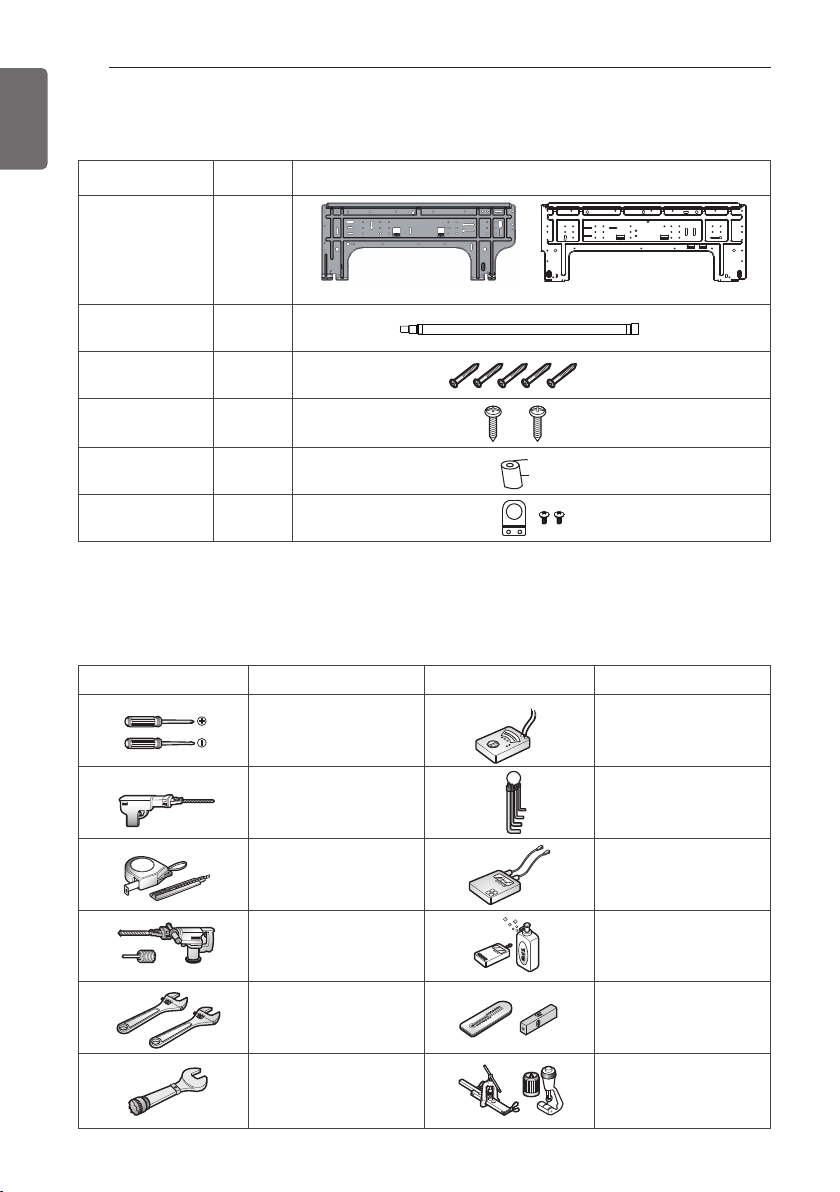
INSTALLATION PARTS
Name
Installation plate
Quantity Shape
1 EA
SJ SK
Drain hose
Type "A" screw
Type "C" screw
Cloth tape
Conduit
mounting plate
Cloth tape is not attached to the product.
1 EA
5 EA
2 EA
1 EA
1 EA
INSTALLATION TOOLS
Figure FigureName
Screw driver
Name
Multi-meter
Electric drill
Measuring tape, Knife
Hole core drill
Spanner
Torque wrench
Hexagonal wrench
Ammeter
Gas-leak detector
Thermometer,
Level
Flaring tool set
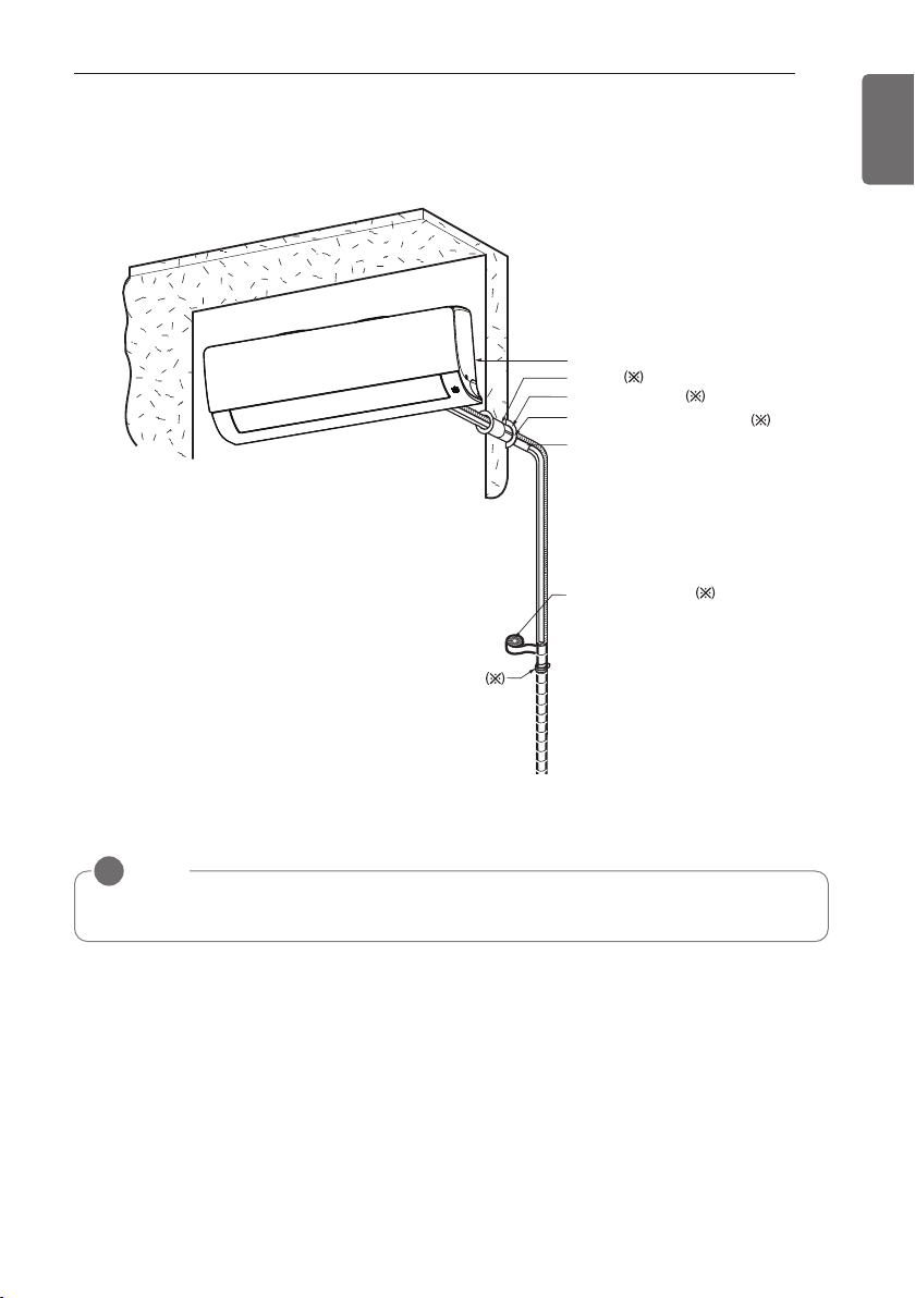
INSTALLATION MAP
Vinyl tape (Wide)
• Apply after carrying out a
drainage test.
• To carry out the drainage
test, remove the air filters
and pour water into the heat
exchanger.
Saddle
Installation plate
Sleeve
Bushing-Sleeve
Putty(Gum Type Sealant)
Bend the pipe as closely
on the wall as possible,
but be careful that it
doesn't break.
INSTALLATION MAP
9
ENGLISH
* The feature can be changed according to type of model.
NOTE
!
• You should purchase the installation parts.

10
83(3-1/4)
Φ6565
(Φ
2-9/16)
Φ6565
(Φ
2-9/16)
83(3-1/4)
ENGLISH
INSTALLATION
INSTALLATION
Select the best Location
- There should not be any heat or steam near
the unit.
- Select a place where there are no obstacles
around of the unit.
- Make sure that condensation drainage can
be conveniently routed away.
- Do not install near a doorway.
- Ensure that the interval between a wall and
the left (or right) of the unit is more than 100
mm. The unit should be installed as high as
possible on the wall, allowing a minimum of
200 mm from ceiling.
- Use a metal detector to locate studs to
prevent unnecessary damage to the wall.
More than
100(4)
More than
2300(90-9/16)
* The feature can be changed according to
type of model.
CAUTION
!
Install the indoor unit on the wall where
the height from the floor is more than
2300 mm.
Fixing Installation Plate
The wall you select should be strong and solid
enough to prevent vibration
1 Mount the installation plate on the wall
with type "A" screws. If mounting the unit
on a concrete wall, use anchor bolts.
- Mount the installation plate horizontally
by aligning the centerline using Horizontal
meter .
More than
200(7-14/16)
Unit : mm(inch)
More than
100(4)
Installation Plate
Type "A" Screws
Chassis
Hook
2 Measure the wall and mark the centerline.
It is also important to use caution
concerning the location of the installation
plate. Routing of the wiring to power
outlets is through the walls typically.
Drilling the hole through the wall for piping
connections must be done safely.
Unit Outline
Φ65
(Φ2-9/16)
Left rear piping
Unit Outline
Φ65
(Φ2-9/16)
Tubatura posteriore sinistra
134(5-1/4)
Place a level on raised tab
418(16-7/16)
Installation Plate
98(3-7/8) 134(5-1/4)
152(6)
Place a level on raised tab
494(19-7/16)
2-9/16)
Measuring
83(3-1/4)
83(3-1/4)
Measuring Tape
Tape
Hanger
418(16-7/16)
Φ65
(Φ2-9/16)
194(7-5/8)
Unit : mm(inch)
504(19-7/8)
Φ65
(Φ2-9/16)
2-9/16)
83(3-1/4)
83(3-1/4)
150(5-7/8)
Unit : mm(inch)
Right rear piping
Right rear piping

Drill a Hole in the Wall
Flare nut
Copper tube
- Drill the piping hole with a Ø 65 mm hole
core drill. Drill the piping hole at either the
right or the left with the hole slightly slanted
to the outdoor side.
WALL
Indoor
Outdoor
5-7mm
(3/16"~5/16")
INSTALLATION
Putting nut on
- Remove flare nuts attached to indoor and
outdoor unit, then put them on pipe/tube
having completed burr removal.
(not possible to put them on after finishing
flare work)
11
ENGLISH
Flaring Work
Main cause for gas leakage is due to defect of
flaring work. Carry out correct flaring work in
the following procedure.
Cut the pipes and the cable
1 Use the piping kit accessory or the pipes
purchased locally.
2 Measure the distance between the indoor
and the outdoor unit.
3 Cut the pipes a little longer than measured
distance.
4 Cut the cable 1.5m longer than the pipe
length.
Copper
pipe
Burrs removal
1. Completely remove all burrs from the cut
cross section of pipe/tube.
2. While removing burrs put the end of the
copper tube/pipe in a downward direction
while removing burrs location is also
changed in order to avoid dropping burrs
into the tubing.
Point down
90 °
Slanted Uneven Rough
Pipe
Reamer
Flaring work
1
Firmly hold copper pipe in a bar with the
dimension shown in below table table below.
2 Carry out flaring work with the flaring tool.
<Wing nut type>
Bar
Pipe diameter
Inch (mm)
Ø 1/4 (Ø 6.35) 1.1~1.3
Ø 3/8 (Ø 9.52) 1.5~1.7
Ø 1/2 (Ø 12.7) 1.6~1.8
Ø 5/8 (Ø 15.88) 1.6~1.8
"A"
Copper pipe
<Clutch type>
A inch (mm)
Wing nut type Clutch type
0~0.02
(0~0.5)

12
ENGLISH
INSTALLATION
Check
1 Compare the flared work with the figure
by.
2 If a flared section is defective, cut it off
and do flaring work again.
Smooth all round
Even length
all round
Inside is shiny without scratches
= Improper flaring =
Surface
damaged
Cracked Uneven
Inclined
thickness
Connecting the Piping
1 Pull the cover at the bottom of the indoor
unit. Pull the cover ① → ②.
2 Remove the cover from the indoor unit.
ڹ
ڸ
ڸ
ڸ
ڹ
3 Pull back the tubing holder.
4 Remove pipe port cover and positioning
the tubing
Indoor unit back side view
Right
Downwards
* The feature can be changed according to
type of model.
Tubing holder
Left
Backwards
Assembly of chassis cover
1 Insert 3 hooks of the chassis cover into
gap of the chassis certainly.
2 Push the hooks to assemble chassis
cover. Push the chassis cover ① → ②.
ڹ
ڸ
ڸ
ڸ
ڸ
ڹ

INSTALLATION
13
ENGLISH
Good case
- Press on the tubing cover and unfold the
tubing to downward slowly. And then bend
to the left side slowly.
Bad case
- Following bending case from right to left
directly may cause damage to the tubing.
* The feature can be changed according to
type of model.
* The feature can be changed according to
type of model.
CAUTION
!
Installation Information. For right piping.
Follow the instruction above.

14
ENGLISH
INSTALLATION
Installation of Indoor Unit
1 Hook the indoor unit onto the upper
portion of the installation plate.( engage
the three hooks at the top of the indoor
unit with the upper edge of the installation
plate) Ensure that the hooks are properly
seated on the installation plate by moving
it left and right
Installation plate
2 Unlock the tubing holder from the chassis
and mount between the chassis and
installation plate in order to separate the
bottom side of the indoor unit from the
wall.
Tubing Holder
* The feature can be changed according to
type of model.
Piping
1 Insert the connecting cable through the
bottom side of indoor unit and connect the
cable (You can see detail contents in
'Connecting the cables' section)
<Left side piping>
<Right side piping>
View
Terminal block of indoor unit
L(L1) N(L2) 3(A) 4(B)
Indoor power input
Slide up the metal
plate cover
Outdoor unit
2 Secure the cable onto the control board
with the cable retainer.
3 Tape the tubing pipe, drain hose and the
connection cable. Be sure that the drain
hose is located at the lowest side of the
bundle. Locating at the upper side can
cause overflow from the drain pan through
the inside of the unit.
<Left side piping>
Tape
Connecting
cable
Drain hose
Connecting pipe
<Right side piping>
View
Terminal block of indoor unit
L(L1) N(L2) 3(A) 4(B)
Indoor power input
Outdoor unit
Slide up the metal
plate cover
Tape
Connecting
cable
Drain hose
Connecting pipe
* The feature can be changed according to
type of model.

INSTALLATION
Gas Pipe
Liquid Pipe
Cutting Line
Cutting Line
Good Case Bad Case
* Tubing cutting line have to be upward.
Vinyl tape(narrow)
Connection pipe
Connecting cable
Vinyl tape (wide)
Wrap with vinyl tape
Indoor unit pipe
Pipe
15
ENGLISH
CAUTION
!
If the drain hose is routed inside the room
insulate the hose with an insulation material*
so that dripping from sweating condensation)
will not damage furniture or floors.
* Foamed polyethylene or equivalent is
recommended.
Connecting the installation pipe
and drain hose to the indoor unit.
1 Align the center of the pipes and
sufficiently tighten the flare nut by hand
Indoor unit tubing Flare nut Pipes
2 Tighten the flare nut with a wrench
Outside diameter
mm inch kgf.m
Ø6.35 1/4 1.8~2.5
Ø9.52 3/8 3.4~4.2
Ø12.7 1/2 5.5~6.5
Ø15.88 5/8 6.3~8.2
Ø19.05 3/4 9.9~12.1
Torque
Wrap the insulation material
around the connecting portion.
1 Overlap the connection pipe insulation
material and the indoor unit pipe insulation
material. Bind them together with vinyl
tape so that there may be no gap.
Insulation material
2 Set the tubing cutting line upward.
Wrap the area which accommodates the
rear piping housing section with vinyl tape.
Torque wrench
Indoor unit tubing
3 When needed to extend the drain hose of
indoor unit, assembly the drain pipe as
shown on the drawing
Drain pipe
Adhesive
Open-end wrench
(fixed)
Flare nut
Connection pipe
Indoor unit drain hose
Vinyl tape(narrow)
3 For left rear piping, bundle the piping and
drain hose together by wrapping them
cloth tape over the range within which
they fit into the rear piping housing
section.
Wrap with cloth tape
Pipe
Cloth tape
Drain hose
* Wrap the piping of the indoor unit that are
visible from the outside with vinyl tape.

16
Downward slope
ENGLISH
INSTALLATION
Finishing the indoor unit
installation
1 Mount the tubing holder in the original
position.
2 Ensure that the hooks are properly seated
on the installation plate by moving it left
and right.
3 Press the lower left and right sides of the
unit against the installation plate until the
hooks engage into their slots (clicking
sound).
4 Finish the assembly by screwing the unit
to the installation plate by using two
pieces of type "C" screws. And assemble a
chassis cover.
Checking the Drainage
To check the drainage
1 Pour a glass of water on the evaporator.
2 Ensure the water flows through the drain
hose of the indoor unit without any
leakage and goes out the drain exit.
Connecting area
drain hose
Leakage
checking
Drain pan
Drain
hose
Leakage
checking
Drain piping
1 The drain hose should point downward for
easy drain flow.
Type 'C' screw

2 Do not make drain piping like the
Do not raise
Water
leakage
Accumulated
drain water
Air
Waving
Water
leakage
Tip of drain hose
dipped in water
Water
leakage
Ditch
Less than
50mm gap
following.
INSTALLATION
17
ENGLISH
* The feature can be changed according to
type of model.

INSTALLATION
18
ENGLISH
Manual the decor, air filter Assembly & Disassembly

INSTALLATION
Wiring Connection
- Connect the wires to the terminals on the control board individually according to the outdoor
unit connection.
- Ensure that the color of the wires of outdoor unit and the terminal No. are the same as those of
indoor unit respectively.
19
ENGLISH
SJ/SK
Terminal block of indoor unit
L(L1) N(L2) 3(A) 4(B)
Indoor power input
※Resistance measurement position for incorrect wiring.
CAUTION
!
The connecting cable connected to the indoor and outdoor unit
should be complied with the following specifications (This
equipment shall be provided with a cable set complying with the
national regulation).
If the supply cable is damaged, it must be replaced by a special
cable or assembly available from the manufacturer of its service
agent.
WARNING
!
Make sure that the screws of the terminal are free from looseness.
Outdoor unit
ODU ODU
Terminal block of outdoor unit
Indoor unit
IDU IDU
Central controller
INTERNET
DRY1
10±3 mm
NORMAL
CROSS-SECTIONAL
AREA 0.75 mm
DRY2
35±5 mm
GN/YL
GND
2
12V
20 mm
CAUTION
!
The Power cord connected to the unit should be selected according to the following
specifications.

INSTALLATION
Round pressure terminal
Power wire (Ground wire)
20
ENGLISH
Precautions when laying power and ground wiring
Use round pressure terminals for connections to the power terminal block.
When laying ground wiring, you must use round pressure terminals.
When none are available, follow the instructions below.
- Do not connect wiring of different thicknesses to the power terminal block. (Slack in the power
wiring may cause abnormal heat.)
- When connecting wiring which is the same thickness, do as shown in the figure below.
Connection method of the connecting cable(Example)
SJ/SK Chassis
L(L1)
N(L2)
3(A) 4(B)
Power Supply
High Voltage
Conduit
Conduit mounting plate
Lock nut
Transmission
INSTALLATION
CAUTION
!
Be sure to test the power line and communication line for incorrect wiring before power is
applied.
1) If the power line and communication line are swapped over, the product will be damaged.
2) Incorrect wiring confirmation test method
: Measure the resistance across the power terminals (L,N) using a multi meter.
- Resistance value of a normal connection: 1MΩ or more
- Incorrect wiring resistance value: 500MΩ or less
CAUTION
!
After the confirmation of the above conditions, prepare the wiring as follows:
1) Never fail to have separate power specially for the air conditioner. As for the method of
wiring, follow the circuit diagram pasted on the inside of control box cover.
2) Provide a circuit breaker switch between power source and the unit.
3) The screw which fasten the wiring in the casing of electrical fittings are liable to come loose
from vibrations to which the unit is subjected during the course of transportation. Check
them and make sure that they are all tightly fastened. (If they are loose, it could give rise to
burn-out of the wires.)
4) Confirm the Specification of power source
5) Confirm that electrical capacity is sufficient.
6) Be sure that the starting voltage is maintained at more than 90 percent of the rated voltage
marked on the name plate.
7) Confirm that the cable thickness is as specified in the power sources specification.
(Particularly note the relation between cable length and thickness.)
8) Do not install the leakage breaker in a place which is wet or moist.
Water or moist may cause short circuit.
9) The following troubles would be caused by voltage drop-down.
- Vibration of a magnetic switch, damage on the contact point there of, fuse breaking,
disturbance to the normal function of a overload protection device.
- Proper starting power is not given to the compressor.
10) Before applying power to the indoor unit, be sure to check for incorrect wiring of the power
and communication lines.
21
ENGLISH

INSTALLATION
22
ENGLISH
DIP Switch Setting
Indoor Unit
Function Description Setting Off Setting On Default
SW1 Communication N/A (Default) - - Off
SW2 Cycle N/A (Default) - - Off
SW3 Group Control
Dry Contact
SW4
Mode
SW5 Installation
SW6 Heater linkage N/A - - Off
Ventilator
linkage
Vane selection
SW7
(Console)
Region selection
SW8 Etc. Spare - - Off
* Whether the DIP Switch function of PCB is applied or not may be different depending on the
model.
Selection of Master
or Slave
Selection of Dry
Contact Mode
Fan continuous
operation
Selection of
Ventilator linkage
Selection of up/down
side Vane
Selection tropical
region
Master Slave Off
Wired/Wireless remote
controller
Selection of Manual or
Auto operation Mode
Continuous operation
Removall
Linkage Removal
Up side + Down side
Vane
General model Tropical model
Working
Up side Vane
Auto
- Off
Only
Off
Off
CAUTION
!
For Multi V Models, DIP switch 1, 2, 6, 8 must be set OFF.
Outdoor Unit
In case that the products meet specific conditions, “Auto addressing” function can start
automatically with the improved speed by turning the DIP switch #3 of the outdoor unit and
resetting the power.
* Specific conditions:
- All names of the indoor units are ARNU****4
- The serial number of Multi V super IV (outdoor units) is after October 2013,
DIP switch 7 segment
Outdoor Unit PCB Outdoor Unit DIP Switch

Group Control Setting
Group Control 1
n Wired remote controller 1 + Standard Indoor Units
or
Master Slave Slave Slave
INSTALLATION
LGAP Network System
23
GND
Signal
12 V
ENGLISH
Display Error Message
Master
Only connect serial signal and
GND lines between indoor units.
n DIP Switch in PCB
① Master Setting
- No. 3 Off
② Slave Setting
- No. 3 On
Indoor Unit DIP Switch
Some products have no DIP switch on PCB. It is possible to set indoor units to Master or Slave
by using the wireless remote controller instead of DIP switch.
For the details of the setting, please refer to the manual of the wireless remote controller.
1. It is possible to 16 indoor units(Max.) by one wired remote controller.
Set only one indoor unit to Master, set the others to Slave.
2. It is possible to connect with every type of indoor units.
3. It is possible to use wireless remote controller at the same time.
4. It is possible to connect with Dry Contact and Central controller at the same time.
- The Master indoor unit is possible to recognize Dry Contact and Central Controller only.
5. In case that any error occurs at indoor unit, the error code is displayed on the wired remote
controller.
It is possible to control the other indoor units except the error units.

INSTALLATION
GND
Signal
12 V
Slave
Slave
Master
or
Donʼt connect serial 12 V line
LGAP Network System
Master
Master Master
Display Error Message
24
ENGLISH
* It is possible to connect indoor units since Feb. 2009.
* It can be the cause of malfuctions when there is no setting of master and slave.
* In case of Group Control, it is possible to use following functions.
- Selection of operation, stop or mode
- Temperature setting and room temperature check
- Current time change
- Control of flow rate (High/Middle/Low)
- Reservation settings
- It is not possible at some functions.
Group Control 2
n Wired remote controllers + Standard Indoor Units
* It is possible to control 16 indoor units(Max.) with the master wired remote control.
* Other than those, it is same with the Group Control 1.

Group Control 3
n Mixture connection with indoor units and Fresh Air Intake Unit
INSTALLATION
25
ENGLISH
LGAP Network System
Slave
Display Error Message
M
FAU
Master
Master
FAU
Slave
Display Error Message
or
Master
N
Master
* In case of connecting with standard indoor unit and Fresh Air Intake Unit, separate Fresh Air
Intake Unit with standard units. (N, M ≤ 16) (Because setting temperature are different.)
* Other than those, it is same with Group Control 1.
FAU
Standard Standard
FAU FAU
FAU
Standard Standard
GND
Signal
12 V
* FAU : Fresh Air Intake Unit
Standard: Standard Indoor Unit

INSTALLATION
26
ENGLISH
2 Remote Control
n Wired remote controller 2 + Indoor unit 1
LGAP Network System
Slave
GND
Signal
12 V
Master
Master
Display Error Message
Slave
Slave
or
Slave
1. It is possible to connect two wired remote controllers (Max.) with one indoor unit.
Set only one indoor unit to Master, set the others to Slave.
Set only one wired remote controller to Master, set the others to Slave.
2. Every types of indoor unit is possible to connect two remote controller.
3. It is possible to use wireless remote controller at the same time.
4. It is possible to connect with Dry Contact and Central controller at the same time.
5. In case that any error occurs at indoor unit, the error code is displayed on the wired remote
controller.
6. There isn't limits of indoor unit function.

INSTALLATION
Accessories for group control setting
It is possible to set group control by using below accessories.
Indoor unit 2 EA +Wired remote controller Indoor unit 1 EA +Wired remote controller 2EA
* PZCWRCG3 cable used for connection * PZCWRC2 cable used for connection
27
ENGLISH
PZCWRCG3
Master
Slave
PZCWRC2
Master Slave
Master
CAUTION
!
Apply totally enclosed noncombustible conduit in case of local building code Requiring plenum
cable usage.

INSTALLATION
28
ENGLISH
Model Designation
ARN U G15 ASJ 4
Serial Number
Combinations of functions
A:Basic function L: Neo Plasma(Wall Mounted)
C: Plasma(Ceiling Cassette) N : Ionizer
G: Low Static K: High Sensible Heat
U: Floor Standing without Case
SE/S8/SJ/SK - R: Mirror V: Silver B:Blue(ART COOL Type Panel Color)
SF - E: Red V: Silver G:Gold 1: Kiss (Photo changeable)
Q: Console Z: Fresh Air Intake Unit
Chassis Name
Electrical Ratings
1 : 1 Ø, 115 V, 60 Hz
6 : 1 Ø, 220 - 240 V, 50 Hz
3 : 1 Ø, 208/230 V, 60 Hz
Total Cooling Capacity in Btu/h
EX) 5,000 Btu/h ➝ '05' 18,000 Btu/h ➝ '18'
Combination of Inverter Type and Cooling Only or Heat Pump
N: AC Inverter and H/P V: AC Inverter and C/O
U: DC Inverter and H/P and C/O
System with Indoor Unit using R410A
❈ LGETA:U Ex) URN
2 : 1 Ø, 220 V, 60 Hz
7 : 1 Ø, 100 V, 50/60 Hz
G :
1 Ø, 220 - 240 V, 50 Hz/1 Ø, 220 V, 60 Hz
Airborne Noise Emission
The A-weighted sound pressure emitted by this product is below 70 dB.
** The noise level can vary depending on the site.
The figures quoted are emission level and are not necessarily safe working levels. Whilst there is
a correlation between the emission and exposure levels, this cannot be used reliably to
determine whether or not further precautions are required. Factor that influence the actual level
of exposure of the workforce include the characteristics of the work room and the other sources
of noise, i.e. the number of equipment and other adjacent processes and the length of time for
which an operator exposed to the noise. Also, the permissible exposure level can vary from
country to country. This information, however, will enable the user of the equipment to make a
better evaluation of the hazard and risk.
Limiting concentration
Limiting concentration is the limit of Freon gas concentration where immediate measures can be
taken without hurting human body when refrigerant leaks in the air. The limiting concentration
shall be described in the unit of kg/m
calculation
Limiting concentration: 0.44 kg/m3 (0.027 lbs/ft3)
n Calculate refrigerant concentration
Refrigerant concentration =
3
(Freon gas weight per unit air volume) for facilitating
Total amount of replenished refrigerant in refrigerant facility [kg(lbs)]
Capacity of smallest room where indoor unit is installed [m
3
(ft3)]

US
CANADA
Please call the installing contractor of your product, as warranty service will be
provided by them.
Service call Number # : (888) LG Canada, (888) 542-2623
Numéro pour les appels de service : LG Canada, 1-888-542-2623
 Loading...