


INSTALLATION MANUAL
AIR
CONDITIONER
ENGLISH FRANÇAIS
ESPAÑOL
Please read this installation manual completely before installing the product.
Installation work must be performed in accordance with the national wiring
standards by authorized personnel only.
Please retain this installation manual for future reference after reading it
thoroughly.
WALL MOUNTED
http://www.lghvac.com
www.lg.com
P/NO : MFL42803117
Copyright © 2012 - 2018 LG Electronics Inc. All Rights Reserved.
IMPORTANT!
Please read this instruction sheet completely before installing the product.
This air conditioning system meets strict safety and operating standards. As the installer or service person,
it is an important part of your job to install or service the system so it operates safely and efficiently.
WARNING
• Installation or repairs made by unqualified persons can result in hazards to you and others.
Installation of all field wiring and components MUST conform with local building codes or, in the absence of local
codes, with the National Electrical Code 70 and the National Building Construction and Safety Code or Canadian
Electrical code and National Building Code of Canada.
• The information contained in the manual is intended for use by a qualified service technician familiar with safety
procedures and equipped with the proper tools and test instruments.
• Failure to carefully read and follow all instructions in this manual can result in equipment malfunction, property
damage, personal injury and/or death.
CAUTION
Safety Precautions
NOTE TO INSTALLING DEALER: The Owners Instructions and Warranty are to be given to the owner
: Improper installation, adjustment, alteration, service or maintenance can void the warranty.
The weight of the condensing unit requires caution and proper handling procedures when lifting
or moving to avoid personal injury. Use care to avoid contact with sharp or pointed edges.
• Always wear safety eye wear and work gloves when installing equipment.
• Never assume electrical power is disconnected. Check with meter and equipment.
• Keep hands out of fan areas when power is connected to equipment.
• R-410A causes frostbite burns.
• R-410A is toxic when burned.
or prominently displayed near the indoor Furnace/Air Handler Unit.
Special warnings
When wiring:
Electrical shock can cause severe personal injury or death. Only a qualified,
experienced electrician should attempt to wire this system.
• Do not supply power to the unit until all wiring and tubing are completed or reconnected and checked.
• Highly dangerous electrical voltages are used in this system. Carefully refer to the wiring diagram and these
instructions when wiring. Improper connections and inadequate grounding can cause accidental injury or death.
• Ground the unit following local electrical codes.
•
Connect all wiring tightly. Loose wiring may cause overheating at connection points and a possible fire hazard.
• The choice of materials and installations must comply with the applicable local/national or international standards.
When transporting:
Be careful when picking up and moving the indoor and outdoor units. Get a partner to help, and
bend your knees when lifting to reduce strain on your back. Sharp edges or thin aluminum fins on
the air conditioner can cut your finger.
When installing...
... in a wall: Make sure the wall is strong enough to hold the unit's weight.
... in a room: Properly insulate any tubing run inside a room to prevent "sweating" that can cause
... in moist or uneven locatinons: Use a raised concrete pad or concrete blocks provide a solid,
... in an area with high winds: Securely anchor the outdoor unit down with bolts and a metal
... in a snowy area(for Heat Pump Model): Install the outdoor unit on a raised platform that is
When connecting refrigerant tubing
• Keep all tubing runs as short as possible.
• Use the flare method for connecting tubing.
• Check carefully for leaks before starting the test run.
When servicing
• Turn the power OFF at the main power box(mains) before opening the unit to check or repair
electrical parts and wiring.
• Keep your fingers and clothing away from any moving parts.
• Clean up the site after you finish, remembering to check that no metal scraps or bits of wiring have
been left inside the unit being serviced.
It may be necessary to construct a strong wood or metal frame to provide added support.
dripping and water damage to wall and floors.
level foundation for the outdoor unit. This prevents water damage and abnormal vibration.
frame. Provide a suitable air baffle.
higher than drifting snow. Provide snow vents.
2 Indoor Unit

Wall Mounted Type Indoor Unit Installation Manual
TABLE OF CONTENTS
ENGLISH
Installation Requirements
Installation Parts.......................4
Safety Precautions ...................5
Installation.................................8
Selection of the best location...8
Fixing Installation Plate............8
Piping Method..........................9
Plumbing materials and storage
methods.................................14
Drain Piping...........................15
Wiring Connection .................16
Required Parts Required Tools
o Installation guide map
o Four type "A" screws & plastic
anchors
o Connecting cable
o Pipes: Gas side
Liquid side
(Refer to Product Data)
o Insulation materials
o Additional drain pipe
o Level gauge
o Screw driver
o Electric drill
o Hole core drill
o Horizontal meter
o Flaring tool set
o Specified torque wrenches
(different depending on model No.)
o Spanner .......Half union
o A glass of water
o Screw driver
o Hexagonal wrench
o Gas-leak detector
o Vacuum pump
o Gauge manifold
Group Control Setting............19
o Two type "B" screws
o Owner's manual
o Thermometer
o Holder Remote Controller
Installation Manual 3
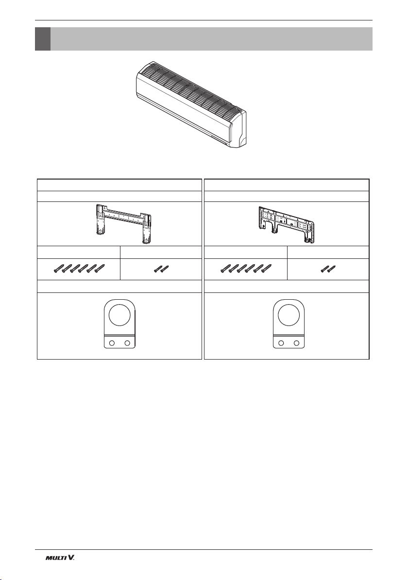
Installation Parts
Installation Parts
SE S5
Installation plate(1EA) Installation plate(1EA)
Type "A" screw (6 EA) Type "B" screw (2 EA)
Conduit mounting plate(1EA) Conduit mounting plate(1EA)
Type "A" screw (6 EA) Type "B" screw (2 EA)
4 Indoor Unit
Safety Precautions
ENGLISH
Safety Precautions
To prevent injury to the user or other people and property damage, the following instructions must be followed.
n Be sure to read before installing the air conditioner.
n Be sure to observe the cautions specified here as they include important items related to safety.
n Incorrect operation due to ignoring instruction will cause harm or damage. The seriousness is classified by the
following indications.
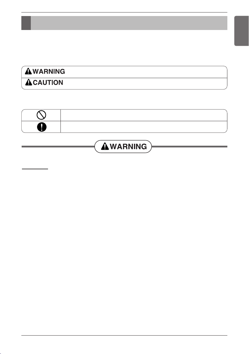
This symbol indicates the possibility of death or serious injury.
This symbol indicates the possibility of injury or damage to properties only.
n Meanings of symbols used in this manual are as shown below.
Be sure not to do.
Be sure to follow the instruction.
Installation
• Do not use a defective or underrated circuit breaker. Use this appliance on a dedicated
circuit.
- There is risk of fire or electric shock.
• For electrical work, contact the dealer, seller, a qualified electrician, or an Authorized
Service Center.
- Do not disassemble or repair the product. There is risk of fire or electric shock.
• Always ground the product.
- There is risk of fire or electric shock.
• Install the panel and the cover of control box securely.
- There is risk of fire or electric shock.
• Always install a dedicated circuit and breaker.
- Improper wiring or installation may cause fire or electric shock
• Use the correctly rated breaker or fuse.
- There is risk of fire or electric shock.
Installation Manual 5
Safety Precautions
• Do not modify or extend the power cable.
- There is risk of fire or electric shock.
• Do not let the air conditioner run for a long time when the humidity is very high and a door
or a window is left open.
- Moisture may condense and wet or damage furniture.
• Be cautious when unpacking and installing the product.
- Sharp edges could cause injury. Be especially careful of the case edges and the fins on
the condenser and evaporator.
• For installation, always contact the dealer or an Authorized Service Center.
- There is risk of fire, electric shock, explosion, or injury.
• Do not install the product on a defective installation stand.
- It may cause injury, accident, or damage to the product.
• Be sure the installation area does not deteriorate with age.
- If the base collapses, the air conditioner could fall with it, causing property damage,
product failure, and personal injury.
• Use a vacuum pump or Inert (nitrogen) gas when doing leakage test or air purge. Do not
compress air or Oxygen and do not use Flammable gases. Otherwise, it may cause fire or
explosion.
- There is the risk of death, injury, fire or explosion.
Operation
• Do not store or use flammable gas or combustibles near the product.
- There is risk of fire or failure of product.
6 Indoor Unit
Safety Precautions
Installation
• Always check for gas (refrigerant) leakage after installation or repair of product.
- Low refrigerant levels may cause failure of product.
• Install the drain hose to ensure that water is drained away properly.
- A bad connection may cause water leakage.
• Keep level even when installing the product.
- To avoid vibration or water leakage.
• Do not install the product where the noise or hot air from the outdoor unit could damage the
neighborhoods.
- It may cause a problem for your neighbors.
• Use two or more people to lift and transport the product.
- Avoid personal injury.
• Do not install the product where it will be exposed to sea wind (salt spray) directly.
- It may cause corrosion on the product. Corrosion, particularly on the condenser and
evaporator fins, could cause product malfunction or inefficient operation.
• If you eat the liquid from the batteries, brush your teeth and see doctor. Do not use the
remote if the batteries have leaked.
- The chemicals in batteries could cause burns or other health
hazards.
ENGLISH
Installation Manual 7

Installation
Installation
Read completely, then follow step by step.
Selection of the best location
• There should not be any heat source or steam
near the unit.
• There should not be any obstacles to prevent the
air circulation.
• A place where air circulation in the room will be
good.
• A place where drainage can be easily obtained.
• A place where noise prevention is taken into con-
sideration.
• Do not install the unit near the door way.
• Ensure the spaces indicated by arrows from the
wall, ceiling, fence, or other obstacles.
The mounting wall should be strong and solid
enough to protect it from the vibration.
Fixing Installation Plate
The wall you select should be strong and solid
enough to prevent vibration
1. Mount the installation plate on the wall with
type "A" screws. If mounting the unit on a concrete wall, use anchor bolts.
• Mount the installation plate horizontally by aligning
the centerline using a level.
Front
Left
Rear left
Right Rear right
More than
100(3-15/16)
Recommended height
2000(78-3/4)
Ɠ
Note: remove obstructions to prevent blockage of airflow path
Chassis
Hook
<SE>
Down right
More than
120(4-23/32)
Installation Plate
Type “A”
More than
100(3-15/16)
Unit: mm (inch)
2. Measure the wall and mark the centerline. It is
also important to use caution concerning the location of the installation plate-routing of the wiring to
power outlets is through the walls typically. Drilling
the hole through the wall for piping connections
must be done safely.
CHASSIS
SE
S5
Distance [mm(inch)]
ABCD
70(2-9/16) 110(4-5/15) 90(3-7/13) 110(4-5/15)
100(3-15/16) 122(4-4/15) 240(9-7/16) 122(4-4/5)
8 Indoor Unit
Chassis
<S5>
(Ø2-9/16 inch)
(Ø2-9/16 inch)
Hook
Ø70mm
Ø70mm
D
C
Left rear piping
133mm
Left rear piping
Installation Plate
Type “A”
Installation plate
<SE>
Installation plate
<S5>
Right rear piping
100mm
Right rear piping
A
B
Ø70mm
(Ø2-9/16 inch)
Ø70mm
(Ø2-9/16 inch)

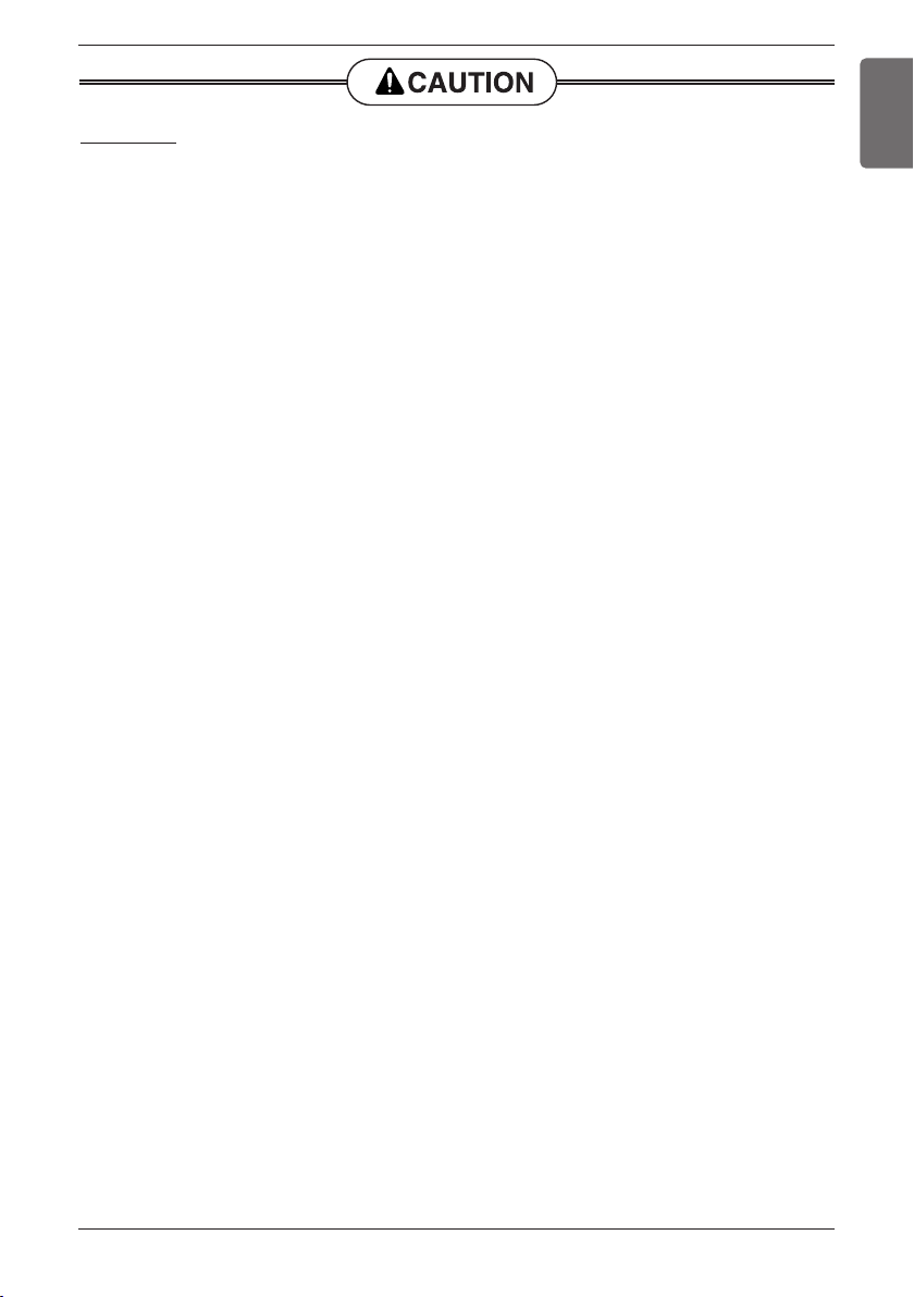
Piping Method
Indoor unit tubing
Flare nut Pipings
n Preparing the indoor unit's piping and drain hose for
installation through the wall.
n Remove the plastic tubing retainer(see illustration
below) and pull the tubing and drain hose away from
chassis.
n Replace the plastic tubing holder in the original position.
Tubing holder
To remove the holder,
press the bottom of
chassis near the holder
upward and pull the tab
out of its hole.
CAUTION : When
install, make sure that
the remaining parts must be
removed clearly so as not to
damage the piping and drain
hose, especially power cord
and connecting cable.
For left rear piping
1. Route the indoor tubing and the drain hose in the
direction of rear left.
1
Press
2
Pull
Installation
3. Tape the tubing, drain hose and the connecting
cable. Be sure that the drain hose is located at the
lowest side of the bundle. Locating at the upper
side can cause drain pan to overflow inside the
unit.
Loop
Connecting
cable
Drain hose
NOTICE
: If the drain hose is routed inside the room,
insulate the hose with an insulation material* so that dripping from "sweating"(condensation) will not damage furniture or floors.
*Foamed polyethylene or equivalent is recommended.
4. Indoor unit installation
n Hook the indoor unit onto the upper portion of the
installation plate.(Engage the two hooks of the rear
top of the indoor unit with the upper edge of the
installation plate.) Ensure that the hooks are properly
seated on the installation plate by moving it left and
right.
Gas side
piping
Liquid side
piping
Connecting
cable
ENGLISH
Drain hose
2. Insert the connecting cable into the indoor unit
from the outdoor unit through the piping hole.
n Do not connect the cable to the indoor unit.
n Make a small loop with the cable for easy connection
later.
n Drill a hole in the wall
• Drill the piping hole with a ø70mm hole core drill.
Drill the piping hole at either the right or the left with
the hole slightly slanted to the outdoor side.
Indoor
WALL
Outdoor
5-7mm
(3/16"~5/16")
Drain hose
Press the lower left and right sides of the unit against
the installation plate until the hooks engage into their
slots(clicking sound).
5. Connecting the pipings to the indoor unit and drain
hose to drain pipe.
n Align the center of the pipings and sufficiently tighten
the flare nut by hand.
Installation Manual 9

Installation
Torque
wrench
Indoor
unit tubing
Spanner (fixed)
Connection
pipe
Flare nut
Vinyl tape(narrow)
Connection
pipe
Connecting cable
Vinyl tape
(wide)
Wrap with vinyl tape
Indoor
unit pipe
Pipe
Wrap with vinyl tape
Drain hose
Pipe
Vinyl tape(wide)
Vinyl tape(narrow)
Adhesive
Drain pipe
Indoor unit
drain hose
Plastic bands
Insulation material
n Tighten the flare nut with a wrench.
n When extending the drain hose at the indoor unit,
install the drain pipe.
6. Wrap the insulation material around the connecting portion.
n Overlap the connection pipe insulation material
and the indoor unit pipe insulation material. Bind
them together with vinyl tape so that there is no
gap.
n Wrap the area which accommodates the rear pip-
ing housing section with vinyl tape.
n Bundle the piping and drain hose together by
wrapping them with vinyl tape over the range within which they fit into the rear piping housing section.
If the split type Indoor unit is installed in a wall having hole or opening near by or back side of the unit,
then the air from other side of the wall can come
inside the condition space through that hole/ opening. That air can cause unwanted dew/ water
droplet formation when it comes in contact with
body of the indoor unit. So all hole or opening on
the wall must be blocked very well to avoid water
dropping from the body of the unit.
Tightening torque
Shutoff
valve size
Ø6.4
Ø9.5
Ø12.7
Ø15.9
Ø22.2
Ø25.4
10 Indoor Unit
5.4-6.6
8.1-9.9
13.5-16.5
27-33 36-44
Shaft(valve body)
Hexagonal
wrench 4mm
Hexagonal
wrench 6mm
Hexagonal
wrench 10mm
Tightening torque N-m(Turn clockwise to close)
Cap(Valve lid) Service port Flare nut
13.5-16.5
18-22
23-27
11.5-13.9
14-17
33-39
50-60
62-75
Gas line piping attached to unit
-
22-28-

Vinyl tape
Adhesive
Drain hose
Indoor unit drain hose
(narrow)
Plastic bands
Insulation material
Vinyl tape
(narrow)
Connection
pipe
Connecting
cable
Indoor
unit piping
Pipe
Vinyl tape
(wide)
Wrap with vinyl tape
Installation plate
Spacer
Indoor unit
800mm(3-5/32 inch)
Indoor unit tubing
Flare nut Pipings
Torque
wrench
Indoor
unit tubing
Spanner (fixed)
Connection
pipe
Flare nut
For right rear piping
Drain pipe
Connecting cable
1. Route the indoor tubing and the drain hose to the
required piping hole position.
2. Insert the piping, drain hose and the connecting
cable into the piping hole.
3. Insert the connecting cable into the indoor unit.
n Don't connect the cable to the indoor unit.
n Make a small loop with the cable for easy connec-
tion later.
4. Tape the drain hose and the connecting cable.
• Connecting cable
Installation
ENGLISH
n When extending the drain hose at the indoor unit,
install the drain pipe.
7. Wrap the insulation material around the connecting portion.
n Overlap the connection pipe heat insulation and
the indoor unit pipe heat insulation material. Bind
them together with vinyl tape so that there is no
gap.
5. Indoor unit installation
n Hang the indoor unit from the hooks at the top of
the installation plate.
n Insert the spacer etc. between the indoor unit and
the installation plate and separate the bottom of
the indoor unit from the wall.
6. Connecting the pipings to the indoor unit and
the drain hose to drain pipe.
n Align the center of the pipings and sufficiently
tighten the flare nut by hand.
n Tighten the flare nut with a wrench.
n Wrap the area which accommodates the rear pip-
ing housing section with vinyl tape.
Installation Manual 11
Installation
Drain hose
Vinyl tape
(narrow)
Pipe
Wrap with
vinyl tape(wide)
Drain hose
Connecting
Piping for
passage through
piping hole
Tubing holder
Hook
Push
2
1
n Bundle the piping and drain hose together by
wrapping them with cloth tape over the range
within which they fit into the rear piping housing
section.
8. Reroute the pipings and the drain hose across
the back of the chassis.
9. Set the pipings and the drain hose to the back of
the chassis with the tubing holder.
n Hook the edge of tubing holder to tap on chassis
and push the bottom of tubing holder to be
engaged at the bottom of chassis.
10. Indoor unit installation
n Remove the spacer.
n Ensure that the hooks are properly seated on the
installation plate by moving it left and right.
Press the lower left and right sides of the unit
against the installation plate until the hooks engage
into their slots(clicking sound).
If the split type Indoor unit is installed in a wall having hole or opening near by or back side of the unit,
then the air from other side of the wall can come
inside the condition space through that hole/ opening. That air can cause unwanted dew/ water
droplet formation when it comes in contact with
body of the indoor unit. So all hole or opening on
the wall must be blocked very well to avoid water
dropping from the body of the unit.
12 Indoor Unit
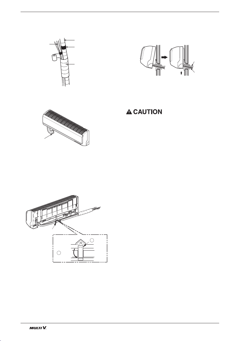
Installation Information. For left piping. Follow the instruction below.
Good case
• Press on the upper side of clamp and unfold the tubing to downward slowly.
※ Make the space between the tubing and the rear panel
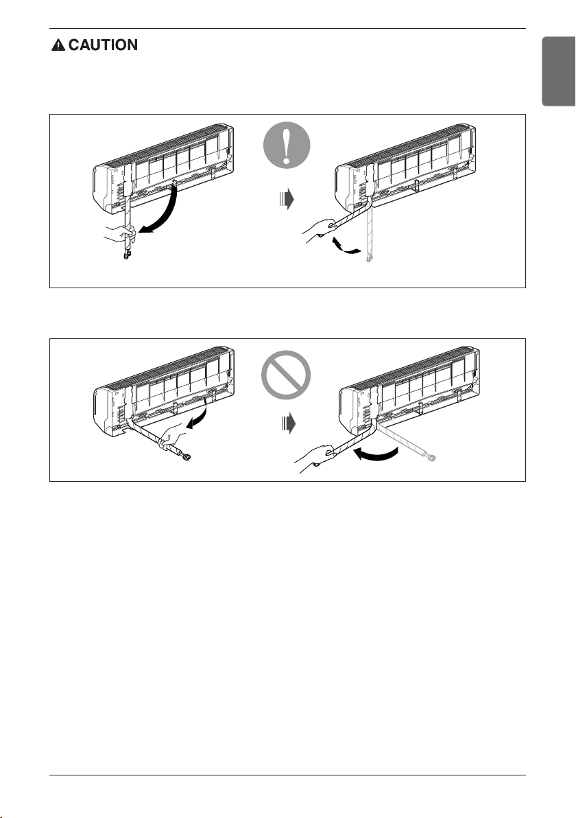
Bad case
• Following bending type from right to left may cause damage to the tubing.
Installation
ENGLISH
Installation Manual 13

Installation
Moisture
Dust
Leakage
Plumbing materials and storage methods
Pipe must be able to obtain the specified thickness and should be used with low
impurities.
Also when handling storage, pipe must be careful to prevent a fracture, deformity
and wound.
Should not be mixed with contaminations such as dust, moisture.
Refrigerant piping on three principles
Drying Cleanliness Airtight
Should be no moisture
inside
Items
No dust inside.
There is no refrigerant
leakage
Cause failure
Countermeas
ure
- Significant hydrolysis of refrigerant oil
- Degradation of refrigerant oil
- Poor insulation of the compressor
- Do not cold and warm
- Clogging of EEV, Capillary
- No moisture in the pipe
- Until the connection is completed, the
plumbing pipe entrance should be
strictly controlled.
- Stop plumbing at rainy day.
- Pipe entrance should be taken side or
bottom.
- When removal burr after cutting pipe,
pipe entrance should be taken down.
- Pipe entrance should be fitted cap
when pass through the walls.
- Degradation of refrigerant oil
- Poor insulation of the compressor
- Do not cold and warm
- Clogging of EEV, Capillary
- No dust in the pipe.
- Until the connection is completed, the
plumbing pipe entrance should be
strictly controlled.
- Pipe entrance should be taken side or
bottom.
- When removal burr after cutting pipe,
pipe entrance should be taken down.
- Pipe entrance should be fitted cap
when pass through the walls.
- Gas shortages
- Degradation of refrigerant oil
- Poor insulation of the compressor
- Do not cold and warm
- Airtightness test should be.
- Brazing operations to comply with standards.
- Flare to comply with standards.
- Flange connections to comply with
standards.
Nitrogen substitution method
Welding, as when heating without nitrogen substitution a large amount of the oxide film is formed on the internal piping.
The oxide film is a caused by clogging EEV, Capillary, oil hole of accumulator and suction hole of oil pump in compressor.
It prevents normal operation of the compressor.
In order to avoid this problem, Welding should be done after replacing air by nitrogen gas.
When welding plumbing pipe, the work is required.
◆How to work
Regulator
Welding Point
Nitrogen gas
Pressure 0.02MPa less
Oxide scale
Note) should not block the outlet side.
When the internal pressure in pipe is above the
atmospheric pressure, pinhole is occurred and it
is a leakage cause.
14 Indoor Unit
Taping
(Should not
contain air)
Auxiliary valve
Nitrogen

Installation
Screw
Pull the right and the left side.
1. Always use the nitrogen.(not use oxygen, carbon dioxide, and a Chevron gas):
Please use the following nitrogen pressure 0.02MPa
Oxygen --------- Promotes oxidative degradation of refrigerant oil.
Because it is flammable, it is strictly prohibited to use
Carbon dioxide --- Degrade the drying characteristics of gas
Chevron Gas ---- Toxic gas occurs when exposed to direct flame.
2. Always use a pressure reducing valve.
3. Please do not use commercially available antioxidant.
The residual material seems to be the oxide scale is observed.
In fact, due to the organic acids generated by oxidation of the alcohol contained in the anti-oxidants, ants nest corrosion
occurs. (causes of organic acid → alcohol + copper + water + temperature)
Drain Piping
1. To remove the front panel from the indoor unit,
remove the front panel from the indoor unit
cabinet.
n Set the air direction louvers up-and-down to the
position(horizontally) by hand.
n Remove the securing screws that retain the front
panel. Pull the lower left and right sides of the
grille toward you and lift it off.
(2.1/7, 2.6/9, 3.5/12 kW/Btu models: 2EA,
3.5/18 kW/Btu models: 3EA)
2. To check the drainage.
n Pour a glass of water on the evaporator.
n Ensure the water flows through the drain hose of
the indoor unit without any leakage and goes out
the drain exit.
ENGLISH
Installation Manual 15

Installation
Connecting cable
Remote control cordRemote control cordRemote control cord
Wiring Connection
1) Connect the wires to the terminals on the
control board individually according to the
outdoor unit connection.
• Ensure that the color of the wires of outdoor
unit and the terminal No. are the same as
those of indoor unit respectively.
Terminal Block Indoor
1(L1) 2(L2) 3(A) 4(B)
INDOOR POWER INPUT
Outdoor unit
SODU SODU
Indoor unit
IDU IDU
Central controller
INTERNET
DRY1
DRY2
2) Attach the Grille onto the cabinet.
• Grasp lower the left and right side of the Grille
and engage four tabs on the top inside edge
of the chassis.
• Press the Grille toward the chassis until it will
be back into place.
Connection method of the connecting cable(Example)
Lock nut
Conduit
Conduit
mounting
plate
GND
Outdoor unit
12V
Power Supply
High Voltage
16 Indoor Unit
1(L1) 2(L2)
(208/230V)
3(A) 4(B)
Transmission
Conduit
Lock nut
Conduit
mounting
plate

Installation
WARNING : Loose wiring may cause the terminal to overheat or result in unit
malfunction.
A fire hazzard may also exist.
Therefore, be sure all wiring is tightly connected.
CAUTION:
After the confirmation of the above conditions, prepare the wiring as follows:
1) Never fail to have an individual power circuit specifically for the air conditioner. As for the
method of wiring, be guided by the circuit diagram posted on the inside of control cover.
2) The screw which fasten the wiring in the casing of electrical fittings are liable to come loose from
vibrations to which the unit is subjected during the course of transportation. Check them and
make sure that they are all tightly fastened. (If they are loose, it could cause burn-out of the
wires.)
3) Specification of power source.
4) Confirm that electrical capacity is sufficient.
5) See to that the starting voltage is maintained at more than 90 percent of the rated voltage marked
on the name plate.
6) Confirm that the cable thickness is as specified in the power source specification.
(Particularly note the relation between cable length and thickness.)
7) In a wet or moist area, always install an earth leakage circuit breaker.
8) The following would be caused by voltage drop.
• Vibration of a magnetic switch, which will damage the contact point, fuse breaking, disturbance of the
normal function of the overload.
9) The means for disconnection from a power supply shall be incorporated in the fixed wiring and
have an air gap contact separation of at least 3mm in each active(phase) conductors.
ENGLISH
Installation Manual 17

Installation
Round pressure terminal
Power wire(Ground wire)
CAUTION :
The connecting cable connected to the indoor and outdoor unit should be complied with the following specifications (This equipment shall be provided with a cord set complying with the
national regulation).
10±3mm
35±5mm
GN/YL
AWG18
20mm
If the supply cord is damaged, it must be replaced by a special cord or assembly available from
the manufacturer of its service agent.
u Precautions when laying power and ground wiring
Use round pressure terminals for connections to the power terminal block.
When laying ground wiring, you must use round pressure terminals.
When none are available, follow the instructions below.
• Do not connect wiring of different thicknesses to the power terminal block. (Slack in the power wiring
may cause abnormal heat.)
• When connecting wiring which is the same thickness, do as shown in the figure below.
• For wiring, use the designated power wire and connect firmly, then secure to prevent outside pressure
being exerted on the terminal block.
• Use an appropriate screwdriver for tightening the terinal screws. A screwdriver with a small head will
strip the head and make proper tighterning impossible.
• Over-tightening the terminal screws may break them.
18 Indoor Unit

Group Control Setting
1. Group Control 1
n Wired remote controller 1 + Indoor units
Installation
ENGLISH
LGAP Network System
Master
Master
Slave
Display Error Message
Slave
Only connect serial signal and GND lines
between slave indoor unit
Slave
GND
Signal
12 V
1. It is possible to 16 indoor units(Max) by one wired remote controller.
Set only one indoor unit to Master, set the others to Slave.
2. It is possible to connect with every type of indoor units.
3. It is possible to use wireless remote controller at the same time.
4. It is possible to connect with Dry Contact and Central controller at the same time.
- The Master indoor unit is possible to recognize Dry Contact and Central Controller only.
- In case of Central controller and Group controller at the same time, it is possible to connect standard 2series indoor units or later since Feb. 2009.
- In case of Central controller setting, the Central controller can control indoor units after setting only
the address of master indoor unit.
- Slave indoor unit will be operated like master indoor unit.
- Slave indoor unit can not be individually controlled by Central controller.
- Some remote controller can’t perform with Dry Contact and Central controller at the same time.
So contact us further information about it.
5. In case of any error occurs at indoor unit, display on the wired remote controller.
Exception of the error indoor unit, an individual indoor unit control possibility.
6. In case of Group Control, it is possible to use following functions.
- Selection of operation options (operation/stop/mode/set temperature)
- Control of flow rate (High/Middle/Low)
- It is not possible at some functions.
h Indoor units be set possible using a wireless remote controller.
This indoor unit be set possible using a wireless remote controller for setting group control.
(type : Wall Mounted, ART COOL Gallery, ART COOL Mirror)
h It is possible to connect indoor units since Feb. 2009. In the other cases, please contact LGE.
h It can be the cause of malfuctions when there is no setting of master and slave.
Installation Manual 19

Installation
2. Group Control 2
Wired remote controllers + Standard Indoor Units
LGAP Network System
Master
Donʼt connect serial 12V line
Display Error Message
Master
Slave
Slave
Slave
Slave
GND
Signal
12 V
It is possible to control N indoor units by wired remote controller M units. (M+N≤17 Units)
Set only one indoor unit to Master, set the others to Slave.
Set only one wired remote controller to Master, set the others to Slave.
Other than those, it is same with the Group Control 1.
20 Indoor Unit

Mixture connection with indoor units and Fresh Air Intake Unit
In case of connecting with standard indoor unit and Fresh Intake Unit, separate Fresh Air Intake
Unit with standard units.
(Because setting temperature are different.)
Other than those, it is same with Group Control 1.
GND
Signal
12 V
LGAP Network System
Display Error Message
FAU
Master
FAU
Slave
Master
Master
Master
Slave
FAU
Standard Standard
FAU FAU
Standard Standard
FAU
* FAU : Fresh Air Intake Unit
Standard: Standard Indoor Unit
3. Group Control 3
Installation
ENGLISH
Installation Manual 21

Installation
Slave
Master
Master
PZCWRCG3
Master Slave
PZCWRC2
1. It is possible to connect two wired remote controllers with one indoor unit.
2. Every types of indoor unit is possible to connect two remote controller.
3. It is possible to use wireless remote controller at the same time.
4. It is possible to connect with Dry Contact and Central controller at the same time.
5. In case of any error occurs at indoor unit, display on the wired remote controller.
6. There isnʼt limits of indoor unit function.
❈ Maximum 2wired remote controllers can be connected with 1 indoor unit.
LGAP Network System
Display Error Message
Master
Master
Slave
Wired remote controller 2 + Indoor unit 1
4. 2 Remote Control
5. Accessories for group control setting
It is possible to set group control by using below accessories.
Indoor unit 2 EA +Wired remote controller Indoor unit 1 EA +Wired remote controller 2EA
h PZCWRCG3 cable used for connection h PZCWRC2 cable used for connection
•
Apply totally enclosed noncombustible conduit in case of local building code Requiring plenum cable usage.
22 Indoor Unit

US
CANADA
Please call the installing contractor of your product, as warranty service will be
provided by them.
Service call Number # : (888) LG Canada, (888) 542-2623
Numéro pour les appels de service : LG Canada, 1-888-542-2623
 Loading...