

Page 1
ENGLISH ITALIANO
ESPAÑOL
FRANÇAIS DEUTSCH
ΕΛΛΗΝΙΚΆ
ČEŠTINA
NEDERLANDS
POLSKI
LIMBA ROMÂNĂ
PORTUGUESE
MAGYAR
БЪЛГАРСKN
SRPSKI
HRVATSKI
SVENDKA
NORSK SUOMI DANSK
EESTI KEEL
MALTI
SLOVENČINA
SLOVENŠČINA
LATVIEŠU VALODA
LIETUVIŲ KALBA
РУССКИЙ ЯЗЫК
УКРАÏНСЬКА
ҚАЗАҚ ТІЛІ
БЕЛАРУСКАЯ МОВА
O‘ZBEK TILI
GAEILGE
МАКЕДОНСКИ
SHQIP
ÍSLENSKA
BOSANSKI
www.lg.com
INSTALLATION MANUAL
ZONE
CONTROLLER
ABZCA
Please read this installation manual completely before installing
the product.
Installation work must be performed in accordance with the
national wiring standards by authorized personnel only.
Please retain this installation manual for future reference after
reading it thoroughly.
P/NO : MFL69265508
Page 2
ZONE CONTROLLER
32
ZONE CONTROLLER
ENGLISH
ZONE CONTROLLER
Accessory
Model Name
ABZCA
Functions
• Dividing area by zones (4zones) and control each zone by its own thermostat and corresponding dampermotor.
• In the cooling mode:
In case of Ceiling Concealed Duct, if the temperature of the zone is
lower than the set temperature in that condition the damper will be
closed & rpm of the fan motor is varied to adjust the reduced requirement of air.
On the other hand:
If the temperature of the zone is higher than the set temperature in
thatc ondition the damper will be open so as to supply cold air to the
zone and vice versa in heating mode.
• In case all the dampers are closed in that condition indoor fan, outdoor
fan & compressor will be off.
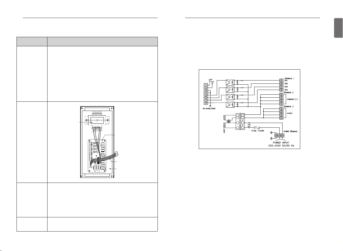
Picture
Parts Supplied
Applicable Models
Applicable to Ceiling Concealed Duct, Ducted Split & Single Package type
air conditioners.
Installation Procedure
- The controller should be mounted to control panel using 4screws supplied.
- Fasten it to any holes on control panel as long as there is enough space to install.
If necessary drill holes to install on prope rposition.
- When drilling, ensure that metal swarf does not foul any electronic components.
Wiring Diagram
- Connect Damper Motor to Zone Controller according to Damper Motor maker's manuals.
- Connect thermostat to Zone Controller according to thermostat maker's manuals.
- Connect main lead wires between main PCB and Zone Controller.
1. Zone
Controller
PCB
2. Trans
3. Case
5. Main lead wires
FactorySupplied:
PCB Controller Zone...........1EA
Trans ..................................1EA
Case ...................................1EA
Cover..................................1EA
Main lead wires..................1EA
Screws ...............................1EA
Supporter ...........................1EA
Purchased Locally:
Damper Motor
Thermostat
Damper
Page 3

5
ENGLISH
4
ZONE CONTROLLER
h If the supply cord is damaged, it must be replaced by the manufacturer, its service agent or
similarly qualified persons in order to avoid a hazard.
h Means for disconnection must be incorporated in the fixed wiring in accordance with the
wiring rules.
h Qualified service technician is only possible to access to product.
Minimum cross-sectional area of conductors
Rated current of appliance
A
Nominal cross-sectional area
mm
2
≤0,2
>0,2 and ≤3
>3 and ≤6
>6 and ≤10
>10 and ≤16
>16 and ≤25
>25 and ≤32
>32 and ≤40
>40 and ≤63
Tinsel cord
a
0,5
a
0,75
1,0 (0,75)
b
1,5 (1,0)
b
2,5
4
6
10
*
a
These cords may only be used if their length does not exceed 2 m between the point
where the cord or cord guard enters the appliance and the entry to the plug.
b
Cords having the cross-sectional areas indicated in the parentheses may be used for
portable appliances if their length does not exceed 2 m.
NOTE: For supply cords supplied with multi-phase appliances, the nominal cross-sectional
area of the conductors is based on the maximum cross-sectional area of the conductors per phase at the supply cord connection to the appliance terminals.
HYUB IL ACTUATOR
12345
6
12345
6
12345
6
Netural(-)
Hot(+)
Action(+)
No Connector
Define(+)
Define(-)
12345
6
Thermostat #1
Thermostat #2
Thermostat #3
Thermostat #4
CH1
CH2
CH3
CH4
Zone
Controller
PCB
Trans
Split Duct Indoor Unit
Trans :12VA
(24V/130mA*4)
COM
COM
COM
COM
214
Heat
W
G
Cool
Power(24V)
Y
R
No Connector
No Connector
CH(1~4)(Cool)
CH(1~4)(Heat)
24V
American Standard Thermostat
No Connector
No Connector
R
C
G
Y1
W1
12345
FAN
HEAT
AC24V(L)
AC24V(N)
COOL
LG THERMOSTAT
AC
24V
24V
24V
24V
PCB
Main
AC220V
50/60Hz
Page 4

Manufacturer: LG Electronics Inc. Changwon 2nd factory, 84, Wanam-ro,
Seongsan-gu, Changwon-si, Gyeongsangnam-do, KOREA
 Loading...