

LG ATNC186ELCA, ATNC246FLAA, AVNC186BLAA, ATNC246FLCA, ABNC246HLAA Service Manual
...
LG
Universal System
Air Conditioner
SERVICE MANUAL
LG
CAUTION
website http://www.lgservice.com
e-mail http://www.lgeservice.com/techsup.html
• BEFORE SERVICING THE UNIT, READ THE SAFETY
PRECAUTIONS IN THIS MANUAL.
• ONLY FOR AUTHORIZED SERVICE PERSONNEL.

2 Universal System Air Conditioner
TABLE OF CONTENTS
Table of contents Page
1. Models List.......................................................................................................................3
2. Model Number Nomenclature..........................................................................................4
3. Safety Precautions...........................................................................................................5
4. Feature & Benefits ...........................................................................................................9
5. List of Functions.............................................................................................................13
6. Function of Remote Control...........................................................................................16
7. Specifications.................................................................................................................21
8. Dimensional Drawings ...................................................................................................33
9. Wiring Diagrams.............................................................................................................43
10. Refrigerant Cycle Diagrams.........................................................................................52
11. Electrical Data..............................................................................................................54
12. Operation Range..........................................................................................................55
13. External Static Pressure & Air flow ..............................................................................56
14. Installation....................................................................................................................60
15. Electronic Control Device.............................................................................................78
16. Schematic Diagram......................................................................................................81
17. Exploded View and Replacement Parts List ................................................................85

Models List
Service Manual 3
Nominal Capacity
Indoor Units Outdoor Units Power Supply
kW Btu/h Type Model Name Model Name Ø,V,Hz
Ceiling Cassette ATNC186ELAA
Ceiling Cassette ATNC186ELCA
5.3 18K
Ceiling Concealed Duct ABNC186HLAA
AUUC186A/AB
Ceiling & Floor AVNC186BLAA
Ceiling Cassette ATNC246FLAA
Ceiling Cassette ATNC246FLCA
7.0 24K
Ceiling Concealed Duct ABNC246HLAA
AUUC246A/AB 1Ø, 220-240V, 50Hz
Ceiling & Floor AVNC246BLAA
Ceiling Cassette ATNC306FLAA
Ceiling Cassette ATNC306FLCA
8.8 30K
Ceiling Concealed Duct ABNC306GLAA
AUUC306A/AB
Ceiling & Floor AVNC306BLAA
Ceiling Cassette ATNC368DLAA
10.6 36K Ceiling Cassette ATNC368DLCA AUUC368A/AB
Ceiling Concealed Duct ABNC368GLAA
Ceiling Cassette ATNC488DLAA
14.1 48K Ceiling Cassette ATNC488DLCA AUUC488A/AB 3Ø, 380-415V, 50Hz
Ceiling Concealed Duct ABNC488ELAA
Ceiling Cassette ATNC608DLAA
17.6 60K Ceiling Cassette ATNC608DLCA AUUC608A/AB
Ceiling Concealed Duct ABNC608ELAA
1.1 Cooling Only
Ceiling Cassette ATNH186ELAA
Ceiling Cassette ATNH186ELCA
5.3 18k
Ceiling Concealed Duct ABNH186HLAA
AUUH186A/AB
Ceiling & Floor AVNH186BLAA
Ceiling Cassette ATNH246FLAA
Ceiling Cassette ATNH246FLCA
7.0 24k
Ceiling Concealed Duct ABNH246HLAA
AUUH246A/AB
1Ø, 220-240V, 50Hz
Ceiling & Floor AVNH246BLAA
Ceiling Cassette ATNH306FLAA
Ceiling Cassette ATNH306FLCA
8.8 30k
Ceiling Concealed Duct ABNH306GLAA
AUUH306A/AB
Ceiling & Floor AVNH306BLAA
Ceiling Cassette ATNH368DLAA
10.6 36k Ceiling Cassette ATNH368DLCA AUUH368A/AB
Ceiling Concealed Duct ABNH368GLAA
Ceiling Cassette ATNH488DLAA
3Ø, 380-415V, 50Hz
14.1 48k Ceiling Cassette ATNH488DLCA AUUH488A/AB
Ceiling Concealed Duct ABNH488ELAA
Ceiling Cassette ATNH608DLAA
17.6 60K Ceiling Cassette ATNH608DLCA AUUH608A/AB
Ceiling Concealed Duct ABNH608ELAA
Nominal Capacity
Indoor Units Outdoor Units Power Supply
kW Btu/h Type Model Name Model Name Ø,V,Hz
1.2 Heat Pump
Models List
Model Number Nomenclature
4 Universal System Air Conditioner
2.1 Indoor Units
2.2 Decoration panel (For Ceiling Cassette Models)
2.3 Outdoor Units
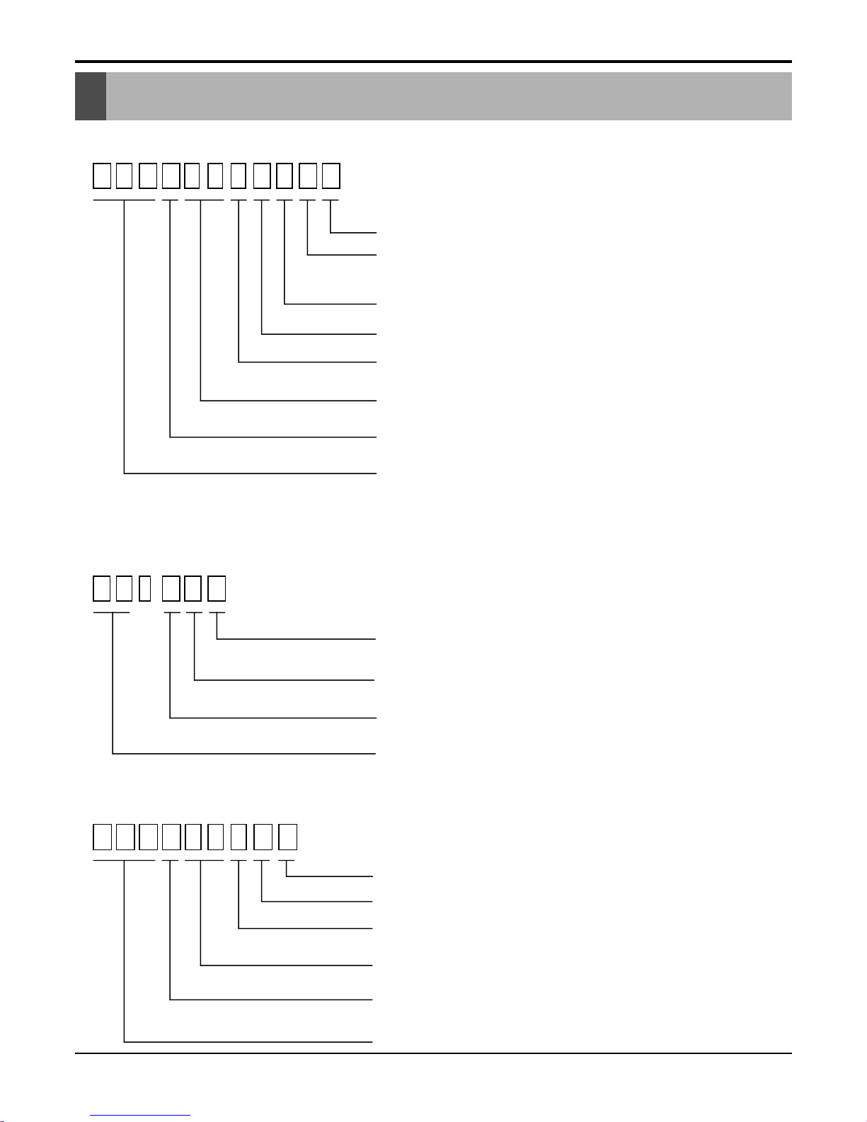
A T N H 1 8 6 E L A A
Serial Number
Functions
A : Basic C : Plasma Air Purifier(Optional)
Look : Basic
Chassis Name
Electrical Ratings
6:1Ø,220-240V,50Hz 8:3 Ø,380-415V,50Hz
Nominal Cooling Capacity in Btu/h
Ex) 18 -> 18,000 Btu/h 48 -> 48,000 Btu/h
Model Type
C: Cooling Only H: Heat Pump
R410A Universal Indoor Unit
ATN : Universal Ceiling Cassette Type Indoor Unit
ABN : Universal Ceiling Concealed Duct Type Indoor Unit
AVN : Universal Ceiling & Floor Type Indoor Unit
A U U H 1 8 6 A
Serial Number
Low Ambinent(Optional)
Electric Standard (Phase, Volts, Freq)
6:1Ø,220-240V,50Hz 8:3Ø,380-415V,50Hz
Nominal Cooling Capacity in Btu/h
Model Type
C : Cooling Only H : Heat Pump
R410A Universal Outdoor Unit
B
P T - H E A
Functions
A: Basic C:For Indoor Unit with Plasma Air Purifier.(Optional)
Indoor Unit Chassis
D: D Chassis E: E Chassis F: F Chassis
Model Type
C : Cooling Only H : Heat Pump
Decoration Panel of Ceiling Cassette Type Indoor Unit
2.1 Indoor Units
Model Number Nomenclature
Safety Precautions
Service Manual 5
Safety Precautions
To prevent injury to the user or other people and property damage, the following instructions must
be followed.
■ Incorrect operation due to ignoring instruction will cause harm or damage. The seriousness is
classified by the following indications.
■ Meanings of symbols used in this manual are as shown below.
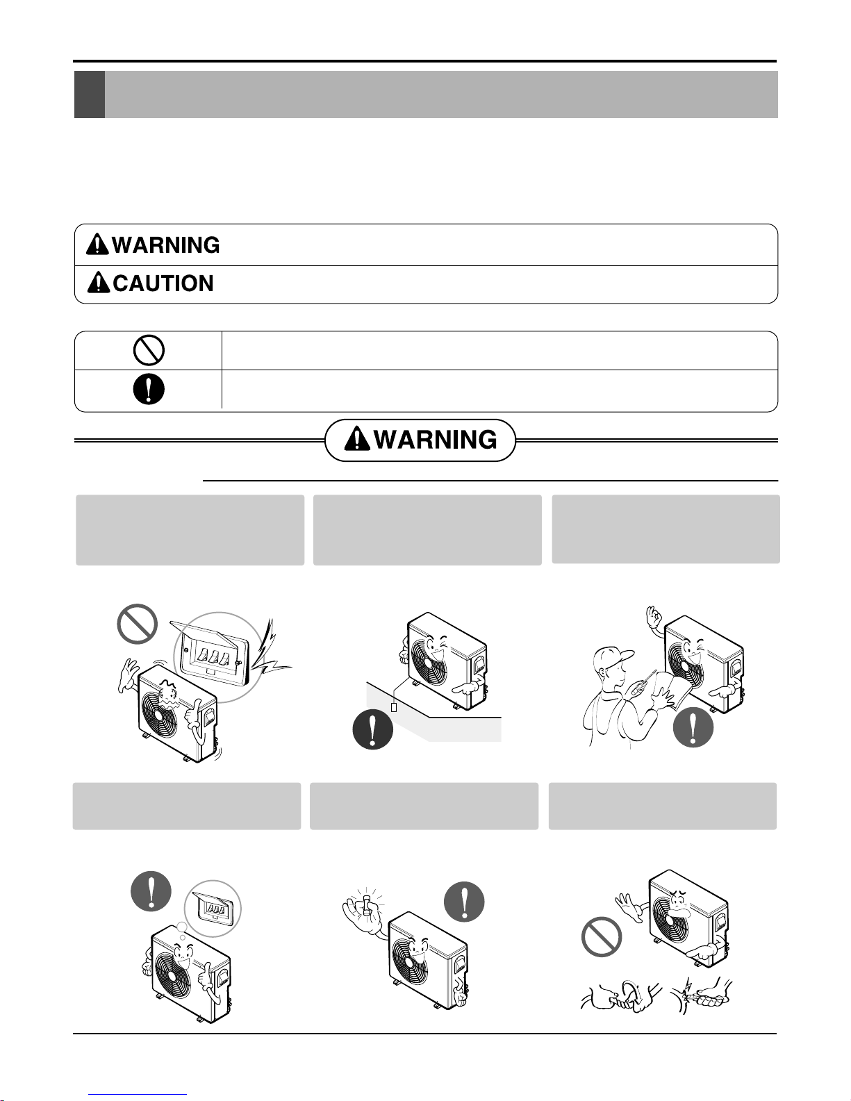
This symbol indicates the possibility of death or serious injury.
This symbol indicates the possibility of injury or damage to properties only.
■ Installation
Be sure not to do.
Be sure to follow the instruction.
Do not use a defective or underrated circuit breaker. Use this
appliance on a dedicated circuit.
• There is risk of fire or electric
shock.
Always ground the product.
• There is risk of fire or electric
shock.
Install the panel and the cover
of control box securely.
• There is risk of fire or electric
shock.
Always install a dedicated circuit and breaker.
• Improper wiring or installation may
cause fire or electric shock
Use the correctly rated breaker or fuse.
• There is risk of fire or electric
shock.
Do not modify or extend the
power cable.
• There is risk of fire or electric
shock.
Safety Precautions
6 Universal System Air Conditioner
■ Operational
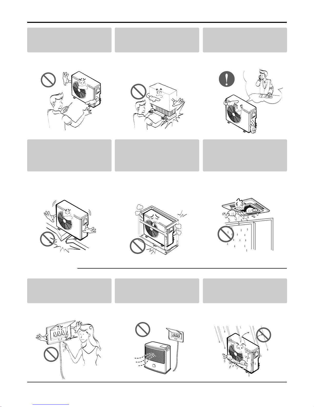
Do not install, remove, or reinstall the unit by yourself
(customer).
• There is risk of fire, electric shock,
explosion, or injury.
Be cautious when unpacking
and installing the product.
• Sharp edges could cause injury.
Be especially careful of the case
edges and the fins on the condenser and evaporator.
For installation, always contact the dealer or an
Authorized Service Center.
• There is risk of fire, electric shock,
explosion, or injury.
Do not install the product on a
defective installation stand.
• It may cause injury, accident, or
damage to the product.
Be sure the installation area
does not deteriorate with age.
• If the base collapses, the air conditioner could fall with it, causing
property damage, product failure,
and personal injury.
Do not let the air conditioner
run for a long time when the
humidity is very high and a
door or a window is left open.
• Moisture may condense and wet or
damage furniture.
Do not touch(operate) the
product with wet hands.
• There is risk of fire or electrical
shock.
Do not place a heater or other
appliances near the power
cable.
• There is risk of fire or electric
shock.
Do not let electric parts of the
product get wet.
• There is risk of fire, failure of the
product, or electric shock.
Safety Precautions
Service Manual 7
■ Installation
Do not open the inlet grill of the product during
operation. (Do not touch the electrostatic filter,
if the unit is so equipped.)
• There is risk of physical injury, electric shock, or product failure.
Be cautious that water could not enter the
product.
• There is risk of fire, electric shock, or product damage.
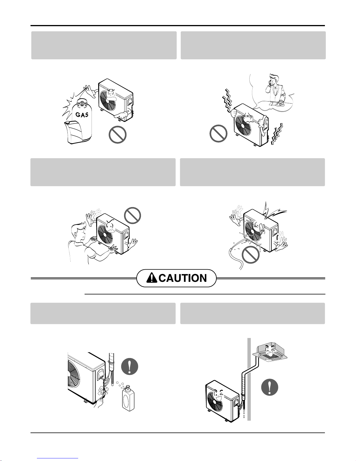
Always check for gas (refrigerant) leakage after
installation or repair of product.
• Low refrigerant levels may cause failure of product.
Install the drain hose to ensure that water is
drained away properly.
• A bad connection may cause water leakage.
Do not store or use flammable gas or combustibles near the product.
• There is risk of fire or failure of product.
If strange sounds, or small or smoke comes
from product. Turn the breaker off or disconnect the power supply cable.
• There is risk of electric shock or fire.
Gasolin
Safety Precautions
8 Universal System Air Conditioner
Keep level even when installing the product.
• To avoid vibration or water leakage.
Use two or more people to lift and transport
the product.
• Avoid personal injury.
Use a soft cloth to clean. Do not use harsh
detergents, solvents, etc.
• There is risk of fire, electric shock, or damage to the
plastic parts of the product.
Do not touch the metal parts of the product
when removing the air filter. They are very
sharp!
• There is risk of personal injury.
Do not step on or put anyting on the product.
(outdoor units)
• There is risk of personal injury and failure of product.
Do not insert hands or other objects through
the air inlet or outlet while the product is operated.
• There are sharp and moving parts that could cause
personal injury.
90˚
Wax
Thinner
■ Operational
Features & Benefits
Service Manual 9
Environment Friendly Refrigerant :
- LG Ceiling Cassette Air Conditioners uses environment friendly refrigerant, which don't do any harm to
the environment.
Jet Cool :
-In this mode, quick and fast cooling is done. Cold and
high velocity air is supplied to the room till the indoor
temperature reaches 18°C. The unit will continue to
run in jet cool mode till the Indoor temperature reaches 18°C.
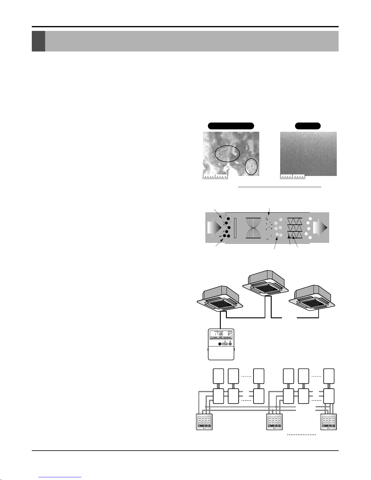
Energy Saving Gold Fin :
- Heat Exchanger fins are coated with anticorrosive &
hydrophilic layers. It prevents the corrosion of heat
exchanger. Fins remain as new even after long time
of operation and maintains efficiency of heat
exchanger. It also saves power & maintenance Cost.
Plasma Air Purifier :
- It removes not only microscopic contaminants &
dust, but also house mites, pollen, and pet fur to help
preventing allergic diseases like asthma.It provides
odor free, dust free and allergy free air.
Group Control :
- It enables to control as much as 16 units with the
help of one wired remote controller. All the units will
follow same setting of temperature & other sub functions.
Central Control :
- It enables to control 16 x 8 = 128 units with the help
of 8 controllers. All units can be put on and off from
one Central Room. For Setting Temperature, Fan
Speed and other sub functions, access the respective LCD wired remote controller of each unit.
Uncoated Aluminum Gold fin
10mm10mm 10mm10mm
Salt Spray Test Result : After 360 hours
[ Test Standard: ASTM B-117, KS D 9502 ]
Pitting Corrosion
10mm 10mm
IonizerPre-filter
Dust particles
dusts
Odour
Dust
electrode
discharge
Odor molecule
+6.5KV
discharge
aluminum coated
electrode(-)
(3.25KV discharge)
Generating
plasma
+
+
+
+
+
Dusts Collection
Polluted
Air
Purified
fresh Air
10mm 10mm
1216........
........
Main
PCB
Controller
# 1
Controller
# 2
Controller
# 8
M
1
Sub
1
M
2
Sub
2
M
16
Sub
16
M
17
Sub
17
M
18
Sub
18
M
128
Sub
128
Features & Benefits
Features & Benefits
10 Universal System Air Conditioner
71
Vane 2
Swirl Swing(New)4- Open(Conventional)
Swirl Swing(New)4- Open(Conventional)
2.4% 4.8%100% Improved
Comparison of Air Flow Types
Comparison of Floor
Temp. Distribution(20°C)
Vane 1 Close OpenOpen
Open
Open
Open
Close CloseOpen
Vane 3 Close Open Close CloseOpen
OpenOpen Close CloseOpen
Vane 2
OpenOpen
Time
Close CloseOpen
Vane 4
Vane 1
Vane 3
Vane 2
Time
Vane 4
Vane 3
Vane 4
Vane 1
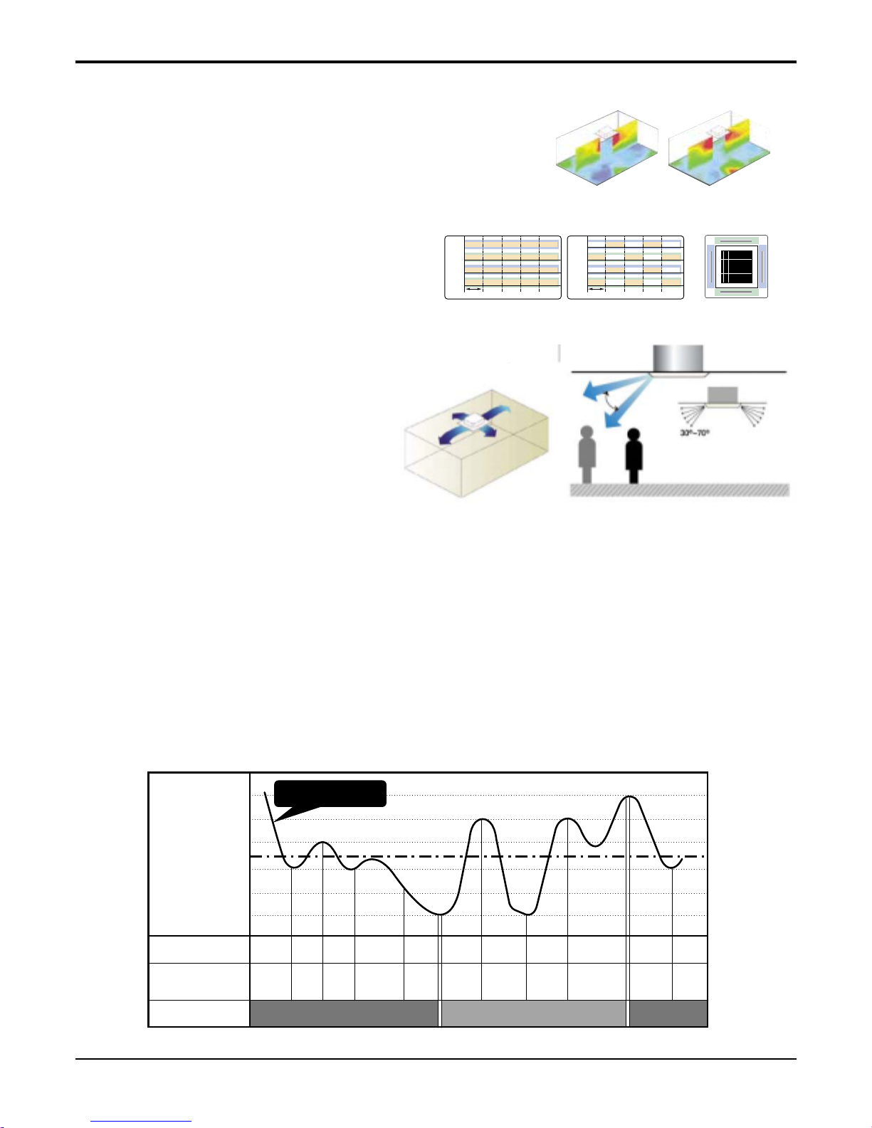
Swirl Swing(For Ceiling Cassette):
- It is the function for comfort cooling/heating operation.
- The diagonal two louvers are opened the
more larger than the other louvers.
After one minute, it is opposite.
Space Control (For Ceiling Cassette):
Vanes angle can be controlled by pair, considering its
installation environment.
- For example direct drafts can be annoying, leading
to discomfort and reduced productivity vane control
helps to eliminate this problem.
- Easily controlled by wired remote control.
- Air Flow can be controlled easily regarding any
space environment.
Auto Restart Operation :
- Whenever there is electricity failure to the unit, and after resumption of the power, unit will start in the same
mode prior to the power failure. Memorized condition are on / off condition, operating mode (cooling/heating),
set temperature and fan speed.The unit will memorize the above conditions and start with same memorized
condition.
Two Thermistor Control :
- There may be a significant difference between the temperature taken at the installed product and indoor temperature. Two thermistor control provides option to control temperature by referring any of the two temperatures. With the help of the slide switch at the back of the LCD wired remote controller, selection of the desired
thermistor for controlling the unit can be done. One thermistor is in the Indoor unit & the other one is in the
LCD wired remote.
Auto Changeover :
- While starting the unit it first senses the indoor temperature & starts the unit either in the cooling or in heating
mode, depending upon the indoor temperature. Range of operation is Setting Temp.± 2°C.
+2˚C
+1˚C
+0.5˚C
Setting Temp.
COMP
Cooling CoolingHeating
on
Set
Mode
Set
Mode
Set
Mode
Set
Mode
Low/
Stop
Low/
Stop
Set
Mode
off
Low Low LowStop
off off off off offon on on on
CYCLE
Indoor
FAN
-0.5˚C
-1˚C
-2˚C
Inside Temp
Features & Benefits
Service Manual 11
Defrost / Deicing :
- In the heating mode, it prevents the ice formation on the outdoor unit. The heating cycle is reversed to the
cooling cycle to defrost the evaporator pipe of the outdoor unit. While defrost cycle, the compressor is on and
indoor fan, outdoor fan and 4-way valve are off.
Low Ambient Control:
- If the outdoor temperature drops below certain temperature, liquid back to the compressor is prevented
by reducing outdoor fan speed. It can prevent frosting of evaporator and keep cooling operation on.
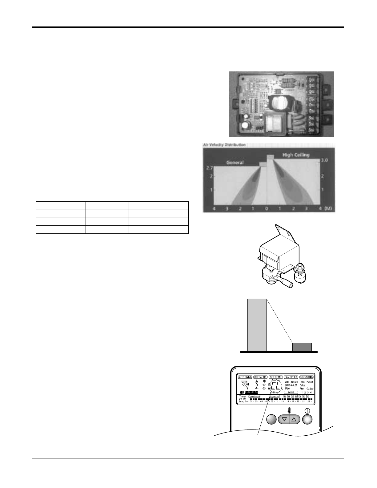
High Ceiling Operation(For Ceiling Cassette)
- According to the height of ceiling installation, it provides variability of indoor fan motor rpm. If the height
of installation is low then you can adjust low rpm of
indoor fan motor. On the other hand if the height of
the installation is high you can adjust high rpm of
indoor fan motor. Selection of speed can be done by
slide switch at the back of the LCD wired remote.
ex:
Water Drain Pump :
- In some of the places natural drainage is not possible. For such places drain pump is very useful. It
removes condensed water from the unit.
Time Delay Safety Function :
- It delays restarting of the compressor by three minutes thereby preventing damage to the compressor.
Zero Standby Power:
- Due to SMPS (Switching Modulation Power Supply)
technology, there is almost zero power consumption
in the standby mode.
Child Lock Function:
-It prevents the children or others from tampering the
control buttons. Unit can be controlled by the wireless
remote controller. This can be easily set by pressing
timer key & Min key simultaneously. After child lock is
set, pressing any key will displaye CL on the LCD for
3 seconds and all the keys will be ineffective.
5~6W
Others LG
0.5W
CHILD LOCK
-Display
Selection Height RPM
Lower 2.4m 700/600/500
Standard 2.7m 750/650/550
Higher 3.0m 800/700/600
Features & Benefits
12 Universal System Air Conditioner
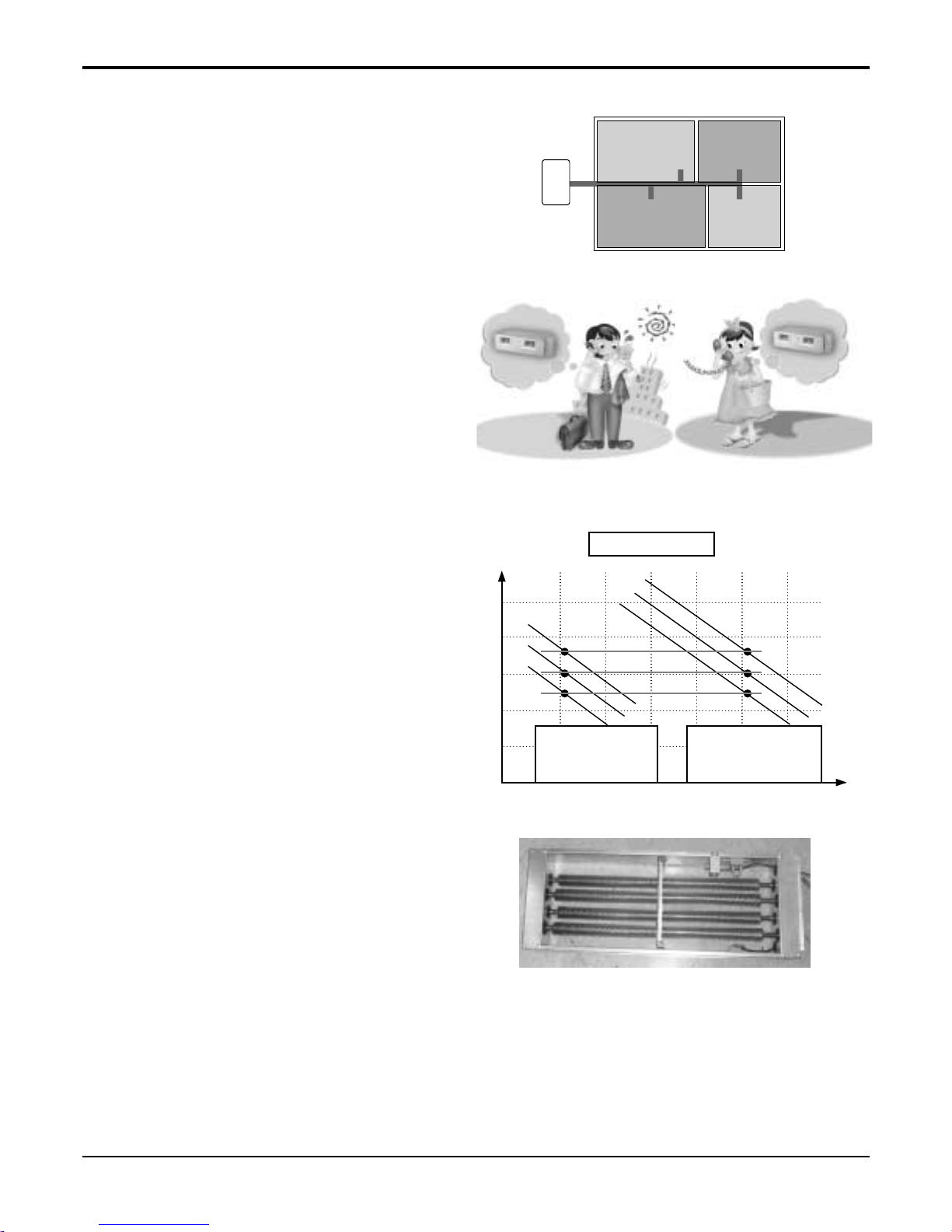
Zone Control:
- It controls the temperature of each zone. Opening
or closing of the damper is controlled by sensing
the temperature of each zone. In the cooling mode,
if the temperature of a particular zone is lower than
set temperature then the damper is closed. On the
other hand if the temperature of a particular zone
is higher then the set temperature damper is open
to provide cooling to the zone & vice versa in the
heating mode.
Tele Control :
- It provides you ease of control. Air conditioner can
be switched on/off by the telephone. It saves time
& energy.
E.S.P. Control:
- Generally, when External Static Pressure increases air volume decreases. But by controlling the
phase of motor while installing the product, E.S.P.
is controlled from 8~10mm Aq, linearly. E.S.P. control provides required constant air volume irrespective of ESP change. Desired ESP can also be set
through LCD wired remote. Setting of the desired
ESP gives required combination of ESP and airflow.
Electric Heater:
- Electric Heater can be used to provide heat in
addition to cycle heat. It also provide & quick heating. It can also work as a stand alone heater with
only fan operation.
Self Diagnosis Function:
- This function provides diagnosis of the unit. An
error code will be displayed on the LCD wired
remote controller & diagnosis can be done as per
the code indication. The same is also printed on
key cover of the LCD wired remote controller.
ON
ONON OFF
OFF
OFFOFF
In Advance by Telephone
Before Coming Home...
In case of Going out
Without Turning off the
Air Conditioner...
Zone A Zone B
Zone DZone C
Air volume
2 4 6 8 10 12
E.S.P Control
Air volume
at 2 mmAq.
L
L
M
H
M
H
Air volume
at 10 mmAq.
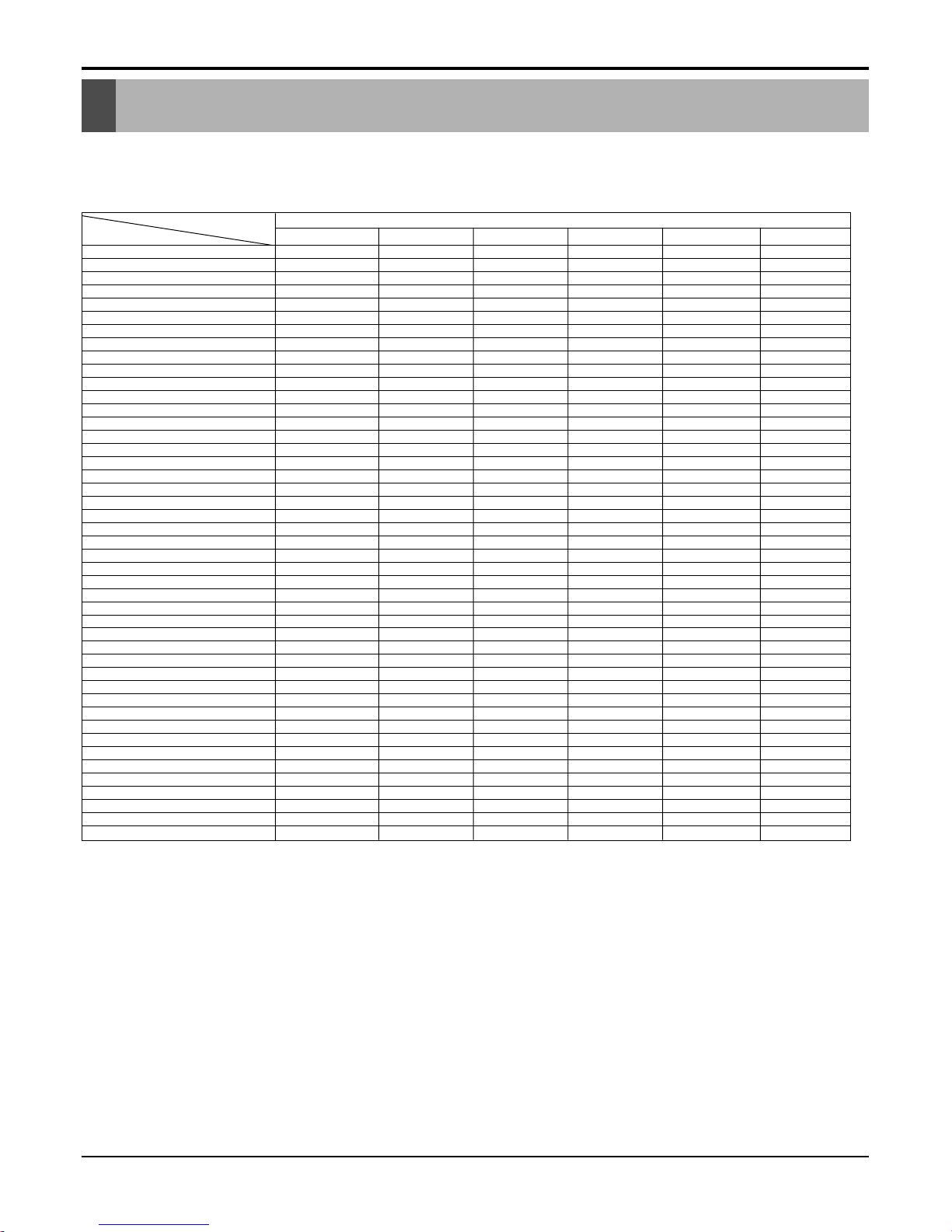
List of Functions
Service Manual 13
1 Ceiling Cassette
Model Ceiling Cassette
Features
Air Discharge Outlet 4 4 4 4 4 4
Airflow Direction control (left & right) - - - - - Airflow Direction control (up & down) Auto Auto Auto Auto Auto Auto
Airflow Steps(Fan / Cool /Heat) 3/4/- 3/4/- 3/4/- 3/4/3 3/4/3 3/4/3
Auto Changeover - - - o o o
Auto Operation o o o o o o
Auto Restart Operation o o o o o o
Auto Swing o o o o o o
Central Control Accessory Accessory Accessory Accessory Accessory Accessory
CHAOS Wind (Auto wind) - - - - - Child Lock Function o o o o o o
Cooling & Fan Operation o o o o o o
Coolling, heating & Fan Operation - - - o o o
Defrost / Deicing - - - o o o
Deodorizing Filter - - - - - Drain Pump o o o o o o
E.S.P. Control - - - - - Electric Heater - - - - - Energy Saving Gold Fin Optional Optional Optional Optional Optional Optional
Environment Friendly Refrigerant o o o o o o
Fire Alarm Function - - - - - Forced Operation o o o o o o
Group Control o o o o o o
High Ceiling Operation o o o o o o
Hot Start - - - o o o
Jet Cool o o o o o o
Low Ambient Control Optional Optional Optional Optional Optional Optional
Plasma Air Purifier Optional Optional Optional Optional Optional Optional
Prefilter(Washable / Anti-fungus) o o o o o o
Restart Delay (3-minutes) o o o o o o
Self Diagnosis o o o o o o
Sleep Mode o o o o o o
Soft Dry Operation o o o o o o
Swirl Swing o o o o o o
Tele Control - - - - - Temperature Control o o o o o o
Test Function o o o o o o
Time Delay Safety function o o o o o o
Timer (weekly) o o o o o o
Two Thermistor Control o o o o o o
Space Control o o o o o o
Wired LCD Remote Controller o o o o o o
Wireless Remote Controller o o o o o o
Zero Standby Power o o o o o o
Zone Control - - - - - -
ATNC-EL ATNC-FL ATNC-DL ATNH-EL ATNH-FL ATNH-DL
Notes :
O : Basic
Optional : Factory-Installed
Accessory : Field-Installed
- : Not available on this system
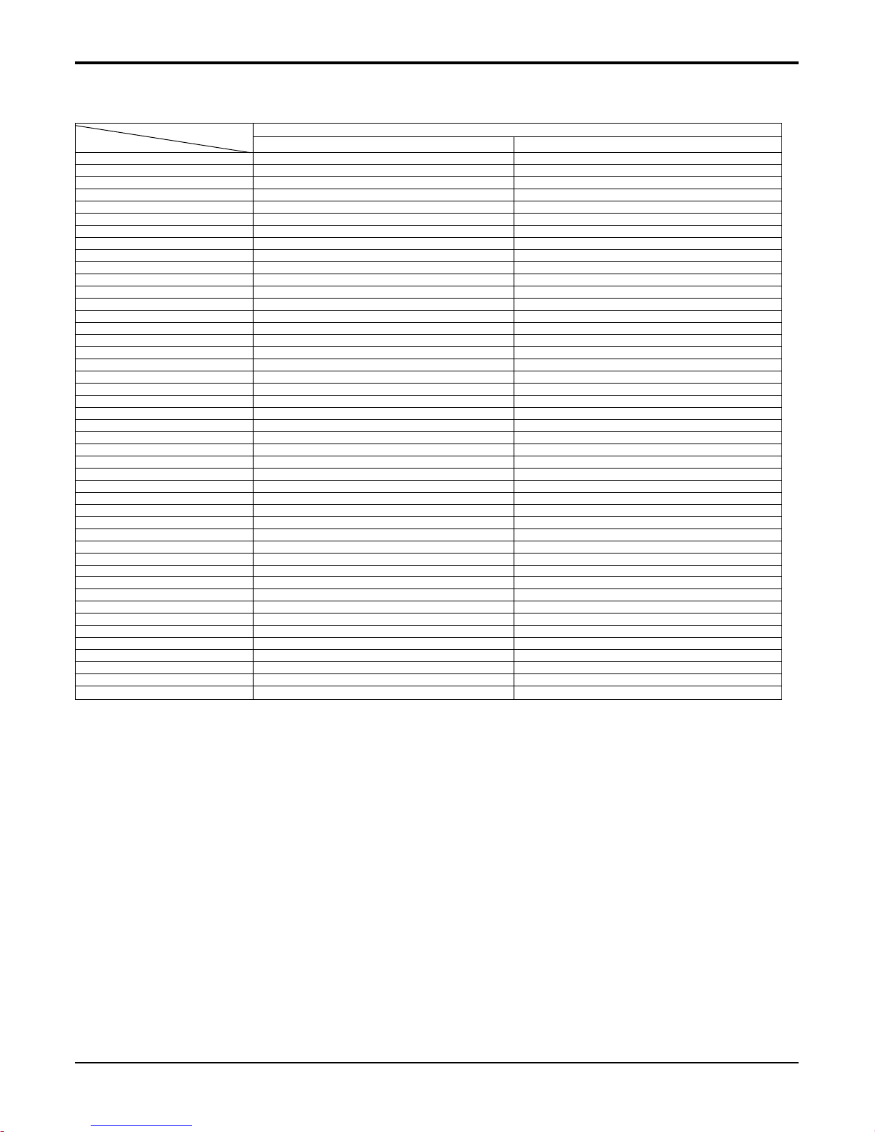
List of Functions

List of Functions
14 Universal System Air Conditioner
2 Ceiling Concealed Duct
Model Ceiling Concealed Duct
Features
Discharge Outlet
Airflow Direction control (left & right)
Airflow Direction control (up & down)
Airflow Steps(Fan / Cool /Heat)
Auto Changeover
Auto Operation
Auto Restart Operation
Auto Swing
Central Control
CHAOS Wind (Auto wind)
Child Lock Function
Cooling & Fan Operation
Coolling, heating & Fan Operation
Defrost / Deicing
Deodorizing Filter
Drain Pump
E.S.P. Control
Electric Heater
Energy Saving Gold Fin
Environment Friendly Refrigerant
Fire Alarm Function
Forced Operation
Group Control
High Ceiling Operation
Hot Start
Jet Cool
Low Ambient Control
Plasma Air Purifier
Prefilter(Washable / Anti-fungus)
Restart Delay (3-minutes)
Self Diagnosis
Sleep Mode
Soft Dry Operation
Swirl Swing
Tele Control
Temperature Control
Test Function
Time Delay Safety function
Timer (weekly)
Two Thermistor Control
Space Control
Wired LCD Remote Controller
Wireless Remote Controller
Zero Standby Power
Zone Control
ABNC-HL ABNC-GL ABNC-EL ABNH-HL ABNH-GL ABNH-EL
Notes :
O : Basic
Optional : Factory-Installed
Accessory : Field-Installed
- : Not available on this system
------
------
------
3/3/- 3/3/- 3/3/- 3/3/3 3/3/3 3/3/3
---ooo
oooooo
oooooo
------
Accessory Accessory Accessory Accessory Accessory Accessory
-----oooooo
oooooo
---ooo
---ooo
------
Accessory Accessory Accessory Accessory Accessory Accessory
oo-oo-
- - - Accessory Accessory Accessory
Optional Optional Optional Optional Optional Optional
oooooo
-----oooooo
oooooo
------
---ooo
------
Optional Optional Optional Optional Optional Optional
Accessory Accessory Accessory Accessory Accessory Accessory
oooooo
oooooo
oooooo
oooooo
oooooo
------
Accessory Accessory Accessory Accessory Accessory Accessory
oooooo
oooooo
oooooo
oooooo
oooooo
----oooooo
Accessory Accessory Accessory Accessory Accessory Accessory
oooooo
Accessory Accessory Accessory Accessory Accessory Accessory
List of Functions
Service Manual 15
3 Ceiling & Floor
Model Ceiling Concealed Duct
Features
Discharge Outlet
Airflow Direction control (left & right)
Airflow Direction control (up & down)
Airflow Steps(Fan / Cool /Heat)
Auto Changeover
Auto Operation
Auto Restart Operation
Auto Swing
Central Control
CHAOS Wind (Auto wind)
Child Lock Function
Cooling & Fan Operation
Coolling, heating & Fan Operation
Defrost / Deicing
Deodorizing Filter
Drain Pump
E.S.P. Control
Electric Heater
Energy Saving Gold Fin
Environment Friendly Refrigerant
Fire Alarm Function
Forced Operation
Group Control
High Ceiling Operation
Hot Start
Jet Cool
Low Ambient Control
Plasma Air Purifier
Prefilter(Washable / Anti-fungus)
Restart Delay (3-minutes)
Self Diagnosis
Sleep Mode
Soft Dry Operation
Swirl Swing
Tele Control
Temperature Control
Test Function
Time Delay Safety function
Timer (weekly)
Two Thermistor Control
Space Control
Wired LCD Remote Controller
Wireless Remote Controller
Zero Standby Power
Zone Control
AVNC-BL AVNH-BL
Notes :
O : Basic
Optional : Factory-Installed
Accessory : Field-Installed
- : Not available on this system
12
Manual Manual
Auto Auto
3/3/- 3/3/3
-o
oo
oo
oo
Accessory Accessory
oo
-oo
-o
-o
--
--
--
--
Optional Optional
oo
-oo
--
--
-o
--
Optional Optional
-oo
oo
oo
oo
oo
--
-oo
oo
oo
--
--
--
--
o (LCD) o (LCD)
--
--
Function of Remote Control
16 Universal System Air Conditioner
ON OFF
SET
CANCEL
Signal Fransmitter
Wall Mounted type
(Chaos)
Cassette Type
(Auto)
Heat Pump
Model
Cooling Model
56
1
3
10
11
12
13
4
7
8
9
2
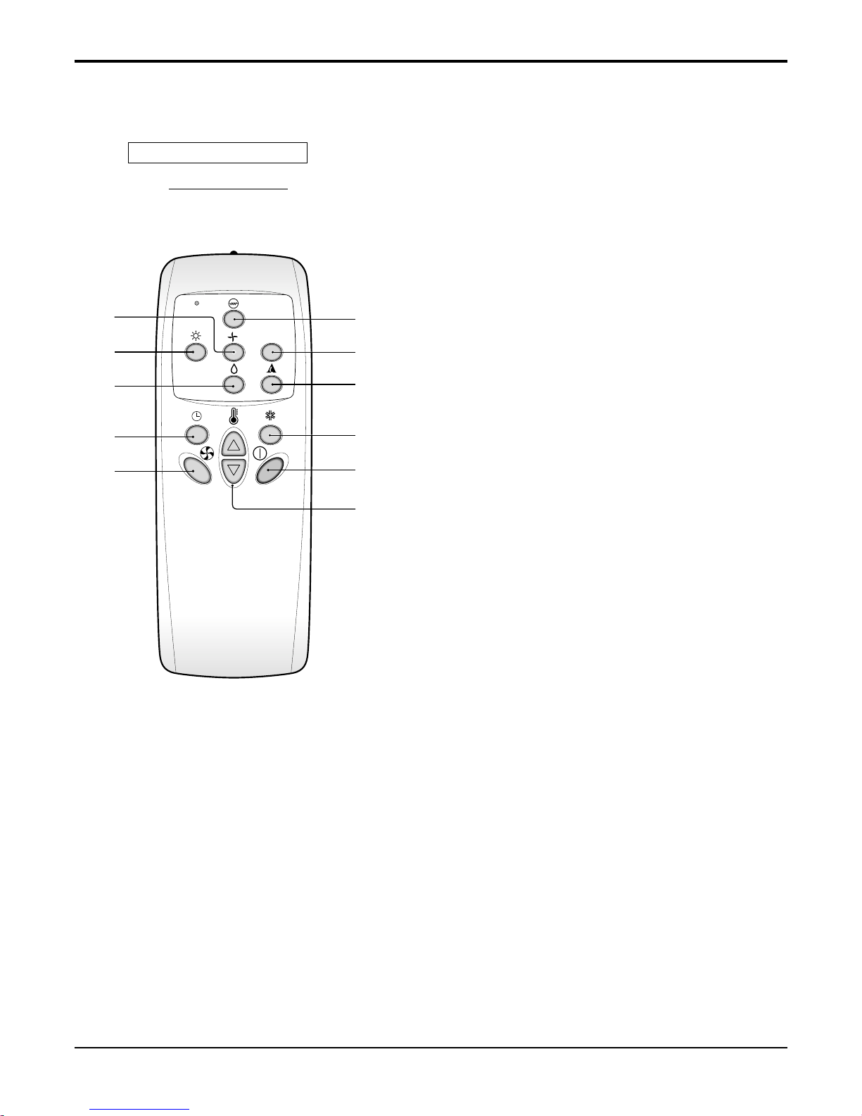
1 START/STOP BUTTON
Operation starts when this button is pressed and stops
when the button is pressed again.
2 OPERATION MODE SELECTION BUTTON
Used to select the operation mode.
3
ROOM TEMPERATURE SETTING BUTTONS
Used to select the room temperature.
4 INDOOR FAN SPEED SELECTOR
Used to select fan speed in four steps low, medium, high,
or CHAOS.
5 JET COOL
Used to start or stop the speed cooling. (Speed cooling
operates super high fan speed in cooling mode.)
6 CHAOS/AUTO SWING BUTTON
Used to stop or start louver movement and set the desired
up/down airflow direction
.
7 ON/OFF TIMER BUTTONS
Used to set the time of starting and stopping operation.
8 TIME SETTING BUTTONS
Used to adjust the time.
9 TIMER SET/CANCEL BUTTONS
Used to set the timer when the desired time is
obtained and to cancel the Timer operation.
10 SLEEP MODE AUTO BUTTON
Used to set Sleep Mode Auto operation.
11 AIR CIRCULATION BUTTON
Used to circulate the room air without cooling or
heating (turns indoor fan on/off).
12
ROOM TEMPERATURE CHECKING BUTTON
Used to check the room temperature.
13 RESET BUTTON
Used prior to resetting time or after replacing batteries.
1. Wireless LCD Remote Control(Ceiling & Floor models)
Function of Remote Control

Function of Remote Control
Service Manual 17
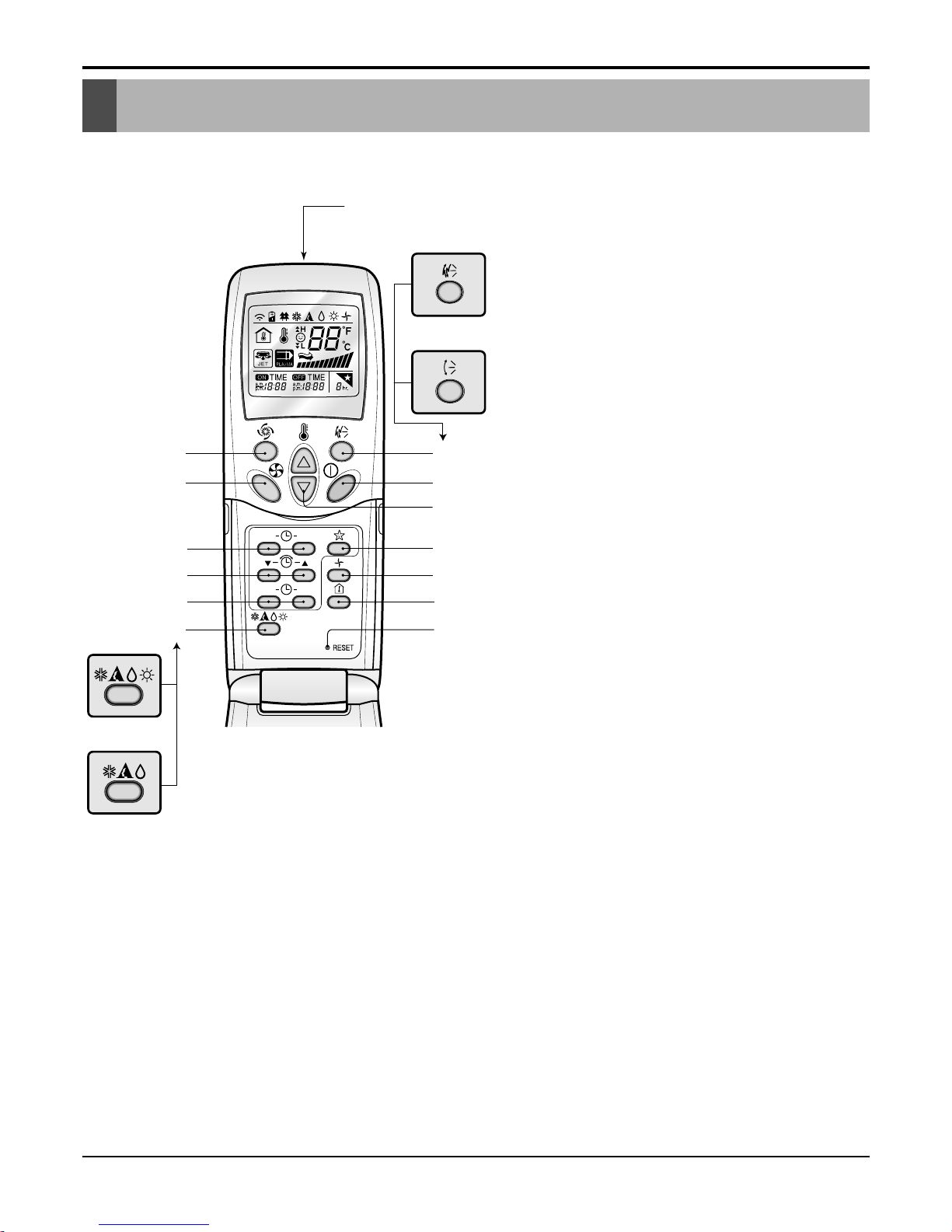
2. Wireless LCD Remote Control(Ceiling Cassette models)
1
OPERATION DISPLAY
Displays the operation conditions.
2
ON/OFF BUTTON
Operation starts when this button is pressed and stops when
the button is pressed again.
3
JET COOL BUTTON
Used to select jet cool mode.
4
ON/OFF TIMER BUTTONS
Used to set the time of starting and stopping operation.
5
TIME SETTING BUTTONS
Used to adjust the time.
6
TIMER SET/CANCEL BUTTONS
Used to set the timer when the desired time is obtained and
to cancel the Timer operation.
7
AIR SWING BUTTON
Used to swing up and down.
8
SLEEP MODE BUTTON
Used to set Sleep Mode Auto operation.
9
AIR CIRCULATION BUTTON
Used to circulate the room air without cooling or heating
(turns indoor fan on/off).
10
ROOM TEMPERATURE CHECKING BUTTON
Used to check the room temperature.
11
RESET BUTTON
Used prior to resetting time or after replacing batteries.
12
INDOOR FAN SPEED SELECTOR
Used to select fan speed in four steps-low, medium, high,
or CHAOS.
13
ROOM TEMPERATURE SETTING BUTTONS
Used to select the room temperature.
14
ORERATION MODE SELECTION BUTTON
Used to select the operation mode.
15
PLASMA AIR CLEAN BUTTON(OPTIONAL)
ON OFF
SET
CANCEL
PLASMA
Signal transmitter
(Transmits the signals to the signal receptor)
1
2
7
8
9
10
15
11
4
5
6
14
3
12
13
Heat Pump
Model
Cooling Model
Flip-up door
(opened)
18 Universal System Air Conditioner
Function of Remote Control
4. Wireless LCD Remote Control(Ceiling Concealed Duct models)
A/CL
1
4
3
5
6
11
10
9
2
7
8
Remote Controller
Signal transmitter
Transmits the signals to the signal receptor.
1 FAN Operation Button
Used to circulate room air without cooling or heating.
2 Cooling Operation Button
3 Soft Dry Operation Button
Used to dehumidify without overcooling.
4 Heating Operation Button
(Heat pump model only)
5 Timer Set Button
Used to set the timer when the desired time is obtained.
Then the wired remote controller is set up to 24 hours by an
hour but the wireless remote controller is set up to 7 hours
by an hour. Therefore, if you want to set over 7 hours, use
the wired remote controller.
6 Fan Speed Button
Used to set the desired fan speed.
7 On/Off Button
Operation starts when this button is pressed, and stops
when the button is pressed again.
8
Set Temperature Button
Used to set the temperature when the desired temperature
is obtained
9
Auto Operation Button
10
Plasma Air Clean Button(Optional)
11
Electric Heater Button
(Optional: 48/60k Model only)
Used to set the Electric Heater.
Service Manual 19
Function of Remote Control
Timer Cancel
Program Week
Hour Min
Holiday
Set/Clr
RESET
Plasma
ZONE
1234
Operation unit
Humidify
JET
AUTO
AUTO SWING OPERATION
FAN SPEED
Program set
SUB FUNCTION
SET TEMP
Room Temp
HI
MED
LO
Heater
Defrost
Filter
Preheat
Out door
Time
Timer
On
Set no. Time
Off
01 03 05 07 09 11 13 15 17 19 21 23
3
10
12
14
15
11
13
18
16
2
1
Heat Pump Model
Cooling Model
5
4
6
8
9
7
17
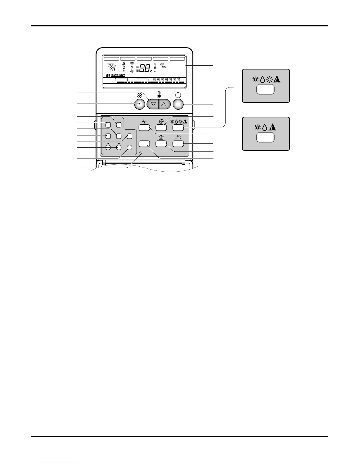
1 Operation display
Displays the operation conditions.
2 On/Off Button
Operation starts when this button is pressed, and
stops when the button is pressed again.
3 Set Temperature Button
Used to set the temperature when the desired temperature is obtained.
4 FAN Operation Button
Used to circulate room air without cooling or heating.
5 Fan Speed & Jet Cool Button
Used to set the desired fan speed and select jet
cool mode.
6 Operation Mode Selection Button
Used to select the operation mode.
• Auto Operation Mode
• Cooling Operation Mode
• Soft Dry Operation Mode
• Heating Operation Mode(except cooling model)
7 Auto Swing Button
Used to swing up and down.
8 Room Temperature Checking Button
Used to check the room temperature.
9 Plasma Air Clean Button (optional)
10 Timer Cancel Button
Used to cancel the timer.
11 Timer Set Button
Used to set the timer when the desired time is
obtained.
12 Week Button
Used to set a day of the week.
13 Program Button
Used to set the weekly timer.
14 Holiday Button
Used to set a holiday of the week.
15 Time Set Button
Used to set the time of the day and change the
time in the weekly timer Function.
16 Set and Clear Button
Used to set and clear the weekly timer.
17 Swirl Button
Used to select swirl cool mode.
18 Reset Button
Used to set the current time and clear the setting
time.
3. Wireless LCD Remote Control(Ceiling Cassette models)
20 Universal System Air Conditioner
Function of Remote Control
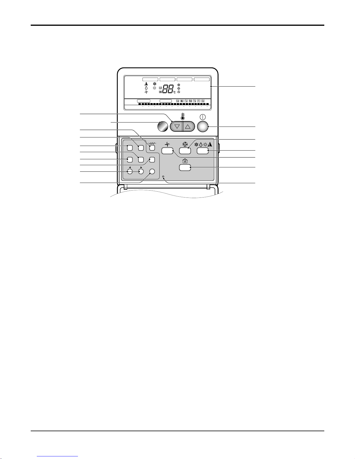
5. Wired LCD Remote Control(Ceiling Concealed Duct models)
RESET
Timer Cancel
Program Week Holiday
SET/CLR
MinHour
JET
AUTO
Humidify
ZONE
1234
AUTO SWING OPERATION
FAN SPEED
Program set
SUB FUNCTION
SET TEMP
Room Temp
HI
MED
LO
Heater
Defrost
Filter
Preheat
Out door
Timer
On
Set no. Time
Off
01 03 05 07 09 11 13 15 17 19 21 23
Time
Operation unit
3
8
5
9
10
11
12
13
14
2
1
6
4
7
16
15
Signal receptor
1 Operation display
Displays the operation conditions.
2 On/Off Button
Operation starts when this button is pressed, and
stops when the button is pressed again.
3 Set Temperature Button
Used to set the temperature when the desired temperature is obtained.
4 FAN Operation Button
Used to circulate room air without cooling or heating.
5 Electric Heater Button(optional)
Used to set the Electric Heater.
6 Fan Speed Button
Used to set desired fan speed.
7 Operation Mode Selection Button
Used to select the operation mode.
• Auto Operation Mode.
• Cooling Operation Mode.
• Soft Dry Operation Mode.
• Heating Operation Mode.(except cooling model)
8 Timer Cancel Button
Used to cancel the timer.
9 Timer Set Button
Used to set the timer when the desired time is
obtained.
10 Week Button
Used to set the day of the week.
11 Program Button
Used to set the weekly timer.
12 Holiday Button
Used to set a holiday of the week.
13 Time Setting Button
Used to set the time of the day and change the time
in the weekly timer Function.
14 Set and Clear Button
Used to set and clear the weekly timer.
15 Room Temperature Checking Button
Used to check the room temperature.
16 Reset Button
Used to set the current time and clear the setting
time.
Service Manual 21
Specifications
5,422(4,662) 5,422(4,662) 5,803(4,990)
18500 18500 19800
---
---
1840 1900 1840
8.4 8.7 8.3
1, 220-240, 50 1, 220-240, 50 1, 220-240, 50
95 94 95
2.94(2.53) 2.85(2.45) 3.15(2.71)
10.05 9.74 10.76
---
---
18~30/- 18~30/- 18~30/-
222
Capillary Tube Capillary Tube Capillary Tube
1,000(35.3), R-410A
ATNC186ELAA
, ATNC186ELCA
ABNC186HLAA AVNC186BLAA
AUUC186A/AB
PT-CEA,CEC
--
Cooling Capacity
W(kcal/h)
Btu/h
Heating Capacity
W(kcal/h)
Btu/h
Input Cooling/Heating W
Running Current Cooling/Heating A
Power Supply ø,V,Hz
Power Factor %
E.E.R Cooling
W/W(kcal/hW)
Btu/hW
C.O.P Heating
W/W(kcal/hW)
Btu/hW
Setting Temperature Range(cool/heat) °C
Dehumidification Rate l/h
Refrigerant Control
Refrigerant Charge g(oz), type
System
Indoor Unit
Outdoor Unit
Decoration Panel
Indoor Unit
ATNC186ELAA, ATNC186ELCA
ABNC186HLAA AVNC186BLAA
Output W
Model
Indoor fan motor
No. of Poles
Input W
Running Current A
Capacitor µF/Vac
Indoor Fan
Type
No. Used / Diameter EA/mm(inch)
Indoor Fan RPM
Cooling(H/M/L) rpm
Heating(H/M/L) rpm
Air Circulation Indoor (H/M/L) CMM(CFM)
Noise Level
(Sound Press,1m)
Indoor(H/M/L) dB(A)±3
Temperature Controller
Tube Size (OD) inch(mm)
Indoor Coil Fins per inch
No. of Rows & Column
Indoor inch(mm)
Dimensions (W*D*H)
Panel inch(mm)
Net Weight Indoor kg(lbs)
Nominal 1.5 Ton
Cooling Only
1. Cooling Only
3 * 2.5
4 * 0.75
1 / 4 (6.35)
5 / 8 (15.88)
7.5
50/30
ø25
-
32.3
Rotary
1
5KS225D
MATSUSHITA
5,530(18,860)
PSC
1980
RB68A or Freol Alpha68M
600
Internal
0.196(5)
21
2R 28C
67.2
IC-28640LG28P
6
120
0.54
6 / 370
Propeller
1/18.1(460)
Side Discharge
850
58(2048)
50
1 / 4 (6.35)
5 / 8 (15.88)
33.0*22.6*0.8(840*575*275)
44(98.8)
Outdoor Unit AUUC186A/AB
Locked Rotor Amp. A
Type
Quantity No.
Model
Maker
Compressor Capacity W(Btu/h)
Motor Type
Motor Input W
Oil Type
Oil Charge cc
O.L.P Type(Model Name)
Tube Size (OD) inch(mm)
Outdoor Coil Fins per inch
No. of Rows & Column
Output W
Model
Outdoor fan motor
No. of Poles
Input W
Running Current A
Capacitor µF/Vac
Type
Outdoor Fan
No. Used / Diameter EA/inch(mm)
Discharge Side / Top
Speed rpm
Air Circulation Outdoor CMM(CFM)
Noise Level
(Sound Press,1m)
Outdoor
dB(A)±3
SVC Valve
Liquid
inch(mm)
Gas
Dimensions (W*H*D) Outdoor inch(mm)
Net Weight Outdoor kg(lbs)
Others
Power Supply Cable(With Earth Cable)
No.* mm
2
Conncecting Cable(With Earth Cable)
Connecting Tube
Liquid Side inch(mm)
(ø. Socket Flare)
Gas Side inch(mm)
Length, std m
Max length/elevation m
Drain hose (ID ø)
Indoor Unit mm
Outdoor Unit mm
Notes: 1. Capacities are based on the following conditions:
Cooling: - Indoor Temperature 27°C(80.6°F) DB /19°C(66.2°F) WB
- Outdoor Temperature 35°C(95°F) DB /24°C(75.2°F) WB
- Interconnecting Piping Length 7.5m
- Level Difference of Zero.
2. Capacities are Net Capacities.
3. Due to our policy of innovation some specifications may be changed without notification.
25 118 30
IC-9630LGAD IC-13450LG13C IC-9430LGCG
644
100 180 53
0.75 0.92 0.23
2.5 / 440 6/370 1.5/370
Turbo Fan Sirocco Fan Cross Flow Fan
1/330(13.0) 2/177(7) 80(3.1)
800 / 750 / 700 1395/1356/1270 1090/990/890
---
15/14/13(530/494/459) 16.5/14.5/13(583/512/459) 14/13/12(494/459/423)
43/41/39 36/34/32 43/40/37
Thermistor Thermistor Thermistor
0.275(7) 0.275(7) 0.275(7)
21 21 20
2R 11C 2R 10C 2R 14C
22.4*22.4*10.5(570*570*269) 34.6*10.2*17.7 (880*260*450) 47.24*24.21*8.07(1200*615*205)
26.4*26.4*1.2(670*670*30) - 17(37.5) 28(61.7) 22(48.5)
Specifications

22 Universal System Air Conditioner
Specifications
3 * 2.5
4 * 0.75
1 / 4 (6.35)
5 / 8 (15.88)
7.5
50/30
ø25
-
7,034(6,048) 7,034(6,048) 7,034(6,048)
24000 24000 24000
---
---
2450 2450 2320
10.8 11 10.3
1, 220-240, 50 1, 220-240, 50 1, 220-240, 50
93 93 93
2.87(2.47) 2.87(2.47) 3.03(2.60)
9.8 9.8 10.34
---
---
18~30/- 18~30/- 18~30/-
3.3 3.3 3.3
Capillary Tube Capillary Tube Capillary Tube
1,200(42.4), R-410A
Nominal 2 Ton
Cooling Only
ATNC246FLAA
, ATNC246FLCA
ABNC246HLAA AVNC246BLAA
AUUC246A/AB
PT-CFA,CFC
--
Cooling Capacity
W(kcal/h)
Btu/h
Heating Capacity
W(kcal/h)
Btu/h
Input Cooling/Heating W
Running Current Cooling/Heating A
Power Supply ø,V,Hz
Power Factor %
E.E.R Cooling
W/W(kcal/hW)
Btu/hW
C.O.P Heating
W/W(kcal/hW)
Btu/hW
Setting Temperature Range(cool/heat) °C
Dehumidification Rate l/h
Refrigerant Control
Refrigerant Charge g(oz), type
System
Indoor Unit
Outdoor Unit
Decoration Panel
Indoor Unit
ATNC246FLAA, ATNC246FLCA
ABNC246HLAA AVNC246BLAA
Output W
Model
Indoor fan motor
No. of Poles
Input W
Running Current A
Capacitor µF/Vac
Indoor Fan
Type
No. Used / Diameter EA/mm(inch)
Indoor Fan RPM
Cooling(H/M/L) rpm
Heating(H/M/L) rpm
Air Circulation Indoor (H/M/L) CMM(CFM)
Noise Level
(Sound Press,1m)
Indoor(H/M/L) dB(A)±3
Temperature Controller
Tube Size (OD) inch(mm)
Indoor Coil Fins per inch
No. of Rows & Column
Indoor inch(mm)
Dimensions (W*D*H)
Panel inch(mm)
Net Weight Indoor kg(lbs)
Outdoor Unit AUUC246A/AB
Locked Rotor Amp. A
Type
Quantity No.
Model
Maker
Compressor Capacity W(Btu/h)
Motor Type
Motor Input W
Oil Type
Oil Charge cc
O.L.P Type(Model Name)
Tube Size (OD) inch(mm)
Outdoor Coil Fins per inch
No. of Rows & Column
Output W
Model
Outdoor fan motor
No. of Poles
Input W
Running Current A
Capacitor µF/Vac
Type
Outdoor Fan
No. Used / Diameter EA/inch(mm)
Discharge Side / Top
Speed rpm
Air Circulation Outdoor CMM(CFM)
Noise Level
(Sound Press,1m)
Outdoor dB(A)±3
SVC Valve
Liquid
inch(mm)
Gas
Dimensions (W*H*D) Outdoor inch(mm)
Net Weight Outdoor kg(lbs)
Others
Power Supply Cable(With Earth Cable)
No.* mm
2
Conncecting Cable(With Earth Cable)
Connecting Tube
Liquid Side inch(mm)
(ø. Socket Flare)
Gas Side inch(mm)
Length, std m
Max length/elevation m
Drain hose (ID ø)
Indoor Unit mm
Outdoor Unit mm
Notes: 1. Capacities are based on the following conditions:
Cooling: - Indoor Temperature 27°C(80.6°F) DB /19°C(66.2°F) WB
- Outdoor Temperature 35°C(95°F) DB /24°C(75.2°F) WB
- Interconnecting Piping Length 7.5m
- Level Difference of Zero.
2. Capacities are Net Capacities.
3. Due to our policy of innovation some specifications may be changed without notification.
40.3 118 35
OEM-3502P2 IC-13450LG13C IC-9430LGCE
644
121 180 63
0.53 0.92 0.27
4.0/ 440 6/370 1.5/370
Turbo Fan Sirocco Fan Cross Flow Fan
1/382(15) 2/177(7) 1/80(3.1)
600 / 540 / 480 1417/1350/1255 1160/1060/960
---
15/14/13(530/494/459) 18/16.5/14(636/583/494) 15/14/13(530/494/459)
43/41/38 37/35/33 45/42/39
Thermistor Thermistor Thermistor
0.275(7) 0.275(7) 0.275(7)
21 21 20
2R 12C 3R 10C 2R 14C
29.3*29.4*11.5(744*744*292) 34.6*10.2*17.7 (880*260*450) 47.24*24.21*8.07(1200*615*205)
33.5*33.5*1.18(850*850*30) - 26(57.3) 28(61.7) 22(48.5)
62
Rotary
1
GP290P
LG
6,250(24,800)
PSC
2505
FVC68D
1130
Internal
0.196(5)
21
2R 30C
67.2
IC-28640LG28P
6
120
0.54
6 / 370
Propeller
1/18.1(460)
Side Discharge
850
58(2048)
50
1 / 4 (6.35)
5 / 8 (15.88)
34.2*25.8*12.6(870*655*320)
57(125.6)

Service Manual 23
Specifications
3 *2.5
3 *0.75
1 / 4 (6.35)
5 / 8 (15.88)
7.5
50/30
ø25
-
Nominal 2.5 Ton
Cooling Only
ATNC306FLAA, ATNC306FLCA ABNC306GLAA AVNC306BLAA
AUUC306A/AB
PT-CFA,CFC - -
Cooling Capacity
W(kcal/h)
Btu/h
Heating Capacity
W(kcal/h)
Btu/h
Input Cooling/Heating W
Running Current Cooling/Heating A
Power Supply ø,V,Hz
Power Factor %
E.E.R Cooling
W/W(kcal/hW)
Btu/hW
C.O.P Heating
W/W(kcal/hW)
Btu/hW
Setting Temperature Range(cool/heat) °C
Dehumidification Rate l/h
Refrigerant Control
Refrigerant Charge g(oz), type
System
Indoor Unit
Outdoor Unit
Decoration Panel
Indoor Unit ATNC306FLAA, ATNC306FLCA ABNC306GLAA AVNC306BLAA
Output W
Model
Indoor fan motor
No. of Poles
Input W
Running Current A
Capacitor µF/Vac
Indoor Fan
Type
No. Used / Diameter EA/mm(inch)
Indoor Fan RPM
Cooling(H/M/L) rpm
Heating(H/M/L) rpm
Air Circulation Indoor (H/M/L) CMM(CFM)
Noise Level
(Sound Press,1m)
Indoor(H/M/L) dB(A)±3
Temperature Controller
Tube Size (OD) inch(mm)
Indoor Coil Fins per inch
No. of Rows & Column
Indoor inch(mm)
Dimensions (W*D*H)
Panel inch(mm)
Net Weight Indoor kg(lbs)
Outdoor Unit AUUC306A/AB
Locked Rotor Amp. A
Type
Quantity No.
Model
Maker
Compressor Capacity W(Btu/h)
Motor Type
Motor Input W
Oil Type
Oil Charge cc
O.L.P Type(Model Name)
Tube Size (OD) inch(mm)
Outdoor Coil Fins per inch
No. of Rows & Column
Output W
Model
Outdoor fan motor
No. of Poles
Input W
Running Current A
Capacitor µF/Vac
Type
Outdoor Fan
No. Used / Diameter EA/inch(mm)
Discharge Side / Top
Speed rpm
Air Circulation Outdoor CMM(CFM)
Noise Level
(Sound Press,1m)
Outdoor dB(A)±3
SVC Valve
Liquid
inch(mm)
Gas
Dimensions (W*H*D) Outdoor inch(mm)
Net Weight Outdoor kg(lbs)
Others
Power Supply Cable(With Earth Cable)
No.* mm
2
Conncecting Cable(With Earth Cable)
Connecting Tube
Liquid Side inch(mm)
(ø. Socket Flare)
Gas Side inch(mm)
Length, std m
Max length/elevation m
Drain hose (ID ø)
Indoor Unit mm
Outdoor Unit mm
Notes: 1. Capacities are based on the following conditions:
Cooling: - Indoor Temperature 27°C(80.6°F) DB /19°C(66.2°F) WB
- Outdoor Temperature 35°C(95°F) DB /24°C(75.2°F) WB
- Interconnecting Piping Length 7.5m
- Level Difference of Zero.
2. Capacities are Net Capacities.
3. Due to our policy of innovation some specifications may be changed without notification.
- 124 -
OBM-4015P2 IC-13450LG13J IC-9430LGCL
644
146 300 81
0.67 1.34 0.36
4/440 6/370 1.5/ 370
Turbo Fan Sirocco Fan Cross Flow Fan
1/382(15) 2/177(7) 80(3.1)
650 / 600 / 550 1415/1359/1290 1160/1060/960
---
19/17/15(671/600/530) 26.5/23/20(936/812/706) 18/16/14(636/564/494)
45/42/39 42/40/38 45/42/39
Thermistor Thermistor Thermistor
0.275(7) 0.275(7) 0.275(7)
21 21 20
2R 12C 3R 12C 2R 14C
29.3*29.4*11.5(744*744*292) 46.4*11.7*17.71(1180*298*450) 47.24*24.21*8.07(1200*615*205)
33.5*33.5*1.18(850*850*30) - 26(57.3) 38(83.8) 22(48.5)
8,352(7,182) 8,792(7,560) 8,352(7,182)
28500 30000 28500
---
---
2800 2950 2730
13.0 13.6 12.9
1, 220-240, 50 1, 220-240, 50 1, 220-240, 50
93 94 92
2.98(2.56) 2.98(2.56) 3.06(2.63)
10.18 10.17 10.44
---
---
18~30/- 18~30/- 18~30/-
3.5 3.5 3.5
Capillary Tube Capillary Tube Capillary Tube
1,950(68.8), R-410A
68
Rotary
1
5JS330D
MATSUSHITA
8,235(28,097)
PSC
2915
FV50S
1130
Internal
0.275(7)
18
2R 36C
67.2
IC-28640LG28P
6
120
0.54
6 / 370
Propeller
1/18.1(460)
Side Discharge
850
58(2048)
54
1 / 4 (6.35)
5 / 8 (15.88)
34.2*31.5*12.6(870*800*320)
60(132.2)

24 Universal System Air Conditioner
Specifications
5 * 3.5
4 * 1.25
1 / 4 (6.35)
5 / 8 (15.88)
7.5
50/30
ø25
-
Nominal 3 Ton
Cooling Only
ATNC368DLAA, ATNC368DLCA ABNC368GLAA
AUUC368A/AB
PT-CDA,CDC -
Cooling Capacity
W(kcal/h)
Btu/h
Heating Capacity
W(kcal/h)
Btu/h
Input Cooling/Heating W
Running Current Cooling/Heating A
Power Supply ø,V,Hz
Power Factor %
E.E.R Cooling
W/W(kcal/hW)
Btu/hW
C.O.P Heating
W/W(kcal/hW)
Btu/hW
Setting Temperature Range(cool/heat) °C
Dehumidification Rate l/h
Refrigerant Control
Refrigerant Charge g(oz), type
System
Indoor Unit
Outdoor Unit
Decoration Panel
Indoor Unit ATNC368DLAA, ATNC368DLCA ABNC368GLAA
Output W
Model
Indoor fan motor
No. of Poles
Input W
Running Current A
Capacitor µF/Vac
Indoor Fan
Type
No. Used / Diameter EA/mm(inch)
Indoor Fan RPM
Cooling(H/M/L) rpm
Heating(H/M/L) rpm
Air Circulation Indoor (H/M/L) CMM(CFM)
Noise Level
(Sound Press,1m)
Indoor(H/M/L) dB(A)±3
Temperature Controller
Tube Size (OD) inch(mm)
Indoor Coil Fins per inch
No. of Rows & Column
Indoor inch(mm)
Dimensions (W*D*H)
Panel inch(mm)
Net Weight Indoor kg(lbs)
Outdoor Unit AUUC368A/AB
Locked Rotor Amp. A
Type
Quantity No.
Model
Maker
Compressor Capacity W(Btu/h)
Motor Type
Motor Input W
Oil Type
Oil Charge cc
O.L.P Type(Model Name)
Tube Size (OD) inch(mm)
Outdoor Coil Fins per inch
No. of Rows & Column
Output W
Model
Outdoor fan motor
No. of Poles
Input W
Running Current A
Capacitor µF/Vac
Type
Outdoor Fan
No. Used / Diameter EA/inch(mm)
Discharge Side / Top
Speed rpm
Air Circulation Outdoor CMM(CFM)
Noise Level
(Sound Press,1m)
Outdoor
dB(A)±3
SVC Valve
Liquid
inch(mm)
Gas
Dimensions (W*H*D) Outdoor inch(mm)
Net Weight Outdoor kg(lbs)
Others
Power Supply Cable(With Earth Cable)
No.* mm
2
Conncecting Cable(With Earth Cable)
Connecting Tube
Liquid Side inch(mm)
(ø. Socket Flare)
Gas Side inch(mm)
Length, std m
Max length/elevation m
Drain hose (ID ø)
Indoor Unit mm
Outdoor Unit mm
Notes: 1. Capacities are based on the following conditions:
Cooling: - Indoor Temperature 27°C(80.6°F) DB /19°C(66.2°F) WB
- Outdoor Temperature 35°C(95°F) DB /24°C(75.2°F) WB
- Interconnecting Piping Length 7.5m
- Level Difference of Zero.
2. Capacities are Net Capacities.
3. Due to our policy of innovation some specifications may be changed without notification.
52.5 272
IC-1630LGPJ IC-13450LG13A
64
175 323
0.76 1.42
4 / 450 6/370
Turbo Fan Sirocco Fan
1/460(18.1) -
560 / 520 /480 1415/1359/1290
--
25/23/21(883/812/742) 32/29/26.5 (1130/1024/936)
40/38/36 42/40/38
Thermistor Thermistor
0.275(7) 0.275(7)
21 21
2R 12C 3R12C
33.0*33.0*11.3(840*840*288) 46.4*11.7 *17.71(1180*298*450)
37.4*37.4*1.2(950*950*30) 33(72.7) 38(83.8)
10,550(9,072) 10,550(9,072)
36000 36000
--
--
3760 3850
6.5 6.6
3, 380-415, 50 3, 380-415, 50
83 84
2.80(2.41) 2.73(2.35)
9.57 9.35
--
--
18~30/- 18~30/-
44
Capillary Tube Capillary Tube
2,200(77.6), R-410A
47
Scroll
1
AQ042YA
LG
10,258(35,000)
Condenser Inducted
3608
FVC68ST
1200
Internal
0.275(7)
18
2R 48C
41
IC-9625LGSY
6
80
0.35
2 / 370
Propeller
2 /15.7(400)
Side Discharge
880
105(3708)
52
1 / 4 (6.35)
5 / 8 (15.88)
35.3*41.7*12.6(870*1060*320)
85(187.3)
Service Manual 25
Specifications
5 * 3.5
4 * 1.25
3 / 8 (9.52)
3 / 4 (19.05)
7.5
50/30
ø25
-
63
Scroll
1
AR061YA
LG
14,888(50,800)
Condenser Inducted
5347
FVC68ST
1800
Internal
0.375(9.52)
18
2R 44C
72
OBM-4006P2
6
151
0.63
6 / 370
Propeller
2/18.1(460)
Side Discharge
880
105(3708)
56
3 / 8 (9.52)
3 / 4 (19.05)
35.4*48.2*14.6(900*1225*370)
93 (205.0)
Nominal 4 Ton
Cooling Only
ATNC488DLAA, ATNC488DLCA ABNC488ELAA
AUUC488A/AB
PT-CDA,CDC -
Cooling Capacity
W(kcal/h)
Btu/h
Heating Capacity
W(kcal/h)
Btu/h
Input Cooling/Heating W
Running Current Cooling/Heating A
Power Supply ø,V,Hz
Power Factor %
E.E.R Cooling
W/W(kcal/hW)
Btu/hW
C.O.P Heating
W/W(kcal/hW)
Btu/hW
Setting Temperature Range(cool/heat) °C
Dehumidification Rate l/h
Refrigerant Control
Refrigerant Charge g(oz), type
System
Indoor Unit
Outdoor Unit
Decoration Panel
Indoor Unit ATNC488DLAA, ATNC488DLCA ABNC488ELAA
Output W
Model
No. of Poles
Indoor fan motor
Input W
Running Current A
Capacitor µF/Vac
Indoor Fan
Type
No. Used / Diameter EA/mm(inch)
Indoor Fan RPM Cooling(H/M/L) rpm
Heating(H/M/L) rpm
Air Circulation Indoor (H/M/L) CMM(CFM)
Noise Level
(Sound Press,1m)
Indoor(H/M/L) dB(A)±3
Temperature Controller
Tube Size (OD) inch(mm)
Indoor Coil Fins per inch
No. of Rows & Column
Indoor inch(mm)
Dimensions (W*D*H)
Panel inch(mm)
Net Weight Indoor kg(lbs)
Outdoor Unit AUUC488A/AB
Locked Rotor Amp. A
Type
Quantity No.
Model
Maker
Compressor Capacity W(Btu/h)
Motor Type
Motor Input W
Oil Type
Oil Charge cc
O.L.P Type(Model Name)
Tube Size (OD) inch(mm)
Outdoor Coil Fins per inch
No. of Rows & Column
Output W
Model
No. of Poles
Outdoor fan motor
Input W
Running Current A
Capacitor µF/Vac
Type
Outdoor Fan
No. Used / Diameter EA/inch(mm)
Discharge Side / Top
Speed rpm
Air Circulation Outdoor CMM(CFM)
Noise Level
(Sound Press,1m)
Outdoor dB(A)±3
SVC Valve
Liquid
inch(mm)
Gas
Dimensions (W*H*D) Outdoor inch(mm)
Net Weight Outdoor kg(lbs)
Others
Power Supply Cable(With Earth Cable)
No.* mm
2
Conncecting Cable(With Earth Cable)
Connecting Tube
Liquid Side inch(mm)
(ø. Socket Flare)
Gas Side inch(mm)
Length, std m
Max length/elevation m
Drain hose (ID ø)
Indoor Unit mm
Outdoor Unit mm
Notes: 1. Capacities are based on the following conditions:
Cooling: - Indoor Temperature 27°C(80.6°F) DB /19°C(66.2°F) WB
- Outdoor Temperature 35°C(95°F) DB /24°C(75.2°F) WB
- Interconnecting Piping Length 7.5m
- Level Difference of Zero.
2. Capacities are Net Capacities.
3. Due to our policy of innovation some specifications may be changed without notification.
58.5 391
IC-1640LGPH 808555AVA-A12EX
64
195 662
1.5 2.92
6 / 400 12 / 450
Turbo Fan Sirocco Fan
1/460(18.1) -
600 / 555 / 520 1085/1024/970
--
30/28/26(1059/988/918) 40/36/30(1413/1271/1059)
43/41/39 44/42/40
Thermistor Thermistor
0.275(7) 0.375(9.52)
21 17
2R 12C 3R14C
33.0*33.0*11.3(840*840*288) 48.43*14.57*26.77(1230*370*680)
37.4*37.4*1.2(950*950*30) 33(72.7) 68(149.9)
14,067(12,096) 14,067(12,096)
48000 48000
--
--
5300 5780
9.3 9.9
3, 380-415, 50 3, 380-415, 50
82 84
2.65(2.28) 2.43(2.09)
9.05 8.3
--
--
18~30/- 18~30/-
5.5 5.5
Capillary Tube Capillary Tube
4,050(142.8), R-410A
26 Universal System Air Conditioner
Specifications
5 * 3.5
4 * 1.25
1 / 2 (12.7)
3 / 4 (19.05)
7.5
50/30
ø25
-
81
Reciprocating
1
H89A723DBVA
Bristol
17,740(60,529)
Condenser Inducted
5717
Mobil EAL Arctic 32 BC(POE)
1922
Internal
0.375(9.52)
18
2R 44C
72
OBM-4006P2
6
151
0.63
6 / 370
Propeller
2/18.1(460)
Side Discharge
880
105(3708)
58
1 / 2 (12.7)
3 / 4 (19.05)
35.4*48.2*14.6(900*1225*370)
93 (205.0)
Nominal 5 Ton
Cooling Only
ATNC608DLAA, ATNC608DLCA ABNC608ELAA
AUUC608A/AB
PT-CDA,CDC -
Cooling Capacity
W(kcal/h)
Btu/h
Heating Capacity
W(kcal/h)
Btu/h
Input Cooling/Heating W
Running Current Cooling/Heating A
Power Supply ø,V,Hz
Power Factor %
E.E.R Cooling
W/W(kcal/hW)
Btu/hW
C.O.P Heating
W/W(kcal/hW)
Btu/hW
Setting Temperature Range(cool/heat) °C
Dehumidification Rate l/h
Refrigerant Control
Refrigerant Charge g(oz), type
System
Indoor Unit
Outdoor Unit
Decoration Panel
Indoor Unit ATNC608DLAA, ATNC608DLCA ABNC608ELAA
Output W
Model
Indoor fan motor
No. of Poles
Input W
Running Current A
Capacitor µF/Vac
Indoor Fan
Type
No. Used / Diameter EA/mm(inch)
Indoor Fan RPM
Cooling(H/M/L) rpm
Heating(H/M/L) rpm
Air Circulation Indoor (H/M/L) CMM(CFM)
Noise Level
(Sound Press,1m)
Indoor(H/M/L) dB(A)±3
Temperature Controller
Tube Size (OD) inch(mm)
Indoor Coil Fins per inch
No. of Rows & Column
Indoor inch(mm)
Dimensions (W*D*H)
Panel inch(mm)
Net Weight Indoor kg(lbs)
Outdoor Unit AUUC608A/AB
Locked Rotor Amp. A
Type
Quantity No.
Model
Maker
Compressor Capacity W(Btu/h)
Motor Type
Motor Input W
Oil Type
Oil Charge cc
O.L.P Type(Model Name)
Tube Size (OD) inch(mm)
Outdoor Coil Fins per inch
No. of Rows & Column
Output W
Model
Outdoor fan motor
No. of Poles
Input W
Running Current A
Capacitor µF/Vac
Type
Outdoor Fan
No. Used / Diameter EA/inch(mm)
Discharge Side / Top
Speed rpm
Air Circulation Outdoor CMM(CFM)
Noise Level
(Sound Press,1m)
Outdoor dB(A)±3
SVC Valve
Liquid
inch(mm)
Gas
Dimensions (W*H*D) Outdoor inch(mm)
Net Weight Outdoor kg(lbs)
Others
Power Supply Cable(With Earth Cable)
No.* mm
2
Conncecting Cable(With Earth Cable)
Connecting Tube
Liquid Side inch(mm)
(ø. Socket Flare)
Gas Side inch(mm)
Length, std m
Max length/elevation m
Drain hose (ID ø)
Indoor Unit mm
Outdoor Unit mm
Notes: 1. Capacities are based on the following conditions:
Cooling: - Indoor Temperature 27°C(80.6°F) DB /19°C(66.2°F) WB
- Outdoor Temperature 35°C(95°F) DB /24°C(75.2°F) WB
- Interconnecting Piping Length 7.5m
- Level Difference of Zero.
2. Capacities are Net Capacities.
3. Due to our policy of innovation some specifications may be changed without notification.
107 389
IC-14640LGPM 808555PVA-A18EX
64
237 670
1.8 2.9
6 / 400 15 / 450
Turbo Fan Sirocco Fan
1/460(18.1) -
700 / 650 / 600 1260/1196/1125/1052
--
34/32/30(1200/1130/1059) 49/45/40/35(1730/1589/1413/1236)
50/47/43 49/46/44/42
Thermistor Thermistor
0.275(7) 0.375(9.52)
21 19
2R 12C 4R14C
33.0*33.0*11.3(840*840*288) 48.43*14.57*26.77(1230*370*680)
37.4*37.4*1.2(950*950*30) 33(72.7) 70(154.3)
15,826(13,608) 16,999(14,616)
54000 58000
--
--
6450 7060
10.5 11.4
3, 380-415, 50 3, 380-415, 50
88 89
2.40(2.07) 2.40(2.07)
8.22 8.21
--
--
18~30/- 18~30/-
6.5 6.5
Capillary Tube Capillary Tube
5,200(183.4), R-410A
Service Manual 27
Specifications
3 * 2.5
5 * 0.75
1 / 4 (6.35)
5 / 8 (15.88)
7.5
50/30
ø25
ø32
32.3
Rotary
1
5KS225D
MATSUSHITA
5,530(18,860)
PSC
1980
FV50S
600
Internal
0.275(7)
18
2R 28C
67.2
IC-28640LG28P
6
120
0.54
6 / 370
Propeller
1/18.1(460)
Side Discharge
850
58(2048)
52
1 / 4 (6.35)
5 / 8 (15.88)
34.2*25.8*12.6(870*655*320)
52(114.6)
2. Heat Pump
5,276(4,536) 5,276(4,536) 5,334(4,587)
18000 18000 18200
5,803(4,990) 5,803(4,990) 5,920(5,091)
19800 19800 20200
1,820/1,950 1,840/1,970 1,770/1,790
8.2/8.8 8.3/8.9 7.9/7.9
1, 220-240, 50 1, 220-240, 50 1, 220-240, 50
97 96 97
2.90(2.49) 2.87(2.47) 3.01(2.59)
9.89 9.78 10.28
3.19(2.56) 2.95(2.53) 3.31(2.84)
10.88 10.05 11.28
18~30/16~30 18~30/16~30 18~30/16~30
222
Capillary Tube Capillary Tube Capillary Tube
1,300(45.9), R-410A
ATNH186ELAA, ATNH186ELCA ABNH186HLAA AVNH186BLAA
AUUH186A/AB
PT-HEA,PT-HEC - -
Cooling Capacity
W(kcal/h)
Btu/h
Heating Capacity
W(kcal/h)
Btu/h
Input Cooling/Heating W
Running Current Cooling/Heating A
Power Supply ø,V,Hz
Power Factor %
E.E.R Cooling
W/W(kcal/hW)
Btu/hW
C.O.P Heating
W/W(kcal/hW)
Btu/hW
Setting Temperature Range(cool/heat) °C
Dehumidification Rate l/h
Refrigerant Control
Refrigerant Charge g(oz), type
System
Indoor Unit
Outdoor Unit
Decoration Panel
Indoor Unit ATNH186ELAA, ATNH186ELCA ABNH186HLAA AVNH186BLAA
Output W
Model
Indoor fan motor
No. of Poles
Input W
Running Current A
Capacitor µF/Vac
Indoor Fan
Type
No. Used / Diameter EA/mm(inch)
Indoor Fan RPM
Cooling(H/M/L) rpm
Heating(H/M/L) rpm
Air Circulation Indoor (H/M/L) CMM(CFM)
Noise Level
(Sound Press,1m)
Indoor(H/M/L) dB(A)±3
Temperature Controller
Tube Size (OD) inch(mm)
Indoor Coil Fins per inch
No. of Rows & Column
Indoor inch(mm)
Dimensions (W*D*H)
Panel inch(mm)
Net Weight Indoor kg(lbs)
Outdoor Unit AUUH186A/AB
Locked Rotor Amp. A
Type
Quantity No.
Model
Maker
Compressor Capacity W(Btu/h)
Motor Type
Motor Input W
Oil Type
Oil Charge cc
O.L.P Type(Model Name)
Tube Size (OD) inch(mm)
Outdoor Coil Fins per inch
No. of Rows & Column
Output W
Model
Outdoor fan motor
No. of Poles
Input W
Running Current A
Capacitor µF/Vac
Type
Outdoor Fan
No. Used / Diameter EA/inch(mm)
Discharge Side / Top
Speed rpm
Air Circulation Outdoor CMM(CFM)
Noise Level
(Sound Press,1m)
Outdoor dB(A)±3
SVC Valve
Liquid
inch(mm)
Gas
Dimensions (W*H*D) Outdoor inch(mm)
Net Weight Outdoor kg(lbs)
Others
Power Supply Cable(With Earth Cable)
No.* mm
2
Conncecting Cable(With Earth Cable)
Connecting Tube
Liquid Side inch(mm)
(ø. Socket Flare)
Gas Side inch(mm)
Length, std m
Max length/elevation m
Drain hose (ID ø)
Indoor Unit mm
Outdoor Unit mm
25 118 30
IC-9630LGAD IC-13450LG13C IC-9430LGCG
644
100 180 53
0.75 0.92 0.23
2.5 / 440 6/370 1.5/370
Turbo Fan Sirocco Fan Cross Flow Fan
1/330(13.0) 2/177(7) 1/80(3.1)
800 / 750 / 700 1395/1356/1270 1090/990/890
800 / 750 / 700 1395/1356/1270 1090/990/890
15/14/13(530/494/459) 16.5/14.5/13(583/512/459) 14/13/12(494/459/423)
43/41/39 36/34/32 43/40/37
Thermistor Thermistor Thermistor
0.275(7) 0.275(7) 0.275(7)
21 21 20
2R 11C 2R 10C 2R 14C
22.4*22.4*10.5(570*570*269) 34.6*10.2*17.7 (880*260*450) 47.24*24.21*8.07(1200*615*205)
26.4*26.4*1.2(670*670*30) - 17(37.5) 28(61.7) 22(48.5)
Notes: 1. Capacities are based on the following conditions:
Cooling: - Indoor Temperature 27°C(80.6°F) DB /19°C(66.2°F)WB
- Outdoor Temperature 35°C(95°F) DB /24°C(75.2°F)WB
- Interconnecting Piping Length 7.5m
- Level Difference of Zero.
2. Capacities are Net Capacities.
3. Due to our policy of innovation some specifications may be changed without notification.
Heating:- Indoor Temperature 20°C(68°F) DB / 15°C(59°F)WB
- Outdoor Temperature 7°C(44.6°F) DB / 6°C(42.8°F)WB
- Interconnecting Piping Length 7.5 m
- Level Difference of Zero.
Nominal 1.5 Ton
Heat Pump
28 Universal System Air Conditioner
Specifications
3 * 2.5
5 * 0.75
1 / 4 (6.35)
5 / 8 (15.88)
7.5
50/30
ø25
ø32
62
Rotary
1
GP290P
LG
6,250(24,800)
PSC
2505
FVC68D
1130
Internal
0.275(7)
18
2R 36C
67.2
IC-28640LG28P
6
120
0.54
6 / 370
Propeller
1/18.1(460)
Side Discharge
850
58(2048)
52
1 / 4 (6.35)
5 / 8 (15.88)
34.2*31.5*12.6(870*800*320)
60(132.2)
Nominal 2 Ton
Heat Pump
7,034(6,048) 7,034(6,048) 7,034(6,048)
24000 24000 24000
7,767(6,678) 7,854(6,754) 7,737(6,653)
26500 26800 26400
2,400/2,380 2,400/2,500 2,330/2,450
10.7/10.7 10.8/11.2 10.4/11.0
1, 220-240, 50 1, 220-240, 50 1, 220-240, 50
93 95 93
2.93(2.52) 2.93(2.52) 3.02(2.60)
10 10 10.3
3.26(2.80) 3.14(2.76) 3.15(2.71)
11.13 10.72 10.77
18~30/16~30 18~30/16~30 18~30/16~30
3.3 3.3 3.3
Capillary Tube Capillary Tube Capillary Tube
1,900(67.1), R-410A
ATNH246FLAA, ATNH246FLCA ABNH246HLAA AVNH246BLAA
AUUH246A/AB
PT-HFA,PT-HFC - -
Cooling Capacity
W(kcal/h)
Btu/h
Heating Capacity
W(kcal/h)
Btu/h
Input Cooling/Heating W
Running Current Cooling/Heating A
Power Supply ø,V,Hz
Power Factor %
E.E.R Cooling
W/W(kcal/hW)
Btu/hW
C.O.P Heating
W/W(kcal/hW)
Btu/hW
Setting Temperature Range(cool/heat) °C
Dehumidification Rate l/h
Refrigerant Control
Refrigerant Charge g(oz), type
System
Indoor Unit
Outdoor Unit
Decoration Panel
Indoor Unit ATNH246FLAA, ATNH246FLCA ABNH246HLAA AVNH246BLAA
Output W
Model
Indoor fan motor
No. of Poles
Input W
Running Current A
Capacitor µF/Vac
Indoor Fan
Type
No. Used / Diameter EA/mm(inch)
Indoor Fan RPM
Cooling(H/M/L) rpm
Heating(H/M/L) rpm
Air Circulation Indoor (H/M/L) CMM(CFM)
Noise Level
(Sound Press,1m)
Indoor(H/M/L) dB(A)±3
Temperature Controller
Tube Size (OD) inch(mm)
Indoor Coil Fins per inch
No. of Rows & Column
Indoor inch(mm)
Dimensions (W*D*H)
Panel inch(mm)
Net Weight Indoor kg(lbs)
Outdoor Unit AUUH246A/AB
Locked Rotor Amp. A
Type
Quantity No.
Model
Maker
Compressor Capacity W(Btu/h)
Motor Type
Motor Input W
Oil Type
Oil Charge cc
O.L.P Type(Model Name)
Tube Size (OD) inch(mm)
Outdoor Coil Fins per inch
No. of Rows & Column
Output W
Model
Outdoor fan motor
No. of Poles
Input W
Running Current A
Capacitor µF/Vac
Type
Outdoor Fan
No. Used / Diameter EA/inch(mm)
Discharge Side / Top
Speed rpm
Air Circulation Outdoor CMM(CFM)
Noise Level
(Sound Press,1m)
Outdoor dB(A)±3
SVC Valve
Liquid
inch(mm)
Gas
Dimensions (W*H*D) Outdoor inch(mm)
Net Weight Outdoor kg(lbs)
Others
Power Supply Cable(With Earth Cable)
No.* mm
2
Conncecting Cable(With Earth Cable)
Connecting Tube
Liquid Side inch(mm)
(ø. Socket Flare)
Gas Side inch(mm)
Length, std m
Max length/elevation m
Drain hose (ID ø)
Indoor Unit mm
Outdoor Unit mm
40.3 118 35
OEM-3502P2 IC-13450LG13C IC-9430LGCE
644
121 180 63
0.53 0.92 0.27
4.0/ 440 6/370 1.5/370
Turbo Fan Sirocco Fan Cross Flow Fan
1/382(15) 2/177(7) 1/80(3.1)
600 / 540 / 480 1417/1350/1255 1160/1060/960
600 / 540 / 480 1417/1350/1255 1160/1060/960
15/14/13(530/494/459) 18/16.5/14(636/583/494) 15/14/13(530/494/459)
43/41/38 37/35/33 45/42/39
Thermistor Thermistor Thermistor
0.275(7) 0.275(7) 0.275(7)
21 21 20
2R 12C 3R 10C 2R 14C
29.3*29.4*11.5(744*744*292) 34.6*10.2*17.7 (880*260*450) 47.24*24.21*8.07(1200*615*205)
33.5*33.5*1.18(850*850*30) - 26(57.3) 28(61.7) 22(48.5)
Notes: 1. Capacities are based on the following conditions:
Cooling: - Indoor Temperature 27°C(80.6°F) DB /19°C(66.2°F)WB
- Outdoor Temperature 35°C(95°F) DB /24°C(75.2°F)WB
- Interconnecting Piping Length 7.5m
- Level Difference of Zero.
2. Capacities are Net Capacities.
3. Due to our policy of innovation some specifications may be changed without notification.
Heating:- Indoor Temperature 20°C(68°F) DB / 15°C(59°F) WB
- Outdoor Temperature 7°C(44.6°F) DB / 6°C(42.8°F) WB
- Interconnecting Piping Length 7.5 m
- Level Difference of Zero.

Service Manual 29
Specifications
3 * 2.5
5 * 0.75
1 / 4 (6.35)
5 / 8 (15.88)
7.5
50/30
ø25
ø32
Nominal 2.5 Ton
Heat Pump
ATNH306FLAA, ATNH306FLCA ABNH306GLAA AVNH306BLAA
AUUH306A/AB
PT-HFA,PT-HFC - -
Cooling Capacity
W(kcal/h)
Btu/h
Heating Capacity
W(kcal/h)
Btu/h
Input Cooling/Heating W
Running Current Cooling/Heating A
Power Supply ø,V,Hz
Power Factor %
E.E.R Cooling
W/W(kcal/hW)
Btu/hW
C.O.P Heating
W/W(kcal/hW)
Btu/hW
Setting Temperature Range(cool/heat) °C
Dehumidification Rate l/h
Refrigerant Control
Refrigerant Charge g(oz), type
System
Indoor Unit
Outdoor Unit
Decoration Panel
Indoor Unit ATNH306FLAA, ATNH306FLCA ABNH306GLAA AVNH306BLAA
Output W
Model
Indoor fan motor
No. of Poles
Input W
Running Current A
Capacitor µF/Vac
Indoor Fan
Type
No. Used / Diameter EA/mm(inch)
Indoor Fan RPM
Cooling(H/M/L) rpm
Heating(H/M/L) rpm
Air Circulation Indoor (H/M/L) CMM(CFM)
Noise Level
(Sound Press,1m)
Indoor(H/M/L) dB(A)±3
Temperature Controller
Tube Size (OD) inch(mm)
Indoor Coil Fins per inch
No. of Rows & Column
Indoor inch(mm)
Dimensions (W*D*H)
Panel inch(mm)
Net Weight Indoor kg(lbs)
Outdoor Unit AUUH306A/AB
Locked Rotor Amp. A
Type
Quantity No.
Model
Maker
Compressor Capacity W(Btu/h)
Motor Type
Motor Input W
Oil Type
Oil Charge cc
O.L.P Type(Model Name)
Tube Size (OD) inch(mm)
Outdoor Coil Fins per inch
No. of Rows & Column
Output W
Model
Outdoor fan motor
No. of Poles
Input W
Running Current A
Capacitor µF/Vac
Type
Outdoor Fan
No. Used / Diameter EA/inch(mm)
Discharge Side / Top
Speed rpm
Air Circulation Outdoor CMM(CFM)
Noise Level
(Sound Press,1m)
Outdoor dB(A)±3
SVC Valve
Liquid
inch(mm)
Gas
Dimensions (W*H*D) Outdoor inch(mm)
Net Weight Outdoor kg(lbs)
Others
Power Supply Cable(With Earth Cable)
No.* mm
2
Conncecting Cable(With Earth Cable)
Connecting Tube
Liquid Side inch(mm)
(ø. Socket Flare)
Gas Side inch(mm)
Length, std m
Max length/elevation m
Drain hose (ID ø)
Indoor Unit mm
Outdoor Unit mm
- 124 -
OBM-4015P2 IC-13450LG13J IC-9430LGCL
644
146 300 81
0.67 1.34 0.36
4/440 6/370 1.5/ 370
Turbo Fan Sirocco Fan Cross Flow Fan
1/382(15) 2/177(7) 80(3.1)
650 / 600 / 550 1415/1359/1290 1160/1060/960
650 / 600 / 550 1415/1359/1290 1160/1060/960
19/17/15(671/600/530) 26.5/23/20(936/812/706) 18/16/14(636/564/494)
45/42/39 42/40/38 45/42/39
Thermistor Thermistor Thermistor
0.275(7) 0.275(7) 0.275(7)
21 21 20
2R 12C 3R 12C 2R 14C
29.3*29.4*11.5(744*744*292) 46.4*11.7 *17.71(1180*298*450) 47.24*24.21*8.07 (1200*615*205)
33.5*33.5*1.18(850*850*30) - 26(57.3) 38(83.8) 22(48.5)
Notes: 1. Capacities are based on the following conditions:
Cooling: - Indoor Temperature 27°C(80.6°F) DB /19°C(66.2°F)WB
- Outdoor Temperature 35°C(95°F) DB /24°C(75.2°F) WB
- Interconnecting Piping Length 7.5m
- Level Difference of Zero.
2. Capacities are Net Capacities.
3. Due to our policy of innovation some specifications may be changed without notification.
Heating:- Indoor Temperature 20°C(68°F) DB / 15°C(59°F)WB
- Outdoor Temperature 7°C(44.6°F) DB / 6°C(42.8°F)WB
- Interconnecting Piping Length 7.5 m
- Level Difference of Zero.
7,913(6,804) 8,411(7,232) 7,678(6,602)
27000 28700 26200
8,704(7,484) 9,232(7,938) 8,382(7,207)
29700 31500 28600
2,790/2,900 2,950/2,600 2,720/2,970
13.0/13.7 13.5/12.1 12.7/13.8
1, 220-240, 50 1, 220-240, 50 1, 220-240, 50
93 94 93
2.83(2.44) 2.85(2.45) 2.82(2.42)
9.67 9.72 9.63
3.0(2.58) 3.55(3.05) 2.86(2.46)
10.24 12.11 9.76
18~30/16~30 18~30/16~30 18~30/16~30
3.5 3.5 3.5
Capillary Tube Capillary Tube Capillary Tube
2,300(81.2), R-410A
68
Rotary
1
5JS330D
MATSUSHITA
8,235(28,097)
PSC
2915
FV50S
1130
Internal
0.275(7)
18
2R 36C
67.2
IC-28640LG28P
6
120
0.54
6 / 370
Propeller
1/18.1(460)
Side Discharge
850
58(2048)
54
1 / 4 (6.35)
5 / 8 (15.88)
34.2*31.5*12.6(870*800*320)
62(136.6)

30 Universal System Air Conditioner
Specifications
5 * 3.5
5 * 1.25
1 / 4 (6.35)
5 / 8 (15.88)
7.5
50/30
ø25
ø32
Nominal 3 Ton
Heat Pump
ATNH368DLAA, ATNH368DLCA ABNH368GLAA
AUUH368A/AB
PT-HDA,PT-HDC -
Cooling Capacity
W(kcal/h)
Btu/h
Heating Capacity
W(kcal/h)
Btu/h
Input Cooling/Heating W
Running Current Cooling/Heating A
Power Supply ø,V,Hz
Power Factor %
E.E.R Cooling
W/W(kcal/hW)
Btu/hW
C.O.P Heating
W/W(kcal/hW)
Btu/hW
Setting Temperature Range(cool/heat) °C
Dehumidification Rate l/h
Refrigerant Control
Refrigerant Charge g(oz), type
System
Indoor Unit
Outdoor Unit
Decoration Panel
Indoor Unit ATNH368DLAA, ATNH368DLCA ABNH368GLAA
Output W
Model
Indoor fan motor
No. of Poles
Input W
Running Current A
Capacitor µF/Vac
Indoor Fan
Type
No. Used / Diameter EA/mm(inch)
Indoor Fan RPM
Cooling(H/M/L) rpm
Heating(H/M/L) rpm
Air Circulation Indoor (H/M/L) CMM(CFM)
Noise Level
(Sound Press,1m)
Indoor(H/M/L) dB(A)±3
Temperature Controller
Tube Size (OD) inch(mm)
Indoor Coil Fins per inch
No. of Rows & Column
Indoor inch(mm)
Dimensions (W*D*H)
Panel inch(mm)
Net Weight Indoor kg(lbs)
Outdoor Unit AUUH368A/AB
Locked Rotor Amp. A
Type
Quantity No.
Model
Maker
Compressor Capacity W(Btu/h)
Motor Type
Motor Input W
Oil Type
Oil Charge cc
O.L.P Type(Model Name)
Tube Size (OD) inch(mm)
Outdoor Coil Fins per inch
No. of Rows & Column
Output W
Model
Outdoor fan motor
No. of Poles
Input W
Running Current A
Capacitor µF/Vac
Type
Outdoor Fan
No. Used / Diameter EA/inch(mm)
Discharge Side / Top
Speed rpm
Air Circulation Outdoor CMM(CFM)
Noise Level
(Sound Press,1m)
Outdoor dB(A)±3
SVC Valve
Liquid
inch(mm)
Gas
Dimensions (W*H*D) Outdoor inch(mm)
Net Weight Outdoor kg(lbs)
Others
Power Supply Cable(With Earth Cable)
No.* mm
2
Conncecting Cable(With Earth Cable)
Connecting Tube
Liquid Side inch(mm)
(ø. Socket Flare)
Gas Side inch(mm)
Length, std m
Max length/elevation m
Drain hose (ID ø)
Indoor Unit mm
Outdoor Unit mm
52.5 272
IC-1630LGPJ IC-13450LG13A
64
175 323
0.76 1.42
4 / 450 6/370
Turbo Fan Sirocco Fan
1/460(18.1) 560 / 520 /480 1415/1359/1290
560 / 520 /480 1415/1359/1290
25/23/21(883/812/742) 32/29/26.5 (1130/1024/936)
40/38/36 42/40/38
Thermistor Thermistor
0.275(7) 0.275(7)
21 21
2R 12C 3R12C
33.0*33.0*11.3(840*840*288) 46.4*11.7 *17.71 (1180*298*450)
37.4*37.4*1.2(950*950*30) 33(72.7) 38(83.8)
Notes: 1. Capacities are based on the following conditions:
Cooling: - Indoor Temperature 27°C(80.6°F) DB /19°C(66.2°F)WB
- Outdoor Temperature 35°C(95°F) DB /24°C(75.2°F) WB
- Interconnecting Piping Length 7.5m
- Level Difference of Zero.
2. Capacities are Net Capacities.
3. Due to our policy of innovation some specifications may be changed without notification.
Heating:- Indoor Temperature 20°C(68°F) DB / 15°C(59°F) WB
- Outdoor Temperature 7°C(44.6°F) DB / 6°C(42.8°F) WB
- Interconnecting Piping Length 7.5 m
- Level Difference of Zero.
10,550(9,072) 10,550(9,072)
36000 36000
11,606(9,979) 11,606(9,979)
39600 39600
3760/3340 3850/3330
6.5/6.0 6.6/6.0
3, 380-415, 50 3, 380-415, 50
83 84
2.80(2.41) 2.73(2.35)
9.57 9.35
3.47(2.98) 3.48(2.99)
11.85 11.89
18~30/16~30 18~30/16~30
44
Capillary Tube Capillary Tube
2,200(77.6), R-410A
47
Scroll
1
AQ042YA
LG
10,258(35,000)
Condenser Inducted
3608
FVC68ST
1200
Internal
0.275(7)
18
2R 48C
41
IC-9625LGSY
6
80
0.35
2 / 370
Propeller
2 /15.7(400)
Side Discharge
880
105(3708)
52
1 / 4 (6.35)
5 / 8 (15.88)
35.3*41.7*12.6(870*1060*320)
85(187.3)
 Loading...