

LG A5UW40GFA1 INSTALLATION MANUAL

Please read this installation manual completely before installing
the product.
Installation work must be performed in accordance with the
national wiring standards by authorized personnel only.
Please retain this installation manual for future reference after
reading it thoroughly.
MULTI
www.lg.com
Copyright © 2012 - 2020 LG Electronics Inc. All Rights Reserved.
INSTALLATION MANUAL
AIR
CONDITIONER
MFL67655701
Rev.03_111320
ENGLISH ESPAÑOL
PORTUGUÊS

TIPS FOR SAVING ENERGY
2
ENGLISH
TIPS FOR SAVING ENERGY
Here are some tips that will help you minimize the power consumption when you use the air
conditioner. You can use your air conditioner more efficiently by referring to the instructions
below:
• Do not cool excessively indoors. This may be harmful to your health and may consume more
electricity.
• Block sunlight with blinds or curtains while you are operating the air conditioner.
• Keep doors or windows closed tightly while you are operating the air conditioner.
• Adjust the direction of the air flow vertically or horizontally to circulate indoor air.
• Speed up the fan to cool or warm indoor air quickly, in a short period of time.
• Open windows regularly for ventilation as the indoor air quality may deteriorate if the air conditioner
is used for many hours.
• Clean the air filter once every 2 weeks. Dust and impurities collected in the air filter may block the
air flow or weaken the cooling / dehumidifying functions.
For your records
Staple your receipt to this page in case you need it to prove the date of purchase or for warranty
purposes. Write the model number and the serial number here:
Model number :
Serial number :
You can find them labeled on the side of each unit.
Dealer’s name :
Date of purchase :

IMPORTANT SAFETY INSTRUCTIONS
3
IMPORTANT SAFETY INSTRUCTIONS
READ ALL INSTRUCTIONS BEFORE USING THE APPLIANCE.
Always comply with the following precautions to avoid dangerous situations and ensure peak
performance of your product
WARNING
!
It can result in serious injury or death when the directions are ignored
CAUTION
!
It can result in minor injury or product damage when the directions are ignored
WARNING
!
• Installation or repairs made by unqualified persons can result in hazards to you and others.
• Installation work must be performed in accordance with the National Electric Code by qualified and
authorized personnel only.
• The information contained in the manual is intended for use by a qualified service technician familiar with
safety procedures and equipped with the proper tools and test instruments.
• Failure to carefully read and follow all instructions in this manual can result in equipment malfunction,
property damage, personal injury and/or death.
Installation
• Do not use a defective or underrated circuit breaker.
- Use the correctly rated breaker and fuse. There is risk of fire or electric shock.
• For electrical work, contact the dealer, seller, a qualified electrician, or an Authorized Service Center.
- Do not disassemble or repair the product by yourself. There is risk of fire or electric shock.
• Always ground the product as per the wiring diagram.
- Do not connect the ground wire to gas or water pipes lightening rod or telephone ground wire.
There is risk of fire or electric shock.
• Install the panel and the cover of control box securely.
- There is risk of fire or electric shock due to dust , water etc.
• Always install a dedicated circuit and breaker.
- Improper wiring or installation may cause fire or electric shock.
• Use the correctly rated breaker or fuse.
- There is risk of fire or electric shock.
• Do not modify or extend the power cable.
- If the power cable or cord has scratches or skin peeled off or deteriorated then it must be replaced.
There is risk of fire or electric shock.
• For installation, removal or reinstall , always contact the dealer or an Authorized Service Center.
- There is risk of fire, electric shock, explosion, or injury.
• Do not install the product on a defective installation stand.
- Be sure that the installation area does not deteriorate with age. It may cause product to fall.
• Never install the outdoor unit on a moving base or a place from where it can fall down.
- The falling outdoor unit can cause damage or injury or even death of a person.
• In outdoor unit the step-up capacitor supplies high voltage electricity to the electrical components.
- Be sure to discharge the capacitor completely before conducting the repair work. An charged capacitor
can cause electrical shock.
• When installing the unit, use the installation kit provided with the product.
- Otherwise the unit may fall and cause severe injury.
• Indoor/outdoor wiring connections must be secured tightly and the cable should be routed properly so
that there is no force pulling the cable from the connection terminals.
- Improper or loose connections can cause heat generation or fire.
• Safely dispose off the packing materials.
- Like screws, nails, batteries, broken things etc after installation or svc and then tear away and throw
away the plastic packaging bags. Children may play with them and cause injury.
• Be sure to check the refrigerant to be used.
- Please read the label on the product. Incorrect refrigerant used can prevent the normal operation of the
unit.
ENGLISH

4
ENGLISH
Operation
• When the product is soaked (flooded or submerged) in water , contact an Authorized Service Center
• Be sure to use only those parts which are listed in the svc parts list.
• Do not touch , operate, or repair the product with wet hands.
• Do not place a heater or other heating appliances near the power cable.
• Do not allow water to run into electric parts.
• Do not store or use or even allow flammable gas or combustibles near the product.
• Do not use the product in a tightly closed space for a long time.
• Do not open the front grille of the product during operation.
• If strange sound, smell or smoke comes from product.Immediately turn the breaker off or
• Ventilate the product room from time to time when operating it together with a stove, or heating
• When the product is not to be used for a long time, disconnect the power supply plug or turn off the
• Take care to ensure that nobody especially kids could step on or fall onto the outdoor unit.
• Take care to ensure that power cable could not be pulled out or damaged during operation.
• Do not place ANYTHING on the power cable.
• When flammable gas leaks, turn off the gas and open a window for ventilation before turning on the
IMPORTANT SAFETY INSTRUCTIONS
for repair before using it again.
- There is risk of fire or electric shock.
- Never attempt to modify the equipment. The use of inappropriate parts can cause an electrical
shock, excessive heat generation or fire.
- Hold the plug by hand when taking out. There is risk of electric shock or fire.
- There is risk of fire and electric shock.
- Install the unit away from water sources. There is risk of fire, failure of the product, or electric
shock.
- There is risk of fire.
- Perform ventilation regularly. Oxygen deficiency could occur and hence harm your health.
- (Do not touch the electrostatic filter, if the unit is so equipped.) There is risk of physical injury,
electric shock, or product failure.
disconnect the power supply cable.
- There is risk of electric shock or fire.
element etc.
- Oxygen deficiency can occur and hence harm your health.
breaker.
- There is risk of product damage or failure, or unintended operation.
- This could result in personal injury and product damage.
- There is risk of fire or electric shock.
- There is risk of fire or electric shock.
product.
- Do not use the telephone or turn switches on or off. There is risk of explosion or fire.
CAUTION
!
Installation
• If anyone other than a licensed Professional installs, repairs, or alters LG Electronics Air Conditioning
Products, the warranty is voided.
- All costs associated with repair are then the full responsibility of the owner.
• Two or more people must lift and transport the product.
- Avoid personal injury.
• Do not install the product where it will be exposed to sea wind (salt spray) directly.
- It may cause corrosion on the product.
• Install the drain hose to ensure that the condensed water is drained away properly.
- A bad connection may cause water leakage.
• Keep level even when installing the product.
- To avoid vibration or noise.
• Do not install the product where the noise or hot air from the outdoor unit could damage or disturb
the neighborhoods.
- It may cause a problem for your neighbors and hence dispute.
• Always check for gas (refrigerant) leakage after installation or repair of product.
- Low refrigerant levels may cause failure of product.
• Contact the authorized service technician for repair or maintenance of this unit.
• Contact the installer for installation of this unit.
• When the power cord is to be replaced, replacement work shall be performed by authorized personnel
only using only genuine replacement parts.
• Installation work must be performed in accordance with the National Electric Code by qualified and
authorized personnel only.

IMPORTANT SAFETY INSTRUCTIONS
5
• The user must carry out checks and cleaning of routine to avoid defective performance.
- In a special situation, only service personnel can carry out repair work.
• If the supply cord is damaged, it must be replaced by a special cord or assembly available from the
manufacturer of its service agent.
• Do not install the unit in potentially explosive atmospheres.
Operation
• Do not use the product for special purposes, such as preserving foods, works of art, etc.
- It is a consumer air conditioner, not a precision refrigeration system. There is risk of damage or
loss of property.
• Do not block the inlet or outlet of air flow.
- It may cause product failure.
• Use a soft cloth to clean.
- Do not use harsh detergents, solvents or splashing water etc. There is risk of fire, electric shock, or
damage to the plastic parts of the product.
• Do not touch the metal parts of the product when removing the air filter.
- There is risk of personal injury.
• Do not step on or put anything on the product.
- (outdoor units) There is risk of personal injury and failure of product.
• Always insert the filter securely after cleaning.
- Clean the filter every two weeks or more often if necessary. A dirty filter reduces the efficiency.
• Do not insert hands or other objects through the air inlet or outlet while the product is operating.
- There are sharp and moving parts that could cause personal injury.
• Be cautious when unpacking and installing the product.
- Sharp edges could cause injury.
• If the refrigerant gas leaks during the repair, do not touch the leaking refrigerant gas.
- The refrigerant gas can cause frostbite (cold burn).
• Do not tilt the unit when removing or uninstalling it.
- The condensed water inside can spill.
• Do not mix air or gas other than the specified refrigerant used in the system.
- If air enters the refrigerant system, an excessively high pressure results, causing equipment
damage or injury.
• If the refrigerant gas leaks during the installation, ventilate the area immediately.
- Otherwise it can be harmful for your health.
• Dismantling the unit, treatment of the refrigerant oil and eventual parts should be done in
accordance with local and national standards.
• Replace the all batteries in the remote control with new ones of the same type.
- Do not mix old and new batteries or different types of batteries.
- There is risk of fire or product failure.
• Do not recharge or disassemble the batteries.
- Do not dispose off batteries in a fire. They may burn or explode.
• If the liquid from the batteries gets onto your skin or clothes, wash it well with clean water.
- Do not use the remote if the batteries have leaked. The chemicals in batteries could cause burns or
other health hazards.
• If you eat the liquid from the batteries, brush your teeth and see doctor.
- Do not use the remote if the batteries have leaked. The chemicals in batteries could cause burns or
other health hazards.
• Do not let the air conditioner run for a long time when the humidity is very high and a door or a
window is left open.
- Moisture may condense and wet or damage furniture.
• Do not expose your skin or kids or plants to the cool or hot air draft.
- This could harm to your health.
• Do not drink the water drained from the product.
- It is not sanitary and could cause serious health issues.
• Use a firm stool or ladder when cleaning, maintaining or repairing the product at an height.
- Be careful and avoid personal injury.
• The user must carry out checks and cleaning of routine to avoid defective performance.
- In a special situation, only service personnel can carry out repair work.
• Means for disconnection must be incorporated in the fixed wiring in accordance with the wiring
rules.
• This appliance is not intended for use by persons (including children) with reduced physical, sensory
or mental capabilities or lack of experience and knowledge, unless they have been given supervision
or instruction concerning use of the appliance by a person responsible for their safety.
- Children should be supervised to ensure that they do not play with the appliance.
ENGLISH
TABLE OF CONTENTS
6
ENGLISH
TABLE OF CONTENTS
2 TIPS FOR SAVING ENERGY
7 INSTALLATION
8 INSTALLATION OF INDOOR, OUTDOOR UNIT
8 Select the best location
9 Foundation for Installation
10 Piping length and elevation
11 Refrigerant charge
12 FLARING WORK AND CONNECTION OF PIPING
12 Flaring work
13 Connection of piping - Indoor
15 Connection of piping - Outdoor
18 Installation
19 Installation of The Main Unit
20 CONNECTING THE CABLE BETWEEN INDOOR UNIT AND
OUTDOOR UNIT
20 Connect the cable to the Indoor unit
21 Connect the cable to the Outdoor unit
23 Connection of Wiring
24 CHECKING THE DRAINAGE AND FORMING THE PIPINGS
24 Checking the Drainage
25 Forming the Piping
26 AIR PURGING AND EVACUATION
26 Checking method
27 Evacuation
28 INSTALLATION PI485
29 TEST RUNNING
30 FUNCTION
30 DIP S/W Setting
31 Forced Cooling Operation
32 Wiring Error Check
32 Saving Power Consumption
33 Night Quiet Mode
34 Mode Lock
35 MAX COMBINATION CAPACITY
36 INSTALLATION GUIDE AT THE SEASIDE
37 SEASONAL WIND AND CAUTIONS IN WINTER
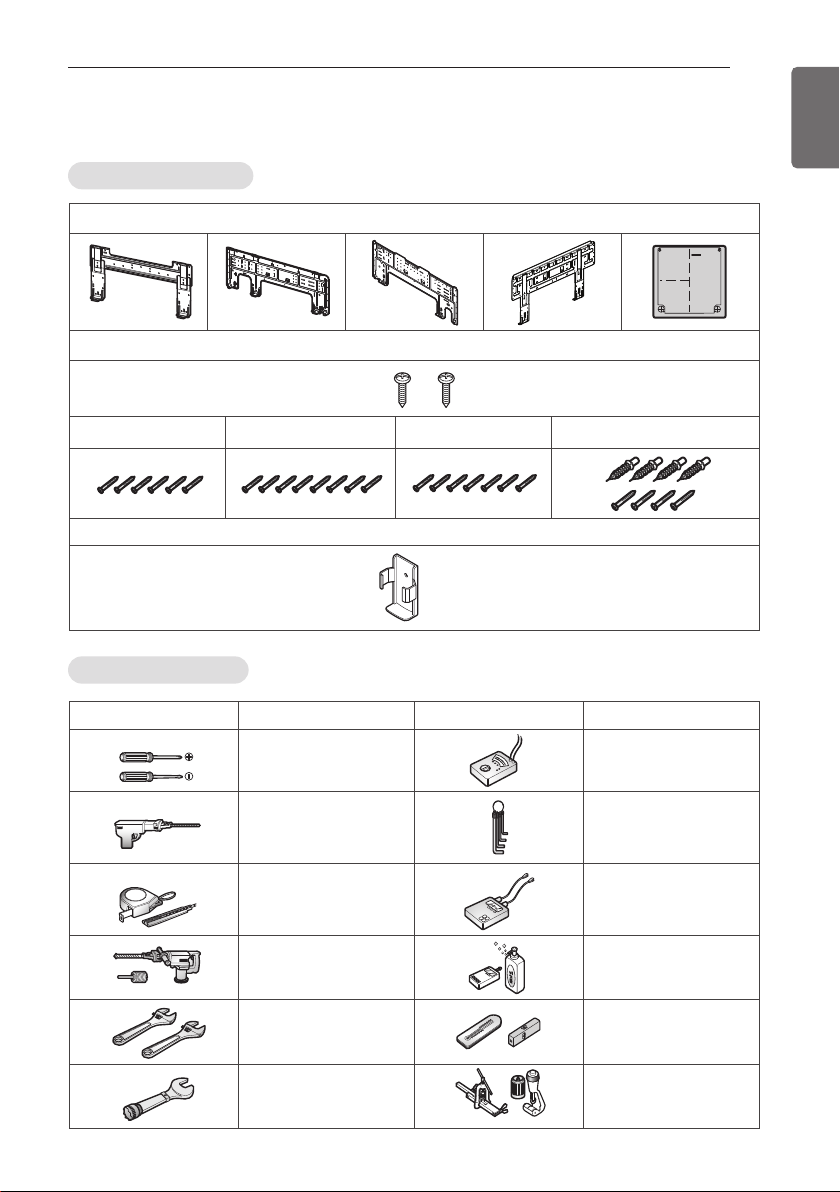
Installation plate
Type "B" screws
Type "A" screw (6 EA) Type "A" screw (8 EA) Type "A" screw (7 EA)
Holder Remote Control
Type "A" screw and plastic anchors
Figure FigureName
Screw driver
Electric drill
Measuring tape, Knife
Hole core drill
Spanner
Torque wrench
Multi-meter
Hexagonal wrench
Ammeter
Gas-leak detector
Thermometer,
Level
Flaring tool set
Name
INSTALLATION
Installation Parts
INSTALLATION
7
ENGLISH
Installation Tools
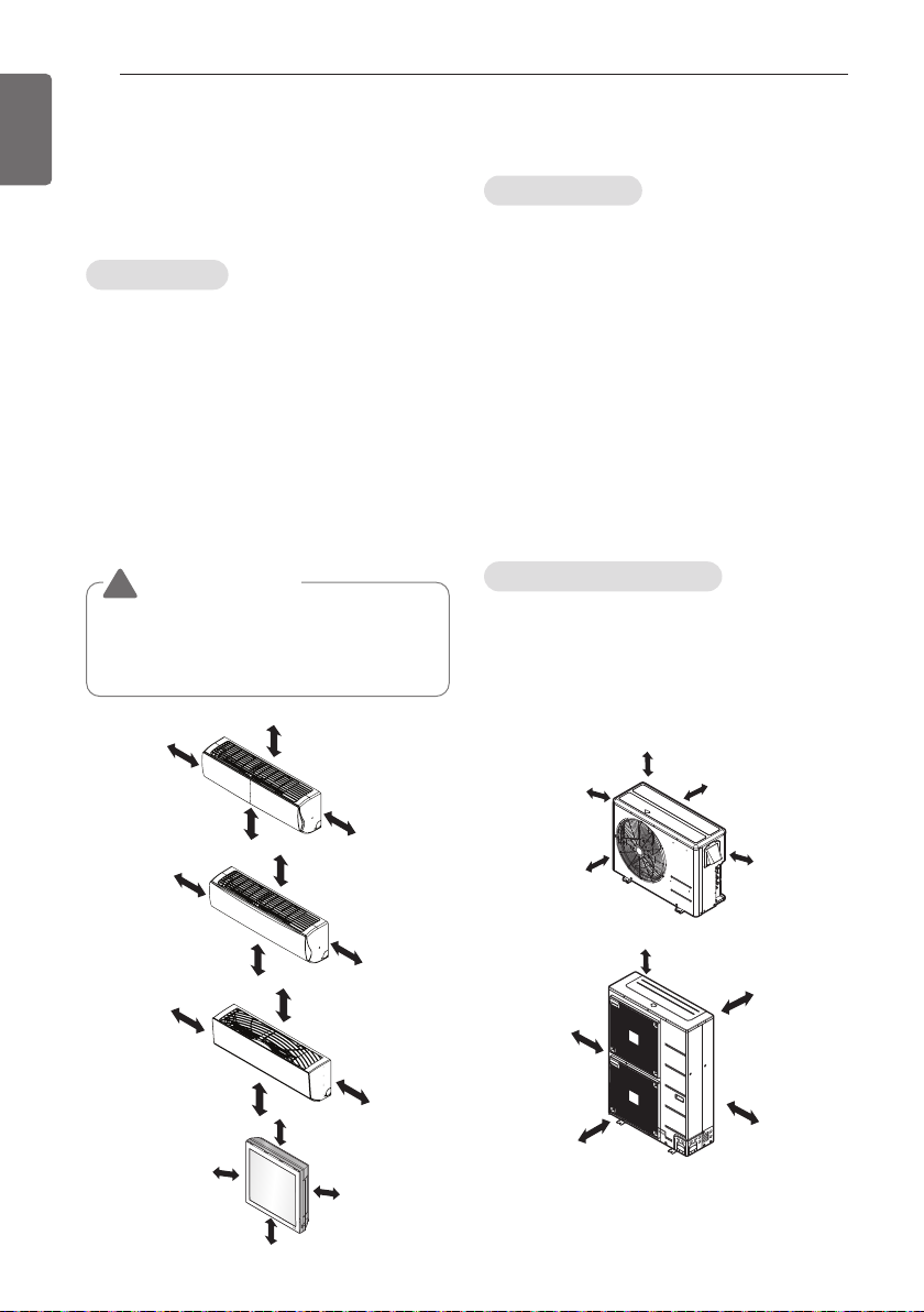
INSTALLATION OF INDOOR, OUTDOOR UNIT
More than 20 cm
More than
10 cm
More than 2.3 m
More than
10 cm
More than 20 cm
More than
10 cm
More than 2.3 m
More than
10 cm
More than 20 cm
More
than 50 cm
More than 1.5 m
More
than 50 cm
More than 20 cm
More than
10 cm
More than 2.3 m
More than
10 cm
more than
70 cm
more than
30 cm
more than
30 cm
more than
60 cm
more than 60 cm
more than
70 cm
more than
30 cm
more than 60 cm
more than
30 cm
more than
60 cm
8
ENGLISH
INSTALLATION OF INDOOR, OUTDOOR UNIT
Read completely, then follow step by step.
Select the best location
Indoor unit
1 Do not have any heat or steam near the
unit.
2 Select a place where there are no obstacles
in front of the unit.
3 Make sure that condensation drainage can
be conveniently routed away.
4 Do not install near a doorway.
5
Ensure the spaces indicated by arrows from
the wall, ceiling, fence or other obstacles.
6 Use a stud finder to locate studs to prevent
unnecessary damage to the wall.
CAUTION
!
Install the indoor unit on the wall where
the height from the floors more than 2.3
meters. (ART COOL Type Only 1.5 m)
Outdoor unit
1 If an awning is built over the unit to prevent
direct sunlight or rain exposure, make sure
that heat radiation from the condenser is
not restricted.
2 Ensure that the spaces indicated by arrows
around front, back and side of the unit.
3 Do not place animals and plants in the path
of the warm air.
4 Take the air conditioner weight into account
and select a place where noise and
vibration are minimum.
5 Select a place so that the warm air and
noise from the air conditioner do not
disturb neighbors.
Rooftop Installations
If the outdoor unit is installed on a roof
structure, be sure to level the unit. Ensure the
roof structure and anchoring method are
adequate for the unit location. Consult local
codes regarding rooftop mounting.
INSTALLATION OF INDOOR, OUTDOOR UNIT
Foundation for Installation
• Check the strength and level of the installation ground so that the unit will not cause any
operating vibration or noise after installation.
• Fix the unit securely by means of the foundation bolts. (Prepare 4 sets of M12 foundation bolts,
nuts and washers each which are available on the market.)
• It is best to screw in the foundation bolts until their length are 20 mm from the foundation
surface.
9
ENGLISH
Frame
H-Beam
100
Spring washer
Concrete
Nut
75
Foundation bolt executing method
base
200
Anti-vibration
materials
Four bolt are
required
3 thread ridges
75
200
[Unit:mm]
INSTALLATION OF INDOOR, OUTDOOR UNIT
10
ENGLISH
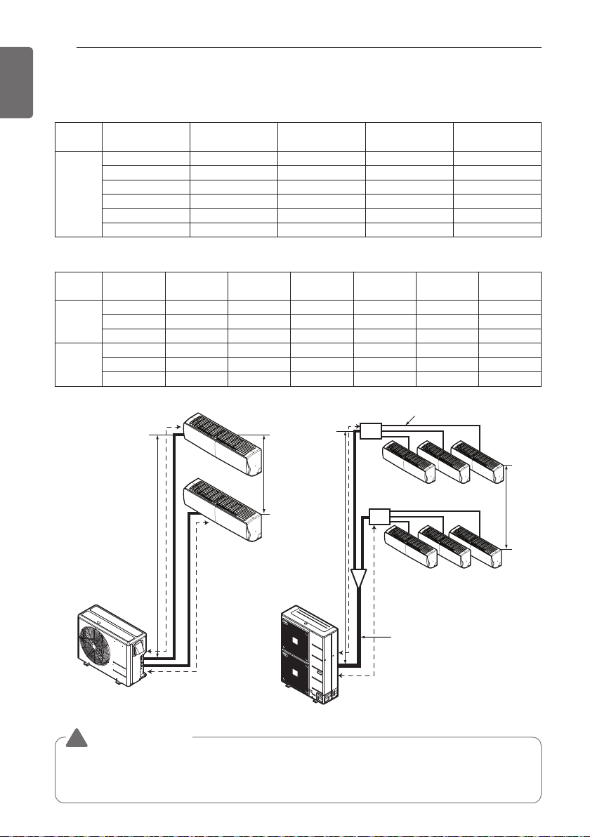
Piping length and elevation
Multiple Piping Models (Unit: m)
Phase Capacity(kBtu/h) Total Length Max Length(A/B)
14/16 30 20 15 7.5
18 50 25 15 7.5
1Ø
21 50 25 15 7.5
24/27 70 25 15 7.5
30 75 25 15 7.5
40/48 85 25 15 7.5
Distributor type Models (Unit: m)
Phase
Capacity
(kBtu/h)
Total
Length
Max Main Pipe
Length (A/B)
Total Branch
Pipe Length
40 100 50 50 15 30 15
1Ø
48 135 55 80 15 30 15
56 145 55 90 15 30 15
42 125 55 70 15 30 15
3Ø
48 135 55 80 15 30 15
56 145 55 90 15 30 15
Max Elevation
(h1)
Max Branch
Pipe Length
Max Elevation
(h1)
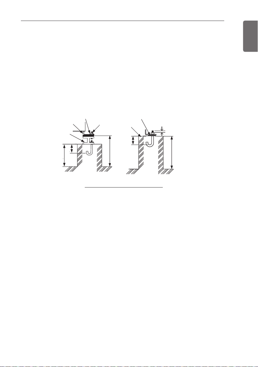
In - In Elevation
(h2)
In - In
Elevation (h2)
Branch Pipe
Main Pipe
Multiple Piping Type Distributor Type
CAUTION
!
h1
Distributor
A
Distributor
B
A
h2
h1
B
Capacity is based on standard length and maximum allowance length is on the basis of
reliability. If outdoor unit is at higher elevation than the indoor units, after 24 m of vertical
height, 1 oil trap is required.
h2
INSTALLATION OF INDOOR, OUTDOOR UNIT
Refrigerant charge
The calculation of the additional charge should be taken in account for the length of extra pipe.
Multiple Piping Models (Unit: m)
Phase Capacity(kBtu/h)
Standard
Length(m)
14/16 7.5 20 30 20
18 7.5 25 50 20
1Ø
21 7.5 25 50 20
24/27 7.5 25 70 20
30 7.5 25 75 20
40/48 7.5 25 85 20
Distributor type Models (Unit: m)
Main Piping length Branch piping length
Phase Capacity(kBtu/h)
Standard
length(m)
40 5 50 5 20
1Ø
48 5 50 5 20
56 5 50 5 20
42 5 50 5 20
3Ø
48 5 50 5 20
56 5 50 5 20
• Multiple Piping Models
Additional charge (g) = ((A Room Installation Length – Standard Length ) x 20 g/m
+ (B Room Installation Length – Standard Length ) x 20 g/m +.. )
- CF(Correction Factor) x 150
h CF = Max. number of connectable indoor unit – Total number of connected indoor unit
• Distributor type Models
Additional charge (g) = (( Total Main piping Length - Main Standard Length ) x 50 g/m
+ (A Room Branch Length – Standard Length ) x 20 g/m
+ (B Room Branch Length – Standard Length ) x 20 g/m
+ (C Room Branch Length – Standard Length ) x 20 g/m +.. )
- CF(Correction Factor) x 100
h CF = Max. number of connectable indoor unit – Total number of connected indoor unit
Max Piping for
one room(m)
Additional
refrigerant(g/m)
Max total Piping
Length
Standard
length(m)
Additional
Charge(g/m)
Additional
refrigerant(g/m)
11
ENGLISH
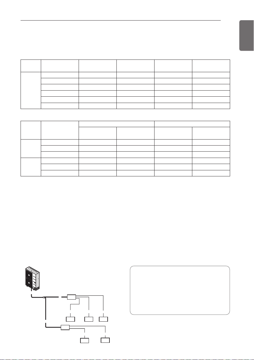
• Total main pipe(A+B+C) = 30 m
Ex) Distributor type Model 1Ø, 40 kBtu/h
A
A
C
• Each branch pipe
a = 10 m
b = 8 m
c = 5 m
d = 3 m
abc
B
7k 9k 9k
e = 10 m
*Additional Charge
=((30-5) x 50 + (10-5) x 20 + (8-5) x 20
18k
e
+ (5-5) x 20 + (3-5) x 20 + (10-5) x 20)
- (7-5) x 100 = 1 270 g
d
9k
FLARING WORK AND CONNECTION OF PIPING
Copper
tube
90°
Slanted Uneven Rough
Pipe
Reamer
Point down
Flare nut
Copper tube
12
ENGLISH
FLARING WORK AND CONNECTION OF
PIPING
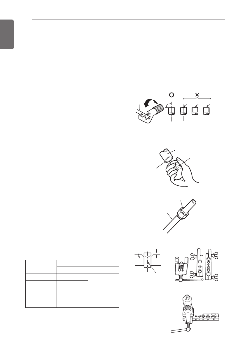
Flaring work
Main cause for gas leakage is due to defect in flaring work. Carry out correct flaring work in the
following procedure.
Cut the pipes and the cable
- Use the piping kit accessory or the pipes
purchased locally.
- Measure the distance between the indoor
and the outdoor unit.
- Cut the pipes a little longer than measured
distance.
- Cut the cable 1.5 m longer than the pipe
length.
Burrs removal
- Completely remove all burrs from the cut
cross section of pipe/tube.
- Put the end of the copper tube/pipe in a
downward direction as you remove burrs in
order to avoid dropping burrs into the tubing.
Putting nut on
- Remove flare nuts attached to indoor and
outdoor unit, then put them on pipe/tube
having completed burr removal.
(not possible to put them on after flaring
work)
Flaring work
- Carry out flaring work using flaring tool as
shown below.
Pipe diameter
Inch (mm)
Ø 1/4 (Ø 6.35) 0.04~0.05(1.1~1.3)
Ø 3/8 (Ø 9.52) 0.06~0.07(1.5~1.7)
Ø 1/2 (Ø 12.7) 0.06~0.07(1.6~1.8)
Ø 5/8 (Ø 15.88) 0.06~0.07(1.6~1.8)
Ø 3/4 (Ø 19.05) 0.07~0.08(1.9~2.1)
Firmly hold copper pipe in a bar in the
dimension shown in the table below.
Wing nut type Clutch type
A inch (mm)
0~0.02
(0~0.5)
Bar
<Wing nut type>
"A"
Copper pipe
<Clutch type>
 Loading...