

LG A5UW306FA3, A5UW406FA3, A8UW486FA3, A9UW566FA3, A7UW428FA3 Installation Manual
...
www.lg.com
INSTALLATION MANUAL
AIR CONDITIONER
• Please read this installation manual completely before installing the product.
• Installation work must be performed in accordance with the national wiring
standards by authorized personnel only.
• Please retain this installation manual for future reference after reading it
thoroughly.
TYPE : MULTI
P/NO : 3828A20567H
ENGLISH
ITALIANO
ESPAÑOL FRANÇAIS
DEUTSCH

2 Multi Air Conditioner
Multi Type Air Conditioner Installation Manual
CONTENTS
Installation Parts Provided.........................................3
Safety Precautions..................................................4~5
Installation of indoor, outdoor unit .....................6~11
Flaring work and connection of piping.............12~21
Connecting the Cable between Indoor Unit and
Outdoor Unit........................................................22~24
Checking the Drainage, Forming the Pipings
and Long pipe Setting ........................................25~27
Air Purging and Evacuation.....................................28
Panel Front Assembly ..............................................30
Installation PI485.......................................................31
Test running...............................................................33
Combination indoor units ........................................34
Max Combination Capacity ......................................35
Installation guide at the seaside..............................36
Seasonal wind and cautions in winter....................36
❏ Level gauge
❏ Screw driver
❏ Electric drill
❏ Hole core drill (ø65mm)
❏ Horizontal meter
❏ Flaring tool set
❏ Specified torque wrenches
1.8kg.m, 4.2kg.m, 5.5kg.m, 6.6kg.m
(different depending on model No.)
❏ Spanner .................Half union
❏ A glass of water
❏ Screw driver
❏ Hexagonal wrench(4mm)
❏ Gas-leak detector
❏ Vacuum pump
❏ Gauge manifold
❏ Owner's manual
❏ Thermometer
❏ Holder Remote Control
Installation Requirements
Required Tools
Installation Parts Provided
Installation Manual 3
ENGLISH
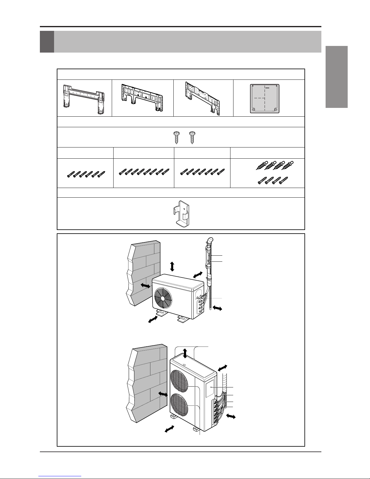
Installation Parts Provided
Installation plate
Type "B" screws
Type "A" screw (6 EA) Type "A" screw (8 EA) Type "A" screw (7 EA)
Holder Remote Control
Type "A" screw and plastic anchors
Standard Type
5. Copper pipe (Liquid side)
6. Copper pipe (Gas side)
7. Connecting cable
more than
30cm
more than
60cm
more than
60cm
more than
70cm
more than
30cm
more than
30cm
more than
70cm
more than
30cm
more than
30cm
Air Outlet
Air Intake
(side, rear)
Connection pipe
Drain hose
Connecting wire
Control cover
more than
30cm
more than
60cm
more than
60cm
4 Multi Air Conditioner
Do not disassemble or repair the product.
• Contact your dealer or service center.
Always earth the product.
• It will cause fire or electric shock.
Do not handle the flamable gas or explosive
materials near the product.
• Otherwise, it may cause fire or failure of
product.
Do not install where flamable gas could
leak.
• Otherwise, it may cause esplosion or fire.
Do not install the product on a defected
installation stand.
• Otherwise, It may cause injury or accident.
Be cautious when unpacking and installing
the product.
• Sharp edges could cause injury.
Do not use damaged power cable.
• It will cause fire or electric shock.
Always intstall a circuit breaker and main
breaker.
• No installation may cause fire and electric
shock.
For installation, always contact the dealer or
service center.
• Otherwise, it may cause fire, electric shock,
explosion or injury."
For electric work, contact the dealer or
service center.
• Otherwise, It will cause fire or electric shock.
Safety Precautions
To prevent injury to the user or other people and property damage, the following instructions
must be followed.
■ Incorrect operation due to ignoring instruction will cause harm or damage. The seriousness
is classified by the following indications.
■ Meanings of symbols used in this manual are as shown below.
WARNING
CAUTION
This symbol indicates the possibility of death or serious injury.
This symbol indicates the possibility of injury or damage.
WARNING
Be sure not to do.
Be sure to follow the instruction.
Safety Precautions
Installation Manual 5
ENGLISH
Safety Precautions
Do not put the heater, etc. near the power
cable.
• Otherwise, it may cause fire and electric shock.
Cover the electric part.
• Otherwise, it may cause fire or electric shock.
Do not turn the breaker on/off during
operation.
• Otherwise, it may cause fire or electric shock.
Do not open the suction inlet of the product
during operation.
• Otherwise, it may cause electric shock or
failure.
Do not touch the metal parts of the product
when removing the air filter.
• Otherwise, it may cause personal injury.
Do not step or put anyting on the product.
• Otherwise, it may cause personal injury and
failure of product.
Always inspect gas leakage after
installation and repair of product.
• Otherwise, it may cause failure of product.
Install the drain hose to ensure that drain
can be securely done.
• Otherwise, it may cause water leakage.
Keep the level even while installing the
product.
• Otherwise, it may cause vibration or water
leakage.
Do not install the product where the noise
or hot wind from the outdoor unit could
give any casualty to the neighborhood
• Otherwise, it may cause dispute with the
neighborhoods.
Do not touch(operate) product with wet
hands.
• Otherwise, it may cause fire or electric shock.
If strange sound, smell or smoke come from
product, turn the breaker off.
• Otherwise, it may cause electric shock or fire.
CAUTION
Fix the outdoor unit on the floor.
• Otherwise, it can be blown away by the strong
wind. It will cause injury or accident.
Use a vacuum pump or Inert (nitrogen) gas when
doing leakage test or air purge. Do not compress
air or Oxygen and Do not use Flammable gases.
Otherwise, it may cause fire or explosion.
•
There is the risk of death, injury, fire or
explosion.
6 Multi Air Conditioner
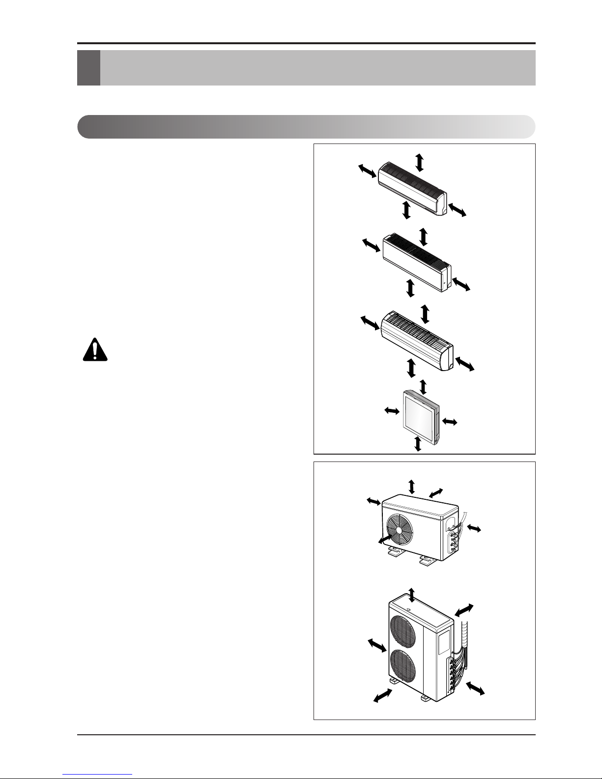
Installation of Indoor, Outdoor Unit
Installation of Indoor, Outdoor Unit
Read completely, then follow step by step.
Indoor unit
1. Do not have any heat or steam near the unit.
2. Select a place where there are no obstacles
in front of the unit.
3. Make sure that condensation drainage can be
conveniently routed away.
4. Do not install near a doorway.
5. Ensure the spaces indicated by arrows from
the wall, ceiling, fence or other obstacles.
6. Use a stud finder to locate studs to prevent
unnecessary damage to the wall.
Outdoor unit
1. If an awning is built over the unit to prevent
direct sunlight or rain exposure, make sure
that heat radiation from the condenser is not
restricted.
2. Ensure that the spaces indicated by arrows
around front, back and side of the unit.
3. Do not place animals and plants in the path
of the warm air.
4. Take the air conditioner weight into account
and select a place where noise and vibration
are minimum.
5. Select a place so that the warm air and noise
from the air conditioner do not disturb
neighbors.
Rooftop Installations:
If the outdoor unit is installed on a roof
structure, be sure to level the unit. Ensure the
roof structure and anchoring method are
adequate for the unit location. Consult local
codes regarding rooftop mounting.
Select the best location
More than 20cm
More than
10cm
More than 2.3m
More than
10cm
More than 20cm
More than
10cm
More than 2.3m
More than
10cm
More than 20cm
More
than 50cm
More than 1.5m
More
than 50cm
More than 20cm
More than
10cm
More than 2.3m
More than
10cm
more than
70cm
more than
30cm
more than
30cm
more than
30cm
more than
30cm
more than 60cm
more than
60cm
more than
60cm
more than
70cm
more than 60cm
CAUTION: Install the indoor unit
on the wall where the height from
the floors more than 2.3 meters.
(ART COOL Type Only 1.5m)
Installation of Indoor, Outdoor Unit
Installation Manual 7
ENGLISH
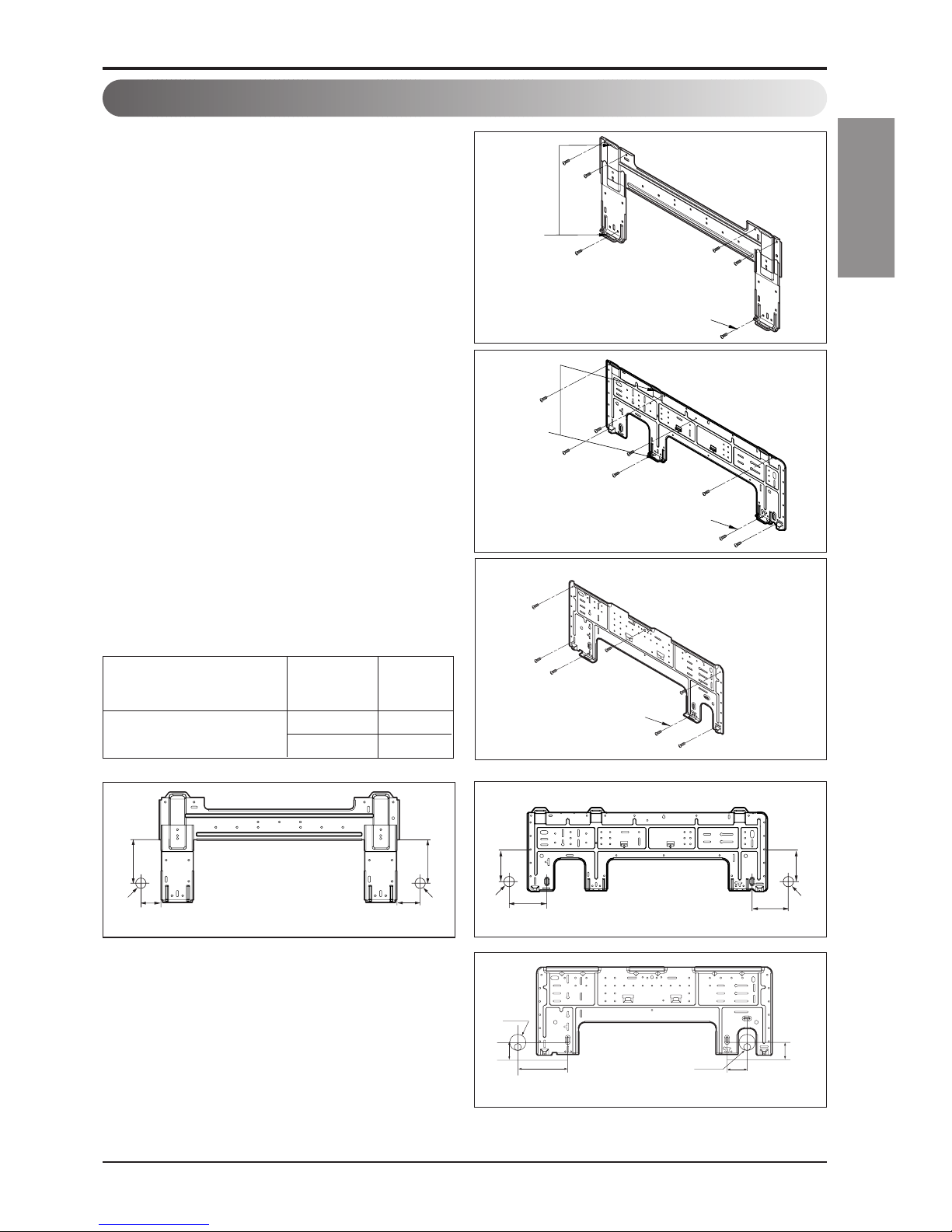
The wall you select should be strong and solid
enough to prevent vibration
1. Mount the installation plate on the wall with
type "A" screws. If mounting the unit on a
concrete wall, use anchor bolts.
• Mount the installation plate horizontally by
aligning the centerline using a level.
2. Measure the wall and mark the centerline. It
is also important to use caution concerning
the location of the installation plate-routing
of the wiring to power outlets is through the
walls typically. Drilling the hole through the
wall for piping connections must be done
safely.
Chassis
Hook
Installation Plate
Type “A”
Installation plate
Left rear piping Right rear piping
Ø70mm
Ø70mm
105mm
105mm
55mm
65mm
<Type 1>
<Type 1>
45mm
140mm
Ø 70mm
65mm
45mm
Ø 70mm
Installation plate
Left rear piping
Right rear piping
<Type 3>
Installation plate
Left rear piping Right rear piping
Ø70mm
133mm
101mm 101mm
Ø70mm
100mm
<Type 2>
Chassis
Hook
Installation Plate
Type “A”
<Type 2>
Fixing Installation Plate
Wall mounted 7,9,12 1/3
/ART COOL Mirror 18, 24 2
Indoor Type
Capacity
(kBtu/h)
Type
Installation Plate
Type “A”
<Type 3>
Installation of Indoor, Outdoor Unit
8 Multi Air Conditioner
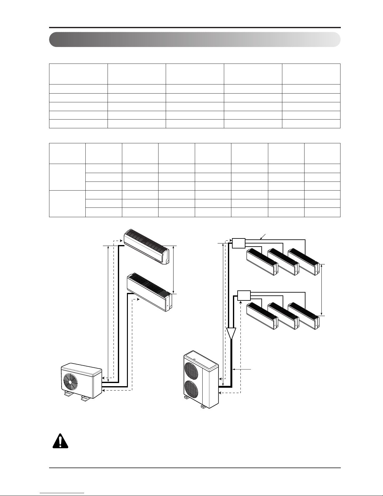
h2
h1
h1
A
A
Branch Pipe
Main Pipe
Distributor
Distributor
B
B
h2
Multi Piping Type Distributor Type
Multi Piping Type (Unit: m)
Distributor Type (Unit: m)
Piping length and elevation
18 40 25 15 7.5
21 50 25 15 7.5
24/27 70 25 15 7.5
30 75 25 15 7.5
40 85 25 15 7.5
Capacity(kBtu/h) Total Length Max Length(A/B)
Max Elevation
(h1)
In - In Elevation
(h2)
40 100 50 50 15 30 15
1Ø 48 135 55 80 15 30 15
56 145 55 90 15 30 15
42 125 55 70 15 30 15
3Ø 48 135 55 80 15 30 15
54 145 55 90 15 30 15
Phase
Capacity
(kBtu/h)
Total Length
Max Main Pipe
Length (A/B)
Total Branch
Pipe Length
Max Branch
Pipe Length
Max Elevation
(h1)
In - In Elevation
(h2)
CAUTION: Capacity is based on standard length and maximum allowance
length is on the basis of reliability. If outdoor unit is at higher elevation than
the indoor units, after 24m of vertical height, 1 oil trap is required.
Installation of Indoor, Outdoor Unit
Installation Manual 9
ENGLISH
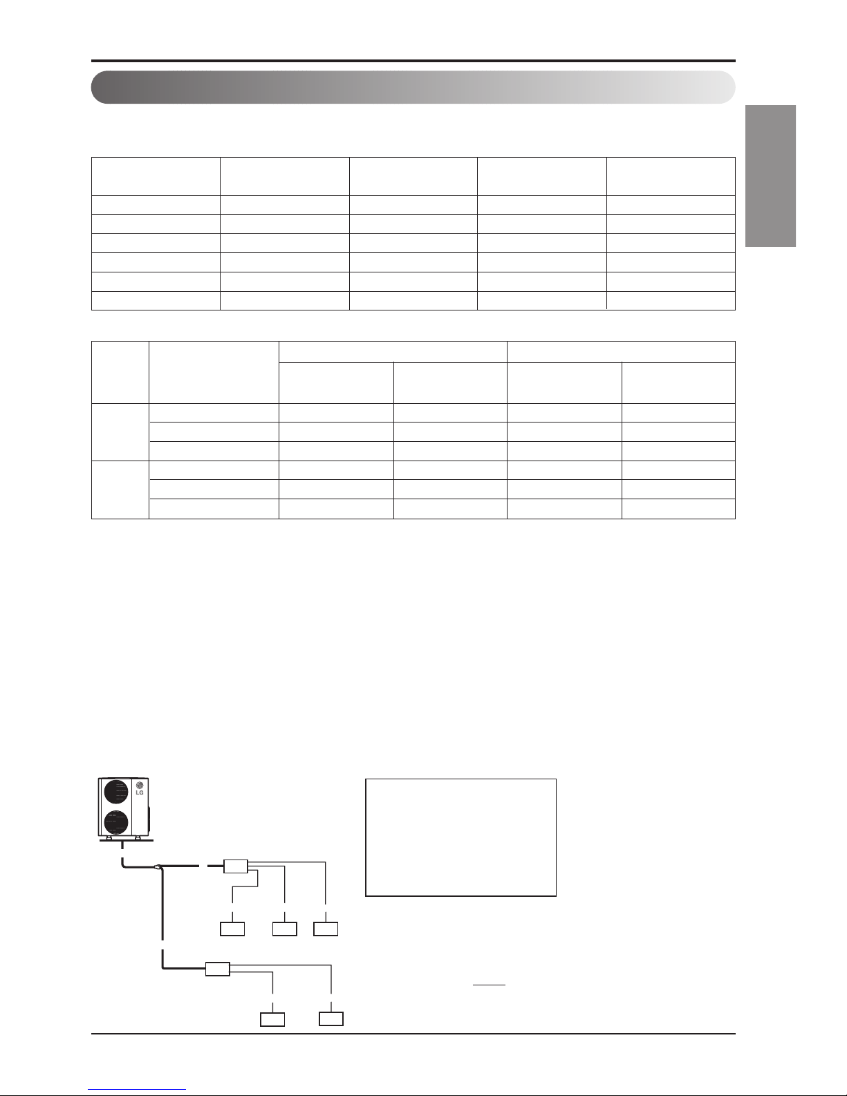
Refrigerant charge
The calculation of the additional charge should be taken in account for the length of extra pipe.
• Total main pipe(A+B+C) = 30m
• Each branch pipe
a = 10m
b = 8m
c = 5m
d = 3m
e = 10m
❖
Additional Charge
=((30-5) x 50 + (10-5) x 20 + (8-5) x 20
+ (5-5) x 20 + (3-5) x 20 + (10-5) x 20)
- (7-5) x 100 = 1270g
A
Ex) A7UW406FA3
A
B
C
abc
7k 9k 9k
d
e
9k
18k
■ Multiple Piping Models
■ Distributor type Models
Additional charge (g) = ((A Room Installation Length – Standard Length ) x 20g/m
+ (B Room Installation Length – Standard Length ) x 20g/m +.. )
- CF(Correction Factor) x 150
❈ CF = Max. number of connectable indoor unit – Total number of connected indoor unit
Additional charge (g) = (( Total Main piping Length - Main Standard Length ) x 50g/m
+ (A Room Branch Length – Standard Length ) x 20g/m
+ (B Room Branch Length – Standard Length ) x 20g/m
+ (C Room Branch Length – Standard Length ) x 20g/m +.. )
- CF(Correction Factor) x 100
❈ CF = Max. number of connectable indoor unit – Total number of connected indoor unit
Additional Charge Calculation Example-1
Model
Standard
length(m)
Max piping for
one room(m)
Max total Piping
Length(m)
Additional
Charge(g/m)
A3UW186FA3[FM19AH]
7.5 25 40 20
A3UW216FA3/4[FM21AH]
7.5 25 50 20
A4UW246FA3/4[FM25AH]
7.5 25 70 20
A4UW276FA3[FM27AH]
7.5 25 70 20
A5UW306FA3[FM30AH]
7.5 25 75 20
A5UW406FA3[FM38AH]
7.5 25 85 20
Multiple Piping Models
ModelPhase
Main Piping length Branch piping length
Standard
length(m)
Additional
refrigerant(g/m)
Standard
length(m)
Additional
refrigerant(g/m)
A7UW406FA2/3[FM40AH]
550520
1Ø
A8UW486FA3[FM48AH]
550520
A9UW566FA3[FM56AH]
550520
A7UW428FA3[FM41AH]
550520
3Ø
A8UW488FA3[FM49AH]
550520
A9UW548FA3[FM57AH]
550520
Distributor type Models
10 Multi Air Conditioner
Installation of Indoor, Outdoor Unit
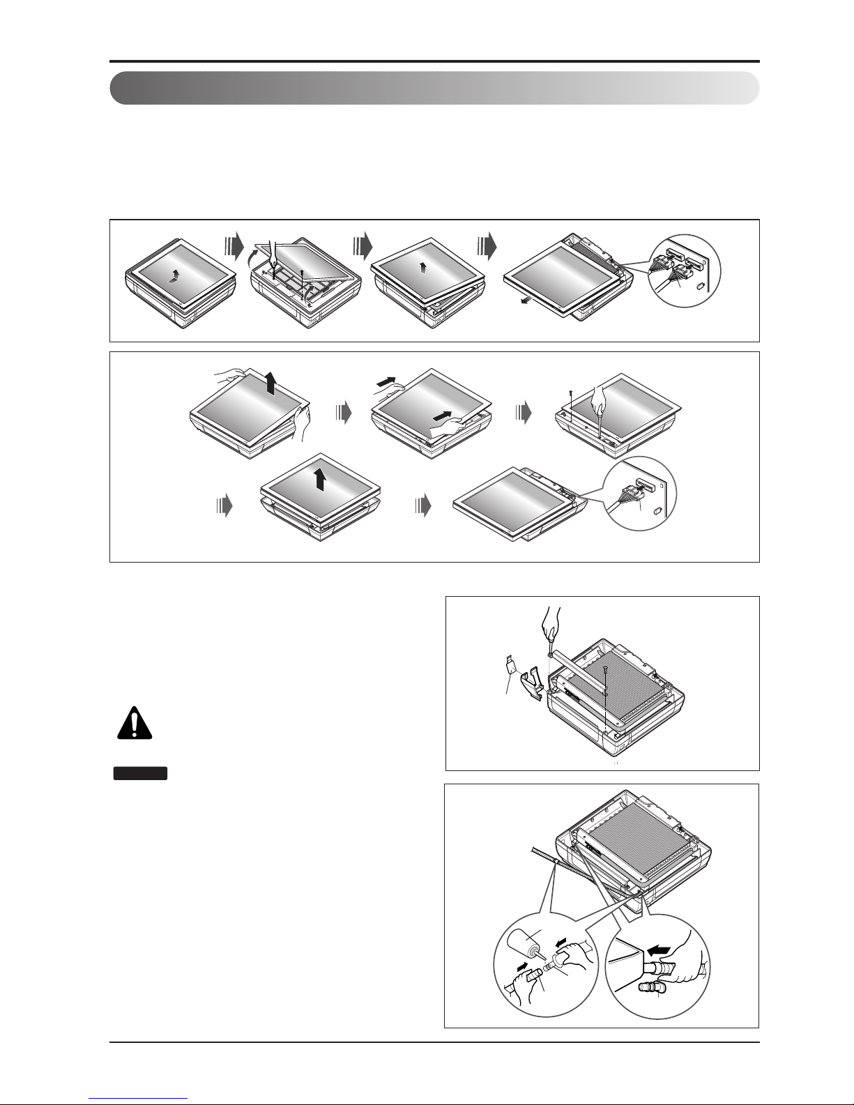
Preparing work for Installation (ART COOL Type Only)
Open panel front
1. First, push the front panel backward and lift it up to remove the two screws.
2. The moment of lifting the both lower parts of panel front, you can hear sound this panel came
out, In this time panel front is separated
3. After pull down this panel a bit, and separate connecting wire with product.
Remove cover pipe and cover side
1. Remove two screws(for fixing cover pipe)
2. Pull up the cover side of desired connecting
direction, then cover side is separated.
3. In case of connecting direction is left or right,
path through the hole of cover side.
CAUTION: After removing the pipe
hole, cut the burr for safety.
When connecting pipe path through rear
wall, don’t remove the hole.
NOTICE
Drain hose junction
1. Remove the rubber stopple of desired
direction of drainage.
2. As the following picture, Insert drain hose in
the handle of drain pan, and join drain hose
and connecting hose.
Panel Front
Connector
Panel Front
Connector
Pipe hole
rubber cap
Only one
desiring direction
Connecting
part
Adhesive
Drain
hose
Installation Manual 11
ENGLISH
Installation of Indoor, Outdoor Unit
• Drill the piping hole with a Ø65mm hole
core drill. Drill the piping hole at either the
right or the left with the hole slightly slanted
to the outdoor side.
Drill a hole in the wall
5-7mm
(3/16"~5/16")
Indoor
WALL
Outdoor
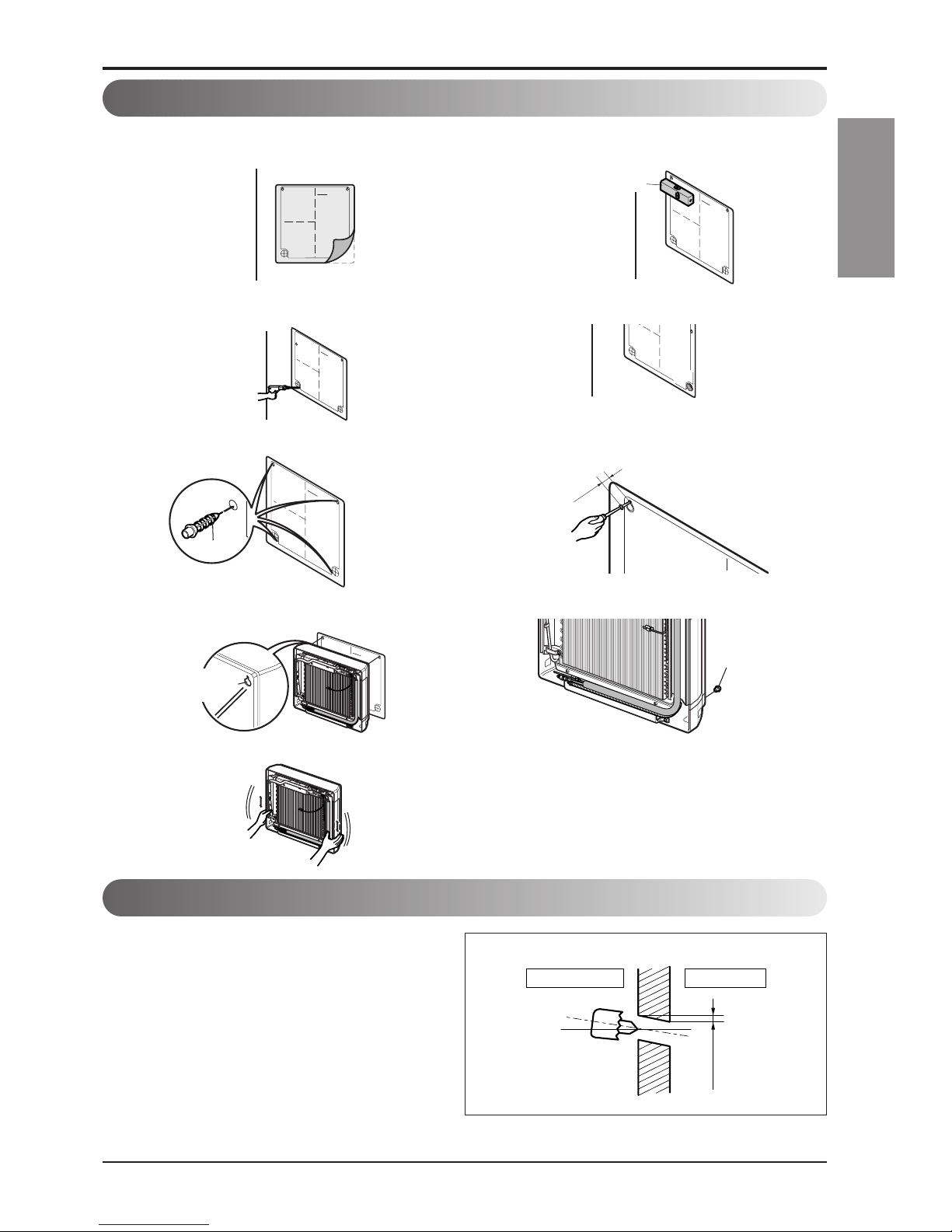
Sticking the installation guide map and fixing Indoor unit (ART COOL Type Only)
Plastic anchors
INSTALLATION GUIDE MAP
10mm
INSTALLATION GU
INSTAIIATIO
N G
UID
E M
AP
Put an Installation Guide Map on the desired surface.
Make a hole with diameter of 6mm and depth of
30-35mm when piercing a screw point.
Drive the four plastic anchors into drilled points.
Hang the hole of product at the upper screws.
(In this time, Remove the map)
(Falling attention)
Check the fixed product with light power.
Adjust level even by level guage and fix to installation
for reference on the wall.
Drill the piercing part for connecting pipe as diameter
Ø65mm. (In case of piercing rear surface)
Refer to No. 5 on this page when making a hole in the wall.
First, Drive the two points of the upper parts by screws
(Leave 10mm for hanging product)
Drive the lower parts after facing the hole of product
with plastic anchors, and fix completely the upper
screws.
In case of nothing wrong in the matter, connect the pipe
and the wire. (Installation manual reference)
Horizontality
INSTALLATION GUIDE MAP
Plastic anchors
INSTALLATION GUIDE MAP
INSTA
LLATIO
N G
UIDE M
A
P
Hanger hole
(Rear side of
product)
12 Multi Air Conditioner
Flaring Work and Connection of Piping
Flaring work
Main cause for gas leakage is due to defect in flaring work. Carry out correct flaring work in the
following procedure.
Cut the pipes and the cable.
1. Use the piping kit accessory or the pipes
purchased locally.
2. Measure the distance between the indoor and
the outdoor unit.
3. Cut the pipes a little longer than measured
distance.
4. Cut the cable 1.5m longer than the pipe length.
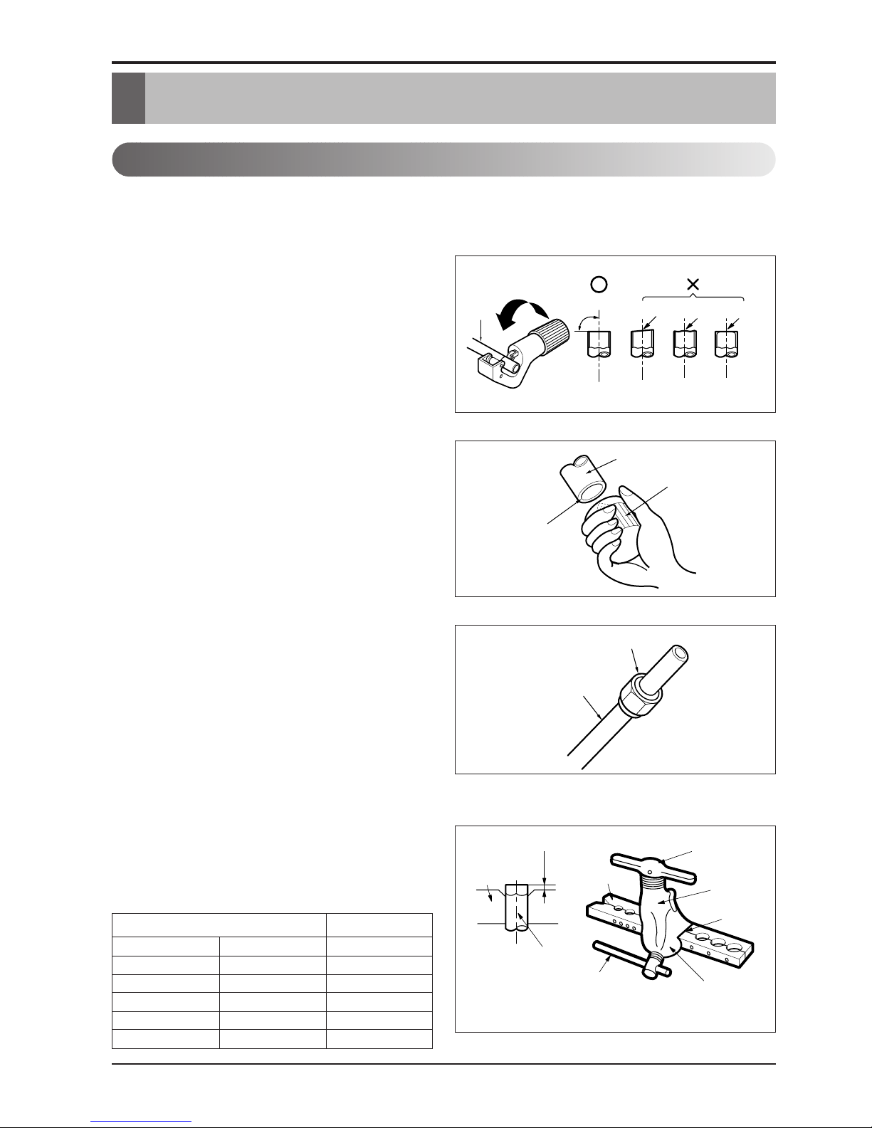
Burrs removal
1. Completely remove all burrs from the cut cross
section of pipe/tube.
2. Put the end of the copper tube/pipe in a
downward direction as you remove burrs in
order to avoid dropping burrs into the tubing.
Putting nut on
• Remove flare nuts attached to indoor and
outdoor unit, then put them on pipe/tube having
completed burr removal.
(not possible to put them on after flaring work)
Flaring work
• Carry out flaring work using flaring tool as shown
below.
• Firmly hold copper pipe in a bar in the dimension
shown in the table below.
Copper
pipe
90°
Slanted Uneven Rough
Pipe
Reamer
Point down
Flare nut
Copper tube
mm inch mm
Ø6.35 1/4 1.1~1.3
Ø9.52 3/8 1.5~1.7
Ø12.7 1/2 1.6~1.8
Ø15.88 5/8 1.6~1.8
Ø19.05 3/4 1.9~2.1
Outside diameter A
Bar
Copper pipe
Clamp handle
Red arrow mark
Cone
Yoke
Handle
Bar
"A"
Flaring Work and Connection of Piping
 Loading...