

LG A4UW306FA0 INSTALLATION MANUAL

LG
Air Conditioner
INSTALLATION MANUAL
LG
website http://www.lgservice.com
e-mail http://www.lgeservice.com/techsup.html
IMPORTANT
• Please read this installation manual completely before
installing the product.
• When the power cord is damaged, replacement work shall
be performed by authorized personnel only.
• Installation work must be performed in accordance with
the national wiring standards by authorized personnel
only.

2 Room Air Conditioner
Multi Type Air Conditioner Installation Manual
TABLE OF CONTENTS
The following should be
always observed for safety ....................................3~5
Installation of indoor, outdoor unit .....................7~11
Flaring work and connection of piping.............12~15
Connecting the Cable between Indoor Unit and
Outdoor Unit ........................................................16~17
Checking the Drainage, Forming the Pipings
and Long pipe Setting ........................................18~19
Air Purging...........................................................20~21
Panel Front Assembly ..............................................22
Test running...............................................................23
Combination indoor units ........................................24
Combination table of Models...................................25
❏ Level gauge
❏ Screw driver
❏ Electric drill
❏ Hole core drill (ø50mm)
❏ Horizontal meter
❏ Flaring tool set
❏ Specified torque wrenches
1.8kg.m, 4.2kg.m, 5.5kg.m, 6.6kg.m
(different depending on model No.)
❏ Spanner .................Half union
❏ A glass of water
❏ Screw driver
❏ Hexagonal wrench(4mm)
❏ Gas-leak detector
❏ Vacuum pump
❏ Gauge manifold
❏ Owner's manual
❏ Thermometer
❏ Holder Remote Control
Installation Requirements
Required Tools

Installation Parts Provided
Installation Manual 3
Installation Parts Provided
Type "A" screws and plastic anchors
Type "B" screws
Holder Remote Control
Installation plate
Standard Type
5. Copper pipe (Liquid side)
6. Copper pipe (Gas side)
7. Connecting cable
more than
20cm
more than
70cm
more than
20cm
more than
20cm
more than
70cm
more than
30cm
more than
30cm
Air Outlet
Air Intake
(side, rear)
Connection pipe
Drain hose
Connecting wire
Control cover
more than
30cm
4 Room Air Conditioner
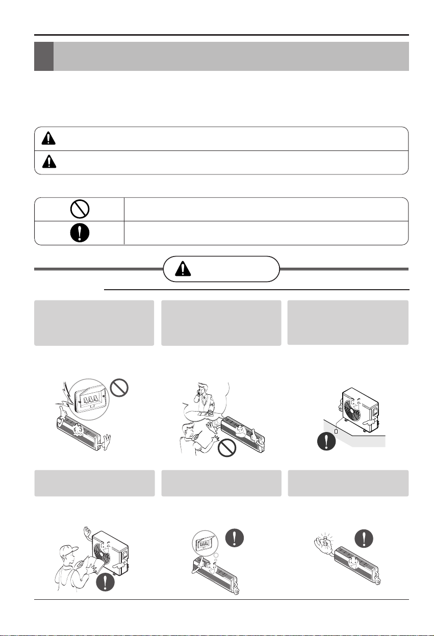
Safety Precautions
To prevent injury to the user or other people and property damage, the following instructions
must be followed.
■
Incorrect operation due to ignoring instruction will cause harm or damage. The seriousness
is classified by the following indications.
■ Meanings of symbols used in this manual are as shown below.
This symbol indicates the possibility of death or serious injury.
This symbol indicates the possibility of injury or damage.
WARNING
Be sure not to do.
Be sure to follow the instruction.
Safety Precautions
■ Installation
Install the panel and the cover of
control box securely.
• There is risk of fire or
electric shock.
Always install a dedicated
circuit and breaker.
• Improper wiring or
installation may cause fire or
electric shock
Use the correctly rated breaker
or fuse.
• There is risk of fire or
electric shock.
Do not use a defective or
underrated circuit breaker. Use
this appliance on a dedicated
circuit.
• There is risk of fire or
electric shock.
For electrical work, contact the
dealer, seller, a qualified
electrician, or an Authorized
Service Center.
•
Do not disassemble or repair
the product. There is risk of
fire or electric shock.
Always ground the product.
• There is risk of fire or
electric shock.
WARNING
CAUTION
Installation Manual 5
Safety Precautions
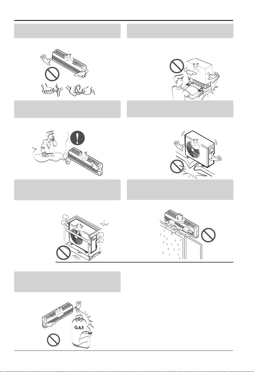
Do not modify or extend the power cable.
• There is risk of fire or electric shock.
Be cautious when unpacking and installing the
product.
•
Sharp edges could cause injury. Be especially
careful of the case edges and the fins on the
condenser and evaporator.
For installation, always contact the dealer or an
Authorized Service Center.
• There is risk of fire, electric shock, explosion,
or injury.
Do not install the product on a defective
installation stand.
• It may cause injury, accident, or damage to
the product.
Be sure the installation area does not
deteriorate with age.
•
If the base collapses, the air conditioner could fall with
it, causing property damage, product failure, and
personal injury.
Do not let the air conditioner run for a long time when
the humidity is very high and a door or a window is
left open.
• Moisture may condense and wet or damage
furniture.
Do not store or use flammable gas or combustibles
near the product.
• There is risk of fire or failure of product.
■ Operation
Gasolin
6 Room Air Conditioner
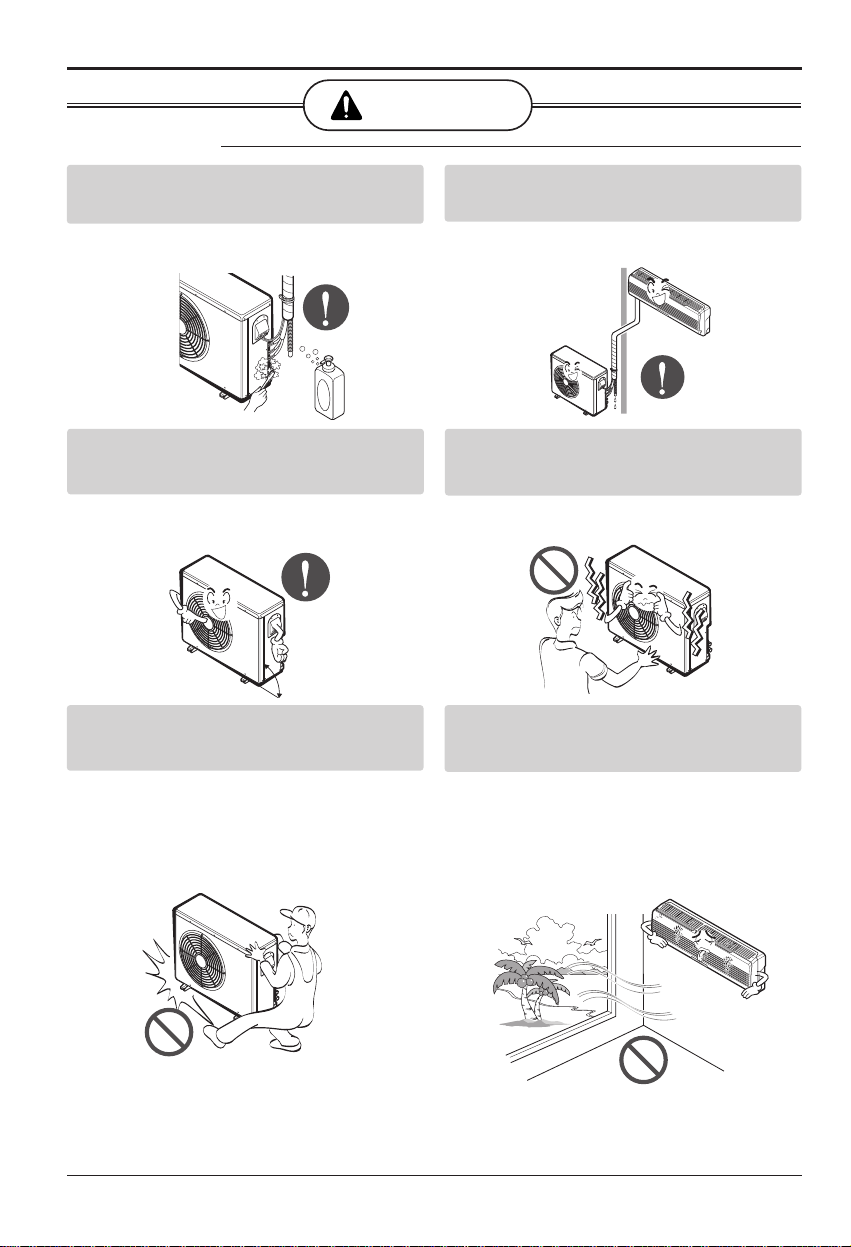
Safety Precautions
Always check for gas (refrigerant) leakage after
installation or repair of product.
• Low refrigerant levels may cause failure of
product.
Install the drain hose to ensure that water is
drained away properly.
• A bad connection may cause water leakage.
Keep level even when installing the product.
• To avoid vibration or water leakage.
Do not install the product where the noise or hot air
from the outdoor unit could damage the
neighborhoods.
• It may cause a problem for your neighbors.
Use two or more people to lift and transport the
product.
• Avoid personal injury.
Do not install the product where it will be
exposed to sea wind (salt spray) directly.
• It may cause corrosion on the product.
Corrosion, particularly on the condenser and
evaporator fins, could cause product
malfunction or inefficient operation.
CAUTION
■ Installation
90˚
Installation Manual 7
Installation of Indoor, Outdoor Unit
Installation of Indoor, Outdoor Unit
Read completely, then follow step by step.
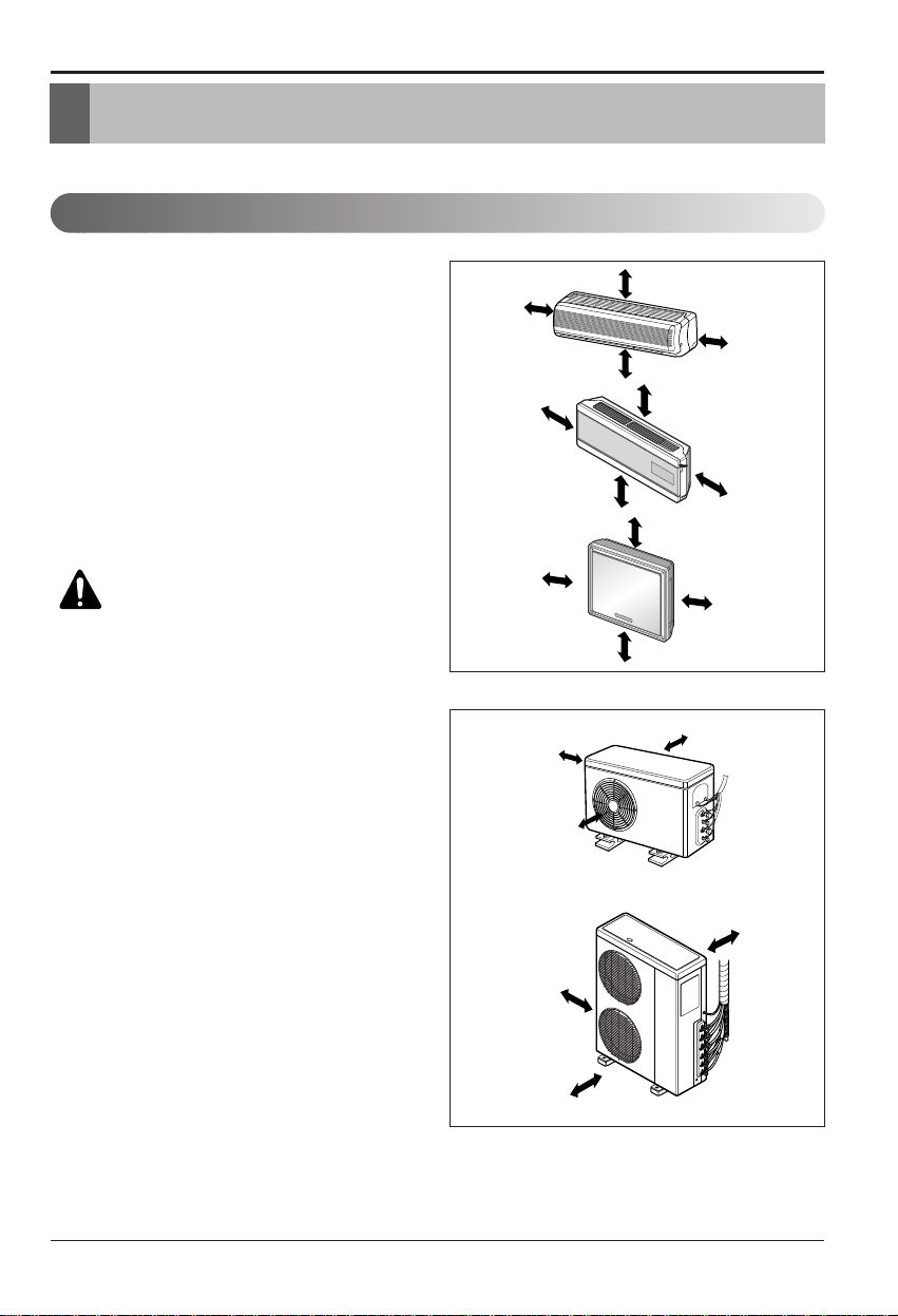
Indoor unit
1. Do not have any heat or steam near the unit.
2. Select a place where there are no obstacles
in front of the unit.
3. Make sure that condensation drainage can be
conveniently routed away.
4. Do not install near a doorway.
5. Ensure the spaces indicated by arrows from
the wall, ceiling, fence or other obstacles.
6. Use a stud finder to locate studs to prevent
unnecessary damage to the wall.
Outdoor unit
1. If an awning is built over the unit to prevent
direct sunlight or rain exposure, make sure
that heat radiation from the condenser is not
restricted.
2. Ensure that the spaces indicated by arrows
around front, back and side of the unit.
3. Do not place animals and plants in the path
of the warm air.
4. Take the air conditioner weight into account
and select a place where noise and vibration
are minimum.
5. Select a place so that the warm air and noise
from the air conditioner do not disturb
neighbors.
Rooftop Installations:
If the outdoor unit is installed on a roof
structure, be sure to level the unit. Ensure the
roof structure and anchoring method are
adequate for the unit location. Consult local
codes regarding rooftop mounting.
Select the best location
More than 5cm
More than
5cm
More than 2.3m
More than
5cm
More than 10cm
More than 5cm
More than 2.3m
More than 5cm
More than 10cm
More than 50cm
More than 2m
More than 50cm
CAUTION: Install the indoor unit
on the wall where the height from
the floors more than 2.3 meters.
more than
20cm
more than
70cm
more than
30cm
more than
70cm
more than
20cm
more than
30cm

8 Room Air Conditioner
h2
h1
h1
A
A
Branch Pipe
Main Pipe
Distributor
Distributor
B
B
h2
Multi Piping Type Distributor Type
Installation of Indoor, Outdoor Unit
Multi Piping Type (m)
DistributorType (m)
Piping length and elevation
14k/16k 30 25 15 7.5
18k 40 25 15 7.5
24k 50 25 15 7.5
30k 70 25 15 7.5
Capacity(Btu/h) Total Length Max Length(A/B)
Max Elevation
(h1)
In - In Elevation
(h2)
40k 100 50 50 15 30 10
48k 110 50 60 15 30 10
56k 120 50 70 15 30 10
Capacity
(Btu/h)
Total Length
Max Main Pipe
Length (A/B)
Total Branch
Pipe Length
Max Branch
Pipe Length
Max Elevation
(h1)
In-InElevation
(h2)
CAUTION: Capacity is based on standard length and maximum allowance
length is on the basis of reliability. Oil trap should be installed every 5~7
meters.
Installation Manual 9
Installation of Indoor, Outdoor Unit
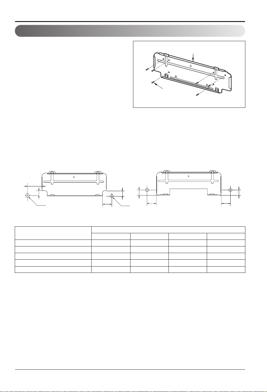
The wall you select should be strong and solid
enough to prevent vibration
1. Mount the installation plate on the wall with
type "A" screws. If mounting the unit on a
concrete wall, use anchor bolts.
• Mount the installation plate horizontally by
aligning the centerline using a level.
2. Measure the wall and mark the centerline. It
is also important to use caution concerning
the location of the installation plate-routing
of the wiring to power outlets is through the
walls typically. Drilling the hole through the
wall for piping connections must be done
safely.
How to fix installation plate
Installation Plate
Type "A" screw
SQ(7k~9k) 75 12 80 12
SR(9k~12k) 0 40 20 40
ST(18k~24k) 105 0 210 0
SZ(7k) 35 33 156 33
SU(9k~12k) 92 44 67 44
CHASSIS (Grade)
Distance (mm)
ABCD
(SQ, SR, ST, SU)
C
D
Ø70mm
Left rear piping Right rear piping
Installation plate
A
(SZ)
Installation plate
D
B
Ø70mm
C
Left rear piping Right rear piping
B
A
10 Room Air Conditioner
Installation of Indoor, Outdoor Unit
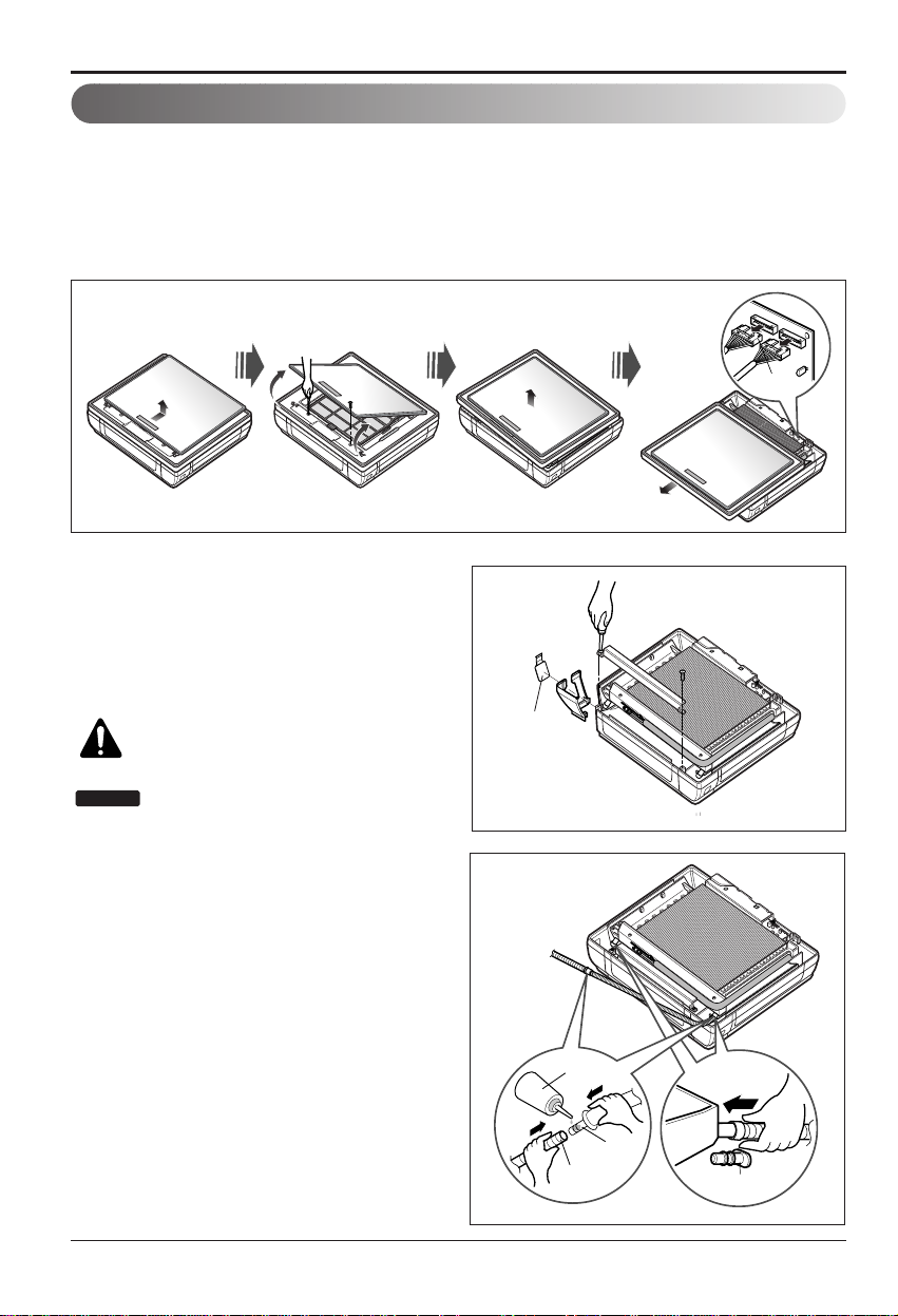
Preparing work for Installation (Artcool Type Only)
Open panel front
1. First, push the front panel backward and lift it up to remove the two screws.
2. The moment of lifting the both lower parts of panel front, you can hear sound this panel came
out, In this time panel front is separated
3. After pull down this panel a bit, and separate connecting wire with product.
Remove cover pipe and cover side
1. Remove two screws(for fixing cover pipe)
2. Pull up the cover side of desired connecting
direction, then cover side is separated.
3. In case of connecting direction is left or right,
path through the hole of cover side.
CAUTION: After removing the pipe
hole, cut the burr for safety.
When connecting pipe path through rear
wall, don’t remove the hole.
NOTICE
Drain hose junction
1. Remove the rubber stopple of desired
direction of drainage.
2. As the following picture, Insert drain hose in
the handle of drain pan, and join drain hose
and connecting hose.
Panel Front
Connector
Pipe hole
Adhesive
Drain
hose
Connecting
part
Only one
desiring direction
rubber cap
 Loading...