


P/NO : MFL39817320
www.lg.com
INSTALLATION MANUAL
AIR CONDITIONER
• Please read this installation manual completely before installing the product.
• Installation work must be performed in accordance with the national wiring
standards by authorized personnel only.
• Please retain this installation manual for future reference after reading it
thoroughly.
TYPE : Multi Type

Multi Type Air Conditioner Installation Manual
CONTENTS
Installation Parts Provided.........................................3
Safety Precautions..................................................4~5
Installation of indoor, outdoor unit .......................6~9
Flaring work and connection of piping.............10~17
Connecting the Cable between Indoor Unit and
Outdoor Unit ........................................................18~20
Checking the Drainage, Forming the Pipings
and Long pipe Setting ........................................21~24
Air Purging and Evacuation...............................24~26
Installation PI485.......................................................26
Test running...............................................................28
Installation guide at the seaside..............................29
o Level gauge
o Screw driver
o Electric drill
o Hole core drill (ø65mm)
o Horizontal meter
o Flaring tool set
o Specified torque wrenches
1.8kg.m, 4.2kg.m, 5.5kg.m, 6.6kg.m
(different depending on model No.)
o Spanner .................Half union
o A glass of water
o Screw driver
o Hexagonal wrench(4mm)
o Gas-leak detector
o Vacuum pump
o Gauge manifold
o Owner's manual
o Thermometer
o Holder Remote Control
Installation Requirements
Required Tools
2 Multi Air Conditioner
Installation Parts Provided
Installation Manual 3
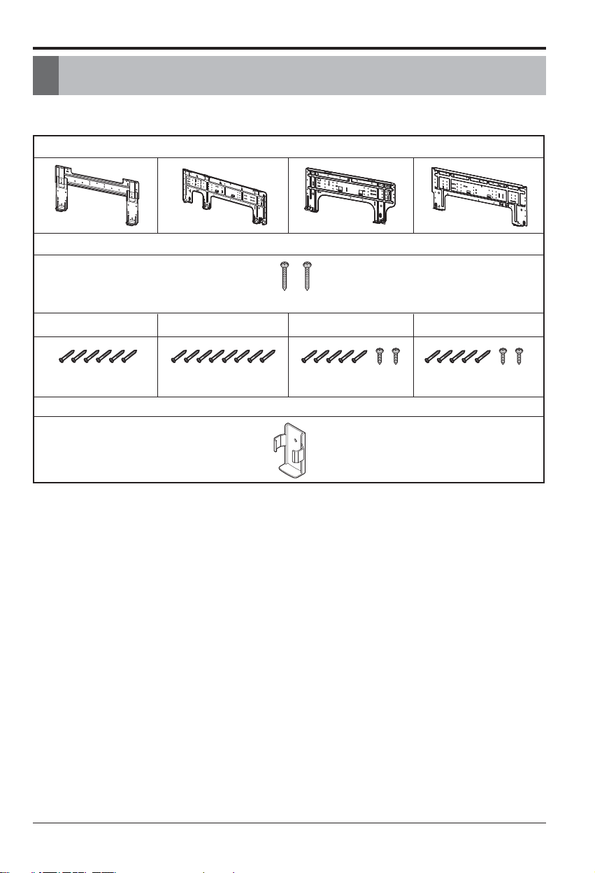
Installation Parts Provided
Standard Type
Installation plate
Type "B" screws
(2EA)
Type "A" screw Type "A" screw Type "A" and "C" screw Type "A" and "C" screw
(6 EA) (8 EA) (5 EA) (2 EA) (5 EA) (2 EA)
Holder Remote Control

Safety Precautions
Do not disassemble or repair the product.
• Contact your dealer or service center.
Always earth the product.
• It will cause fire or electric shock.
Do not handle the flamable gas or explosive
materials near the product.
• Otherwise, it may cause fire or failure of
product.
Do not install where flamable gas could
leak.
• Otherwise, it may cause esplosion or fire.
Do not install the product on a defected
installation stand.
• Otherwise, It may cause injury or accident.
Be cautious when unpacking and installing
the product.
• Sharp edges could cause injury.
Do not use damaged power cable.
• It will cause fire or electric shock.
Always intstall a circuit breaker and main
breaker.
• No installation may cause fire and electric
shock.
For installation, always contact the dealer
or service center.
• Otherwise, it may cause fire, electric shock,
explosion or injury."
For electric work, contact the dealer or
service center.
• Otherwise, It will cause fire or electric shock.
To prevent injury to the user or other people and property damage, the following instructions
must be followed.
n Incorrect operation due to ignoring instruction will cause harm or damage. The seriousness
is classified by the following indications.
n Meanings of symbols used in this manual are as shown below.
WARNING
CAUTION
This symbol indicates the possibility of death or serious injury.
This symbol indicates the possibility of injury or damage.
WARNING
Be sure not to do.
Be sure to follow the instruction.
Safety Precautions
4 Multi Air Conditioner
Safety Precautions
Do not put the heater, etc. near the power
cable.
• Otherwise, it may cause fire and electric shock.
Cover the electric part.
• Otherwise, it may cause fire or electric shock.
Do not turn the breaker on/off during
operation.
• Otherwise, it may cause fire or electric shock.
Do not open the suction inlet of the product
during operation.
• Otherwise, it may cause electric shock or
failure.
Do not touch the metal parts of the product
when removing the air filter.
• Otherwise, it may cause personal injury.
Do not step or put anyting on the product.
• Otherwise, it may cause personal injury and
failure of product.
Always inspect gas leakage after
installation and repair of product.
• Otherwise, it may cause failure of product.
Install the drain hose to ensure that drain
can be securely done.
• Otherwise, it may cause water leakage.
Keep the level even while installing the
product.
• Otherwise, it may cause vibration or water
leakage.
Do not install the product where the noise
or hot wind from the outdoor unit could
give any casualty to the neighborhood
• Otherwise, it may cause dispute with the
neighborhoods.
Do not touch(operate) product with wet
hands.
• Otherwise, it may cause fire or electric shock.
If strange sound, smell or smoke come from
product, turn the breaker off.
• Otherwise, it may cause electric shock or fire.
CAUTION
Fix the outdoor unit on the floor.
• Otherwise, it can be blown away by the strong
wind. It will cause injury or accident.
Installation Manual 5
6 Multi Air Conditioner
Installation of Indoor, Outdoor Unit
Installation of Indoor, Outdoor Unit
Read completely, then follow step by step.
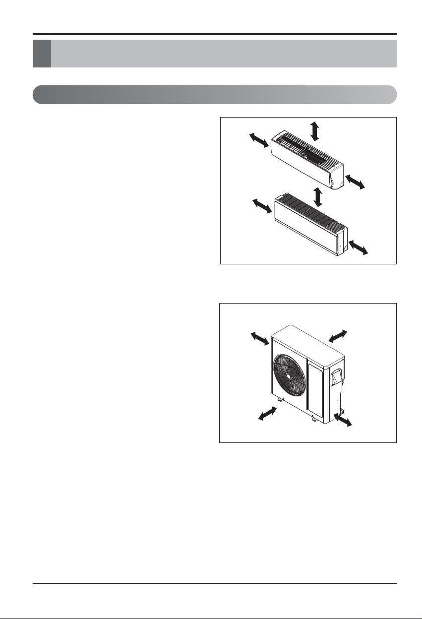
Indoor unit
1. Do not allow any heat or steam to be near
the unit.
2. Select a place where there are no obstacles
in front of the unit.
3. Make sure that condensation drainage can
be conveniently routed outdoors.
4. Install as far away from a doorway as
possible for better performance.
5. Ensure the unit is unobstructed, allow proper
space on all sides according to the arrows
and distance measurements in the figure at
right.
6. Use a stud finder to locate studs to prevent
unnecessary damage to the wall.
Outdoor unit
1. If an awning is built over the unit to prevent
direct sunlight or rain exposure, make sure
that heat radiation from the heat pump is not
restricted.
2. Ensure the unit is unobstructed, allow proper
space on all sides according to the arrows
and distance measurements in the figure at
right.
3. Do not allow animals or plants to remain the
in path of the discharging warm air.
4. Take the air conditioner weight into account
and select a place where noise and vibration
are minimum.
5.
Select a place so that the warm air and sound
from the air conditioner does not disturb
neighbors.
Rooftop Installations:
If the outdoor unit is installed on a rooftop, be
sure to level the unit. Ensure the rooftop and
anchoring method are adequate for the unit
location. Consult local codes regarding rooftop
mounting.
Select the best location
More than
700mm
More than
300mm
More than
300mm
More than
600mm
Select the best location
h The figure may be slightly different according
to the model.
More than 200mm
More than
100mm
More than
100mm
More than
100mm
More than 200mm
More than
100mm
Installation Manual 7
Installation of Indoor, Outdoor Unit
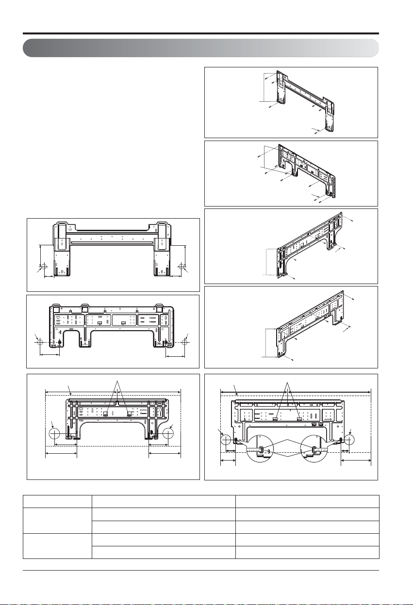
The wall you select should be strong and
solid enough to prevent vibration
1. Mount the installation plate on the wall with
type "A" screws. If mounting the unit on a
concrete wall, use anchor bolts.
• Mount the installation plate horizontally by
aligning the centerline using a level.
2. Measure the wall and mark the centerline.
It is also important to use caution
concerning the location of the installation
plate-routing of the wiring to power outlets
is through the walls typically. Drilling the
hole through the wall for piping connections
must be done safely.
Fixing Installation Plate
(Unit : mm)
Indoor Type Capacity (kBtu/h) Type
Wall mounted
9,12 3
18,24 4
ART COOL Mirror
9,12 1
18,24 2
110
Ø70
90
Left rear piping Right rear piping
Ø70
133
Left rear piping Right rear piping
Unit Outline
Installation plate
<Type 1>
Installation plate
<Type 2>
Place a level on raised tab
442 442
100
110
Ø70
70
Ø70
<Type 1>
<Type 2>
<Type 3>
<Type 4>
Unit Outline
Installation Plate
Chassis
Hook
Type “A”
Installation Plate
Chassis
Hook
Type “A”
Installation Plate
Chassis
Hook
Installation Plate
Chassis
Hook
Place a level on raised tab
460 570
Type "A" Screws
Type "A" Screws
Left
rear
piping
Ø70
Installation Plate
133
175
<Type 3>
Ø70
95
217
Right
rear
piping
Ø70
Left
rear
piping
105
Installation Plate
Measuring Tape
69
Measuring Tape
Hanger
<Type 4>
Ø70
Right
rear
56
piping
207
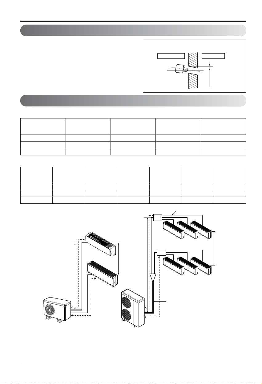
h2
h1
h1
A
A
Branch Pipe
Main Pipe
Distributor
Distributor
B
B
h2
Multi Piping Type Distributor Type
Installation of Indoor, Outdoor Unit
Piping length and elevation
Multi Piping Type (Unit: m)
Distributor Type (Unit: m)
18 50 25 15 7.5
26 70 25 15 7.5
30 70 25 15 7.5
Capacity(kBtu/h) Total Length Max Length(A/B)
Max Elevation
(h1)
In - In Elevation
(h2)
40 100 50 50 15 30 15
48 135 55 80 15 30 15
56 145 55 90 15 30 15
Capacity
(kBtu/h)
Total Length
Max Main Pipe
Length (A/B)
Total Branch
Pipe Length
Max Branch
Pipe Length
Max Elevation
(h1)
In - In Elevation
(h2)
• Drill the piping hole with a ø70mm hole core
drill. Drill the piping hole at either the right or
the left with the hole slightly slanted to the
outdoor side.
Drill a hole in the wall
8 Multi Air Conditioner
Standard / Artcool Mirror type
Indoor
WALL
Outdoor
5-7mm
Refrigerant charge
The calculation of the additional charge should be taken in account for the length of extra pipe.
Additional Charge Calculation Example-1
Model
Standard
length(m)
Max piping for
one room(m)
Max total Piping
Length(m)
Additional
Charge(g/m)
18 7.5 25 50 20
26 7.5 25 70 20
30 7.5 25 70 20
Multiple Piping Models
Model
Main Piping length Branch piping length
Standard
length(m)
Additional
refrigerant(g/m)
Standard
length(m)
Additional
refrigerant(g/m)
40 5 50 5 20
48 5 50 5 20
56 5 50 5 20
Distributor type Models
Installation Manual 9
Installation of Indoor, Outdoor Unit
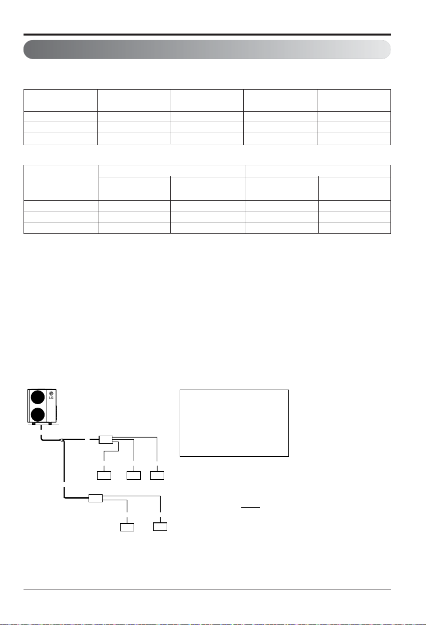
■ Multiple Piping Models
Additional charge (g) = ((A Room Installation Length – Standard Length ) x 20g/m
❈ CF = Max. number of connectable indoor unit – Total number of connected indoor unit
+ (B Room Installation Length – Standard Length ) x 20g/m +.. )
- CF(Correction Factor) x 150
■ Distributor type Models
Additional charge (g) = (( Total Main piping Length - Main Standard Length ) x 50g/m
❈ CF = Max. number of connectable indoor unit – Total number of connected indoor unit
+ (A Room Branch Length – Standard Length ) x 20g/m
+ (B Room Branch Length – Standard Length ) x 20g/m
+ (C Room Branch Length – Standard Length ) x 20g/m +.. )
- CF(Correction Factor) x 100
• Total main pipe(A+B+C) = 30m
• Each branch pipe
Ex) A7UQ406FA1
A
A
C
abc
9k 9k 9k
B
d
9k
a = 10m
b = 8m
c = 5m
d = 3m
e = 10m
❖
Additional Charge
=((30-5) x 50 + (10-5) x 20 + (8-5) x 20
+ (5-5) x 20 + (3-5) x 20 + (10-5) x 20)
- (7-5) x 100 = 1270g
e
9k

Flaring Work and Connection of Piping
Flaring Work and Connection of Piping
Flaring work
Main cause for gas leakage is due to defect in flaring work. Carry out correct flaring work in the
following procedure.
Cut the pipes and the cable.
1. Use the piping kit accessory or the pipes
purchased locally.
2. Measure the distance between the indoor and
the outdoor unit.
3. Cut the pipes a little longer than measured
distance.
4. Cut the cable 1.5m longer than the pipe length.
Burrs removal
1. Completely remove all burrs from the cut cross
section of pipe/tube.
2. Put the end of the copper tube/pipe in a
downward direction as you remove burrs in
order to avoid dropping burrs into the tubing.
Putting nut on
• Remove flare nuts attached to indoor and
outdoor unit, then put them on pipe/tube having
completed burr removal.
(not possible to put them on after flaring work)
Flaring work
• Carry out flaring work using flaring tool as shown
below.
• Firmly hold copper pipe in a die in the dimension
shown in the table above.
Copper
pipe
90°
Slanted Uneven Rough
Pipe
Reamer
Point down
Flare nut
Copper tube
Bar
Copper pipe
Clamp handle
Red arrow mark
Cone
Yoke
Handle
Bar
"A"
mm inch mm
Ø6.35 1/4 1.1~1.3
Ø9.52 3/8 1.5~1.7
Ø12.7 1/2 1.6~1.8
Ø15.88 5/8 1.6~1.8
Ø19.05 3/4 1.9~2.1
Outside diameter A
10 Multi Air Conditioner
 Loading...