

LG A3UH216FA0, A2UC186FA0, A4UH306FA0, A3UC216FA0, AMNC076LQL0 Service Manual
...
LG
Free Joint Multi Type
Air Conditioner
SERVICE MANUAL
LG
CAUTION
website http://www.lgservice.com
e-mail http://www.lgeservice.com/techsup.html
• BEFORE SERVICING THE UNIT, READ THE SAFETY
PRECAUTIONS IN THIS MANUAL.
• ONLY FOR AUTHORIZED SERVICE PERSONNEL.
MODEL Cooling Model Heating Model
• Outdoor Unit: A2UC146FA0 A2UH146FA0
A2UC186FA0 A2UH186FA0
A3UC216FA0 A3UH216FA0
A4UC306FA0 A4UH306FA0
• Indoor Unit: AMNC076LQL0 AMNH076LQL0
AMNC096LQL0 AMNH096LQL0/LQA0
AMNC126LRL0 AMNH126LRL0
AMNC186LTL0 AMNH186LTL0
AMNC246LTL0 AMNH246LTL0/LTA0
AMNC096AP*1 AMNH096AP*1
AMNC126AP*1 AMNH126AP*1

2 Free Joint Multi Air Conditioner
Multi Air Conditioner Service Manual
TABLE OF CONTENTS
Safety Precautions......................................................................................................................................3
Details of LG Model Name..........................................................................................................................7
Product Specifications
......................................................................................................................................8
Combination Table....................................................................................................................................11
Dimensions
........................................................................................................................................................17
Refrigeration Cycle Diagram.............................................................................................................................22
Wiring Diagram...................................................................................................................................................26
Electronic Control Device..................................................................................................................................29
Schematic Diagram ...........................................................................................................................................32
Functions ............................................................................................................................................................35
Operation Details................................................................................................................................................39
2-way, 3-way Valve..............................................................................................................................................46
Cycle Troubleshooting Guide............................................................................................................................50
Electronic Parts Troubleshooting Guide..........................................................................................................52
Disassembly of the parts (Indoor unit).............................................................................................................58
Exploded View & Replacement Parts List........................................................................................................61
Service Manual 3
Safety Precautions
Safety Precautions
To prevent injury to the user or other people and property damage, the following instructions must
be followed.
■ Incorrect operation due to ignoring instruction will cause harm or damage. The seriousness is
classified by the following indications.
■ Meanings of symbol used in this manual are as shown below.
WARNING
CAUTION
This symbol indicates the possibility of death or serious injury.
This symbol indicates the possibility of injury or damage.
WARNING
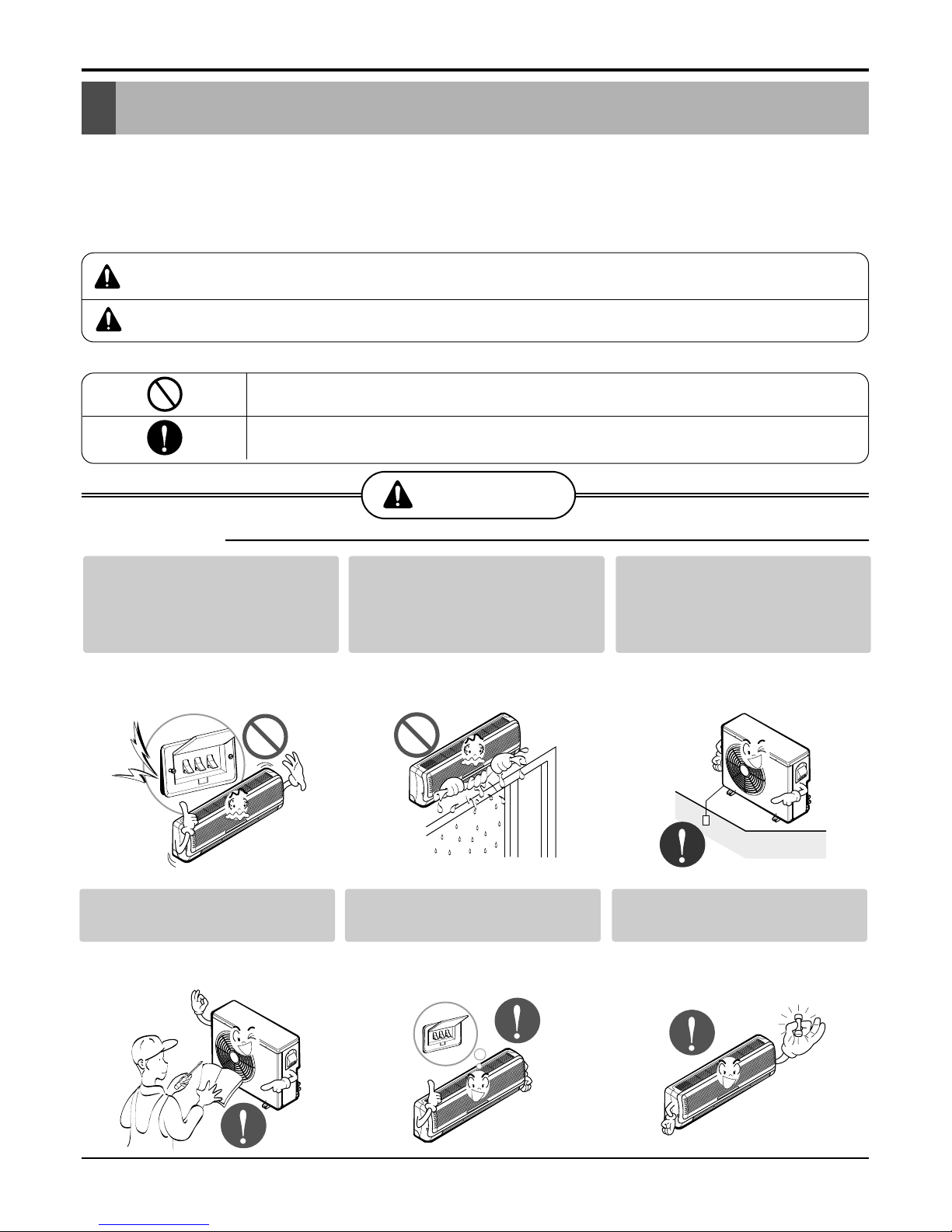
■ Installation
Be sure not to do.
Be sure to follow the instruction.
Do not use a defective or
underrated circuit breaker.
Use this appliance on a dedicated circuit.
• There is risk of fire or electric shock.
Do not let the air conditioner
run for a long time when the
humidity is very high and a
door or a window is left open.
• Moisture may condense and wet or
damage furniture.
Always ground the product.
• There is risk of fire or electric shock.
Install the panel and the cover
of control box securely.
• There is risk of fire or electric shock.
Always install a dedicated circuit and breaker.
• Improper wiring or installation may
cause fire or electric shock
Use the correctly rated breaker or fuse.
• There is risk of fire or electric shock.
4 Free Joint Multi Air Conditioner
Safety Precautions
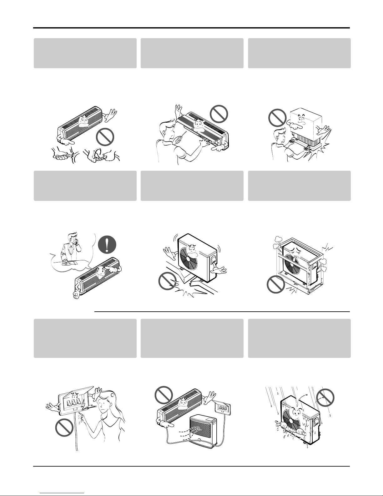
■ Operational
Do not modify or extend the
power cable.
• There is risk of fire or electric shock.
Do not install, remove, or reinstall the unit by yourself
(customer).
• There is risk of fire, electric shock,
explosion, or injury.
Be cautious when unpacking
and installing the product.
• Sharp edges could cause injury. Be
especially careful of the case edges
and the fins on the condenser and
evaporator.
For installation, always contact the dealer or an
Authorized Service Center.
• There is risk of fire, electric shock,
explosion, or injury.
Do not install the product on a
defective installation stand.
• It may cause injury, accident, or damage to the product.
Be sure the installation area
does not deteriorate with age.
• If the base collapses, the air conditioner could fall with it, causing property
damage, product failure, and personal
injury.
Do not touch(operate) the
product with wet hands.
• There is risk of fire or electrical shock.
Do not place a heater or other
appliances near the power
cable.
• There is risk of fire and electric shock.
Do allow water to run into
electric parts.
• It may cause There is risk of fire, failure of the product, or electric shock.
Service Manual 5
Safety Precautions
Do not open the inlet grille of the product during operation. (Do not touch the electrostatic
filter, if the unit is so equipped.)
• There is risk of physical injury, electric shock, or product failure.
Be cautious that water could not enter the
product.
• There is risk of fire, electric shock, or product damage.
Do not store or use flammable gas or combustibles near the product.
• There is risk of fire or failure of product.
If strange sounds, or smell or smoke comes
from product. Turn the breaker off or disconnect the power supply cable.
• There is risk of electric shock or fire.
Gasolin
6 Free Joint Multi Air Conditioner
■ Operational
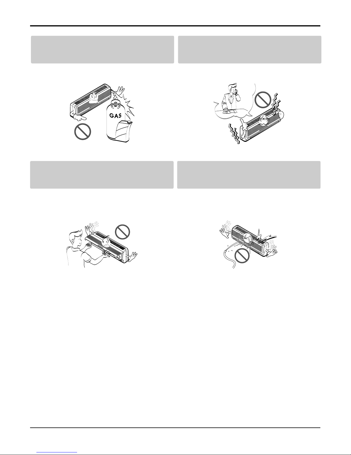
Safety Precautions
Use two or more people to lift
and transport the product.
• Avoid personal injury.
Use a soft cloth to clean. Do
not use harsh detergents, solvents, etc.
• There is risk of fire, electric shock, or
damage to the plastic parts of the product.
Do not touch the metal parts
of the product when removing
the air filter. They are very
sharp!
• There is risk of personal injury.
Do not step on or put anyting on the product.
(outdoor units)
• There is risk of personal injury and failure of product.
Do not insert hands or other objects through
the air inlet or outlet while the product is operated.
• There are sharp and moving parts that could cause personal
injury.
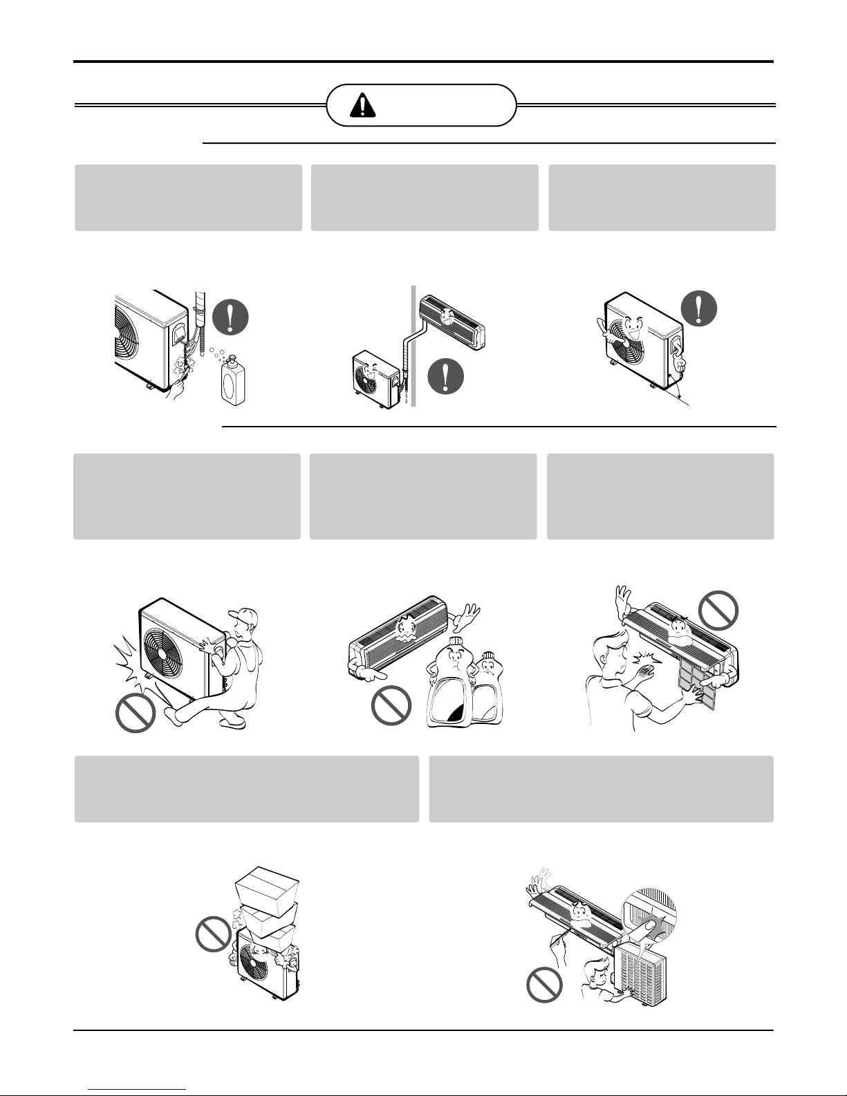
CAUTION
■ Installation
Wax
Thinner
check for gas (refrigerant)
leakage after installation or
repair of product.
• Low refrigerant levels may cause failure of product.
Install the drain hose to
ensure that water is drained
away properly.
• A bad connection may cause water
leakage.
Keep level even when
installing the product.
• To avoid vibration or water leakage.
90˚
Details of LG Model Name
Details of LG Model Name
Outdoor Unit
A3UH216FA0
A: Basic
3: One outdoor unit can connect with three indoor
units(Reference to combination table)
Max. No. of indoor units
Development Sequence
Function
F: Free joint multi
Multi Type
14: 14,000 Btu/h 18: 18,000 Btu/h
21: 21,000 Btu/h 30: 30,000 Btu/h
Capacity
C: Cooling only H: Heat pump
Model Type
U: Outdoor N: Indoor
Outdoor / Indoor
A: Changwon of korea / R410A
Making place / Refrigerant
6: 220-240V~ / 50Hz / 1Ø
Electric Standard (Volts / Freq. / Phase)
AMNH076LQL0
A: Basic L: Plasma + 2way M: Plasma + 4way
B: Blue M: metal D: Wood
Development Sequence
Function & Color
A: Changwon of korea / R410A
Making place / Refrigerant
Indoor Unit
Q: SQ chassis T: ST chassis
R: SR chassis P: SP1 chassis
Chassis Type
L: SQ/SR/ST chassis L look
A: SP1 chassis general / wide look
Type
6: 220-240V~ / 50Hz / 1Ø
Electric standard (Volts / Freq. /Phase)
07: 7,000 Btu/h 09: 9,000 Btu/h
12: 12,000 Btu/h 18: 18,000 Btu/h
24: 24,000 Btu/h
Capacity
C: Cooling only
H: Heat pump
Model Type
U: Outdoor
N: Indoor
Outdoor / Indoor
M: Multi
Multi Type
Service Manual 7
8 Free Joint Multi Air Conditioner
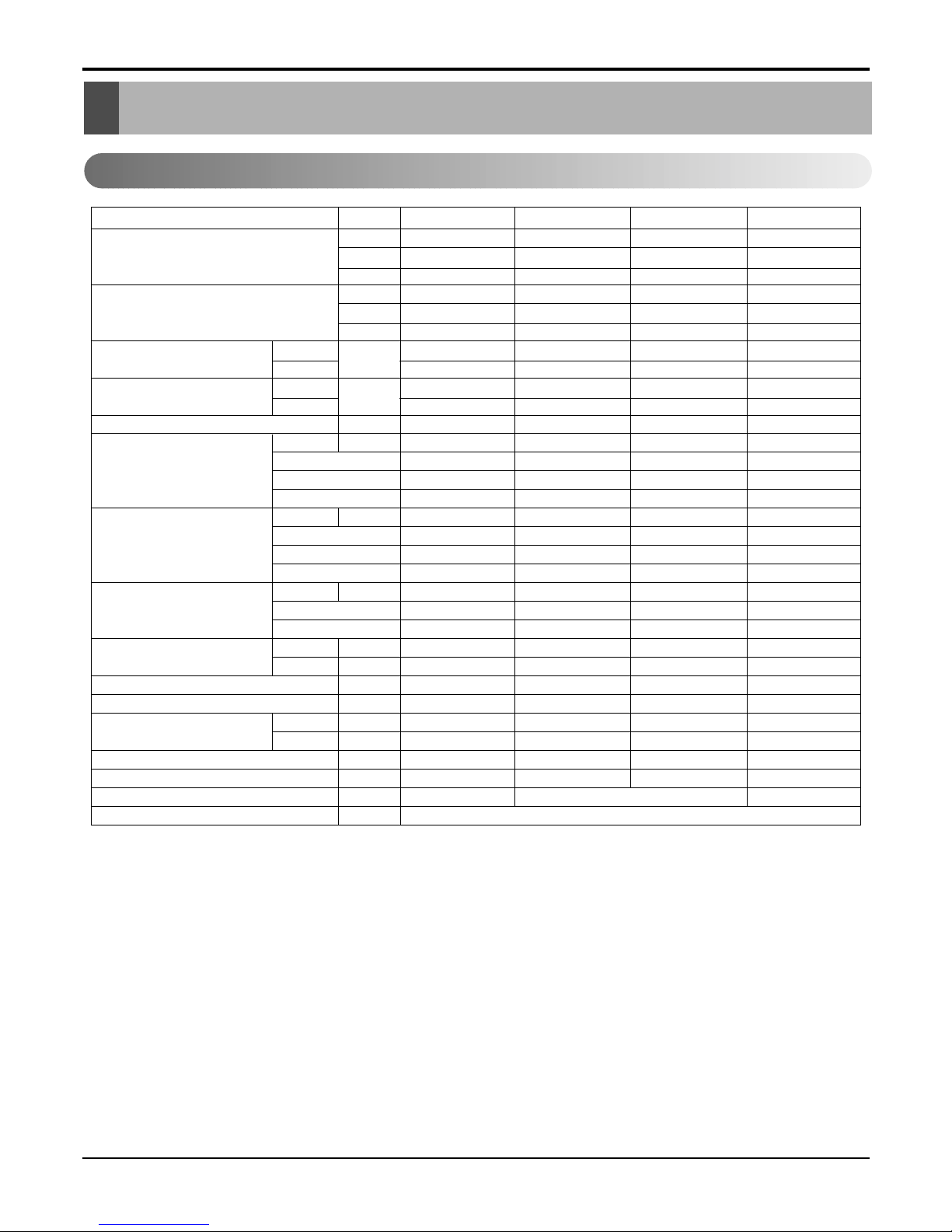
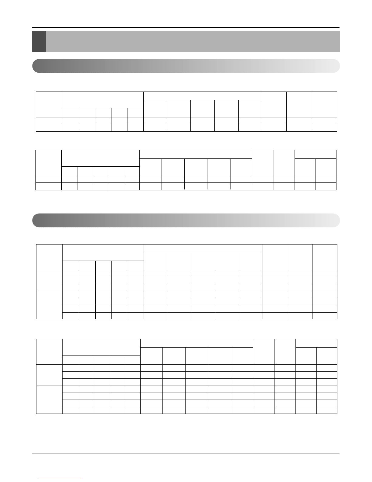
Product Specifications
Product Specifications
1. Outdoor_Heat Pump
Model
kcal/hr
Cooling Capacity ★ W
Btu/hr
kcal/hr
Heating Capacity ★ W
Btu/hr
Input ★
Cooling
W
Heating
Running Current ★
Cooling
A
Heating
Power Supply Ø,V,Hz
L.R.A A
Compressor A
Type
Oil Type
O.L.P Type
L.R.A A
Compressor B
Type
Oil Type
O.L.P Type
Charge g
Refrigerant Type
Control
Fan Motor Output W
Capacitor µF/Vac
Air Circulation m3/min
Noise Level(Sound Press,1m)
dBA(Hi/Lo)
Piping Connection Liquid inch(mm)
Gas inch(mm)
Dimensions (W*H*D) mm
Net Weight kg
Power Supply Cable No.* mm
2
Interunit Cable No.* mm
2
2369~3629 1764~4536 2016~5292 2268~7560
2755~4220 2051~5275 2345~6154 2638~8792
9400~14400 7000~18000 8000~21000 9000~30000
2520~3679 2268~4990 2268~5292 2520~8316
2931~4279 2638~5803 2638~6154 2931~9671
10000~14600 9000~19800 9000~21000 10000~33000
1300~1500 780~1900 880~2100 1100~3250
1300~1500 1200~1900 1350~2200 1310~3600
6.1~6.6 3.5~8.5 4.0~9.4 4.8~15
6.0 ~ 7.0 5.5~8.5 6.0~9.8 6.0~16.5
1,220-240,50 1,220-240,50 1,220-240,50 1,220-240,50
37 24 25.2 35.5
Rotary Rotary Rotary Rotary
FVS68D(PVE) FV50S(PVE) FV50S(PVE) FV50S(PVE)
Internal MRA98781-9090 MRA99150-9090 Internal
- 17.2 20.3 25.2
- Rotary Rotary Rotary
- FV50S(PVE) FV50S(PVE) FV50S(PVE)
- MRA99901-9090 MRA99282-9090 MRA99150-9090
1100 (at 7.5m) 1350 (at 7.5m) 1500 (at 7.5m) 2500 (at 7.5m)
R410A R410A R410A R410A
Capiilary Tube L.E.V L.E.V L.E.V
27 67.2 67.2 41
1.5/400 6/370 6/370 2/370
40(1412) 53(1872) 53(1872) 63(2225)
52 53 53 54/51
1/4(6.35)*2EA 1/4(6.35)*2EA 1/4(6.35)*3EA 1/4(6.35)*4EA
3/8(9.52)*2EA 3/8(9.52)*2EA 3/8(9.52)*3EA 3/8(9.52)*4EA
801 x 555 x 262 870 x 655 x 320 870 x 655 x 320 870 x 1060 x 320
45 64 64 80
3*2.5(Includes earth)
3*2.5(Includes earth)
3*3.5(Includes earth)
4*0.75(Includes earth)
A2UH146FA0 A2UH186FA0 A3UH216FA0 A4UH306FA0
★ : See Page "Combination Table"
Service Manual 9
Product Specifications
2. Outdoor_Cooling Only
Model
kcal/hr
Cooling Capacity ★ W
Btu/hr
Input ★ Cooling W
Running Current ★ Cooling A
Power Supply Ø,V,Hz
L.R.A A
Compressor A
Type
Oil Type
O.L.P Type
L.R.A A
Compressor B
Type
Oil Type
O.L.P Type
Charge g
Refrigerant Type
Control
Fan Motor Output W
Capacitor µF/Vac
Air Circulation m3/min
Noise Level(Sound Press,1m)
dBA(Hi/Lo)
Piping Connection
Liquid inch(mm)
Gas inch(mm)
Dimensions (W*H*D) mm
Net Weight kg
Power Supply Cable No.* mm
2
Interunit Cable No.* mm
2
2369~3629 1764~4536 2016~5292 2268~7560
2755~4220 2051~5275 2345~6154 2638~8792
9400~14400 7000~18000 8000~21000 9000~30000
1300~1500 780~1900 880~2100 1100~3250
6.0~7.0 3.5~8.5 4.0~9.4 4.8~15
1,220-240,50 1,220-240,50 1,220-240,50 1,220-240,50
37 24 25.2 35.5
Rotary Rotary Rotary Rotary
FVS68D(PVE) FV50S(PVE) FV50S(PVE) FV50S(PVE)
Internal MRA98781-9090 MRA99150-9090 Internal
- 17.2 20.3 25.2
- Rotary Rotary Rotary
- FV50S(PVE) FV50S(PVE) FV50S(PVE)
- MRA99901-9090 MRA99282-9090 MRA99150-9090
1050 (at 7.5m) 1350 (at 7.5m) 1500 (at 7.5m) 2500 (at 7.5m)
R410A R410A R410A R410A
Capiilary Tube L.E.V L.E.V L.E.V
27 67.2 67.2 41
1.5/400 6/370 6/370 2/370
40(1412) 53(1872) 53(1872) 63(2225)
52 53 53 54/51
1/4(6.35)*2EA 1/4(6.35)*2EA 1/4(6.35)*3EA 1/4(6.35)*4EA
3/8(9.52)*2EA 3/8(9.52)*2EA 3/8(9.52)*3EA 3/8(9.52)*4EA
801 x 555 x 262 870 x 655 x 320 870 x 655 x 320 870 x 1060 x 320
45 64 64 80
3*2.5(Includes earth)
3*2.5(Includes earth)
3*3.5(Includes earth)
4*0.75(Includes earth)
A2UC146FA0 A2UC186FA0 A3UC216FA0 A4UC306FA0
★ : See Page "Combination Table"
10 Free Joint Multi Air Conditioner
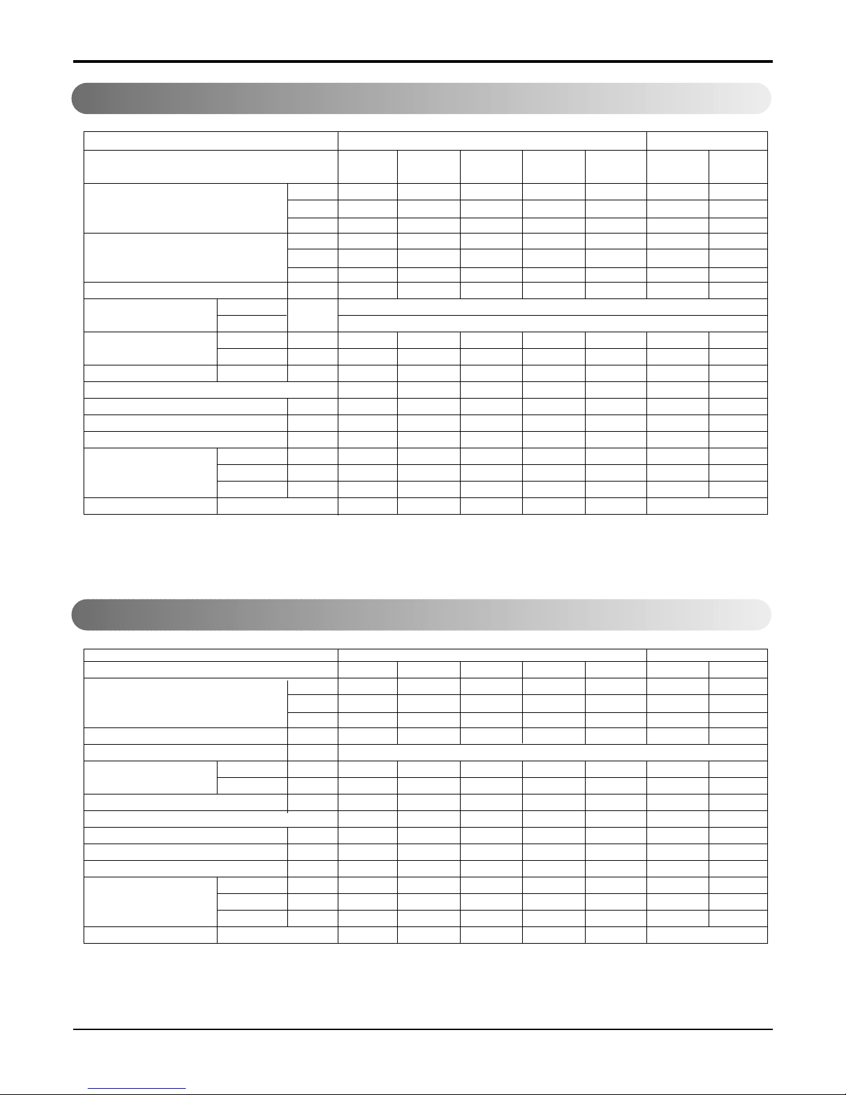
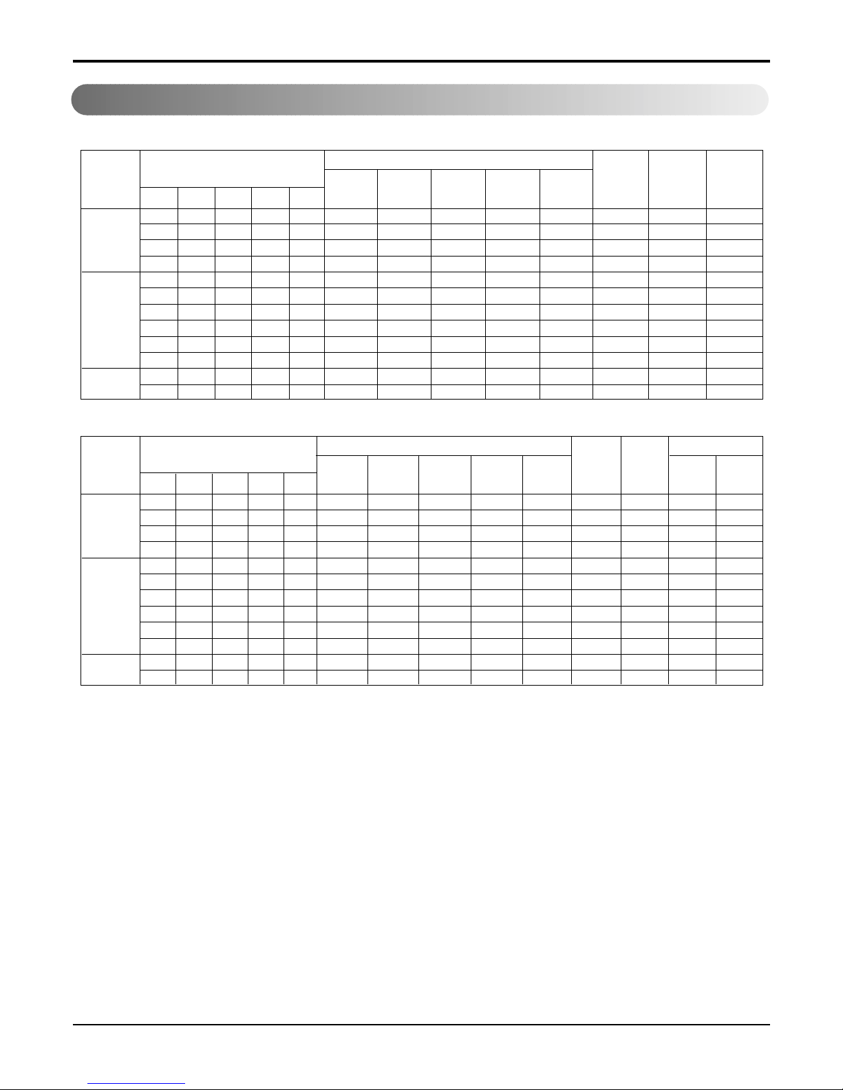
Product Specifications
3. Indoor_Heat Pump
4. Indoor_Cooling Only
Indoor Unit Type
Model
kcal/hr
Nominal Cooling Capacity ★ W
Btu/hr
kcal/hr
Nominal Heating Capacity ★ W
Btu/hr
Air Circulation m3/min
Setting temperature Cooling
˚C
range Heating
Fan Motor
Output W
Capacitor µF/Vac
Noise Level(Sound Press, 1m)
H/M/L dBA
Temperature controller
Dehumidification Rate l/h
Dimensions (W x H x D) mm
Net Weight kg
Liquid inch(mm)
Piping Connection Gas inch(mm)
Drain hose(OD Ø)
mm
Front Panel Color " * " Position
1764 2267 2772 4536 5796 2267 2772
2051 2638 3224 5275 6741 2638 3224
7000 9000 12000 18000 23000 9000 12000
1940 2495 3049 4990 6426 2495 3049
2257 2901 3546 5803 7473 2901 3546
7700 9900 13200 19800 25500 9900 13200
5.5 6.0 9 13 14 7.5 8.5
18~30
16~30
8 8 14 22 29 24 24
0.9 / 400 0.9 / 400 0.9 / 400 2.0 / 370 2.0 / 370 - -
35 / 32 / 29 37 / 33 / 31 39 / 36 / 34 42 / 39 / 36 46 / 43 / 39 38 / 35 /32 43 / 40 / 33
Thermistor Thermistor Thermistor Thermistor Thermistor Thermistor Thermistor
1 1.2 1.7 1.9 2.2 1 1.2
820x260 x155 820x260x155 900x285x156 1080x314x182 1080x314x182 570x568x137 570x568x137
778121299
1/4 (6.35) 1/4 (6.35) 1/4 (6.35) 1/4 (6.35) 1/4 (6.35) 1/4 (6.35) 1/4 (6.35)
3/8 (9.52) 3/8 (9.52) 3/8 (9.52) 1/2 (12.7) 1/2 (12.7) 3/8 (9.52) 3/8 (9.52)
20 20 20 20 20 20 20
- - - - - M:Metal, B:Blue, D:Wood
AMNH076LQL0
AMNH096LQL0
AMNH096LQA0
AMNH126LRL0 AMNH186LTL0
AMNH246LTL0
AMNH246LTA0
AMNH096AP*1 AMNH126AP*1
★ : See Page "Combination Table"
Wall Mounted
Art Cool
Indoor Unit Type
Model
kcal/hr
Nominal Cooling Capacity ★ W
Btu/hr
Air Circulation m3/min
Setting temperature range(cool) ˚C
Fan Motor
Output W
Capacitor µF/Vac
Noise Level(Sound Press, 1m)
H/M/L dBA
Temperature controller
Dehumidification Rate l/h
Dimensions (W x H x D) mm
Net Weight kg
Liquid inch(mm)
Piping Connection
Gas inch(mm)
Drain hose(OD Ø)
mm
Front Panel Color " * " Position
1764 2267 2772 4536 5796 2267 2772
2051 2638 3224 5275 6741 2638 3224
7000 9000 12000 18000 23000 9000 12000
5.5 6.0 9 13 14 7.5 8.5
18~30
8.4 8.4 14.4 22 29 24 24
0.9 / 400 0.9 / 400 0.9 / 400 2.0 / 370 2.0 / 370 - -
35 / 32 / 29 37 / 33 / 31 39 / 36 / 34 42 / 39 / 36 46 / 43 / 39 38 / 35 /32 43 / 40 / 33
Thermistor Thermistor Thermistor Thermistor Thermistor Thermistor Thermistor
1 1.2 1.7 1.9 2.2 1 1.2
820x260x155 820x260x155 900x285x156 1080x314x182 1080x314x182 570x568x137 570x568x137
778121299
1/4 (6.35) 1/4 (6.35) 1/4 (6.35) 1/4 (6.35) 1/4 (6.35) 1/4 (6.35) 1/4 (6.35)
3/8 (9.52) 3/8 (9.52) 3/8 (9.52) 1/2 (12.7) 1/2 (12.7) 3/8 (9.52) 3/8 (9.52)
20 20 20 20 20 20 20
- - - - - M:Metal, B:Blue, D:Wood
AMNC076LQL0 AMNC096LQL0 AMNC126LRL0 AMNC186LTL0 AMNC246LTL0 AMNC096AP*1 AMNC126AP*1
★ : See Page "Combination Table"
Wall Mounted Art Cool
Service Manual 11
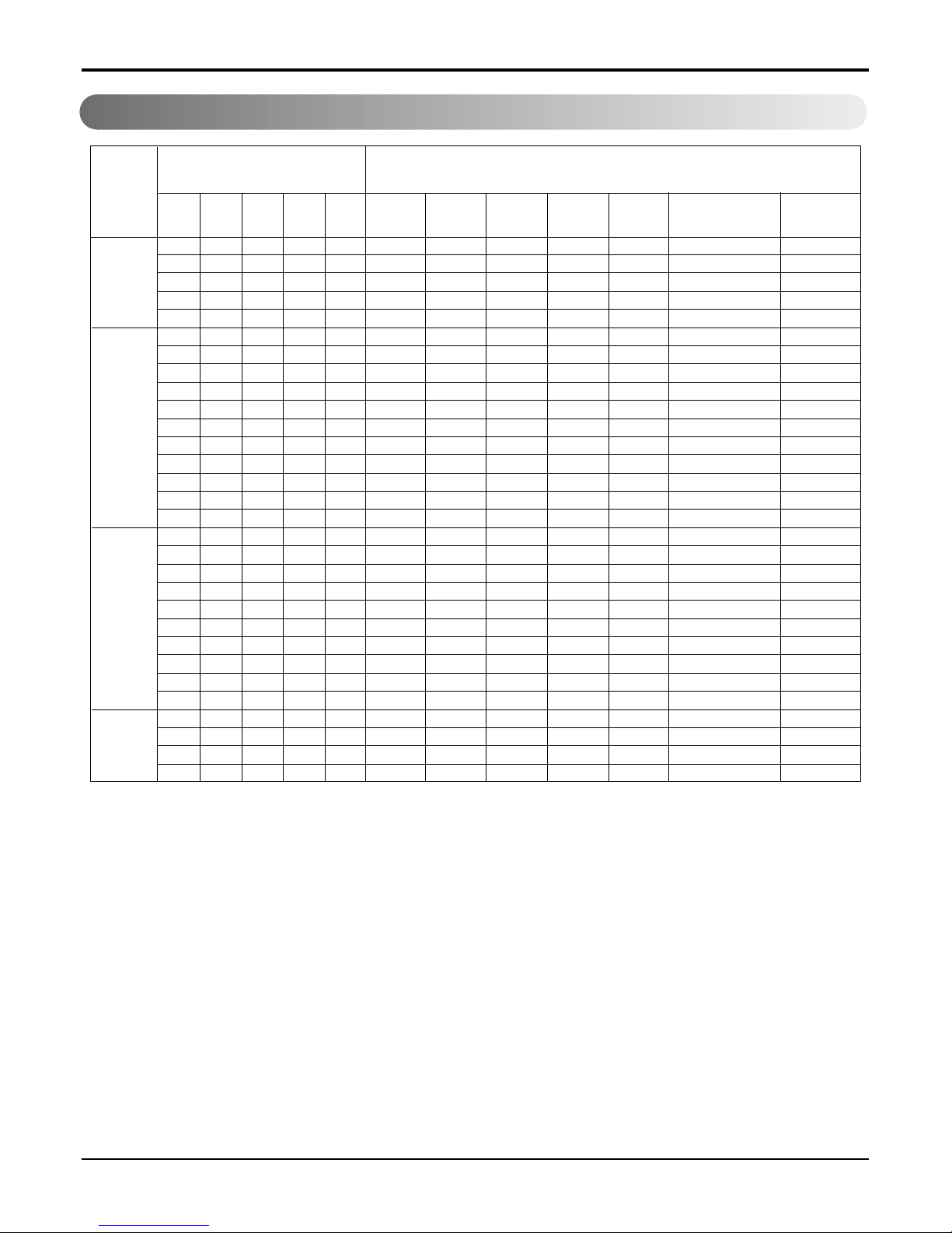
Combination Table
Combination Table
1. A2UH146FA0
2. A2UH186FA0
Cooling
Heating
Cooling
Heating
1 UNIT 7 7 9400 9400 1350 6.1 7
2 UNIT 7 7 14 7200 7200 14400 1450 6.6 9.9
Indoor Unit Combination
Index(k Btu/h)
Capacity
Input
(W)
Current
(A)
EER
(Btu/h.w)
Unit-A
(Btu/hr)
Unit-B
(Btu/hr)
Unit-C
(Btu/hr)
Unit-D
(Btu/hr)
Total
(Btu/hr)
ABCDTotal
Operation
1 UNIT 7 7 10000 10000 1500 7 6.7 2
2 UNIT 7 7 14 7300 7300 14600 1300 6 11.2 3.3
Indoor Unit Combination
Index(k Btu/h)
Capacity COP
Input
(W)
Current
(A)
(Btu/h.w) (w/w)
Unit-A
(Btu/hr)
Unit-B
(Btu/hr)
Unit-C
(Btu/hr)
Unit-D
(Btu/hr)
Total
(Btu/hr)
A B C D Total
Operation
7 7 7000 7000 780 3.5 9
1 UNIT 9 9 9500 9500 1100 5 8.6
12 12 11000 11000 1100 5 10
7 7 14 7000 7000 14000 1900 8.5 7.4
2 UNIT
7 9 16 7000 9000 16000 1900 8.5 8.4
9 9 18 9000 9000 18000 1900 8.5 9.5
7 12 19 7000 11000 18000 1900 8.5 9.5
Indoor Unit Combination
Index(k Btu/h)
Capacity
Input
(W)
Current
(A)
EER
(Btu/h.w)
Unit-A
(Btu/hr)
Unit-B
(Btu/hr)
Unit-C
(Btu/hr)
Unit-D
(Btu/hr)
Total
(Btu/hr)
A B C D Total
Operation
7 7 9000 9000 1300 6 6.9 2
1 UNIT 9 9 10500 10500 1250 5.6 8.4 2.5
12 12 12100 12100 1200 5.5 10.1 3
7 7 14 7700 7700 15400 1900 8.5 8.1 2.4
2 UNIT
7 9 16 7700 9900 17600 1900 8.5 9.3 2.7
9 9 18 9900 9900 19800 1900 8.5 10.4 3.1
7 12 19 7700 12100 19800 1900 8.5 10.4 3.1
Indoor Unit Combination
Index(k Btu/h)
Capacity COP
Input
(W)
Current
(A)
(Btu/h.w) (w/w)
Unit-A
(Btu/hr)
Unit-B
(Btu/hr)
Unit-C
(Btu/hr)
Unit-D
(Btu/hr)
Total
(Btu/hr)
A B C D Total
Operation
12 Free Joint Multi Air Conditioner
Combination Table
7 7 8000 8000 880 4 9.1
1 UNIT
9 9 9500 9500 900 4.1 10.6
12(Art) 12 11000 11000 1150 5.1 9.6
12 12 12000 12000 1150 5.1 10.4
7 7 14 8400 8400 16800 2100 9.4 8
7 9 16 8000 10000 18000 2100 9.4 8.6
2 UNIT
9 9 18 9500 9500 19000 2100 9.4 9
7 12(Art) 19 8000 11000 19000 2100 9.4 9
7 12 19 8000 12000 20000 2100 9.4 9.5
9 12 21 9000 12000 21000 2100 9.4 10
3 UNIT
7 7 7 21 7000 7000 7000 21000 2100 9.4 10
7 7 9 23 6400 6400 8200 21000 2100 9.4 10
Indoor Unit Combination
Index(k Btu/h)
Capacity
Input
(W)
Current
(A)
EER
(Btu/h.w)
Unit-A
(Btu/hr)
Unit-B
(Btu/hr)
Unit-C
(Btu/hr)
Unit-D
(Btu/hr)
Total
(Btu/hr)
A B C D Total
Operation
7 7 9000 9000 1350 6 6.7 2
1 UNIT
9 9 10450 10450 1350 6.2 7.7 2.3
12(Art) 12 12100 12100 1400 6.2 8.6 2.5
12 12 13200 13200 1400 6.2 9.4 2.8
7 7 14 9200 9200 18400 2200 9.8 8.4 2.5
7 9 16 8800 11000 19800 2200 9.8 9 2.6
2 UNIT
9 9 18 10000 10000 20000 2200 9.8 9.1 2.7
7 12(Art) 19 8800 12100 20900 2200 9.8 9.5 2.8
7 12 19 8400 12600 21000 2200 9.8 9.5 2.8
9 12 21 9000 12000 21000 1900 8.5 11.1 3.2
3 UNIT
7 7 7 21 7000 7000 7000 21000 1900 8.5 11.1 3.2
7 7 9 23 6400 6400 8200 21000 1900 8.5 11.1 3.2
Indoor Unit Combination
Index(k Btu/h)
Capacity COP
Input
(W)
Current
(A)
(Btu/h.w) (w/w)
Unit-A
(Btu/hr)
Unit-B
(Btu/hr)
Unit-C
(Btu/hr)
Unit-D
(Btu/hr)
Total
(Btu/hr)
A B C D Total
Operation
3. A3UH216FA0
Cooling
Heating
Service Manual 13
Combination Table
4. A4UH306FA0
7 7 9000 9000 1100 4.8
9 9 10000 10000 1130 5
1 Unit 12 12 12000 12000 1180 5.2
18 18 18000 18000 1900 9
24 24 23000 23000 3000 13.5
7 7 14 8000 8000 16000 1850 8.8
7 9 16 7500 9500 17000 1900 9
7 12 19 7000 12000 19000 1920 9.1
7 18 25 9000 19000 28000 3150 14.5
2 Unit
7 24 31 7000 22000 29000 3250 15
9 9 18 9000 9000 18000 1900 9
9 12 21 11000 14000 25000 3000 13.5
9 18 27 10000 18000 28000 3150 14.5
9 24 33 8000 21500 29500 3250 15
12 12 24 13000 13000 26000 3100 14
12 18 30 12000 18000 30000 3250 15
7 7 7 21 9000 9000 9000 27000 3150 14.5
7 7 9 23 9000 9000 11000 29000 3150 14.5
7 7 12 26 8000 8000 12000 28000 3250 15
7 7 18 32 6500 6500 17000 30000 3250 15
3 Unit
7 9 9 25 9000 10000 10000 29000 3250 14.5
7 9 12 28 7500 9500 12000 29000 3150 15
7 12 12 31 7000 11500 11500 30000 3250 15
9 9 9 27 10000 10000 10000 30000 3250 15
9 9 12 30 9000 9000 12000 30000 3250 15
9 12 12 33 8000 11000 11000 30000 3250 15
7 7 7 7 28 7500 7500 7500 7500 30000 3200 14.5
4 Unit
7 7 7 9 30 7000 7000 7000 9000 30000 3250 15
7 7 7 12 33 6500 6500 6500 10500 30000 3250 15
7 7 9 9 32 6500 6500 8500 8500 30000 3250 14.7
Combination (Indoor Unit) Cooling mode
Unit-A Unit-B Unit-C Unit-D
Total
(Btu/h)
ABCD
Total
(Btu/h)
Power
Consumtion(W)
Current(A)
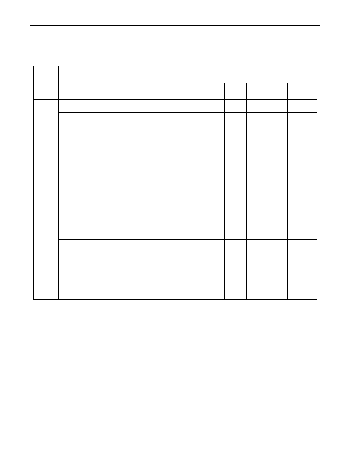
14 Free Joint Multi Air Conditioner
Combination Table
7 7 10000 10000 1350 6.2
9 9 11000 11000 1470 6.5
1 Unit 12 12 12000 12000 1310 6
18 18 18000 18000 2050 9.7
24 24 26400 26400 3600 16.5
7 7 14 8800 8800 17600 1950 9.3
7 9 16 8200 10300 18500 1950 9.3
7 12 19 7000 12000 19000 2050 9.7
7 18 25 9900 20900 30800 3360 15.5
7 24 31 7700 23000 30700 3300 15
2 Unit 9 9 18 9900 9900 19800 2050 9.5
9 12 21 12100 15400 27500 3360 15.5
9 18 27 11000 19800 30800 3360 15.5
9 24 33 8800 22500 31300 3360 15.5
12 12 24 14300 14300 28600 3360 15.5
12 18 30 13200 19800 33000 3360 15.5
7 7 7 21 9900 9900 9900 29700 3360 15.5
7 7 9 23 9900 9900 11000 30800 3400 15.5
7 7 12 26 8800 8800 13200 30800 3360 15.5
7 7 18 32 7100 7100 18700 32900 3360 15.5
3 Unit 7 9 9 25 9900 11000 11000 31900 3360 15.5
7 9 12 28 8200 10400 13200 31800 3360 15.5
7 12 12 31 7700 12600 12600 32900 3360 15.5
9 9 9 27 11000 11000 11000 33000 3360 15.5
9 9 12 30 9900 9900 13200 33000 3360 15.5
9 12 12 33 8800 12100 12100 33000 3360 15.5
7 7 7 7 28 8200 8200 8200 8200 32800 2950 13.5
4 Unit
7 7 7 9 30 7700 7700 7700 9900 33000 2950 13.5
7 7 7 12 33 7100 7100 7100 11700 33000 3000 14
7 7 9 9 32 7100 7100 9300 9300 32800 2950 13.5
Combination (Indoor Unit) Heating mode
Unit-A Unit-B Unit-C Unit-D
Total
(Btu/h)
ABCD
Total
(Btu/h)
Power
Consumtion(W)
Current(A)
Service Manual 15
Combination Table
5. A2UC146FA0
6. A2UC186FA0
7. A3UC216FA0
1 UNIT 7 7 10000 10000 1500 7 6.7
2 UNIT 7 7 14 7300 7300 14600 1300 6 11.2
Indoor Unit Combination
Index(k Btu/h)
Capacity
Input
(W)
Current
(A)
COP
(Btu/h.w)
Unit-A
(Btu/hr)
Unit-B
(Btu/hr)
Unit-C
(Btu/hr)
Unit-D
(Btu/hr)
Total
(Btu/hr)
A B C D Total
Operation
7 7 7000 7000 780 3.5 9
1 UNIT 9 9 9500 9500 1100 5 8.6
12 12 11000 11000 1100 5 10
7 7 14 7000 7000 14000 1900 8.5 7.4
2 UNIT
7 9 16 7000 9000 16000 1900 8.5 8.4
9 9 18 9000 9000 18000 1900 8.5 9.5
7 12 19 7000 11000 18000 1900 8.5 9.5
Indoor Unit Combination
Index(k Btu/h)
Capacity
Input
(W)
Current
(A)
COP
(Btu/h.w)
Unit-A
(Btu/hr)
Unit-B
(Btu/hr)
Unit-C
(Btu/hr)
Unit-D
(Btu/hr)
Total
(Btu/hr)
A B C D Total
Operation
Cooling
Cooling
Cooling
7 7 8000 8000 880 4 9.1
1 UNIT
9 9 9500 9500 900 4.1 10.6
12(Art) 12 11000 11000 1150 5.1 9.6
12 12 12000 12000 1150 5.1 10.4
7 7 14 8400 8400 16800 2100 9.4 8
7 9 16 8000 10000 18000 2100 9.4 8.6
2 UNIT
9 9 18 9500 9500 19000 2100 9.4 9
7 12(Art) 19 8000 11000 19000 2100 9.4 9
7 12 19 8000 12000 20000 2100 9.4 9.5
9 12 21 9000 12000 21000 2100 9.4 10
3 UNIT
7 7 7 21 7000 7000 7000 21000 2100 9.4 10
7 7 9 23 6400 6400 8200 21000 2100 9.4 10
Indoor Unit Combination
Index(k Btu/h)
Capacity
Input
(W)
Current
(A)
COP
(Btu/h.w)
Unit-A
(Btu/hr)
Unit-B
(Btu/hr)
Unit-C
(Btu/hr)
Unit-D
(Btu/hr)
Total
(Btu/hr)
A B C D Total
Operation
16 Free Joint Multi Air Conditioner
Combination Table
8. A4UC306FA0
7 7 9000 9000 1100 4.8 8.2
9 9 10000 10000 1130 5 8.8
1 UNIT 12 12 12000 12000 1180 5.2 10.2
18 18 18000 18000 1900 9 9.5
24 24 23000 23000 3000 13.5 7.7
7 7 14 8000 8000 16000 1850 8.8 8.6
7 9 16 7500 9500 17000 1900 9 8.9
7 12 19 7000 12000 19000 1920 9.1 9.9
7 18 25 9000 19000 28000 3150 14.5 8.9
7 24 31 7000 22000 29000 3250 15 8.9
2 UNIT 9 9 18 9000 9000 18000 1900 9 9.5
9 12 21 11000 14000 25000 3000 13.5 8.3
9 18 27 10000 18000 28000 3150 14.5 8.9
9 24 33 8000 21500 29500 3250 15 9.1
12 12 24 13000 13000 26000 3100 14 8.4
12 18 30 12000 18000 30000 3250 15 9.2
7 7 7 21 9000 9000 9000 27000 3150 14.5 8.6
7 7 9 23 9000 9000 11000 29000 3150 14.5 9.2
7 7 12 26 8000 8000 12000 28000 3250 15 8.6
7 7 18 32 6500 6500 17000 30000 3250 15 9.2
3 UNIT
7 9 9 25 9000 10000 10000 29000 3250 14.5 8.9
7 9 12 28 7500 9500 12000 29000 3150 15 9.2
7 12 12 31 7000 11500 11500 30000 3250 15 9.2
9 9 9 27 10000 10000 10000 30000 3250 15 9.2
9 9 12 30 9000 9000 12000 30000 3250 15 9.2
9 12 12 33 8000 11000 11000 30000 3250 15 9.2
7 7 7 7 28 7500 7500 7500 7500 30000 3200 14.5 9.4
4 UNIT
7 7 7 9 30 7000 7000 7000 9000 30000 3250 15 9.2
7 7 7 12 33 6500 6500 6500 10500 30000 3250 15 9.2
7 7 9 9 32 6500 6500 8500 8500 30000 3250 14.7 9.2
Indoor Unit Combination
Index(k Btu/h)
Capacity
Input
(W)
Current
(A)
COP
(Btu/h.w)
Unit-A
(Btu/hr)
Unit-B
(Btu/hr)
Unit-C
(Btu/hr)
Unit-D
(Btu/hr)
Total
(Btu/hr)
A B C D Total
Operation
Cooling
Service Manual 17
Dimensions
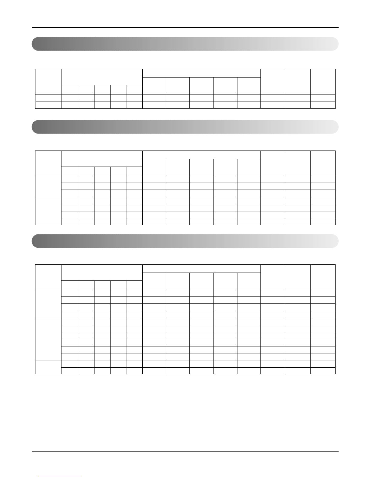
Dimensions
1. Indoor Unit
• Model: SQ/SR/ST chassis
Installation plate
D
H
W
Pipe Hole
Fix Hole
Hanger Hole
H
W
D
• Model: SP 1 chassis
Capacity W H D
SQ Ch. 7K/9K 824 260 156
SR Ch. 12K 900 285 156
ST Ch. 18K/24K 1080 314 182
Capacity W H D
SP1 Ch. 9K/12K 570 568 137
18 Free Joint Multi Air Conditioner
Dimensions
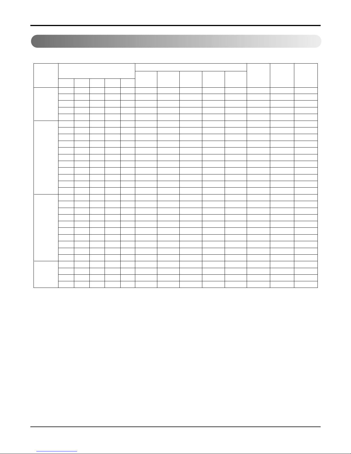
2. Outdoor Unit
W
L6L7 L8 L9
L4
H
D
L1
L2
L3
L5
L10
Gas side
3-way valve
Liquid side
2-way valve
L11L11L11
2-1 A2UC146FA0, A2UH146FA0
W mm 801
H mm 555
D mm 262
L1 mm 339
L2 mm 300
L3 mm 37
L4 mm 543.6
L5 mm 11.4
L6 mm 591
L7 mm 105
L8 mm 105
L9 mm 72.5
L10 mm 74.5
L11 mm 79
A2UC146FA0, A2UH146FA0
MODEL
DIM
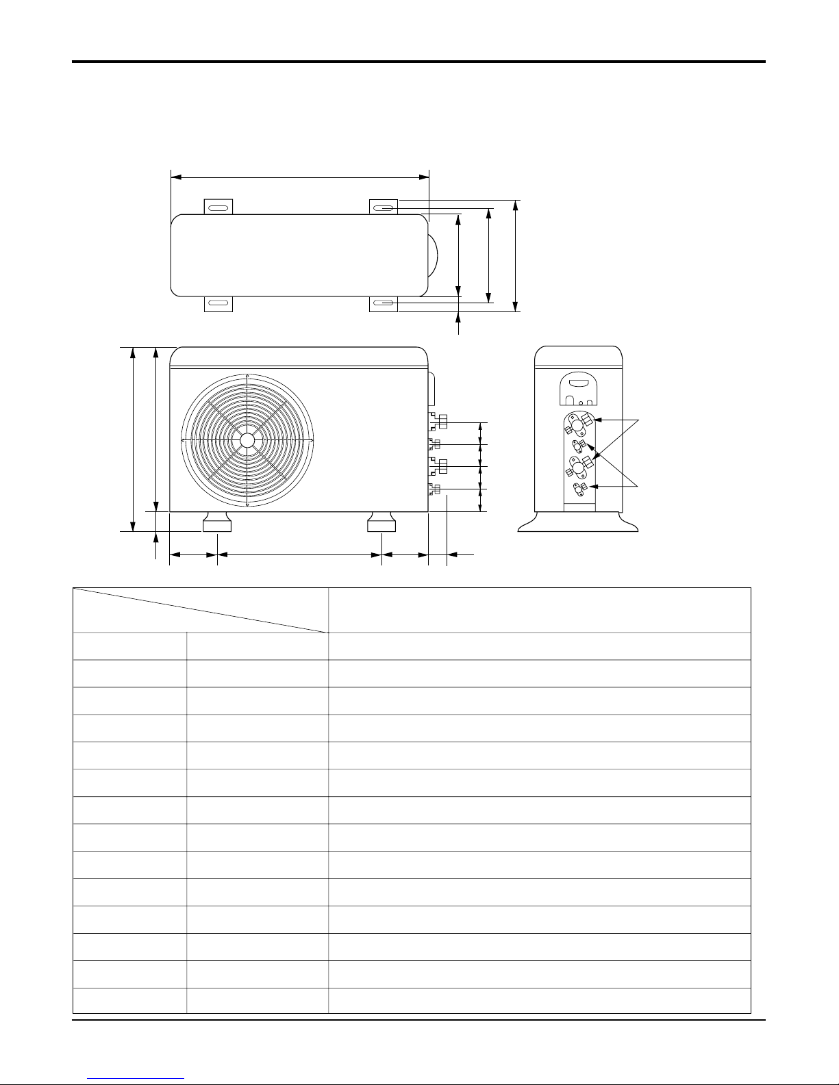
Service Manual 19
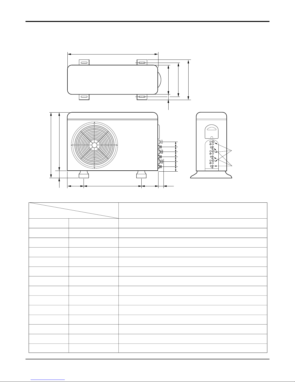
Dimensions
W
D
L1
L2
L3
L10
L5
L4
H
L11
L11
L11
L9
Gas side
3-Way valve
Liquid side
2-Way valve
L8L6L7
2-2. A2UC186FA0, A2UH186FA0
W mm 870
H mm 655
D mm 320
L1 mm 360
L2 mm 340
L3 mm 25
L4 mm 630
L5 mm 25
L6 mm 546
L7 mm 160
L8 mm 160
L9 mm 44
L10 mm 64.5
L11 mm 50
A2UC186FA0, A2UH186FA0
MODEL
DIM
20 Free Joint Multi Air Conditioner
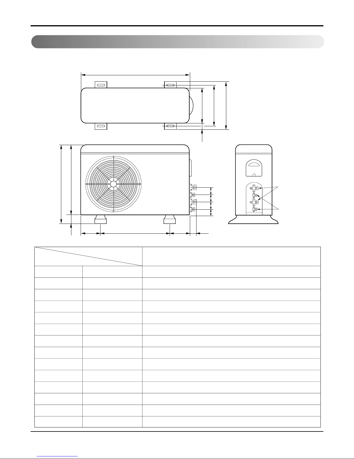
Dimensions
W
L6L7 L8 L9
L4
H
D
L1
L2
L3
L5
L10
Gas side
3-way valve
Liquid side
2-way valve
L11L11 L11L11L11
2-3 A3UC216FA0, A3UH216FA0
W mm 870
H mm 655
D mm 320
L1 mm 360
L2 mm 340
L3 mm 25
L4 mm 630
L5 mm 25
L6 mm 546
L7 mm 160
L8 mm 160
L9 mm 44
L10 mm 64.5
L11 mm 50
A3UC216FA0, A3UH216FA0
MODEL
DIM
Service Manual 21
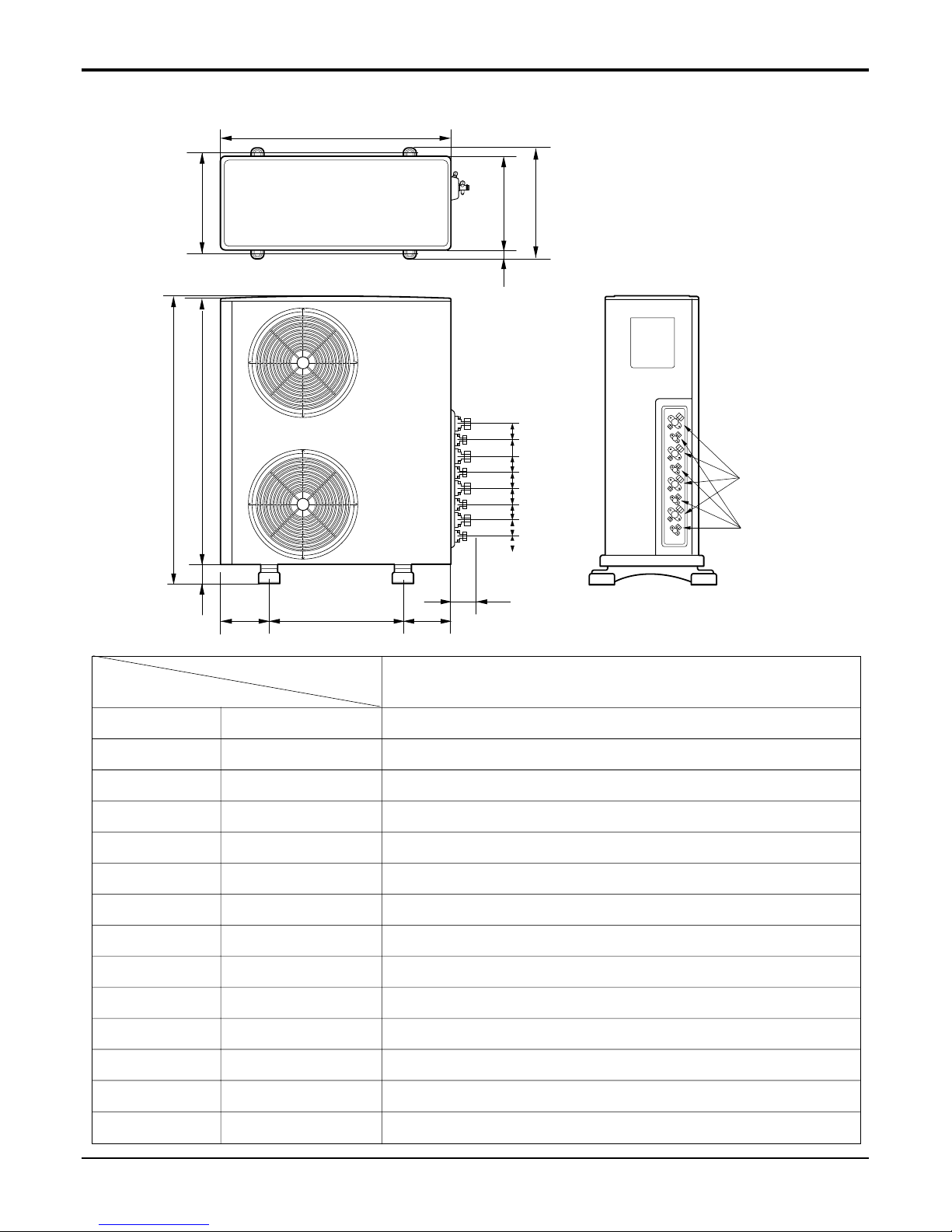
Dimensions
L6L7 L8
L9
L4
H
L5
W
D
L1
L3
L2
L10 L11 L11 L11 L11 L11L11L11
Gas side
3-way valve
Liquid side
2-way valve
2-4 A4UC306FA0, A4UH306FA0
W mm 870
H mm 1038
D mm 320
L1 mm 360
L2 mm 340
L3 mm 25
L4 mm 1035
L5 mm 25
L6 mm 546
L7 mm 160
L8 mm 160
L9 mm 44
L10 mm 64.5
L11 mm 50
A4UC306FA0, A4UH306FA0
MODEL
DIM
22 Free Joint Multi Air Conditioner
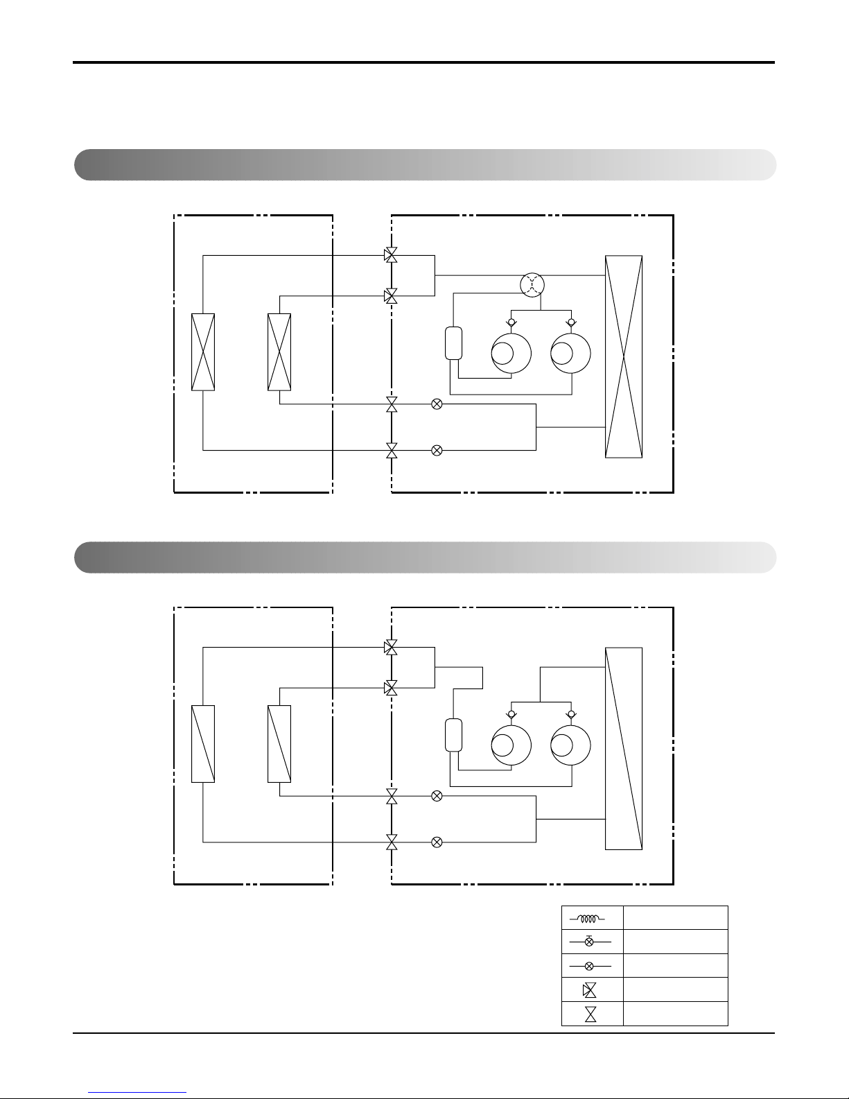
Refrigeration Cycle Diagram
Indoor Side Outdoor Side
A
B
4- WAY Valve
COMP
Indoor Side Outdoor Side
A
B
COMP
ex)
Solenoid Valve
L.E.V
3-Way Valve
2-Way Valve
Capillary
Refrigeration Cycle Diagram
1. A2UH146FA0
2. A2UC146FA0
Service Manual 23
Refrigeration Cycle Diagram
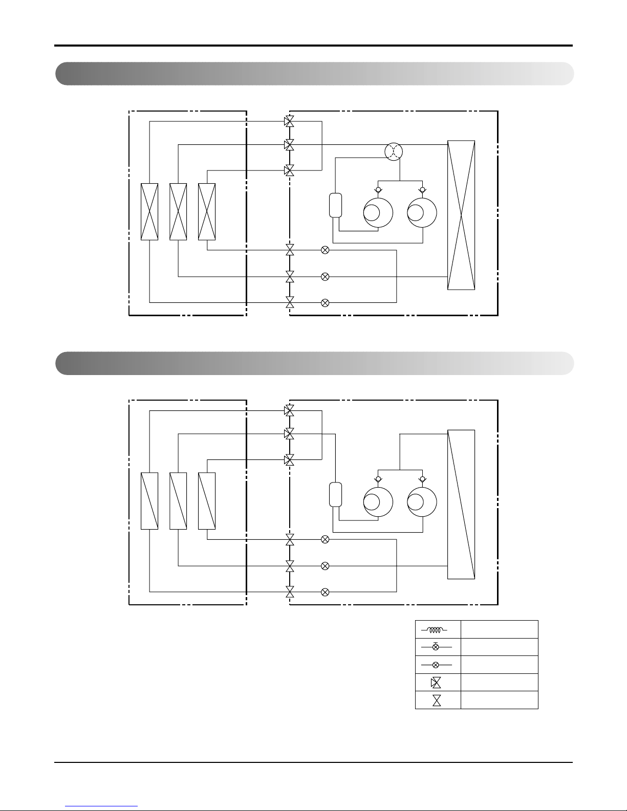
3. A2UH186FA0
4. A2UC186FA0
Indoor Side Outdoor Side
A
B
4- WAYValve
COMP B
COMP A
Indoor Side Outdoor Side
A
B
COMP B
COMP A
ex)
Solenoid Valve
L.E.V
3-Way Valve
2-Way Valve
Capillary
Accum.Accum.
24 Free Joint Multi Air Conditioner
Refrigeration Cycle Diagram
5. A3UH216FA0
6. A3UC216FA0
Indoor Side Outdoor Side
B
A
4- WAY Valve
COMP B
COMP A
Accum.
C
Indoor Side Outdoor Side
B
A
COMP B
COMP A
Accum.
C
ex)
Solenoid Valve
L.E.V
3-Way Valve
2-Way Valve
Capillary
 Loading...