

Page 1

INSTALLATION MANUAL
LG Digital Signage
(MONITOR SIGNAGE)
Please read this manual carefully before operating your set and
retain it for future reference.
60UL3E
70UL3E
www.lg.com
Copyright © 2018 LG Electronics Inc. All Rights Reserved.
Page 2

Table of contents
ENGLISH
3 Location and Function of Controls
3 Parts and Button
3 Basic functions
4 First Use Wizard
4 Language & Location
5 Installation Menu
5 Introduction
6 Public Display Settings
6 - Public Display Settings
6 - Power On Status
7 - Volume
7 - Key Management
8 - Limited Mode
9 - Power On Default
9 - Aux Source Setting
9 - Power Management
9 - Factory Reset
10 Network
10 - MAC Address
10 - Network Setting
11 - Wake On LAN
11 - Server Setting
12 General
12 - Configuration Setup
14 - Set ID Setup
14 - Power Saving
15 - HCEC Setup
16 - Clock Setup
16 - Password Change
16 - Lock Mode
16 - Crestron
17 Signage Manager
24 - USB Download Menu
25 KEY CODES
26 EXTERNAL CONTROL DEVICE SETUP
26 RS-232C Setup
26 USB to Serial converter with USB Cable
26 RS-232C with RS-232C Cable
27 Set ID
28 Communication Parameters
28 Command reference list
29 TRANSMISSION / RECEIVING
PROTOCOL
2
Page 3
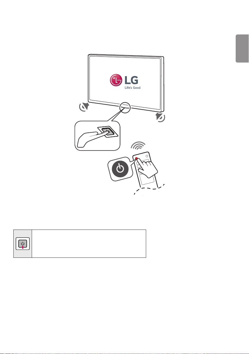
Location and Function of Controls
Parts and Button
ENGLISH
Basic functions
Power On (Press)
Power O1 (Press and Hold)
Menu Control (Press2)
Menu Selection (Press and Hold3)
1 All running apps will close.
2 You can access and adjust the menu by pressing the button when Signage is on.
3 You can use the function when you access menu control.
3
Page 4
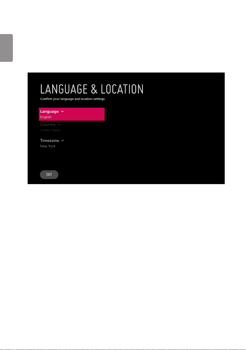
First Use Wizard
* Image shown may differ from your Signage.
ENGLISH
Language & Location
(Depending upon model)
• Select the Language and Country. Some countries need to select the Time Zone.
4
Page 5

Installation Menu
* Image shown may differ from your Signage.
Introduction
The abundant functions for Signage linked with software installation can be projected on OSD as ‘Installation
Menu’.
The wide range of features can be performed simply on additional window to enhance the Signage’s easy
installation and convenient operation for System Integrators.
1 Press the Setting button for more than 5 seconds using the user remote control, banner will appear at top left
on the screen.
2 Enter a four digit password and press button.
- The initial password “1-1-0-5”.
ENGLISH
5
Page 6

Public Display Settings
ENGLISH
When ‘Public Display Settings’ is set to On (Work), all functions of Public Display Mode apply.
Public Display Settings
• Decide to work all functions of ‘Public Display Settings’ or not by setting ‘Public Display Settings’ as On ( Work)
or O (Do Not Work).
• When ‘Public Display Settings’ is set to On ( Work), all functions of Public Display Mode apply.
• When ‘Public Display Settings’ is set to O (Do Not Work), all functions of Public Display Mode Do Not apply.
• When it is set to ‘On’, all items reserved at the Schedule list are deleted and the reservation function is not
supported. (applied for the model oering the reservation function)
Power On Status
• Decide to select working status of Signage Set when turn on main power.
• You can set with PWR, STD, LST.
• PWR always make Signage set On status when turn on main power.
• STD make Stand-by status when turn on main power.
• LST make Signage Set work like previous power status. As same concept as Power Backup mode; If main power
were turned o in Power On status, Signage Set would work in On status. If main power were turned o in
Stand-by status, Signage Set would work in Stand-by status.
• If there Block All is both IR Operation and Local Key Operation from Key Management, In order to provide the
Option that must be able to turn on the Signage in the Signage turned o situation, change the value of the
PWR. (Reference the Key Management)
6
Page 7

Volume
• Decide to apply volume policy of ‘Start Volume’, ‘Maximum Volume’ and ‘Minimum Volume’ as On (Work) or O
(Do Not Work).
• (0 ≤ Min ≤ Start ≤ Max ≤ 100)
Start Volume
• This entry sets the start volume level when is power on.
-The level is specified as a number between minimum volume to maximum value. (Min ≤ Start ≤ Max)
-The default setting is ‘Off’ (disabled).
-When enabled, if the value is lower than the minimum specified in the minimum volume entry, the
minimum volume entry must be used.
-When enabled, if the value is larger than the maximum specified in the maximum volume entry, the
maximum volume value must be used.
Maximum Volume
• This entry sets the maximum volume level the set. The level is specied as a number between ‘Minimum
Volume’ to 100. (Min ≤ Max ≤ 100).
-If the command volume up to higher than maximum volume’ is received, that should be ignored.
-The default value is 100.
Minimum Volume
• This entry sets the minimum volume level the set will produce.
-The level is specified as a number between 0 to ‘Maximum Volume’. (0 ≤ Min ≤ Max)
-If the command volume down to lower than minimum volume is received, that should be ignored.
-The default value is 0.
Key Management
• Manage key usability of Local(Front) Key and Remote Control. When selected to ‘On’, following ‘IR Operation’
and ‘Local Key Operation’ will be worked by below.
ENGLISH
IR Operation
• Decide whether work the LG remote control or not.
-When ‘IR Operation’ is set to 'Normal', all remote keys are available.
-'Use PWR Only' makes block all remote keys except power key.
-When ‘IR Operation’ is set to 'Block All', all normal remote keys don’t work.
Local Key Operation
• Decide to operate 'Local/Front Key' working behavior by setting ‘Local Key Operation’ as 'Normal', 'Use PWR
Only' and 'Block All'.
-When ‘Local Key Operation’ is set to 'Normal', all local keys are available.
-'Use PWR Only' makes block all local keys except power key.
-When ‘Local Key Operation’ is set to 'Block All', all local keys don’t work.
7
Page 8

Limited Mode
• Congure Signage function’s limitation. When selected to ‘On’, following sub-menus will be worked by below.
Menu Display
ENGLISH
• Function to decide whether work with menu (including relevant menus too) of control key (On – Enter
OSD Display
• Decide to display OSD or not by setting ‘OSD Display’ as On (Display) or O (Do not Display).
System Provider Mode
• ‘System Provider Mode’ allows access to the menu system from the front panel or remote control but access is
possible) or not (O – Enter Impossible).
-Although select Off (Enter impossible), the action that press a Menu button for 5 seconds to enter
‘Installation Menu’ is available.
-When select On (Enter possible), Menu works.
-When ‘OSD Display’ is set to ‘Off ’(Do not Display), all OSD is not displayed except some exception.
-Although select ‘Off’ (Do not Display), the action that press a Menu button for 5 seconds to enter
‘Installation Menu’ and entering service menu are available. (In-Start, Power-Only, Adjust, Installation
Menu...)
controlled as follows:
-When value is ‘On’, Accessible Items on the menu system, others are not permissible. (Depending upon
model)
» Input select screens
» Sleep timer
» Aspect Ratio
» 'Photo & Video' / Music' / ‘Network’ / ‘Bluetooth’ Menu.
» Input Manager
8
Page 9

Power On Default
• Set to On ( Work) or O (Do Not Work).
• When ‘Power On Default’ is set to O, it is not applied to the subordinate Input, A/V Setting, Aspect Ratio
menu.
• When Power On Default is set to On, it can set by entering the subordinate menu.
Input
• Set whether it is turned on by the set input source or by the last stored input source.
A/V Setting
• If ‘A/V Setting’ is changed from ‘O’ to ‘On’, A/V parameters that are set before entering ‘Installation Menu’ are
applied whenever turn on power.
Aspect Ratio
• The aspect ratio determines the default aspect ratio that the set returns to on power up.
Aux Source Setting
• Set to On ( Work) or O (Do Not Work).
• The Auxiliary (Input) Source Setting feature will enable or disable for each external input.
• User cannot disable the current input’s ‘Aux Source Setting’.
Power Management
• The Power Management feature will turn o the Signage if no input control command is received from either
the Local or IR Key within selected hours.
-Activity on either of these inputs shall reset the ‘Power Management’ timer and prevent interruption of
Signage viewing.
-This entry can be set to a value which is corresponding to the desired hours (1 hour to 7 hours).
-Default value is ‘Off (disabled)’.
ENGLISH
Factory Reset
• Change all settings to their default values.
9
Page 10
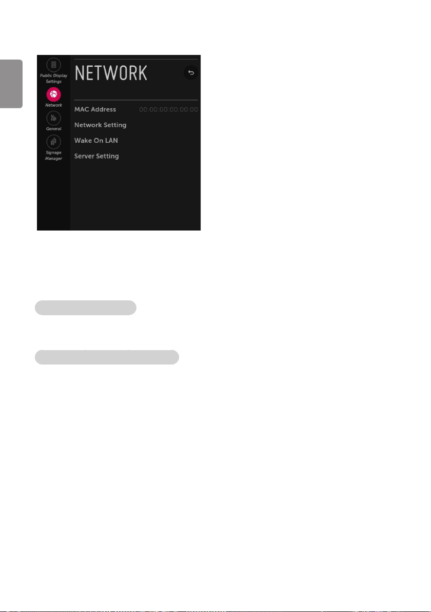
Network
ENGLISH
MAC Address
• Displays the MAC address (not customizable).
Network Setting
One-click network connection
• Connects easily to a wired network.
• This menu supports to connect to an available network.
To connect to a network through Set Expert
• For use in special circumstances such as in oces (in cases where a static IP is used).
1 Select a network connection.
2 When connecting via Wired, Congures the IP settings of the Signage set. You can set the IP address,
subnet mask, gateway and DNS server.
10
Page 11

Wake On LAN
• Sets the Wake On LAN function to Enable or Disable.
-The Wake On LAN feature enables the Signage to receive software updates and/or be powered ON upon
receipt of Wake Up Frame packets and/or Magic Packet data via the wired LAN. To facilitate use of this
feature, note that the appropriate wired connection must be made. (‘Wake up Frame’ - Depending upon
model)
Server Setting
(Depending upon model)
• Sets the information to connect to the external server.
CMS Server
• Sets the network information to connect to SuperSign CMS. (or other compatible solutions)
Control Server
• Sets the network information to connect to SuperSign Control. (or other compatible solutions)
ENGLISH
11
Page 12
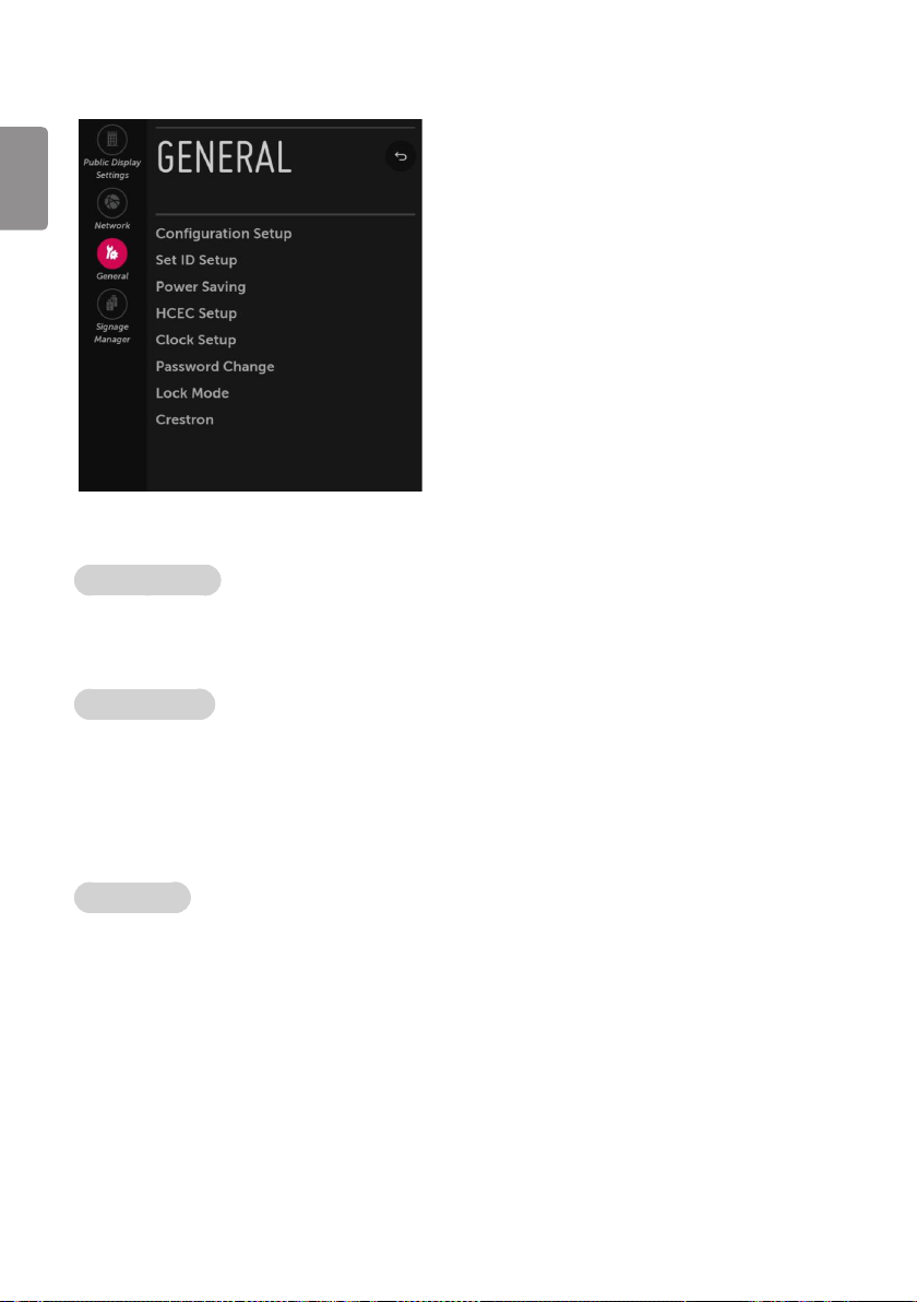
General
ENGLISH
Conguration Setup
On Timer Operation
• It is a mode to select ‘Timer Power On’ working one time or repeatedly.
• 'Once': ‘Timer Power On’ in the user menu operates only one time when the Timer Power On menu is set to On.
• ‘Repeat’ : ‘Timer Power On’ operates repeatedly when the Timer Power On menu is set to On.
USB Auto Playback
(Depending upon model)
• When ‘USB Auto Playback’ is set to ‘Movie’, Signage nds and plays the USB’s movie les located at the root(top)
directory Movies if USB is plugged in.
• When ‘USB Auto Playback’ is set to ‘Photo’, Signage nds and plays the USB’s photo les located at the root(top)
directory Photos if USB is plugged in.
• If it reaches the last le, it starts the rst le again.
15Min Auto Off
(Depending upon model)
• When ‘15Min Auto O’ is set to ‘Enable’, TV will turn o if there is no signal in 15Min.
12
Page 13

Auto Sensing
• If ‘Auto Sensing’ is set to ‘On’, the input is automatically switched when the input signal that you set to “ON’ is
received.
• If ‘Auto Sensing’ is set to ‘Disable’, the input is not switched when the input signal is received.
-SIMPLINK and Auto Sensing cannot work simultaneously. If SIMPLINK is set to On, Auto Sensing is
automatically set to Disable.
-If the signal is removed while Auto Sensing (automatic input switch) is enabled, the input returns to the
previous setting.
If the several input are connected by enabling Auto Sensing and the automatic input returns to the
previous setting.
If the several inputs are connected by enabling Auto Sensing and the automatic input switch is
performed several times, the input returns to the previous setting only for the last input and does not
repeat the operation for the rest.
DPM
(Depending upon model)
• You can congure the DPM (Display Power Management) function.
• If this option is not set to O, the Signage set enters the DPM mode when there is no input signal.
• If you set this option to O, the DPM function is disabled.
Sustain Aspect Ratio
(Depending upon model)
• Sustain Aspect Ratio sets the power mode of the HDMI Switching IC, which detects HDMI external input
signals in the Signage Standby state after DPM Power O turns o the Signage.
• If Sustain Aspect Ratio is set to ON, the HDMI Switching IC is supplied with power even in Standby state after
DPM turns o the Signage.
• If Sustain Aspect Ratio is set to OFF, the HDMI Switching IC maintains low power mode in Standby state after
DPM turns o the Signage.
Screen Saver
• When the currently displayed app has not received any user input for an hour, it will be replaced by a Screen
Saver.
• If you turn this option ‘O’, the current picture may create an afterimage burned onto your screen, possibly
permanently.
ENGLISH
13
Page 14

ENGLISH
Set ID Setup
Set ID Lock
• Set the ‘Set ID’ item in GENERAL Menu whether to activate or not.
• Set to On ( Work) or O (Do Not Work).
Set ID
• Set the ‘Set ID’ of Signage Set with 1~99.
Power Saving
Static Saving
• It is the item for setting the level to reduce the backlight control from the items for saving the consuming
power, which is increased or decreased by 10 steps from 0 to 100. 100 makes the consuming power set to the
same one from the Signage. 0 reduces the consuming power to the minimum. The default value is 100.
-The value displayed at the OSD is not changed and only the actual setting value is converted to
percentage based on the static saving value to set.
-0 ~ 30: HIGH, 40 ~ 60 : MID, 70 ~ 90 : LOW, 100 : OFF.
Keyless Off Hours
• Automatically Signage will be turned o if there is no key input for the preset time period.
14
Page 15
HCEC Setup
CEC Mode
(Depending upon model)
• You will have 2 modes to choose [Default], [HCEC].
• If [Default] is selected, you can use SIMPLINK which is provided in LG Signage. Also you can enable and disable
SIMPLINK through SIMPLINK MENU.
IR Decoding
• When ‘IR Decoding’ is set to ‘Enable’, the Signage decodes and changes it into a CEC Message and sends it to
Command via the HDMI CEC Line. The default value is Disable.
Device ID
• Sets the ID of a device(Logical Address) connected to the CEC Line. You can choose ‘All’ and from ‘0 x 01’ to ‘0 x
0E’(All, 0 x 01 ~ 0 x 0e).
• The default value is ‘All’.
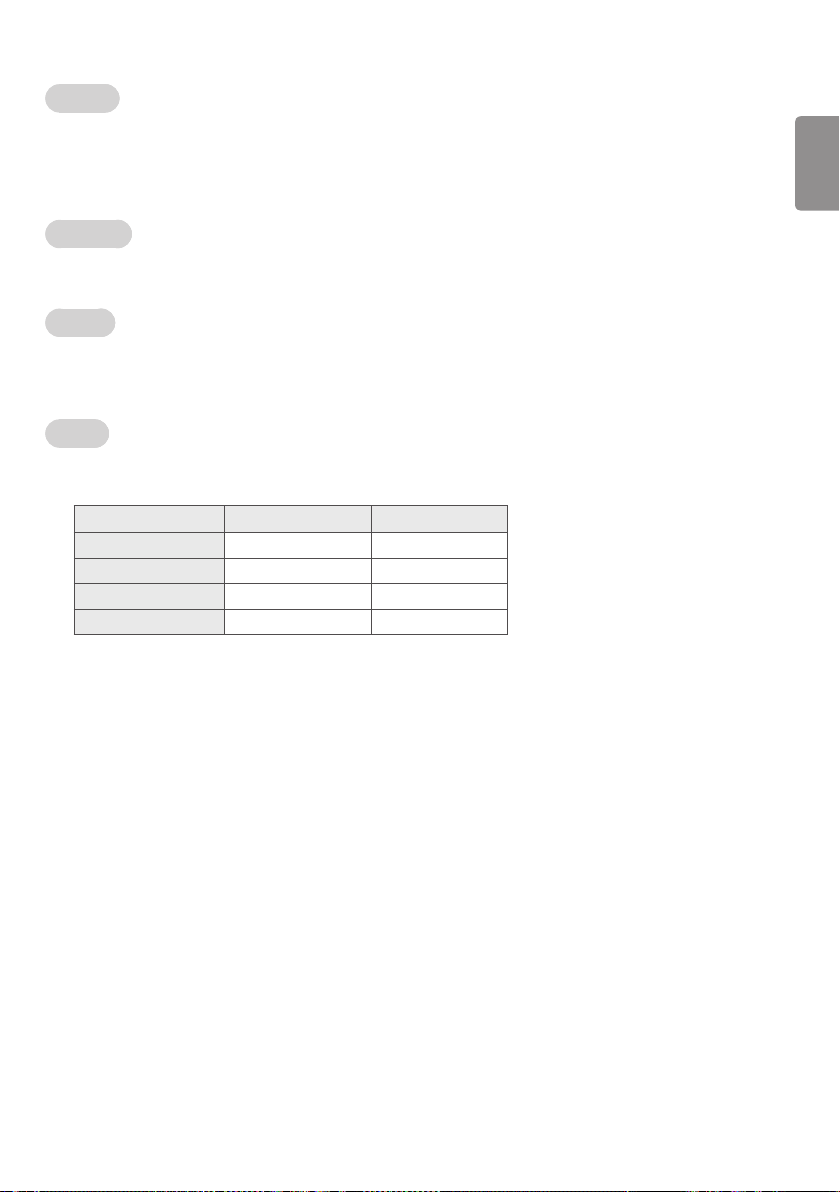
StandBy
• Set the sending and receiving scenario of OpStandBy(0 x 0c) command.
• This detailed scenario is described on the table below.
Send Receive
Send Only O X
Receive Only X O
All O O
O X X
ENGLISH
15
Page 16

Clock Setup
Clock Source
ENGLISH
• You can select ‘O ’, ‘NTP’, ‘Admin’.
• NTP : Clock is synchronized using Network Time Protocol. It's only enabled when network cable is connected.
• Admin : It's automatically set to Admin when clock is updated by commercial protocols like TVLink-HCEC.
• O : Clock is synchronized using any available clock source.
-Input (Depending upon model)
» You can select 'Input' according to 'Clock Source'.
» Input is set to 'None', 'HCAP', 'Protocol', 'HTNG' automatically when Clock Source is 'Admin'.
Password Change
• To ensure more security, Password can be changed by installers’ own design.
1 Change password by using virtual keyboard.
2 Input the password again for conrmation.
Lock Mode
• If ‘Lock Mode’ is ‘Yes’, the following features will be unavailable.
USB
• If it is set to ‘Enable’, USB devices do not work in relative features. (Exclude S/W update)
Factory Reset
• If it is set to ‘Enable’, User Menu General Reset to Initial Settings is disabled.
Crestron
(Depending upon model)
• This function enables synchronization with applications provided by Crestron.
• Server: This menu sets the server’s IP address for the network connection with the server. (equipment provided
by Crestron)
• Port (1024~65535): This menu sets the port for the network connection with the server. The default port
number is 41794.
• IP ID (3-254): This menu sets a unique ID for synchronizing with the application.
16
Page 17
Signage Manager
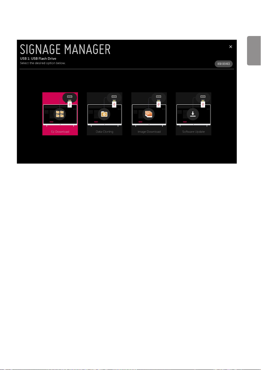
You can update les from USB to Signage through the Signage manager.
ENGLISH
17
Page 18
ENGLISH
Ez Download
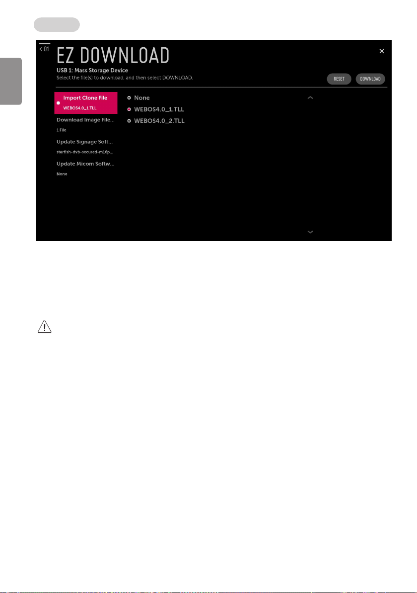
• Ez Download is a function that enables users to download the desired items all at once, such as EPK (software
update le), TLL, Image, Micom.
-Images and Software Update files should be copied into the folder named LG_DTV on the USB.
» TLL files should be copied to the root folder of the USB.
» If you press ‘EZ Download’ menu, EZ Download is launched.
» If ".DZM" file exist file will be selected previously download file.
18
• DZM le is created in USB after the download is complete.
If USB containing “DZM” is connected after Signage is turned on, Signage Manager will be automatically
launched. Then, EZ Download is displayed and previously downloaded les are selected automatically.
Page 19
Export Clone File
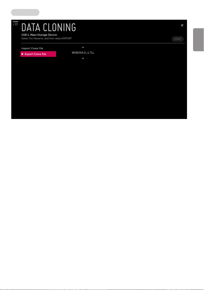
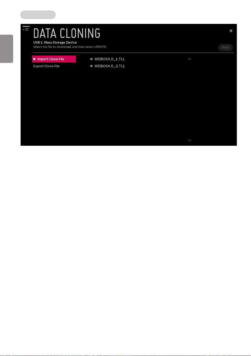
• “Export Clone File” creates “TLL” le in USB root folder. “ TLL” le can be used to “Import Clone File”. While
writing is in process, the user must not turn Signage o nor unplug the USB memory card. The following
reference images might be slightly dierent.
ENGLISH
19
Page 20
ENGLISH
Import Clone File
• Once the internal Signage data is written to the USB memory card, the user can start “Import Clone File”
process with the data le generated and stored in USB memory card. The user should not turn Signage o nor
unplug the USB memory card while processing. The following reference images might be slightly dierent.
20
Page 21
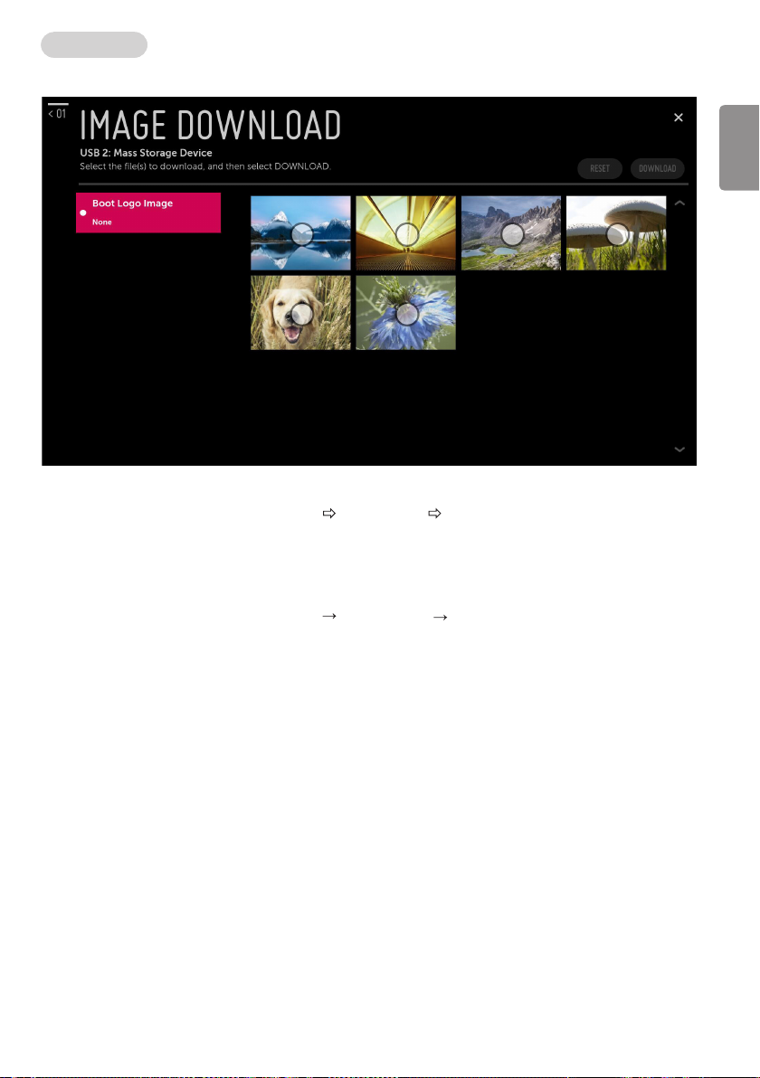
Image Download
* Image shown may differ from your Signage.
• If there are more than two USB Memory Device, It is possible to select the USB.
• The download sequence is Image Download Select Image(s) Download.
• Image les should be in “LG_DTV” folder.
-Boot Logo Image
» Boot Logo Image can download only one file.
» Boot Logo Image update function supports only JPG, JPEG, BMP format file of less than 8 MB file size.
» We recommend you that splash image resolution match the Signage`s panel resolution.
» Max resolution of splash image : Full HD 1920 x 1080, HD 1360 x 768.
» Min resolution of splash image : 64 x 64.
ENGLISH
21
Page 22
ENGLISH
Software Update
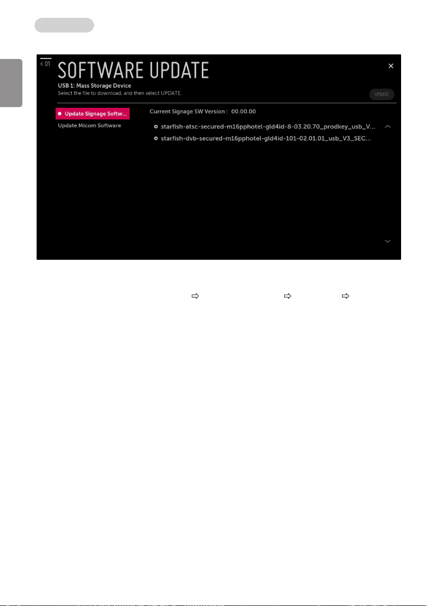
► Update Signage Software
• This feature updates Signage software through the EPK le in USB.
• “.EPK” les should be in “LG_DTV” folder.
• The download sequence is Software Update Update Signage Software Select le(EPK) UPDATE.
22
Page 23
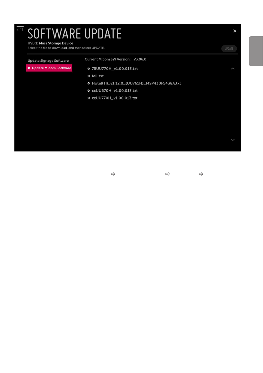
► Update Micom Software
• This feature updates Micom software through the txt le in USB.
• “.txt” les should be in “LG_DTV” folder.
• The download sequence is Software Update Update Micom Software Select le(txt) UPDATE.
ENGLISH
23
Page 24

USB Download Menu
USB Cloning
ENGLISH
• An Installer can quickly set up and clone multiple Signage sets at a property. These cloned Signages will all
have the same Master Signage Setup: Public Display Mode Installation Menu settings, User A/V settings. This
newer procedure signicantly decreases the installation time that would be necessary if the standard RS-232C
method were used instead.
1 Overview USB Cloning Procedure
2 Data To Be Cloned
: Signage has the capability to support cloning internal Signage data with an external clone device called
“USB Cloning”, in order to copy Signage data accurately and quickly. The clone internal functions use
a slightly dierent internal processes for the two types of signage. However, the UI of cloning feature
remains the same in both. Regarding the demands over the current cloning feature for quicker cloning,
better portability and etc., we would like to announce the cloning process via USB port, named as USB
Cloning. USB cloning process is divided into 2 main processes. One is writing the previously saved Signage
data into the Signage, and one another is reading of current Signage data into USB memory card. To avoid
any confusion due to the words, it is clearly specied as “Import Clone File” and “Export Clone File” in the
whole process.
: The data cloned are the same data cloned by previous USB Cloning. Details are explained in the following:
-Signage data includes :
A. Installer Menu settings
B. Main menu settings (Audio, Picture etc)
24
Page 25
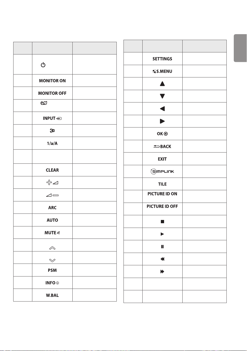
KEY CODES
• This feature is not available for all models.
Code
(Hex)
08
C4
C5
95
0B
DC
32
10-19
2F
02
03
79
99
09
E0
E1
4D
AA
5F
Function Note
Remote control
(POWER)
ENERGY
SAVING
Number Key 0-9
Alphabet buttons
Brightness (PAGE) Remote control
Brightness (PAGE) Remote control
Button
(Power On/O)
Remote control
Button
Remote control
Button
Remote control
Button
Remote control
Button
Remote control
Button
Remote control
Button
Remote control
Button
Remote control
Button
Remote control
Button
Remote control
Button
Remote control
Button
Remote control
Button
Remote control
Button
Button
Button
Remote control
Button
Remote control
Button
Remote control
Button
Code
(Hex)
43
3F
40
41
07
06
44
28
5B
7E
7B
72
71
B1
B0
BA
8F
8E
63 Yellow
61 Blue
Function Note
(Red)
(Green)
ENGLISH
Remote control
Button
Remote control
Button
Remote control
Button
Remote control
Button
Remote control
Button
Remote control
Button
Remote control
Button
Remote control
Button
Remote control
Button
Remote control
Button
Remote control
Button
Remote control
Button
Remote control
Button
Remote control
Button
Remote control
Button
Remote control
Button
Remote control
Button
Remote control
Button
Remote control
Button
Remote control
Button
• Key code 4C (0 x 4C) is available on ATSC/ISDB models which use major/minor channel. (For South Korea, Japan,
North America, Latin America except Colombia models)
25
Page 26
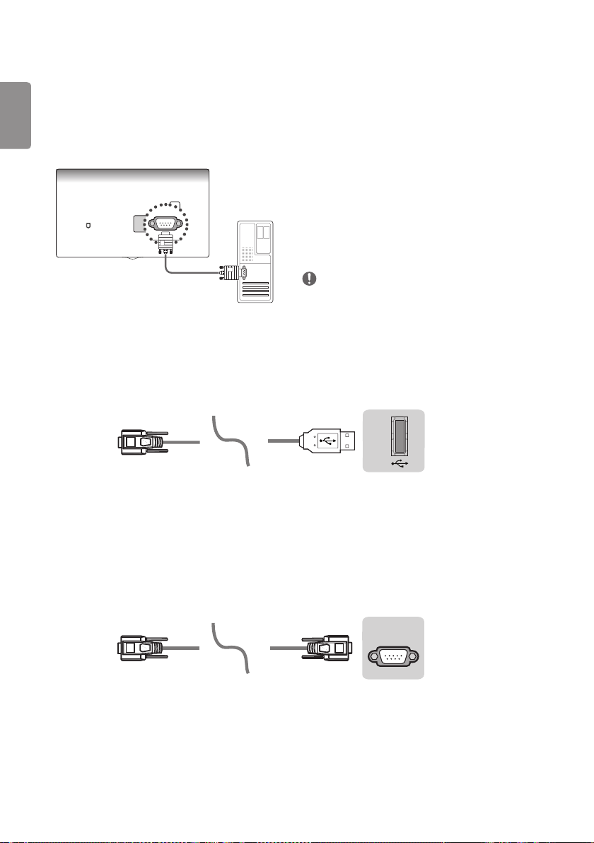
EXTERNAL CONTROL DEVICE SETUP
(PC
USB IN
(TV)
(PC)
* Image shown may differ from your signage.
ENGLISH
* Cable is not provided.
* The connection interface may differ from your Signage.
RS-232C Setup
USB to Serial converter with USB Cable
USB Type
)
• Connect the USB to Serial converter/RS-232C input
jack to an external control device (such as a computer
or an A/V control system) to control the product’s
functions externally.
• Connect the serial port of the control device to the
RS-232C jack on the product back panel.
NOTE
• The type of control port on the signage can be
dierent between model series.
(TV)
USB IN
(Signage)
• LG signage supports PL2303 chip-based ( Vendor ID : 0 x 0557, Product ID : 0 x 2008) USB to serial converter
which is not made nor provided by LG.
• It can be purchased from computer stores that carry accessories for IT support professionals.
RS-232C with RS-232C Cable
DE9 (D-Sub 9pin) Type
RS-232C IN
(PC)
(CONTROL & SERVICE)
• You need to purchase the RS-232C (DE9, D-Sub 9 pin female-to-female type) to RS-232C cable required for the
connection between the PC and the signage, which is specied in the manual.
• The connection interface may dier from your signage.
26
(Signage)
(TV)
Page 27
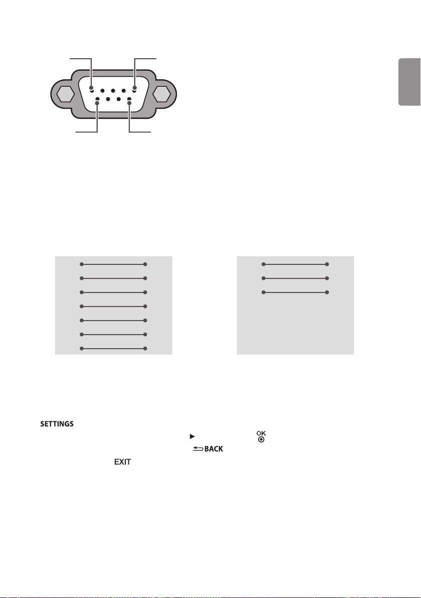
Connector type : D-Sub 9-pin male
1
6
RS-232C
(Serial port)
RS-232C congurations
7-Wire Congurations
(Standard RS-232C cable)
PC Signage
RXD 2 3 TXD
TXD 3 2 RXD
GND 5 5 GND
DTR 4 6 DTR
DSR 6 4 DSR
RTS 7 8 RTS
CTS 8 7 CTS
D-Sub 9 D-Sub 9
5
9
ENGLISH
3-Wire Congurations
(Not standard)
PC Signage
RXD 2 3 TXD
TXD 3 2 RXD
GND 5 5 GND
DTR 4 6 DTR
DSR 6 4 DSR
RTS 7 8 RTS
CTS 8 7 CTS
D-Sub 9 D-Sub 9
Set ID
For Set ID number, see “Real data mapping (Hexadecimal : Decimal)”.
Press to access the main menus.
Press the Navigation buttons to scroll to (* [General] [Set ID]) and press .
Scroll left or right to select a set ID number and select . The adjustment range is 1-99.
When you are nished, press .
27
Page 28
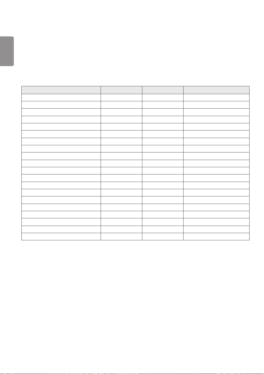
Communication Parameters
• Baud rate : 9600 bps (UART)
ENGLISH
• Data length : 8 bits
• Parity : None
• Stop bit : 1 bit
• Communication code : ASCII code
• Use a crossed (reverse) cable.
Command reference list
(Depending upon model)
COMMAND1 COMMAND2 DATA (Hexadecimal)
1 Power k a 00 to 01
2 [Aspect Ratio] k c (page 30)
3 Screen Mute k d (page 30)
4 Volume Mute k e 00 to 01
5 Volume Control k f 00 to 64
6 [Contrast] k g 00 to 64
7 [Brightness] k h 00 to 64
8 [Color] k i 00 to 64
9 [Tint] k j 00 to 64
10
[Sharpness] k k 00 to 32
11
[OSD] Select k l 00 to 01
12
[Remote Control Lock Mode] k m 00 to 01
13
[Balance] k t 00 to 64
14
[Color Temperature] x u 00 to 64
15
[Equalizer] j v (page 32)
16
[Energy Saving] j q 00 to 05
17
Auto Conguration j u 01
18
Key m c Key Codes
19
Control Backlight m g 00 to 64
20
Input select x b (page 32)
• During playing media, all commands except Power (ka) and Key (mc) are not executed and treated as NG. With
RS232C cable, signage can communicate “ka command” in power-on or power-o status; but with USB-to-Serial
converter cable, the command works only if signage is on.
28
Page 29

TRANSMISSION / RECEIVING PROTOCOL
* (Depending upon Model)
Transmission
[Command1][Command2][ ][Set ID][ ][Data][Cr]
[Command 1] : First command to control the signage. (j, k, m or x)
[Command 2] : Second command to control the signage.
[Set ID] : You can adjust the set ID to choose desired signage ID number in option menu. Adjustment range is 1 to
99. When selecting Set ID ‘0’, every connected set is controlled. Set ID is indicated as decimal (1 to 99) on menu and
as Hexadecimal (0 x 0 to 0 x 63) on transmission/receiving protocol.
[Data] : To transmit command data (hexadecimal). Transmit ‘FF’ data to read status of command.
[Cr] : Carriage Return - ASCII code ‘0 x 0D’
[ ] : Space – ASCII code ‘0 x 20’
OK Acknowledgement
[Command2][ ][Set ID][ ][OK][Data][x]
* The set transmits ACK (acknowledgement) based on this format when receiving normal data. At this time, if the
data is data read mode, it indicates present status data. If the data is data write mode, it returns the data of the
PC computer.
Error Acknowledgement
[Command2][ ][Set ID][ ][NG][Data][x]
* The set transmits ACK (acknowledgement) based on this format when receiving abnormal data from non-viable
functions or communication errors.
ENGLISH
Data 00: Illegal Code
Real data mapping (Hexadecimal : Decimal)
* When you enter the [Data] in hexadecimal, refer to following conversion table.
00 : Step 0 32 : Step 50 (Set ID 50) FE : Step 254
01 : Step 1 (Set ID 1) 33 : Step 51 (Set ID 51) FF : Step 255
... ... ...
0A : Step 10 (Set ID 10) 63 : Step 99 (Set ID 99) 01 00 : Step 256
... ... ...
0F : Step 15 (Set ID 15) C7 : Step 199 27 0E : Step 9998
10 : Step 16 (Set ID 16) C8 : Step 200 27 0F : Step 9999
... ... ...
29
Page 30

1 Power (Command: k a)
► To control power on or o of the set.
Transmission
ENGLISH
[k][a][ ][Set ID][ ][Data][Cr]
Data 00 : [O]
Data 01 : [On]
Ack
[a][ ][Set ID][ ][OK/NG][Data][x]
To show signage is power on or *O
Transmission
[k][a][ ][Set ID][ ][FF][Cr]
Ack
[a][ ][Set ID][ ][OK/NG][Data][x]
* Similarly, if other functions transmit ‘FF’ data based
on this format, Acknowledgement feedback presents
status about each function.
* OK Ack., Error Ack. and other message may display on
the screen when signage is power on.
2 [Aspect Ratio] (Command: k c) (Main Picture Size)
► To adjust the screen format. (Main picture format)
You can also adjust the screen format using the
picture settings.
Transmission
[k][c][ ][Set ID][ ][Data][Cr]
Data 01 : [4:3] (Normal screen - Just Scan O)
Data 02 : [16:9] (Wide screen - Just Scan O )
Data 06 : [Original] (Just Scan O )
Data 09 : [Just Scan
Ack
[c][ ][Set ID][ ][OK/NG][Data][x]
* Using the PC input, you select either 16:9 or 4:3
screen aspect ratio.
* In DTV/HDMI/Component mode (high-definition),
Just Scan is available.
* Full wide mode may work differently based on model
and is supported for DTV fully, and ATV, AV partially.
3 Screen Mute (Command: k d)
► To select screen mute on/o.
Transmission
[k][d][ ][Set ID][ ][Data][Cr]
Data 00 : Screen mute o (Picture on) / Video mute o
Data 01 : Screen mute on (Picture o)
Data 10 : Video mute on
Ack
[d][ ][Set ID][ ][OK/NG][Data][x]
* In case of video mute on only, signage will display On
Screen Display(OSD). But, in case of Screen mute on,
signage will not display OSD.
4 Volume Mute (Command: k e)
► To control volume mute on/o. You can also adjust
mute using the mute button on remote control.
Transmission
[k][e][ ][Set ID][ ][Data][Cr]
Data 00 : Volume mute on (Volume o)
Data 01 : Volume mute o (Volume on)
Ack
[e][ ][Set ID][ ][OK/NG][Data][x]
5 Volume Control (Command: k f)
► To adjust volume. You can also adjust volume with
the volume buttons on remote control.
Transmission
[k][f][ ][Set ID][ ][Data][Cr]
Data Min : 00 to Max : 64
Ack
[f][ ][Set ID][ ][OK/NG][Data][x]
6 [Contrast] (Command: k g)
► To adjust screen contrast. You can also adjust
contrast in the picture settings.
Transmission
[k][g][ ][Set ID][ ][Data][Cr]
30
Ack
[g][ ][Set ID][ ][OK/NG][Data][x]
Page 31

7 [Brightness] (Command: k h)
► To adjust screen brightness. You can also adjust
brightness in the picture settings.
Transmission
[k][h][ ][Set ID][ ][Data][Cr]
Data Min : 00 to Max : 64
Ack
[h][ ][Set ID][ ][OK/NG][Data][x]
8 [Color] (Command: k i)
► To adjust the screen color. You can also adjust colour
in the picture settings.
Transmission
[k][i][ ][Set ID][ ][Data][Cr]
Data Min : 00 to Max : 64
Ack
[i][ ][Set ID][ ][OK/NG][Data][x]
9 [Tint] (Command: k j)
► To adjust the screen tint. You can also adjust colour
in the picture settings.
Transmission
[k][j][ ][Set ID][ ][Data][Cr]
Data Red : 00 to Green : 64
Ack
[j][ ][Set ID][ ][OK/NG][Data][x]
10
[Sharpness] (Command: k k)
► To adjust the screen sharpness. You can also adjust
sharpness in the picture settings.
Transmission
[k][k][ ][Set ID][ ][Data][Cr]
Data Min : 00 to Max : 32
Ack
[k][ ][Set ID][ ][OK/NG][Data][x]
11
OSD Select (Command: k l)
► To select OSD (On Screen Display) on/o when
controlling remotely.
Transmission
[k][l][ ][Set ID][ ][Data][Cr]
Data 00 : [O]
Data 01 : [On]
Ack
[l][ ][Set ID][ ][OK/NG][Data][x]
12
Remote Control Lock Mode (Command: k m)
► To lock the front panel controls on the signage and
remote control.
Transmission
[k][m][ ][Set ID][ ][Data][Cr]
Data 00 : [O]
Data 01 : [On]
Ack
[m][ ][Set ID][ ][OK/NG][Data][x]
* If you are not using the remote control, use this
mode. When main power is off & on (plug-off and
plug-in, after 20 - 30 seconds), external control lock is
released.
* In the standby mode (DC off by off timer or ‘ka’, ‘mc’
command), and if key operation is on, signage will
not turn on by power on key of IR & Local Key.
13
[Balance] (Command: k t)
► To adjust balance. You can also adjust balance in the
audio settings.
Transmission
[k][t][ ][Set ID][ ][Data][Cr]
Data Min : 00 to Max : 64
Ack
[t][ ][Set ID][ ][OK/NG][Data][x]
14
[Color Temperature] (Command: x u)
► To adjust colour temperature. You can also adjust
color temperature in the picture settings.
Transmission
[x][u][ ][Set ID][ ][Data][Cr]
Data Min : 00 to Max : 64
Ack
[u][ ][Set ID][ ][OK/NG][Data][x]
ENGLISH
31
Page 32
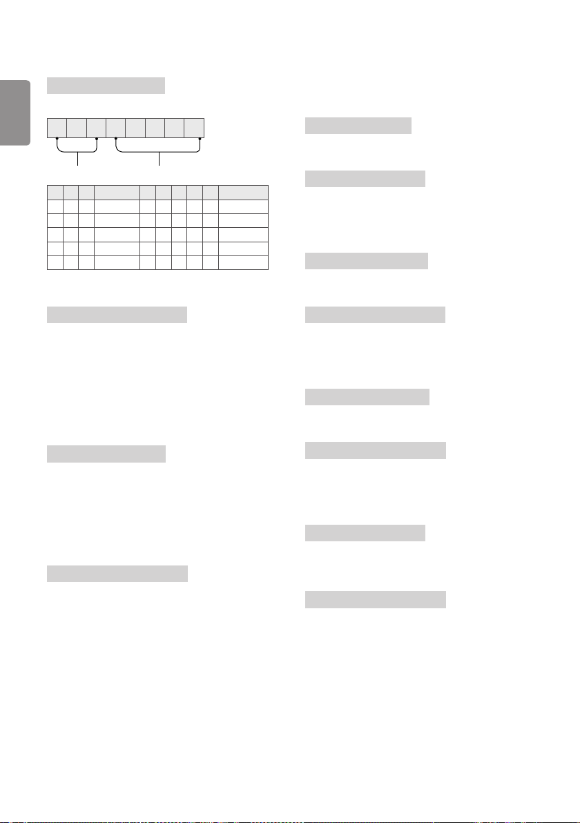
15
[Equalizer] (Command : j v)
► Adjust EQ of the set.
Transmission
[j][v][ ][Set ID][ ][Data][Cr]
ENGLISH
MSB
LSB
0 0 0 0 0 0 0 0
Frequency Data
7 6 5 Frequency 4 3 2 1 0 Step
0 0 0 1st Band 0 0 0 0 0 0(decimal)
0 0 1 2nd Band 0 0 0 0 1 1(decimal)
0 1 0 3rd Band ... ... ... ... ... ...
0 1 1 4th Band 1 0 0 1 1 19(decimal)
1 0 0 5th Band 1 0 1 0 0 20(decimal)
Ack
[v][ ][Set ID][ ][OK/NG][Data][x]
* It depends on model, and can adjust when sound
mode is EQ adjustable value.
16
[Energy Saving] (Command: j q)
(Depending upon model)
► To reduce the power consumption of the signage.
You can also adjust energy saving in picture settings.
Transmission
[j][q][ ][Set ID][ ][Data][Cr]
Data 00 : [O]
Data 01 : [Minimum]
Data 02 : [Medium]
Data 03 : [Maximum]
Data 04 : [Auto]
Data 05 : [Screen o]
Ack
[q][ ][Set ID][ ][OK/NG][Data][x]
17
Auto Configuration (Command: j u) (Only RGB
support model)
► To adjust picture position and minimize image
shaking automatically. It works only in RGB (PC)
mode.
Transmission
[j][u][ ][Set ID][ ][Data][Cr]
Data 01 : To set
Ack
[u][ ][Set ID][ ][OK/NG][Data][x]
18
Key (Command: m c)
► To send IR remote key code.
Transmission
[m][c][ ][Set ID][ ][Data][Cr]
Data : Key code - page 25
Ack
[c][ ][Set ID][ ][OK/NG][Data][x]
19
Control Backlight (Command: m g)
► To control the backlight.
Transmission
[m][g][ ][Set ID][ ][Data][Cr]
Data Min : 00 to Max : 64
Ack
[g][ ][Set ID][ ][OK/NG][Data][x]
20
Input select (Command: x b) (Main Picture Input)
► To select input source for main picture.
Transmission
[x][b][ ][Set ID][ ][Data][Cr]
Data 90 : HDMI1
Data 91 : HDMI2
Ack
[b][ ][Set ID][ ][OK/NG][Data][x]
* This function depends on model and signal.
32
Page 33

 Loading...