

Page 1
PLASMA TV
SERVICE MANUAL
CAUTION
BEFORE SERVICING THE CHASSIS,
READ THE SAFETY PRECAUTIONS IN THIS MANUAL.
CHASSIS : PA75A
MODEL : 60PY3D
60PY3DF-UJ
CANADA : http//biz.lgservice.com
USA : http//www.lgservice.com
: http//biz.lgservice.com
Internal Use Only
Page 2
- 2 -
Copyright © 2007 LG Electronics. Inc. All right reserved.
Only for training and service purposes
LGE Internal Use Only
SAFETY PRECAUTIONS
Many electrical and mechanical parts in this chassis have special safety-related characteristics. These parts are identified by in
the Schematic Diagram and Replacement Parts List.
It is essential that these special safety parts should be replaced with the same components as recommended in this manual to
prevent X-RADIATION, Shock, Fire, or other Hazards.
Do not modify the original design without permission of manufacturer.
General Guidance
An lsolation Transformer should always be used during
the servicing of a receiver whose chassis is not isolated from
the AC power line. Use a transformer of adequate power rating
as this protects the technician from accidents resulting in
personal injury from electrical shocks.
It will also protect the receiver and it's components from being
damaged by accidental shorts of the circuitary that may be
inadvertently introduced during the service operation.
If any fuse (or Fusible Resistor) in this monitor is blown, replace
it with the same specified type.
When replacing a high wattage resistor (Oxide Metal Film
Resistor, over 1W), keep the resistor 10mm away from PCB.
Keep wires away from high voltage or high temperature parts.
Leakage Current Cold Check(Antenna Cold Check)
With the instrument AC plug removed from AC source,
connect an electrical jumper across the two AC plug prongs.
Place the AC switch in the on positioin, connect one lead of
ohm-meter to the AC plug prongs tied together and touch other
ohm-meter lead in turn to each exposed metallic parts such as
antenna terminals, phone jacks, etc.
If the exposed metallic part has a return path to the chassis, the
measured resistance should be between 1MΩ and 5.2MΩ.
When the exposed metal has no return path to the chassis the
reading must be infinite.
An other abnormality exists that must be corrected before the
receiver is returned to the customer.
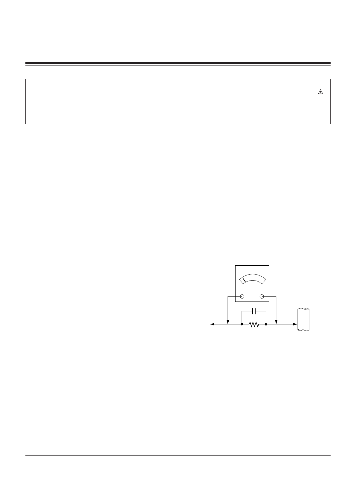
Leakage Current Hot Check (See below Figure)
Plug the AC cord directly into the AC outlet.
Do not use a line Isolation Transformer during this check.
Connect 1.5K/10watt resistor in parallel with a 0.15uF capacitor
between a known good earth ground (Water Pipe, Conduit, etc.)
and the exposed metallic parts.
Measure the AC voltage across the resistor using AC
voltmeter with 1000 ohms/volt or more sensitivity.
Reverse plug the AC cord into the AC outlet and repeat AC
voltage measurements for each esposed metallic part. Any
voltage measured must not exceed 0.75 volt RMS which is
corresponds to 0.5mA.
In case any measurement is out of the limits sepcified, there is
possibility of shock hazard and the set must be checked and
repaired before it is returned to the customer.
Leakage Current Hot Check circuit
CANADA: LG Electronics Canada, Inc. 550 Matheson
Boulevard East Mississauga, Ontario L4Z 4G3
USA : LG Customer Interactive Center
P.O.Box 240007, 201 James Record Road Huntsville,
AL 35824
Digital TV Hotline 1-800-243-0000
1.5 Kohm/10W
To Instrument's
exposed
METALLIC PARTS
Good Earth Ground
such as WATER PIPE,
CONDUIT etc.
AC Volt-meter
IMPORTANT SAFETY NOTICE
0.15uF
Page 3

- 3 -
Copyright © 2007 LG Electronics. Inc. All right reserved.
Only for training and service purposes
LGE Internal Use Only
SPECIFICATIONS.................................................................4
ADJUSTMENT INSTRUCTIONS ..........................................5
BLOCK DIAGRAM ..............................................................11
EXPLODED VIEW...............................................................20
EXPLODED VIEW PARTS LIST .........................................21
SCHEMATIC DIAGRAM..........................................................
PRINTED CIRCUIT BOARDS.................................................
TABLE OF CONTENTS
Page 4
- 4 -
Copyright © 2007 LG Electronics. Inc. All right reserved.
Only for training and service purposes
LGE Internal Use Only
SPECIFICATIONS
The specifications shown above may be changed without prior notice for quality improvement.
47LC7DF
(47LC7DF-UK)
50PY3D
50PY3DF
(50PY3DF-UJ)
60PY3D
60PY3DF
(60PY3DF-UJ)
MODELS
45.1 x 32.5x 12.1 inches
1144.3 x 825.5 x 306.4mm
45.1 x 29.7 x 4.1 inches
1144.3 x 754.7 x 103.0 mm
70.8 pounds / 32.1 kg
57.3 pounds / 26.0 kg
53.5 x 35.0 x 14.6 inches
1360.0 x 887.0 x 370.0 mm
53.5 x 32.4 x 3.8 inches
1360.0 x 822.0 x 95.5 mm
126.8 pounds / 57.5kg
107.0 pounds / 48.5kg
63.5 x 40.8 x 17.8 inches
1613.6 x 1036.8 x 452.0 mm
63.5 x 38.2 x 3.9 inches
1613.6 x 970.0 x 98.5 mm
178.6 pounds / 81.0kg
143.3 pounds / 65.0kg
AC100-240V ~ 50/60Hz
NTSC-M, ATSC, 64 & 256 QAM
VHF 2-13, UHF 14-69, CATV 1-135, DTV 2-69, CADTV 1-135
75 ohm
32 ~ 104°F (0 ~ 40°C)
Less than 80%
-4 ~ 140°F (-20 ~ 60°C)
Less than 85%
Dimensions
(Width x Height x Depth)
Weight
Power requirement
Television System
Program Coverage
External Antenna
Impedance
Environment condition
Including stand
Excluding stand
including stand
excluding stand
Operating
Temperature
Operating Humidity
Storage Temperature
Storage Humidity
Page 5
- 5 -
Copyright © 2007 LG Electronics. Inc. All right reserved.
Only for training and service purposes
LGE Internal Use Only
1. Application Range
This spec sheet is applied all of the PDP TV, PA75A chassis.
2. Specification
(1) Because this is not a hot chassis, it is not necessary to use
an isolation transformer. However, the use of isolation
transformer will help protect test equipment.
(2) Adjustments must be done in the correct order.
(3) The adjustments must be performed in the circumstance of
25±5°C of temperature and 65±10% of relative humidity if
there is no specific designation.
(4) The input voltage of the receiver be must kept 110V, 60Hz
when adjusting.
(5) The receiver must be operational for about 15 minutes
prior to the adjustments.
1) After receiving 100% white pattern, the receiver must be
operated prior to adjustment. (Or 8. Test Pattern
condition in EZ - Adjust)
2) Enter into White Pattern
- Press POWER ON Key on the Service Remote
Control (S R/C)
- Enter the Ez - Adjust by pressing ADJ Key on the
Service Remote Control (S R/C).
- Select 10. Test Pattern using the CH +/- Key and
select the White by pressing the direction Key.
Display the 100% Full White Pattern.
[ Set is activated HEAT-RUN without signal generator in
this mode.
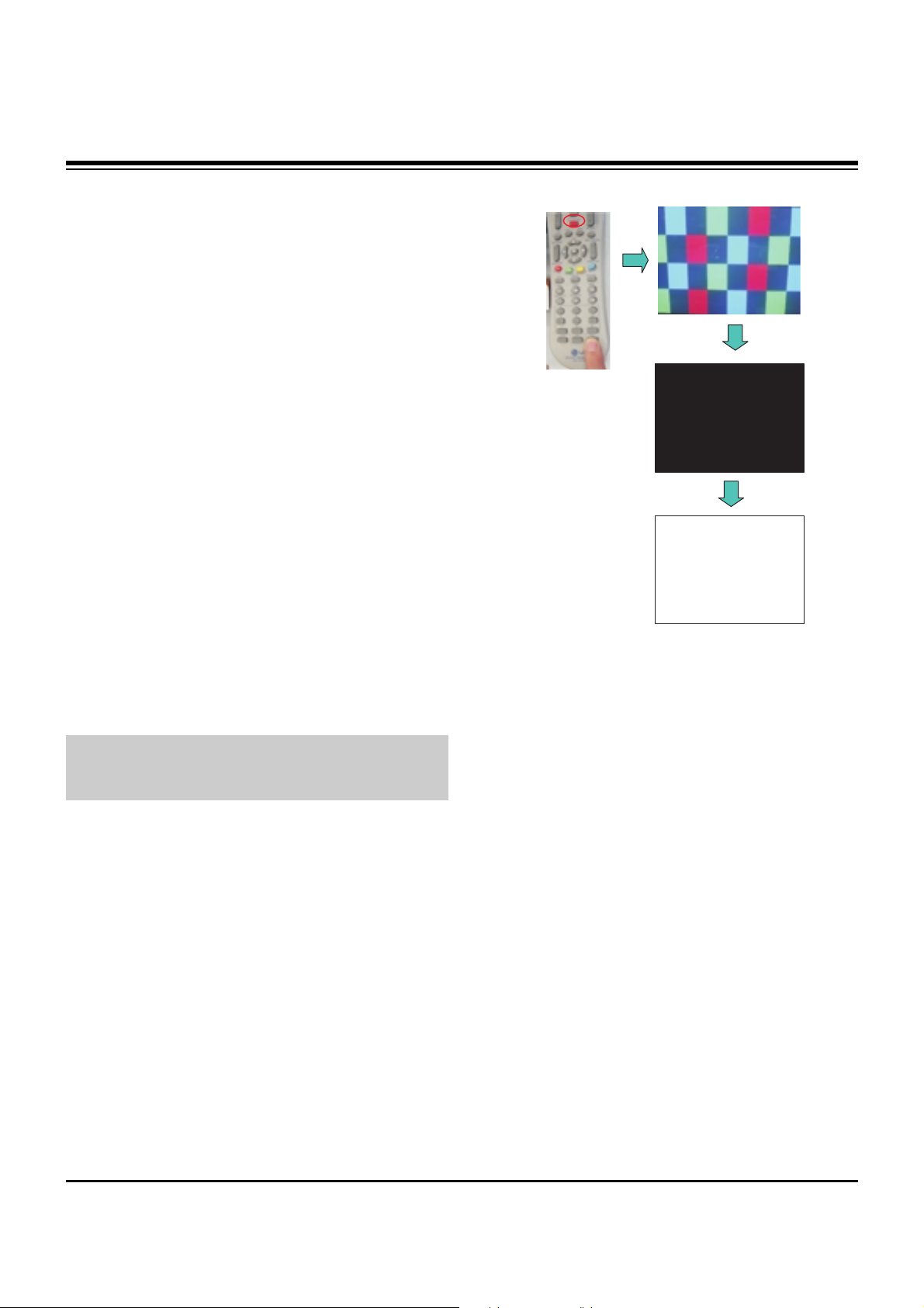
O HEAT RUN
Preliminary action is applied to the test for afterimage
discharge detection, and 100% FULL WHITE PATTERN
must be operated automatically.
O Test for afterimage discharge detection
1) Pressing Power On key
- Only operating by pressing Power On key
2) Full Test Pattern(2 min 30sec) --> Full Black
Pattern(30sec) --> Full White Pattern(maintenance)
- Full White Pattern when the main power is turned on
again after being turned off
3) Pattern Mode is deselected by pressing CH +/-, Exit Key.
[ Set is activated HEAT-RUN without signal generator in this
mode.
ADJUSTMENT INSTRUCTIONS
If you turn on a still screen more than 20 minutes (Especially
Digital pattern(13 CH), Cross Hatch Pattern), an afterimage
may occur in the black level part of the screen.
Test Pattern 2min 30sec
Test Pattern 30sec
Page 6
- 6 -
Copyright © 2007 LG Electronics. Inc. All right reserved.
Only for training and service purposes
LGE Internal Use Only
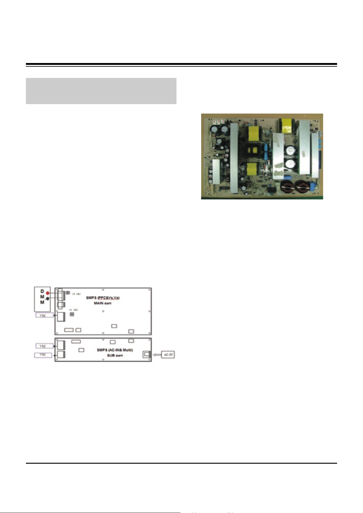
3. PSU(Power Supply Unit) Voltage
Adjustment
(Va, Vs Voltage Adjustment)
Adjust the voltages Va and Vs supplied from the PSU to the
module within the specified range of each module to supply
the stable power
3-1. Test Equipment
(1) D.M.M 1EA
(2) Voltage adjustment bar
3-2. Adjustment(60”)
(1) Va Voltage Adjustment
1) Connect + terminal of D.M.M to Va pin of P812 and
connect – terminal to GND pin of P812.
2) Adjust VR901 voltage to match that of the label on the
Top/Right of the panel. (Deviation : ±0.5V)
(2) Vs Voltage Adjustment
1) Connect + terminal of D.M.M to Vs pin of P812 and
connect – terminal to GND pin of P812.
2) Adjust VR951 voltage to match that of the label on the
Top/Right of the panel. (Deviation : ±0.5V)
3-3. Adjustment (50”)
(1) Va Adjustment
1) Connect + terminal of D.M.M to Va pin of P12 and
connect – terminal to GND pin of P12.
2) Adjust VR951 voltage to match that of the label on the
Top/Right of the panel. (Deviation : ±0.5V)
(2) Vs Adjustment
1) Connect + terminal of D.M.M to Vs pin of P12 and
connect – terminal to GND pin of P12.
2) Adjust VR901 voltage to match that of the label on the
Top/Right of the panel. (Deviation : ±0.5V)
ADJUSTMENT INSTRUCTIONS
Each PCB assembly must be checked by check JIG set.
(Because power PCB Assembly damages to PDP Module,
especially be careful)
Connection Diagram of Power Adjustment for Measuring
(Power Board): 60”
Connection Diagram of Power Adjustment for Measuring
(Power Board): 50”
Page 7
- 7 -
Copyright © 2007 LG Electronics. Inc. All right reserved.
Only for training and service purposes
LGE Internal Use Only
4. Component 480i/1080p RGB
1080p Adjustment
Component 480i/1080p RGB 1080p adjustment to set the
black level and the Gain to optimum.
4-1. Test Equipment
(1) Service R/C
(2) 801GF(802B, 802F, 802R) or MSPG925FA Pattern
Generator (480i/1080p The Horizontal 100% Color Bar
Pattern adjust to within 0.7±0.1Vp-p)
[ Because the above pattern can differ by the model and
pattern for each device, you must check the pattern first.
4-2. ADC 480i Component1 Adjustment
(1) Check the connection Component1 to the Test Equipment.
(MSPG-925FA => Model: 209, Pattern: 65)
(2) Select Component1 as the input with 100% Horizontal
Color Bar Pattern(HozTV31Bar) in 480i Mode and select
‘Normal’ in screen.
(3) After receiving signal for at least 1 second, press the ADJ
Key on the Service R/C to enter the ‘Ez - Adjust’ and select
the ‘3. ADC 480i Comp1’.
Pressing the Enter Key to adjust automatically.
(4) When the adjustment is over, 'ADC Component1 Success’
is displayed.
(5) If the adjustment has errors, 'ADC Component1 480i Fail’
is displayed. And error massage(‘Component1 Not
Connected’ or ‘Not Valid Format’ or ‘Check Signal Status’)
is displayed for 1 second.
4-3. ADC 1080p Component1/RGB
Adjustment
(1) Check the connection Component1, RGB to the Test
Equipment (MSPG-925FA => Model: 225, Pattern: 65)
(2) Select Component1 as the input with 100% Horizontal
Color Bar Pattern(HozTV31Bar) in 1080p Mode and select
‘Normal’ in screen.
(3) After receiving signal for at least 1 second, press the ADJ
Key on the Service R/C to enter the ‘Ez - Adjust’ and select
the ‘4. ADC 1080p Comp1/RGB’.
Pressing the Enter Key to adjust automatically component1.
(4) When the adjustment is over, 'ADC Component1 Success’
is displayed. If the adjustment has errors, 'ADC
Component1 1080p Fail’ is displayed.
(5) After the Component1 adjustment is over, convert the
RGB-DTV Mode and start RGB adjustment.
When the adjustment is over, 'ADC RGB 1080P Success’
is displayed.
(6) Readjust after confirming the case Pattern or adjustment
condition where the adjustment errors.
Error massage is ‘Component1 Not Connected’ or ‘Not
Valid Format’ or ‘Check Signal Status’.
(7) After adjustment is complete, exit the adjustment mode by
pressing the ADJ KEY.
5. EDID(The Extended Display
Identification Data)/DDC
(Display Data Channel) Download
It is the feature to implement the “Plug and Play” which
automatically reconfigures the user’sl environment to directly
use by exchanging information without any command directly
to the PC or the monitor by the user, which is established by
the VESA
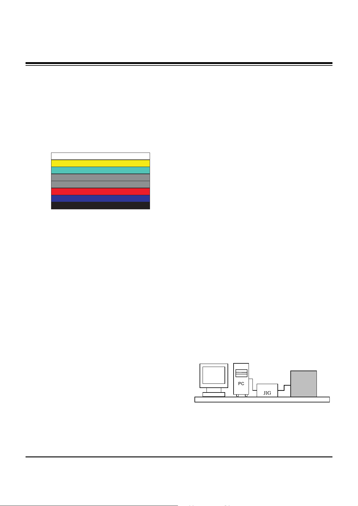
5-1. HDMI EDID Data Input
(1) Required Test Equipment
1) PC, Jig for adjusting DDC. (PC serial to D-sub
Connection equipment)
2) S/W for writing DDC(EDID data write & read)
3) D-Sub cable
4) Jig for HDMI Cable connection
(2) Preparation for Adjustments &
Setting of Device
1) Set devices as below and turn on the PC and JIG.
2) Open S/W for writing DDC (EDID data write & read).
(operated in DOS mode)
ADJUSTMENT INSTRUCTIONS
<Fig. 1> Adjustment Pattern: 480i/1080p 60Hz Pattern
LCD TV SET
(or Digital Board)
Page 8

- 8 -
Copyright © 2007 LG Electronics. Inc. All right reserved.
Only for training and service purposes
LGE Internal Use Only
5-2. EDID DATA for PA75A
: EDID for HDMI-1 (DDC (Display Data Channel) Data)
EDID table =
0 1 2 3 4 5 6 7 8 9 A B C D E F
__________________________________________________
0 | 00 FF FF FF FF FF FF 00 1E 6D 01 00 01 01 01 01
10 | 00 11 01 03 80 73 41 96 0A CF 74 A3 57 4C B0 23
20 | 09 48 4C AF CF 00 31 40 45 40 61 40 81 80 A9 40
30 | 01 01 01 01 01 01 66 21 50 B0 51 00 1B 30 40 70
40 | 36 00 C4 8E 21 00 00 1E 02 3A 80 18 71 38 2D 40
50 | 58 2C 45 00 C4 8E 21 00 00 1E 00 00 00 FD 00 30
60 | 58 1F 64 11 00 0A 20 20 20 20 20 20 00 00 00 FC
70 | 00 4C 47 20 54 56 0A 20 20 20 20 20 20 20 01 8A
0 1 2 3 4 5 6 7 8 9 A B C D E F
__________________________________________________
0 | 02 03 18 F1 47 84 05 03 02 20 22 10 23 15 07 50
10 | 67 03 0C 00 10 00 B8 2D 01 1D 00 72 51 D0 1E 20
20 | 6E 28 55 00 C4 8E 21 00 00 1E 01 1D 80 18 71 1C
30 | 16 20 58 2C 25 00 C4 8E 21 00 00 9E 8C 0A D0 8A
40 | 20 E0 2D 10 10 3E 96 00 C4 8E 21 00 00 18 8C 0A
50 | D0 8A 20 E0 2D 10 10 3E 96 00 13 8E 21 00 00 18
60 | 26 36 80 A0 70 38 1F 40 30 20 25 00 C4 8E 21 00
70 | 00 1A 00 00 00 00 00 00 00 00 00 00 00 00 00 27
: EDID for HDMI-2 (DDC (Display Data Channel) Data)
EDID table =
0 1 2 3 4 5 6 7 8 9 A B C D E F
__________________________________________________
0 | 00 FF FF FF FF FF FF 00 1E 6D 01 00 01 01 01 01
10 | 00 11 01 03 80 73 41 96 0A CF 74 A3 57 4C B0 23
20 | 09 48 4C AF CF 00 31 40 45 40 61 40 81 80 A9 40
30 | 01 01 01 01 01 01 66 21 50 B0 51 00 1B 30 40 70
40 | 36 00 C4 8E 21 00 00 1E 02 3A 80 18 71 38 2D 40
50 | 58 2C 45 00 C4 8E 21 00 00 1E 00 00 00 FD 00 30
60 | 58 1F 64 11 00 0A 20 20 20 20 20 20 00 00 00 FC
70 | 00 4C 47 20 54 56 0A 20 20 20 20 20 20 20 01 8A
0 1 2 3 4 5 6 7 8 9 A B C D E F
__________________________________________________
0 | 02 03 18 F1 47 84 05 03 02 20 22 10 23 15 07 50
10 | 67 03 0C 00 20 00 B8 2D 01 1D 00 72 51 D0 1E 20
20 | 6E 28 55 00 C4 8E 21 00 00 1E 01 1D 80 18 71 1C
30 | 16 20 58 2C 25 00 C4 8E 21 00 00 9E 8C 0A D0 8A
40 | 20 E0 2D 10 10 3E 96 00 C4 8E 21 00 00 18 8C 0A
50 | D0 8A 20 E0 2D 10 10 3E 96 00 13 8E 21 00 00 18
60 | 26 36 80 A0 70 38 1F 40 30 20 25 00 C4 8E 21 00
70 | 00 1A 00 00 00 00 00 00 00 00 00 00 00 00 00 17
: EDID for HDMI-3 (DDC (Display Data Channel) Data)
EDID table =
0 1 2 3 4 5 6 7 8 9 A B C D E F
__________________________________________________
0 | 00 FF FF FF FF FF FF 00 1E 6D 01 00 01 01 01 01
10 | 00 11 01 03 80 73 41 96 0A CF 74 A3 57 4C B0 23
20 | 09 48 4C AF CF 00 31 40 45 40 61 40 81 80 A9 40
30 | 01 01 01 01 01 01 66 21 50 B0 51 00 1B 30 40 70
40 | 36 00 C4 8E 21 00 00 1E 02 3A 80 18 71 38 2D 40
50 | 58 2C 45 00 C4 8E 21 00 00 1E 00 00 00 FD 00 30
60 | 58 1F 64 11 00 0A 20 20 20 20 20 20 00 00 00 FC
70 | 00 4C 47 20 54 56 0A 20 20 20 20 20 20 20 01 8A
0 1 2 3 4 5 6 7 8 9 A B C D E F
__________________________________________________
0 | 02 03 18 F1 47 84 05 03 02 20 22 10 23 15 07 50
10 | 67 03 0C 00 30 00 B8 2D 01 1D 00 72 51 D0 1E 20
20 | 6E 28 55 00 C4 8E 21 00 00 1E 01 1D 80 18 71 1C
30 | 16 20 58 2C 25 00 C4 8E 21 00 00 9E 8C 0A D0 8A
40 | 20 E0 2D 10 10 3E 96 00 C4 8E 21 00 00 18 8C 0A
50 | D0 8A 20 E0 2D 10 10 3E 96 00 13 8E 21 00 00 18
60 | 26 36 80 A0 70 38 1F 40 30 20 25 00 C4 8E 21 00
70 | 00 1A 00 00 00 00 00 00 00 00 00 00 00 00 00 07
: EDID DATA for RGB
EDID table =
0 1 2 3 4 5 6 7 8 9 A B C D E F
__________________________________________________
0 | 00 FF FF FF FF FF FF 00 1E 6D 01 00 01 01 01 01
10 | 00 11 01 03 18 73 41 96 0A CF 74 A3 57 4C B0 23
20 | 09 48 4C AF CF 00 31 40 45 40 61 40 81 80 A9 40
30 | 01 01 01 01 01 01 66 21 50 B0 51 00 1B 30 40 70
40 | 36 00 C4 8E 21 00 00 1A 02 3A 80 18 71 38 2D 40
50 | 58 2C 45 00 C4 8E 21 00 00 1E 00 00 00 FD 00 30
60 | 58 1F 64 11 00 0A 20 20 20 20 20 20 00 00 00 FC
70 | 00 4C 47 20 54 56 0A 20 20 20 20 20 20 20 01 F6
0 1 2 3 4 5 6 7 8 9 A B C D E F
__________________________________________________
0 | 02 03 04 00 0E 1F 00 80 51 00 1E 30 40 80 37 00
10 | C4 8E 21 00 00 1C F1 27 00 A0 51 00 25 30 50 80
20 | 37 00 C4 8E 21 00 00 1C 26 36 80 A0 70 38 1F 40
30 | 30 20 25 00 C4 8E 21 00 00 0A 00 00 00 00 00 00
40 | 00 00 00 00 00 00 00 00 00 00 00 00 00 00 00 00
50 | 00 00 00 00 00 00 00 00 00 00 00 00 00 00 00 00
60 | 00 00 00 00 00 00 00 00 00 00 00 00 00 00 00 00
70 | 00 00 00 00 00 00 00 00 00 00 00 00 00 00 00 BC
ADJUSTMENT INSTRUCTIONS
Page 9

- 9 -
Copyright © 2007 LG Electronics. Inc. All right reserved.
Only for training and service purposes
LGE Internal Use Only
6. Adjustment of White Balance
6-1. Required Test Equipment
(1) Color Analyzer : CA-210 (CH 10), CA-100(CH 10), CA-
100+(CH 10)
=> To adjust color temperature of PDP, CS-1000 is the
Color Analyzer and should be set to use CH 10in which
white, red, green, and blue color are corrected. Conduct
the adjustment according to the coordinates for White
Balance adjustment in the table below.
(2) Computer for adjusting (necessary for the automatic
adjustment, possible to communicate with the RS-232C,
Baud Rate : 115200)
(3) Video Signal Generator MSPG-925F 720p, 216Gray
(Model :217, Pattern 78)
6-2. Connection Diagram of Equipment
for Measuring
(Automatic Adjustment)
6-3. White Balance Adjustment Method
Basically it uses the internal pattern but when internal pattern
is not possible, you can select HDMI input for adjustment.
Through the option at the most bottom part of the Ez Adjust
Menu 7.White Balance menu, you can select NONE, INNER
and HDMI, and the default is set to INNER. When the
adjustment cannot be done with the internal pattern, you can
select HDMI input for adjustment.
For manual adjustment, press the ADJ KEY of the adjustment
R/C to enter Ez Adjust 7.White-Balance, and the pattern is
automatically displayed. (When you set the Option to INNER,
the default is always set to INNER)
(1) Connect the set according to the internal pattern or HDMI
input in accordance with measuring device connection
diagram.
(2) Set the Baud Rate of RS-232C to 115200. It is set to
115200 as default.
(3) Connect the RS-232C Cable to the set.
(4) Connect the HDMI Cable to the set. (Limited to the set with
HDMI option)
(5) Select and adjust the model applicable to PA75A chassis
from the adjuster.
[RS-232C command used for the automatic adjustment]
Ô Wb 00 00-----white balance Automatic Adjustment Start
Ô Wb 00 10-----Gain Adjustment start (Internal pattern)
Ô Ja 00 ff------Adjustment Data
Ô Jb 00 c0
Ô ...
Ô Wb 00 1f-----Gain Adjustment End
Ô *(wb 00 20(Start), wb 00 2f(End))----- When adjust Off-set
Ô Wb 00 ff------White Balance Automatic Adjustment End
(Disappear Inside pattern)
[Adjustment Map]
ADJUSTMENT INSTRUCTIONS
(internal pattern)
Connection Diagram for Internal Pattern
Connection Diagram for HDMI Input
wb
wb
wb
wb
wb
wb
00
00
00
00
00
00
00
10
1f
20
2f
ff
White Balance Adjustment Start
Gain Adjustment Start(Internal white pattern)
Gain Adjustment End
Offset Adjustment Start(Internal white pattern)
Offset Adjustment End
White Balance Adjustment End
(Disappear Internal pattern)
RS-232C COMMAND
[CMD ID DATA]
Meaning
R Gain
G Gain
B Gain
R Cut
G Cut
B Cut
Jg
Jh
Ji
Cool
Ja
Jb
Jc
Mid
RS-232C COMMAND
[CMD ID DATA]
CENTER
(DEFAULT)
Jd
Je
Jf
00
00
00
192
192
192
127
127
127
Warm
Min Max
184
187
192
64
64
64
Cool
192
183
161
64
64
64
Mid
192
159
95
64
64
64
Warm
Page 10

- 10 -
Copyright © 2007 LG Electronics. Inc. All right reserved.
Only for training and service purposes
LGE Internal Use Only
6-4. Automatic Adjustment
(1) Execute POWER ON(Â) of the adjustment R/C to execute
automatic adjustment.
(2) Set the Baud Rate to 115200.
(3) Always start adjustment with “wb 00 00” and end
adjustment with “wb 00 ff”
(4) Adjust the offset if necessary
6-5. Manual Adjustment
(1) Required Test Equipment: CA-210 (CH 10), CA-100(CH
10), CA-100+(CH 10)
=> To adjust color temperature of PDP, CS-1000 is the
Color Analyzer and should be set to use CH 10 in which
white, red, green, and blue color are corrected. Conduct
the adjustment according to the coordinates for White
Balance adjustment in the table below.
(2) Enter the ‘Ez - Adjust’ by pressing the ADJ on the Service
R/C.
(3) Select 10.TEST PATTERN using the CH + / - KEY and
press the Enter KEY to execute a heat run for more than
30 minutes.
(4) Zero Calibrate CA-100+/CA-100 Probe, and stick the
sensor to the center of PDP module surface when you
adjust.
Execute a Zero Calibration for CA-210 Probe and put it at
distance of less than 10Cm from the PDP module surface
center during the adjustment.
(5) Select ‘7. White-Balance’ of ‘Ez - Adjust’ by pressing the
ADJ KEY on the Service R/C. Then enter adjustment mode
by pressing the Right KEY (
G
) .
(The internal pattern of full white appears by pressing
G
)
(6) The adjustment is conducted in three levels of color
temperature; COOL, MEDIUM, and WARM.
1) When R GAIN is set to 192
- Control G GAIN and B GAIN by lowering from 192.
2) When B GAIN is set to 192
- Control R GAIN and G GAIN by lowering from 192.
3) When G GAIN is set to 192
- Control R GAIN and B GAIN by lowering from 192.
One of R Gain / G Gain / B Gain should be kept on 192,
and adjust other two lower than 192.
(When R/G/B GAIN are all 192, it is the FULL DYNAMIC
Range of Module)
(7) Use the Vol. +, - key for adjustment.
(8) When the adjustment is completed, press the ENTER (
Á
KEY) button to move to the Ez –Adjust screen. Press the
ADJ KEY to exit the adjustment mode.
[
White Balance
Full white 216gray
ADJUSTMENT INSTRUCTIONS
Mode Temp ∆ uv
Color Coordination
Cool
Medium
Warm
11,000K
9,300K
6,500K
0.000
0.003
0.003
x
0.276±0.002
0.283±0.002
0.313±0.002
y
0.283±0.002
0.297±0.002
0.329±0.002
Page 11

- 11 -
Copyright © 2007 LG Electronics. Inc. All right reserved.
Only for training and service purposes
LGE Internal Use Only
BLOCK DIAGRAM
Block Diagram - Overview
Audio L/R
Flash
(16MB)
74LVC14APW
TEA6420
(Audio
SW)
MC33078
(AMP)
CS5340
(A/D)
MTV416
(Micom)
NTP3000
(Digital AMP)
X-tal(54M)
TMDS341A
(3x1,S/W)
74F08D
EEPROM
AT/NT
Tuner
64Bit I/F
Reset
CVBS
CVBS/Y/C
Y/Cb/Cr
R/G/B
H/V Sync
RGB-PC
HDMI
0/1/2
COMP 1
COMP 2
AV 1
AV 2
RGB-PC
Audio L/R
I2S
MNT out
( L/R)
SPDIF OUT
I2S
RS-232C
Dead IC when Standby
Option
Alive IC when Standby
Video
Audio
Video
Front
End
Dual
HDMI
Rx
HD/SD
Video
Encoder
Audio
DSP
BCM3553
MCLK
MCLK
HDMI CEC
HDMI CEC
(To Micom)
To Micom
SDA
SCL
SIF
IF(AT)
Buffer
Single LVDS
Connector
Digital out FHD
Local KEY
IR
Buffer Buffer
24C16
AGC CTL (From BCM)
USB2.0
I2S Audio Input
VSB/QAM/NTSC/SIF
DDR(128MB)
DDR(128MB)
Page 12

- 12 -
Copyright © 2007 LG Electronics. Inc. All right reserved.
Only for training and service purposes
LGE Internal Use Only
BLOCK DIAGRAM
Signal path for CVBS, Component, RGB
Comp1_Y
H Sync
V Sync
BCM3553
Comp1_Pb
Comp1_Pr
74F08D
Component 1
Input
Component 2
Input
RGB Input
RGB H_Sync
Side AV CVBS
Rear AV
Rear S_Video Y/C
Side S_Video
Y/C
CVBS
CVBS 2
L1/C1
CVBS 3
L2/C2
ANT/ Cable
TUNER
IF_P
IF_N
IF_P from TUNER for DTV
IF_N from TUNER for DTV
CVBS 1
EEPROM
FOR EDID
DDC SDA
DDC SCL
RGB V_Sync
LVDS_Tx
Out
Only for HD
Component_1 S/W
Component_2 S/W
Rear_CVBS_ S/W
RGB S/W
GPIO[0:6]
Comp2_Y
Comp2_Pb
Comp2_Pr
RGB_G
RGB_B
RGB_R
DDC SCL to Micom
for Download
LPF 6 Mhz
LPF 30Mhz
LPF 30Mhz
LPF 30Mhz
LPF 30Mhz
LPF 30Mhz
LPF 30Mhz
LPF 6 Mhz
LPF 6 Mhz
LPF 6 Mhz
DDC SDA to Micom
for Download
DVO Out[0:29]
Rear_S-Video_ S/W
Side_CVBS_ S/W
Side_S-Video_ S/W
31p
LVDS
Con.
31p
LVDS
Con.
¥74F08D : Bi-quad 2 input AND Gate
- CAX2181을 사용하여 System Design할 경우,
특정 Format 입력일 때, Sync틀어짐 현상이
생기는 것을 보상하고자 사용 함.
Page 13

- 13 -
Copyright © 2007 LG Electronics. Inc. All right reserved.
Only for training and service purposes
LGE Internal Use Only
BLOCK DIAGRAM
BCM3553
TMDS0 RX0+/-
TMDS0 RX1+/-
TMDS0 RX2+/-
TMDS0 RXCLK+/-
DDC SDA0
DDC SCL0
EEPROM
For EDID
HDCP SDA
HDCP SCL
NDA
NCL
HDMI 0
HDMI 1
HDMi — CEC
+5V Power_0
Hot Plug Detect_0
TMDS1 RX0+/-
TMDS1 RX1+/-
TMDS1 RX2+/-
TMDS1 RXCLK+/-
DDC SDA1
DDC SCL1
EEPROM
For EDID
HDMi — CEC
+5V Power_1
Hot Plug Detect_1
LVDS_Tx
Out
HDMI 2
TMDS2 RX0+/-
TMDS2 RX1+/-
TMDS2 RX2+/-
TMDS2 RXCLK+/-
DDC SDA2
DDC SCL2
EEPROM
For EDID
HDMi — CEC
+5V Power_2
Hot Plug Detect_2
TMDS341A
TMDS0
INPUT
DDC SDA
DDC SCL
TMDS1
INPUT
TMDS2
INPUT
TMDS RX0+/-
TMDS RX1+/-
TMDS RX2+/-
TMDS RXCLK+/-
Hot Plug Detect_0
TMDS
Out
TMDS_Rx
Input
HDMi_Sel_0
HDMi_Sel_1
HDMi_Sel_2
Hot Plug Detect_1
Hot Plug Detect_2
+5V Power_0
+5V Power_1
+5V Power_2
GPIO[0:8]
Switch
Selection
DDC
INPUT
MTV416
MTV416
Micom
HDMi — CEC
Parallel connections with
HDMi 0,1,2
Only for HD 31P
LVDS
Con.
31P
LVDS
Con.
DVO Out[0:29]
EEPROM
for HDCP
EEPROM
for HDCP
DDC SDA0
DDC SCL0
DDC SDA1
DDC SCL1
DDC SDA2
DDC SCL2
DDC
OUT
Page 14

- 14 -
Copyright © 2007 LG Electronics. Inc. All right reserved.
Only for training and service purposes
LGE Internal Use Only
BLOCK DIAGRAM
AV1_Audio
AV2_Audio
MNT_Audio
HDMI
(PC/DTV)
Comp2_Audio
RGB_Audio
Comp1_Audio
[L1 / R1]
[L2 / R2]
[L3 / R3]
[L4 / R4]
[L5 / R5]
Switch
Switch
[Rout/Lout]
I2C SCL/SDA
Audio
Switch
[TEA6420]
AUDIO ADC
[CS5340]
I2S_CLK_IN/DATA_IN
/LR IN
(I2S_MCLK)
SPDIF OUT
Buffer
Buffer
OP AMP
[MC33078]
PWM MODULATOR/
POWER AMP
[NTP3000]
SIF IN
Broadcom
[BCM3553]
AUD_SPDIF
ANA L/R IN
ANA L/R
(MC33078)
ANA L/R
ANA L/R OUT
(CS5340)
BCM_MCLK
BCM_MCLK
I2S_CLK_IN
I2S_DATA_IN
I2S_LR_IN
RESET
RESET
I2S_CLK_OUT
I2S_DATA_OUT
I2S_LR_OUT
(NTP3000)
I2S_CLK_OUT/
DATA_OUT/
LRCH OUT
I2C SCL/SDA
OUT1A/B
OUT2A/B
SPK R
SPK L
MNT_L/R OUT
HDMI Rx
Built in
Internal
I2S/SPDIF
Convert
HDMI_TMDS 0/1/2/CLK
TUNER (ATSC/NTSC )
I2C SCL/SDA
Buffer
Buffer
SIF
IF_P
IF_N
AUD_LEFT/RIGHT P
HDMI_RX_DATA/CLK
ANA L/R OUT
BTSC
Decoder
MPEG2
Dolby
AUDIO
Processor
Signal path for AUDIO/ IF
SPDIF OUT(coaxial)
BCM_MCLK
IF AGC
CVBS
FRONT END
Page 15

- 15 -
Copyright © 2007 LG Electronics. Inc. All right reserved.
Only for training and service purposes
LGE Internal Use Only
BLOCK DIAGRAM
BCM3553
AUDIO S/W(TEA6420)
NTP3000
NVRAM
4.7K‰
5.0V
I2C_Channel 0
I2C_Channel 1
ATSC/NTSC Tuner
I2C_Channel 2
I2C_Channel 3
I2C0_5V
I2C1_5V
I2C2_2.5V
I2C2_3.3V
I2C3_3.3V
MTV416
4.7K‰
3.3VST
1K‰
3.3V
M62320
4.7K‰
5.0V
LM57(DS1621)
HDCP Key EEPROM
Address
0xC2
0x9A
0x74
0xA6
0x94
0x1C
0x54
0x??
0xD4
PDP MODULE
0x50
I2C MAP
CAT6431 Ready
(only S/W mode)
Page 16

- 16 -
Copyright © 2007 LG Electronics. Inc. All right reserved.
Only for training and service purposes
LGE Internal Use Only
BLOCK DIAGRAM
Power Sequence and Flow Diagram
P_+19V
P_+19V
IC501
NTP3000
(Sound IC)
BIAS
Speaker R/L
+12.0V
+12.0V
IC806
KA7809
IC500
TEA6420D
(Audio SW)
+9V
IC504
MC33078
(OP AMP)
Digital eye
LCD control B/D
IC901,902
KIA78R09F
(FAN REG)
FAN
FAN
REG IC BIAS Side power
Page 17

- 17 -
Copyright © 2007 LG Electronics. Inc. All right reserved.
Only for training and service purposes
LGE Internal Use Only
BLOCK DIAGRAM
Power Sequence and Flow Diagram
ST_5V
ST_5V
REG IC BIAS Side power
Local key/IR power
IC202
ICL3232
RS-232C RX/TX
IC404
AZ1117H-3.3
IC406
AT24C16AN
(EEPROM)
+3.3VST_MICOM
IC407
MTV416GMF
( micom )
BIAS
HDMI CEC
Inv/RL/live-on
3.3V->5V
BIAS
Page 18

- 18 -
Copyright © 2007 LG Electronics. Inc. All right reserved.
Only for training and service purposes
LGE Internal Use Only
BLOCK DIAGRAM
Power Sequence and Flow Diagram
+6.0V
+6.0V
REG IC BIAS Side power
IC800
PQ05DZ1U
TUNER
+5V_TU
Power_CTL_3.3V
Tuner SIF
IC801
PQ05DZ1U
+5.0V
IC102
CAT24WC
(HDCP KEY EEPROM)
BIAS
BCM PCI 단
BCM SCL/SDA0~1
BCM DS-AGC,AUD_VDD
BIAS
IC200
TPS2052
(USB power CTL
analog SW)
IC403
AT24C512W
(EEPROM NVRAM)
Inv/RL/live-on
3.3V->5V
IC502
CS5340
(Audio ADC)
입력단자 HPD
IC601/602/603/701
AT24C02BN
(EEPROM EDID)
EDID EEPROM
W/P
IC600
3:1HDMI SW
SCL/SDA
IC700
74F08D
(RGB HV AND GATE)
IC808
FMS6400
(Tuner video buffer)
IC900
M62320FP
(FAN driver)
IC903
LM75CIMX-3
(FAN 온도센서)
IC804
AZ1117H-3.3
IC802
AZ1117H-3.3
D3.3V_BCM
IC101
Flash MEM 32M
Reset SWBCM3553
IC401
74LVC14ADW
Reset 슈미트트리거
A3.3V_BCM
BCM3553
DAC/USB,AGC,HDMI
BOOT
STRAP
IC600
PICHDMI341
HDMI 3:1 SW
3.3V_TMDS_SW
Page 19

- 19 -
Copyright © 2007 LG Electronics. Inc. All right reserved.
Only for training and service purposes
LGE Internal Use Only
BLOCK DIAGRAM
Power Sequence and Flow Diagram
+3.3V
+3.3V
REG IC BIAS Side power
Power_CTL_2.6V_1.2V
IC803
SC1566I5M
D2.6V_BCM
BCM3553
IC300,301,302,303
DDR IC 전원
IC200,201
TPS2052BD
(USB analog SW)
IC501
NTP3000
(sound IC)
IC502
CS5340
(Audio ADC)
IC503
TC74VHC04FT
( coxial SPDIF IC)
JK501
SPDIF power
IC407
MTV416GMF
+3.3V detect signal
BIAS
LVDS Tuner CTR
IC304
5C25955TR
DDR Memory
DDR0_VTT
DDR0_REF
BCM3553
A2.6V_BCM
IC805
SC4519STRT
DC-DC converter
BCM3553
D1.2V_BCM
A1.2V_BCM
Power_CTL_2.6V_1.2V
IC807
AZ1117H-1.8
IC501
NTP3000
(sound IC)
+1.8V_NTP
Page 20

- 20 -
Copyright © 2007 LG Electronics. Inc. All right reserved.
Only for training and service purposes
LGE Internal Use Only
EXPLODED VIEW
400
240
602
600
303
304
306
307
121
300
302
301
305
120
603
601
580
581
582
260
250
208
201
202
203
204
204
200
205
206
209
207
205
206
207
560
570
540
542
541
502
520
501
590
A21
A2
901
900
Page 21

- 21 -
Copyright © 2007 LG Electronics. Inc. All right reserved.
Only for training and service purposes
LGE Internal Use Only
EXPLODED VIEW PARTS LIST
120 EAB33735401 Speaker Assembly,50PY3 SLIM SPEAKER ASSY RIGHT
121 EAB33735402 Speaker Assembly,50PY3 SLIM SPEAKER LEFT ASSY
200 EAJ32791801 PDP,Module-FullHD PDP60H10000.ADLGB FULLHD 60INCH 1920X1080 16/9 PDP DIVISION
201 EBR32922301 PCB Assembly,EBR32922301 CTRL ASS’Y 60 H1 Full-HD CTRL PDP DIVISION
202 EBR32015901 PCB Assembly,EBR32015901 YDRV ASS’Y 60 H1 Full-HD YDRV TOP PDP DIVISION
203 EBR32016101 PCB Assembly,EBR32016101 YDRV ASS’Y 60 H1 Full-HD YDRV BOTTOM PDP DIVISION
204 EBR32003901 PCB Assembly,EBR32003901 XRLB ASSY 60 H1 Full-HD XLB & XRT PDP DIVISION
205 EBR32004501 PCB Assembly,EBR32004501 XRCLBT ASSY’ 60 H1 Full-HD XCLB & XCRT PDP DIVISION
206 EBR32004601 PCB Assembly,EBR32004601 XRCRBT ASSY’ 60 H1 Full-HD XCRB & XCLT PDP DIVISION
207 EBR32004701 PCB Assembly,EBR32004701 XRRB ASSY 60 H1 Full-HD XRB & XLT PDP DIVISION
208 EBR32324201 PCB Assembly,EBR32324201 YSUS ASS’Y 60 H1 Full HD PDP DIVISION
209 EBR32324301 PCB Assembly,EBR32324301 ZSUS ASS’Y 60 H1 Full HD PDP DIVISION
240 AJJ30996203 Supporter Assembly,60PY30, SKD, Vertical Supporter Right Assy.
250 AJJ30996204 Supporter Assembly,60PY30, SKD, Vertical Supporter Left Assy.
260 AJJ31606903 Supporter Assembly,60PY30, MODULE SUPP_SIDE HOR.+ SUPP_SIDE. PANTON ASSY
300 ABJ30995004 Cabinet Assembly,60PY3DR-UA PA71A 60 LG, C/SKD
301 ADV31660202 Frame Assembly,60py30 mf-056l 60 frame assy, LG
302 MBH32314201 Cabinet,MOLD ABS 60PY30 ABS E3, Cabinet, XCANVAS
303 AJJ30996402 Supporter Assembly,60PY30, Filter Supporter Top, SKD
304 AJJ30996502 Supporter Assembly,60PY30, Filter Supporter Bottom Assy C/SKD
305 5230V00026B Filter,CUTTING ACRYL TOP PDP 60 LG CHEMICAL GLASS FILTER
306 AJJ30996603 Supporter Assembly,60PY30, SKD, Filter Supporter Right Assy
307 AJJ30996703 Supporter Assembly,60PY3, SKD, Filter Supporter Left Assy
400 ACQ30995608 Cover Assembly,Rear 60PY3DF-ZA PD75A 60 Back Cover Assy, SKD, Without DVR & Without Woofer
501 AGU31681105 Plate Assembly,PLATE TUNER BOT SMALL, 60PY3DF-UA(E3)
502 AGU31680911 Plate Assembly,PLATE TUNER COVER SMALL, 60PY3 E3 /AMERICA
520 EBR39324601 PCB Assembly,Main PA75A 60PY3DF-UJ AUSLLHX 60PY3DF-UJ MAIN MANUAL INSERT ASSY
540 EAJ33837501 VFD,16SL02HS1 237
541 ABA32560202 Bracket Assembly,60PY3DF-ZA PD75A VFD BRACKET ASSY, CSKD
560 EBR36865501 PCB Assembly,Audio BUZZER ASSEMBLY SOUND S.T PDP 50PB3,60PY3 PDP BUZZER B/D YANG WOO CO
570 EBT34918601 Chassis Assembly,SUB PA71A 60PY3DR PREAMP ASSY.
580 EAY32929201 SMPS,AC/DC 1H391W 100VTO240V 800W 50 TO 60HZ UL/CE/TUV 60INCH PDP FULL HD SANKEN PSU MAIN
581 EAY32929401 SMPS,AC/DC 1H391W-PFC 100VTO240V 800W 50 TO 60HZ UL/CE/TUV 60INCH PDP FULL HD SANKEN PSU
582 EAY32929901 SMPS,AC/DC 1H391W-ACIN 100VTO240V 800W 50 TO 60HZ UL/CE/TUV 60INCH PDP FULL HD SANKEN PSU
590 EAM35012702 Filter,AC Line IF2-N10CEWL1 1.1mH 250VAC 10A 0.22uF 1000pF VDE/CSA/K/CCC HOUSING/RING BK DONG
600 EBT41587703 Chassis Assembly,SUB PA75A [PA75A]60PY3DF-UJ SIDE A/V ASS’Y
601 EBR41587803 PCB Assembly,SUB M.I PA75A 60PY3DF-UJ SIDE AV AUSYLHX [PA75A] 60PY3DF-UJ SIDE AV HAND INSERT
602 ABA30998703 Bracket Assembly,AV PY30 AB E3_SIDE AV BRACKET ASSY, USA,With USB
603 MGJ32323501 Plate,Shield PRESS AL 1.0 SHIELD AL E3 PY30 SHIELD,SIDE AV
900 AAN30997003 Base Assembly,STAND 60PY3 PA64F Stand Assy, SKD
901 MCK32693801 Cover,MOLD ABS 60PY3 ABS COVER CABLE
A2 MKJ39927802 Remote Controller,COMPLEX LA73A 42LB5DF-UA USA_FULL HD_NON DVR
A21 3550V00684B Cover,BATTERY BACK ABS, HF-380 BK
No.
Part No.
Description
Page 22

Copyright © 2007 LG Electronics. Inc. All right reserved.
Only for training and service purposes
LGE Internal Use Only
Page 23

Copyright © 2007 LG Electronics. Inc. All right reserved.
Only for training and service purposes
LGE Internal Use Only
Page 24

Copyright © 2007 LG Electronics. Inc. All right reserved.
Only for training and service purposes
LGE Internal Use Only
Page 25

Copyright © 2007 LG Electronics. Inc. All right reserved.
Only for training and service purposes
LGE Internal Use Only
MAIN(TOP)
MAIN(BOTTOM)
PREAMP(TOP)
PREAMP(BOTTOM)
SIDE A/V(TOP) SIDE A/V(BOTTOM)
Page 26

Nov., 2007
Printed in KoreaP/NO : MFL42558102
CANADA: LG Electronics Canada, Inc. 550 Matheson
Boulevard East Mississauga, Ontario L4Z 4G3
USA : LG Electronics Alabama, Inc.
P.O.Box 240007, 201 James Record Road Bldg 3
Huntsville, AL 35824
 Loading...