

Page 1

PLASMA TV
SERVICE MANUAL
CAUTION
BEFORE SERVICING THE CHASSIS,
READ THE SAFETY PRECAUTIONS IN THIS MANUAL.
CHASSIS :PA73A
MODEL : 60PY3D 60PY3DF-UA
CANADA : http//biz.lgservice.com
USA : http//www.lgservice.com
: http//biz.lgservice.com
Page 2
- 2 -
SAFETY PRECAUTIONS
Many electrical and mechanical parts in this chassis have special safety-related characteristics. These parts are identified by in
the Schematic Diagram and Replacement Parts List.
It is essential that these special safety parts should be replaced with the same components as recommended in this manual to
prevent X-RADIATION, Shock, Fire, or other Hazards.
Do not modify the original design without permission of manufacturer.
General Guidance
An lsolation Transformer should always be used during
the servicing of a receiver whose chassis is not isolated from
the AC power line. Use a transformer of adequate power rating
as this protects the technician from accidents resulting in
personal injury from electrical shocks.
It will also protect the receiver and it's components from being
damaged by accidental shorts of the circuitary that may be
inadvertently introduced during the service operation.
If any fuse (or Fusible Resistor) in this monitor is blown, replace
it with the same specified type.
When replacing a high wattage resistor (Oxide Metal Film
Resistor, over 1W), keep the resistor 10mm away from PCB.
Keep wires away from high voltage or high temperature parts.
Leakage Current Cold Check(Antenna Cold Check)
With the instrument AC plug removed from AC source,
connect an electrical jumper across the two AC plug prongs.
Place the AC switch in the on positioin, connect one lead of
ohm-meter to the AC plug prongs tied together and touch other
ohm-meter lead in turn to each exposed metallic parts such as
antenna terminals, phone jacks, etc.
If the exposed metallic part has a return path to the chassis, the
measured resistance should be between 1MΩ and 5.2MΩ.
When the exposed metal has no return path to the chassis the
reading must be infinite.
An other abnormality exists that must be corrected before the
receiver is returned to the customer.
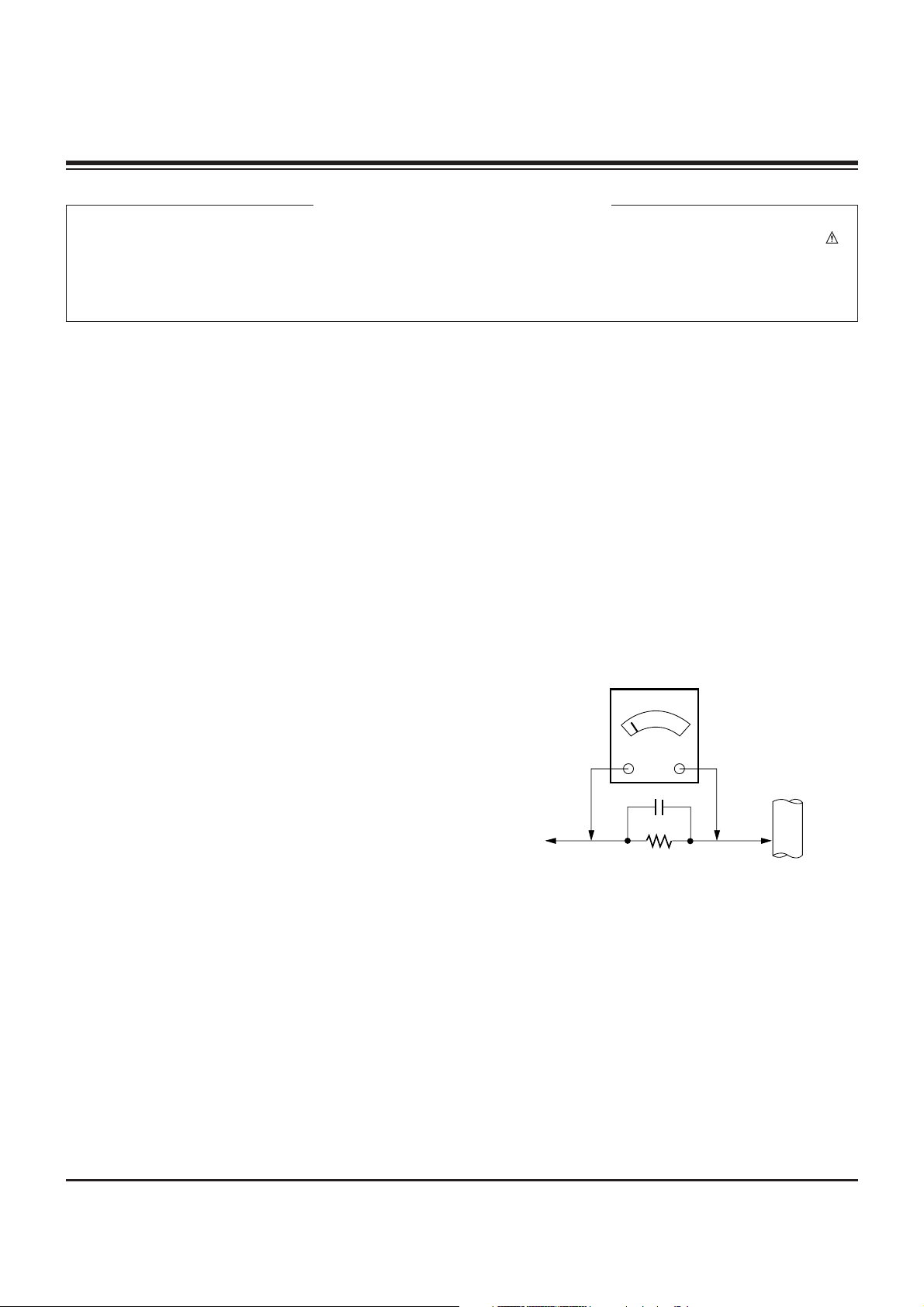
Leakage Current Hot Check (See below Figure)
Plug the AC cord directly into the AC outlet.
Do not use a line Isolation Transformer during this check.
Connect 1.5K/10watt resistor in parallel with a 0.15uF capacitor
between a known good earth ground (Water Pipe, Conduit, etc.)
and the exposed metallic parts.
Measure the AC voltage across the resistor using AC
voltmeter with 1000 ohms/volt or more sensitivity.
Reverse plug the AC cord into the AC outlet and repeat AC
voltage measurements for each esposed metallic part. Any
voltage measured must not exceed 0.75 volt RMS which is
corresponds to 0.5mA.
In case any measurement is out of the limits sepcified, there is
possibility of shock hazard and the set must be checked and
repaired before it is returned to the customer.
Leakage Current Hot Check circuit
CANADA: LG Electronics Canada, Inc. 550 Matheson
Boulevard East Mississauga, Ontario L4Z 4G3
USA : LG Customer Interactive Center
P.O.Box 240007, 201 James Record Road Huntsville,
AL 35824
Digital TV Hotline 1-800-243-0000
1.5 Kohm/10W
To Instrument's
exposed
METALLIC PARTS
Good Earth Ground
such as WATER PIPE,
CONDUIT etc.
AC Volt-meter
IMPORTANT SAFETY NOTICE
0.15uF
Page 3

- 3 -
SPECIFICATIONS.................................................................4
ADJUSTMENT INSTRUCTIONS ..........................................5
BLOCK DIAGRAM...............................................................11
EXPLODED VIEW...............................................................16
EXPLODED VIEW PARTS LIST .........................................17
REPLACEMENT PARTS LIST............................................18
SCHEMATIC DIAGRAM..........................................................
PRINTED CIRCUIT BOARDS.................................................
TABLE OF CONTENTS
Page 4
- 4 -
SPECIFICATIONS
The specifications shown above may be changed without prior notice for quality improvement.
Width x Height x Depth With Stand
(inches/mm)
Without Stand
Weight (pounds / kg) With Stand
Without Stand
Width x Height x Depth With Stand
(inches/mm)
Without Stand
Weight (pounds / kg) With Stand
Without Stand
Width x Height x Depth With Stand
(inches/mm)
Without Stand
Weight (pounds / kg) With Stand
Without Stand
32LB9D
( 32LB9D-UA)
47LC7DF
( 47LC7DF-UB)
1920 x 1080 (Dot) (Only 32LB9D model:1366 x 768 (Dot))
AC100-240V~ 50/60Hz
NTSC-M, ATSC, 64 & 256 QAM
VHF 2-13, UHF 14-69, CATV 1-135, DTV 2-69, CADTV 1-135
75 Ω
0 ~ 40°C
Less than 80%
-20 ~ 60°C
Less than 85%
60PY3D
( 60PY3DF-UA)
Resolution
Power requirement
Television System
Program Coverage
External Antenna Impedance
Operating Temperature Range
Operating Humidity Range
Storage Temperature Range
Storage Humidity Range
45.1x32.5x12.0 inches
1144.5x825.6x306.0 mm
45.1x29.7x4.1 inches
1144.5x754.5x103.0 mm
82.4 pounds / 37.5 kg
68.9 pounds / 31.3 kg
63.5x40.8x17.8 inches
1613.6x1036.8x452.0 mm
63.5x38.2x3.9 inches
1613.6x970.0x98.5 mm
180.1pounds / 81.7kg
144.8 pounds / 65.7kg
31.7x24.4x11.2 inches
805.8x619.7x283.9 mm
31.7x21.8x3.1 inches
805.8x554.1x79.0 mm
32.4 pounds / 14.7 kg
27.3 pounds / 12.4 kg
Page 5

1. Application Object
These instructions are applied to all of the PDP TV, PA73A.
2. Notes
(1) Because this is not a hot chassis, it is not necessary to use
an isolation transformer. However, the use of isolation
transformer will help protect test equipment.
(2) Adjustments must be done in the correct order.
(3) The adjustments must be performed in the circumstance of
25±5°C of temperature and 65±10% of relative humidity if
there is no specific designation.
(4) The input voltage of the receiver be must kept 110V, 60Hz
when adjusting.
(5) The receiver must be operational for about 15 minutes
prior to the adjustments.
3. Component 480i/1080p RGB
1080p Adjustment
3-1. Synopsis
Component 480i/1080p RGB 1080p adjustment to set the
black level and the Gain to optimum.
3-2. Test Equipment
(1) Service R/C
(2) 801GF(802B, 802F, 802R) or MSPG925FA Pattern
Generator (480i/1080i The Horizontal 100% Color Bar
Pattern adjust to within 0.7±0.1Vp-p)
[ Because the above pattern can differ by the model and
pattern for each device, you must check the pattern first.
3-3. 480i Comp1 Adjustment
(1) Receive the 480i Mode, 100% Horizontal Color Bar
Pattern(HozTV31Bar) to Component 1 port.
(MSPG-925FA: ==> Model : 209, Pattern : 65)
(2) Press the ADJ on the adjustment R/C to enter ‘Ez –
Adjust’. Select ‘1. Adjsut 480i Comp1’ using the
E
and
press the
G
to make the automatic adjustment.
(3) When the adjustment is over, 'ADC Component1 Success’
is displayed. If the adjustment has errors, 'ADC
Component1 408i Fail’ is displayed.
[Fail Message]
- If the component is not connected: Component1 Not
Connected
- If the input format is not 480i: Not Valid Format
- If the input signal is not generated: Check Signal Status
(4) Readjust after confirming the Pattern or adjustment
condition
(5) After adjustment is complete, exit the adjustment mode by
pressing the ADJ.
3-4. 1080p Comp1/RGB Adjustment
(1) Receive the 1080p Mode, 100% Horizontal Color Bar
Pattern(HozTV31Bar) to Component1 and RGB port.
(MSPG-925FA: ==> Model : 225 , Pattern : 65)
(2) After connecting, wait for the image displayed on the
screen
(3) Press the ADJ on the adjustment R/C to enter ‘Ez –
Adjust’. Select ‘2. Adjsut 1080p Comp1/RGB’ using the
E
and press the Gto make the automatic adjustment.
(4) When the adjustment is over, 'ADC Component1 Success’
is displayed. If the adjustment has errors, 'ADC
Component1 1080p Fail’ is displayed.
(5) When the Component1 adjustment is normally completed,
the RGB adjustment automatically starts.
(6) When the adjustment is over, 'ADC RGB 1080p Success’
is displayed.
(7) When the adjustment has errors, 'ADC RGB 1080p Fail’ is
displayed.
[Fail Message]
- If the component is not connected: Component1 Not
Connected
- If the input format is not 480i: Not Valid Format
- If the input signal is not generated: Check Signal Status
(8) Readjust after confirming the Pattern or adjustment
condition
(9) After adjustment is complete, exit the adjustment mode by
pressing the ADJ.
- 5 -
ADJUSTMENT INSTRUCTIONS
<Fig. 1> ADC Adjustment Pattern:
480i/1080i 60Hz HozTV31Bar Pattern
Page 6
- 6 -
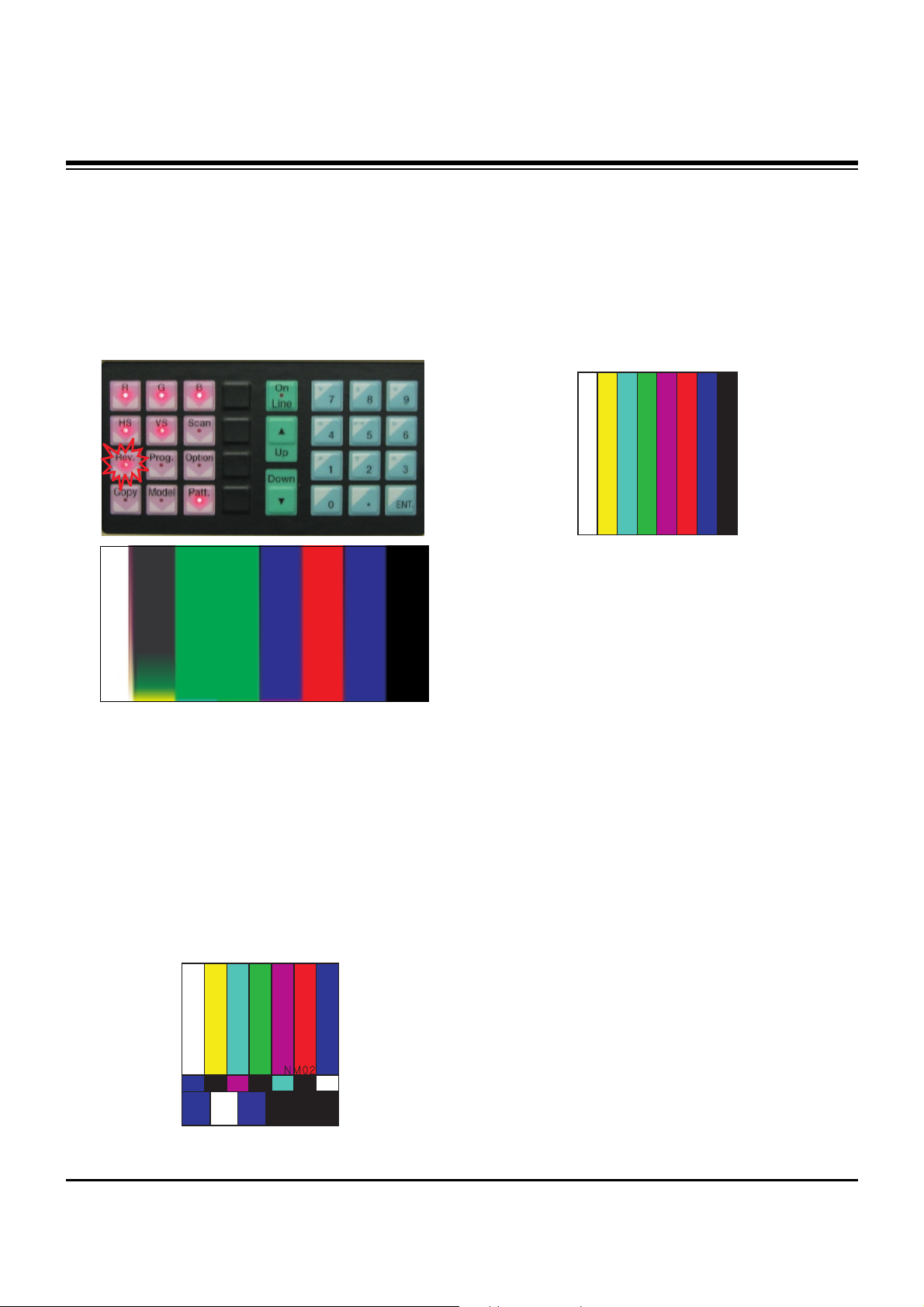
4. Auto Adjustment of RF and Video
Adjustment of RF and video signal
4-1. Adjustment
(1) Connect the Video Signal Generator (Master) to AV1 port
and input the signal.
Test Equipment: MSPG925FA Pattern Generator
(Model: 201(NTSC-M), Pattern: 33(100% color Bar))
At this time, press the Rev button certainly.
[ Because the above pattern can differ by the model, pattern
and rev button for each device, you must check the pattern
first.
(2) Apply the RF signal to the antenna. (Make sure that the
signal is received)
(3) Enter the ‘Ez - Adjust’ by pressing the ADJ on the Service
R/C.
After select the ‘3.Adjust RF and Video’, start the
adjustment by pressing the Right Key(
G
).
When it enters the adjustment mode, the screen is
automatically split as TV 2CH SPLIT as shown at the
below figure.
(4) When the adjustment is over, 'RF Configuration Success’ is
displayed. If the adjustment has errors, 'RF Configuration
Error’ is displayed.
(5) When adjusting the RF signal is completed, it is
automatically switched to the Video mode as shown at the
below figure, and the automatic adjustment for the Video
mode starts.
(6) When the adjustment is over, 'AV Configuration Success’ is
displayed. If the adjustment has errors, 'AV Configuration
Error’ is displayed.
ADJUSTMENT INSTRUCTIONS
<Fig. 2>
<Fig. 3>
<Fig. 4>
Page 7

- 7 -
ADJUSTMENT INSTRUCTIONS
<HEAT RUN>
O Preliminary action is applied to the test for afterimage
discharge detection, and 100% FULL WHITE PATTERN
must be operated automatically.
(1) Pressing Power On key on the adjustment R/C
(2) Full Test Pattern(2 min 30sec) --> Full Black
Pattern(30sec) --> Full White Pattern
(Full White Pattern when the main power is turned on
again after being turned off)
(3) Pattern Mode is deselected by pressing CH +/-, Exit Key.
[ Set is activated HEAT-RUN without signal generator in this
mode.
5. Voltage Adjustment(60” Model)
(1) Va Voltage Adjustment
1) Connect + terminal of D.M.M to Va pin of P805 and
connect – terminal to GND pin of P805.
2) Adjust RV501 voltage to match that of the label on the
Top/Right of the panel. (Deviation : ±0.5V)
(2) Vs Voltage Adjustment
1) Connect + terminal of D.M.M to Vs pin of P805 and
connect – terminal to GND pin of P805.
2) Adjust RV401 voltage to match that of the label on the
Top/Right of the panel. (Deviation : ±0.5V)
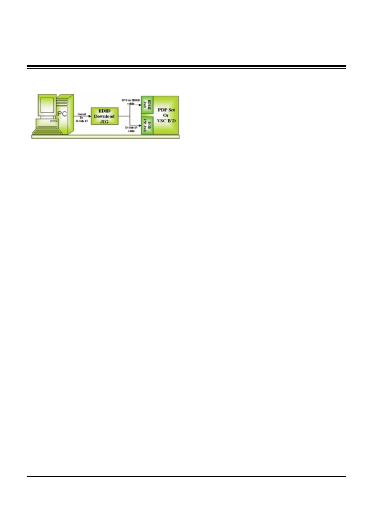
6. EDID(The Extended Display
Identification Data)/DDC
(Display Data Channel) Download
It is the feature to implement the “Plug and Play” which
automatically reconfigures the user’sl environment to directly
use by exchanging information without any command directly
to the PC or the monitor by the user, which is established by
the VESA
6-1. Required Test Equipment
(1) PC(S/W: EDID TESTER Ver.2.5)
(2) EDID Download JIG (PC serial to D-sub connection cable)
(3) Connection Cable
Test Pattern 2min 30sec
Test Pattern 30sec
If you turn on a still screen more than 20 minutes (Especially
Digital pattern(13 CH), Cross Hatch Pattern), an afterimage
may occur in the black level part of the screen.
Each PCB Assy must be checked by Check JIG Set before
assembly. (Especially, be careful Power PCB Assy which can
cause Damage to the PDP Module.)
Page 8
- 8 -
ADJUSTMENT INSTRUCTIONS
6-2. Setting of Device
6-3. EDID DATA for 60PY3DF
: EDID for HDMI-1 (DDC (Display Data Channel) Data)
EDID table =
0 1 2 3 4 5 6 7 8 9 A B C D E F
_________________________________________________
0 | 00 FF FF FF FF FF FF 00 1E 6D 01 00 01 01 01 01
10 | 00 11 01 03 80 73 41 96 0A CF 74 A3 57 4C B0 23
20 | 09 48 4C AF CF 00 31 40 45 40 61 40 81 80 A9 40
30 | 01 01 01 01 01 01 66 21 50 B0 51 00 1B 30 40 70
40 | 36 00 C4 8E 21 00 00 1E 02 3A 80 18 71 38 2D 40
50 | 58 2C 45 00 C4 8E 21 00 00 1E 00 00 00 FD 00 30
60 | 58 1F 64 11 00 0A 20 20 20 20 20 20 00 00 00 FC
70 | 00 4C 47 20 54 56 0A 20 20 20 20 20 20 20 01 8A
0 1 2 3 4 5 6 7 8 9 A B C D E F
_________________________________________________
0 | 02 03 16 F1 47 84 05 03 02 20 22 10 23 15 07 50
10 | 65 03 0C 00 10 00 01 1D 00 72 51 D0 1E 20 6E 28
20 | 55 00 C4 8E 21 00 00 1E 01 1D 80 18 71 1C 16 20
30 | 58 2C 25 00 C4 8E 21 00 00 9E 8C 0A D0 8A 20 E0
40 | 2D 10 10 3E 96 00 C4 8E 21 00 00 18 8C 0A D0 8A
50 | 20 E0 2D 10 10 3E 96 00 13 8E 21 00 00 18 26 36
60 | 80 A0 70 38 1F 40 30 20 25 00 C4 8E 21 00 00 1A
70 | 00 00 00 00 00 00 00 00 00 00 00 00 00 00 00 10
: EDID for HDMI-2 (DDC (Display Data Channel) Data)
EDID table =
0 1 2 3 4 5 6 7 8 9 A B C D E F
_________________________________________________
0 | 00 FF FF FF FF FF FF 00 1E 6D 01 00 01 01 01 01
10 | 00 11 01 03 80 73 41 96 0A CF 74 A3 57 4C B0 23
20 | 09 48 4C AF CF 00 31 40 45 40 61 40 81 80 A9 40
30 | 01 01 01 01 01 01 66 21 50 B0 51 00 1B 30 40 70
40 | 36 00 C4 8E 21 00 00 1E 02 3A 80 18 71 38 2D 40
50 | 58 2C 45 00 C4 8E 21 00 00 1E 00 00 00 FD 00 30
60 | 58 1F 64 11 00 0A 20 20 20 20 20 20 00 00 00 FC
70 | 00 4C 47 20 54 56 0A 20 20 20 20 20 20 20 01 8A
0 1 2 3 4 5 6 7 8 9 A B C D E F
________________________________________________
0 | 02 03 16 F1 47 84 05 03 02 20 22 10 23 15 07 50
10 | 65 03 0C 00 20 00 01 1D 00 72 51 D0 1E 20 6E 28
20 | 55 00 C4 8E 21 00 00 1E 01 1D 80 18 71 1C 16 20
30 | 58 2C 25 00 C4 8E 21 00 00 9E 8C 0A D0 8A 20 E0
40 | 2D 10 10 3E 96 00 C4 8E 21 00 00 18 8C 0A D0 8A
50 | 20 E0 2D 10 10 3E 96 00 13 8E 21 00 00 18 26 36
60 | 80 A0 70 38 1F 40 30 20 25 00 C4 8E 21 00 00 1A
70 | 00 00 00 00 00 00 00 00 00 00 00 00 00 00 00 00
: EDID for HDMI-3 (DDC (Display Data Channel) Data)
EDID table =
0 1 2 3 4 5 6 7 8 9 A B C D E F
__________________________________________________
0 | 00 FF FF FF FF FF FF 00 1E 6D 01 00 01 01 01 01
10 | 00 11 01 03 80 73 41 96 0A CF 74 A3 57 4C B0 23
20 | 09 48 4C AF CF 00 31 40 45 40 61 40 81 80 A9 40
30 | 01 01 01 01 01 01 66 21 50 B0 51 00 1B 30 40 70
40 | 36 00 C4 8E 21 00 00 1E 02 3A 80 18 71 38 2D 40
50 | 58 2C 45 00 C4 8E 21 00 00 1E 00 00 00 FD 00 30
60 | 58 1F 64 11 00 0A 20 20 20 20 20 20 00 00 00 FC
70 | 00 4C 47 20 54 56 0A 20 20 20 20 20 20 20 01 8A
0 1 2 3 4 5 6 7 8 9 A B C D E F
_________________________________________________
0 | 02 03 16 F1 47 84 05 03 02 20 22 10 23 15 07 50
10 | 65 03 0C 00 30 00 01 1D 00 72 51 D0 1E 20 6E 28
20 | 55 00 C4 8E 21 00 00 1E 01 1D 80 18 71 1C 16 20
30 | 58 2C 25 00 C4 8E 21 00 00 9E 8C 0A D0 8A 20 E0
40 | 2D 10 10 3E 96 00 C4 8E 21 00 00 18 8C 0A D0 8A
50 | 20 E0 2D 10 10 3E 96 00 13 8E 21 00 00 18 26 36
60 | 80 A0 70 38 1F 40 30 20 25 00 C4 8E 21 00 00 1A
70 | 00 00 00 00 00 00 00 00 00 00 00 00 00 00 00 F0
: EDID DATA for RGB
EDID table =
0 1 2 3 4 5 6 7 8 9 A B C D E F
________________________________________________
0 | 00 FF FF FF FF FF FF 00 1E 6D 01 00 01 01 01 01
10 | 00 11 01 03 18 73 41 96 0A CF 74 A3 57 4C B0 23
20 | 09 48 4C AF CF 00 31 40 45 40 61 40 81 80 A9 40
30 | 01 01 01 01 01 01 66 21 50 B0 51 00 1B 30 40 70
40 | 36 00 C4 8E 21 00 00 1A 02 3A 80 18 71 38 2D 40
50 | 58 2C 45 00 C4 8E 21 00 00 1E 00 00 00 FD 00 30
60 | 58 1F 64 11 00 0A 20 20 20 20 20 20 00 00 00 FC
70 | 00 4C 47 20 54 56 0A 20 20 20 20 20 20 20 01 F6
Page 9

- 9 -
ADJUSTMENT INSTRUCTIONS
0 1 2 3 4 5 6 7 8 9 A B C D E F
__________________________________________________
0 | 02 03 04 00 0E 1F 00 80 51 00 1E 30 40 80 37 00
10 | C4 8E 21 00 00 1C F1 27 00 A0 51 00 25 30 50 80
20 | 37 00 C4 8E 21 00 00 1C 26 36 80 A0 70 38 1F 40
30 | 30 20 25 00 C4 8E 21 00 00 0A 00 00 00 00 00 00
40 | 00 00 00 00 00 00 00 00 00 00 00 00 00 00 00 00
50 | 00 00 00 00 00 00 00 00 00 00 00 00 00 00 00 00
60 | 00 00 00 00 00 00 00 00 00 00 00 00 00 00 00 00
70 | 00 00 00 00 00 00 00 00 00 00 00 00 00 00 00 BC
7. Adjustment of White Balance
7-1. Required Test Equipment
(1) Color Analyzer : CA-210 (CH 9)
=> To adjust color temperature of LCD, CS-1000 is the
Color Analyzer(CA-210) and should be set to use CH 9
in which white, red, green, and blue color are corrected.
Conduct the adjustment according to the coordinates for
White Balance adjustment in the table below.
(2) Computer for adjusting (necessary for the automatic
adjustment, possible to communicate with the RS-232C,
Baud Rate : 115200)
(3) Video Signal Generator MSPG-925F 720p, 216Gray
(Model :217, Pattern 78)
7-2. Connection Diagram of Equipment
for Measuring
(Automatic Adjustment)
Use the internal pattern to adjust White Balance. The pattern
is automatically given when the automatic adjustment device
is connected or when a user presses ADJ on the remote
controller to start Ez Adjust and then selects 6.White-Balance.
7-3. White Balance Adjustment Method
Basically it uses the internal pattern but when internal pattern
is not possible, you can select HDMI input for adjustment.
Through the option at the most bottom part of the Ez Adjust
Menu 7.White Balance menu, you can select NONE, INNER
and HDMI, and the default is set to INNER. When the
adjustment cannot be done with the internal pattern, you can
select HDMI input for adjustment.
For manual adjustment, press the ADJ KEY of the adjustment
R/C to enter Ez Adjust 7.White-Balance, and the pattern is
automatically displayed. (When you set the Option to INNER,
the default is always set to INNER)
(1) Connect the set according to the internal pattern or HDMI
input in accordance with measuring device connection
diagram.
(2) Set the Baud Rate of RS-232C to 115200. It is set to
115200 as default.
(3) Connect the RS-232C Cable to the set.
(4) Connect the HDMI Cable to the set. (Limited to the set with
HDMI option)
(5) Select and adjust the model applicable to PA73A chassis
from the adjuster.
7-4. Automatic Adjustment
(1) Execute POWER ON(Â) of the adjustment R/C to execute
automatic adjustment or set the Baud Rate to 115200.
(2) Always start adjustment with “wb 00 00” and end
adjustment with “wb 00 ff” (Adjust the offset if necessary)
(3) RS-232C command used for the automatic adjustment
Ex) Wb 00 00-----white balance Automatic Adjustment Start
Wb 00 10-----Gain Adjustment start (Internal pattern)
Ja 00 ff------Adjustment Data
Jb 00 c0
...
...
Wb 00 1f-----Gain Adjustment End
*(wb 00 20(Start), wb 00 2f(End))----- When adjust Off-set
Wb 00 ff------White Balance Automatic Adjustment End
(Disappear Inside pattern)
(internal pattern)
Connection Diagram for Internal Pattern
Connection Diagram for HDMI Input
wb
wb
wb
wb
wb
wb
00
00
00
00
00
00
00
10
1f
20
2f
ff
White Balance Adjustment Start
Gain Adjustment Start(Internal white pattern)
Gain Adjustment End
Offset Adjustment Start(Internal white pattern)
Offset Adjustment End
White Balance Adjustment End
(Disappear Internal pattern)
RS-232C COMMAND
[CMD ID DATA]
Meaning
Page 10
- 10 -
ADJUSTMENT INSTRUCTIONS
(4) Adjustment Map
7-5. Manual Adjustment
(1) Required Test Equipment: CA-100
(2) Enter the ‘Ez - Adjust’ by pressing the ADJ on the Service
R/C.
(3) Select 9.TEST PATTERN using the CH + / - KEY and
press the Enter KEY to execute a heat run for more than
30 minutes.
(4) Zero Calibrate of the Color Analyzer, then attach sensor to
PDP module surface when you adjust.
(5) Select ‘6. White-Balance’ of ‘Ez - Adjust’ by pressing the
ADJ KEY on the Service R/C. Then enter adjustment mode
by pressing the Right KEY (
G
) .
(The internal pattern of full white appears by pressing
G
)
(6) The adjustment is conducted in three levels of color
temperature; COOL, MEDIUM, and WARM.
1) For all color temperatures, fix R-Cut / G-Cut / B-Cut to
64.
2) Color Temperature: Cool, Medium, Warm
Adjust the High Light by using the G Gain / R Gain.
R, G, B Gain does not go over 192.
Full White 216gray
[Cool]
X; 0.276±0.002 Y; 0.283±0.002
Color temperature: 11000°K
dUV: -3dUV
[Medium]
X; 0.285±0.002 Y; 0.293±0.002
Color temperature: 9300°K
dUV: -3dUV
[Warm]
X; 0.313±0.002 Y; 0.329±0.002
Color temperature: 6500°K
dUV: -3dUV
R Gain
G Gain
B Gain
R Cut
G Cut
B Cut
Jg
Jh
Ji
Cool
Ja
Jb
Jc
Mid
RS-232C COMMAND
[CMD ID DATA]
CENTER
(DEFAULT)(Decimal)
Jd
Je
Jf
00
00
00
255
255
255
127
127
127
Warm
Min
Max
(Deci
mal)
184
189
192
64
64
64
Cool
192
184
161
64
64
64
Mid
192
150
84
64
64
64
Warm
Page 11
- 11 -
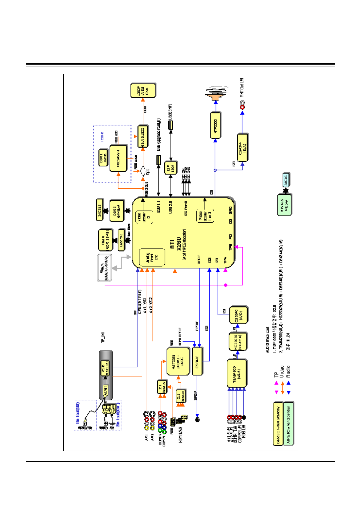
BLOCK DIAGRAM
Page 12
- 12 -
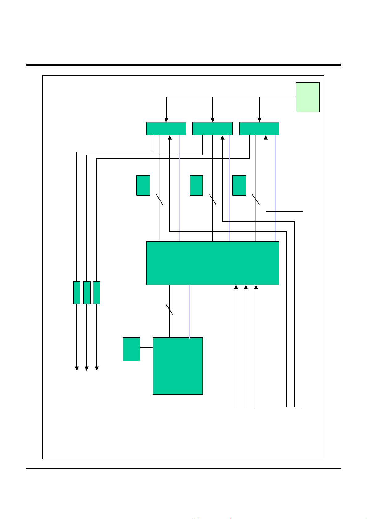
BLOCK DIAGRAM
ddc1
hpd1ddc
ddc2
ddc3
hpd2
hpd3
5v1
5v2
5v3
hdmi1
hdmi2
hdmi3
detect1
detect2
detect3
To cpu
mst3361
sel1
sel2
sel3
From
cpu
MST3361 + TMDS341AFPC , 3 port HDMI (HPD Control)
Hdmi_sig1
Hdmi_sig2
Hdmi_sig3
EDID1
HDCP
rom
EDID2
EDID1
Hdmi_sig
TMDS341
hpd1
hpd2
hpd3
Micom
CEC
CEC
CEC
Page 13

- 13 -
BLOCK DIAGRAM
ATI
(X260)
I2C Master
AT/NT Tuner
0xC2
HDMI
ADC
(MST3361)
0X9C
Temp.
Sensor
(LM75)
0X94
U-Com
(MTV416)
0x50
I2C_CH1 (+3.3V_L & +5V_L)
I2C_CH2 (+3.3V_L & +5V_L)
I2C_CH3 (+3.3V_L)
Port
Expander
(M62320)
0X74
Audio
Switch
(TEA6420)
0X9A
DASP
(NTP3000)
0X54
PDP Module
0x1C
VSB/QAM
(LGDT3703)
Main
0X1C
Live
Dead
CS8416A
0X20(W)
0X21(R)
EEPROM
(24LC512)
0xA6
CH1
CH2
CH3
FRC94XYH
0x94
EEPROM
(24LC16)
5V
5V
5V
2.5V
IIC channel map
Page 14

- 14 -
BLOCK DIAGRAM
+12.0V
+12.0V
+6.0V
+6.0V
CS4344
CS4344
CS5340
CS5340
PQ05DZ1U
PQ05DZ1U
KIA78R09
KIA78R09
FAN1
FAN1
KIA78R09
KIA78R09
FAN2, 3
FAN2, 3
MC33078
MC33078
X260
X260
HYB18T512(4EA)
HYB18T512(4EA)
AZ1117H-1.8
AZ1117H-1.8
LM75
LM75
ICL3232CBNZ
ICL3232CBNZ
+5.0VST
+5.0VST
+3.3V_L
+3.3V_L
AT/NT Tuner
AT/NT Tuner
+5V_L
+5.0V
SI3865
SI3865
PQ05DZ1U
PQ05DZ1U
Live Power
Dead Power
Live-on
AZ1117H-3.3
AZ1117H-3.3
LGDT3703(MAIN)
LGDT3703(MAIN)
SC1565-1.8
SC1565-1.8
ISL6549CB
ISL6549CB
1.2V
1.8V
ISL6549CB
ISL6549CB
1.8V
MK3727D
MK3727D
74LVT16373(2EA)
74LVT16373(2EA)
S29GL256
S29GL256
THC63LVD1023
THC63LVD1023
+3.3V_L
HYB18T512(4EA)
HYB18T512(4EA)
MK3727D
MK3727D
+19.0V
+19.0V
NTP3000
NTP3000
NTP3000
NTP3000
1.8V
BA033FP-3.3
BA033FP-3.3
MTV416
MTV416
AZ1086-1.8
AZ1086-1.8
AZ1117H-3.3
AZ1117H-3.3
SC1565-2.5
SC1565-2.5
MST3369
MST3369
9.0V
TEA6420
TEA6420
9.0V
CS8416
CS8416
KIA78R09
KIA78R09
MK3727D
MK3727D
MIC2505
MIC2505
3.3VST_MICOM
24C08
24C08
FRC94XYH
FRC94XYH
Live-on
24C512
24C512
STMAV335
STMAV335
ISP1504
ISP1504
MIC2505
MIC2505
KIA7805
KIA7805
AZ1085S-3.3
AZ1085S-3.3
AZ1085S-1.8
AZ1085S-1.8
24C16
24C16
FRC
FRC
SC1565-2.6
SC1565-2.6
MIC3910-2.5
MIC3910-2.5
SC1592-1.0
SC1592-1.0
12.0V
HY5DU281622
HY5DU281622
SC2595-1.0
SC2595-1.0
Power Block
Page 15

- 15 -
NOTES
Page 16

- 16 -
EXPLODED VIEW
400
240
102
101
103
602
600
303
304
306
307
121
300
302
301
305
120
603
601
580
581
582
260
250
208
201
202
203
204
204
200
205
206
209
207
205
206
207
560
570
540
542
541
502
520
501
590
A21
A2
901
900
Page 17

- 17 -
EXPLODED VIEW PARTS LIST
101 EAL30846301 Fan Module,G6015S12b2 1.8KRPM DC 12V 840MA 12W 60HZ 200MM3
102 MJH32511701 Supporter,PRESS EGI 0.6 NON EGI FAN_SUPP
103 AJJ31606802 Supporter Assembly,60PY30, SKD, FAN SUPPORTER ASSY
AJJ31606801 Supporter Assembly,60PY30, FAN SUPPORTER ASSY
120 EAB33735401 Speaker Assembly,50PY3 SLIM SPEAKER ASSY RIGHT
121 EAB33735402 Speaker Assembly,50PY3 SLIM SPEAKER LEFT ASSY
200 EAJ32791801 PDP,Module-FullHD PDP60H10000.ADLGB FULLHD 60INCH 1920X1080 16/9 PDP DIVISION
EAJ32791701 PDP,Module-FullHD PDP60H10000.AKLGG FULLHD 60INCH
201 EBR32922301 PCB Assembly,EBR32922301 CTRL ASS’Y 60 H1 Full-HD CTRL PDP DIVISION
202 EBR32015901 PCB Assembly,EBR32015901 YDRV ASS’Y 60 H1 Full-HD YDRV TOP PDP DIVISION
203 EBR32016101 PCB Assembly,EBR32016101 YDRV ASS’Y 60 H1 Full-HD YDRV BOTTOM PDP DIVISION
204 EBR32003901 PCB Assembly,EBR32003901 XRLB ASSY 60 H1 Full-HD XLB & XRT PDP DIVISION
205 EBR32004501 PCB Assembly,EBR32004501 XRCLBT ASSY’ 60 H1 Full-HD XCLB & XCRT PDP DIVISION
206 EBR32004601 PCB Assembly,EBR32004601 XRCRBT ASSY’ 60 H1 Full-HD XCRB & XCLT PDP DIVISION
207 EBR32004701 PCB Assembly,EBR32004701 XRRB ASSY 60 H1 Full-HD XRB & XLT PDP DIVISION
208 EBR32324201 PCB Assembly,EBR32324201 YSUS ASS’Y 60 H1 Full HD PDP DIVISION
209 EBR32324301 PCB Assembly,EBR32324301 ZSUS ASS’Y 60 H1 Full HD PDP DIVISION
240 AJJ30996203 Supporter Assembly,60PY30, SKD, Vertical Supporter Right Assy.
AJJ30996201 Supporter Assembly,60PY30, Vertical Supporter Right Assy
250 AJJ30996204 Supporter Assembly,60PY30, SKD, Vertical Supporter Left Assy.
AJJ30996202 Supporter Assembly,60PY30, Vertical Supporter Left Assy.
260 AJJ31606903 Supporter Assembly,60PY30, MODULE SUPP_SIDE HOR.+ SUPP_SIDE. PANTON ASSY
AJJ31606902 Supporter Assembly,60PY30, MODULE SUPP_SIDE HOR.+ SUPP_SIDE, Press
300 ABJ30995004 Cabinet Assembly,60PY3DR-UA PA71A 60 LG, C/SKD
ABJ30995002 Cabinet Assembly,60PY3DR-UA PA71A 60 LG
301 ADV31660202 Frame Assembly,60py30 mf-056l 60 frame assy, LG
302 MBH32314201 Cabinet,MOLD ABS 60PY30 ABS E3, Cabinet, XCANVAS
303 AJJ30996402 Supporter Assembly,60PY30, Filter Supporter Top, SKD
AJJ30996401 Supporter Assembly,60PY30, Filter Supporter Top
304 AJJ30996502 Supporter Assembly,60PY30, Filter Supporter Bottom Assy C/SKD
AJJ30996501 Supporter Assembly,60PY30, Filter Supporter Bottom Assy
305 5230V00018B Filter,CUTTING ACRYL TOP 60PY2DR ø‹ 60inch PDP MITSUI 60 GLASS FILTER
306 AJJ30996603 Supporter Assembly,60PY30, SKD, Filter Supporter Right Assy
AJJ30996601 Supporter Assembly,60PY30, Filter Supporter Right Assy
307 AJJ30996703 Supporter Assembly,60PY3, SKD, Filter Supporter Left Assy
AJJ30996701 Supporter Assembly,60PY30, Filter Supporter Left Assy
400 ACQ30995608 Cover Assembly,Rear 60PY3DF-ZA PD75A 60 Back Cover Assy, SKD, Without DVR & Without Woofer
ACQ30995604 Cover Assembly,Rear 60PY3D PA71A 60 Back Cover Assy, Without DVR & Without Woofer
501 AGU31681105 Plate Assembly,PLATE TUNER BOT SMALL, 60PY3DF-UA(E3)
502 AGU31680911 Plate Assembly,PLATE TUNER COVER SMALL, 60PY3 E3 /AMERICA
520 EBR36117301 PCB Assembly,Main PA73A 60PY3DF-UA AUSLLHX 60PY3DF-UA MAIN MANUAL ASSY
540 EAJ33837501 VFD,16SL02HS1 237
541 ABA32560202 Bracket Assembly,BRACKET 60PY3DF-ZA PD75A VFD BRACKET ASSY, CSKD
ABA32560201 Bracket Assembly,BRACKET 60PY3DF-ZA PD75A VFD BRACKET ASSY
542 EBT34918701 Chassis Assembly,SUB PA71A 60PY3DR VFD ASSY.
560 EBR36865501 PCB Assembly,Audio BUZZER ASSEMBLY SOUND S.T PDP 50PB3,60PY3 PDP BUZZER B/D YANG WOO CO
570 EBR33918301 PCB Assembly,SUB M.I PA71A 50PB3DR KOREA 50PB3DR PRE AMP
580 EAY32929201 SMPS,AC/DC 1H391W 100VTO240V 800W 50 TO 60HZ UL/CE/TUV 60INCH PDP FULL HD
581 EAY32929401 SMPS,AC/DC 1H391W-PFC 100VTO240V 800W 50 TO 60HZ UL/CE/TUV 60INCH PDP FULL HD
582 EAY32929901 SMPS,AC/DC 1H391W-ACIN 100VTO240V 800W 50 TO 60HZ UL/CE/TUV 60INCH PDP FULL HD
590 EAM35012702 Filter,AC Line IF2-N10CEWL1 1.1mH 250VAC 10A 0.22uF 1000pF
600 EBT36207701 Chassis Assembly,SUB PA73A SUB PA73A 60PY3DF-UB SIDE AV ASSY
601 EBR35103101 PCB Assembly,SUB M.I PA71A SIDE A/V
602 ABA30998703 Bracket Assembly,AV PY30 AB E3_SIDE AV BRACKET ASSY, USA,With USB
603 MGJ32323501 Plate,Shield PRESS AL 1.0 SHIELD AL E3 PY30 SHIELD,SIDE AV
900 AAN30997003 Base Assembly,STAND 60PY3 PA64F Stand Assy, SKD
AAN30997001 Base Assembly,STAND 60PY30 PA64F Stand Assy,
901 MCK32693801 Cover,MOLD ABS 60PY3 ABS COVER CABLE
A2 6710900011Z Remote Controller,COMPLEX LA73A 42LB5DF-UA USA_Full HD_NON DVR
A21 3550V00684B Cover,BATTERY BACK ABS, HF-380 BK
No.
Part No.
Description
Page 18

- 18 -
REPLACEMENT PARTS LIST
LOCA. NO PART NO DESCRIPTION
Q300
Q301
Q302
Q303
Q304
Q305
Q306
Q307
Q308
Q309
Q310
Q311
Q312
Q313
Q314
Q315
Q316
Q317
Q318
Q319
Q400
Q401
Q402
Q403
Q404
Q405
Q406
Q407
Q409
Q410
Q411
Q500
Q501
Q503
Q504
Q505
Q506
Q508
Q510
Q511
Q512
Q513
Q514
Q515
Q516
Q601
EBK32756101
EBK32756101
0TR387500AA
0TR387500AA
0TR387500AA
0TR387500AA
0TR387500AA
0TR387500AA
0TR387500AA
0TR387500AA
0TR387500AA
0TR387500AA
0TR387500AA
0TR387500AA
0TR387500AA
EBK32756101
0TFDI80001B
0TFDI80001B
0TFDI80001B
0TFDI80001B
0TR387500AA
0TR104009AF
0TR104009AF
0TR387500AA
0TR387500AA
0TR104009AF
0TR104009AF
0TFDI80001B
0TR104009AF
0TR104009AF
0TR387500AA
0TR387500AA
0TR387500AA
0TFDI80001B
0TFDI80001B
0TR387500AA
0TR387500AA
0TR150400BA
0TR150400BA
0TR387500AA
0TR387500AA
0TR102009AM
0TFDI80001B
0TFDI80001B
0TFDI80001B
0TR150400BA
FET,Si4800BDY N-CHANNEL M
FET,Si4800BDY N-CHANNEL M
2SC3875S(ALY) NPN 5V
2SC3875S(ALY) NPN 5V
2SC3875S(ALY) NPN 5V
2SC3875S(ALY) NPN 5V
2SC3875S(ALY) NPN 5V
2SC3875S(ALY) NPN 5V
2SC3875S(ALY) NPN 5V
2SC3875S(ALY) NPN 5V
2SC3875S(ALY) NPN 5V
2SC3875S(ALY) NPN 5V
2SC3875S(ALY) NPN 5V
2SC3875S(ALY) NPN 5V
2SC3875S(ALY) NPN 5V
FET,Si4800BDY N-CHANNEL M
FET,2N7002(F) N-CHANNEL D
FET,2N7002(F) N-CHANNEL D
FET,2N7002(F) N-CHANNEL D
FET,2N7002(F) N-CHANNEL D
2SC3875S(ALY) NPN 5V
KRC104S NPN 40V
KRC104S NPN 40V
2SC3875S(ALY) NPN 5V
2SC3875S(ALY) NPN 5V
KRC104S NPN 40V
KRC104S NPN 40V
FET,2N7002(F) N-CHANNEL D
KRC104S NPN 40V
KRC104S NPN 40V
2SC3875S(ALY) NPN 5V
2SC3875S(ALY) NPN 5V
2SC3875S(ALY) NPN 5V
FET,2N7002(F) N-CHANNEL D
FET,2N7002(F) N-CHANNEL D
2SC3875S(ALY) NPN 5V
2SC3875S(ALY) NPN 5V
2SA1504S(ASY) PNP -5V
2SA1504S(ASY) PNP -5V
2SC3875S(ALY) NPN 5V
2SC3875S(ALY) NPN 5V
KRA102S PNP -30V 0V FET,2N7002(F) N-CHANNEL D
FET,2N7002(F) N-CHANNEL D
FET,2N7002(F) N-CHANNEL D
2SA1504S(ASY) PNP -5V
LOCA. NO PART NO DESCRIPTION
IC101
IC200
IC201
IC202
IC203
IC206
IC207
IC208
IC300
IC301
IC302
IC303
IC304
IC305
IC306
IC307
IC308
IC310
IC400
IC401
IC402
IC403
IC404
IC405
IC406
IC407
IC408
IC409
IC501
IC505
IC507
IC508
IC600
IC601
IC602
IC603
IC604
IC605
IC605
IC700
IC704
IC705
IC707
IC708
IC711
IC712
EAN32808701
EAN33624401
EAN33931901
EAN33931901
EAN33624401
EAN33624401
0IMCRAL021A
EAN33624401
0IKE702900G
0IMCRSJ001B
0IPMG00049A
0IPMG00049A
EAN33573001
0ISTLPH026A
0IPRP00009A
0IKE702900G
0IPMGA0010A
0IMCRAL006A
0IMCRSJ001B
0IPMGA0010A
0IPRP00696C
EAN32724701
0IMMRCS012B
0IMMRAL014D
0IMMRAL014D
0IMMRAL014D
0IMMRAL014D
EAN35942401
0IPRPCI017A
EAN32404601
0IPMG00049A
0IMCRMN028C
0IPMGKE030A
EAN32174001
0IPMGSH019A
0IPMGA0010A
0ICTMLG019A
0IPMG00049A
0IPMGSH019A
EAN32662801
0IPMGKE030A
0IMI623200B
0IPMGKE032A
0IPMGKE032A
0IPMGKE030A
EAN32013101
XILLEON260 500MVTO2.1V,35
HYB18TC512160BF-3S 512MBI
TC74LCX16373AFT 2V~3.6V 5
TC74LCX16373AFT 2V~3.6V 5
HYB18TC512160BF-3S 512MBI
HYB18TC512160BF-3S 512MBI
AT24C512W-10SU-2.7 512KBI
HYB18TC512160BF-3S 512MBI
KIA7029AF - 3TO15V 2.9V
SC1565IST-2.5TR 2.2TO5V 2
AZ1117H-1.8TR/E1[H13A] 3.
AZ1117H-1.8TR/E1[H13A] 3.
SC2621ASTRT 18V 5V~17.4
74LVC14APW 1.2TO3.6V 01
ICL3232CBNZ 3VTO5.5V - SS
KIA7029AF - 3TO15V 2.9V
AZ1117H-3.3 4.75TO10V 3.3
AT24C16AN-10SU-2.7 16KBIT
SC1565IST-2.5TR 2.2TO5V 2
AZ1117H-3.3 4.75TO10V 3.3
MST3361M-LF-170 3.3V_2.5V
STMAV335 4.0TO5.5V 5NSEC
CAT24WC08W-T(MST3000) 8KB
AT24C02BN-10SU-1.8 2KBIT
AT24C02BN-10SU-1.8 2KBIT
AT24C02BN-10SU-1.8 2KBIT
AT24C02BN-10SU-1.8 2KBIT
TMDS341APFCR 3TO3.6V 10NS
CS8416-CZZR 3.13VTO3.46V,
NTP3000 7TO30V 5.5V 01%
AZ1117H-1.8TR/E1[H13A] 3.
MSP4450K-QA-D6 7.6TO8.7V_
KIA78R05F 6TO12V 5V 8W DP
THC63LVD1023 3.0VTO3.6V 1
PQ018EZ02ZPH(PB-FREE) 2.3
AZ1117H-3.3 4.75TO10V 3.3
LGDT3303 3TO5 25m 16M TQF
AZ1117H-1.8TR/E1[H13A] 3.
PQ018EZ02ZPH(PB-FREE) 2.3
KA7809ERTM 35V to 40V 9V
KIA78R05F 6TO12V 5V 8W DP
M62320FP(SOP) 4.5TO5.5V 0
KIA78R09F 10TO25V 9V 8W D
KIA78R09F 10TO25V 9V 8W D
KIA78R05F 6TO12V 5V 8W DP
MIC2505-2YM 2.7V TO 7.5V
IC
RUN DATE : 2007.5.3
TRANSISTOR
Page 19

- 19 -
LOCA. NO PART NO DESCRIPTION
Q602
Q602
Q603
Q603
Q611
Q702
D300
D301
D302
D303
D304
D402
D404
D408
ZD405
ZD406
ZD407
ZD408
ZD409
ZD415
ZD416
ZD417
ZD418
ZD419
ZD420
ZD421
ZD501
ZD502
ZD700
ZD705
ZD710
ZD711
ZD712
C1
C1
C2
C200
C201
C202
C203
C204
C205
C206
C207
C208
C209
C210
0TFDI80001B
0TFDI80001B
0TFDI80001B
0TFDI80001B
0TR387500AA
0TFVI80067A
0DSGD00038A
0DRSE00038A
0DRSE00038A
0DD184009AA
0DD184009AA
0DD184009AA
0DD184009AA
0DD184009AA
0DZ360009EB
0DZ360009EB
0DZ560009DA
0DZ560009DA
0DZ560009DA
0DZ360009EB
0DZ560009DA
0DZ560009DA
0DZ560009DA
0DZ560009DA
EAH33945901
EAH33945901
0DZ560009DA
0DZRM00248A
0DZ360009EB
0DZ360009EB
0DZ560009DA
0DZ360009EB
0DZ360009EB
0CE477DD618
0CE4763F618
0CH3104K566
0CK104BF56A
EAE33970001
0CK104BF56A
0CK104BF56A
0CK104BF56A
EAE33970001
0CK104BF56A
EAE33970001
0CK104BF56A
0CK104BF56A
0CK104BF56A
FET,2N7002(F) N-CHANNEL D
FET,2N7002(F) N-CHANNEL D
FET,2N7002(F) N-CHANNEL D
FET,2N7002(F) N-CHANNEL D
2SC3875S(ALY) NPN 5V
FET,SI3865BDV(E3) N-CHANN
1N4148W 1.25V 100V 150MA 2A
SDC15 1.3V 14.3VTO16.4V 21.
SDC15 1.3V 14.3VTO16.4V 21.
KDS184 KDS184 TP KEC - 85V
KDS184 KDS184 TP KEC - 85V
KDS184 KDS184 TP KEC - 85V
KDS184 KDS184 TP KEC - 85V
KDS184 KDS184 TP KEC - 85V
Zener,UDZS3.6B 3.6V 3.6TO3.845V 1
Zener,UDZS3.6B 3.6V 3.6TO3.845V 1
Zener,UDZS5.6B 5.6V 5.49TO5.73V 6
Zener,UDZS5.6B 5.6V 5.49TO5.73V 6
Zener,UDZS5.6B 5.6V 5.49TO5.73V 6
Zener,UDZS3.6B 3.6V 3.6TO3.845V 1
Zener,UDZS5.6B 5.6V 5.49TO5.73V 6
Zener,UDZS5.6B 5.6V 5.49TO5.73V 6
Zener,UDZS5.6B 5.6V 5.49TO5.73V 6
Zener,UDZS5.6B 5.6V 5.49TO5.73V 6
CDS3C30GTH 3V 120V 1.9
CDS3C30GTH 3V 120V 1.9
Zener,UDZS5.6B 5.6V 5.49TO5.73V 6
Zener,RLZ8.2B 8.2V 7.78TO8.19V 8O
Zener,UDZS3.6B 3.6V 3.6TO3.845V 1
Zener,UDZS3.6B 3.6V 3.6TO3.845V 1
Zener,UDZS5.6B 5.6V 5.49TO5.73V 6
Zener,UDZS3.6B 3.6V 3.6TO3.845V 1
Zener,UDZS3.6B 3.6V 3.6TO3.845V 1
EGR477M010T6G1G11G 470uF 20%
ESF476M016T1A5E05G 47uF 20% 1
0805B104K500CT 100nF 10% 50V
C1005X7R104KET 100nF 10% 16V
CS1005X5R105K6R3NR 1uF 10% 6.
C1005X7R104KET 100nF 10% 16V
C1005X7R104KET 100nF 10% 16V
C1005X7R104KET 100nF 10% 16V
CS1005X5R105K6R3NR 1uF 10% 6.
C1005X7R104KET 100nF 10% 16V
CS1005X5R105K6R3NR 1uF 10% 6.
C1005X7R104KET 100nF 10% 16V
C1005X7R104KET 100nF 10% 16V
C1005X7R104KET 100nF 10% 16V
LOCA. NO PART NO DESCRIPTION
C211
C2114
C2115
C2116
C2117
C2119
C212
C2120
C2122
C2124
C2126
C2127
C2127
C2128
C213
C2130
C2131
C2132
C2133
C2134
C2136
C2137
C2138
C2139
C214
C2140
C2141
C2142
C2143
C2144
C2145
C2146
C2147
C2148
C2149
C215
C2150
C2151
C2152
C2153
C2154
C2155
C2156
C2157
C2158
C2159
C216
C2160
C2161
C2162
C2163
EAE33970001
0CK104BF56A
0CK104BF56A
0CK104BF56A
0CK104BF56A
0CK104BF56A
0CK104BF56A
0CK104BF56A
0CK104BF56A
0CK106EF56A
0CC150BK4AA
0CC150BK4AA
0CZZB00035A
0CK102BK56A
0CK104BF56A
0CK104BF56A
0CK106EF56A
0CK104BF56A
0CK106EF56A
0CK104BF56A
0CK106EF56A
0CK104BF56A
0CK104BF56A
0CK104BF56A
EAE33970001
0CK104BF56A
0CK104BF56A
0CK104BF56A
0CK104BF56A
0CE107WF6DC
0CK105CD56A
0CK104BF56A
0CK104BF56A
0CK104BF56A
0CK104BF56A
0CK104BF56A
0CK104BF56A
0CK104BF56A
0CE226WF6DC
EAE30840301
EAE33970001
EAE33970001
EAE33970001
EAE33970001
EAE33970001
EAE33970001
0CK104BF56A
EAE33970001
0CK104BF56A
0CK104BF56A
0CK104BF56A
CS1005X5R105K6R3NR 1uF 10% 6.
C1005X7R104KET 100nF 10% 16V
C1005X7R104KET 100nF 10% 16V
C1005X7R104KET 100nF 10% 16V
C1005X7R104KET 100nF 10% 16V
C1005X7R104KET 100nF 10% 16V
C1005X7R104KET 100nF 10% 16V
C1005X7R104KET 100nF 10% 16V
C1005X7R104KET 100nF 10% 16V
C3216X7R1C106KT 10uF 10% 16V
C1005C0G1H150JT 15pF 5% 50V C
C1005C0G1H150JT 15pF 5% 50V C
GRM1555C1H330J 33pF 5% 50V C0
0402B102K500CT 1nF 10% 50V X7
C1005X7R104KET 100nF 10% 16V
C1005X7R104KET 100nF 10% 16V
C3216X7R1C106KT 10uF 10% 16V
C1005X7R104KET 100nF 10% 16V
C3216X7R1C106KT 10uF 10% 16V
C1005X7R104KET 100nF 10% 16V
C3216X7R1C106KT 10uF 10% 16V
C1005X7R104KET 100nF 10% 16V
C1005X7R104KET 100nF 10% 16V
C1005X7R104KET 100nF 10% 16V
CS1005X5R105K6R3NR 1uF 10% 6.
C1005X7R104KET 100nF 10% 16V
C1005X7R104KET 100nF 10% 16V
C1005X7R104KET 100nF 10% 16V
C1005X7R104KET 100nF 10% 16V
MVK6.3TP16VC100M 100uF 20% 16
C1608X7R1A105KT 1uF 10% 10V X
C1005X7R104KET 100nF 10% 16V
C1005X7R104KET 100nF 10% 16V
C1005X7R104KET 100nF 10% 16V
C1005X7R104KET 100nF 10% 16V
C1005X7R104KET 100nF 10% 16V
C1005X7R104KET 100nF 10% 16V
C1005X7R104KET 100nF 10% 16V
MVK5.0TP16VC22M 22uF 20% 16V
10SVPC68M 68uF 20% 10V 1.97A
CS1005X5R105K6R3NR 1uF 10% 6.
CS1005X5R105K6R3NR 1uF 10% 6.
CS1005X5R105K6R3NR 1uF 10% 6.
CS1005X5R105K6R3NR 1uF 10% 6.
CS1005X5R105K6R3NR 1uF 10% 6.
CS1005X5R105K6R3NR 1uF 10% 6.
C1005X7R104KET 100nF 10% 16V
CS1005X5R105K6R3NR 1uF 10% 6.
C1005X7R104KET 100nF 10% 16V
C1005X7R104KET 100nF 10% 16V
C1005X7R104KET 100nF 10% 16V
REPLACEMENT PARTS LIST
DIODE
CAPACITOR
Page 20

- 20 -
LOCA. NO PART NO DESCRIPTION
C2164
C2165
C2166
C2167
C2168
C2169
C217
C2170
C2171
C2172
C2173
C2174
C2175
C2176
C2177
C2178
C2179
C218
C2180
C2181
C2182
C2183
C2184
C2185
C2186
C2187
C2188
C2189
C2189
C219
C2190
C2191
C2192
C2193
C2194
C2195
C2196
C2197
C2198
C2199
C220
C2200
C2201
C2202
C2203
C2204
C2205
C2206
C2207
C2208
C2209
0CK104BF56A
0CK104BF56A
0CK104BF56A
0CK104BF56A
0CK104BF56A
0CK104BF56A
0CK104BF56A
0CK104BF56A
0CK104BF56A
0CK104BF56A
0CE226WF6DC
EAE30840301
EAE33970001
EAE33970001
EAE33970001
EAE33970001
EAE33970001
EAE33970001
0CK104BF56A
0CK104BF56A
0CK104BF56A
0CK104BF56A
0CK104BF56A
0CK104BF56A
0CK104BF56A
0CK104BF56A
0CE226WF6DC
0CE107WF6DC
0CE107WF6DC
EAE30840301
0CK105CD56A
0CK105CD56A
0CK105CD56A
0CK105CD56A
0CK104BF56A
0CK104BF56A
0CK104BF56A
0CK104BF56A
0CK104BF56A
0CK105CD56A
EAE33970001
0CK105CD56A
0CK104BF56A
0CK104BF56A
0CK104BF56A
0CK104BF56A
EAE33970001
0CK104BF56A
0CK104BF56A
0CK104BF56A
0CK104BF56A
C1005X7R104KET 100nF 10% 16V
C1005X7R104KET 100nF 10% 16V
C1005X7R104KET 100nF 10% 16V
C1005X7R104KET 100nF 10% 16V
C1005X7R104KET 100nF 10% 16V
C1005X7R104KET 100nF 10% 16V
C1005X7R104KET 100nF 10% 16V
C1005X7R104KET 100nF 10% 16V
C1005X7R104KET 100nF 10% 16V
C1005X7R104KET 100nF 10% 16V
MVK5.0TP16VC22M 22uF 20% 16V
10SVPC68M 68uF 20% 10V 1.97A
CS1005X5R105K6R3NR 1uF 10% 6.
CS1005X5R105K6R3NR 1uF 10% 6.
CS1005X5R105K6R3NR 1uF 10% 6.
CS1005X5R105K6R3NR 1uF 10% 6.
CS1005X5R105K6R3NR 1uF 10% 6.
CS1005X5R105K6R3NR 1uF 10% 6.
C1005X7R104KET 100nF 10% 16V
C1005X7R104KET 100nF 10% 16V
C1005X7R104KET 100nF 10% 16V
C1005X7R104KET 100nF 10% 16V
C1005X7R104KET 100nF 10% 16V
C1005X7R104KET 100nF 10% 16V
C1005X7R104KET 100nF 10% 16V
C1005X7R104KET 100nF 10% 16V
MVK5.0TP16VC22M 22uF 20% 16V
MVK6.3TP16VC100M 100uF 20% 16
MVK6.3TP16VC100M 100uF 20% 16
10SVPC68M 68uF 20% 10V 1.97A
C1608X7R1A105KT 1uF 10% 10V X
C1608X7R1A105KT 1uF 10% 10V X
C1608X7R1A105KT 1uF 10% 10V X
C1608X7R1A105KT 1uF 10% 10V X
C1005X7R104KET 100nF 10% 16V
C1005X7R104KET 100nF 10% 16V
C1005X7R104KET 100nF 10% 16V
C1005X7R104KET 100nF 10% 16V
C1005X7R104KET 100nF 10% 16V
C1608X7R1A105KT 1uF 10% 10V X
CS1005X5R105K6R3NR 1uF 10% 6.
C1608X7R1A105KT 1uF 10% 10V X
C1005X7R104KET 100nF 10% 16V
C1005X7R104KET 100nF 10% 16V
C1005X7R104KET 100nF 10% 16V
C1005X7R104KET 100nF 10% 16V
CS1005X5R105K6R3NR 1uF 10% 6.
C1005X7R104KET 100nF 10% 16V
C1005X7R104KET 100nF 10% 16V
C1005X7R104KET 100nF 10% 16V
C1005X7R104KET 100nF 10% 16V
LOCA. NO PART NO DESCRIPTION
C221
C2210
C2211
C2212
C2213
C2214
C2215
C2216
C2217
C2218
C2219
C222
C2220
C2221
C2222
C2223
C2224
C2225
C2226
C2227
C2228
C2229
C223
C2230
C2231
C2232
C2233
C2234
C2239
C224
C2240
C2241
C2242
C2243
C2244
C225
C226
C227
C228
C229
C230
C231
C232
C233
C234
C235
C236
C238
C239
C240
C241
0CK104BF56A
0CK104BF56A
0CK104BF56A
0CK104BF56A
0CK104BF56A
0CK104BF56A
0CK104BF56A
0CK104BF56A
0CK104BF56A
0CK104BF56A
0CK104BF56A
0CK104BF56A
0CK104BF56A
0CK104BF56A
0CK104BF56A
0CK104BF56A
0CK104BF56A
0CK104BF56A
0CK104BF56A
0CK104BF56A
0CK106EF56A
0CK104BF56A
0CK104BF56A
0CK104BF56A
0CK104BF56A
0CK104BF56A
0CK104BF56A
EAE30840301
0CK104BF56A
EAE33970001
0CK104BF56A
0CK104BF56A
0CK104BF56A
0CK104BF56A
0CK104BF56A
0CK104BF56A
0CK104BF56A
0CK104BF56A
0CK104BF56A
EAE33970001
EAE33970001
0CK104BF56A
0CK104BF56A
0CK104BF56A
EAE33970001
EAE33970001
0CK104BF56A
0CK104BF56A
0CK104BF56A
EAE30840301
0CK104BF56A
C1005X7R104KET 100nF 10% 16V
C1005X7R104KET 100nF 10% 16V
C1005X7R104KET 100nF 10% 16V
C1005X7R104KET 100nF 10% 16V
C1005X7R104KET 100nF 10% 16V
C1005X7R104KET 100nF 10% 16V
C1005X7R104KET 100nF 10% 16V
C1005X7R104KET 100nF 10% 16V
C1005X7R104KET 100nF 10% 16V
C1005X7R104KET 100nF 10% 16V
C1005X7R104KET 100nF 10% 16V
C1005X7R104KET 100nF 10% 16V
C1005X7R104KET 100nF 10% 16V
C1005X7R104KET 100nF 10% 16V
C1005X7R104KET 100nF 10% 16V
C1005X7R104KET 100nF 10% 16V
C1005X7R104KET 100nF 10% 16V
C1005X7R104KET 100nF 10% 16V
C1005X7R104KET 100nF 10% 16V
C1005X7R104KET 100nF 10% 16V
C3216X7R1C106KT 10uF 10% 16V
C1005X7R104KET 100nF 10% 16V
C1005X7R104KET 100nF 10% 16V
C1005X7R104KET 100nF 10% 16V
C1005X7R104KET 100nF 10% 16V
C1005X7R104KET 100nF 10% 16V
C1005X7R104KET 100nF 10% 16V
10SVPC68M 68uF 20% 10V 1.97A
C1005X7R104KET 100nF 10% 16V
CS1005X5R105K6R3NR 1uF 10% 6.
C1005X7R104KET 100nF 10% 16V
C1005X7R104KET 100nF 10% 16V
C1005X7R104KET 100nF 10% 16V
C1005X7R104KET 100nF 10% 16V
C1005X7R104KET 100nF 10% 16V
C1005X7R104KET 100nF 10% 16V
C1005X7R104KET 100nF 10% 16V
C1005X7R104KET 100nF 10% 16V
C1005X7R104KET 100nF 10% 16V
CS1005X5R105K6R3NR 1uF 10% 6.
CS1005X5R105K6R3NR 1uF 10% 6.
C1005X7R104KET 100nF 10% 16V
C1005X7R104KET 100nF 10% 16V
C1005X7R104KET 100nF 10% 16V
CS1005X5R105K6R3NR 1uF 10% 6.
CS1005X5R105K6R3NR 1uF 10% 6.
C1005X7R104KET 100nF 10% 16V
C1005X7R104KET 100nF 10% 16V
C1005X7R104KET 100nF 10% 16V
10SVPC68M 68uF 20% 10V 1.97A
C1005X7R104KET 100nF 10% 16V
REPLACEMENT PARTS LIST
Page 21

- 21 -
LOCA. NO PART NO DESCRIPTION
C242
C243
C244
C246
C250
C252
C256
C257
C260
C264
C265
C266
C276
C285
C3
C3
C300
C301
C302
C303
C304
C305
C306
C307
C309
C310
C311
C312
C313
C314
C315
C316
C317
C318
C319
C320
C321
C322
C323
C324
C325
C326
C327
C328
C329
C330
C331
C332
C333
C334
C335
0CE106WFKDC
EAE33970001
EAE33970001
EAE33970001
EAE33970001
EAE33970001
EAE33970001
EAE33970001
EAE30840301
EAE33970001
EAE30840301
EAE33970001
EAE33970001
0CK104BF56A
0CH5101K416
0CH3104K566
0CE226WF6DC
0CK104BF56A
0CE336WD6D8
0CE476WF6DC
0CE476WF6DC
0CK104BF56A
0CK104BF56A
0CE476WF6DC
0CK104BF56A
0CE226WF6DC
0CK104BF56A
0CK222BKG6A
0CC221BKFAA
0CE476WF6DC
0CK104BF56A
0CK104BF56A
0CK104BF56A
0CE476WF6DC
0CE476WF6DC
0CE476WF6DC
0CK106DC67A
0CK106DC67A
0CK106DC67A
0CK106DC67A
0CK106DC67A
0CK106DC67A
0CK106DC67A
0CK106DC67A
0CK105EJ56A
0CK104BF56A
EAE33970001
EAE33970001
EAE33970001
EAE33970001
0CK105EJ56A
MVK4.0TP16VC10M 10uF 20% 16V
CS1005X5R105K6R3NR 1uF 10% 6.
CS1005X5R105K6R3NR 1uF 10% 6.
CS1005X5R105K6R3NR 1uF 10% 6.
CS1005X5R105K6R3NR 1uF 10% 6.
CS1005X5R105K6R3NR 1uF 10% 6.
CS1005X5R105K6R3NR 1uF 10% 6.
CS1005X5R105K6R3NR 1uF 10% 6.
10SVPC68M 68uF 20% 10V 1.97A
CS1005X5R105K6R3NR 1uF 10% 6.
10SVPC68M 68uF 20% 10V 1.97A
CS1005X5R105K6R3NR 1uF 10% 6.
CS1005X5R105K6R3NR 1uF 10% 6.
C1005X7R104KET 100nF 10% 16V
C2012C0G1H101JT 100pF 5% 50V
0805B104K500CT 100nF 10% 50V
MVK5.0TP16VC22M 22uF 20% 16V
C1005X7R104KET 100nF 10% 16V
RC1A336M05005VR 33uF 20% 10V
MVK6.3TP16VC47M 47uF 20% 16V
MVK6.3TP16VC47M 47uF 20% 16V
C1005X7R104KET 100nF 10% 16V
C1005X7R104KET 100nF 10% 16V
MVK6.3TP16VC47M 47uF 20% 16V
C1005X7R104KET 100nF 10% 16V
MVK5.0TP16VC22M 22uF 20% 16V
C1005X7R104KET 100nF 10% 16V
0402B222K500CT 2.2nF 10% 50V
C1005C0G1H221JT 220pF 5% 50V
MVK6.3TP16VC47M 47uF 20% 16V
C1005X7R104KET 100nF 10% 16V
C1005X7R104KET 100nF 10% 16V
C1005X7R104KET 100nF 10% 16V
MVK6.3TP16VC47M 47uF 20% 16V
MVK6.3TP16VC47M 47uF 20% 16V
MVK6.3TP16VC47M 47uF 20% 16V
JMK212JB106MG-T 10uF 20% 6.3V
JMK212JB106MG-T 10uF 20% 6.3V
JMK212JB106MG-T 10uF 20% 6.3V
JMK212JB106MG-T 10uF 20% 6.3V
JMK212JB106MG-T 10uF 20% 6.3V
JMK212JB106MG-T 10uF 20% 6.3V
JMK212JB106MG-T 10uF 20% 6.3V
JMK212JB106MG-T 10uF 20% 6.3V
GMK316BJ105KL-T 1uF 10% 35V X
C1005X7R104KET 100nF 10% 16V
CS1005X5R105K6R3NR 1uF 10% 6.
CS1005X5R105K6R3NR 1uF 10% 6.
CS1005X5R105K6R3NR 1uF 10% 6.
CS1005X5R105K6R3NR 1uF 10% 6.
GMK316BJ105KL-T 1uF 10% 35V X
LOCA. NO PART NO DESCRIPTION
C336
C337
C338
C339
C340
C341
C342
C343
C344
C345
C346
C347
C348
C349
C350
C351
C352
C353
C354
C355
C356
C357
C360
C361
C362
C365
C366
C367
C368
C369
C370
C372
C373
C374
C4
C400
C4000
C4001
C4002
C4003
C4004
C4005
C4006
C4007
C4008
C4009
C401
C4010
C4011
C4012
C4013
0CE476WF6DC
0CK332CK56A
0CK104BF56A
0CK471BK56A
0CH2334F566
0CH2334F566
EAE32166101
0CH2334F566
0CH2334F566
0CE106WFKDC
0CE107WF6DC
0CK103CK56A
0CK104BF56A
0CC221BKFAA
0CC221BKFAA
0CH5470K618
0CH5470K618
0CK104BF56A
0CE476WF6DC
0CK104BF56A
0CE226WF6DC
0CE476WF6DC
0CK104BF56A
0CH5220K618
0CH5220K618
0CK104BF56A
0CK104BF56A
0CK104BF56A
0CK104BF56A
0CE107WF6DC
0CK104BF56A
0CE106WFKDC
0CK104BF56A
0CK104BF56A
0CH5101K416
0CE476WF6DC
0CK103CK56A
0CK103CK56A
0CK103CK56A
0CK103CK56A
0CK103CK56A
0CK103CK56A
0CK103CK56A
0CK103CK56A
0CK103CK56A
0CK103CK56A
0CK104BF56A
0CK103CK56A
0CK103CK56A
0CK104BF56A
0CK104BF56A
MVK6.3TP16VC47M 47uF 20% 16V
C1608X7R1H332KT 3.3nF 10% 50V
C1005X7R104KET 100nF 10% 16V
C1005X7R1H471KT 470pF 10% 50V
0805B334K160CT 330nF 10% 16V
0805B334K160CT 330nF 10% 16V
CS1005XR473K250CR 047uF 10%
0805B334K160CT 330nF 10% 16V
0805B334K160CT 330nF 10% 16V
MVK4.0TP16VC10M 10uF 20% 16V
MVK6.3TP16VC100M 100uF 20% 16
0603B103K500CT 10nF 10% 50V X
C1005X7R104KET 100nF 10% 16V
C1005C0G1H221JT 220pF 5% 50V
C1005C0G1H221JT 220pF 5% 50V
0402N470M500LT 47pF 5% 50V C0
0402N470M500LT 47pF 5% 50V C0
C1005X7R104KET 100nF 10% 16V
MVK6.3TP16VC47M 47uF 20% 16V
C1005X7R104KET 100nF 10% 16V
MVK5.0TP16VC22M 22uF 20% 16V
MVK6.3TP16VC47M 47uF 20% 16V
C1005X7R104KET 100nF 10% 16V
0402N220M500LT 22pF 5% 50V C0
0402N220M500LT 22pF 5% 50V C0
C1005X7R104KET 100nF 10% 16V
C1005X7R104KET 100nF 10% 16V
C1005X7R104KET 100nF 10% 16V
C1005X7R104KET 100nF 10% 16V
MVK6.3TP16VC100M 100uF 20% 16
C1005X7R104KET 100nF 10% 16V
MVK4.0TP16VC10M 10uF 20% 16V
C1005X7R104KET 100nF 10% 16V
C1005X7R104KET 100nF 10% 16V
C2012C0G1H101JT 100pF 5% 50V
MVK6.3TP16VC47M 47uF 20% 16V
0603B103K500CT 10nF 10% 50V X
0603B103K500CT 10nF 10% 50V X
0603B103K500CT 10nF 10% 50V X
0603B103K500CT 10nF 10% 50V X
0603B103K500CT 10nF 10% 50V X
0603B103K500CT 10nF 10% 50V X
0603B103K500CT 10nF 10% 50V X
0603B103K500CT 10nF 10% 50V X
0603B103K500CT 10nF 10% 50V X
0603B103K500CT 10nF 10% 50V X
C1005X7R104KET 100nF 10% 16V
0603B103K500CT 10nF 10% 50V X
0603B103K500CT 10nF 10% 50V X
C1005X7R104KET 100nF 10% 16V
C1005X7R104KET 100nF 10% 16V
REPLACEMENT PARTS LIST
Page 22

- 22 -
LOCA. NO PART NO DESCRIPTION
C4014
C4015
C402
C404
C405
C406
C407
C408
C409
C410
C412
C413
C414
C415
C416
C417
C419
C420
C421
C423
C424
C425
C426
C427
C428
C429
C430
C431
C432
C436
C439
C440
C441
C442
C449
C450
C451
C452
C453
C454
C457
C459
C460
C465
C466
C467
C468
C469
C470
C471
C476
0CH5220K618
0CH5220K618
0CK104CK56A
0CK104BF56A
0CK104BF56A
0CK104BF56A
0CE476WF6DC
0CE476WF6DC
0CK104BF56A
0CK104BF56A
0CK473CH56A
EAE32166101
0CK102BK56A
0CK473CH56A
0CK104BF56A
EAE32166101
0CK473CH56A
0CK104BF56A
EAE32166101
0CK104BF56A
0CK104BF56A
0CK104BF56A
0CK104BF56A
0CK104BF56A
0CK104BF56A
0CK104BF56A
0CK104BF56A
0CK104BF56A
0CK104BF56A
0CK104BF56A
0CK104BF56A
0CK104BF56A
0CK104BF56A
0CK104BF56A
0CK104BF56A
0CK104BF56A
0CK104BF56A
0CK104BF56A
0CE106WFKDC
0CK104BF56A
0CK102BK56A
0CK104BF56A
0CC180BKFAA
0CK104BF56A
0CE476WF6DC
0CK104BF56A
0CK104BF56A
0CK101BK4EA
0CK471BK56A
0CC180BKFAA
0CK101BK4EA
0402N220M500LT 22pF 5% 50V C0
0402N220M500LT 22pF 5% 50V C0
0603B104K500CT 100nF 10% 50V
C1005X7R104KET 100nF 10% 16V
C1005X7R104KET 100nF 10% 16V
C1005X7R104KET 100nF 10% 16V
MVK6.3TP16VC47M 47uF 20% 16V
MVK6.3TP16VC47M 47uF 20% 16V
C1005X7R104KET 100nF 10% 16V
C1005X7R104KET 100nF 10% 16V
C1608X7R1E473KT 47nF 10% 25V
CS1005XR473K250CR 047uF 10%
0402B102K500CT 1nF 10% 50V X7
C1608X7R1E473KT 47nF 10% 25V
C1005X7R104KET 100nF 10% 16V
CS1005XR473K250CR 047uF 10%
C1608X7R1E473KT 47nF 10% 25V
C1005X7R104KET 100nF 10% 16V
CS1005XR473K250CR 047uF 10%
C1005X7R104KET 100nF 10% 16V
C1005X7R104KET 100nF 10% 16V
C1005X7R104KET 100nF 10% 16V
C1005X7R104KET 100nF 10% 16V
C1005X7R104KET 100nF 10% 16V
C1005X7R104KET 100nF 10% 16V
C1005X7R104KET 100nF 10% 16V
C1005X7R104KET 100nF 10% 16V
C1005X7R104KET 100nF 10% 16V
C1005X7R104KET 100nF 10% 16V
C1005X7R104KET 100nF 10% 16V
C1005X7R104KET 100nF 10% 16V
C1005X7R104KET 100nF 10% 16V
C1005X7R104KET 100nF 10% 16V
C1005X7R104KET 100nF 10% 16V
C1005X7R104KET 100nF 10% 16V
C1005X7R104KET 100nF 10% 16V
C1005X7R104KET 100nF 10% 16V
C1005X7R104KET 100nF 10% 16V
MVK4.0TP16VC10M 10uF 20% 16V
C1005X7R104KET 100nF 10% 16V
0402B102K500CT 1nF 10% 50V X7
C1005X7R104KET 100nF 10% 16V
C1005C0G1H180JT 18pF 5% 50V C
C1005X7R104KET 100nF 10% 16V
MVK6.3TP16VC47M 47uF 20% 16V
C1005X7R104KET 100nF 10% 16V
C1005X7R104KET 100nF 10% 16V
C1005C0G1H101JT 100pF 5% 50V
C1005X7R1H471KT 470pF 10% 50V
C1005C0G1H180JT 18pF 5% 50V C
C1005C0G1H101JT 100pF 5% 50V
LOCA. NO PART NO DESCRIPTION
C477
C478
C481
C482
C484
C487
C488
C491
C492
C495
C496
C5000
C5001
C5002
C5003
C5004
C5005
C5006
C5007
C5008
C5009
C5010
C5012
C5013
C5014
C5015
C5016
C5016
C5017
C5018
C5019
C5020
C5021
C5022
C5023
C5024
C5025
C5026
C5027
C5028
C5029
C5030
C5031
C5032
C5033
C5034
C5035
C5036
C5037
C5038
C5039
0CH5220K618
0CH5220K618
0CK104BF56A
0CK104BF56A
0CK104BF56A
0CE106WFKDC
0CE106WFKDC
0CK104BF56A
0CK104BF56A
0CE106WFKDC
0CK104BF56A
0CE105WK6DC
0CE105WK6DC
0CE106WFKDC
0CK104BF56A
0CK102BK56A
0CK103CK56A
0CK103CK56A
0CK223CK56A
0CK103CK56A
0CK104BF56A
0CK104BF56A
0CE226WF6DC
0CC020CK01A
0CC020CK01A
0CK104CK56A
0CC560CK41A
0CC560CK41A
0CC560CK41A
0CE335WK6D8
0CC560CK41A
0CK103CK56A
0CK474CH94A
0CK222CK56A
0CK474CH94A
0CK222CK56A
0CE226WF6DC
0CK474CH94A
0CK222CK56A
0CK474CH94A
0CK222CK56A
0CK104CK56A
0CK474CH94A
0CK222CK56A
0CK474CH94A
0CK103CK56A
0CK222CK56A
0CK474CH94A
0CK222CK56A
0CK474CH94A
0CC101CK41A
0402N220M500LT 22pF 5% 50V C0
0402N220M500LT 22pF 5% 50V C0
C1005X7R104KET 100nF 10% 16V
C1005X7R104KET 100nF 10% 16V
C1005X7R104KET 100nF 10% 16V
MVK4.0TP16VC10M 10uF 20% 16V
MVK4.0TP16VC10M 10uF 20% 16V
C1005X7R104KET 100nF 10% 16V
C1005X7R104KET 100nF 10% 16V
MVK4.0TP16VC10M 10uF 20% 16V
C1005X7R104KET 100nF 10% 16V
MVK4.0TP50VC1M 1uF 20% 50V 5.
MVK4.0TP50VC1M 1uF 20% 50V 5.
MVK4.0TP16VC10M 10uF 20% 16V
C1005X7R104KET 100nF 10% 16V
0402B102K500CT 1nF 10% 50V X7
0603B103K500CT 10nF 10% 50V X
0603B103K500CT 10nF 10% 50V X
UMK107JB223KA-T 22nF 10% 50V
0603B103K500CT 10nF 10% 50V X
C1005X7R104KET 100nF 10% 16V
C1005X7R104KET 100nF 10% 16V
MVK5.0TP16VC22M 22uF 20% 16V
C1608C0G1H020CT 2pF 25PF 50
C1608C0G1H020CT 2pF 25PF 50
0603B104K500CT 100nF 10% 50V
C1608C0G1H560JT 56pF 5% 50V C
C1608C0G1H560JT 56pF 5% 50V C
C1608C0G1H560JT 56pF 5% 50V C
MVK4.0TP50VC3.3M 3.3uF 20% 50
C1608C0G1H560JT 56pF 5% 50V C
0603B103K500CT 10nF 10% 50V X
0603F474Z250CT 470nF -20TO+80
0603B222K500CT 2.2nF 10% 50V
0603F474Z250CT 470nF -20TO+80
0603B222K500CT 2.2nF 10% 50V
MVK5.0TP16VC22M 22uF 20% 16V
0603F474Z250CT 470nF -20TO+80
0603B222K500CT 2.2nF 10% 50V
0603F474Z250CT 470nF -20TO+80
0603B222K500CT 2.2nF 10% 50V
0603B104K500CT 100nF 10% 50V
0603F474Z250CT 470nF -20TO+80
0603B222K500CT 2.2nF 10% 50V
0603F474Z250CT 470nF -20TO+80
0603B103K500CT 10nF 10% 50V X
0603B222K500CT 2.2nF 10% 50V
0603F474Z250CT 470nF -20TO+80
0603B222K500CT 2.2nF 10% 50V
0603F474Z250CT 470nF -20TO+80
C1608C0G1H101JT 100pF 5% 50V
REPLACEMENT PARTS LIST
Page 23

- 23 -
LOCA. NO PART NO DESCRIPTION
C5040
C5041
C5042
C5043
C5044
C5045
C5046
C5047
C5048
C5049
C505
C5050
C5051
C5052
C5053
C506
C507
C509
C511
C512
C513
C515
C523
C524
C525
C527
C528
C529
C530
C531
C532
C533
C534
C535
C536
C539
C540
C541
C542
C546
C547
C548
C549
C550
C551
C552
C556
C557
C558
C559
C560
0CK222CK56A
0CK222CK56A
0CK222CK56A
0CK103CK56A
0CC471CK41A
0CE335WK6D8
0CK104CK56A
0CE107WF6DC
0CE106WFKDC
0CE106WFKDC
0CK101BK4EA
0CE475WK6DC
0CE475WK6DC
0CK104CK56A
0CK104CK56A
0CK104BF56A
0CE226WF6DC
0CK103CK56A
0CK104BF56A
0CK101BK4EA
0CK101BK4EA
0CK104BF56A
0CK103CK56A
0CE226WF6DC
0CE226WF6DC
0CE335WK6D8
0CK103CK56A
0CK104BF56A
0CK104CK56A
0CK101BK4EA
0CE106WFKDC
0CK102BK56A
0CK104CK56A
0CK104BF56A
0CE106WFKDC
0CE335WK6D8
0CE335WK6D8
0CK104BF56A
0CK104CK56A
0CK105CD56A
0CZZB00035A
0CZZB00035A
0CE226WF6DC
0CE226WF6DC
0CK223CK56A
0CK103CK56A
0CE337WJ6D8
0CK104CK56A
0CK104CK56A
0CK223CK56A
0CK104BF56A
0603B222K500CT 2.2nF 10% 50V
0603B222K500CT 2.2nF 10% 50V
0603B222K500CT 2.2nF 10% 50V
0603B103K500CT 10nF 10% 50V X
C1608C0G1H471JT 470pF 5% 50V
MVK4.0TP50VC3.3M 3.3uF 20% 50
0603B104K500CT 100nF 10% 50V
MVK6.3TP16VC100M 100uF 20% 16
MVK4.0TP16VC10M 10uF 20% 16V
MVK4.0TP16VC10M 10uF 20% 16V
C1005C0G1H101JT 100pF 5% 50V
MVK5.0TP50VC4.7M 4.7uF 20% 50
MVK5.0TP50VC4.7M 4.7uF 20% 50
0603B104K500CT 100nF 10% 50V
0603B104K500CT 100nF 10% 50V
C1005X7R104KET 100nF 10% 16V
MVK5.0TP16VC22M 22uF 20% 16V
0603B103K500CT 10nF 10% 50V X
C1005X7R104KET 100nF 10% 16V
C1005C0G1H101JT 100pF 5% 50V
C1005C0G1H101JT 100pF 5% 50V
C1005X7R104KET 100nF 10% 16V
0603B103K500CT 10nF 10% 50V X
MVK5.0TP16VC22M 22uF 20% 16V
MVK5.0TP16VC22M 22uF 20% 16V
MVK4.0TP50VC3.3M 3.3uF 20% 50
0603B103K500CT 10nF 10% 50V X
C1005X7R104KET 100nF 10% 16V
0603B104K500CT 100nF 10% 50V
C1005C0G1H101JT 100pF 5% 50V
MVK4.0TP16VC10M 10uF 20% 16V
0402B102K500CT 1nF 10% 50V X7
0603B104K500CT 100nF 10% 50V
C1005X7R104KET 100nF 10% 16V
MVK4.0TP16VC10M 10uF 20% 16V
MVK4.0TP50VC3.3M 3.3uF 20% 50
MVK4.0TP50VC3.3M 3.3uF 20% 50
C1005X7R104KET 100nF 10% 16V
0603B104K500CT 100nF 10% 50V
C1608X7R1A105KT 1uF 10% 10V X
GRM1555C1H330J 33pF 5% 50V C0
GRM1555C1H330J 33pF 5% 50V C0
MVK5.0TP16VC22M 22uF 20% 16V
MVK5.0TP16VC22M 22uF 20% 16V
UMK107JB223KA-T 22nF 10% 50V
0603B103K500CT 10nF 10% 50V X
MVK12.5TP35VC330M 330uF 20% 3
0603B104K500CT 100nF 10% 50V
0603B104K500CT 100nF 10% 50V
UMK107JB223KA-T 22nF 10% 50V
C1005X7R104KET 100nF 10% 16V
LOCA. NO PART NO DESCRIPTION
C561
C562
C563
C564
C565
C566
C567
C568
C569
C570
C571
C572
C573
C574
C575
C575
C576
C581
C582
C583
C584
C585
C586
C587
C588
C589
C590
C592
C593
C594
C595
C596
C597
C598
C599
C600
C600
C6008
C6009
C601
C6010
C6015
C6015
C6017
C6018
C6019
C6021
C6022
C6023
C6024
C6025
0CK104CK56A
0CE106WFKDC
0CK103CK56A
0CK105CD56A
0CK105CD56A
0CK223CK56A
0CK223CK56A
0CK105CD56A
0CK104CK56A
0CE337WJ6D8
0CK104CK56A
0CK104CK56A
0CK104CK56A
0CK103CK56A
0CK104CK56A
0CK474CH94A
0CK474CH94A
0CK102CK56A
0CK102CK56A
0CK102CK56A
0CK102CK56A
0CK104CK56A
0CK104CK56A
0CK104CK56A
0CK104CK56A
0CK474DK56A
0CK474DK56A
0CK103CK56A
0CE105WK6DC
0CK103CK56A
0CK104CK56A
0CK104CK56A
0CK103CK56A
0CK103CK56A
0CK104BF56A
0CE476WF6DC
0CE476WF6DC
0CK104BF56A
0CK104BF56A
0CK104BF56A
0CK104BF56A
EAE30840301
0CK226FF67A
0CK226FF67A
0CK102BK56A
0CK102BK56A
0CK102BK56A
0CK102BK56A
0CC180BKFAA
0CC180BKFAA
0CK103BH56A
0603B104K500CT 100nF 10% 50V
MVK4.0TP16VC10M 10uF 20% 16V
0603B103K500CT 10nF 10% 50V X
C1608X7R1A105KT 1uF 10% 10V X
C1608X7R1A105KT 1uF 10% 10V X
UMK107JB223KA-T 22nF 10% 50V
UMK107JB223KA-T 22nF 10% 50V
C1608X7R1A105KT 1uF 10% 10V X
0603B104K500CT 100nF 10% 50V
MVK12.5TP35VC330M 330uF 20% 3
0603B104K500CT 100nF 10% 50V
0603B104K500CT 100nF 10% 50V
0603B104K500CT 100nF 10% 50V
0603B103K500CT 10nF 10% 50V X
0603B104K500CT 100nF 10% 50V
0603F474Z250CT 470nF -20TO+80
0603F474Z250CT 470nF -20TO+80
0603B102K500CT 1nF 10% 50V X7
0603B102K500CT 1nF 10% 50V X7
0603B102K500CT 1nF 10% 50V X7
0603B102K500CT 1nF 10% 50V X7
0603B104K500CT 100nF 10% 50V
0603B104K500CT 100nF 10% 50V
0603B104K500CT 100nF 10% 50V
0603B104K500CT 100nF 10% 50V
UMK212BJ474KG-T 470nF 10% 50V
UMK212BJ474KG-T 470nF 10% 50V
0603B103K500CT 10nF 10% 50V X
MVK4.0TP50VC1M 1uF 20% 50V 5.
0603B103K500CT 10nF 10% 50V X
0603B104K500CT 100nF 10% 50V
0603B104K500CT 100nF 10% 50V
0603B103K500CT 10nF 10% 50V X
0603B103K500CT 10nF 10% 50V X
C1005X7R104KET 100nF 10% 16V
MVK6.3TP16VC47M 47uF 20% 16V
MVK6.3TP16VC47M 47uF 20% 16V
C1005X7R104KET 100nF 10% 16V
C1005X7R104KET 100nF 10% 16V
C1005X7R104KET 100nF 10% 16V
C1005X7R104KET 100nF 10% 16V
10SVPC68M 68uF 20% 10V 1.97A
EMK325BJ226MM-T 22uF 20% 16V
EMK325BJ226MM-T 22uF 20% 16V
0402B102K500CT 1nF 10% 50V X7
0402B102K500CT 1nF 10% 50V X7
0402B102K500CT 1nF 10% 50V X7
0402B102K500CT 1nF 10% 50V X7
C1005C0G1H180JT 18pF 5% 50V C
C1005C0G1H180JT 18pF 5% 50V C
C1005X7R1E103KT- 10nF 10% 25V
REPLACEMENT PARTS LIST
Page 24

- 24 -
LOCA. NO PART NO DESCRIPTION
C6026
C603
C604
C605
C605
C609
C610
C611
C612
C613
C614
C616
C617
C618
C619
C620
C621
C622
C623
C624
C625
C626
C627
C628
C629
C630
C631
C632
C633
C634
C635
C635
C636
C637
C637
C638
C639
C640
C641
C642
C644
C645
C647
C648
C649
C656
C660
C661
C663
C666
C667
0CK103BH56A
0CE106WFKDC
0CK104BF56A
0CK103BH56A
EAE32166601
0CE476WF6DC
0CK104BF56A
0CK104BF56A
0CK104BF56A
0CE476WF6DC
0CK104BF56A
0CK104BF56A
0CK104BF56A
0CK104BF56A
0CK104BF56A
0CK104BF56A
0CK104BF56A
0CK104BF56A
0CK104BF56A
0CK104BF56A
0CK104BF56A
0CK104BF56A
0CK104BF56A
0CE107WF6DC
0CK104BF56A
0CK102BK56A
0CE476WF6DC
0CK104BF56A
0CE226WF6DC
0CK104BF56A
0CE106WFKDC
EAE30840301
0CK104BF56A
0CE476WF6DC
0CE476WF6DC
0CK104BF56A
0CE226WF6DC
0CK104BF56A
0CE476WF6DC
0CK104BF56A
0CK103BH56A
0CK103BH56A
0CE476WF6DC
0CK104BF56A
0CK104BF56A
0CE476WF6DC
0CK104BF56A
0CK104BF56A
0CK102BK56A
0CH2334F566
0CK104BF56A
C1005X7R1E103KT- 10nF 10% 25V
MVK4.0TP16VC10M 10uF 20% 16V
C1005X7R104KET 100nF 10% 16V
C1005X7R1E103KT- 10nF 10% 25V
CH1005CG391J500NR 390pF 5% 50
MVK6.3TP16VC47M 47uF 20% 16V
C1005X7R104KET 100nF 10% 16V
C1005X7R104KET 100nF 10% 16V
C1005X7R104KET 100nF 10% 16V
MVK6.3TP16VC47M 47uF 20% 16V
C1005X7R104KET 100nF 10% 16V
C1005X7R104KET 100nF 10% 16V
C1005X7R104KET 100nF 10% 16V
C1005X7R104KET 100nF 10% 16V
C1005X7R104KET 100nF 10% 16V
C1005X7R104KET 100nF 10% 16V
C1005X7R104KET 100nF 10% 16V
C1005X7R104KET 100nF 10% 16V
C1005X7R104KET 100nF 10% 16V
C1005X7R104KET 100nF 10% 16V
C1005X7R104KET 100nF 10% 16V
C1005X7R104KET 100nF 10% 16V
C1005X7R104KET 100nF 10% 16V
MVK6.3TP16VC100M 100uF 20% 16
C1005X7R104KET 100nF 10% 16V
0402B102K500CT 1nF 10% 50V X7
MVK6.3TP16VC47M 47uF 20% 16V
C1005X7R104KET 100nF 10% 16V
MVK5.0TP16VC22M 22uF 20% 16V
C1005X7R104KET 100nF 10% 16V
MVK4.0TP16VC10M 10uF 20% 16V
10SVPC68M 68uF 20% 10V 1.97A
C1005X7R104KET 100nF 10% 16V
MVK6.3TP16VC47M 47uF 20% 16V
MVK6.3TP16VC47M 47uF 20% 16V
C1005X7R104KET 100nF 10% 16V
MVK5.0TP16VC22M 22uF 20% 16V
C1005X7R104KET 100nF 10% 16V
MVK6.3TP16VC47M 47uF 20% 16V
C1005X7R104KET 100nF 10% 16V
C1005X7R1E103KT- 10nF 10% 25V
C1005X7R1E103KT- 10nF 10% 25V
MVK6.3TP16VC47M 47uF 20% 16V
C1005X7R104KET 100nF 10% 16V
C1005X7R104KET 100nF 10% 16V
MVK6.3TP16VC47M 47uF 20% 16V
C1005X7R104KET 100nF 10% 16V
C1005X7R104KET 100nF 10% 16V
0402B102K500CT 1nF 10% 50V X7
0805B334K160CT 330nF 10% 16V
C1005X7R104KET 100nF 10% 16V
LOCA. NO PART NO DESCRIPTION
C668
C670
C671
C672
C673
C674
C675
C676
C677
C678
C679
C680
C681
C682
C683
C685
C686
C687
C696
C697
C700
C7000
C7001
C7002
C7003
C7005
C7006
C7007
C7008
C701
C7010
C7011
C7012
C7013
C7014
C7015
C7028
C704
C705
C706
C707
C709
C710
C711
C712
C713
C714
C715
C716
C717
C718
0CK104BF56A
0CE105WK6DC
0CK104BF56A
0CK104BF56A
0CK104BF56A
0CK104BF56A
0CK104BF56A
0CK104BF56A
0CK104BF56A
0CK104BF56A
0CK104BF56A
0CK104BF56A
0CK104BF56A
0CK104BF56A
0CK104BF56A
0CK104BF56A
EAE30281301
EAE30281301
0CK104BF56A
0CK104BF56A
0CE105WK6DC
0CE106WFKDC
0CE476WF6DC
0CK104BF56A
0CK104BF56A
0CK104BF56A
0CK104BF56A
0CK104BF56A
0CK104BF56A
EAE30840301
0CE476WF6DC
0CE476WF6DC
0CK104BF56A
0CK103CK56A
0CE107WF6DC
0CK104BF56A
0CK103CK56A
0CK471BK56A
0CK471BK56A
0CK471BK56A
0CK471BK56A
0CK104BF56A
0CK104CK56A
0CE225WK6DC
0CK104CK56A
0CE225WK6DC
0CE225WK6DC
0CK104BF56A
0CK104BF56A
0CK101BK4EA
0CK101BK4EA
C1005X7R104KET 100nF 10% 16V
MVK4.0TP50VC1M 1uF 20% 50V 5.
C1005X7R104KET 100nF 10% 16V
C1005X7R104KET 100nF 10% 16V
C1005X7R104KET 100nF 10% 16V
C1005X7R104KET 100nF 10% 16V
C1005X7R104KET 100nF 10% 16V
C1005X7R104KET 100nF 10% 16V
C1005X7R104KET 100nF 10% 16V
C1005X7R104KET 100nF 10% 16V
C1005X7R104KET 100nF 10% 16V
C1005X7R104KET 100nF 10% 16V
C1005X7R104KET 100nF 10% 16V
C1005X7R104KET 100nF 10% 16V
C1005X7R104KET 100nF 10% 16V
C1005X7R104KET 100nF 10% 16V
CS1005C0G200J400NR 20pF 5% 50
CS1005C0G200J400NR 20pF 5% 50
C1005X7R104KET 100nF 10% 16V
C1005X7R104KET 100nF 10% 16V
MVK4.0TP50VC1M 1uF 20% 50V 5.
MVK4.0TP16VC10M 10uF 20% 16V
MVK6.3TP16VC47M 47uF 20% 16V
C1005X7R104KET 100nF 10% 16V
C1005X7R104KET 100nF 10% 16V
C1005X7R104KET 100nF 10% 16V
C1005X7R104KET 100nF 10% 16V
C1005X7R104KET 100nF 10% 16V
C1005X7R104KET 100nF 10% 16V
10SVPC68M 68uF 20% 10V 1.97A
MVK6.3TP16VC47M 47uF 20% 16V
MVK6.3TP16VC47M 47uF 20% 16V
C1005X7R104KET 100nF 10% 16V
0603B103K500CT 10nF 10% 50V X
MVK6.3TP16VC100M 100uF 20% 16
C1005X7R104KET 100nF 10% 16V
0603B103K500CT 10nF 10% 50V X
C1005X7R1H471KT 470pF 10% 50V
C1005X7R1H471KT 470pF 10% 50V
C1005X7R1H471KT 470pF 10% 50V
C1005X7R1H471KT 470pF 10% 50V
C1005X7R104KET 100nF 10% 16V
0603B104K500CT 100nF 10% 50V
MVK4.0TP50VC2.2M 2.2uF 20% 50
0603B104K500CT 100nF 10% 50V
MVK4.0TP50VC2.2M 2.2uF 20% 50
MVK4.0TP50VC2.2M 2.2uF 20% 50
C1005X7R104KET 100nF 10% 16V
C1005X7R104KET 100nF 10% 16V
C1005C0G1H101JT 100pF 5% 50V
C1005C0G1H101JT 100pF 5% 50V
REPLACEMENT PARTS LIST
Page 25

- 25 -
LOCA. NO PART NO DESCRIPTION
C719
C721
C722
C723
C724
C725
C726
C727
C728
C729
C733
C735
C737
C742
C743
C744
C746
C748
C754
C756
C757
C763
C763
C764
C765
C766
C767
C768
C801
C811
C823
C828
C845
C846
C848
C882
C1
C10
C11
C12
C13
C14
C15
C16
C17
C18
C19
C2
C20
0CK104BF56A
0CE225WK6DC
0CK101BK4EA
0CK101BK4EA
EAE32720101
EAE32720101
EAE30840301
EAE30840401
0CK471BK56A
0CK471BK56A
0CK471BK56A
0CK104CK56A
0CE337WH6DC
0CK104BF56A
0CK104BF56A
0CC102CK41A
0CK104BF56A
0CE476WF6DC
0CK104BF56A
0CE226WF6DC
0CK104BF56A
0CK104BF56A
0CK104BF56A
0CK104BF56A
0CK104BF56A
0CK104BF56A
0CK104BF56A
0CK104BF56A
0CK104BF56A
0CK104BF56A
0CK104BF56A
0CC150CK41A
0CK104BF56A
0CK104BF56A
0CK104BF56A
0CK104BF56A
6631900010L
6631900108C
6631900133E
6631T12006Z
6631T20033K
6631T25019Q
6631V25032J
6631V25032K
6631V39002S
6631V39016H
6631V39032A
6631900012G
6631V63001E
C1005X7R104KET 100nF 10% 16V
MVK4.0TP50VC2.2M 2.2uF 20% 50
C1005C0G1H101JT 100pF 5% 50V
C1005C0G1H101JT 100pF 5% 50V
16SVP330M 330uF 20% 16V 4.72A
16SVP330M 330uF 20% 16V 4.72A
10SVPC68M 68uF 20% 10V 1.97A
25SVPD10M 10uF 20% 25V 1.5A C1005X7R1H471KT 470pF 10% 50V
C1005X7R1H471KT 470pF 10% 50V
C1005X7R1H471KT 470pF 10% 50V
0603B104K500CT 100nF 10% 50V
MVK10TP25VC330M 330uF 20% 25V
C1005X7R104KET 100nF 10% 16V
C1005X7R104KET 100nF 10% 16V
C1608C0G1H102JT 1nF 5% 50V C0
C1005X7R104KET 100nF 10% 16V
MVK6.3TP16VC47M 47uF 20% 16V
C1005X7R104KET 100nF 10% 16V
MVK5.0TP16VC22M 22uF 20% 16V
C1005X7R104KET 100nF 10% 16V
C1005X7R104KET 100nF 10% 16V
C1005X7R104KET 100nF 10% 16V
C1005X7R104KET 100nF 10% 16V
C1005X7R104KET 100nF 10% 16V
C1005X7R104KET 100nF 10% 16V
C1005X7R104KET 100nF 10% 16V
C1005X7R104KET 100nF 10% 16V
C1005X7R104KET 100nF 10% 16V
C1005X7R104KET 100nF 10% 16V
C1005X7R104KET 100nF 10% 16V
C1608C0G1H150JT 15pF 5% 50V C
C1005X7R104KET 100nF 10% 16V
C1005X7R104KET 100nF 10% 16V
C1005X7R104KET 100nF 10% 16V
C1005X7R104KET 100nF 10% 16V
Harness,Single SMH200-12P
Harness,Single 2.00MM 6P
Harness,Single LVDS FULL HD (JAE)
Harness,Single 1.25MM 4P
Harness,Single 2.00MM 14P
Harness,Single 2.50MM 5P
Harness,Single 2.50MM 3P
Harness,Single 2.50MM 3P
Harness,Single 3.96MM 10P
Harness,Single 3.96MM 10P
Harness,Single 3.96MM 5P
Harness,Single 2.50MM 10P
Harness,Single 6.35MM 3P
LOCA. NO PART NO DESCRIPTION
C21
C22
C23
C24
C3
C4
C5
C6
C7
C8
C9
C9
J300
J405
P1
P2
P3
P401
P5
P501
P502
P600
P700
P701
P702
P703
P706
P707
P708
P709
P711
P712
L1
L100
L314
L317
L318
L501
L508
L510
L511
L512
L513
L520
L521
L522
L624
L700
L701
6631V63002D
68509A0004E
EAD36175202
EAD36884301
6631900024D
6631900027E
6631900028J
6631900028K
6631900065B
6631900099B
6630V90142A
6631900100D
6630G70017A
6630G70016A
6602T20009E
6602T20008D
6602T20008N
6602T12004C
6630SK00604
6602T25008C
6602T25008B
6630V93270A
6602T20008N
6602T25008M
6602T25008J
6602T20008L
366-932B
366-932B
366-932B
366-932B
6602T20008J
6602T20008D
0LCML00020D
EAP32632801
EAP32842801
0LC2000005K
0LC2000005K
0LCML00020B
0LCML00020B
EAP32842805
EAP32842805
EAP32842805
EAP32842805
0LC2232101A
0LC2232101A
0LC2232101A
0LCML00020B
0LC2220101A
0LC2220101A
Harness,Single 6.35MM 2P
Cable,Assembly RCA JACK RCA JACK
Harness,Single USB 1000MM
Harness,Single Extension 12P
Harness,Single 2.00MM 3P
Harness,Single 2.50MM 13P
Harness,Single 2.50MM 7P
Harness,Single 2.50MM 3P
Harness,Single 2.50MM 12P
Harness,Single 2.50MM 3P
Connector,Wafer 2.54MM 2R
Harness,Single 2.50MM 4P
Connector,DSUB 9P 2.77MM
Connector,DSUB 15P 2.29MM
Connector,Wafer SMAW200-06P
Connector,Wafer SMW200-05P
Connector,Wafer SMW200-14P
Connector,Wafer 4P 1.25MM
Connector,USB UAR27-4K2300 A 1P
Connector,Wafer SMW250-04P
Connector,Wafer SMW250-03P
Connector,Wafer FI-RE51S-HFK-A 51P
Connector,Wafer SMW200-14P
Connector,Wafer SMW250-13P
Connector,Wafer SMW250-10P
Connector,Wafer SMW200-12P
Connector,Wafer 3P 2.50MM
Connector,Wafer 3P 2.50MM
Connector,Wafer 3P 2.50MM
Connector,Wafer 3P 2.50MM
Connector,Wafer SMW200-10P
Connector,Wafer SMW200-05P
Inductor,MLI-201212-220K 22UH 10%
Inductor,0805CS-391XJLC 390NH 5%
Inductor,NR8040T2R0M 2UH 20%
Inductor,FI-D2012-223KJT(CE) 22UH 10%
Inductor,FI-D2012-223KJT(CE) 22UH 10%
Inductor,MLI-201209-6R8K 6.8UH 10% 0V 15
Inductor,MLI-201209-6R8K 6.8UH 10% 0V 15
Inductor,NR8040T150M 15UH 20% 0V 2.4A
Inductor,NR8040T150M 15UH 20% 0V 2.4A
Inductor,NR8040T150M 15UH 20% 0V 2.4A
Inductor,NR8040T150M 15UH 20% 0V 2.4A
Inductor,FI-D3216-223KJT 22UH 10% -
Inductor,FI-D3216-223KJT 22UH 10% -
Inductor,FI-D3216-223KJT 22UH 10% -
Inductor,MLI-201209-6R8K 6.8UH 10% 0V 15
Inductor,FI-B2012-222KJT 2.2UH 10%
Inductor,FI-B2012-222KJT 2.2UH 10%
REPLACEMENT PARTS LIST
CONNECTOR & WAFER
INDUCTOR
Page 26

- 26 -
LOCA. NO PART NO DESCRIPTION
L702
L703
L708
L709
J1
J400
J401
J402
J403
J404
J501
J600
J702
J703
J704
J705
P4
AR100
AR200
AR201
AR202
AR203
AR204
AR205
AR206
AR207
AR208
AR209
AR210
AR211
AR212
AR213
AR214
AR215
AR431
AR432
AR452
AR453
AR470
AR471
AR600
AR601
AR602
AR603
AR604
AR605
AR651
0LC2220101A
0LC2220101A
0LC2220101A
0LC2220101A
EAG32151101
6612J10031A
6612J10031A
6612B00015B
6612B00015B
6612B00015B
EAG35542202
6612J10024A
6612F00099A
6612F00099A
6612J10043A
6612J00062H
6612J10033A
EBC32260901
EBC33751901
EBC33751901
EBC33751901
EBC33751901
EBC33751901
EBC33751901
EBC33751901
EBC33751901
EBC33751901
EBC33751901
EBC33751901
EBC33751901
EBC33751901
EBC33751901
EBC33751901
EBC33751901
EBC32260601
EBC32260601
EBC32260601
EBC32260601
EBC32260601
EBC32260601
EBC32260501
EBC32260501
EBC32260501
EBC32260501
EBC32260501
EBC32260501
0RJ0222C687
Inductor,FI-B2012-222KJT 2.2UH 10%
Inductor,FI-B2012-222KJT 2.2UH 10%
Inductor,FI-B2012-222KJT 2.2UH 10%
Inductor,FI-B2012-222KJT 2.2UH 10%
Jack,Fiber Optic TOX177L(F,T) 3P
Jack,RCA PPJ209-02 14.0MM 1R
Jack,RCA PPJ209-02 14.0MM 1R
Jack,DIN DC1R019WDH SOCKET 2
Jack,DIN DC1R019WDH SOCKET 2
Jack,DIN DC1R019WDH SOCKET 2
Jack,RCA PPJ204-06 12.0MM 1R
Jack,Complex KCN-BT-0-0056 4P NT
Jack,Phone PEJ024-01 1P 4P STR
Jack,Phone PEJ024-01 1P 4P STR
Jack,RCA PPJ200-07 15MM 1RX4
Jack,Complex PMJ029-01 14P DIN/R
Jack,Complex PMJ016-13 13P DIN/R
MNR04M0APJ102 1KOHM 5% 1/16W
MNR14M0ABJ180 18OHM 5% 1/16W
MNR14M0ABJ180 18OHM 5% 1/16W
MNR14M0ABJ180 18OHM 5% 1/16W
MNR14M0ABJ180 18OHM 5% 1/16W
MNR14M0ABJ180 18OHM 5% 1/16W
MNR14M0ABJ180 18OHM 5% 1/16W
MNR14M0ABJ180 18OHM 5% 1/16W
MNR14M0ABJ180 18OHM 5% 1/16W
MNR14M0ABJ180 18OHM 5% 1/16W
MNR14M0ABJ180 18OHM 5% 1/16W
MNR14M0ABJ180 18OHM 5% 1/16W
MNR14M0ABJ180 18OHM 5% 1/16W
MNR14M0ABJ180 18OHM 5% 1/16W
MNR14M0ABJ180 18OHM 5% 1/16W
MNR14M0ABJ180 18OHM 5% 1/16W
MNR14M0ABJ180 18OHM 5% 1/16W
MNR04M0APJ101 100OHM 5% 1/16W
MNR04M0APJ101 100OHM 5% 1/16W
MNR04M0APJ101 100OHM 5% 1/16W
MNR04M0APJ101 100OHM 5% 1/16W
MNR04M0APJ101 100OHM 5% 1/16W
MNR04M0APJ101 100OHM 5% 1/16W
MNR04M0APJ000 0OHM 5% 1/16W 4
MNR04M0APJ000 0OHM 5% 1/16W 4
MNR04M0APJ000 0OHM 5% 1/16W 4
MNR04M0APJ000 0OHM 5% 1/16W 4
MNR04M0APJ000 0OHM 5% 1/16W 4
MNR04M0APJ000 0OHM 5% 1/16W 4
RCA86TRJ22R0 22OHM 5% 1/16W 4
LOCA. NO PART NO DESCRIPTION
AR656
AR657
R1
R1
R1013
R1014
R1015
R1016
R1017
R1018
R1019
R1021
R1026
R103
R1032
R1034
R1036
R104
R111
R112
R113
R114
R116
R117
R118
R119
R126
R127
R129
R130
R131
R132
R133
R134
R135
R136
R137
R139
R140
R142
R143
R148
R149
R150
R151
R153
R154
R155
R160
R161
R163
0RJ0222C687
0RJ0222C687
0RH0000D622
0RH0000D622
0RJ0000C678
0RJ0000C678
0RJ0000C678
0RJ0000C678
0RJ0000C678
0RJ0000C678
0RJ0000C678
0RJ0000C678
0RJ0000C678
0RJ4701C678
0RJ4701C678
0RJ4701C678
0RJ4701C678
0RJ4701C678
0RJ0000C678
0RJ0000C678
0RJ0000C678
0RJ1002C678
0RJ1002C678
0RJ1002C678
0RJ1002C678
0RJ1002C678
0RJ0222C678
0RJ1002C678
0RJ0182C478
0RJ0182C478
0RJ1002C678
0RJ0332C678
0RJ1001E478
0RJ1001E478
0RJ4701C678
0RJ1001E478
0RJ1001E478
0RJ1001C678
0RJ1001C678
0RJ1003C678
0RJ0000C678
EBC33834501
0RJ0471C678
0RJ1001C678
0RJ1001C678
0RJ0222C678
0RJ0222C678
0RJ0222C678
0RJ0222C678
0RJ0222C678
EBC33834701
RCA86TRJ22R0 22OHM 5% 1/16W 4
RCA86TRJ22R0 22OHM 5% 1/16W 4
MCR10EZHJ000 0OHM 5% 1/8W 201
MCR10EZHJ000 0OHM 5% 1/8W 201
MCR01MZPJ000 0OHM 5% 1/16W 10
MCR01MZPJ000 0OHM 5% 1/16W 10
MCR01MZPJ000 0OHM 5% 1/16W 10
MCR01MZPJ000 0OHM 5% 1/16W 10
MCR01MZPJ000 0OHM 5% 1/16W 10
MCR01MZPJ000 0OHM 5% 1/16W 10
MCR01MZPJ000 0OHM 5% 1/16W 10
MCR01MZPJ000 0OHM 5% 1/16W 10
MCR01MZPJ000 0OHM 5% 1/16W 10
MCR01MZPJ472 4.7KOHM 5% 1/16W
MCR01MZPJ472 4.7KOHM 5% 1/16W
MCR01MZPJ472 4.7KOHM 5% 1/16W
MCR01MZPJ472 4.7KOHM 5% 1/16W
MCR01MZPJ472 4.7KOHM 5% 1/16W
MCR01MZPJ000 0OHM 5% 1/16W 10
MCR01MZPJ000 0OHM 5% 1/16W 10
MCR01MZPJ000 0OHM 5% 1/16W 10
MCR01MZPJ103 10KOHM 5% 1/16W
MCR01MZPJ103 10KOHM 5% 1/16W
MCR01MZPJ103 10KOHM 5% 1/16W
MCR01MZPJ103 10KOHM 5% 1/16W
MCR01MZPJ103 10KOHM 5% 1/16W
MCR01MZPJ220 22OHM 5% 1/16W 1
MCR01MZPJ103 10KOHM 5% 1/16W
MCR01MZPF180 18OHM 1% 1/16W 1
MCR01MZPF180 18OHM 1% 1/16W 1
MCR01MZPJ103 10KOHM 5% 1/16W
MCR01MZPJ330 33OHM 5% 1/16W 1
MCR01MZPF102 1KOHM 1% 1/16W 1
MCR01MZPF102 1KOHM 1% 1/16W 1
MCR01MZPJ472 4.7KOHM 5% 1/16W
MCR01MZPF102 1KOHM 1% 1/16W 1
MCR01MZPF102 1KOHM 1% 1/16W 1
MCR01MZPJ102 1KOHM 5% 1/16W 1
MCR01MZPJ102 1KOHM 5% 1/16W 1
MCR01MZPJ104 100KOHM 5% 1/16W
MCR01MZPJ000 0OHM 5% 1/16W 10
MCR03EZP5FX40R2 4 2OHM 1% 1/
MCR01MZPJ4R7 4.7OHM 5% 1/16W
MCR01MZPJ102 1KOHM 5% 1/16W 1
MCR01MZPJ102 1KOHM 5% 1/16W 1
MCR01MZPJ220 22OHM 5% 1/16W 1
MCR01MZPJ220 22OHM 5% 1/16W 1
MCR01MZPJ220 22OHM 5% 1/16W 1
MCR01MZPJ220 22OHM 5% 1/16W 1
MCR01MZPJ220 22OHM 5% 1/16W 1
MCR03EZP5FX7150 715OHM 1% 1/1
REPLACEMENT PARTS LIST
RESISTOR
JACK
Page 27

- 27 -
LOCA. NO PART NO DESCRIPTION
R164
R165
R166
R167
R168
R169
R170
R171
R178
R179
R180
R181
R182
R190
R192
R193
R194
R195
R196
R197
R198
R200
R201
R202
R203
R204
R205
R215
R216
R216
R217
R218
R219
R220
R228
R229
R230
R232
R235
R236
R237
R238
R239
R240
R245
R246
R247
R248
R249
R250
R251
EBC33834701
0RJ0332C678
0RJ0332C678
0RJ0332C678
0RJ1002C678
0RJ1002C678
0RJ0000C678
0RJ0000C678
0RJ0000C678
0RJ0332C678
0RJ0332C678
0RJ0332C678
0RJ0332C678
0RJ1002C678
0RJ3001C678
0RJ1002C678
0RJ1002C678
0RJ1002C678
0RJ1002C678
0RJ1002C678
0RJ1002C678
0RJ1001E478
0RJ1001E478
0RJ0182C478
0RJ0182C478
0RJ0182C478
0RJ0182C478
0RJ1500C678
0RJ1500C678
0RJ1500C678
0RJ0182C478
0RJ0182C478
0RJ0182C478
0RJ0182C478
0RJ0222C678
0RJ1002C678
0RJ0222C678
0RJ4701C678
0RJ0182C478
0RJ0182C478
0RJ0182C478
0RJ0182C478
0RJ4701C678
0RJ0000C678
0RJ0182C478
0RJ0182C478
0RJ0182C478
0RJ0182C478
0RJ4701C678
0RJ4701C678
0RJ4701C678
MCR03EZP5FX7150 715OHM 1% 1/1
MCR01MZPJ330 33OHM 5% 1/16W 1
MCR01MZPJ330 33OHM 5% 1/16W 1
MCR01MZPJ330 33OHM 5% 1/16W 1
MCR01MZPJ103 10KOHM 5% 1/16W
MCR01MZPJ103 10KOHM 5% 1/16W
MCR01MZPJ000 0OHM 5% 1/16W 10
MCR01MZPJ000 0OHM 5% 1/16W 10
MCR01MZPJ000 0OHM 5% 1/16W 10
MCR01MZPJ330 33OHM 5% 1/16W 1
MCR01MZPJ330 33OHM 5% 1/16W 1
MCR01MZPJ330 33OHM 5% 1/16W 1
MCR01MZPJ330 33OHM 5% 1/16W 1
MCR01MZPJ103 10KOHM 5% 1/16W
MCR01MZPJ302 3KOHM 5% 1/16W 1
MCR01MZPJ103 10KOHM 5% 1/16W
MCR01MZPJ103 10KOHM 5% 1/16W
MCR01MZPJ103 10KOHM 5% 1/16W
MCR01MZPJ103 10KOHM 5% 1/16W
MCR01MZPJ103 10KOHM 5% 1/16W
MCR01MZPJ103 10KOHM 5% 1/16W
MCR01MZPF102 1KOHM 1% 1/16W 1
MCR01MZPF102 1KOHM 1% 1/16W 1
MCR01MZPF180 18OHM 1% 1/16W 1
MCR01MZPF180 18OHM 1% 1/16W 1
MCR01MZPF180 18OHM 1% 1/16W 1
MCR01MZPF180 18OHM 1% 1/16W 1
MCR01MZPJ151 150OHM 5% 1/16W
MCR01MZPJ151 150OHM 5% 1/16W
MCR01MZPJ151 150OHM 5% 1/16W
MCR01MZPF180 18OHM 1% 1/16W 1
MCR01MZPF180 18OHM 1% 1/16W 1
MCR01MZPF180 18OHM 1% 1/16W 1
MCR01MZPF180 18OHM 1% 1/16W 1
MCR01MZPJ220 22OHM 5% 1/16W 1
MCR01MZPJ103 10KOHM 5% 1/16W
MCR01MZPJ220 22OHM 5% 1/16W 1
MCR01MZPJ472 4.7KOHM 5% 1/16W
MCR01MZPF180 18OHM 1% 1/16W 1
MCR01MZPF180 18OHM 1% 1/16W 1
MCR01MZPF180 18OHM 1% 1/16W 1
MCR01MZPF180 18OHM 1% 1/16W 1
MCR01MZPJ472 4.7KOHM 5% 1/16W
MCR01MZPJ000 0OHM 5% 1/16W 10
MCR01MZPF180 18OHM 1% 1/16W 1
MCR01MZPF180 18OHM 1% 1/16W 1
MCR01MZPF180 18OHM 1% 1/16W 1
MCR01MZPF180 18OHM 1% 1/16W 1
MCR01MZPJ472 4.7KOHM 5% 1/16W
MCR01MZPJ472 4.7KOHM 5% 1/16W
MCR01MZPJ472 4.7KOHM 5% 1/16W
LOCA. NO PART NO DESCRIPTION
R256
R257
R3
R300
R3000
R3006
R3008
R3008
R301
R3010
R3010
R3012
R3013
R3013
R3014
R3015
R3016
R3017
R3018
R3019
R302
R3020
R3021
R3022
R3023
R3024
R3025
R3027
R3028
R3029
R303
R3030
R3031
R3032
R3034
R3035
R3035
R304
R3040
R3041
R3041
R3042
R3043
R3043
R3045
R3046
R3049
R305
R3050
R3052
R3053
0RJ0222C678
0RJ0222C678
0RH0000D622
0RJ3300C678
0RJ1000C678
0RJ1003C678
0RJ4700C678
0RJ4701C678
0RJ1502C478
0RJ4700C678
0RJ4701C678
0RJ1003C678
0RJ4700C678
0RJ4701C678
0RJ1000C678
0RJ1003C678
0RJ4701C678
0RJ4701C678
0RJ4700C678
0RJ4700C678
0RJ4302D677
0RJ4700C678
0RJ4701C678
0RJ1000C678
0RJ4701C678
0RJ4701C678
0RJ4701C678
0RJ6802C678
0RJ1000C678
0RJ4701C678
0RJ3300C678
0RJ4700C678
0RJ4700C678
0RJ4700C678
0RJ1000C678
0RJ1001C678
0RJ4701C678
0RJ1502C478
0RJ4701C678
0RJ1001C678
0RJ4701C678
0RJ3302C678
0RJ3300C678
0RJ1001C678
0RJ1000C678
0RJ4701C678
0RJ4701C678
0RJ6801C678
0RJ4701C678
0RJ1001C678
0RJ4700C678
MCR01MZPJ220 22OHM 5% 1/16W 1
MCR01MZPJ220 22OHM 5% 1/16W 1
MCR10EZHJ000 0OHM 5% 1/8W 201
MCR01MZPJ331 330OHM 5% 1/16W
MCR01MZPJ101 100OHM 5% 1/16W
MCR01MZPJ104 100KOHM 5% 1/16W
MCR01MZPJ471 470OHM 5% 1/16W
MCR01MZPJ472 4.7KOHM 5% 1/16W
MCR01MZPF153 15KOHM 1% 1/16W
MCR01MZPJ471 470OHM 5% 1/16W
MCR01MZPJ472 4.7KOHM 5% 1/16W
MCR01MZPJ104 100KOHM 5% 1/16W
MCR01MZPJ471 470OHM 5% 1/16W
MCR01MZPJ472 4.7KOHM 5% 1/16W
MCR01MZPJ101 100OHM 5% 1/16W
MCR01MZPJ104 100KOHM 5% 1/16W
MCR01MZPJ472 4.7KOHM 5% 1/16W
MCR01MZPJ472 4.7KOHM 5% 1/16W
MCR01MZPJ471 470OHM 5% 1/16W
MCR01MZPJ471 470OHM 5% 1/16W
MCR03EZPJ433 43KOHM 5% 1/10W
MCR01MZPJ471 470OHM 5% 1/16W
MCR01MZPJ472 4.7KOHM 5% 1/16W
MCR01MZPJ101 100OHM 5% 1/16W
MCR01MZPJ472 4.7KOHM 5% 1/16W
MCR01MZPJ472 4.7KOHM 5% 1/16W
MCR01MZPJ472 4.7KOHM 5% 1/16W
MCR01MZPJ683 68KOHM 5% 1/16W
MCR01MZPJ101 100OHM 5% 1/16W
MCR01MZPJ472 4.7KOHM 5% 1/16W
MCR01MZPJ331 330OHM 5% 1/16W
MCR01MZPJ471 470OHM 5% 1/16W
MCR01MZPJ471 470OHM 5% 1/16W
MCR01MZPJ471 470OHM 5% 1/16W
MCR01MZPJ101 100OHM 5% 1/16W
MCR01MZPJ102 1KOHM 5% 1/16W 1
MCR01MZPJ472 4.7KOHM 5% 1/16W
MCR01MZPF153 15KOHM 1% 1/16W
MCR01MZPJ472 4.7KOHM 5% 1/16W
MCR01MZPJ102 1KOHM 5% 1/16W 1
MCR01MZPJ472 4.7KOHM 5% 1/16W
MCR01MZPJ333 33KOHM 5% 1/16W
MCR01MZPJ331 330OHM 5% 1/16W
MCR01MZPJ102 1KOHM 5% 1/16W 1
MCR01MZPJ101 100OHM 5% 1/16W
MCR01MZPJ472 4.7KOHM 5% 1/16W
MCR01MZPJ472 4.7KOHM 5% 1/16W
MCR01MZPJ682 6.8KOHM 5% 1/16W
MCR01MZPJ472 4.7KOHM 5% 1/16W
MCR01MZPJ102 1KOHM 5% 1/16W 1
MCR01MZPJ471 470OHM 5% 1/16W
REPLACEMENT PARTS LIST
Page 28

- 28 -
LOCA. NO PART NO DESCRIPTION
R3054
R3055
R3056
R3057
R3058
R3059
R306
R3060
R3061
R3067
R307
R3070
R3071
R3072
R3073
R308
R309
R312
R313
R315
R316
R319
R320
R321
R322
R323
R326
R328
R330
R331
R345
R346
R347
R350
R354
R355
R356
R357
R358
R360
R361
R362
R363
R365
R366
R367
R367
R368
R368
R370
R372
0RJ4700C678
0RJ4700C678
0RJ1001C678
0RJ1001C678
0RJ4700C678
0RJ4700C678
0RJ4701C678
0RJ4700C678
0RJ4701C678
0RJ1002C678
0RJ2001E472
0RJ4701C678
0RJ4701C678
0RJ4701C678
0RJ4701C678
0RJ2702C478
0RJ4703C678
0RJ0511D677
0RJ4701C678
0RJ0000C678
0RJ0000C678
0RJ0101C678
0RJ1001E478
0RJ2002C478
0RJ1502C478
0RJ1201C678
0RJ1002C678
0RJ1000C678
0RJ1000C678
0RJ1000C678
0RJ2200C678
0RJ2200C678
0RJ4701C678
0RJ2000C678
0RJ4701C678
0RJ4701C678
0RJ4702C678
0RJ1002C678
0RJ4700C678
0RJ0222C678
0RJ0000C678
0RJ0222C678
0RJ4701C678
0RJ0222C678
0RJ0222C678
0RJ4702C678
0RJ4701C678
0RJ1502C678
0RJ1502C478
0RJ4701C678
0RJ4702C678
MCR01MZPJ471 470OHM 5% 1/16W
MCR01MZPJ471 470OHM 5% 1/16W
MCR01MZPJ102 1KOHM 5% 1/16W 1
MCR01MZPJ102 1KOHM 5% 1/16W 1
MCR01MZPJ471 470OHM 5% 1/16W
MCR01MZPJ471 470OHM 5% 1/16W
MCR01MZPJ472 4.7KOHM 5% 1/16W
MCR01MZPJ471 470OHM 5% 1/16W
MCR01MZPJ472 4.7KOHM 5% 1/16W
MCR01MZPJ103 10KOHM 5% 1/16W
MCR10EZHF202 2KOHM 1% 1/8W 20
MCR01MZPJ472 4.7KOHM 5% 1/16W
MCR01MZPJ472 4.7KOHM 5% 1/16W
MCR01MZPJ472 4.7KOHM 5% 1/16W
MCR01MZPJ472 4.7KOHM 5% 1/16W
MCR01MZPF273 27KOHM 1% 1/16W
MCR01MZPJ474 470KOHM 5% 1/16W
MCR03EZPJ5R1 5.1OHM 5% 1/10W
MCR01MZPJ472 4.7KOHM 5% 1/16W
MCR01MZPJ000 0OHM 5% 1/16W 10
MCR01MZPJ000 0OHM 5% 1/16W 10
MCR01MZPJ1R0 1OHM 5% 1/16W 10
MCR01MZPF102 1KOHM 1% 1/16W 1
MCR01MZPF203 20KOHM 1% 1/16W
MCR01MZPF153 15KOHM 1% 1/16W
MCR01MZPJ122 1.2KOHM 5% 1/16W
MCR01MZPJ103 10KOHM 5% 1/16W
MCR01MZPJ101 100OHM 5% 1/16W
MCR01MZPJ101 100OHM 5% 1/16W
MCR01MZPJ101 100OHM 5% 1/16W
MCR01MZPJ221 220OHM 5% 1/16W
MCR01MZPJ221 220OHM 5% 1/16W
MCR01MZPJ472 4.7KOHM 5% 1/16W
MCR01MZPJ201 200OHM 5% 1/16W
MCR01MZPJ472 4.7KOHM 5% 1/16W
MCR01MZPJ472 4.7KOHM 5% 1/16W
MCR01MZPJ473 47KOHM 5% 1/16W
MCR01MZPJ103 10KOHM 5% 1/16W
MCR01MZPJ471 470OHM 5% 1/16W
MCR01MZPJ220 22OHM 5% 1/16W 1
MCR01MZPJ000 0OHM 5% 1/16W 10
MCR01MZPJ220 22OHM 5% 1/16W 1
MCR01MZPJ472 4.7KOHM 5% 1/16W
MCR01MZPJ220 22OHM 5% 1/16W 1
MCR01MZPJ220 22OHM 5% 1/16W 1
MCR01MZPJ473 47KOHM 5% 1/16W
MCR01MZPJ472 4.7KOHM 5% 1/16W
MCR01MZPJ153 15KOHM 5% 1/16W
MCR01MZPF153 15KOHM 1% 1/16W
MCR01MZPJ472 4.7KOHM 5% 1/16W
MCR01MZPJ473 47KOHM 5% 1/16W
LOCA. NO PART NO DESCRIPTION
R373
R374
R375
R376
R379
R380
R381
R382
R383
R388
R390
R391
R4
R400
R4000
R4001
R4002
R4003
R4004
R4005
R4007
R4008
R401
R4012
R4013
R4014
R4015
R4016
R4017
R4018
R4019
R402
R4020
R4021
R4022
R4023
R4024
R4025
R4026
R4027
R4028
R4029
R403
R4030
R4031
R4032
R4033
R4034
R4035
R4036
R4037
0RJ1002C678
0RJ1002C678
0RJ1002C678
0RJ6802C678
0RJ1000C678
0RJ0222C678
0RJ4701C678
0RJ0222C678
0RJ1000C678
0RJ3302C678
0RJ0000C678
0RJ6801C678
0RH0000D622
0RJ0332C678
0RJ0000C678
0RJ4701C678
0RJ0000C678
0RJ4701C678
0RJ4702C678
0RJ4702C678
0RJ4702C678
0RJ4702C678
0RJ0332C678
0RJ4701C678
0RJ4701C678
0RJ4701C678
0RJ4701C678
0RJ5101C678
0RJ1002C678
0RJ4701C678
0RJ4701C678
0RJ0332C678
0RJ5101C678
0RJ1002C678
0RJ1001C678
0RJ1001C678
0RJ0000C678
0RJ0000C678
0RJ0000C678
0RJ0000C678
0RJ0000C678
0RJ0000C678
0RJ4701C678
0RJ0000C678
0RJ0000C678
0RJ0000C678
0RJ0000C678
0RJ0000C678
0RJ0000C678
0RJ0000C678
0RJ0000C678
MCR01MZPJ103 10KOHM 5% 1/16W
MCR01MZPJ103 10KOHM 5% 1/16W
MCR01MZPJ103 10KOHM 5% 1/16W
MCR01MZPJ683 68KOHM 5% 1/16W
MCR01MZPJ101 100OHM 5% 1/16W
MCR01MZPJ220 22OHM 5% 1/16W 1
MCR01MZPJ472 4.7KOHM 5% 1/16W
MCR01MZPJ220 22OHM 5% 1/16W 1
MCR01MZPJ101 100OHM 5% 1/16W
MCR01MZPJ333 33KOHM 5% 1/16W
MCR01MZPJ000 0OHM 5% 1/16W 10
MCR01MZPJ682 6.8KOHM 5% 1/16W
MCR10EZHJ000 0OHM 5% 1/8W 201
MCR01MZPJ330 33OHM 5% 1/16W 1
MCR01MZPJ000 0OHM 5% 1/16W 10
MCR01MZPJ472 4.7KOHM 5% 1/16W
MCR01MZPJ000 0OHM 5% 1/16W 10
MCR01MZPJ472 4.7KOHM 5% 1/16W
MCR01MZPJ473 47KOHM 5% 1/16W
MCR01MZPJ473 47KOHM 5% 1/16W
MCR01MZPJ473 47KOHM 5% 1/16W
MCR01MZPJ473 47KOHM 5% 1/16W
MCR01MZPJ330 33OHM 5% 1/16W 1
MCR01MZPJ472 4.7KOHM 5% 1/16W
MCR01MZPJ472 4.7KOHM 5% 1/16W
MCR01MZPJ472 4.7KOHM 5% 1/16W
MCR01MZPJ472 4.7KOHM 5% 1/16W
MCR01MZPJ512 5.1KOHM 5% 1/16W
MCR01MZPJ103 10KOHM 5% 1/16W
MCR01MZPJ472 4.7KOHM 5% 1/16W
MCR01MZPJ472 4.7KOHM 5% 1/16W
MCR01MZPJ330 33OHM 5% 1/16W 1
MCR01MZPJ512 5.1KOHM 5% 1/16W
MCR01MZPJ103 10KOHM 5% 1/16W
MCR01MZPJ102 1KOHM 5% 1/16W 1
MCR01MZPJ102 1KOHM 5% 1/16W 1
MCR01MZPJ000 0OHM 5% 1/16W 10
MCR01MZPJ000 0OHM 5% 1/16W 10
MCR01MZPJ000 0OHM 5% 1/16W 10
MCR01MZPJ000 0OHM 5% 1/16W 10
MCR01MZPJ000 0OHM 5% 1/16W 10
MCR01MZPJ000 0OHM 5% 1/16W 10
MCR01MZPJ472 4.7KOHM 5% 1/16W
MCR01MZPJ000 0OHM 5% 1/16W 10
MCR01MZPJ000 0OHM 5% 1/16W 10
MCR01MZPJ000 0OHM 5% 1/16W 10
MCR01MZPJ000 0OHM 5% 1/16W 10
MCR01MZPJ000 0OHM 5% 1/16W 10
MCR01MZPJ000 0OHM 5% 1/16W 10
MCR01MZPJ000 0OHM 5% 1/16W 10
MCR01MZPJ000 0OHM 5% 1/16W 10
REPLACEMENT PARTS LIST
Page 29

- 29 -
LOCA. NO PART NO DESCRIPTION
R4038
R4039
R404
R4040
R4041
R4042
R4043
R4044
R4045
R4046
R4047
R4048
R4049
R405
R4050
R4051
R4056
R4057
R4058
R4059
R406
R4060
R4060
R4071
R4076
R408
R4080
R4081
R4082
R4083
R4084
R4085
R4086
R4087
R4088
R4089
R409
R4092
R4095
R4096
R4097
R4099
R410
R4100
R4101
R4102
R4103
R4105
R4106
R4107
R4108
0RJ0000C678
0RJ0000C678
0RJ4701C678
0RJ0000C678
0RJ0000C678
0RJ0000C678
0RJ0000C678
0RJ4701C678
0RJ0332C678
0RJ0332C678
0RJ0332C678
0RJ0332C678
0RJ4701C678
0RJ3900C678
0RJ4701C678
0RJ4701C678
0RJ4703C678
0RJ4703C678
0RJ4703C678
0RJ4703C678
0RJ0332C678
0RJ2702D677
0RJ4702C678
0RJ1001C678
0RJ1001C678
0RJ0332C678
0RJ0000C678
0RJ0000C678
0RJ0000C678
0RJ0000C678
0RJ0000C678
0RJ0000C678
0RJ0000C678
0RJ0000C678
0RJ0000C678
0RJ0000C678
0RJ0332C678
0RJ0000C678
0RJ5101C678
0RJ1001C678
0RJ1002C678
0RJ4701C678
0RJ0682C678
0RJ4701C678
0RJ4701C678
0RJ1001C678
0RJ4701C678
0RJ4702C678
0RJ4702C678
0RJ4701C678
0RJ4701C678
MCR01MZPJ000 0OHM 5% 1/16W 10
MCR01MZPJ000 0OHM 5% 1/16W 10
MCR01MZPJ472 4.7KOHM 5% 1/16W
MCR01MZPJ000 0OHM 5% 1/16W 10
MCR01MZPJ000 0OHM 5% 1/16W 10
MCR01MZPJ000 0OHM 5% 1/16W 10
MCR01MZPJ000 0OHM 5% 1/16W 10
MCR01MZPJ472 4.7KOHM 5% 1/16W
MCR01MZPJ330 33OHM 5% 1/16W 1
MCR01MZPJ330 33OHM 5% 1/16W 1
MCR01MZPJ330 33OHM 5% 1/16W 1
MCR01MZPJ330 33OHM 5% 1/16W 1
MCR01MZPJ472 4.7KOHM 5% 1/16W
MCR01MZP5J391 390OHM 5% 1/16W
MCR01MZPJ472 4.7KOHM 5% 1/16W
MCR01MZPJ472 4.7KOHM 5% 1/16W
MCR01MZPJ474 470KOHM 5% 1/16W
MCR01MZPJ474 470KOHM 5% 1/16W
MCR01MZPJ474 470KOHM 5% 1/16W
MCR01MZPJ474 470KOHM 5% 1/16W
MCR01MZPJ330 33OHM 5% 1/16W 1
MCR03EZPJ273 27KOHM 5% 1/10W
MCR01MZPJ473 47KOHM 5% 1/16W
MCR01MZPJ102 1KOHM 5% 1/16W 1
MCR01MZPJ102 1KOHM 5% 1/16W 1
MCR01MZPJ330 33OHM 5% 1/16W 1
MCR01MZPJ000 0OHM 5% 1/16W 10
MCR01MZPJ000 0OHM 5% 1/16W 10
MCR01MZPJ000 0OHM 5% 1/16W 10
MCR01MZPJ000 0OHM 5% 1/16W 10
MCR01MZPJ000 0OHM 5% 1/16W 10
MCR01MZPJ000 0OHM 5% 1/16W 10
MCR01MZPJ000 0OHM 5% 1/16W 10
MCR01MZPJ000 0OHM 5% 1/16W 10
MCR01MZPJ000 0OHM 5% 1/16W 10
MCR01MZPJ000 0OHM 5% 1/16W 10
MCR01MZPJ330 33OHM 5% 1/16W 1
MCR01MZPJ000 0OHM 5% 1/16W 10
MCR01MZPJ512 5.1KOHM 5% 1/16W
MCR01MZPJ102 1KOHM 5% 1/16W 1
MCR01MZPJ103 10KOHM 5% 1/16W
MCR01MZPJ472 4.7KOHM 5% 1/16W
MCR01MZPJ680 68OHM 5% 1/16W 1
MCR01MZPJ472 4.7KOHM 5% 1/16W
MCR01MZPJ472 4.7KOHM 5% 1/16W
MCR01MZPJ102 1KOHM 5% 1/16W 1
MCR01MZPJ472 4.7KOHM 5% 1/16W
MCR01MZPJ473 47KOHM 5% 1/16W
MCR01MZPJ473 47KOHM 5% 1/16W
MCR01MZPJ472 4.7KOHM 5% 1/16W
MCR01MZPJ472 4.7KOHM 5% 1/16W
LOCA. NO PART NO DESCRIPTION
R4109
R411
R4110
R4111
R4116
R4117
R4118
R4119
R412
R4120
R4121
R4122
R4123
R4124
R413
R4138
R4139
R4140
R4141
R4142
R4143
R4144
R4145
R4146
R4147
R4148
R415
R4150
R4151
R4152
R4153
R4154
R4155
R416
R418
R419
R420
R421
R422
R423
R424
R425
R434
R435
R436
R437
R438
R439
R440
R441
R442
0RJ4701C678
0RJ3900C678
0RJ0332C678
0RJ0332C678
0RJ0000C678
0RJ0000C678
0RJ0000C678
0RJ0000C678
0RJ0332C678
0RJ0000C678
0RJ0000C678
0RJ0000C678
0RJ0000C678
0RJ0000C678
0RJ0332C678
0RJ0000C678
0RJ0000C678
0RJ0752C678
0RJ0752C678
0RJ0752C678
0RJ2000C678
0RJ0000C678
0RJ2000C678
0RJ1000C678
0RJ1000C678
0RJ0000C678
0RJ0682C678
0RJ1000C678
0RJ0000C678
0RJ1000C678
0RJ0752C678
0RJ0752C678
0RJ0752C678
0RJ0332C678
0RJ0682C678
0RJ0752C678
0RJ0752C678
0RJ0752C678
0RJ9101D477
0RJ1800C678
0RJ9101D477
0RJ1800C678
0RJ1002D677
0RJ1000C678
0RJ1000C678
0RJ1000C678
0RJ1000C678
0RJ1001C678
0RJ1001C678
0RJ0332C678
0RJ0332C678
MCR01MZPJ472 4.7KOHM 5% 1/16W
MCR01MZP5J391 390OHM 5% 1/16W
MCR01MZPJ330 33OHM 5% 1/16W 1
MCR01MZPJ330 33OHM 5% 1/16W 1
MCR01MZPJ000 0OHM 5% 1/16W 10
MCR01MZPJ000 0OHM 5% 1/16W 10
MCR01MZPJ000 0OHM 5% 1/16W 10
MCR01MZPJ000 0OHM 5% 1/16W 10
MCR01MZPJ330 33OHM 5% 1/16W 1
MCR01MZPJ000 0OHM 5% 1/16W 10
MCR01MZPJ000 0OHM 5% 1/16W 10
MCR01MZPJ000 0OHM 5% 1/16W 10
MCR01MZPJ000 0OHM 5% 1/16W 10
MCR01MZPJ000 0OHM 5% 1/16W 10
MCR01MZPJ330 33OHM 5% 1/16W 1
MCR01MZPJ000 0OHM 5% 1/16W 10
MCR01MZPJ000 0OHM 5% 1/16W 10
MCR01MZPJ750 75OHM 5% 1/16W 1
MCR01MZPJ750 75OHM 5% 1/16W 1
MCR01MZPJ750 75OHM 5% 1/16W 1
MCR01MZPJ201 200OHM 5% 1/16W
MCR01MZPJ000 0OHM 5% 1/16W 10
MCR01MZPJ201 200OHM 5% 1/16W
MCR01MZPJ101 100OHM 5% 1/16W
MCR01MZPJ101 100OHM 5% 1/16W
MCR01MZPJ000 0OHM 5% 1/16W 10
MCR01MZPJ680 68OHM 5% 1/16W 1
MCR01MZPJ101 100OHM 5% 1/16W
MCR01MZPJ000 0OHM 5% 1/16W 10
MCR01MZPJ101 100OHM 5% 1/16W
MCR01MZPJ750 75OHM 5% 1/16W 1
MCR01MZPJ750 75OHM 5% 1/16W 1
MCR01MZPJ750 75OHM 5% 1/16W 1
MCR01MZPJ330 33OHM 5% 1/16W 1
MCR01MZPJ680 68OHM 5% 1/16W 1
MCR01MZPJ750 75OHM 5% 1/16W 1
MCR01MZPJ750 75OHM 5% 1/16W 1
MCR01MZPJ750 75OHM 5% 1/16W 1
MCR03EZPF912 9.1KOHM 1% 1/10W
MCR01MZPJ181 180OHM 5% 1/16W
MCR03EZPF912 9.1KOHM 1% 1/10W
MCR01MZPJ181 180OHM 5% 1/16W
MCR03EZPJ103 10KOHM 5% 1/10W
MCR01MZPJ101 100OHM 5% 1/16W
MCR01MZPJ101 100OHM 5% 1/16W
MCR01MZPJ101 100OHM 5% 1/16W
MCR01MZPJ101 100OHM 5% 1/16W
MCR01MZPJ102 1KOHM 5% 1/16W 1
MCR01MZPJ102 1KOHM 5% 1/16W 1
MCR01MZPJ330 33OHM 5% 1/16W 1
MCR01MZPJ330 33OHM 5% 1/16W 1
REPLACEMENT PARTS LIST
Page 30

- 30 -
LOCA. NO PART NO DESCRIPTION
R443
R445
R446
R447
R448
R449
R450
R451
R454
R455
R456
R457
R458
R459
R460
R464
R465
R467
R468
R469
R472
R474
R475
R476
R477
R478
R481
R485
R486
R491
R492
R496
R497
R5002
R5003
R5004
R5005
R5008
R5009
R5010
R5011
R5012
R5013
R5014
R5015
R5016
R5017
R5018
R5019
R5020
R5021
0RJ0332C678
0RJ0332C678
0RJ0332C678
0RJ0332C678
0RJ0000C678
0RJ0332C478
0RJ4701C678
0RJ4701C678
0RJ0222C678
0RJ0222C678
0RJ0332C678
0RJ0000C678
0RJ0000C678
0RJ0000C678
0RJ1002C678
0RJ4701C678
0RJ4701C678
0RJ1002C678
0RJ1002C678
0RJ0000C678
0RJ1002C678
0RJ1001C678
0RJ1000C678
0RJ1000C678
0RJ1002C678
0RJ1002C678
0RJ1002C678
0RJ0222C678
0RJ0222C678
0RJ1002C678
0RJ1002C678
0RJ4701C678
0RJ4701C678
0RJ5601C678
0RJ5601C678
0RJ2001C678
0RJ2001C678
0RJ0000C678
0RJ0000C678
0RJ0471D677
0RJ0471D677
0RJ0471D677
0RJ0471D677
0RJ0471D677
0RJ0471D677
0RJ0471D677
0RJ0471D677
0RJ4701D677
0RJ4701D677
0RJ4701D677
0RJ4701D677
MCR01MZPJ330 33OHM 5% 1/16W 1
MCR01MZPJ330 33OHM 5% 1/16W 1
MCR01MZPJ330 33OHM 5% 1/16W 1
MCR01MZPJ330 33OHM 5% 1/16W 1
MCR01MZPJ000 0OHM 5% 1/16W 10
MCR01MZPF330 33OHM 1% 1/16W 1
MCR01MZPJ472 4.7KOHM 5% 1/16W
MCR01MZPJ472 4.7KOHM 5% 1/16W
MCR01MZPJ220 22OHM 5% 1/16W 1
MCR01MZPJ220 22OHM 5% 1/16W 1
MCR01MZPJ330 33OHM 5% 1/16W 1
MCR01MZPJ000 0OHM 5% 1/16W 10
MCR01MZPJ000 0OHM 5% 1/16W 10
MCR01MZPJ000 0OHM 5% 1/16W 10
MCR01MZPJ103 10KOHM 5% 1/16W
MCR01MZPJ472 4.7KOHM 5% 1/16W
MCR01MZPJ472 4.7KOHM 5% 1/16W
MCR01MZPJ103 10KOHM 5% 1/16W
MCR01MZPJ103 10KOHM 5% 1/16W
MCR01MZPJ000 0OHM 5% 1/16W 10
MCR01MZPJ103 10KOHM 5% 1/16W
MCR01MZPJ102 1KOHM 5% 1/16W 1
MCR01MZPJ101 100OHM 5% 1/16W
MCR01MZPJ101 100OHM 5% 1/16W
MCR01MZPJ103 10KOHM 5% 1/16W
MCR01MZPJ103 10KOHM 5% 1/16W
MCR01MZPJ103 10KOHM 5% 1/16W
MCR01MZPJ220 22OHM 5% 1/16W 1
MCR01MZPJ220 22OHM 5% 1/16W 1
MCR01MZPJ103 10KOHM 5% 1/16W
MCR01MZPJ103 10KOHM 5% 1/16W
MCR01MZPJ472 4.7KOHM 5% 1/16W
MCR01MZPJ472 4.7KOHM 5% 1/16W
MCR01MZPJ562 5.6KOHM 5% 1/16W
MCR01MZPJ562 5.6KOHM 5% 1/16W
MCR01MZPJ202 2KOHM 5% 1/16W 1
MCR01MZPJ202 2KOHM 5% 1/16W 1
MCR01MZPJ000 0OHM 5% 1/16W 10
MCR01MZPJ000 0OHM 5% 1/16W 10
MCR03EZPJ4R7 4.7OHM 5% 1/10W
MCR03EZPJ4R7 4.7OHM 5% 1/10W
MCR03EZPJ4R7 4.7OHM 5% 1/10W
MCR03EZPJ4R7 4.7OHM 5% 1/10W
MCR03EZPJ4R7 4.7OHM 5% 1/10W
MCR03EZPJ4R7 4.7OHM 5% 1/10W
MCR03EZPJ4R7 4.7OHM 5% 1/10W
MCR03EZPJ4R7 4.7OHM 5% 1/10W
MCR03EZPJ472 4.7KOHM 5% 1/10W
MCR03EZPJ472 4.7KOHM 5% 1/10W
MCR03EZPJ472 4.7KOHM 5% 1/10W
MCR03EZPJ472 4.7KOHM 5% 1/10W
LOCA. NO PART NO DESCRIPTION
R5022
R5022
R5023
R5024
R5025
R5026
R5029
R5031
R5032
R5034
R5035
R5036
R5037
R5038
R5039
R5040
R5041
R5042
R5043
R5045
R5046
R5048
R5049
R5051
R5052
R5055
R5057
R5058
R5059
R5060
R5061
R5062
R5063
R5068
R5069
R5070
R5071
R5072
R5073
R5076
R5077
R5078
R5079
R508
R508
R5080
R5081
R5082
R5082
R5083
R509
0RJ3302C678
0RJ6801C678
0RJ4701C678
0RJ0222C678
0RJ0000C678
0RJ4701C678
0RJ0000D677
0RJ1000D677
0RJ0222D677
0RJ0000D677
0RJ0392D677
0RJ0392D677
0RJ0222D677
0RJ0222D677
0RJ2200D677
0RJ2200D677
0RJ1001D677
0RJ1001D677
0RJ2200D677
0RJ1001D677
0RJ1001D677
0RJ1001D677
0RJ1001D677
0RJ1001D677
0RJ1001D677
0RJ1001D677
0RJ1000D677
0RJ1001D677
0RJ2200D677
0RJ2200D677
0RJ2200D677
0RJ2200D677
0RJ2200D677
0RJ4701D677
0RJ4701D677
0RJ2201D677
0RJ2201D677
0RJ0000D677
0RJ0000D677
0RJ4703D677
0RJ2001D677
0RJ2001D677
0RJ4703D677
0RJ1000C678
0RJ0000C678
0RJ1501D677
0RJ1501D677
0RJ1001D677
0RJ0000D677
0RJ1001D677
0RJ0000C678
MCR01MZPJ333 33KOHM 5% 1/16W
MCR01MZPJ682 6.8KOHM 5% 1/16W
MCR01MZPJ472 4.7KOHM 5% 1/16W
MCR01MZPJ220 22OHM 5% 1/16W 1
MCR01MZPJ000 0OHM 5% 1/16W 10
MCR01MZPJ472 4.7KOHM 5% 1/16W
MCR03EZPJ000 0OHM 5% 1/10W 16
MCR03EZPJ101 100OHM 5% 1/10W
MCR03EZPJ220 22OHM 5% 1/10W 1
MCR03EZPJ000 0OHM 5% 1/10W 16
MCR03EZPJ390 39OHM 5% 1/10W 1
MCR03EZPJ390 39OHM 5% 1/10W 1
MCR03EZPJ220 22OHM 5% 1/10W 1
MCR03EZPJ220 22OHM 5% 1/10W 1
MCR03EZPJ221 220OHM 5% 1/10W
MCR03EZPJ221 220OHM 5% 1/10W
MCR03EZPJ102 1KOHM 5% 1/10W 1
MCR03EZPJ102 1KOHM 5% 1/10W 1
MCR03EZPJ221 220OHM 5% 1/10W
MCR03EZPJ102 1KOHM 5% 1/10W 1
MCR03EZPJ102 1KOHM 5% 1/10W 1
MCR03EZPJ102 1KOHM 5% 1/10W 1
MCR03EZPJ102 1KOHM 5% 1/10W 1
MCR03EZPJ102 1KOHM 5% 1/10W 1
MCR03EZPJ102 1KOHM 5% 1/10W 1
MCR03EZPJ102 1KOHM 5% 1/10W 1
MCR03EZPJ101 100OHM 5% 1/10W
MCR03EZPJ102 1KOHM 5% 1/10W 1
MCR03EZPJ221 220OHM 5% 1/10W
MCR03EZPJ221 220OHM 5% 1/10W
MCR03EZPJ221 220OHM 5% 1/10W
MCR03EZPJ221 220OHM 5% 1/10W
MCR03EZPJ221 220OHM 5% 1/10W
MCR03EZPJ472 4.7KOHM 5% 1/10W
MCR03EZPJ472 4.7KOHM 5% 1/10W
MCR03EZPJ222 2.2KOHM 5% 1/10W
MCR03EZPJ222 2.2KOHM 5% 1/10W
MCR03EZPJ000 0OHM 5% 1/10W 16
MCR03EZPJ000 0OHM 5% 1/10W 16
MCR03EZPJ474 470KOHM 5% 1/10W
MCR03EZPJ202 2KOHM 5% 1/10W 1
MCR03EZPJ202 2KOHM 5% 1/10W 1
MCR03EZPJ474 470KOHM 5% 1/10W
MCR01MZPJ101 100OHM 5% 1/16W
MCR01MZPJ000 0OHM 5% 1/16W 10
MCR03EZPJ152 1.5KOHM 5% 1/10W
MCR03EZPJ152 1.5KOHM 5% 1/10W
MCR03EZPJ102 1KOHM 5% 1/10W 1
MCR03EZPJ000 0OHM 5% 1/10W 16
MCR03EZPJ102 1KOHM 5% 1/10W 1
MCR01MZPJ000 0OHM 5% 1/16W 10
REPLACEMENT PARTS LIST
Page 31

- 31 -
LOCA. NO PART NO DESCRIPTION
R514
R523
R524
R525
R540
R541
R542
R543
R559
R560
R581
R582
R583
R584
R585
R586
R587
R588
R589
R590
R591
R593
R594
R595
R6
R6001
R6004
R6005
R6006
R6007
R6008
R601
R6014
R6015
R6016
R6017
R6018
R6019
R6020
R6022
R6032
R6035
R6036
R6037
R6038
R6039
R6044
R6045
R6048
R6049
R609
0RJ1001C678
0RJ1200C678
0RJ0752C678
0RJ1100D677
0RJ3301C678
0RJ0222C678
0RJ0222C678
0RJ0000C678
0RJ0331D677
0RJ0331D677
0RJ0331D677
0RJ0331D677
0RJ0331D677
0RJ0331D677
0RJ3001C678
0RJ0000C678
0RJ4702C678
0RJ0222C678
0RJ0222C678
0RJ0222C678
0RJ0222C678
0RJ4702C678
0RJ0222C678
0RJ0222C678
0RH0000D622
0RJ1001C678
0RJ4701C678
0RJ4701C678
0RJ4701C678
0RJ4701C678
0RJ4701C678
0RJ1201C678
0RJ1001C678
0RJ1001C678
0RJ0222C678
0RJ4701C678
0RJ4701C678
0RJ4701C678
0RJ1002C678
0RJ1002C678
0RJ0000C678
0RJ0752C678
0RJ1002C678
0RJ1000C678
0RJ1000C678
0RJ0000C678
0RJ6802C678
0RJ6802C678
0RJ0000C678
0RJ3300C678
0RJ0222C678
MCR01MZPJ102 1KOHM 5% 1/16W 1
MCR01MZPJ121 120OHM 5% 1/16W
MCR01MZPJ750 75OHM 5% 1/16W 1
MCR03EZPJ111 110OHM 5% 1/10W
MCR01MZPJ332 3.3KOHM 5% 1/16W
MCR01MZPJ220 22OHM 5% 1/16W 1
MCR01MZPJ220 22OHM 5% 1/16W 1
MCR01MZPJ000 0OHM 5% 1/16W 10
MCR03EZPJ3R3 3.3OHM 5% 1/10W
MCR03EZPJ3R3 3.3OHM 5% 1/10W
MCR03EZPJ3R3 3.3OHM 5% 1/10W
MCR03EZPJ3R3 3.3OHM 5% 1/10W
MCR03EZPJ3R3 3.3OHM 5% 1/10W
MCR03EZPJ3R3 3.3OHM 5% 1/10W
MCR01MZPJ302 3KOHM 5% 1/16W 1
MCR01MZPJ000 0OHM 5% 1/16W 10
MCR01MZPJ473 47KOHM 5% 1/16W
MCR01MZPJ220 22OHM 5% 1/16W 1
MCR01MZPJ220 22OHM 5% 1/16W 1
MCR01MZPJ220 22OHM 5% 1/16W 1
MCR01MZPJ220 22OHM 5% 1/16W 1
MCR01MZPJ473 47KOHM 5% 1/16W
MCR01MZPJ220 22OHM 5% 1/16W 1
MCR01MZPJ220 22OHM 5% 1/16W 1
MCR10EZHJ000 0OHM 5% 1/8W 201
MCR01MZPJ102 1KOHM 5% 1/16W 1
MCR01MZPJ472 4.7KOHM 5% 1/16W
MCR01MZPJ472 4.7KOHM 5% 1/16W
MCR01MZPJ472 4.7KOHM 5% 1/16W
MCR01MZPJ472 4.7KOHM 5% 1/16W
MCR01MZPJ472 4.7KOHM 5% 1/16W
MCR01MZPJ122 1.2KOHM 5% 1/16W
MCR01MZPJ102 1KOHM 5% 1/16W 1
MCR01MZPJ102 1KOHM 5% 1/16W 1
MCR01MZPJ220 22OHM 5% 1/16W 1
MCR01MZPJ472 4.7KOHM 5% 1/16W
MCR01MZPJ472 4.7KOHM 5% 1/16W
MCR01MZPJ472 4.7KOHM 5% 1/16W
MCR01MZPJ103 10KOHM 5% 1/16W
MCR01MZPJ103 10KOHM 5% 1/16W
MCR01MZPJ000 0OHM 5% 1/16W 10
MCR01MZPJ750 75OHM 5% 1/16W 1
MCR01MZPJ103 10KOHM 5% 1/16W
MCR01MZPJ101 100OHM 5% 1/16W
MCR01MZPJ101 100OHM 5% 1/16W
MCR01MZPJ000 0OHM 5% 1/16W 10
MCR01MZPJ683 68KOHM 5% 1/16W
MCR01MZPJ683 68KOHM 5% 1/16W
MCR01MZPJ000 0OHM 5% 1/16W 10
MCR01MZPJ331 330OHM 5% 1/16W
MCR01MZPJ220 22OHM 5% 1/16W 1
LOCA. NO PART NO DESCRIPTION
R610
R611
R612
R614
R615
R616
R618
R619
R621
R622
R623
R626
R628
R631
R632
R638
R646
R656
R658
R662
R664
R665
R667
R668
R670
R670
R671
R671
R672
R672
R673
R673
R678
R679
R680
R681
R682
R683
R684
R685
R693
R697
R698
R7
R7003
R7004
R7005
R7006
R7007
R7008
R7009
0RJ0222C678
0RJ0222C678
0RJ1001C678
0RJ0222C678
0RJ0000C678
0RJ0000C678
0RJ4701C678
0RJ4701C678
0RJ0222C678
0RJ0222C678
0RJ0222C678
0RJ0000C678
0RJ0222C678
0RJ0000C678
0RJ1001C678
0RJ1001C678
0RJ3001C678
0RJ0000C678
0RJ0222C678
0RJ3300C678
0RJ0000C678
0RJ4701C678
0RJ4701C678
0RJ1004D477
0RJ1202C678
0RJ5601C678
0RJ1202C678
0RJ5601C678
0RJ2001C678
0RJ2001C678
0RJ2001C678
0RJ2001C678
0RJ0000C678
0RJ0000C678
0RJ0000C678
0RJ0000C678
0RJ0000C678
0RJ0000C678
0RJ0000C678
0RJ0000C678
0RJ3301C678
0RJ1000C678
0RJ1000C678
0RH0000D622
0RJ1000C678
0RJ1000C678
0RJ1000C678
0RJ1000C678
0RJ1000C678
0RJ1000C678
0RJ1000C678
MCR01MZPJ220 22OHM 5% 1/16W 1
MCR01MZPJ220 22OHM 5% 1/16W 1
MCR01MZPJ102 1KOHM 5% 1/16W 1
MCR01MZPJ220 22OHM 5% 1/16W 1
MCR01MZPJ000 0OHM 5% 1/16W 10
MCR01MZPJ000 0OHM 5% 1/16W 10
MCR01MZPJ472 4.7KOHM 5% 1/16W
MCR01MZPJ472 4.7KOHM 5% 1/16W
MCR01MZPJ220 22OHM 5% 1/16W 1
MCR01MZPJ220 22OHM 5% 1/16W 1
MCR01MZPJ220 22OHM 5% 1/16W 1
MCR01MZPJ000 0OHM 5% 1/16W 10
MCR01MZPJ220 22OHM 5% 1/16W 1
MCR01MZPJ000 0OHM 5% 1/16W 10
MCR01MZPJ102 1KOHM 5% 1/16W 1
MCR01MZPJ102 1KOHM 5% 1/16W 1
MCR01MZPJ302 3KOHM 5% 1/16W 1
MCR01MZPJ000 0OHM 5% 1/16W 10
MCR01MZPJ220 22OHM 5% 1/16W 1
MCR01MZPJ331 330OHM 5% 1/16W
MCR01MZPJ000 0OHM 5% 1/16W 10
MCR01MZPJ472 4.7KOHM 5% 1/16W
MCR01MZPJ472 4.7KOHM 5% 1/16W
MCR03EZPF105 1MOHM 1% 1/10W 1
MCR01MZPJ123 12KOHM 5% 1/16W
MCR01MZPJ562 5.6KOHM 5% 1/16W
MCR01MZPJ123 12KOHM 5% 1/16W
MCR01MZPJ562 5.6KOHM 5% 1/16W
MCR01MZPJ202 2KOHM 5% 1/16W 1
MCR01MZPJ202 2KOHM 5% 1/16W 1
MCR01MZPJ202 2KOHM 5% 1/16W 1
MCR01MZPJ202 2KOHM 5% 1/16W 1
MCR01MZPJ000 0OHM 5% 1/16W 10
MCR01MZPJ000 0OHM 5% 1/16W 10
MCR01MZPJ000 0OHM 5% 1/16W 10
MCR01MZPJ000 0OHM 5% 1/16W 10
MCR01MZPJ000 0OHM 5% 1/16W 10
MCR01MZPJ000 0OHM 5% 1/16W 10
MCR01MZPJ000 0OHM 5% 1/16W 10
MCR01MZPJ000 0OHM 5% 1/16W 10
MCR01MZPJ332 3.3KOHM 5% 1/16W
MCR01MZPJ101 100OHM 5% 1/16W
MCR01MZPJ101 100OHM 5% 1/16W
MCR10EZHJ000 0OHM 5% 1/8W 201
MCR01MZPJ101 100OHM 5% 1/16W
MCR01MZPJ101 100OHM 5% 1/16W
MCR01MZPJ101 100OHM 5% 1/16W
MCR01MZPJ101 100OHM 5% 1/16W
MCR01MZPJ101 100OHM 5% 1/16W
MCR01MZPJ101 100OHM 5% 1/16W
MCR01MZPJ101 100OHM 5% 1/16W
REPLACEMENT PARTS LIST
Page 32

- 32 -
LOCA. NO PART NO DESCRIPTION
R701
R7010
R7011
R7012
R7013
R7014
R7016
R7019
R702
R7020
R7021
R7022
R7023
R7024
R7025
R7026
R7049
R705
R7068
R708
R7080
R7082
R7083
R7084
R7085
R7086
R7087
R709
R710
R712
R713
R714
R715
R716
R717
R718
R719
R720
R721
R721
R723
R723
R724
R724
R726
R726
R728
R729
R729
R730
R733
0RJ0752C678
0RJ1000C678
0RJ1002C678
0RJ1002C678
0RJ4701C678
0RJ4701C678
0RD0332H609
0RJ1202C678
0RJ1001C678
0RJ1002C678
0RJ1202C678
0RJ1002C678
0RJ1202C678
0RJ1002C678
0RJ1202C678
0RJ1002C678
0RJ0222C678
0RJ0752C678
0RJ0000C678
0RJ0000C678
0RJ1002C678
0RJ1002C678
0RJ0511D677
0RJ0511D677
0RJ1502C478
0RJ1502C478
0RJ0000C678
0RJ0000C678
0RJ0000C678
0RJ0752C678
0RJ0752C678
0RJ0752C678
0RJ4703C678
0RJ4703C678
0RJ1001C678
0RJ4703C678
0RJ4703C678
0RJ0752C678
0RJ0000C678
0RJ1000C678
0RJ0000C678
0RJ1000C678
0RJ0000C678
0RJ1000C678
0RJ0000C678
0RJ1000C678
0RJ1001C678
0RJ1000C678
0RJ0000C678
0RJ1002C678
0RJ0000C678
MCR01MZPJ750 75OHM 5% 1/16W 1
MCR01MZPJ101 100OHM 5% 1/16W
MCR01MZPJ103 10KOHM 5% 1/16W
MCR01MZPJ103 10KOHM 5% 1/16W
MCR01MZPJ472 4.7KOHM 5% 1/16W
MCR01MZPJ472 4.7KOHM 5% 1/16W
RD-92T1J33R0 33OHM 5% 1/2W 9.
MCR01MZPJ123 12KOHM 5% 1/16W
MCR01MZPJ102 1KOHM 5% 1/16W 1
MCR01MZPJ103 10KOHM 5% 1/16W
MCR01MZPJ123 12KOHM 5% 1/16W
MCR01MZPJ103 10KOHM 5% 1/16W
MCR01MZPJ123 12KOHM 5% 1/16W
MCR01MZPJ103 10KOHM 5% 1/16W
MCR01MZPJ123 12KOHM 5% 1/16W
MCR01MZPJ103 10KOHM 5% 1/16W
MCR01MZPJ220 22OHM 5% 1/16W 1
MCR01MZPJ750 75OHM 5% 1/16W 1
MCR01MZPJ000 0OHM 5% 1/16W 10
MCR01MZPJ000 0OHM 5% 1/16W 10
MCR01MZPJ103 10KOHM 5% 1/16W
MCR01MZPJ103 10KOHM 5% 1/16W
MCR03EZPJ5R1 5.1OHM 5% 1/10W
MCR03EZPJ5R1 5.1OHM 5% 1/10W
MCR01MZPF153 15KOHM 1% 1/16W
MCR01MZPF153 15KOHM 1% 1/16W
MCR01MZPJ000 0OHM 5% 1/16W 10
MCR01MZPJ000 0OHM 5% 1/16W 10
MCR01MZPJ000 0OHM 5% 1/16W 10
MCR01MZPJ750 75OHM 5% 1/16W 1
MCR01MZPJ750 75OHM 5% 1/16W 1
MCR01MZPJ750 75OHM 5% 1/16W 1
MCR01MZPJ474 470KOHM 5% 1/16W
MCR01MZPJ474 470KOHM 5% 1/16W
MCR01MZPJ102 1KOHM 5% 1/16W 1
MCR01MZPJ474 470KOHM 5% 1/16W
MCR01MZPJ474 470KOHM 5% 1/16W
MCR01MZPJ750 75OHM 5% 1/16W 1
MCR01MZPJ000 0OHM 5% 1/16W 10
MCR01MZPJ101 100OHM 5% 1/16W
MCR01MZPJ000 0OHM 5% 1/16W 10
MCR01MZPJ101 100OHM 5% 1/16W
MCR01MZPJ000 0OHM 5% 1/16W 10
MCR01MZPJ101 100OHM 5% 1/16W
MCR01MZPJ000 0OHM 5% 1/16W 10
MCR01MZPJ101 100OHM 5% 1/16W
MCR01MZPJ102 1KOHM 5% 1/16W 1
MCR01MZPJ101 100OHM 5% 1/16W
MCR01MZPJ000 0OHM 5% 1/16W 10
MCR01MZPJ103 10KOHM 5% 1/16W
MCR01MZPJ000 0OHM 5% 1/16W 10
LOCA. NO PART NO DESCRIPTION
R733
R736
R737
R738
R739
R740
R744
R745
R748
R749
R751
R771
R772
R773
R774
R775
R777
R778
R779
R782
R783
R784
R785
R786
R787
R8
R8027
R9
F1
F2
F3
F4
F5
L101
L2
L200
L201
L202
L203
L300
L301
L302
L304
L305
L306
L307
L308
L309
L310
0RJ1000C678
0RJ1001C678
0RJ1001C678
0RJ1002C678
0RJ0000C678
0RJ0000C678
0RJ4703C678
0RJ4703C678
0RJ0102C678
0RJ0000C678
0RJ0222C678
0RJ2203D677
0RJ0000C678
0RJ0000C678
0RJ0000C678
0RJ0000C678
0RJ2002D677
0RJ1001C678
0RJ1001C678
0RJ1002C678
0RJ1002C678
0RJ0511D677
0RJ0511D677
0RJ1502C478
0RJ1502C478
0RH4700D622
0RJ0000C678
0RH4700D622
6210VH0001A
6210VH0001A
6210VH0004A
6210VH0004A
6210VH0004B
EAM32500502
6210TCE001G
EAM32500503
EAM32500503
EAM32500503
EAM32500503
6200J00005N
6200J00005N
EAM32500902
EAM32500502
EAM32500502
EAM32500502
EAM32500502
EAM32500502
EAM32500502
EAM32500502
MCR01MZPJ101 100OHM 5% 1/16W
MCR01MZPJ102 1KOHM 5% 1/16W 1
MCR01MZPJ102 1KOHM 5% 1/16W 1
MCR01MZPJ103 10KOHM 5% 1/16W
MCR01MZPJ000 0OHM 5% 1/16W 10
MCR01MZPJ000 0OHM 5% 1/16W 10
MCR01MZPJ474 470KOHM 5% 1/16W
MCR01MZPJ474 470KOHM 5% 1/16W
MCR01MZPJ100 10OHM 5% 1/16W 1
MCR01MZPJ000 0OHM 5% 1/16W 10
MCR01MZPJ220 22OHM 5% 1/16W 1
MCR03EZPJ224 220KOHM 5% 1/10W
MCR01MZPJ000 0OHM 5% 1/16W 10
MCR01MZPJ000 0OHM 5% 1/16W 10
MCR01MZPJ000 0OHM 5% 1/16W 10
MCR01MZPJ000 0OHM 5% 1/16W 10
MCR03EZPJ203. 20KOHM 5% 1/10W
MCR01MZPJ102 1KOHM 5% 1/16W 1
MCR01MZPJ102 1KOHM 5% 1/16W 1
MCR01MZPJ103 10KOHM 5% 1/16W
MCR01MZPJ103 10KOHM 5% 1/16W
MCR03EZPJ5R1 5.1OHM 5% 1/10W
MCR03EZPJ5R1 5.1OHM 5% 1/10W
MCR01MZPF153 15KOHM 1% 1/16W
MCR01MZPF153 15KOHM 1% 1/16W
MCR10EZHJ471 470OHM 5% 1/8W 2
MCR01MZPJ000 0OHM 5% 1/16W 10
MCR10EZHJ471 470OHM 5% 1/8W 2
Filter,Ferrite Core 6210VH0001A
Filter,Ferrite Core 6210VH0001A
Filter,Ferrite Core 6210VH0004A
Filter,Ferrite Core 6210VH0004A
Filter,Ferrite Core ZCAT1518-0730-M- K
Filter,Bead BLM18AG151SN1D 150ohm 20
Filter,Bead HH-1M3216-501JT 500OHM 3
Filter,Bead BLM18AG221SN1D 220ohm 20
Filter,Bead BLM18AG221SN1D 220ohm 20
Filter,Bead BLM18AG221SN1D 220ohm 20
Filter,Bead BLM18AG221SN1D 220ohm 20
Filter,Bead HH-1M2012-121JT(H:1mm) 1
Filter,Bead HH-1M2012-121JT(H:1mm) 1
Filter,Bead BLM18SG700TN1D 70ohm 400
Filter,Bead BLM18AG151SN1D 150ohm 20
Filter,Bead BLM18AG151SN1D 150ohm 20
Filter,Bead BLM18AG151SN1D 150ohm 20
Filter,Bead BLM18AG151SN1D 150ohm 20
Filter,Bead BLM18AG151SN1D 150ohm 20
Filter,Bead BLM18AG151SN1D 150ohm 20
Filter,Bead BLM18AG151SN1D 150ohm 20
REPLACEMENT PARTS LIST
FILTER & CRYSTAL
Page 33

- 33 -
LOCA. NO PART NO DESCRIPTION
L311
L312
L313
L315
L316
L320
L321
L400
L401
L402
L403
L404
L405
L406
L407
L408
L504
L505
L508
L515
L516
L517
L518
L600
L601
L602
L604
L605
L606
L607
L608
L609
L611
L612
L619
L622
L623
L706
L710
L711
L712
L713
L716
L717
L718
L719
L723
L724
L725
L726
L729
EAM32500203
EAM32500502
EAM32500502
EAM32500502
6210TCE001G
EAM32500902
EAM32500502
6200J00005N
6200J00005N
6200J00005N
6200J00005N
6200J00005N
6200J00005N
6200J00005N
6200J00005N
6200J00005N
6200J00005N
6200J00005N
6200J00005N
6200J00005N
6200J00005N
6200J00005N
6200J00005N
6200J00005N
6200J00005N
6200J00005N
6200J00005N
6200J00005N
6200J00005N
6200J00005N
0LCML00003B
0LCML00003B
0LCML00003B
6200J00005N
6200J00005N
6200J00005N
6200J00005N
6200J00005N
6200J00005N
6200J00005N
6200J00005N
6200J00005N
6200J00005N
6200J00005N
6200J00005N
6200J00005N
6210TCE001S
6210TCE001S
6210TCE001S
6210TCE001S
EAM37574201
Filter,Bead BLM18PG121SN1D 120ohm 20
Filter,Bead BLM18AG151SN1D 150ohm 20
Filter,Bead BLM18AG151SN1D 150ohm 20
Filter,Bead BLM18AG151SN1D 150ohm 20
Filter,Bead HH-1M3216-501JT 500OHM 3
Filter,Bead BLM18SG700TN1D 70ohm 400
Filter,Bead BLM18AG151SN1D 150ohm 20
Filter,Bead HH-1M2012-121JT(H:1mm) 1
Filter,Bead HH-1M2012-121JT(H:1mm) 1
Filter,Bead HH-1M2012-121JT(H:1mm) 1
Filter,Bead HH-1M2012-121JT(H:1mm) 1
Filter,Bead HH-1M2012-121JT(H:1mm) 1
Filter,Bead HH-1M2012-121JT(H:1mm) 1
Filter,Bead HH-1M2012-121JT(H:1mm) 1
Filter,Bead HH-1M2012-121JT(H:1mm) 1
Filter,Bead HH-1M2012-121JT(H:1mm) 1
Filter,Bead HH-1M2012-121JT(H:1mm) 1
Filter,Bead HH-1M2012-121JT(H:1mm) 1
Filter,Bead HH-1M2012-121JT(H:1mm) 1
Filter,Bead HH-1M2012-121JT(H:1mm) 1
Filter,Bead HH-1M2012-121JT(H:1mm) 1
Filter,Bead HH-1M2012-121JT(H:1mm) 1
Filter,Bead HH-1M2012-121JT(H:1mm) 1
Filter,Bead HH-1M2012-121JT(H:1mm) 1
Filter,Bead HH-1M2012-121JT(H:1mm) 1
Filter,Bead HH-1M2012-121JT(H:1mm) 1
Filter,Bead HH-1M2012-121JT(H:1mm) 1
Filter,Bead HH-1M2012-121JT(H:1mm) 1
Filter,Bead HH-1M2012-121JT(H:1mm) 1
Filter,Bead HH-1M2012-121JT(H:1mm) 1
Filter,Bead MLB-201209-0120P-N2 120O
Filter,Bead MLB-201209-0120P-N2 120O
Filter,Bead MLB-201209-0120P-N2 120O
Filter,Bead HH-1M2012-121JT(H:1mm) 1
Filter,Bead HH-1M2012-121JT(H:1mm) 1
Filter,Bead HH-1M2012-121JT(H:1mm) 1
Filter,Bead HH-1M2012-121JT(H:1mm) 1
Filter,Bead HH-1M2012-121JT(H:1mm) 1
Filter,Bead HH-1M2012-121JT(H:1mm) 1
Filter,Bead HH-1M2012-121JT(H:1mm) 1
Filter,Bead HH-1M2012-121JT(H:1mm) 1
Filter,Bead HH-1M2012-121JT(H:1mm) 1
Filter,Bead HH-1M2012-121JT(H:1mm) 1
Filter,Bead HH-1M2012-121JT(H:1mm) 1
Filter,Bead HH-1M2012-121JT(H:1mm) 1
Filter,Bead HH-1M2012-121JT(H:1mm) 1
Filter,Bead HU-1M2012-121 120OHM 2X1
Filter,Bead HU-1M2012-121 120OHM 2X1
Filter,Bead HU-1M2012-121 120OHM 2X1
Filter,Bead HU-1M2012-121 120OHM 2X1
Filter,LCR LC-2012-250JT LPF(EMI) 2
LOCA. NO PART NO DESCRIPTION
L731
L732
L736
L737
L738
L739
L740
L741
L742
L743
L745
L746
L747
L748
L749
L750
L751
L752
L753
L755
X100
X300
X400
X500
X601
IC2
IC205
IC309
IC706
TU600
VR400
VR401
VR402
VR403
VR404
VR405
VR406
VR407
VR408
VR409
VR410
VR411
A1
A1
“
A2
A21
EAM37574201
EAM37574201
EAM37574201
EAM37574201
EAM37574201
EAM37574201
EAM37574201
EAM37574201
EAM37574201
EAM37574201
EAM37574201
EAM37574201
EAM37574201
EAM37276902
EAM37276902
EAM37276902
EAM37276902
EAM37276902
EAM37276902
6200J00005N
EAW30352304
6202TST001E
6202VDT002B
6202VDT002H
6212AB2872A
6712000014A
SAA30652614
SAA30643717
0IPRPNS054A
EBL34917003
6102W5V016A
6102W5V016A
6102W5V016A
6102W5V016A
6102W5V016A
6102W5V016A
6102W5V016A
6102W5V016A
6102W5V016A
6102W5V016A
6102W5V016A
6102W5V016A
SAC30708009
MFL35930208
MFL35930209
6710900011Z
3550V00684B
Filter,LCR LC-2012-250JT LPF(EMI) 2
Filter,LCR LC-2012-250JT LPF(EMI) 2
Filter,LCR LC-2012-250JT LPF(EMI) 2
Filter,LCR LC-2012-250JT LPF(EMI) 2
Filter,LCR LC-2012-250JT LPF(EMI) 2
Filter,LCR LC-2012-250JT LPF(EMI) 2
Filter,LCR LC-2012-250JT LPF(EMI) 2
Filter,LCR LC-2012-250JT LPF(EMI) 2
Filter,LCR LC-2012-250JT LPF(EMI) 2
Filter,LCR LC-2012-250JT LPF(EMI) 2
Filter,LCR LC-2012-250JT LPF(EMI) 2
Filter,LCR LC-2012-250JT LPF(EMI) 2
Filter,LCR LC-2012-250JT LPF(EMI) 2
Filter,LCR LCF20P101-TM LPF(EMI) 10
Filter,LCR LCF20P101-TM LPF(EMI) 10
Filter,LCR LCF20P101-TM LPF(EMI) 10
Filter,LCR LCF20P101-TM LPF(EMI) 10
Filter,LCR LCF20P101-TM LPF(EMI) 10
Filter,LCR LCF20P101-TM LPF(EMI) 10
Filter,Bead HH-1M2012-121JT(H:1mm) 1
Crystal,9C55400023(16pf) 55.474MHZ
Crystal,SX-1 24MHZ 30PPM(20PF) 24MHZ
Crystal,SX-1 14.31818MHZ 30PPM(16PF)
Crystal,SX-1 18.432MHZ 30PPM(16PF)
Crystal,HC49SM 25MHZ 50PPM 20pF
Receiver Module,KSM-2013TH2A
S/W,Firmware 3.15 49E2
S/W,Firmware 3.04.0 99A0
Sensor,Temperature LM75CIMX-3
Tuner,Analog/Digital VA1Y2UR2201
Varistor,AVRL161A1R1NT 10V 30%
Varistor,AVRL161A1R1NT 10V 30%
Varistor,AVRL161A1R1NT 10V 30%
Varistor,AVRL161A1R1NT 10V 30%
Varistor,AVRL161A1R1NT 10V 30%
Varistor,AVRL161A1R1NT 10V 30%
Varistor,AVRL161A1R1NT 10V 30%
Varistor,AVRL161A1R1NT 10V 30%
Varistor,AVRL161A1R1NT 10V 30%
Varistor,AVRL161A1R1NT 10V 30%
Varistor,AVRL161A1R1NT 10V 30%
Varistor,AVRL161A1R1NT 10V 30%
Title,CD MANUAL
Manual,Owners SIMPLE BOOK
Manual,Owners *LGECI
Remote Controller
Cover,BATTERY
REPLACEMENT PARTS LIST
ACCESSORIES
MISCELLANEOUS
Page 34
- 34 -
LOCA. NO PART NO DESCRIPTION
A3
A4
A5
A7
EAD36401701
6850TD9007E
6852TAZ010F
4810V00509B
Power Cord
Cable,Assembly D-SUB CONNECTOR(M)
Cable,Assembly SMA CONNECTOR(M)
Bracket,MOLD ABS WALL AP-60DA10
LOCA. NO PART NO DESCRIPTION
REPLACEMENT PARTS LIST
Page 35

Page 36

Page 37

Page 38

MAIN(TOP)
MAIN(BOTTOM)
PREAMP(TOP)
PREAMP(BOTTOM)
SIDE A/V(TOP) SIDE A/V(BOTTOM)
Page 39

May, 2007
Printed in KoreaP/NO : MFL36737301
CANADA: LG Electronics Canada, Inc. 550 Matheson
Boulevard East Mississauga, Ontario L4Z 4G3
USA : LG Electronics Alabama, Inc.
P.O.Box 240007, 201 James Record Road Bldg 3
Huntsville, AL 35824
 Loading...