

Page 1

TRAINING MANUAL
PLASMA DISPLAY PANEL 2006 V2
60PY2DR
50PY2DR
50PX4DR
50PC1DR
50PC1DRA
Digit al Display
Digit al Display
Page 2

IMPORTANT SAFETY NOTICE
The information in this training manual is intended for use by individuals possessing an adequate background in
electrical equipment, electronic devices, and mechanical systems. In any attempt to repair a television or monitor,
personal injury and property damage can result. The manufacturer or seller maintains no responsibility for the interpretation
of this information, nor can it assume any liability in connection with its use. When servicing this product, under no
circumstances should the original design be modified or altered without permission from LG Electronics. Unauthorized
modifications will not only void the warranty, but may lead to property damage or user injury. If wires, screws, straps,
clips, nuts, or washers used to complete a ground path are removed for service, they must be returned to their original
position and properly fastened.
CAUTION
To avoid personal injury, disconnect power before servicing this product. If electrical power is required for diagnosis or
test purposes, disconnect the power immediately after performing the necessary checks. Also be warned that many
household appliances present a weight hazard. At least two people should be involved in the installation or servicing of
such devices. Failure to consider the weight of an appliance could lead to physical injury.
ESD NOTICE
Some of the electronics in appliances are electrostatic discharge (ESD) sensitive. ESD can weaken or damage the electronics
in these appliances in a manner that renders them inoperative or reduces the time until their next failure. Connect a
wrist strap to a green ground connection point or unpainted metal in the appliance. Alternatively, you may touch your
finger repeatedly to a green ground connection point or unpainted metal in the appliance. Before removing a replacement
part from its package, touch the anti-static bag to a green connection point or unpainted metal in the appliance. Avoid
unnecessary contact with electronic parts or terminal contacts. Handle the electronic control assembly by its edges only.
When repackaging a failed electronic control assembly in an anti-static bag, observe the above instructions.
REGULATORY INFORMATION
This equipment has been tested and found to comply with the limits for a Class B digital device, pursuant to Part 15 of
the FCC Rules. These limits are designed to provide reasonable protection against harmful interference when the equipment
is operated in a residential installation. This equipment generates, uses and can radiate radio frequency energy and, if
not installed and used in accordance with the instruction manual, may cause harmful interference to radio communications.
However, there is no guarantee that interference will not occur in a particular installation. If this equipment does cause
harmful interference to radio or television reception, which can be determined by turning the equipment off and on, the
user is encouraged to try to correct the interference by one or more of the following measures: Reorient or relocate the
receiving antenna; Increase the separation between the equipment and receiver; Connect the equipment into an outlet
on a circuit different from that to which the receiver is connected; Consult the dealer or an experienced radio/TV
technician for help.
The responsible party for this device’s compliance is:
LG Electronics of Alabama, Inc.
201 James Record Road
Huntsville, AL 35824, USA
Digital TV Hotline: 1-800-243-0000
Published 2006 by LG Training
Page 3

TABLE OF CONTENTS
INTRODUCTION .................................. 5
SAFETY INSTRUCTIONS .................... 6
OVERVIEW.................................................... 6
POWER CAUTION ......................................... 6
ELECTRICAL SAFETY NOTICE .................... 7
ELECTRICAL SHOCK WARNING .................. 7
MODEL SPECIFICATIONS .................. 9
MODEL LIST ................................................. 9
MODEL NUMBER FORMATS ...................... 10
SERIAL NUMBER FORMATS ...................... 12
INSTALLATION ................................... 13
GROUNDING ............................................... 13
PLACEMENT ............................................... 13
JACKPACK COVER ..................................... 13
ANTI-TIP BRACKETS ................................. 13
GENERAL MOUNTING ................................ 14
OPERATION ....................................... 15
LANGUAGE ................................................. 15
SETUP MENU ............................................. 15
VIDEO MENU .............................................. 18
AUDIO MENU .............................................. 21
TIME MENU ................................................ 23
OPTION MENU ............................................ 25
MOVIE RATING SYSTEM ............................ 28
TELEVISION RATING SYSTEM .................. 28
CIRCUIT DESCRIPTIONS ................. 29
PCB LAYOUT ............................................. 30
DIGITAL PCB ............................................... 31
DIGITAL BLOCK DIAGRAM.........................32
TUNER PCB ................................................ 34
POWER SUPPLY ......................................... 36
SMPS BLOCK DIAGRAM...........................40
PANEL DRIVE BOARDS ............................. 43
PLASMA PANEL ......................................... 51
50PC1D VOLTAGES...................................30
50PC1D INNERCONNECT...........................53
FIRMWARE UPDATES VIA SERIAL CABLE 82
FIRMWARE UPDATES VIA MDS ................. 84
USING LGIDS AND GPROBE ..................... 86
CONTROL PCB SOFTWARE UPDATE ........ 91
CABLECARD S-CARD....................... 96
DIGITAL CABLE READY (DCR) ................... 96
CEA-NCTA AGREEMENT ............................ 96
TERMS ........................................................ 97
VENDORS ................................................... 97
DCR ARCHITECTURE ................................. 98
HOST-CABLECARD INTERFACE ................ 98
IN-BAND/OOB SPECIFICATION ................ 100
CABLE MENU & MMI ................................ 101
DIGITAL CERTIFICATES DATA .................. 104
EAS(EMERGENCY ALERT SYSTEM) ...... 104
HOST DIAGNOSTICS ............................... 105
ERROR REPORTING ................................ 105
CABLE CARD TROUBLESHOOTING ......... 106
IN-HOME TROUBLESHOOTING ................ 111
CABLECARD TROUBLESHOOTING .......... 114
CABLECARD M-CARD........................117
M-CARD (SA) OPERATION.......................116
M-CARD TERMS......................................129
BUILT-IN DIGITAL VIDEO RECORDER
(DVR) ................................................ 131
TROUBLESHOOTING ................................ 131
TROUBLESHOOTING ........................ 54
SIGNAL CONTROL TROUBLESHOOTING .. 54
Z-SUSTAIN TROUBLESHOOTING ............... 55
TROUBLESHOOTHING THE COF ICS ........ 56
PANEL DRIVE SIGNAL...............................57
MEMORY CARD ERRORS .......................... 64
DISASSEMBLY ................................... 65
PREPARATION ............................................ 65
DISASSEMBLY OF THE DU-42PX12X ........ 65
DISASSEMBLY OF THE 2DR MODELS ...... 72
SOFTWARE UPDATES ...................... 79
UPDATES VIA MEMORY CARD .................. 79
Plasma Training 3 Contents
Page 4

- 4 -
Page 5

SAFETY
SAFETY INSTRUCTIONS
OVERVIEW
1. Read these instructions and the instructions in owners and service manuals.
2. Keep these instructions.
3. Heed all warnings.
4. Follow all instructions.
5. Do not use this apparatus near water.
6. Clean only with dry cloth.
7. Do not block any ventilation openings. Install in accordance with the manufacturer’s instructions.
8. Do not install near any heat sources such as radiators, heat registers, stoves, or other apparatus
(including amplifiers)that produce heat.
9. Do not defeat the safety purpose of the polarized or grounding-type plug. A polarized plug has
two blades with one wider than the other. A grounding type plug has two blades and a third
grounding prong, The wide blade or the third prong are provided for your safety. If the provided
plug does not fit into your outlet, consult an electrician for replacement of the obsolete outlet.
10. Protect the power cord from being walked on or pinched particularly at plugs, convenience
receptacles, and the point where they exit from the apparatus.
11. Only use attachments/accessories specified by the manufacturer.
12. Use only with the cart, stand, tripod, bracket, or table specified by the manufacturer, or sold
with the apparatus. When a cart is used, use caution when moving the cart/apparatus combination
to avoid injury from tip-over.
13. Unplug this apparatus during lightning storms or when unused for long periods of time.
14. Refer all servicing to qualified service personnel. Servicing is required when the apparatus has
been damaged in any way, such as power-supply cord or plug is damaged, liquid has been spilled
or objects have fallen into the apparatus, the apparatus has exposed to rain or moisture, does
not operate normally, or has been dropped.
16. WARNING - To Reduce The Risk Of Fire Or Electric Shock, Do Not Expose This Appliance To Rain Or
Moisture.
17. Wet Location Marking : Apparatus shall not be exposed to dripping or splashing and no objects
filled with liquids, such as vases, shall be placed on the apparatus.
POWER CAUTION
Most appliances recommend they be placed upon a dedicated circuit; that is, a single outlet circuit
which powers only that appliance and has no additional outlets or branch circuits. Check the specification
page of this owner’s manual to be certain. Do not overload wall outlets. Overloaded wall outlets,
loose or damaged wall outlets, extension cords, frayed power cords, or damaged or cracked wire
insulation are dangerous. Any of these conditions could result in electric shock or fire. Periodically
examine the cord of your appliance, and if its appearance indicates damage or deterioration, unplug
it, discontinue use of the appliance, and have the cord replaced with an exact replacement part by an
authorized servicer.
Plasma Training 5 Safety
Page 6

SAFETY
Protect the power cord from physical or mechanical abuse, such as being twisted, kinked, pinched,
closed in a door, or walked upon. Pay particular attention to plugs, wall outlets, and the point where
the cord exits the appliance.
ELECTRICAL SAFETY NOTICE
Many electrical and mechanical parts in this chassis have special safety-related characteristics. These parts are identified
in the Schematic Diagram and Replacement Parts List. It is essential that these special safety parts should be replaced
with the same components as recommended in this manual to prevent , Shock, Fire, or other Hazards. Do not modify the
original design without permission of manufacturer.
ELECTRICAL SHOCK WARNING
An lsolation Transformer should always be used during the servicing of a receiver whose chassis is not isolated from the
AC power line. Use a transformer of adequate power rating as this protects the technician from accidents resulting in
personal injury from electrical shocks. It will also protect the receiver and its components from being damaged by
accidental shorts of the circuit that may be inadvertently introduced during the service operation. If any fuse (or
Fusible Resistor) in this monitor is blown, replace it with the same specified type. When replacing a high wattage
resistor (Oxide Metal Film Resistor, over 1W), keep the resistor 10mm away from PCB. Keep wires away from high voltage
or high temperature parts.
LEAKAGE CURRENT COLD CHECK (ANTENNA COLD CHECK)
With the instrument AC plug removed from AC source, connect an electrical jumper across the two AC plug prongs.
Place the AC switch in the on positioin, connect one lead of ohm-meter to the AC plug prongs tied together and
touch other ohm-meter lead in turn to each exposed metallic parts such as antenna terminals, phone jacks, etc. If
the exposed metallic part has a return path to the chassis, the measured resistance should be between 1M ohm and
5.2M ohm. When the exposed metal has no return path to the chassis the reading must be infinite. An other
abnormality exists that must be corrected before the receiver is returned to the customer.
LEAKAGE CURRENT HOT CHECK
Plug the AC cord directly into the AC outlet. Do not use a line Isolation Transformer during this check. Connect
1.5K/10watt resistor in parallel with a 0.15uF capacitor between a known good earth ground (Water Pipe, Conduit,
etc.) and the exposed metallic parts. Measure the AC voltage across the resistor using AC voltmeter with 1000 ohms/
volt or more sensitivity. Reverse plug the AC cord into the AC outlet and repeat AC voltage measurements for each
exposed metallic part. Any voltage measured must not exceed 0.75 volt RMS which corresponds to 0.5mA. In case
any measurement is out of the limits sepcified, there is possibility of shock hazard and the set must be checked and
repaired before it is returned to the customer.
LEAKAGE CURRENT HOT CHECK CIRCUIT
Volt Meter
0.15uF
Exposed
Metallic Parts
1.5Kohm/10W
Plasma Training 6 Overview
Good Earth
Ground
Page 7

- 7 -
Page 8
MODEL SPECIFICATIONS
MODEL SPECIFICATIONS
This section covers some of the past and present LG and Zenith Plasma Display Panel (PDP) TVs and
monitors. All models support computer input and RS-232, but not all models support High Definition
(HD) input. Most PDPs feature similar features and specifications. Some of the newer (2005+) models
have built-in ATSC tuners and support CableCARDTM. Note that Commerical models don't have CableCARD
support since it is not needed in a distribution network.
KEY TERMS
SDTV - Standard Definition (480i).
EDTV - Enhanced Definition (480p).
HDTV - High Definition (720p, 1080i).
XD Engine™ - Six distinct processes contribute to picture improvement.
CableCARD - Decoder card for digital cable.
HDMI - High Definition Multimedia Interface. Alternative to DVI. Smaller connector and
supports audio.
HDCP - High-bandwidth Digital Content Protection.
TM
MODEL LIST
Below is a list of all PDP models. This manual focuses on the newer 2005/2006 models, but the
others are listed for reference.
40" EDT V 42" H D T V
DPDP40 42PC1DA D U -42PZ60 MU-42PZ15VB P42W22H RU-42PX10
DPDP40V MU-42PM12X DU-42PZ70 MU-42PZ41 P42W 24B RU-42PX11
MU-40PA10C DU-42PX12XC MU-42PX11 MU-42PZ41VB P42W24BX RU-42PZ90
MU-40PA10 MU-42PZ10 MU-42PZ90 P42W24P MU-42PM11
MU-40PA15 MU-42PZ10B MU-42PZ90C P42W34 42PX3DCV
P40V22 MU-42PZ11 MU-42PZ90H P42W34H 42PC3D
P40V24 MU-42PZ11B MZ-42PZ34 P42W 34P 42PM3MV
MU-42PZ11B MU-42PZ15 P42W22 P42W46X 42PX4D
MU-42PZ15A P42W 22B RU-42PX10C 42PX5D
50" H D T V 60" H D T V
DU-50PZ60 P50W26B 50PX2C D60D VMS MU-60PZ12A P60W 38
DU-50PZ60H 50PB2DR 50PX2D D60DVSA MU-60PZ12B P60W 38H
MU-50PZ41 50PC3D DU-50PX10C DPDP60 MU-60PZ12VB 60PY2DR
MU-50PZ41B 50PC1D R A MU-50PM10 MU-60PZ11 P60W 26 60PB2DR
MU-50PZ41V 50PC1D R 50PY2D R MU-60PZ11B P60W 26A MU -60PZ95V
MU-50PZ41VB 50PY2DR 50PX4DR MU-60PZ12 P60W 26H MU-60PZ10B
P50W 26 50PM1M 50PX1D MU-60PZ15 P60W26P 60PX4DR
42" EDT V
Plasma Training 8 Specifications
Page 9

MODEL NUMBER FORMATS
OLDER ZENITH PRODUCTS (20002-2004)
MODEL SPECIFICATIONS
Old Zenith Structure:
Display Type
L = LCD
P = Plasma
R = CRT
Rear Projo
D = Micro
Display
OLDER LG PRODUCTS
Old LG Structure:
L 1 5 V 2 6
Screen Size Aspect Ratio
V= 4:3
W = 16:9
Model Year
2 = 2002
3 = 2003
4 = 2004
M U – 5 0 P Z 9 0 V
Feature Level
2 = Consumer
4 = Commercial
6 = Consumer
Product Type
M= Monitor
D = ATSC Tuner
K = DVD Player
R = NTSC Tuner
T = DVR
Region
U = North America
Z = Europe
T = NA & EU
P = South America
J = Japan
N = Korea
Screen Size
Display Type
F = Flat CRT
L = LCD
P = Plasma
S = Micro Display
Aspect Ratio
A B C = 4:3
X Y Z = 16:9
Options
H = High Altitude
V = Pivot
M = Altitude & Pivot
Q = Home Security
Network
D = DLP
L = LCD
Feature Level
Plasma Training 9 Specifications
Page 10

MODEL SPECIFICATIONS
2005 LG/ZENITH PRODUCTS
Current (2005) LG & Zenith Structure:
6 0 P Y 2 D R
Feature
A = 4:3
P = 16:9
X Y Z = 16:9
L = LCOS
S = Slim
W = Wireless
Brand
Z= Zenith
Blank = LG
Screen Size
Display Type
F = Flat CRT
L = LCD
P = Plasma
S = Micro Display
Product Type
R= NTSC Tuner
D = ATSC Tuner
M = No tuner
Series
Options
R = DVR
V = DVD
C = Commercial
NEW LG/ZENITH PRODUCTS
New (2006) LG & Zenith Structure:
5 0 P A 1 D R - U A
Feature Level
C,F,J = Good
B,E,H = Better
A,D,G = Best
Brand
Z= Zenith
Blank = LG
Screen Size
Display Type
P = Plasma
L = LCD
M = LCD RPTV
D = DLP RPTV
S = LCoS RPTV
F = Flat CRT
N = CRT RPTV
J = Projector
C = Directview CRT
Region
U = North America
B = Europe & NA
Tuner
R= NTSC Tuner
D = ATSC Tuner
M = No tuner
Series
Chassis Version
Options
R = DVR
P = DVD
C = Commercial
H = High Altitude
Plasma Training 10 Specifications
Page 11

MODEL SPECIFICATIONS
MODEL NUMBER REVIEW
You should now be able to determine the approximate age of an LCD TV by its model number. Below
is an example using 15” LCD TVs.
New Models (2006): 15LC1R
2005 models: 15LA6R and Z15LA7R
Older models (2003-2004): RU-15LA61 and L15V36
Older models (2002-2003): L15V26
Original Model (1999-2002): ZLD15A1
SERIAL NUMBER FORMATS
1) @ A B C D E F G H I
@=Year
A,B=Month
C,D=Factory Code
E-I=Sequential number (Some MWO models such as “SBM6500B” and “SBM6500W” have 6-digit sequential
number from E-J.)
Product: LG (Goldstar) Brand
2) @ A B C D E F G H I J K
@=Year
A,B=Month
C,D=Factory Code
E,F=2 digit Secret Code
G-K=Sequential number (Some MWO models such as “SMB6500B” and “SMB6500W” have 6-digit sequential
number from G-L.)
Product: LG (Goldstar) Brand (Some Products after January 2004)
3) @ A B C D E F G
@=Year
A=Month (1-9: Jan – Sep., O: Oct, N: Nov, D: Dec)
B-G=Sequential number
Product: Zenith Brand DVD/VCR (Old Serial No)
4) @ A B C D E F G
@=Year
A, B=Month
C-G=Sequential number
Product: Zenith Brand DVD/VCR (Old Serial No)
5) @ A B- C D E F G H I J
@=Year
A=Factory Code (5: Pyungtaik (PT), 8: Shanghai (SH), 9: Indonesia (DI), H: Haeju)
B=Shift (1 or 2)
C=Production Line
D=Day of the week produced (Sunday: 1, Monday: 2, etc.)
E,F=Calendar Week Produced
G-J=Sequential number
Product: Zenith Brand DVD/VCR/ZHS (New Serial No) [DAV Division Products]
Plasma Training 11 Specifications
Page 12

MODEL SPECIFICATIONS
g
)
6) @ A B- C D E F G H I J
@=Year
A=Factory (1: Kumi (DND), 2: Reynosa CTV, 3: Reynosa Wall Projection TV, 4: Five Rivers, 5: Daewoo, 6: Action,
7: Hitachi, 8: Juarez, 9: Springfield, A: Kumi (DID), B: Mexicali (LGEMX))
B=Shift (1 or 2)
C=Production Line
D=Day of the week produced (Sunday: 1, Monday: 2, etc.)
E,F=Calendar Week Produced
G-J=Sequential number
Product: Zenith Brand TV/TVCR/PTV/HDTV/Projector
7) @ A B- C D E F G H I J K
@=Bar-code Start digit must by 0
A,B=Factory Code
C=Line Code (T1: 1, T2: 2)
D=Year
E,F=Month
G-K=Sequential number
Product: Zenith Brand TV/TVCR (Orion, Hatzlachh OEM Product)
8) EXCEPTION
Model: R5000 (Room Air-Con)
NEW LG SERIAL NUMBER STRUCTURE (2004+)
123 45 67 891011121314
\____/ \__/ \__/ \______________/
à Sequential Number (XXXXXXX),
5 to 7 digits (Number or Alphabet)
à Secret Code (VV)
à Production Site (SS), 2 digits (Alphabet)
à Last digit of Year and Month for Production (YMM), 3 digits (Number)
[Example] 403MXXQ05106
1 2 3 4 5 6 7 8 9 10 11 12 13 14 -----14 digit format
4 0 3 MXXQ 0 5 1 0 6 -------12 digit format
\____/ \__/ \__/ \______________/
à 05106: Sequential Number
, 2 digits (Alphabet)
à XQ: 2-Secret Code
à MX: Production Site (produced at LGEMX in Mexico)
à 403: Last di
Plasma Training 12 Specifications
it of Year and Month for Production(manu. In March 2004
Page 13
INSTALLATION
INSTALLATION
GROUNDING
Ensure that you connect the earth ground wire to prevent possible electric shock. If grounding
methods are not possible, have a qualified electrician install a separate circuit breaker. Do not try to
ground the unit by connecting it to telephone wires, lightening rods, or gas pipes.
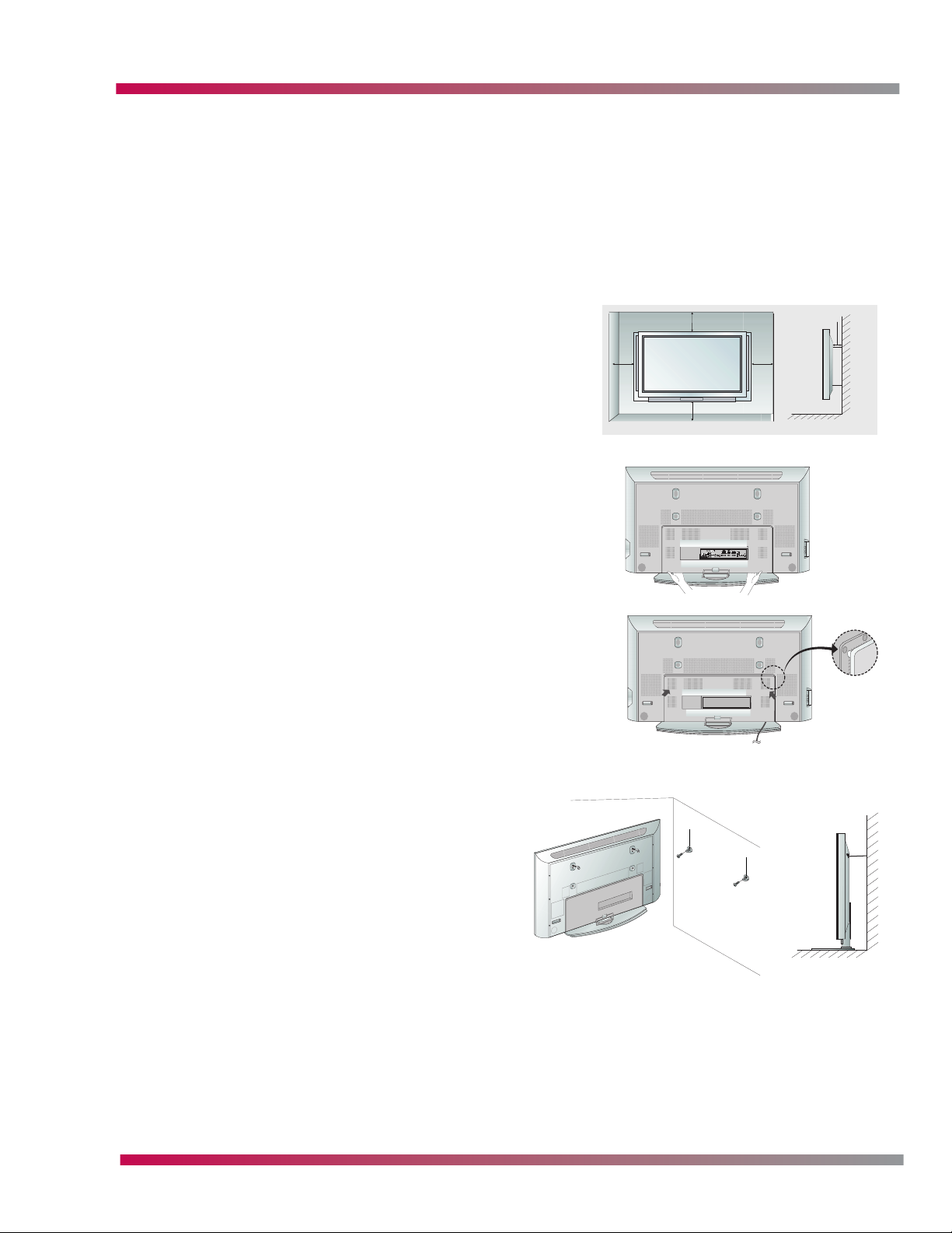
PLACEMENT
The TV can be installed in various ways such as on a wall, or
on a desktop etc. Some models can be mounted verically
(Portrait) or horizontally (Landscape). Do not mount models
that are not denoted as pivot models veritcally. For proper
ventilation, allow a clearance of 4 in. on each side and the
top, 2.36 in. on the bottom, and 4 in. from the wall.
JACKPACK COVER
Some models feature a jackpack cover. Remove the cover by
grasping the lower left and right of the cover and then pulling it
out.
Make the required connections and then replace the cover by
aligning the guide to the bushings and press the cover in place
with your hand.
4 inches
4 inches
2 inches
4 inches4 inches
ANTI-TIP BRACKETS
If the set will be mounted on a desk top, secure the
TV assembly by joining it to a wall by using the
included wall brackets. Some models are mounted
differently than others, refer to the owners manual
for the model you are installing.
Plasma Training 13 Installation
Page 14
INSTALLATION
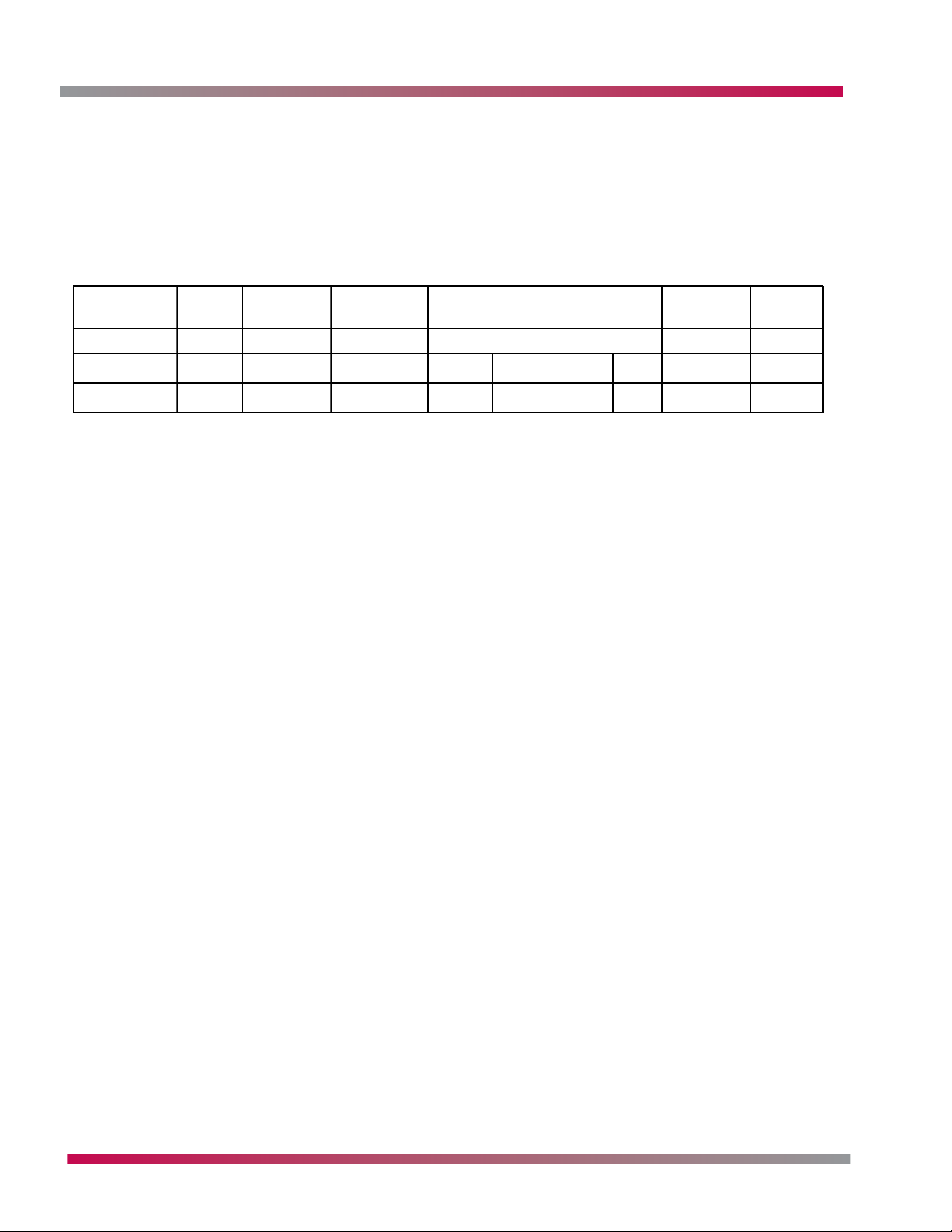
GENERAL MOUNTING
The chart below gives screw sizes needed to mount our plasma units to most wall mounts. The
design of the mount may require longer or shorter screws than the length indicated below. Lengh is
in the far right column. Use 25mm screws for the 42” and 50” plasma models and 15mm for the 60”
models. This is subject to change without notice. Some units require spacers between the mount and
the unit, this also varies by cabinet design.
Nominal
Nominal
Diameter
Diameter
Pitch
Pitch
Root
Root
Radius
Radius
Pitch
Pitch
Diameter
Diameter
Minor
Minor
Diameter
Diameter
Thread
Thread
Height
Height
Drill
Drill
Diameter
Diameter
Length
Length
mmmmh3 H1d3 D1d2=D2rPd = D
mmmmh3 H1d3 D1d2=D2rPd = D
254.20.40.4914.134.0194.480.1150.8M 5.00
254.20.40.4914.134.0194.480.1150.8M 5.00
154.20.40.4914.134.0194.480.1150.8M 5.00
154.20.40.4914.134.0194.480.1150.8M 5.00
Plasma Training 14 Installation
Page 15

OPERATION
OPERATION
This section covers basic TV functions and operation. Refer to the owners manual for additional
information.
NOTE: The DVR (Digital Video Recorder), DCR (Digital Cable Ready) and TV Guide features are
not discussed in this section, they each have their own section near the end of this
manual.
LANGUAGE
For best results, adjust or confirm adjustment of the On-Screen Menu Language first.
1. Press MENU on the Remote Control or Front Controls
2. Use the
3. Use the
4. Confirm the desired language selection.
U.S. models incorporate the three North American languages
(English, Spanish, French)
5. If the selected language is not desired, change the language by using the
to highlight the desired language setting and press the ENTER button to set the language.
6. Press EXIT to completely exit the On-Screen Menu or MENU to return to the previous
menu.
/
buttons to highlight the OPTION Menu (5
/
buttons to highlight the Language Menu (6
th
Menu) and press
th
Item) and press
/
buttons
TIP: If the language is set to Spanish, the Language Menu will be listed as “Lenguaje”. If the
language is set to French, the Language Menu will be listed as “Langue”. The main menu
list will not change.
SETUP MENU
The Setup Menu houses all of the services and options for TV channels and inputs.
EZ SCAN
The EZ Scan function will automatically scan for all available over-the-air (OTA) broadcast and/or
Cable TV Service channels and adds them to the “Channel Map”. Depending on individual model
features, EZ Scan can scan for OTA-NTSC (analog channels from antenna) labeled TV, OTA-ATSC
(digital channels from antenna) labeled DTV, CATV (analog Cable TV Service channels), and/or CADTV
(digital Cable TV Service channels).
1. Press MENU on the Remote Control or Front Controls
2. Use the
3. Use the
4. Press or ENTER to begin the EZ Scan process
5. Once the EZ Scan is complete, press EXIT to completely exit the On-Screen Menu or MENU
to return to the previous menu.
NOTE: If a Cable Box is used to decode CATV channels and output them to the TV via Ch3 or
Ch4, the CATV and CADTV channels will not be scanned by the EZ Scan function.
/
buttons to highlight the SETUP Menu (1st Menu) and press
/
buttons to highlight EZ Scan (1st Item)
NOTE: If a CableCARD™ is used, CATV and CADTV scans are not performed by the EZ Scan
function. CATV and CADTV channels are added to the “Channel Map” via the CableCARD™.
Plasma Training 15 Operation
Page 16

OPERATION
TIP: The EZ Scan function will re-add previously deleted channels to the “Channel Map”. In
order to maintain Channel Map preferences, the manual scan option should be used for
individual channel additions.
MANUAL SCAN
The Manual Scan option allows users to manually add channels to the “Channel Map” without
having to perform a complete scan.
1. Press MENU on the Remote Control or Front Controls
2. Use the
3. Use the
4. Use the or ENTER buttons to enter the Manual Scan function
5. Use the
6. Use the button to move to the channel number field
7. Use the
8. Press the ENTER button to save the channel.
9. Press EXIT to completely exit the On-Screen Menu or MENU to return to the previous
menu.
/
buttons to highlight the SETUP Menu (1st Menu) and press
/
buttons to highlight Manual Scan (2nd Item)
/
buttons to select the channel type (TV/DTV/CATV/CADTV)
/
buttons to select the channel number
NOTE: Input physical channel numbers instead of virtual channel numbers. (For Example, WXYZ
may broadcast NTSC on Ch 5 and ATSC on Ch 9. Even though the ATSC broadcast appears
as Ch 5-1, 5-2, etc., the physical channel number is Ch 9 while the virtual channel
assignment or “5” is carried in the PSIP data.)
CHANNEL EDIT
The Channel Edit feature allows users to specify channel usage. Users may add or delete channels
from the Channel Map. (The add function primarily operates on channels that have already been
added to the Channel map and previously deleted. Use the Manual Scan function to add a new
channel.) Users may also create a Favorite Channel Map by using the Channel Edit feature and
marking specified channels “FAV”.
1. Press MENU on the Remote Control or Front Controls
2. Use the
3. Use the
4. Use theor ENTER buttons to enter the Channel Edit function
5. Use the
6. To Add / Delete a channel, press the ENTER button
7. To mark or remove a channel from the Favorite Channel Map, press the FAV button
8. Press EXIT to completely exit the On-Screen Menu or MENU to return to the previous
menu.
/
buttons to highlight the SETUP Menu (1st Menu) and press
/
buttons to highlight Channel Edit (3rd Item)
/
/
/ buttons to select a channel number
TIP: To switch between channel types, TV, CATV, DTV, CADTV, move to the top of the window
and select the tab that corresponds with the desired channel type.
DTV SIGNAL STRENGTH
The DTV Signal Strength functions displays a bar meter showing the current strength of the incoming
ATSC signal. This feature only applies to digital channel reception and is not available for NTSC
channels. This feature is designed to aid in antenna placement and alignment for ATSC reception.
Plasma Training 16 Operation
Page 17

OPERATION
1. Press MENU on the Remote Control or Front Controls.
2. Use the
3. Use the
4. Use the or ENTER buttons to display the DTV Signal Meter.
5. Press EXIT to completely exit the On-Screen Menu or MENU to return to the previous
menu.
TIP: You may also display the DTV Signal Meter by pressing the SIGNAL button on the Remote
Control.
CHANNEL LABEL
The Channel Label feature allows users the ability to assign a network logo to individual channels.
1. Press MENU on the Remote Control or Front Controls.
2. Use the
3. Use the
4. Use the or ENTER buttons to enter the Channel Label Setup Screen.
5. Use the Channel Up / Down buttons to select the desired channel.
6. Use the
7. Press ENTER to assign the logo to the channel.
8. Press EXIT to completely exit the On-Screen Menu or MENU to return to the previous
menu.
/
buttons to highlight the SETUP Menu (1st Menu) and press
/
buttons to highlight DTV Signal (4th Item).
/
buttons to highlight the SETUP Menu (1st Menu) and press .
/
buttons to highlight Channel Label (5th Item).
/
/
/ buttons to select the desired logo.
NOTE: Not all Network Logos are available. Memory limitations restrict the amount of logos
that can be available within the software of the TV.
MAIN INPUT
The Main Input option selects the TV’s input (picture source) to be displayed on the screen.
1. Press MENU on the Remote Control or Front Controls
2. Use the
3. Use the
4. Use the or ENTER buttons to enter the Main Input Selection List
5. Use the
6. Press ENTER to confirm input selection
7. Press EXIT to completely exit the On-Screen Menu or MENU to return to the previous
menu.
SUB INPUT
The Sub Input option selects the input (picture source) to be displayed as Picture-In-Picture (PIP).
1. Press MENU on the Remote Control or Front Controls
2. Use the
3. Use the
4. Use the or ENTER buttons to enter the Main Input Selection List
5. Use the
6. Press ENTER to confirm input selection
/
buttons to highlight the SETUP Menu (1st Menu) and press
/
buttons to highlight Main Input (6th Item)
/
buttons to highlight the desired input (Antenna, Cable, Video 1, etc)
/
buttons to highlight the SETUP Menu (1st Menu) and press
/
buttons to highlight Sub Input (7th Item)
/
buttons to highlight the desired input (Antenna, Cable, Video 1, etc.)
Plasma Training 17 Operation
Page 18

OPERATION
7. Press EXIT to completely exit the On-Screen Menu or MENU to return to the previous
menu.
NOTE: Not all inputs are available for Sub Input at all times. When the Main Input being used
is a digital type, the available Sub Inputs are Analog Broadcast, Video, and Front Video.
When the Main Input being used is an analog type, the available Sub Inputs are DTV,
Analog, Video, and Front Video.
INPUT LABEL
The Input Label feature allows users to rename the TV’s inputs for easier identification.
1. Press MENU on the Remote Control or Front Controls
2. Use the
3. Use the
4. Use the or ENTER buttons to enter the Input Label Selection List
5. Use the
6. Use the
Box, Game, PC, or none)
7. Repeat Steps 5 and 6 to add more input labels
8. Press EXIT to completely exit the On-Screen Menu or MENU to return to the previous
menu.
/
buttons to highlight the SETUP Menu (1st Menu) and press
/
buttons to highlight Input Label (8th Item)
/
buttons to select an input source
/
buttons to select the input label (VCR, DVD, Set Top Box, Satellite, Cable
VIDEO MENU
The Video Menu houses all of the services and options for Picture adjustment.
EZ PICTURE
The EZ Picture option is a series of pre-set values for picture appearance for particular program
categories. Typical EZ Picture options include:
Daylight – A bright setting to help compensate for high levels of ambient light normally
experienced during daytime hours.
Night Time – A dim setting to help compensate for reduced levels of ambient light normally
experienced during nighttime hours.
Normal – An average setting to use as a default setting, or as a starting point for adjustments.
Movie – A setting to enhance the appearance of film based movies.
Video Game – A setting to enhance the appearance of video games.
Sports – A setting to enhance the appearance of sporting events.
TIP: There is an additional setting labeled Custom, which has no preset levels. The Custom setting
selects the most recent stored settings from Manual Picture Control.
1. Press MENU on the Remote Control or Front Controls
2. Use the
3. Use the
4. Use the
5. Press ENTER to save the selection
6. Press EXIT to completely exit the On-Screen Menu or MENU to return to the previous
menu.
/
buttons to highlight the VIDEO Menu (2nd Menu) and press
/
buttons to highlight EZ Picture (1st Item) and press
/
buttons to highlight the desired setting
Plasma Training 18 Operation
Page 19

OPERATION
MANUAL PICTURE CONTROL
The Manual Picture Control option allows users to set individual picture controls such as Contrast,
Brightness, Color, Tint, Sharpness, and Color Temperature. The Manual Picture Controls should be
used to properly set the display once it is in a users home. The environment around the display will
affect the perceived quality of the display. For example, the color of the walls and flooring will
affect the color levels seen on the display. Also, the amount of ambient light in the room will affect
the brightness of the display.
To properly set the Manual Picture Control levels:
1. Make sure the display is in its final place in the room. (If the display is moved to another
position, the controls will need to be re-adjusted.)
2. Adjust ambient light. The adjustments should be made for night time movie watching as,
this is when consumers are most critical of picture quality. The room should be darkened
with little to no ambient light in front of the display. For best results, and to reduce the
chance of eye strain, there should be slight ambient light behind the display.
3. Turn off or disable any additional video signal processing such as: XD Engine, Velocity
Scan, etc
4. Set EZ Picture to the Normal setting.
5. Set Color Temperature to the Warm setting.
Contrast – The Contrast control is used to adjust the White Level of the display. The proper setting
for contrast is only high enough to allow the difference between white and light gray to be seen.
When contrast is set too high, light grays will appear washed out or white, and whites can begin to
bloom or over saturate with color (appear slightly blue, pink, or green). When contrast is set too
low, whites will appear gray.
To properly set the Contrast Level, lower the contrast setting so that white becomes gray. Next,
begin stepping up the contrast level until the lightest gray color becomes white (white and gray
sections become one larger section) and then move the control down one step. There should always
be a noticeable difference between white and light gray and also note that for best results on all
display types (and to reduce display wear) the Contrast Level should be no higher than “85”.
Brightness – The Brightness control is used to adjust the Black Level of the display. The proper
setting for brightness is only high enough to allow the difference between black and dark gray to be
seen. When brightness is set too high, blacks will appear washed out or gray. When brightness is set
too low, dark grays will appear black.
To properly set the Brightness Level, begin stepping down the brightness level until the darkest
gray disappears into black (at the same time, black and “blacker-than-black” will mix into one.
Next, step the brightness level up once so that, black and “blacker-than-black” remain together yet
the darkest gray is visible.
NOTE: The Brightness and Contrast controls interact with each other. The current brightness
setting will affect the white level and the current contrast setting will affect the black
level. Therefore, you may need to readjust the contrast setting after adjusting the
brightness setting, and likewise readjust the brightness setting after subsequent contrast
settings. Keep repeating the adjustment until the black and white levels are reached.
Color – The Color control is used to adjust the Color Saturation of the display. The proper setting
for color is to the point where the primary (red, green, & blue) and sub-primary (yellow, cyan, &
magenta) colors appear as their pure, natural colors without “bleeding” into other colors. When
Plasma Training 19 Operation
Page 20

OPERATION
color is set too high, predominant colors, such as red, will bloom and bleed, causing white to
appear pink, and yellow to appear orange. When color is set too low, the entire image will appear
more gray than colored, with the extreme lower limit resulting in a Black & White picture. To
properly set the Color Level, lower the color setting to the point where colors begin to appear gray.
Next, begin stepping up the color level until the primary and sub-primary colors begin to exceed
their normal color representations.
Tint – The Tint control is used adjust the Hue of the display between red or green. The proper
setting for tint is, as with the color setting, to the point where the primary (red, green, & blue)
and sub-primary (yellow, cyan, & magenta) colors appear as their pure, natural colors without
bleeding into other colors. The extreme settings of tint will result in a red/magenta overall hue or
a green/cyan overall hue. To properly set the Tint control, adjust towards red if yellows appear with
a green tint or towards green is yellows appear with a red or orange tint.
NOTE: The Color and Tint controls interact with each other. The current color setting will affect
the hue and the current tint setting will affect the saturation. Therefore, you may need
to readjust the color setting after adjusting the tint setting, and likewise readjust the tint
setting after subsequent color settings. Keep repeating the adjustment until the best
color representation is reached.
TIP: After Color and Tint adjustments are completed, reds may over saturate slightly, causing
yellows to appear orange. You may need to slightly reduce the color level to compensate
for this effect.
Sharpness – The Sharpness control is used to adjust the amount of data added to the display
image. When the sharpness control is set too high, white or jagged edges will appear on black lines
or the edges of objects. When the sharpness control is set too low, the edges of objects or black
lines will appear fuzzy. To properly set the Sharpness control, adjust the setting up or down until
black lines have crisp, clean edges, while maintaining the overall brightness level across the image.
TIP: If a noticeable difference is not seen during the sharpness adjustment, simply place the
control at the 50 mark.
1. Press MENU on the Remote Control or Front Controls
2. Use the
3. Use the
4. Use the
5. Press ENTER to save the selection
6. Use the
7. Press EXIT to completely exit the On-Screen Menu or MENU to return to the previous
menu.
Color Temperature – The Color Temperature control is used to adjust the color of gray on the
display between red and blue tint. The Cool setting will provide a slightly blue tint to the picture.
The Warm setting will provide a slightly red tint to the picture. Once the previous adjustments have
been made, the color temperature may be changed for personal preference.
/
buttons to highlight the VIDEO Menu (2nd Menu) and press
/
buttons to highlight the desired control and press
/ buttons to adjust the control
/
buttons to change to another control or
Video Reset
The Video Reset option will revert all video menu options to their factory preset values. The EZ
Picture function will revert to the Daylight setting and the custom settings are the same as Normal.
Plasma Training 20 Operation
Page 21

OPERATION
AUDIO MENU
The Audio Menu provides access to all of the services and options for Sound adjustment.
AUDIO LANGUAGE
The Audio Language setting allows a default language to be specified for any digital broadcasts that
might have alternate audio languages.
1. Press MENU on the Remote Control or Front Controls
2. Use the
3. Use the
4. Use the
/
buttons to highlight the AUDIO Menu (3
/
buttons to highlight Audio Language (1st Item) and press
/
buttons to select a default audio language
5. Press ENTER to save the selection
6. Press EXIT to completely exit the On-Screen Menu or MENU to return to the previous
menu.
EZ SOUNDRITE
The EZ SoundRite option prevents the audio level of television commercials from exceeding the
audio level of preceding television programs.
1. Press MENU on the Remote Control or Front Controls
2. Use the
3. Use the
4. Use the
/
buttons to highlight the AUDIO Menu (3rd Menu) and press
/
buttons to highlight EZ SoundRite (2nd Item) and press
/
buttons to highlight either Off or On
5. Press ENTER to save the selection
6. Press EXIT to completely exit the On-Screen Menu or MENU to return to the previous
menu.
rd
Menu) and press
EZ SOUND
The EZ Sound function is a series of preset audio settings to maximize the sound quality of various
program types.
Normal – Factory presets for treble, bass, and front surround
Stadium – Preset values for sporting events
News – Preset values to dialog with little to no background effects
Music – Preset values for musical events
Theater – Preset values for movies
TIP: There is an additional setting labeled Custom, which has no preset levels. The Custom
setting selects the most recent stored settings from Manual Sound Control.
1. Press MENU on the Remote Control or Front Controls
2. Use the
3. Use the
4. Use the
/
buttons to highlight the AUDIO Menu (3rd Menu) and press
/
buttons to highlight EZ Sound (3rd Item) and press
/
buttons to highlight the desired setting
5. Press ENTER to save the selection
6. Press EXIT to completely exit the On-Screen Menu or MENU to return to the previous
menu.
Plasma Training 21 Operation
Page 22

OPERATION
MANUAL SOUND CONTROL
Balance – The balance control is used to adjust the level of the left and right TV speakers. In
normal conditions, the balance control should be set to the middle (even) position. If the main
viewing position is not centered with the TV, adjust to balance control so that the speaker farther
from the main viewing position is has a higher level.
Treble – The treble control adjusts the level of higher frequencies of the audio
spectrum.
Bass – The bass control adjusts the level of lower frequencies of the audio spectrum.
1. Press MENU on the Remote Control or Front Controls
2. Use the
3. Use the
4. Use the
5. Press ENTER to save the selection
6. Use the
7. Press EXIT to completely exit the On-Screen Menu or MENU to return to the previous
menu.
/
buttons to highlight the AUDIO Menu (3rd Menu) and press
/
buttons to highlight the desired control and press
/ buttons to adjust the control
/
buttons to change to another control or
FRONT SURROUND
The Front Surround option provides extra processing to mimic surround sound effects using only
the TV’s 2-channel speakers.
3D EchoSound System – SRS Labs process for improving an incoming mono audio signal to
produce a simulated stereo effect. The 3D EchoSound system will also create a three-dimensional
sound by creating a wider and deeper sound stage.
SRS TruSurround XT – SRS Labs process for mimicking multi-channel surround sound effect from
2-channels of audio output. The SRS TruSurround XT process can also provide more clarity and bass
enrichment to stereo signals.
1. Press MENU on the Remote Control or Front Controls
2. Use the
3. Use the
4. Use the
5. Press ENTER to save the selection
6. Press EXIT to completely exit the On-Screen Menu or MENU to return to the previous
menu.
TV SPEAKER
The TV Speaker selection option is used to either enable or disable the TV’s internal speakers. If the
TV is connected to a home theater system and there is no desire for audio from the TV’s speakers,
the TV’s speakers may be turned off.
/
buttons to highlight the AUDIO Menu (3rd Menu) and press
/
buttons to highlight Front Surround (7th Item) and press
/
buttons to select the desired setting
1. Press MENU on the Remote Control or Front Controls
2. Use the
3. Use the
4. Use the
5. Press ENTER to save the selection
Plasma Training 22 Operation
/
buttons to highlight the AUDIO Menu (3rd Menu) and press 4
/
buttons to highlight TV Speakers (8th Item) and press
/
buttons to select the desired setting
Page 23

OPERATION
6. Press EXIT to completely exit the On-Screen Menu or MENU to return to the previous
menu.
STEREO / SAP SETUP (NON-MENU OPTION)
This TV can receive both MTS stereo programs and any SAP (Secondary Audio Program) signal that
may be present. Pressing the SAP buttons on the Remote Control will cycle the TV between three
options; Mono, Stereo, and SAP. The Mono and Stereo options will provide audio from the MTS or
mono signal present from the broadcaster. The SAP option will provide audio in either another
language or another topic only if provided from the broadcaster.
NOTE: Even though the TV’s settings may be either Stereo or SAP, when a mono signal is the
only type provided by the broadcaster, mono sound will be heard (unless 3D EchoSound
System is selected).
TIP: If the incoming signal is very weak, selecting Mono will improve the sound output of a
stereo broadcast when the audio is fading in and out.
TIME MENU
The Time Menu provides access to all of the services and options for Clock and Timer adjustments.
AUTO CLOCK
The Auto Clock option allows the TV’s clock to be set automatically via either XDS signals from a
PBS broadcaster or from Gemstar’s TV Guide On Screen (TVGOS) signal. Non-TVGOS models – Auto
Clock will set the clock based on XDS signal from a PBS broadcaster. TVGOS models – Auto
Clock will set the clock based on the incoming TVGOS signal.
1. Press MENU on the Remote Control or Front Controls
2. Use the
3. Use the
4. Use the
5. If On is selected, use the
6. Use the
7. Press ENTER to save the selection
8. Press EXIT to completely exit the On-Screen Menu or MENU to return to the previous
menu.
MANUAL CLOCK
The Manual Clock option allows direct setting of the TV’s clock.
1. Press MENU on the Remote Control or Front Controls
2. Use the
3. Use the
4. Use the
5. Use the
6. Repeat Steps 4 and 5 to set the date and time
7. Press ENTER to save the selection
8. Press EXIT to completely exit the On-Screen Menu or MENU to return to the previous
menu.
/
buttons to highlight the TIME Menu (4th Menu) and press
/
buttons to highlight Auto Clock (1st Item) and press
/
buttons to select Off or On and press
/
buttons to select the time zone the TV is located in
/
buttons to select the Daylight Saving option (Auto, Off, On)
/
buttons to highlight the TIME Menu (4th Menu) and press
/
buttons to highlight Manual Clock (2nd Item) and press
/ buttons to select Year
/
buttons to set the current year
Plasma Training 23 Operation
Page 24

OPERATION
NOTE: The Manual Clock option is not available if TVGOS has been setup.
TIMER
The timer functions allow the TV to automatically turn on or off at specified times.
OFF TIMER
1. Press MENU on the Remote Control or Front Controls
2. Use the
3. Use the
4. Use the
5. If set to On, use the
6. If set to On, use the
7. Press ENTER to save the selection
8. Press EXIT to completely exit the On-Screen Menu or MENU to return to the previous
menu.
ON TIMER
1. Press MENU on the Remote Control or Front Controls
2. Use the
3. Use the
4. Use the
5. If set to On, use the
6. If set to On, use the
7. If set to On, use the
8. If set to On, use the V buttons to set the volume for the TV to turn on at
9. Press ENTER to save the selection
10. Press EXIT to completely exit the On-Screen Menu or MENU to return to the previous
menu.
/
buttons to highlight the TIME Menu (4th Menu) and press
/
buttons to highlight Off Timer (3rd Item) and press
/
buttons to select Off or On and press
/
buttons to set the hour
/
buttons to set the minute
/
buttons to highlight the TIME Menu (4th Menu) and press
/
buttons to highlight On Timer (4th Item) and press
/
buttons to select Off or On and press
/
buttons to set the hour
/
buttons to set the minute
/
buttons to set the channel for the TV to turn on to
NOTE: The TV must be in Stand-by mode for the On function to operate.
TIP: The time must be set before the timer functions can operate.
NOTE: If there is no interaction from a user (any Remote Control or Front Control button)
within 2 hours of the TV turning On under the On Timer function, the TV will turn back
off. This is a safety measure built into the TV to prevent the TV from accidentally turning
on.
SLEEP TIMER
The Sleep Timer function allows the TV to turn off after specified intervals of time.
1. Press MENU on the Remote Control or Front Controls
2. Use the
3. Use the
4. Use the
/
buttons to highlight the TIME Menu (4th Menu) and press
/
buttons to highlight Sleep Timer (5th Item) and press
/
buttons to select the desired time interval and press
5. Press ENTER to save the selection
6. Press EXIT to completely exit the On-Screen Menu or MENU to return to the previous
menu.
Plasma Training 24 Operation
Page 25

OPERATION
TIP: Pressing the SLEEP button on the Remote Control will also activate the Sleep Timer
function. Once activated, each subsequent press of the SLEEP button will change the
time interval (10, 20, 30, 60, 90, 120, 180, 240 minutes, or off).
AUTO OFF
The Auto Off function, when activated, will automatically turn the TV off if there is no input signal
for 10 minutes. This feature is useful when watching DVD Movies or using a Cable TV Box.
1. Press MENU on the Remote Control or Front Controls
2. Use the
3. Use the
4. Use the
5. Press ENTER to save the selection
6. Press EXIT to completely exit the On-Screen Menu or MENU to return to the previous
menu.
OPTION MENU
The Option Menu houses general options and settings for additions control of the TV.
ASPECT RATIO CONTROL (ARC)
The Aspect Ratio Control function adjusts the way that 4:3 programs are displayed.
/
buttons to highlight the TIME Menu (4th Menu) and press
/
buttons to highlight Auto Off (6th Item) and press
/
buttons to select Off or On
Set By Program – Disables ARC processing and allows the original aspect ratio of the incoming
program to be displayed.
4:3 – Displays 4:3 content without any correction, showing bars on both sides of the picture
16:9 – Displays 4:3 content stretched horizontally, consuming the entire screen
Horizon – Displays 4:3 content stretched only at the sides to consume the entire screen. The
center portion of the image is not stretched.
Zoom 1 – Enlarges the overall size of 4:3 content to consume the entire screen without and
distortion. However, the upper and lower portions of the image will be cropped.
Zoom 2 – Enlarges the overall size of 4:3 content to a greater extent than Zoom 1
Cinema Zoom – Adjustable enlargement of the Zoom function. (1-16)
1. Press MENU on the Remote Control or Front Controls
2. Use the
3. Use the
4. Use the
5. Press ENTER to save the selection
6. Press EXIT to completely exit the On-Screen Menu or MENU to return to the previous
menu.
CINEMA 3:2 MODE SETUP
The Cinema 3:2 Mode provides additional process for 480i content (particularly movies) to help
reduce the flickering caused during the conversion of 24 fps film to 30fps television signals.
/
buttons to highlight the OPTION Menu (5th Menu) and press
/
buttons to highlight Aspect Ratio (1st Item) and press
/
buttons to select the desired ARC setting
1. Press MENU on the Remote Control or Front Controls
2. Use the
3. Use the
Plasma Training 25 Operation
/
buttons to highlight the OPTION Menu (5th Menu) and press
/
buttons to highlight Cinema 3:2 Mode (2nd Item) and press
Page 26

OPERATION
4. Use the
5. Press ENTER to save the selection
6. Press EXIT to completely exit the On-Screen Menu or MENU to return to the previous
menu.
NOTE: Cinema 3:2 Mode only operates in 480i mode.
CAPTION
Closed Captions are included in the NTSC and ATSC television signals to provide text of dialog spoken
in the program.
To activate / deactivate Captions:
1. Press MENU on the Remote Control or Front Controls
2. Use the
3. Use the
4. Use the
5. Press ENTER to save the selection
6. Press EXIT to completely exit the On-Screen Menu or MENU to return to the previous
menu.
/
buttons to select Off or On
/
buttons to highlight the OPTION Menu (5th Menu) and press
/
buttons to highlight Caption (3rd Item) and press
/
buttons to select Off or On
CAPTION/TEXT
The Caption/Text option is used to select the type (NTSC) or language (ATSC) of captions to be
displayed.
Incoming NTSC broadcast signal:
CC 1 – Closed Captions that are in English and in time with spoken dialog
CC 2 – Closed Captions that are not required to be in time with spoken dialog
CC 3 – Closed Captions that are in an alternate language
CC 4 – Open use, without specifications
Text 1 – Near full screen Closed Captions in time with spoken dialog
Text 2 – Near full screen Closed Captions not required to be in time with dialog
Text 3 – Open use near full screen captions
Text 4 – Open use near full screen captions
NOTE: Most broadcasts will only include CC1 and are not required to use any other format.
Incoming ATSC broadcast signal:
English – English captions
Spanish – Optional Spanish captions
French – Option French captions
1. Press MENU on the Remote Control or Front Controls
2. Use the
3. Use the
4. Use the
5. Press ENTER to save the selection
6. Press EXIT to completely exit the On-Screen Menu or MENU to return to the previous
menu.
/
buttons to highlight the OPTION Menu (5th Menu) and press
/
buttons to highlight Caption/Text (4th Item) and press
/
buttons to select the desired option
Plasma Training 26 Operation
Page 27

OPERATION
CAPTION OPTION
The Caption Option setting is only available when the incoming signal is a DTV broadcast and if the
settings within the PSIP signal (provided by the broadcaster) allow alteration of the caption
display. When available, the caption text may be altered by size, font, and color.
Size – Set the size of the captions
Font – Set the font of the captions
Text Color – Set the color of the caption text
Text Opacity – Set the opaqueness of the caption text
Background Color – Set the background color of the captions
Background Opacity – Set the opaqueness of the caption’s background
Edge Type – Set a border for the captions
Edge Color – Set a color for the caption border
1. Press MENU on the Remote Control or Front Controls
2. Use the
3. Use the
4. Use the
5. Use the
6. Repeat Steps 4 and 5 to set the edit all of the desired items
7. Press ENTER to save the selection
8. Press EXIT to completely exit the On-Screen Menu or MENU to return to the previous
menu.
/
buttons to highlight the OPTION Menu (5th Menu) and press
/
buttons to highlight Caption Option (2nd Item) and press
/
buttons to select the desired item
/ buttons to set the item option
EZ DEMO
The EZ Demo option demonstrates the available menus of the TV.
1. Press MENU on the Remote Control or Front Controls
2. Use the
3. Use the
/
buttons to highlight the OPTION Menu (5th Menu) and press
/
buttons to highlight EZ Demo (7th Item) and press
4. Press EXIT to stop the demonstration
LOCK MENU
The Lock Menu allows change of of the Parental Controls / V-Chip settings for the TV to block
specific channels, ratings and/or inputs. The Parental Control function blocks programs based on
the ratings sent by the broadcaster. The default setting allows all programs to be viewed. To use
this functions, the following must be performed:
1. Set ratings and categories to be blocked
2. Set a Parental Control password
3. Enable the locking system
TO ENTER WHILE LOCKED:
1. Press MENU on the Remote Control or Front Controls
2. Use the
/
buttons to highlight the LOCK Menu (6th Menu) and press
3. Enter the password (0000 is the default password)
Plasma Training 27 Operation
Page 28

OPERATION
4. Use the
5. Use the
6. Press ENTER to save the selection
7. Press EXIT to completely exit the On-Screen Menu or MENU to return to the previous
menu.
TIP: If the password is forgotten, “7777” will reset it.
MOVIE RATING SYSTEM
G – General audience (all ratings below are blocked)
PG – Parental guidance suggested (all ratings below are blocked)
PG-13 – Parents strongly cautioned (all ratings below are blocked)
R – Restricted (all ratings below are blocked)
NC-17 – No one 17 and under admitted (all ratings below are blocked)
X – Adult only
Blocking Off – Permits all programs
TELEVISION RATING SYSTEM
/
buttons to highlight the desired system and press
/
buttons to set the desired blocking
TV-G – General audience
TV-PG – Parental guidance suggested
TV-14 – Parents strongly cautioned
TV-MA – Mature audience only
TV-Y – All children
TV-Y7 – Children 7 years and older
TV RATING CHILDREN (OPTION – SETTING)
Age – TV-Y and TV-Y7
Fantasy Violence – TV-Y7
TV RATING GENERAL (OPTION – SETTING)
Age – TV-G TV-PG TV-14 TV-MA
Dialog (sexual dialog) – TV-PG TV-14
Language (adult language) – TV-PG TV-14 TV-MA
Sex (sexual situations) – TV-PG TV-14 TV-MA
Violence – TV-PG TV-14 TV-MA
INPUT BLOCK (DISABLES EXTERNAL INPUTS)
Video1, Video 2, Front Video
Component 1, Component 2
RGB, HDMI1/DVI, HDMI2
Plasma Training 28 Operation
Page 29
PCB LAYOUT
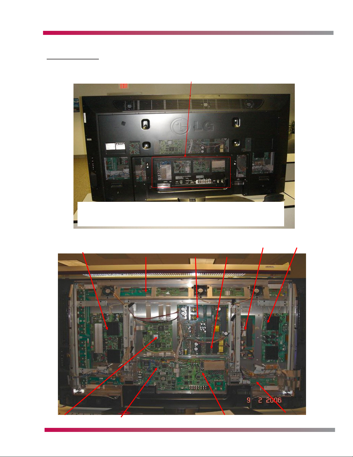
60PY2DR LAYOUT
CIRCUIT DESCRIPTIONS
Sub Cover
Accessing the Digital PCB or the Tuner PCB is made easier than on past
units by removing the sub back cover. The whole back can be removed
while the unit is on the original stand.
Y-Drive
X-Top Drives
Secondary
Power
Board
Primary
Power
Board
AC
Filter/Rectifier
Z-Drive
Tuner BoardDigital BoardControl Board
Plasma Training 29 Adjustments
X-Bottom Drives
Page 30
CIRCUIT DESCRIPTIONS
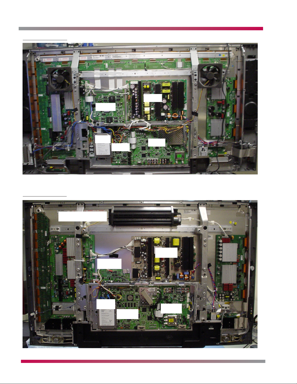
50PX4DR LAYOUT
Control
SMPS
50PC1DR LAYOUT
Squirrel cage fan
SMPS
HDD
Control
Digital
Tuner
SMPS
Tuner
Digital
HDD
Tuner
Digital
NOTE: This fan does not startup when the unit is powered on from a cold start for 2-3 minuets.
Plasma Training 30 Adjustments
Page 31

CIRCUIT DESCRIPTIONS
DIGITAL PCB
The digital board below is from the 60PY2DR, other models may differ slightly.
The digital PCB provides Digital Signal Processing (dsp) and controls the state of each FET on each
DRIVER B/D with R, G, B, each with 8bit input. This board contains the Cablecard slot and supporting
buffers which are shared with the Cablecard while it is in operation due to the data flow from the
cable headend to the card. This data flow constantly updates the channel list and the CP (Copy
Protect) data and the channel authorization list and the encription and descramble data. This is done
every ten to twenty seconds. This PCB also is host to the HDD (Hard Disk Drive) control circuit. This
circuit will recognize the HDD if it is programmed and formated correctly. These drives are setup
especially for this function, thus a drive from another vender will not function in this unit. This is
done for CP (Copy Protect) reasons. If the HDD is suspect of errors or video issues, power down the
unit and remove A/C and disconnect the IDE cable and power the unit back on. If the problem still
exists, the problem is not on the HDD. The unit can be used without the HDD connected. In this
situation the unit will function normally except any function related to the HDD or demo mode which
is stored on the HDD. This PCB also contains all of the Digital inputs. The analog to digital conversion
is done on this PCB as well.
Plasma Training 31 Adjustments
Page 32

CIRCUIT DESCRIPTIONS
4
4
TX/RX P2,N2
1394_OUT_TP[0:7]
PX4D PDP BLOCK
PX4D PDP BLOCK
POD_TP[0:7] LK,VALID,SOP
11
1.8V
Reg.
Reset
PVSB/OOB
X-tal (M)
IF±(6M)
nd
2
IIC A
0¡¿C2
ATSC/NTSC
U-
Com
CableANT.
(TPA±,TPB±)*2
1394
Controller
1394_IN_TP[0:7]
MUX
CPLD
11
VPP_SW
POD/OOB
Controller
LGDT3502
VSB_DATA
(LGDT3701)
IF_AGC
Tuner
(TDVS-H701P)
RF
TX/RX P1,N1
I/F
X-tal
(25M)
SATA
(TSB43DA42)
PC`I Bus
CableCARD circuit
(XC95144XL)
2
Flag
8
D
PI
14
8
PO
8
CRX
2
IIC D
0¡¿1C
OOB IF+/-
MSP
4440
SIF
OOB Tuner
(TAEU-H015P)
SW
IIC A
0¡¿C6
(SiI3512)
HD2_NT2CLK
TPN_SYS_CLK
EPLD_CLK
SDRAM
Voltage
LTC1470
Controller
POD
DRX
IIC D
0¡¿50
uCom
(M37151)
MSP
4440
SIF
NTSC Tuner
(TAFM-H103P)
IIC A
0¡¿C0
LGDPLL
CY2305SC
32MByte (8MB x4)
VPP1
DPLL_R[1:3]
(LGDT1901A)
FR_60
HD2_SYS_CLK
VCXO
27Mhz
64-Bit I/F
1.8V
Reg.
TP/D1
9
HD2_TP[0:7]
OR3
656 Data[0:7]
9
IIC C
0¡¿8A
Video Decoder
+3D Comb
X-tal
(24.576M)
V
IN5
V
OUT2
TV
IN1
IN1
YC
V, L R
2
3
Rear AV_1
Rear S_1
Video In/Out
Video In/Out
HD2_VDPClk (74.25M)
HD2_MAIN_PWM
CLK
(uPD64011A)
Sub
IN3
EPF_L/R
XDR_DATA_R/G/B[0:9]
IEP LGDT4410
IIC C
0¡¿1E
HD-II (Ver2.2)
-TP De-Mux
- MPEG Decoding : MP@HL
H,V,CLK
YCbCr24
3
OR1
OR4
H,V,CLK
YCbCr
3
16
IIC C
0¡¿B8
)
Video Decoder
+3D Comb
X-tal
(24.576M
OUT1
A/V SW
(CXA2069)
IN4
IN6
IN4
YC
V,LR
3
2
Side AV_4
Side S_4
MNT_V_Out
HD2_CVBS_OUT
HD-II
IIC C
12
LVDS Tx.
(THC63LVD103)
RGB
DOutClk
3
HV,Hact
30
-Format Converter
-Host I/F, Memory I/F
-Digital I/F
-Video DAC, NTSC Encoder
FID
OR2
Gemstar VBI Slicer & IR CKT
FID
(uPD64011A)
2MB
SDRAM
Main
IIC D
0¡¿90
OUT3
OUT1
2
Ext_ Audio LR
4440
M_MSP
0¡¿1C
SPDIF Out
MUX
(74LCX157)
SPDIF_BYPASS_SEL
HD2_ICE958_OUT
HD2_DAC_SCK/LRCK
AH_SPDIFCLK
-AC-3 Decoder/SPDIF In/out
OR1
OR4
YCbCr
H,V, CLK
24
ADC
(AD9883A)
(6/38MHz)
Active LPF
YCbCr
3
)
IIC D
0¡¿84
Video SW
(CXA2181
IN4
IN3
YCbCr
YCbCr
3
3
Comp_1
Comp_2
Control GPIO
SPDIF_IN_BYPASS
System
3
IN1
IN2
RGBHV
5
RGB-PC
Peripheral Bus
CPLD1
(XC95288XL)
)
(PIC18F1220
Slicer U-COM
H,V
SYNC
(MM1108XF)
SEPARATOR
CXA2069
IIC C
0¡¿98
FID
H,V,CLAMP
3
(XC95288XL)
System CPLD1
H,V
5
EPF_RGB-PC RGBHV
SPDIF In1(DVI)
SPDIF Receiver.
Slicer Data
(LM311M)
Voltage Comp.
ANALOG DE/
MULTIPLEXER
Sub_CVBS
OR2
HV_pol
HV_PC
AT/NT Tuner
SPDIF In2(DVD)
Sil9021
RX_HDMI_SPDIF
IIC B
0¡¿20
(CS8415A)
EEPROM
IIC B
0¡¿58
IR U-COM
(PIC18F242)
(74HCT4053)
PWM AMP
(TAS5122)
PWM_L/R
IIC D
0¡¿CC
PWM
MODULATOR
2
LPF
LPF
I2S
I2S_MCLK
NT Tuner
SIF
2
LR
LR
CXA2069
MNT_Out
RS-232C
(ST3232)
PCI Bus
(AT24LC512)
IIC C
0¡¿AE
GLink
GEM_IR_OUT
HD-II
I2S In
3
(NSP2100A)
AUDIO ADC
BUFFER
ANALOG_L/R
IIC D
0¡¿80
Sound Proc
LR
LR
2
2
Comp_2
Comp_1
SDRAM
64MB(32MBx2)
32Bit Bus I/F
Reset
CPU [PPC 405GPr]
EN[0:3(GPIO)]
G_LINK_CONN
IIC A
HD-II
I2S
Out
3
Buffer
(CS5331)
(74LCX244)
I2S Out
(MC33078)
3
(MSP4440)
LR
2
2
RGB(Phone)
KIA7029
74LCX244
- SDRAM Controller
- Peripheral Controller
- Local BUS I/F
IIC B
OR1
RGB
24
RXD[0:2]¡¾, RXCLK¡¾
8
HDMI 1
Flash Memory
16MB(8MBx2)
Peripheral Bus
- Serial(2), GPIO, I2Cr
I2C Hub
(PCA9516)
IIC D
IIC C
OR4
H,V,
CLK
3
SiL 9021
HDMI Rx
BSS83
BSS83
RXD[0:2]¡¾, RXCLK¡¾
DDC(I2C)
M
EEPRO
M
EEPRO
2
HDMI 2
CS8415A
RX_HDMI
SPDIF
IIC C
0¡¿60,68
BSS83
BSS83
DDC(I2C)
8
2
Plasma Training 32 Adjustments
Page 33

1394_OUT_TP[0:7]
POD_TP[0:7]
CLK,VALID,SOP
(PY2DR - PX4DR) PDP DVR BLOCK
(PY2DR - PX4DR) PDP DVR BLOCK
OOB/POD Controller
LGDT350
VSB DATA
/RESET
+3.3V
1.8V
Reg.
IF±(6M)
nd
2
IIC A
0¡¿C2
ATSC/NTSC
U-
Com
CableANT.
4
(TPA±,TPB±)*2
1394
Controller
1394_IN_TP[0:7]
TP_ENC[0:7]
MUX
CPLD
(XC95144XL)
11
VPP_SW
VPP_SW
2
POD/OOB
Controller
2
11
DRX / CRX
IIC D
X-tal
LGDT3701
IF_AGC
SIF
Tuner
(TDVS-H701F)
RF
SW
4
TX/RX P2,N2
TX/RX P1,N1
X-tal
(25M)
(SiI3512)
SATA I/F
(TSB43DA42)
HD2_NT2CLK
PCI Bus
KFIR-II
TP_V1[0:7]
PDR_PES[0:7]
TPN-II
TPN_TP[0:7]
2
Voltage
Flag
8
D
Add.
[0:13]
14
PI
8
8
PO
IIC D
0¡¿1C
uCom
(25M)
M_MSP
4440
M_MSP
SIF
OOB IF+/-
OOB Tuner
(TAEU-H015P)
6
0¡¿C
IIC A
IIC A
A)
LGDPLL
(LGDT1901
C
CY2305S
TPN_SYS_CLK
EPLD_CLK
SDRAM
32MByte (8MB x4)
SDRAM
(4Mx16Bit)
(LGDT1303)
KFIR-II
LTC1470
Controller
VPP1
POD
IIC C
0¡¿50
(M37151)
V
V
4440
NTSC Tuner
(TAUM-H501P)
0
Video In/Out
Video In/Out
0¡¿C
HD2_VDPClk
FR_60
HD2_SYS_CLK
VCXO
27Mhz
HD2_MAIN_PWM
64-Bit I/F
Reg.
1.8V
TP/D1
9
TP_ENC[0:7]
HD2_TP[0:7]
OR3
244
Buf.
9
656 Data[0:7]
CLK
SDRAM
(1Mx 16Bit)
)
X-tal
0¡¿BA
(24.576M
2
Filter
(FMS6410)
2
IN5
(Sub)
OUT2
TV
IN1
IN1
YC
V, L R
3
2
Rear AV_1
Rear S_1
CXA2069
XDR_DATA_R/G/B[0:9]
DPLL_R[1:3]
HD2_REC_CVBS
IEP
LGDP441
(74.25M)
IIC C
0¡¿1e
HD-II (Ver2.2)
-TP De-Mux
TPN-II /
MUX CPLD
TP_ENC[0:7]
KFIR-II
(BCM7040)
244
Buf.
PDR
CLK
Sub MSP4440
(UPD64011)
Video Decoder
Filter
(FMS6410)
2
OUT1
A/V SW
(CXA2069)
IN3
IN6
IN4
V,LR
3
EPF_L/R
Side AV_2
HD2_CVBS_OUT
HD-II
TX[0:4]¡¾
0
- MPEG Decoding : MP@HL
-Format Converter
PCI Bus
SDRAM
(2Mx 32Bit)
SDRAM
X-tal
IIC C
0¡¿B8
2
IIC A
(Main)
IN4
YC
2
Side S_2
MNT_V_Out
12
TXC¡¾
LVDS Tx.
RGB
3
HV,Hact
-Host I/F, Memory I/F
-Digital I/F
YCbCr
24
OR1
YCbCr
16
(1Mx 16Bit)
(24.576M)
IIC B
IIC C
IIC B
OUT3
Ext_ Audio LR
M_MSP
(THC63LVD103)
LGDP4411
DOutClk
30
HD2_ICE958_OUT
-Video DAC, NTSC Encoder
-AC-3 Decoder/SPDIF In/out
FID
H,V,CLK
3
OR2
OR4
FID
H,V,CLK
3
(UPD64011)
Video Decoder
IIC D
0¡¿90
OUT1
2
4440
SPDIF Out
MUX
(74LCX15
OR1
YCbCr
ADC
Active LPF
YCbCr
IIC B
0¡¿84
IN4
YCbCr
YCbCr
3
Comp_1
Comp_2
SPDIF_IN_BYPASS
7)
SPDIF_BYPASS_SEL
VBI Slicer & IR (USA Only)
OR4
H,V,
CLK
24
3
(AD9883A)
(FMS6407)
3
Video SW
(CXA2181
IN3
RGBHV
3
RGB-PC
CIRCUIT DESCRIPTIONS
RS-232C
(ST3232)
Sil9021
RX_HDMI_SPDIF
PCI Bus
0¡¿20
EEPROM
(AT24LC512)
IIC C
CPU
UART1_RX/TX
GEM_IR_OUT
PIC18F242
PWM AMP
(TAS5122)
PWM AMP
(TAS5122)
I2S In
PWM
(NSP6241B)
AUDIO ADC
MODULATOR
BUFFER
ANALOG_L/R
I2S
I2S_MCLK
0
0¡¿8
IIC D
SIF
2
LR
LR
2
2
Comp_1
Comp_2
MNT_Out
0¡¿A6
G_LINK_CONN
HD-II
3
(CS5331)
)
(MC33078
Main
(MSP4440)
Sound Proc
LR
2
RGB(Phone) LR
SDRAM
64MB(32MBx2)
32Bit Bus I/F
Reset
CPU [PPC 405GPr]
EN[0:3(GPIO)]
A
IIC
HD-II
I2S Out
3
Buffer
(74LCX244)
I2S Out
3
2
KIA7029
74LCX24
- SDRAM Controller
- Peripheral Controller
- Local BUS I/F
IICBIIC
OR1
RGB
H,V,
24
SiI 9021
HDMI Rx
BSS83
BSS83
EEPROM
8
2
DDC(I2C)
RXD[0:2]¡¾, RXCLK¡¾
- Serial(2), GPIO, I2Cr
I2C Hub
OR4
EEPROM
)
IN1
IN2
5
Control GPIO
Peripheral Bus
CPLD1
System
(XC95288XL)
AH_SPD
H,V
SYNC
SEPARATOR
CXA2069
IIC C
0¡¿98
H,V,CLAMP
3
System CPLD1
H,V
5
EPF_RGB-PC RGBHV
SPDIF In1(DVI)
HD2_DAC
SCK/LRCK
IFCLK
ANALOG DE/
MULTIPLEXER
(MM1108XF)
Voltage
MAIN_CVBS
OR2
FID
HV_pol
(XC95288XL)
HV_PC
KFIR-II
I2S
IIC D
0¡¿88
0
Sub
MSP444
Side L/R
Rear L/R
NT Tuner
SPDIF In2(DVD)
IIC B
(CS8415A)
SPDIF Receiver.
U-COM
(PIC18F1220)
(74HCT4053)
Comp.
(LM311M)
PWM_L/R
IIC D
0¡¿2C
2
LPF
LPF
NT Tuner
AT/NT Tuner
LR
CXA2069
EPF_L/R
Flash Memory
16MB(8MBx2)
Peripheral Bus
4
6)
(PCA951
D
C
IIC
CS8415A
RX_HDMI_SPDIF
CLK
3
IIC C
0¡¿60,68,74
BSS83
BSS83
EEPROM
EEPROM
8
DDC(I2C)
RXD[0:2]¡¾, RXCLK¡¾
/RESET
Plasma Training 33 Adjustments
Page 34

CIRCUIT DESCRIPTIONS
TUNER PCB
TUNERS
JACK PACK
CABLE INPUT
A tuner is a device to adjust the resonant frequency of an antenna or transmission line to work most
efficiently at one frequency or band of frequencies. Most tuners do all the low level demodulation
needed to convert a radio signal into an on-screen image using a hardware DSP chip or ASIC; some
also have hardware MPEG decoders. This PCB contains three tuners, one OOB (Out Of Band), one
digital tuner, and an analog tuner.
NOTE: The RCA cables connecting the tuner to the RF adapter do NOT come with PCB replacements.
They must be removed from the original PCB and connected properly to deliver the correct
signal to the correct tuner.
NOTE: The ribbon cables seen in the upper left connect this PCB to the Digital PCB and will tear or
crease easily. A tear or crease can easily lead to a misdiagnosis. If these cables become creased
or damaged in any way. Test them with an ohm meter to check each conductor for continuity.
ANT IN
Plasma Training 34 Adjustments
Page 35

CIRCUIT DESCRIPTIONS
Tuner PCB
HDD
CON
(CN1500)
CON
(CN1101)
EPF Module
CON
(CN1501)
1394Link
TSB43DA42
1394_IN_TP
(IC900)
MUX CPLD
XC95144XL
001
000
VSB_TP
TP_V0(PDR_PES
(IC1100)
1394_OUT_TP
010
TP_V1
TP_ENC
TPN_TP
00
VSB_TP
1394_OUT_TP
011
100
POD_TP0
TPNII
01
10
POD_TP0
000
TP_V0
VSB_TP
TP_ENC
CON
(CN1102)
001
010
1394_OUT_TP
(BCM7040)
MPGE ENCODER
100
POD_TP0
656 Data
Sub Video
(IC601)
Decoder
uPD64011
TP/D1
Wired-OR
(IC1601)
Buffer 74FCT244
IEP-ll
(IC1305)
LGDP4411
LVDS
(IC1302)
THC63LVD103
HD-ll
(IC401)
LGDT1102C
CON
(CN1102)
EXT
Module
TO PDP
Wired-OR
(IC603)
Main Video
Decoder PD64011
ADC
AD9883A
(IC801)
HDMI Rx
(IC800)
SiI9993
TPNII
SATA controller
siI3512 (IC1500)
(IC100)
PCI BUS
MUX CPLD
TPN_TP
(LGDT1303)
LG POD
VSB/
Controller
/0x1C
QAM
LPF
(IC608)
FMS6410
V/Y,C
V
V
OUT2
IN1
A/V SW
IN1
TV V5
(IC101)
CXA2069
IN4
IN4
LPF
FMS6410
OUT1
OUT3
(IC607)
OUT1
IN3
LPF
Video SW
IN4
(IC800)
FMS6407
(IC300)
CXA2181
IN2
CPU PPC405GPr
SDRAM
(IC302, IC303)
Digital PCB
OOB(DCR) Tuner
(TU500)
ATSC/NTSC Tuner
(TU301)
RF
SW
NTSC Tuner
(TU302)
V,LR
Rear AV_1
Y/C
Rear S_1
V,LR
Side AV_4
Y/C
Side S_4
V,LR
Mnt Out_
MSP4450
L/R
YCbCr
YCbCr
Comp_2
Comp_1
RGB-DTV/-PC
Plasma Training 35 Adjustments
Page 36

CIRCUIT DESCRIPTIONS
POWER SUPPLY
MAIN STANDBY SMPS 60PY2DR
P801
MAIN SMPS PCB 60PY2DR
P805
Plasma Training 36 Adjustments
Page 37
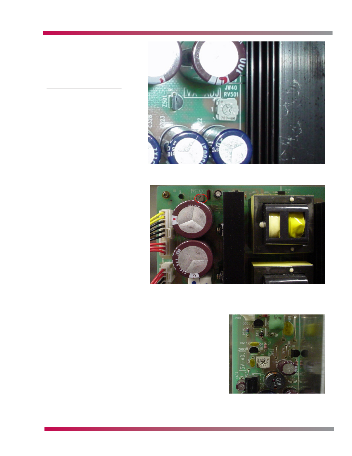
VA ADJUSTMENT 60PY2DR
The VA adjustment on the main
SMPS has no designated test point.
The DVM will have to be connected
to P805 pin 9 or 10 and the
negative lead to chassis ground.
Refer to the panel label for the
correct setting.
CIRCUIT DESCRIPTIONS
VS ADJUSTMENT 60PY2DR
VS adjustment also has no dedicated
test point. Use P805 pins 1, 2, or 3
and connect the negative probe
from a DVM to chassis ground. Refer
to the panel label for the correct
setting.
5V ADJUSTMENT 60PY2DR
This 5V adjustment can be tested on P801 pin 5 to chassis gnd.
Plasma Training 37 Adjustments
Page 38

CIRCUIT DESCRIPTIONS
P805
50PX4DR SMPS
P801
50PX4DR SMPS ADJUSTMENTS
VCC Adjusment to adjust StandBy voltages at P801
VA ADJUSTMENT 50PX4DR
VA adjustment use P805 pin 9 or 10 and chassis ground to
test
Plasma Training 38 Adjustments
Page 39

50PC1DR SMPS
CIRCUIT DESCRIPTIONS
P805
50PC1DR SMPS ADJUSTMENTS
Test points are from P805 pin 8, 9 or 10 for VS to
chassis ground. For VA, P805 pin 1 or 2 to chassis
ground. Refer to the panel label for the correct
settings.
This 3.3VDC is supplied for the cablecard and micro
processers in this unit. Test point is P803 pin 1 using
chassis ground for reference to ground.
VS adjustment
VA adjustment
Plasma Training 39 Adjustments
Page 40

CIRCUIT DESCRIPTIONS
50PC1DR POWER BLOCK DIAGRAM
x_WY
SI4925DY
SI4925DY
pjXWWXpjXWWZ
pjX]W\ pjX]W] pjX]W^
MC33078
MC33078
KIA78R09
KIA78R09
FAN4
FAN4
KIA78R09
KIA78R09
FAN2, 3
FAN2, 3
KIA78R09
KIA78R09
FAN1
FAN1
pj^W\
EPF Module
EPF Module
Ethernet BD
Ethernet BD
pj]WX
AZ1117-1.8
AZ1117-1.8
FMS6407
FMS6407
24LC02*2
24LC02*2
CS5331A
CS5331A
DS1621
DS1621
M62320
M62320
pj_WW
LGDP4411
LGDP4411
pj[WZ
AZ1117-3.3
AZ1117-3.3
+5.0V
{|XZWW
63LVDM83R
63LVDM83R
THC63L103
THC63L103
pj_W\
AZ1117-3.3
AZ1117-3.3
pjXXWY pjXXWW
pjXXWZ
pjXXWX
AT/NT Tuner w/OOB
MM1108
LM311
4053
LGDT1102F
LGDT1102F
POD Mod.
POD Mod.
AT/NT Tuner w/OOB
MM1108
LM311
PIC18F1220
PIC18F1220
4053
pj[WX
AZ1086-1.8
AZ1086-1.8
(1A)
AZ1117-1.8
82B715
82B715
EPM570_256
LCX14
LCX244
LGDT3703
LGDT3703
pj^W^
pj`W`
AZ1117-3.3
AZ1117-3.3
uPD64015*2
uPD64015*2
HY57161610*2
HY57161610*2
HY5DU573222
kkyTyht
HY5DU573222
AZ1117-1.5
AZ1117-1.5
pj`W]
pj^W_
AZ1117-1.8
AZ1117-1.8
LGDT1304
LGDT1304
24LC512
24LC512
Sil3512
Sil3512
pjYWW
242LP
242LP
CY2305*2
CY2305*2
EPM570_144
EPM570_144
LCX244*2
LCX244*2
HY57V561620*2
HY57V561620*2
LGDT3502
LGDT3502
29DL640*2
29DL640*2
29DL323*2
PPC405GPr
29DL323*2
PPC405GPr
pjXYWX
SC1565-2.5
SC1565-2.5
AZ1117-1.8
LGDT3703
LGDT3703
PCA9516
PCA9516
LGDT1901B
LGDT1901B
HY57V641260*4
HY57V641260*4
pjXWW^
pj`W[
pjYWZ
AZ1117-1.8
AZ1117-1.8
MST3361
AZ1117-2.5
CY2309
CY2309
TSB43DA42
TSB43DA42
MST3361
AZ1117-2.5
pj_WY
AZ1117-3.3
AZ1117-3.3
EPM570_256
pjYWX
LCX14
pj]WW
LCX244
+12.0V
+12.0V
KIA78R09
KIA78R09
HDD
HDD
pjX]W^
AT/NT Tuner
AT/NT Tuner
R\UW}
pjX_WY {|XZWX
PQ05DZ1U
PQ05DZ1U
PQ05DZ1U
+6.0V
pjZWX
pjX_W]
PQ05DZ1U
PQ05DZ1U
PQ05DZ1U
+6.0V
R\}s
Si3865
Si3865
pjZW[
ST3232
+5V_ST
+5V_ST
AZ1117-3.3
AZ1117-3.3
sp}lvu
ST3232
pjXWX
ZUZ}s
+3.3V_ST
+3.3V_ST
SC1565-1.8
SC1565-1.8
pjX[WX
ZUZ}
Si3865
Si3865
pjXZWX
AZ1117-1.5
AZ1117-1.5
w~yz~Y
AZ1117-1.8
wGiGkG
pj`W^
SC2595
AZ1117-1.8
SC2595
sGw
kGw
OvGkGiVkP
pj`W[
AZ1117-2.5
AZ1117-2.5
Plasma Training 40 Adjustments
Page 41

CIRCUIT DESCRIPTIONS
sGw
kGw
OkP
wGiGkG
VFD
VFD
ସXhହ
YWWh
RF_SW
RF_SW
ସX]Zhହ
MSP4450
MSP4450
ସY_hହ
ସY[hହ
ସ\hହ
ସRZUZ}ହ
TAS5122
TAS5122
R`UW}
pjZWX
CXA2069
ସ^YGhହ
CXA2069
ସX[\hହ
MSP4458G
MSP4458G
ସY\hହ
KA7809R
KA7809R
R\UW}
pjZWX
CXA2181
CXA2181
ସ__Ghହ
PQ05DZ1U
PQ05DZ1U
R\}z{ymz~
Si3865
Si3865
w~yz~X
NSP2100A
NSP2100A
pj\WY
ସZGhହସY[Ghହ
AT24C16
AT24C16
SC1565-1.8
SC1565-1.8
MTV416
MTV416
BA033-3.3
BA033-3.3
pj\W[
Si3865
Si3865
w~yz~Y
+20V
+20V
+12V
+12V
+6V
+6V
+5V_ST
+5V_ST
+3.3V_ST
+3.3V_ST
Plasma Training 41 Adjustments
Page 42

CIRCUIT DESCRIPTIONS
50PC1DR DATA BLOCK DIAGRAM
pYjjoXGOsP
pYjjoYGOkP
XW_Ww
kTp
Omsp_]]_P
W^]VW^_
W^W
pG
wGlU
pYjjoZGOsP
pYjjo[GOkP
Ot]YZYWP
W__
zGtzw
Otzw[[[WrP
W_W
tGtzw
Otzw[[[WrP
u{G{
OrGP
O{k}zTo`WXwP
Wj]
u{G{
O}wTX\yP
{
h{Vu{Vvvi
O{k}tTo^\XwP
WXj
wkwGt
z
Wih
u{Gk
Owk][WXYP
t
WjY
WjW
Wi_
u{Gk
Owk][WXYP
W`j
Otz{ZZ]XP
hkjGVGoktp
plwY
WXl
Osnkw[[XXP
|Tj
Ot{}[XYtmP
z
}ziVxht
t
}ziVxht
kwss
Osnk{X`WXiP
llwyvt
OY[sj\XYP
Osnk{Z^WZiP
Osnk{Z^WZiP
W\W
WiY
WXj
WXY
Wh]
khzw
OuzwYXWWhP
h}Gz
OjhYW]`xP
h}Gz
OjhYX_XxP
z
{U
OkzX]YXP
wGlU
Ot]YZYWP
zwkpm
y
Ojz_[X\hP
W]j
W`W
W_[
W`[
W^[
WYW
pYjGo
Owjh`\X]P
jw|pYj
jw|
pYjGt
Owwj[W\nwP
pYjo|i
luXa[
jwsk
Olwt\^WP
Plasma Training 42 Adjustments
Page 43

PANEL DRIVE BOARDS
Y-SUSTAIN
CIRCUIT DESCRIPTIONS
Y-DRIVE
Function: Connected to Scan (Y) electrode and FPC to operate Scan and Sustain. Supply a wave form
that energizes the horizontal electrode sequentially. Generates a potential difference between GND
and Vpp only in scan period. Brightness and addresses of the pixels comes from this board.
Driver
ICs
Driver
Array
Power
Supply
Driver
boards
Plasma Training 43 Adjustments
Page 44

CIRCUIT DESCRIPTIONS
Below are test points for the Y-Drive PCB. It is best to use chassis ground for this scope reading. Use
the ground below when measuring DC voltage.
Vsetup adjustment
Vsetup adjustment
VR1 adjusts the timing
VR1 adjusts the timing
For the firing of the cells.
For the firing of the cells.
VR1 adjusts the timing
VR1 adjusts the timing
between Y and Z Sustain B41
between Y and Z Sustain B41
60PY2DR MAIN Y-DRIVE
During normal operation the Vsc at this testpoint is +75Vdc and -Vy is -84Vdc. These adjustments are
crucial to the panel performance. The effects you will get when _Vy is too high is minimal on a still
image. When this is set too low you will see after image and speckeling in the image due to lack of
elminating the previous displayed image. This occurs at around -125Vdc.
When Vsc is too low the brilliance of the image is not as strong due to lack of drive voltage, this is
hard to see with the naked eye. When Vsc is too high the panel begins to over drive and will reduce
the life of the panel.
Vsc Adjustment -Vy Adjustment
Vsc Testpoint -Vy Testpoint
Plasma Training 44 Adjustments
Page 45

MAIN Y-DRIVE
CIRCUIT DESCRIPTIONS
RAMP_DN WAVEFORM
SUS_DN WAVEFORM
RAMP_UP WAVEFORM
SUS_UP WAVEFORM
SW
ER_DN WAVEFORM
ER-UP WAVEFORM
Plasma Training 45 Adjustments
Page 46

CIRCUIT DESCRIPTIONS
Z-SUSTAIN
Function: Connected to Sustain (Z) electrode and FPC to operate Sustain. Make the SUSTAIN PULSE
and ERASE PULSE that generates SUSTAIN discharge in the panel by receiving the LOGIC signal from
the CONTROL B/D. Composed with IPM, FET, DIODE, electrolytic capacitor, E/R coil.
SUS_UP
ER_UP
SUS_DN
Z_BIAS
ER_DN
Plasma Training 46 Adjustments
Page 47

CIRCUIT DESCRIPTIONS
Earlier version of the Z-SUS PCB. Variable resistance of Z RAMP waveform.
ZER_UP
Waveforms for P1
taken from model
50DC1D on the next
page.
Plasma Training 47 Adjustments
WC
ZER_DN
Vs_CON
ZSUS_UP
ZSUS_DN
Z_BIAS
ZO_DUM1
Z-Bias Adjustment
103.0 VDC to chassis ground
Page 48

CIRCUIT DESCRIPTIONS
Waveforms for P1 taken from model 50DC1D. From the screen print (P1) as pin one and the black wire
as Pin 12.
PIN1
PIN4
PIN7
PIN2
PIN5
PIN8
PIN3
PIN6
PIN9
PIN10
Plasma Training 48 Adjustments
PIN11
PIN12
Page 49

CIRCUIT DESCRIPTIONS
X BOARD
The X board receives a LOGIC signal from the CONTROL B/D and controls the ADDRESS PULSE (generates
Address discharge) by an ON/OFF operation, and supplies the waveform to COF(data).
Signal part
Power part
Lift up lock. Pull
COF as shown by
arrow.
This Ribbon containes the COF IC’s.
Plasma Training 49 Adjustments
Page 50

CIRCUIT DESCRIPTIONS
SIGNAL CONTROL
Signal processing (Contour noise, reduction) controls the state of each FET on each DRIVER B/D with
R, G, B each with 8bit input (Uses 3.3V/5V 2 kinds of power ). This PCB controls all aspects of the
PDP panel. This PCB also digitally segments the panel and controls the pixels and cells as if the panel
was a large memory IC and changes the data as needed after screen by screen comparison. The data
that differs from one frame to another are the addresses that are reset and changed. The software in
this PCB differs greatly from the software in the Digital PCB.
Array저항
16 line
MCM
Buffer
IC
16 line
16 output
Plasma Training 50 Adjustments
Page 51

PLASMA PANEL
PANEL IDENTIFICATION AND LABELS
CIRCUIT DESCRIPTIONS
①
6####
②
402K242V6000266.ASLGA
③
2004.02
⑦
④⑤⑥
VOLTAGE LABEL
This voltage label is located on the back of the panel,
This data is crucial to setting the supplies from the
SMPS when a new PCB is installed.
① Model Name
② Bar Code
(Code 128, Contains the manufacture No.)
③ Manufacture No.
④ The trade name of LG Electronics
⑤ Manufactured date (Year & Month)
⑥ The place Origin
⑦ Model Suffix
Vsc-VyVsetup
PCB LABELS
Board Ass`y Part No.
BOARD NAME
PCB Part No
Plasma Training 51 Adjustments
Board Serial No.
Page 52

CIRCUIT DESCRIPTIONS
C
C
C
C
C
C
C
C
C
C
C
C
C
C
C
C
C
C
C
C
C
C
C
C
C
C
C
C
C
C
C
C
C
C
C
C
C
C
C
C
C
C
C
C
C
C
C
C
C
C
C
C
C
C
C
C
C
C
C
C
C
C
C
C
C
C
C
C
C
C
C
C
C
C
C
C
C
C
C
C
C
C
C
C
C
C
C
C
C
C
C
C
C
C
C
C
C
C
C
C
C
C
C
C
C
C
C
C
C
C
Anal
PCB
CIRCUIT DESCRIPTIONS
50PC1DR
Connector Pin Run Connector Pin Run Connector Pin Run Connector Pin Run
P805
Connector Pin Run 1 0 7 GND 11 2.5V D
P804
Connector Pin Stby Run 6 59.6VD
P800
P802
P803
SMPS Y- Drive
1 195.6V 1 195.6VD
2 195.6V 2 195.6VD
3 195.6V 3 195.6VD
40 40 4GND 40
5 GND 5 GND 1 4.95VD
6 GND 6 GND 2 4.95VD
7 GND 7 GND 3 4.95VD
8 GND 8 GND 4 4.95VD
9 59.6V 9 59.6VD
10 59.6V 10 59.6VD
1GND 2 0 8GND 12 0
2GND 34.9VD
3 5.00VD
4 5.00VD
1 4.78VD
2 4.42VD
3 4.97VD
4 0 0 3 5.0V D
504.6VD
604.9VD
704.9VD
8 4.98VDC4.9VD
90 0 8 0 1 0
10 0 0 9 4.7V D
11 5.98V D
12 0 0 11 .1VD
13 3.2VDC3.2VD
1 19.3VD
2 19.3VDC19.3VD
30 0 3 0 1 0
40 0 4 0 2 0
55.9VD
6 0 1 6 0 4 4.9VD
73.3VDC3.3VD
8 0 1 8 1.9V D
9 12.1VDC12.1VD
10 0 1 10 .3VD
13.3VDC3.3VD
23.3VD
30 0 132.6VD
40 0 142.8VD
55.9VD
65.9VD
70 0 170 62.0VD
80 0 181.0VD
9 12.1VDC12.1VD
10 12.1V D
11 0 0 21 1.3VD
12 0 0 22 3.7VD
4.8VD
4.42VD
4.9VD
5.9VD
19.3VD
5.9VD
3.3VD
5.9VD
5.9VD
12.1VD
P1
P2
P3
P4
44.9VD
50 3GND
7 59.6V D
10 6GND
25.17VD
40 960.3VD
56.0VD
61.5VD
73.9VD
10 0 3 4.9V D
12 0 5 0
10 660.3VD
24.42VD
52.6VD
70 50
90 760.3VD
11 .14V DCConnector Pin Run Connector Pin Run
12 0 1 GND 1 19.3V D
15 0 4 1.4VD
16 0 5 GND 5 5.9V D
19 0 8 2.16VD
20 .3VD
23 0 12 2.1VD
24 2.9V D
25 .33V D
26 .2VD
27 .28V D
28 0 17 GND 7 0
29 3.9V D
30 0 19 GND 9 GND
P5
P6
P1 01
15.0VD
25.0VD
3GND 31.3VD
5GND 9.5VD
6GND 10 0
og
2 2.69VD
3GND 3 0
7GND 73.3VD
9GND 912.1VD
10 1.9VD
11 GND 1 GND
13 GND 3 GND
14 2.2VD
15 GND 5 0
16 2.2VD
18 2.2VD
P1
P1 51
P1 52
P1 53
P3 01
P6 02
Z Board
11.0VD
22.4VD
5.7VD
60
70
80
14.9VD
24.9VD
4GND
5GND
71.9VD
860.3VD
10 1.4V D
11 196.5V D
12 196.5V D
20
44.9VD
760.3VD
34.9VD
660.3VD
219.3VD
40
60
80
10 0
23.3VD
44.9VD
64.0VD
83.3VD
10 3.3V D
Plasma Training 52 Adjustments
Page 53

CIRCUIT DESCRIPTIONS
P2P3P4
+/- 93 vdc
R111
Z Bias
P152P153
1
P151
1
A/C
Input
SC101
SMPS
P802P803P800
11
1
Z Drive
P1
1
P301P601P602P403P404
1
1
1
Speaker
P103
P101P102
Front Pannel
1
Speaker
RF Block
ATSC
NTSC
Side AV jacks
P110P310
RGB
OOB
P805 P804
FAN
P800
1
1
P2
P300P200
1
P1P5P6P4
1
1
OOB
ATSC
P107
P3
P1606
Control
P105 P106
1
P801
P1603 P1604
Tuner
NTSC
P1601
P1000
P101 P102
Digital Analog
P103
HDD
-VY
CableCARD
P300 P200 P100P210
+VSC
Ramp_up
11
P3
Y SUS
Vset_dn
P2
Vset_up
1
66v
66v
66v
Plasma Training 53 Adjustments
Page 54

TROUBLESHOOTING
TROUBLESHOOTING
This section addresses problems you may encounter. This section should be used in conjunction with
the Circuit Descriptions. There may be adjustments required after changing a board or component,
Refer to the Circuit Descriptions section.
Again, the DVR (Digital Video Recorder), DCR (Digital Cable Ready) and TV Guide features are not
discussed in this section, they each have their own section near the end of this manual.
SIGNAL CONTROL TROUBLESHOOTING
1. Confirm LED D17 is flashing, D13 is lit.
2. If not, CHECK OSC X1 output.
3. Check CTRL input voltage at P300
4. CHECK for 3.3V, 5V, 15V.
5. Check IC 11 for 3.3V, IC 3 for 2.5V
Probe point
OSC(X1)
Input
voltage
DMM –
(GND)
Diode
DMM +
Check IC
11,13
Plasma Training 54 Troubleshooting
Page 55

TROUBLESHOOTING
Z-SUSTAIN TROUBLESHOOTING
Check the output of X1 (normal is 100 MHZ). The DC/DC converter makes 5V,Va,Vs,Vset_up,Vsc which
is essential for each B/D. There is no separated DC/DC B/D in model our later plasma models. They
are embedded DC/DC circuits as part of another PCB as seen below.
Y_DRIVE PCB
NOTE:
Use a DVM as shown below set to diode check either forward or reverse bias to check the drive IC.
DMM + DMM -
Plasma Training 55 Troubleshooting
Check here with DMM (either forward or reverse)
Page 56

TROUBLESHOOTING
TROUBLESHOOTHING THE COF ICS
COF is Chip On Film. If any of the tests indicate the junction is shorted or leaking, the adjacent COF
IC is defective. As a result the PDP panel will have to be replaced. Each resistor is a 10.2 - 10.8 ohm
resistor.
DVM set to Resistance test
across the surface mount resistor.
DIAGRAM OF THE COF IC
DVM set to Diode test
BLK POC STB A6 A5 A4 A3 A2 A1
VSSP
OUT1
OUT96
Q1 Q2 Q3 Q4 Q5 Q6 Q94 Q95 Q96
LATCH
P bit shift register P
6
16
96
P bit shift register P
P bit shift register P
4
5
16
16
94
95
P bit shift register P
P bit shift register P
3
2
16
16
92
93
CLK
P bit shift register P
1
16
91
F/R
BSVPP
STV7620
Plasma Training 56 Troubleshooting
Page 57

50PC1D
230Vpp
Vsetup
TROUBLESHOOTING
30µs
+/-175V
Vs
V_Set up
100µs
200Vpp
Set down
85µs
Why the electric discharge happens when it is not supposed to.
Wavelength above shows V_setup /V_set down that created wall charges inside panel. The wall charges that
are created by
“setup/down” wavelength, has an important role for address electric discharge.
• If Vs is less than the value on the panel label.
• The slope of “set down” period descends
• The amount of wall charge decreases.
• The picture gets darker and set turns off eventually
• If VS is greater than the value of panel label.
• The slope of set down will shorten.
• Amount of wall charge increases
• Picture gets brighter because it can’t display gray scale.
Therefore, incorrect electric discharge occurs.
Z SUS_OUT
SUSTAINSCAN
230V
Vsetup
+/-175V
Vs
0V
Plasma Training 57 Troubleshooting
Y
setup
30µs
setdown
85µs
RAMP ERASE
Page 58
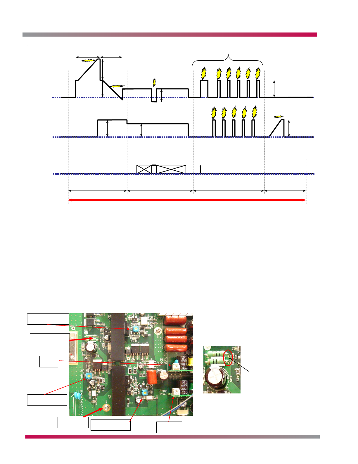
TROUBLESHOOTING
Scan (Y)
0 V
(GND)
Common
sustain (Z)
0 V
(GND)
Data (X)
0 V
(GND)
Set downSet up
Video image generation
230 V
180 V
( Vs )
180 V
110 V
170 V
180 V
65 V
12
34
56
78
Setup Scan ( Address ) Sustain Erase
1 sub-field
180 V
9
1. Increase the amount of wall charge by gradually increasing voltage.
2. Decrease created wall charge to certain amount by gradually decreasing voltage.
3. Prepare for scan to keep certain amount of wall charges.
4. Another line is scanning nothing happens.
5. Current line is scanning voltage obtained is X electrode and wall charge on Y electrode conflicts and
discharge occurs.
6. Wall charge increased by scan step.
7. Voltage obtained on Y electrode and wall charge in Z electrode conflicts and discharge occurs.
8. Voltage obtained on Y electrode and wall charge in Z electrode conflicts and discharge occurs.
9. Remove all wall charges by gradually increasing voltage.
Y-Sustain PCB testpoints:
RAMP_UP
Scope TP
DC TPoint
-VY
This test point is the
reference for all the following
signals referred to here.
Readings are taken with the
probe set to 10x1.
VSET_UP
Ground
Plasma Training 58 Troubleshooting
VSET_DN
+VSC
Page 59
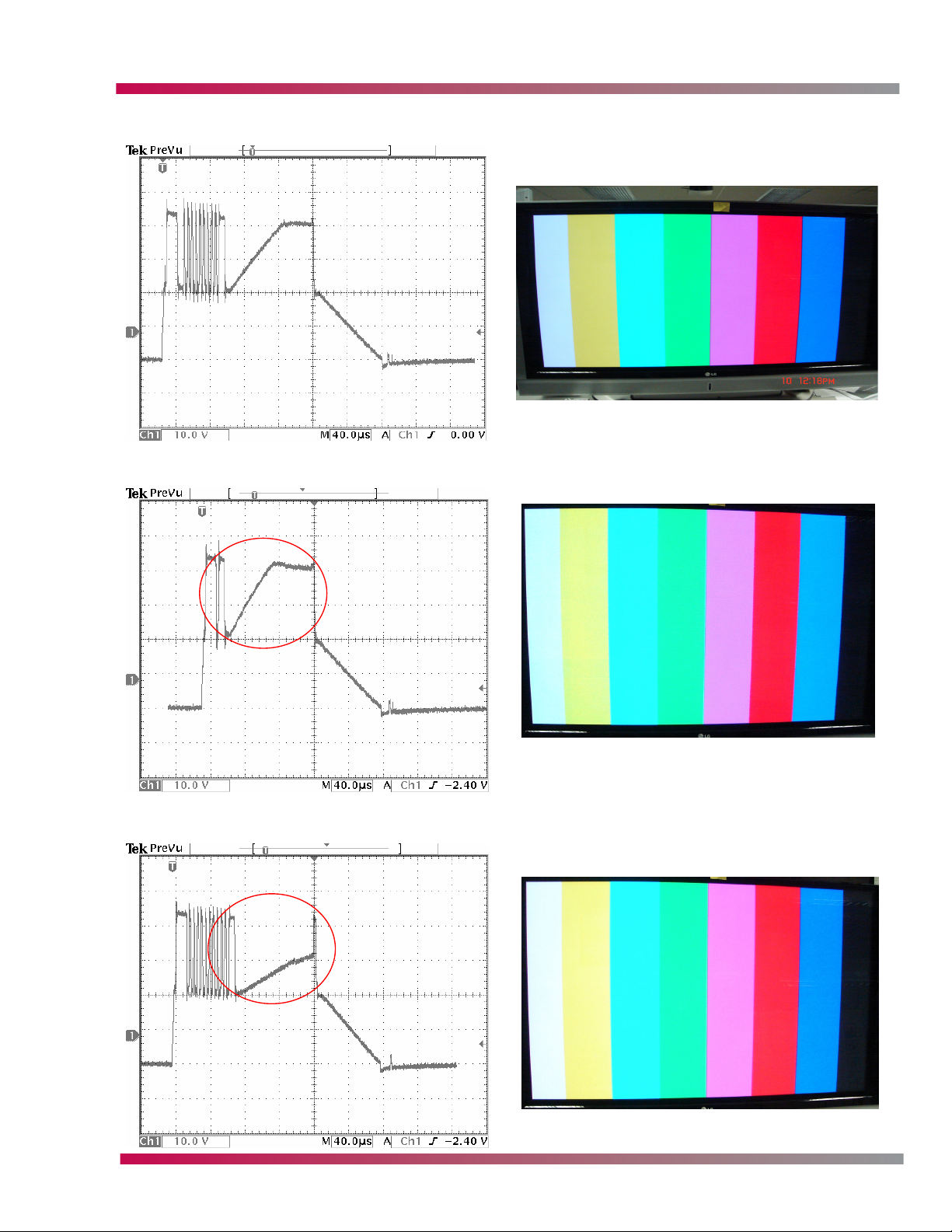
Normal waveform (20.6vdc)
Ramp_up too high (22vdc)
TROUBLESHOOTING
Noticeable low level color distortion with the
Ramp_up too low.
Ramp_up too low (15.2vdc)
Noticeable low level color distortion with the
Ramp_up too high.
Plasma Training 59 Troubleshooting
Page 60

TROUBLESHOOTING
Vset_DN too low (16.8vdc)
Vset_DN too high (19.7vdc)
All of the center washes out due to
decreased Vset_DN time.
The center begins to wash out and arc
due to decreased Vset_DN time.
Vset_UP too high (28.33vdc)
Very little alteration to the picture, the wave
form indicates a distorted Vset_UP. The
peek widens due to the Vset_UP peeking
too quickly.
Plasma Training 60 Troubleshooting
Page 61

Vset_UP too low (27.3vdc)
-VY too low (-154vdc)
TROUBLESHOOTING
The center begins to wash out and ark due
to Vset_UP Peeking too late and alters the
start of the Vset_DN phase.
Colors and the image will bloom slightly and
the unit will have difficulty with clean frame
changes in a quickly altering image.
-VY too high
The center begins to wash out and ark due
to –VY running to long and clipping.
Plasma Training 61 Troubleshooting
Page 62
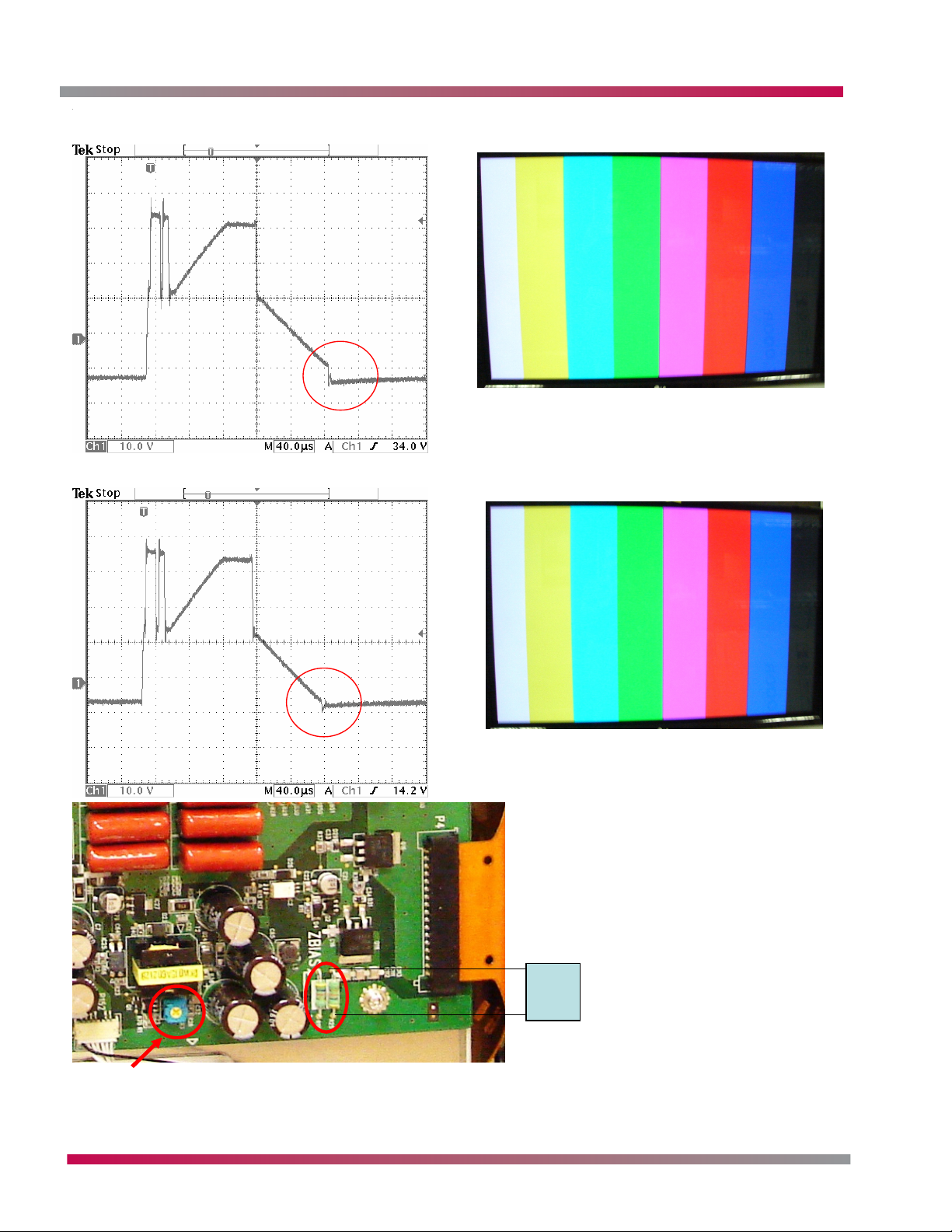
TROUBLESHOOTING
VSC too low
VSC too high
The image will show very little change but
there will Be some distortion in a quickly
changing image.
The image will show very little change but
there will be some distortion in a quickly
changing image.
DVM
DVM
ZBIAS adjustment: On the Z-Sustain PCB
ZBIAS adjustment: On the Z-Sustain PCB
With the DVM across R92 adjust the potentiometer till the DVM
With the DVM across R92 adjust the potentiometer till the DVM
reads 93 vdc.
reads 93 vdc.
Plasma Training 62 Troubleshooting
Page 63

TROUBLESHOOTING
VS VA adjustments. Refer to the panel label for the correct setting
Plasma Training 63 Troubleshooting
Page 64

TROUBLESHOOTING
MEMORY CARD ERRORS
Unable to create folder. Reached maximum number of folders.
Unable to create folder. No disk space.
First stop copying and retry M/C eject.
Copy protected. Unable to copy.
Not enough memory card space.
No memory card.
Unable to copy file.
Unable to move file.
Unable to delete file.
Unable to access. File or directory damaged.
Can't read data. Please remove memory card 1.
Can't read data. Please remove memory card 2.
Memory card 1 removed unsafely.
Memory card 2 removed unsafely.
NoteMessage
Maximum number of folder is 30.
HDD is full. Must delete a program/photo/music before record.
Cannot eject while copy operation is in progress
Cannot copy to memory card because it is copy protected.
Cannot copy to memory card because free space is too small.
Memory card not detected
Cannot copy
Cannot move
Cannot delete
Cannot readUnable to read file.
Damaged file or memory card
memory card 1 is not detected correctly
memory card 2 is not detected correctly
Must press eject button and select memory card before removing
Must press eject button and select memory card before removing
Plasma Training 64 Troubleshooting
Page 65

DISASSEMBLY
DISASSEMBLY
PREPARATION
Prepare a clean surface with protective padding and place the unit face down on the surface. The area
necessary to perform the panel replacement should equal approximately 4 times the panel size. Use
extreme caution handling the unit to avoid damaging the front glass filter panel.
Tools required to complete the replacement:
1) Electric or cordless screwdriver with a #2 Phillips head screwdriver bit.
2) Digital Multimeter
3) Non magnetic potentiometer adjustment tool/blade
4) Diagonal cutters
5) Nylon cable ties
Note: Remember to observe ESD Safety precautions when handling electronic printed circuit boards
and replacing the plasma display panel. Replace all cut cable ties with new ones to secure loose
wires.
Note: The stand must be removed from the plasma TV/monitor before servicing.
DISASSEMBLY OF THE DU-42PX12X
REAR COVER REMOVAL
1) If you can not remember the connection locations, label each connector with a marker or use
another method to identify the correct reconnect location.
2) Remove the rear cover screws. The arrows imprinted in metal rear cover
indicate the screws that need to be removed to remove the rear cover.
3) Place the rear cover to the side. Place it in an area where it is protected
from damage while unattached from the unit.
Plasma Training 65 Disassembly
Page 66

DISASSEMBLY
BOARD REMOVAL
4) Remove the four (4) mounting screws used to secure the module housing containing the Digital
and Analog boards.
5) Disconnect the AC input to the power supply board, connector P801
and Main power switch board connector P802.
6) Remove mounting screws shown in the picture, to remove the AC
power cord socket.
7) Disconnect the Side-Audio Video cable from connector P100
of the Analog control board connection.
Plasma Training 66 Disassembly
Page 67

DISASSEMBLY
8) Disconnect the cables P203 and P204 they are the speaker connectors.
9) Disconnect the Fan power connectors P704 and P705.
10) Remove the black fiberglass tape securing cable connection P201, and disconnect the cable.
11) Disconnect P801, P802, and P803 from the power supply board.
12) Disconnect the cable from connector P300 on the digital board. Leave the cable attached to
connector P807 of the power supply board.
13) Remove the complete signal board assembly
as a single piece.
14) Set the assembly aside. Place it in an area
where it is protected from damage while
unattached from the unit.
15) Disconnect the cables from the Y-Sustain
board, P151, that connect to the power
supply connectors P805 and P804. Retain
the cables to reuse. New cables are not
provided.
16) Disconnect the cables from the Z-Sustain board, P151,
that connect to the power supply connector P806.
Retain the cables to reuse. New cables are not
provided.
17) Remove two (2) mounting screws shown to remove
the Main Power switch from the cabinet. Remove
the power switch from the cabinet
assembly.
18) Remove the eight (8) mounting screws
from the Power Supply board and remove
the board from the panel.
19) Place the power Supply module aside after
removal, observing all ESD (Electro-Static
Discharge) precautions.
20) Disconnect the data cable from connector
P201 located on the digital board
mounted on the panel. Retain the cable
to reuse. New cables are not provided.
21) Remove the left cooling fan mounted on the defective panel mounting bracket by, removing the
(2) screws on each side of the fan.
Plasma Training 67 Disassembly
Page 68

DISASSEMBLY
PANEL REMOVAL
At this point, replace the panel if it has been determined to be defective and replacement is
necessary.
1) Remove the four (4) screws that retain the panel to the front cabinet assembly.
2) Remove the support rails screws indicated. Removing these screws will release the panel from
the cabinet.
3) Using the support rails, lift the defective panel up and out of the cabinet.
4) Place the panel on a flat padded surface away from the cabinet.
5) Remove the two (2) bolts fastening each support rail to the back of the defective panel. The
right side support rail has a cooling fan attached to it. It can remain attached through the
removal from the defective panel and re-installation to the placement panel.
INSPECT REPLACEMENT PANEL
Upon receiving the replacement panel, it must be inspected to ensure that it has arrived in good
condition. The following items should be observed to ensure that no shipping damage has occurred.
1) Check the outer carton for damage, and report it upon receipt
of the replacement panel.
2) Confirm the part number on the carton label is the part
number that was ordered or expected.
3) If the carton has arrived undamaged, open the carton after
receipt, and check the contents for damage or broken parts.
4) Confirm the replacement panel in the carton matches the
part number on the outer carton.
5) If everything is correct and un-damaged, the panel
replacement process can continue at this point.
Plasma Training 68 Disassembly
Page 69

DISASSEMBLY
INSTALL REPLACEMENT PANEL
Preparing the new panel for installation is the
same process as removal of the defective panel,
but it is performed in reverse.
1) Remove the new panel from the carton it
was received in, and place the panel on
an elevated surface. The protective material
connected to the panel must be removed.
The panel must be elevated approximately
2 inches to remove the protective ends.
2) Remove the four (4) bolts indicated and lift the end caps off of the panel.
3) Remove the tape holding the plastic wrap around the panel and pull the wrap back exposing the
panel and it’s circuit boards.
4) Re-install the support brackets on the replacement panel.
5) Secure the panel to the cabinet with the four (4) screws removed in earlier steps. Install the
eight (8) screws that secure the support brackets to the front cabinet assembly. Use extreme
caution installing the screws, to prevent stripping the screw holes and causing further delays.
6) Re-install the cooling fan on the left side of the panel.
7) Re-install the Power Supply board on the replacement panel. Install the eight (8) mounting
screws to secure the board to the panel backing.
8) Re-connect the cables from the power supply connectors P804 and P805 to the Y-Sustain board
connector P151.
9) Re-connect the cables from the power supply connector P806 to the Z-Sustain board connector
P151.
10) Locate the Digital board cable that was removed from the connector P501 on the Digital VSC
board, and connect it to P501 on the Digital board that is already mounted on the replacement
panel. Position the cable so that is accessible, and can be attached to P201 of the Digital VSC
board later.
Plasma Training 69 Disassembly
Page 70

DISASSEMBLY
INSTALL THE DIGITAL VSC BOARD
1) Locate the assembly shown, and place it back
on the support rails of the unit. Place the
assembly in the correct location so that the
screw holes line up correctly.
2) Install the four (4) screws in the frame securing
it to the support rails.
3) Reconnect the cable from the Side Audio/Video
jack inputs to connector P100 on the Analog/
Tuner board.
4) Reconnect the front control board cable to
the Digital VSC board connector P103.
5) Reconnect the Left side fan cable connector
to the connector P704 located on the Digital
VSC board. Connect the Right side cooling fan
connector to connector P705 on the Digital
VSC board.
6) Reconnect the speaker cables to the Analog/
Tuner board connector P203 and P204. Connect
the left speaker to connector P203, and the
right speaker cable to connector P204.
7) Reconnect the cable from the digital board
connector P501, to the Digital VSC board
connector P201.
8) Reconnect the cable from Digital VSC board
connector P706 to the Power Supply connector
P801.
9) Reconnect the cable from Digital VSC board
connector P701 to the Power Supply connector
P802.
10) Reconnect the cable
from Analog/Tuner
board connector
P201 to the Power
Supply connector
P803.
11)Reinstall retaining
screws that secure the
AC Power connector
to the right support
rail.
Plasma Training 70 Disassembly
Page 71

DISASSEMBLY
12) Reinstall the Main Power switch into the cabinet assembly using the two (2) screws that were
removed from the bracket during disassembly.
13) Reconnect the Power Switch cable connected to P801 to the power supply connector P810.
Connect the AC input cable socket wire leads to connector P802 of the power switch.
14) Use the nylon cable ties to secure all loose wiring. Inspect wiring for any pinched or damage
insulation and repair or replace if necessary.
This process completes the installation of the panel. The unit is ready to have AC power applied to the
set. The power supply Vs and Va run voltages must be checked and adjusted to the panel specifications.
The correct voltage settings are notated on an adhesive label placed on the backside of the panel.
VS AND VA VOLTAGE ADJUSTMENT
1) Apply power to the unit and turn it on. If the unit does not operate correctly, check all connections
and look for loose wires that may have been missed or that have become disconnected during the
reassembly process.
2) Allow the unit to run for 5 minutes. This is to allow the set to achieve operating temperature
before checking the Vs and Va run voltages. This step should be completed before making adjustments
to Vs and Va voltages.
3) Connect the positive ( + ) terminal lead of the digital multimeter to the Va pin of connector P805
and connect the negative ( - ) terminal lead of the digital multimeter to the ground ( GND ) pin of
P805.
4) Adjust variable resistor VR351 to match the Va
voltage specification shown on the label attached
to the panel. ( Deviation: ±0.5v )
5) Connect the positive ( + ) terminal lead of the digital
multimeter to the Vs pin of connector P805 and connect
the negative ( - ) terminal lead of the digital multimeter to the ground ( GND ) pin of P805.
6) Adjust variable resistor VR551 to match the Va
voltage specification shown on the label attached to
the panel. ( Deviation: ±0.5v )
7) After confirming the Vs and Va run voltages, the
set is ready to reassemble.
Plasma Training 71 Disassembly
Page 72

DISASSEMBLY
DISASSEMBLY OF THE 2DR MODELS
These instructions refer to the 50PY2DR and 60PY2DR
TOOLS REQUIRED
1) Electric or cordless screwdriver with a #2 Phillips head screwdriver bit.
2) Digital Multi-meter
3) Non magnetic potentiometer adjustment tool / blade
4) Diagonal cutters
5) Nylon cable ties
Note: Remember to observe ESD Safety precautions when handling electronic printed circuit boards
and replacing the plasma display panel. Replace all cut cable ties with new ones to secure loose
wires.
Note: The stand must be removed from the plasma tv / monitor before servicing.
REAR COVER
1) If you can not remember the connection locations, label each connector with a marker or use
another method to identify the correct reconnect location.
2) Remove the rear cover screws. The arrows imprinted in metal rear cover indicate the screws that
need to be removed to remove the rear cover.
3) Place the rear cover to the side. Place it in an area where it is protected from damage while
unattached to the unit.
Plasma Training 72 Disassembly
Page 73

DISASSEMBLY
4) Remove the four (4) mounting screws, used to secure the module housing containing the
Digital and Analog boards.
5) Disconnect the AC input to the power supply board,
connector PN1B.
6) Disconnect the Side-Audio Video cable from connector P100,
of the Analog control board connection.
Plasma Training 73 Disassembly
Page 74
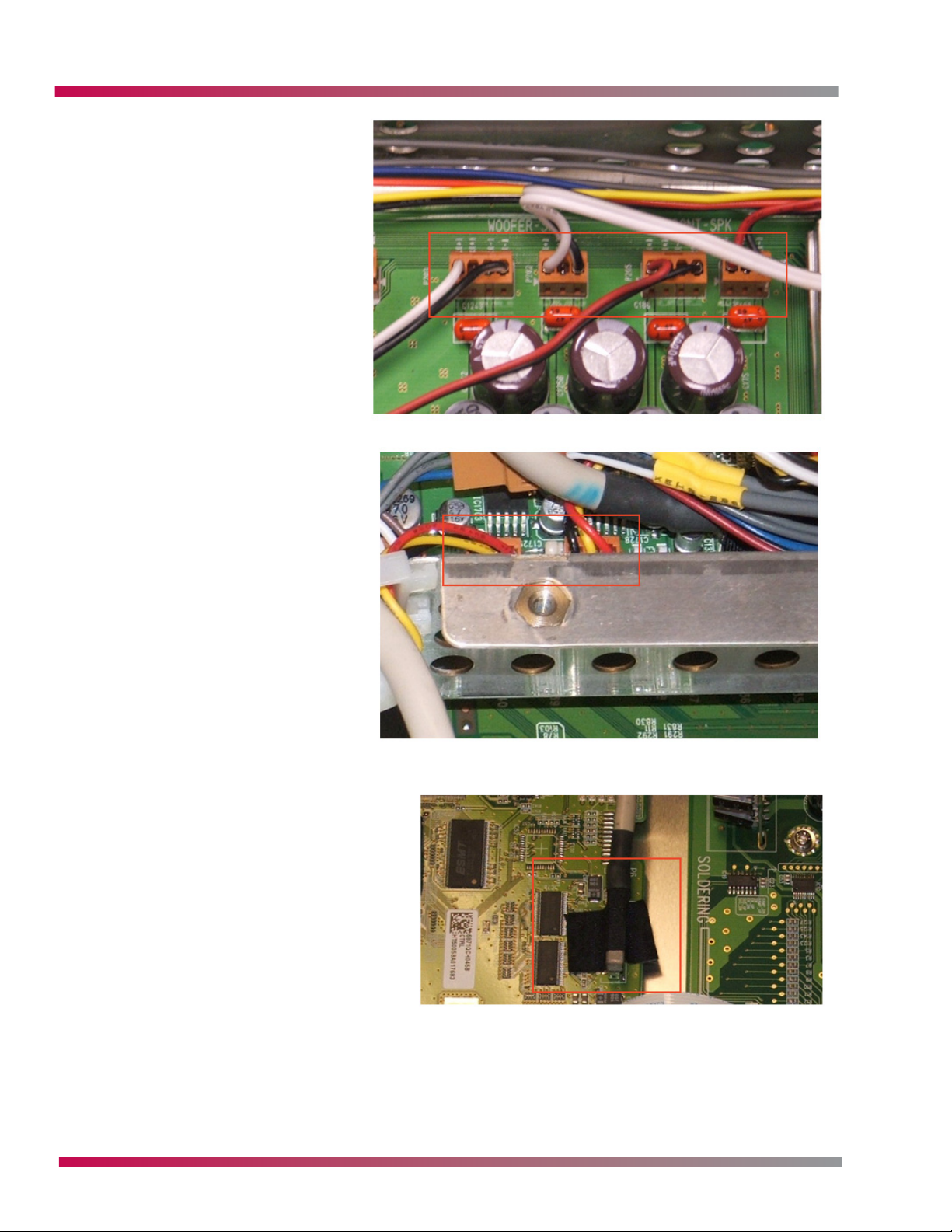
DISASSEMBLY
7) Disconnect the cables P202,
P203, P204 and P205, they are
the speaker connectors.
8) Disconnect the Fan power
connectors, CN1701, CN1702,
and CN1703.
9) Remove the black fiberglass tape
securing cable connectionCN1300, and
disconnect the cable.
Plasma Training 74 Disassembly
Page 75

DISASSEMBLY
10) Disconnect P802, P803, P804 and P805
from the power supply board.
11) Remove the complete signal board assembly, as a single piece.
12) Set the assembly aside. Place it in an area where it is protected from damage while unattached
to the unit.
13) Disconnect the cables from the Y-Sustain board P3 and P4, that connect to the power supply
connector P805 and P804. Retain the cables to reuse. New cables are not provided.
14) Remove the eight (8) mounting screws from the Power Supply
board and remove the board from the panel. Remove secondary
power supply at the same time.
15) Place the power Supply module
aside after removal, observing all
ESD (Electro-Static Discharge)
precautions.
Plasma Training 75 Disassembly
Page 76

DISASSEMBLY
PANEL REMOVAL
1) Remove the eight (8) screws that retain the panel and support rails to the
front cabinet assembly.
2) Remove the support rail screws indicated. Removing these screws will release
the panel from the cabinet.
3) Using the support rails, lift the defective panel up and out of the cabinet.
4) Place the defective panel on a flat padded surface away from the cabinet.
5) Remove the four (4) bolts fastening each support rail to the back of the
defective panel.
INSPECT REPLACEMENT PANEL
At this point if the panel has been determined to be defective and
replacement is necessary. Upon receiving the replacement panel, it
it must be inspected to ensure that it has arrive in good condition.
The following items should be observed to ensure that no shopping
damage has occurred.
1) Check the outer carton for damage, and report it upon
receipt of the replacement panel.
2) Confirm the part number on the carton label is the part number that was ordered or expected.
3) If the carton has arrived undamaged, open the carton after receipt, and check the contents for
damage or broken parts.
4) Confirm the replacement panel in the carton matches the part number on the outer carton.
5) If everything is correct and un-damaged, the panel replacement process can continue at this
point.
Plasma Training 76 Disassembly
Page 77

DISASSEMBLY
INSTALL REPLACEMENT PANEL
Prepare a clean surface with protective padding and place the unit face down on the surface. The area
necessary to perform the panel replacement should equal approximately 4 times the panel size. Use
extreme caution handling the unit to avoid damaging the front glass filter panel.
1) Remove the new panel from the carton it was received in, and place the panel on an elevated
surface. The protective material connected to the panel must be removed. The panel must be
elevated approximately 2 inches to remove the protective ends.
2) Remove the four (4) bolts indicated and lift the end caps off of the panel.
3) Remove the tape holding the plastic wrap around the panel and pull the wrap back exposing the
panel and it’s circuit boards.
4) Re-install the support brackets on the replacement
panel.
5) Secure the panel to the cabinet with the eight
(8) screws removed in earlier steps Install the
eight (8) screws that secure the support brackets
to the front cabinet assembly. Use extreme caution
installing the screws, to prevent stripping the
screw holes and causing further delays.
6) Re-install the Power Supply boards on the replacement panel. Install the sixteen (16) mounting
screws to secure the board to the panel backing.
7) Re-connect the cables from the power supply connectors P804 and P805 to the Y-Sustain board
connector P3.
8) Locate the Digital board cable that was removed from the connector CN1300 on the Digital VSC
board, and connect it to P30 on the Digital board that is already mounted on the replacement
panel. Position the cable so that is accessible, and can be attached to CN1300 of the Digital VSC
board later.
RE-INSTALL DIGITAL VSC BOARD AND ANALOG TUNER BOARD
1) Locate the assembly shown, and place it back on the support rails of the unit. Place the
assembly in the correct location so that the screw holes line up correctly.
2) Install the eight (8) screws in the frame securing it to
the support rails as shown.
3) Reconnect the cable from the Side Audio / Video jack
inputs to connector P101, and P106 on the Analog /
Tuner board.
4) Reconnect the front control board cable to the Analog
board connector P403.
5) Reconnect the fan cables connections to the connectors
CN1701, Cn1702 and CN1703 located on the Digital VSC
board.
6) Reconnect the speaker cables to the Analog / Tuner
board connector P202, P203 P204 and P205.
Plasma Training 77 Disassembly
Page 78
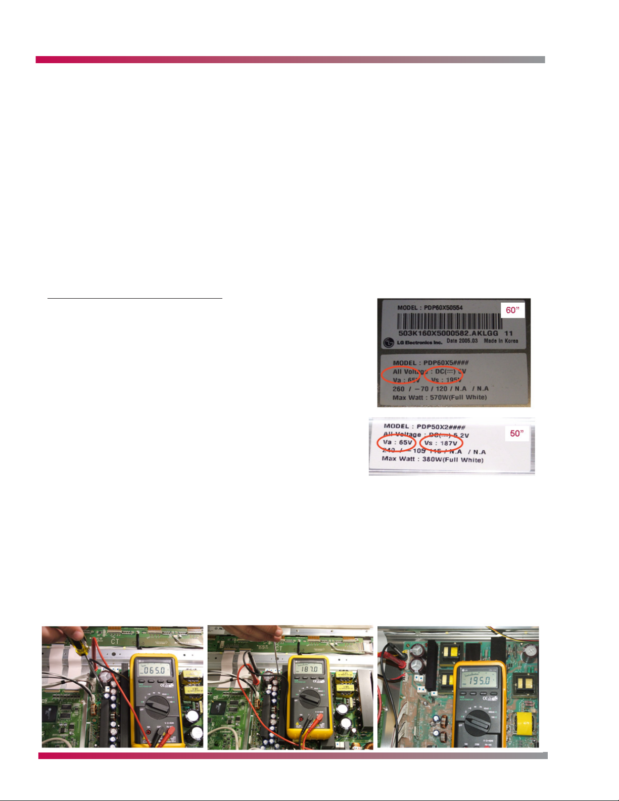
DISASSEMBLY
7) Reconnect the cable from the digital board connector P301, to the Digital VSC board connector
CN1300.
8) Reconnect the cable from Digital VSC board connector CN1700 to the Power Supply connector
P803.
9) Reconnect the cable from Analog / Tuner board connector P201 to the Power Supply connector
P802.
10) Reconnect the control panel cable to the Analog Tuner board P408 and P403, on the 60” model.
The 50” model only has connector
11) Use the nylon cable ties to secure all loose wiring. Inspect wiring for any pinched or damage
insulation and repair or replace if necessary.
This process completes the installation of the panel. The unit is ready to have AC power applied to the
set. The power supply Vs and Va run voltages must be checked and adjusted to the panel specifications.
The correct voltage settings are notated on an adhesive label placed on the backside of the panel.
VS AND VA VOLTAGE ADJUSTMENT
1) Apply power to the unit and turn it on. If the unit does not
operate correctly, check all connections and look for loose
wires that may have been missed or that have become
disconnected during the reassembly process.
2) Allow the unit to run for 5 minutes. This is to allow the set
to achieve operating temperature before checking the Vs
and Va run voltages. This step should be completed before
making adjustments to Vs and Va voltages.
3) Connect the positive ( + ) terminal lead of the digital multimeter to the Va pin of connector P805 and connect the
negative ( - ) terminal lead of the digital multi-meter to
the ground ( GND ) pin of P805.
4) Adjust variable resistor RV501 to match the Va voltage specification shown on the label attached
to the panel. ( Deviation: ±0.5v )
5) Connect the positive ( + ) terminal lead of the digital multi-meter to the Vs pin of connector
P805 and connect the negative ( - ) terminal lead of the digital multi-meter to the ground (
GND ) pin of P805.
6) Adjust variable resistor RV401 to match the Va voltage specification shown on the label attached
to the panel. ( Deviation: ±0.5v )
7) After confirming the Vs and Va run voltages, the set is ready to reassemble.
Plasma Training 78 Disassembly
Page 79

SOFTWARE UPDATES
SOFTWARE UPDATES
UPDATES VIA MEMORY CARD
Firmware can be updated using a memory card on newer PDP TVs that feature a memory card reader.
When a memory card is inserted, the TV will look for any firmware updates located on the card. If it
doesn’t find an update newer than the version on the TV, it displays the normal media menu for
displaying photos or playing music from the card.
Supported memory cards:
CHECK HARDWARE VERSION
Before updating the firmware, check the hadware version to
be sure it will support the firmware you wish to install. If
there are any hardware requirements, the documentation with
the firmware will list them. To open the diagnostics screen,
highlight the Cable icon in the user menu and then press the
zero 0 button three times.
The software version can also be obtained by pressing the
IN-START button on a service remote.
Plasma Training 79 Software Updates
Page 80

SOFTWARE UPDATES
FIRMWARE SPECIAL REQUIREMENTS
For some firmware releases, there are different versions for different model revisions. Check the model
suffix of the TV to determine which update to use. You will find the suffix on the back of the TV next
to “Product Code”. Make sure you use the correct file when doing any updates.
UPDATE INSTUCTIONS - NORMAL METHOD
1) Copy the Firmware update to the memory card. This has already been done for you if the card
came from LG Customer Service. The firmware file will have the file extension “.epk”. Only copy
the firmware update for your model TV.
2) Turn the TV on and insert the memory card into the TV. If the firmware on the card is newer than
the firmware in the TV, the following will be shown:
Current TV Software version: 3.08 (date: 5/5/2005)
The following new software is found in the memory card.
File: 42LP1DU_V313_rom.epk
- Main Software: 3.13
3) Press ENTER on the remote to begin the firmware update. The TV will restart automatically and
show the progress of the update. Do not remove the memory card or remove power from the
TV until complete.
Reading the file...Done
Main Software: Upgrading...22 Percent
4) The TV will show the following messages when the firmware update is complete:
Reading the file...Done
Main Software: Upgrading...Done
The software upgrade has been successfully completed.
Press ENTER to restart the TV now.
The TV will restart automatically in 14 seconds.
5) Press ENTER. After restarting, the TV is ready to use.
Plasma Training 80 Software Updates
Page 81

SOFTWARE UPDATES
UPDATE INSTUCTIONS - EXPERT METHOD
Expert Mode will allow any firmware version on the card to be loaded into the TV. This allows an older
version of the firmware to be loaded when needed.
1) Copy the Firmware update to the memory card. The firmware file will have the file extension
“.epk”. Only copy the firmware update for your model TV.
2) Turn the TV on and insert the memory card into the TV.
3) If a menu displays on the screen, exit out of that screen. Press the MENU button and highlight
(scroll down to) the Option menu. Press the MARK button 7 times and the expert mode screen
will appear.
TV Software Upgrade For Experts
TV Software Upgrade For Experts
[Current TV Version Information]
[Current TV Version Information]
- Main Software : 02.06.01(04/01/05)
- Main Software : 02.06.01(04/01/05)
- File System : 07.01
- File System : 07.01
- EDBMS : 01.0c
- EDBMS : 01.0c
The following software files are found in the memory card.
The following software files are found in the memory card.
Select the file you want to download to this TV.
Select the file you want to download to this TV.
Or, Press EXIT to cancel the upgrade.
Or, Press EXIT to cancel the upgrade.
APP: 02.04.01 FS VER: 07.01 DB VER: 01.0c
APP: 02.04.01 FS VER: 07.01 DB VER: 01.0c
APP_50PY2DR-UA_0401.EPK
APP_50PY2DR-UA_0401.EPK
BOOTROM.EPK
BOOTROM.EPK
APP_50PY2DR-UA_0301.EPK
APP_50PY2DR-UA_0301.EPK
APP_50PY2DR-UA_0225.EPK
APP_50PY2DR-UA_0225.EPK
APP_50PY2DR-UA_0124.EPK
APP_50PY2DR-UA_0124.EPK
4) Use the arrow keys to select the firmware update to install. Press OK and follow the prompts.
5) When the update is complete, press ENTER to restart the TV. After restarting, the TV is ready to
use.
Plasma Training 81 Software Updates
Page 82

SOFTWARE UPDATES
FIRMWARE UPDATES VIA SERIAL CABLE
USING THE TERATERM SOFTWARE
There are currently two methods used to updatethe firmware on LG PDPs using TeraTerm. The most
common is listed first. Refer to the Service Bulletin for which method should be used. Both require a
null modem cable.
Note: Not all female to female serial cables are null modem cables. Null modems cables will have
some type of marking on them like “NM”...or actually have “Null Modem” stamped on them.
INSRUCTIONS FOR MOST PDPS (AND LCDS)
1. If you have already TeraTerm software and if the software works on your laptop, go to step 5.
2. If you don’t have TeraTerm software, download TeraTerm software from:
http://www.tucows.com/preview/195282.html
3. Unzip the file (TeraTerm) from above site.
4. Install TeraTerm software on your computer.
5. Unplug the power on the TV set.
6. Turn your laptop PC on.
7. Connect null modem cable between laptop computer and TV sets using serial port.
8. Execute “TeraTerm” software in you laptop computer
9. ”Serial Port” on TeraTerm Go to “Setup”
10. Set the port number of your Laptop (Usually 1 or 2), Baud rate “115200”, Data “8 bit”, Parity
“none”, Stop “1bit”, Flow control “none”, Transmit delay “0 msec/char 0msec/line”, and click
“OK”. (If you don’t have any serial port on your laptop, you need a USB to serial cable connector.
You can get one from a computer store.)
11. Keep pressing the “1” key on your laptop’s keyboard and plug in the power on the TV.
12. Once power is on the TV set, release the “1” key on your laptop’s keyboard after you see the
message (release “1” key) on your laptop.
13. Type “1” on your laptop’s keyboard and hit “enter” key. ”Send file” on TeraTerm.
14. Go to “File”
15. Check “binary” in the small box at the bottom of the screen..
16. Select appropriate file for downloading.
17. Hit “enter” key on the laptop’s keyboard.
18. Wait for download completion
19. After download completion, the TV set will automatically tun off and on. If not, unplug the
power on the TV set and reapply power.
20. Download procedure is done!!
Plasma Training 82 Software Updates
Page 83

SOFTWARE UPDATES
ALTERNATE DOWNLOAD INSTRUCTIONS
1. Turn on your laptop PC
2. Connect a null modem serial cable between laptop computer and TV.
3. Turn on TV.
4. Change baud rate of TV to “115200” using instart key on “adjust remocon”
5. Execute “TeraTerm” software in your laptop computer.
6. Go to “Setup” then “Serial Port” in TeraTerm.
7. Set the port number of your Laptop (Usually 1 or 2), Baud rate “115200”, Data “8 bit”, Parity
“none,” Stop “1bit,” flow control “none,” Transmit delay “0 msec/char 0msec/line,” and click
“OK,”
8. Press the enter key several times to check the laptop communication with the TV. If the cursor
moves down, the laptop is communicating with TV.
9. Type the model # (This has to be the factory model #)
10. Hit “d” on your laptop keyboard and hit “enter” key on your laptop keyboard
11. Hit “f0” (F and Zero) on your laptop keyboard and hit “enter” key on your laptop keyboard
NOTE: Read the items in the menu. They may differ by model and production series, thus f0 is correct
for some models but not others. Just keep in mind you are using a serial port and wanting to
upgrade the firmware.
12. Hit “10” (1 and Zero) on your laptop keyboard and hit “enter” key on your laptop keyboard.
NOTE: Read the items in the menu. They may differ by model and production series, thus 10 is correct
for some models but not others. Just keep in mind you are using a serial port and wanting to
upgrade the firmware.
13. Go to “File” then “Send file” on TeraTerm Select the file “DU42PY 10X rom.img” for downloading.
14. Hit “enter” on the laptop’s keyboard.
Plasma Training 83 Software Updates
Page 84

SOFTWARE UPDATES
FIRMWARE UPDATES VIA MDS
1) Start > Program > MDS > MDS Click
* Press power on the service remote before you start the MDS program.
2) Click on OK.
3) Item 1 below Select Correct Model
4) Item 2 below Open Browse & Select source file (ROM) is usually the only file needed to upgrade
the software.
5) Item 3 below click this box to select this comunication port.
Plasma Training 84 Software Updates
Page 85

SOFTWARE UPDATES
Plasma Training 85 Software Updates
Page 86

SOFTWARE UPDATES
USING LGIDS AND GPROBE
1. On your desktop right click on My Computer or
access My Computer from the start menu.
2. Left click on Properties.
3. Left click on the Hardware tab.
4. Left click on (Device Manager...) Check the
Availability of Serial Port under “Ports” as
Communications Port (COM1) as shown in the
figure.
1. After downloading the program from GCSC. Install
\42PM1M-42PM3MV\GProbe5.1.0.18.exe
2. Run the EXE file and the install process will begin and an icon
will be placed on your desktop.
3. GProbe5 can be use by double clicking on the icon as shown in
the figure.
Opening GProbe will appear as below:
Plasma Training 86 Software Updates
Page 87

Select the GProbe connection by clicking the icon as below:
Gprobe
Connection
Setup
SOFTWARE UPDATES
Plasma Training 87 Software Updates
Page 88

SOFTWARE UPDATES
Left click on the Connection Settings icon and
check the settings tab for Port under
“Connection Tab”as shown in figure.
Click the Serial tab for checking other
configurations as shown in figure. Port: COM1, Baud
Rate: 115200.
Plasma Training 88 Software Updates
Page 89

SOFTWARE UPDATES
Install \42PM1M-42PM3MV\LGIDS_Ver[1].83\Setup.exe. After successful installation
create the shortcut on the desktop by clicking on Start, scrol up to programs, move
the curser to the right and scrol till you see (LGIDS), to the right you will see
. When you right click on this icon scroll up to (Send To) and left
click on the (Desktop (create shortcut)). You will now have a link on your desktop
to the LGIDS software. . When you open this program you will see.
Now select the new configurations.
Model: In this case it is Hurricane
as shown in the figure.
Plasma Training 89 Software Updates
Page 90

SOFTWARE UPDATES
If “COM1Port” is
connected it will display
the message under
Communication as:
Connection Port: COM1
Baud Rate: 115200
Now select the new configurations.
ROM Download: Batch file :
CORTEZ_2M.flm as shown in the figure.
Follow this same procedure with the
Ram and Flash files.
Clock here to locate the batch file
you want to load into the unit.
After locating the path of all the three
files (Batch, Ram and Flash), set the
unit up as shown.
Press Tilt Key from SVC Remocon and click on Download for successful download of software in TV.
After Successful downloading of the software in the TV:
Switch Off Main Power Supply to
the T.V Sets for more than 5
seconds and again Switch On the
Main Power Supply, TV is in
Standby mode(D.C Power Off).
Press Power Key from SVC
Remocon to turn the TV on.
Press ADJ Key from SVC Remocon
for Software Version Check.
42PM1M_UC_Ver3.06…….
42PM3MV_UC_Ver3.04
Cortez Version 3.21
Hudson Version 3.19
Panel Used 2 Hr.
Tool Option 41
Area Option 20
Option1 106
Option2 23
Option3 2
Option4 128
System Control
Panel Control
Screen Control
Fan Control
BlkLine Detector
Power-off History
XSTUDIO Control
STATION
MF – 056A
System Control
STATION
System 4 - SYS
OverScan 5 %
OrbitPixel 2
Orbit Step 2
OrbitTime 120 Sec.
Inv. Time 30 Min.
RS-232 Host Gprobe
Baud Rate 115200 bps
Now Press IN-STOP key on the
SCV Remocon to complete the Job.
Plasma Training 90 Software Updates
Page 91

CONTROL PCB SOFTWARE UPDATE
Control PCB Software Update
SOFTWARE UPDATES
Jig
Lift
Speaker
Connector P204
AC power cable
retainer.
P100
• Once the back has been removed.
• Remove the screws holding the Digital/Tuner PCB assembly and AC power switch to the TV.
• Disconnect P151from Z-Sus and P151 from Y-Sus.
• Remove the AC power cable from the retainer.
• Disconnect the cable to the front keyboard assy.
• Lift the lower end of VSC/Tuner PCB assembly up after disconnecting P100 from the tuner PCB and
the speaker P204 from the tuner PCB.
• Route the cable from the jig to the control PCB under the mount support and connect it to P101
(found in the upper left by the power connector) on the control PCB.
• Connect the other end to the EPP port on the jig with the jig OFF.
• Keep the jig away from any PCB to prevent damage to the jig or the PCB.
NOTE:
To Acquire this jig call technical support for model and problem evaluation. This jig will have to be
returned to LG.
Plasma Training 91 Software Updates
Page 92

SOFTWARE UPDATES
Mount support
Front Keyboard Connector
Selecting the correct file
P151
P204
P100
AC Power retainer
NOTE::
under the fan.
This connector is
Connect the cable from the jig here on the control PCB.
This ID will be found on a label on the Control PCB Be sure the panel model you select on the jig
matches the label on the control board. Verify that the version you have in the jig is a later version
than what is on the label. EX: 05B would be later than 05A or 04X.
Plasma Training 92 Software Updates
Page 93

File location
File location
SOFTWARE UPDATES
Panel model
Rom version
Panel model
Rom version
The File location will not appear on the label on the control PCB.
• Turn the power to the jig ON
• Use the MODEL up or down to select the correct file.
*To use the MODEL up/down keys. Press either key for 3 seconds and release the key, you will see
the model id disappear and only the number will be shown in the upper left.
*Quickly use the up/down keys to scroll to the file in location number 1. The file will load after a
few seconds. The file name (42X2DN05B) appears in the screen on the jig.
NOTE: To use any key on the jig you must hold the key down for at least 3 seconds.
•Apply AC power to the jig with the switch on the jig OFF and apply AC
to the TV. Only one LED will be lit.
Digital PCB
•Press the main AC power switch to the ON position on the TV. These
additional LED’s will be lit. If the TV is in the ON state when you connect
AC, the unit will turn itself on. Turn on the jig.
Plasma Training 93 Software Updates
Page 94

SOFTWARE UPDATES
•When the TV is in the ON state these additional LED’s will be lit.
Control PCB
Connector to JIG (P101)
What will be seen during the update.
Press and hold the (AUTO) button for 3 seconds and release the (AUTO) button.
Within a few seconds the display will indicate (ERASING) and the LED will be
flashing green.
The display will next display (WRITING) and the LED will be blinking.
The display will then display (VERIFYING) and the LED will be blinking.
This LED will be blinking
If the update was successful the display will indicate (OK) and the LED
will be on.
Plasma Training 94 Software Updates
Page 95
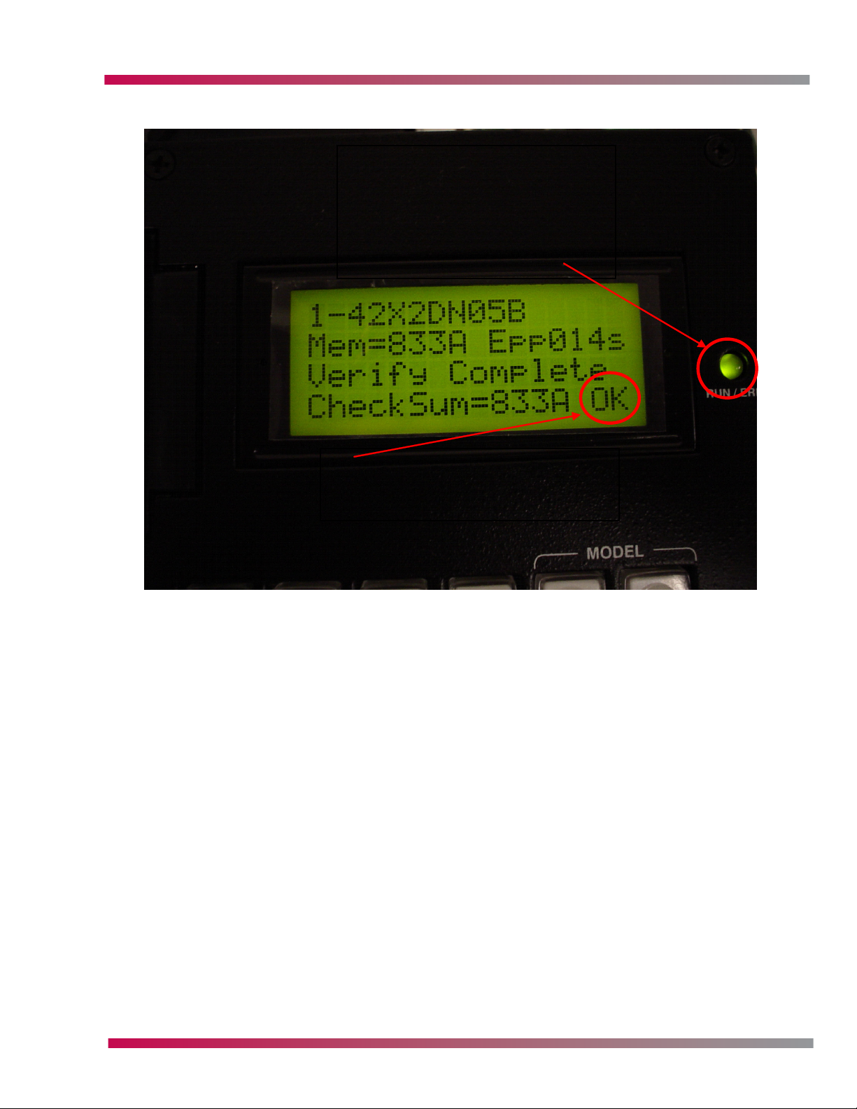
If the update is sucessful the display will appear as below:
This light will blink
during update and
become solid when
done if successful.
SOFTWARE UPDATES
OK will be displayed
after Verify is completed.
• Switch the TV OFF and remove AC power.
• Switch the jig OFF and remove AC power.
• Remove the cable from the jig to the control PCB from P101 on the PCB.
• Reconnect P151 Y-SUS, P151 Z-SUS, P100 and P204 on the tuner PCB make sure AC cables are
firmly connected to the AC switch and SMPS connectors are seated and all cables are in their
retainers.
• Remount Digital/Tuner PCB mount assembly to the TV.
Plasma Training 95 Software Updates
Page 96

CABLECARD S-CARD
CABLECARD
DIGITAL CABLE READY (DCR)
A “plug-and-play” DTV is a television that you can plug directly into your cable system and receive
analog and most digital cable services without the need for a set-top box. The cable and consumer
electronics industries have dubbed these types of televisions “digital cable ready” or “DCR.”
Digital plug-and-play will not work quite like analog. For digital plug-and-play, you’ll probably need
to get a security card (also known as a CableCARDTM) from your local cable operator. The security card
will permit you to watch scrambled programming and premium services, to which you’re subscribed.
A CableCARD device is A PCMCIA card distributed by cable operators and inserted into a DCR TV(Host)
to enable premium services, also called “Card” and “Point of Deployment(POD) module”. It provides
authorization, CA (Conditional Access) decryption and CP (Copy Protection) encryption functions for
the consumer’s DCR TV.
Antenna
TV Station/
TV Station/
Network
Network
Satellite Dish
Satellite Dish
Fiber
Fiber
Antenna
Cable Headend/
Cable Headend/
“Plant”
“Plant”
Using Cable line, bi-directional communication is possible
Using Cable line, bi-directional communication is possible
Node
Node
Node
Node
House
House
House
House
CEA-NCTA AGREEMENT
• Signed Dec 19, 2002
• An agreement between cable operators and the consumer electronics industry
• How to offer digital programming over cable lines to current and future digital televisions
without the need for a set-top box
• “Unidirectional” cable-ready digital television sets (called UDCP or UDRD)
* Conditional access mechanism
* Separate CableCARD (POD) card
* Only receive information from the headend (one-way)
• Cable industry: Comcast, Cox, Time Warner, etc. (8 companies)
• CE industry: Philips, Panasonic, Zenith, Samsung, Sony, etc (14 companies)
• First Verification started Feb 2004 (VW18) based on PICS/ATP
Plasma Training 96 CableCARD
Page 97

CABLECARD S-CARD
• DCR TV can receive:
* Off-air HD/HD through cable
* Off-air/Cable Analog & Digital
• But, DCR TV doesn’t support:
* VOD, Impulse PPV
* EPG service provided by MSO
TERMS
CEA: Consumer Electronics Association
NCTA: National Cable & Telecommunications Association
POD: Point-Of-Deployment
UDCP: Uni-Directional Cable Product, UDRD : Uni-Directional Receiving Device
DCR: Digital Cable Ready
PICS: Protocol Implementation Conformance Statements
ATP: Acceptance Test Plan
PPV: Pay Per View
Off-air: Terrestrial retransmission through cable
Inband tuner: FAT tuner
OOB tuner: FDC tuner
CA: Conditional Access
CP: Copy Protection
OOB: Out Of Band
RDC: Reverse Data Channel
OOB: Out of Band
FDC: Forward Data Channel
FAT: Forward Application Transport
PSI: Program Service Information
SI: Service Information
Clear channel: Any channel that is not scrambled or encripted. Thus the customer will be able
to recieve these channels with only basic cable service.
Scrambled/Encripted Channels: Channels that are scrambled or encripted and require additional
equipment to recieve these channels. EX: Cablecard or cable box.
VENDORS
• CableCARD (POD) vendors:
Motorola, Scientific Atlanta, SCM/NDS
• Cable HeadEnd vendors:
Motorola, Scientific Atlanta, Harmonic
• Cable MSO (Multiple System Operators)
Comcast, Time Warner, Charter, Cox, Adelphia, Bright House, Mediacom, Insight, CSC Holdings,
Cable One, Advance/Newhouse, etc.
Plasma Training 97 CableCARD
Page 98

CABLECARD S-CARD
DCR ARCHITECTURE
Cable
In
Tuner
Inband
6 MHz
OOB
QPSK
Demod
NTSC
QAM
QPSK
A/V
Decode
AVD
CP Decrypt
& Demux
Multimedia
Processor
-NTSC coder
-Graphics
processor
SPTS
Video Out
Ch-3/4 Out
S-Video Out
L/R Out
AC-3 Out
HDMI/DVI Out
1394A + CP
CA
Decrypt
& CP
Encrypt
(POD)
CPU
- User I/F
- Functions
-Apps
- VBI decode
-etc.
The OOB (Out Of Band) tuner runs all the time, locked to the frequency which it is given by the
Cablecard. The data from the Headend should be on this frequency. If it is not, the tuner wil not see
the data nor will the Cablecard. EX: If the cablecard tells the unit to tune to 104.20Mhz. The unit will
tune to 104.20Mhz and not search for other frequencies. If the MSO (Multi System Operator) has the
cards prgrammed to give the unit a list of frequencies, the unit will search that list of frequencies to
find the data and then lock. If the data is on 104.25Mhz, neither the unit nor card can get the data
needed to receive a channel list and an authorization list , the CP and decrypt data. As a result, the
unit will not be allowed to tune premium channels.
HOST-CABLECARD INTERFACE
The data communication to and from the Cablecard and unit is encrypted. The Host (Unit) and POD
(Cablecard) share a buffer so that the data from the headend is never lost. Some of the buffer is in
the POD and some is in the host.The authorization list, CP data, Decrypt data and some other data is
updated every 10 -20 seconds. This allows the cable company to add, remove, and rearrange channels
as needed and the Cablecard is updated within seconds without the customer having to run EZ Scan
to load new channels added to their lineup. The data from the headend is at regular intervals and can
fluctuate in timing. This causes the data to flow at a higher rate at times and a lower rate at other
times depending on other tasks the headend is performing on the system. The comunication between
the POD and host is a two way relationship. While the communication between the Cablecard and
headed is only one way, from the headend to the card.
Plasma Training 98 CableCARD
Page 99

CABLECARD S-CARD
Protected by
Protected by
Cable System,
Cable System,
Conditional
Conditional
Access System
Access System
DCR(Host)
QPSK Tuner
& Demod
QAM Tuner
& Demod
CA-Encrypted Stream
CableCARD
CA Decrypt &
CP Encrypt
CP
Decrypt
Clear Stream
Protected by
Protected by
CableCARD--
CableCARD
System
System
CP-Encrypted Stream
1394 + 5C
MPEG2
Demux
& Decode
CPU
User I/F
OS, Memory
CP
CP
Most but not all, CADTV (Cable Digital Television) channels are scrambled and or encrypted. Therefore
decryption is a part of a premium package the customer pays for. There are a few channels the cable
company has to provide as open channels. This allows the customer who purchases an HD ready TV
that is capable of processing QAM to recieve a few HD channels thru the cable system. In LG units
there are two ways the channels are displayed, as 2 part channels (EX: 107-1) and as single part
channels EX: 107. With the Cablecard inserted the CADTV map will show only single part channels.
Without the card installed the CADTV map will show two part channels. Due to this it will be in the
ASC’s best intrest to have a constantly updated channel lineup showing which are scrambled and
which are open channels for all the headends in the area you service product. A good relationship
with the local cable company is crucial to this so you are kept up to date with fast changing channel
lineups. This can prevent you from trying to repair a product that is not defective. EX: The customer
complains they no longer recieve CH 186 which was Discovery HD a scrambled channel. The real cause
is the headend moved that channel to CH 205 and CH 186 is no longer in the channel map. All this
occurs through the OOB channel.
Plasma Training 99 CableCARD
Page 100

CABLECARD S-CARD
IN-BAND/OOB SPECIFICATION
In Band
Analog FAT/QAM
5 MHz
OOB OOB
54Mhz
42Mhz
1. DCR doesn’t use this band because DCR has
Uni-directional, downstream functionality only.
70Mhz 130Mhz 864Mhz450/550Mhz
OOB RDC
Upstream
QPSK
Bit Rate : 1.544/2.048/3.088Mbps
OOB FDC
Downstream
QPSK
Bit Rate : 1.544/2.048/3.088Mbps
1. HeadEnd Sends Cable Channel Info (SI)
through this band
MPEG-2
RS Coding
Interleaving
Trellis Code 64/256QAM
Frequency
CABLECARD AUTHORIZATION & VALIDATION PROCESSES
• In order to activate CA service (called low-value service) and to receive Cable channel map,
“Authorization process” is needed.
* Serial number and CableCARD ID are needed.
* During this process, CableCARD reset may occur.
* After this process is finished successfully, user can navigate cable channel map & can watch
CA Encrypted services to which the user subscribes.
• In order to activate additional CP services (called high-value service), a “Validation process” is
needed.
* Host/CableCARD ID is needed.
* HeadEnd sends Validation message through OOB channel.
* After Validation message is received by the CableCARD, the user can watch CP Encrypted
services also.
DCR FUNCTIONALITIES
• Conditional Access Function
• Copy Protection Function
• Cable menu & MMI (Man Machine Interface) Function
• Digital Certificates
• CableCARD reset Function
• EAS (Emergency Alert System) Function
• Host Diagnostics Function
• CableCARD Firmware Upgrade Function
• Error Reporting Function
Plasma Training 100 CableCARD
 Loading...