How it Works
Log In / Sign Up
Buy Points
How it Works
FAQ
Contact Us
Questions and Suggestions
Users
LG
Loading...
#
60PS4000-ZA
60PS40FC
60PS40FD-AA
60PS40FR
5
60PS60
6
60PS60C
5
60PS60FD-AA
60PS60UA
60PS70
32
60PS7000
10
60PS7000-ZA
2
60PS70FD
2
60PS70FD-AA
2
60PS70UG
60PS8
60PS80
37
60PS8000
11
60PS8000-ZA
2
60PS8032LH50
60PS8088
60PS80BR
7
60PS80BR-TA
60PS80FD-GA
60PS80R-TA
60PS80-UA
2
60PS8 Series
60PT100C-WA
2
60PT100N
2
60PT1RF
60PT1RF-TA
2
60PT200N
60PV2
60PV25
2
60PV250
21
60PV250A
60PV250A-ZA
60PV250K
60PV250K-ZA
60PV250N
4
60PV250N-ZA
60PV250-TB
2
60PV250-ZA
60PV25 Series
2
60PV400
3
60PV430
4
60PV450
6
60PV450C
5
60PV450UA
60PV490
5
60PV490-UC
2
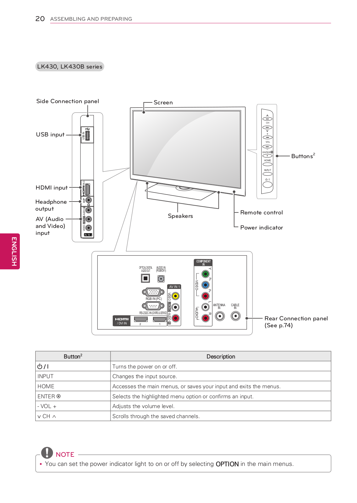
60PV550B
2
60PV550E
2
60PV550U
4
60PV55OU
60PX9
60PX950
7
60PX950N
4
60PX950UA
60PX960
2
60PX990
60PY2
60PY2D
3
60PY2D-AB
60PY2DR
12
60PY2DRH
2
60PY2DRH-UA
2
60PY2DR-UA
6
60PY2R
29
60PY2RH
60PY2RH-MC
60PY2R-MC
2
60PY2R-TB
60PY2R-ZB
60PY3D
18
60PY3DF
10
60PY3DF-AA
60PY3DF Series
2
60PY3DF-UA
3
60PY3DF-UJ
6
60PY3RF
11
60PY3RF-TB
60PZ200
6
60PZ200UA
60PZ25
60PZ250
13
60PZ250A
2
60PZ250N
2
60PZ250N-ZB
60PZ250T
2
60PZ250T-ZB
60PZ25 Series
60PZ540
2
60PZ55
2
60PZ550
26
60PZ550A
60PZ550T
60PZ550-TA
60PZ550-TC
60PZ55 Series
2
60PZ57
Loading...
Loading...
Nothing found
60PV550B
Owner's Manual
104 pgs
22.63 Mb
0
User manual [pt]
127 pgs
20.41 Mb
0
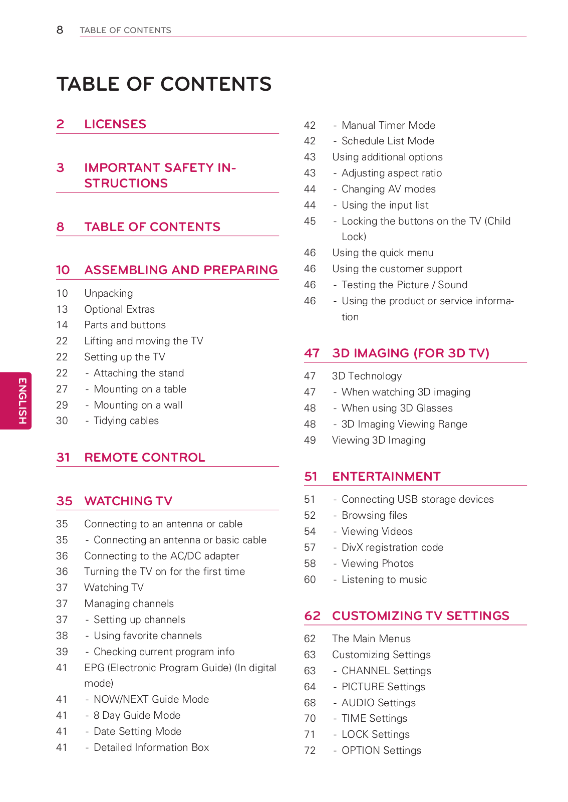
Table of contents
Loading...
LG 60PV550B User manual [pt]
...
LG User manual [pt]
Download
Specifications and Main Features
Frequently Asked Questions
User Manual
Download
Loading...
+
97
hidden pages
Unhide
You need points to download manuals.
1 point = 1 manual.
You can buy points or you can get point for every manual you upload.
Buy points
Upload your manuals
 Loading...