

LG 60PT1RF-TA User Manual

Please read this manual carefully before operating
your set.
Retain it for future reference.
Record model number and serial number of the set.
See the label attached on the back cover and quote
this information to your dealer when you require
service.
PLASMA TV
OWNER’S MANUAL
PLASMA TV MODELS
6600PPTT11RRFF
**
PP//NNOO:: MMFF LL 3377445577771155 ((00770099--RREEVV0000))
PPrr iinntteedd iinn KKoo rr eeaa

1
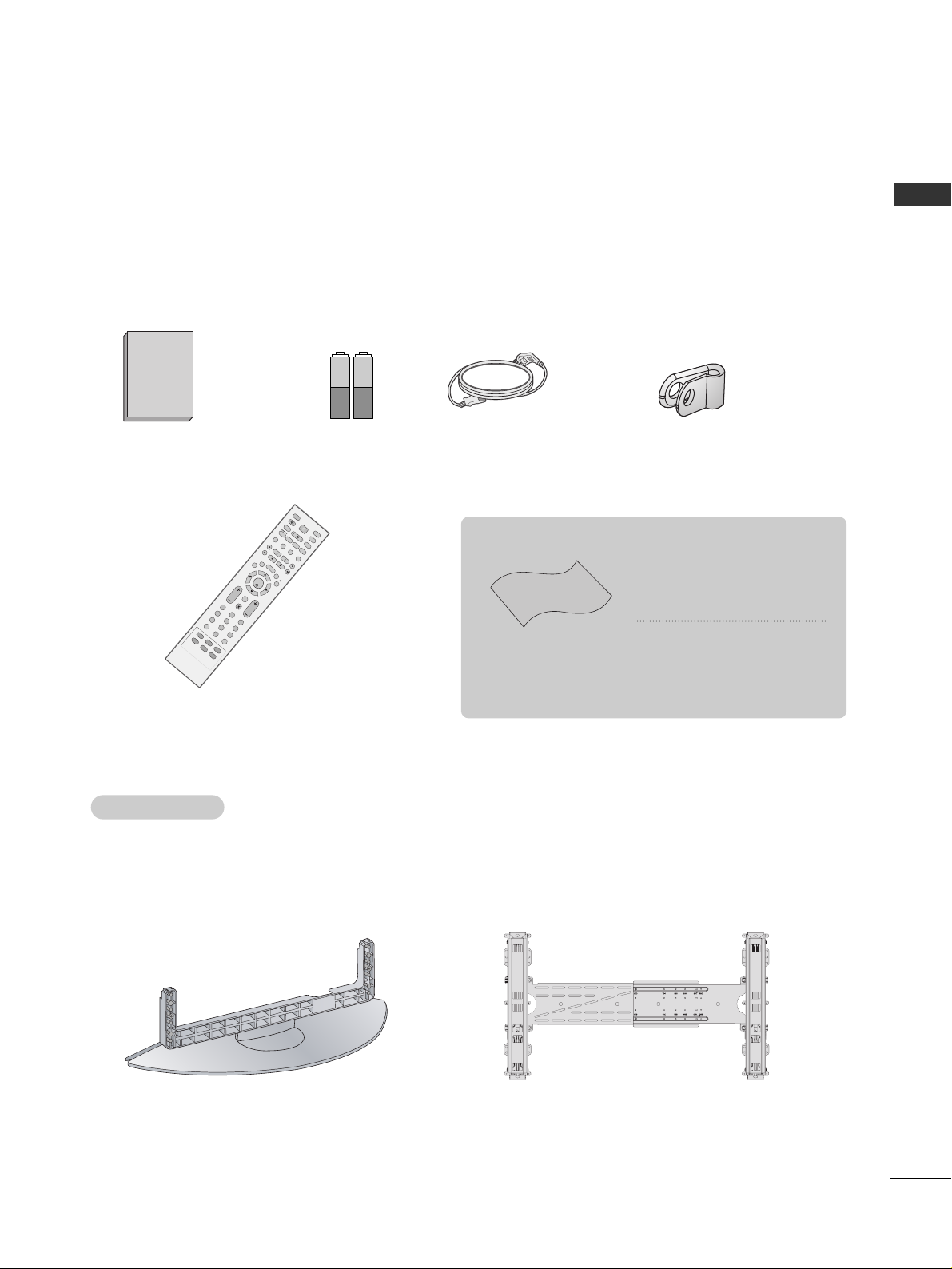
ACCESSORIES
Ensure that the following accessories are included with your TV. If an accessory is missing, please contact the
dealer where you purchased the product.
ACCESSORIES
Owner’s Manual
Batteries
Remote Control
Power Cord
Polishing Cloth
Polish the screen with the cloth
*Slightly wipe stained spot on the
exterior only with the cleansing
cloths for the product exterior if
there is stain or fingerprint on surface
of the exterior.
Do not wipe roughly when removing
stain. Please be cautious of that
excessive power may cause scratch
or discoloration.
Holder
(Refer to p.7)
Optional extras can be changed or modified for quality improvement without any notification new optional extras can be added.
Contract your dealer for buying these items.
Option Extras
Option Extras
Tilt wall mounting bracket
Desktop stand
Owner's
Manual
V
O
L
P
R
123
45
7
O
K
I
N
P
U
T
M
O
D
E
T
V
T
V
D
V
D
R
A
T
IO
E
X
IT
V
O
L
POSITION
P
R
P
I
P
S
L
E
E
P
L
I
S
T
Q.VIEW
I
/
I
I
M
E
N
U
S
IZ
E
V
C
R
P
IP
P
R
P
I
P
P
R
+
P
IP
IN
P
U
T
P
O
W
E
R
123
456
789
0
S
I
M
P
L
I
N
K
IN
P
U
T
S
W
A
P
COMP1
R
G
B
A
V
1
C
O
M
P
2
H
D
M
I
1
/
2
A
V
2
MUTE
BRIGHT
FAV
MUTE
FAV
2
CONTENTS
CONTENTS
PICTURE CONTROL
Watching PIP(Picture-in-Picture) .............................44
Picture Size (Aspect Ratio)Control.........................46
Preset Picture Settings
- Picture Mode-Preset............................................48
- Auto Colour Tone Control(Warm/Medium/Cool)
49
Manual Picture Adjustment
- Picture Mode-User Option................................50
- Colour Tone - User Option ...............................51
-
Picture Improvement Technology
...................52
Advanced - Cinema......................................................53
Advanced - Black(Darkness) Level...........................54
Picture Reset..................................................................55
Demo .................................................................56
Image Sticking Minimization(ISM) Method...........57
Low-Power Picture Mode............................................58
WATCHING TV /PROGRAMME CONTROL
Remote Control Key Functions.................................28
Turning on the TV....................................................... 30
Programme Selection ................................................. 30
Volume Adjustment......................................................30
On Screen Menus Selection and Adjustment.......31
Auto Programme Tuning............................................ 32
Manual Programme Tuning ....................................... 33
Fine Tuning.....................................................................34
Assigning a Station Name ..........................................35
Booster............................................................................36
Programme Edit ........................................................... 37
Favourite Programme.................................................. 38
Calling the Programme List....................................... 39
Input Source Selection ...............................................40
................................................................. 41
Key lock.......................................................................... 43
PICTURE CONTROL
WATCHING TV / PROGRAMME CONTROL
AACCCCEESSSSOORRIIEESS
.....................................................1
PREPARATION
Front Panel Controls..................................................... 4
Back Panel Information ................................................ 5
Desktop Pedestal Installation ..................................... 6
Wall Mount: Horizontal installation .......................... 7
Power cord Arrangement............................................. 7
Antenna Connection..................................................... 8
EXTERNAL EQUIPMENT SETUP
HD Receiver Setup .........................................................9
DVD Setup..................................................................... 12
VCR Setup ..................................................................... 15
Other A/V Source Setup ........................................... 18
PC Setup .........................................................................19
- Screen Setup for PC Mode................................22
AV Output Setup ........................................................ 26
External Stereo Setup ................................................ 27
PREPARATION

3
CONTENTS
SOUND & LANGUAGE CONTROL
Preset Sound Settings - Sound Mode ....................59
Sound Setting Adjustment - User Mode ...............60
Auto Volume Leveler....................................................61
Balance ............................................................................62
TV Speakers On/Off Setup .......................................63
I/II
- Stereo/Dual Reception.......................................64
- NICAM Reception ................................................65
- Speaker Sound Output Selection....................65
On-Screen Menu Language Selection
...................... 66
APPENDIX
Troubleshooting............................................................74
Maintenance .................................................................76
Product Specifications ................................................77
Programming the Remote Control ........................ 78
IR Codes .........................................................................80
External Control Through RS-232C........................82
TIME SETTING
Clock Setting..................................................................67
Auto On/Off Timer Setting .......................................68
Sleep Timer Setting......................................................69
Auto Shut-off Setting...................................................70
TELETEXT
Switch On/Off ..............................................................71
SIMPLE Text....................................................................71
TOP Text .........................................................................72
FASTEXT .........................................................................72
Special Teletext Functions..........................................73
4
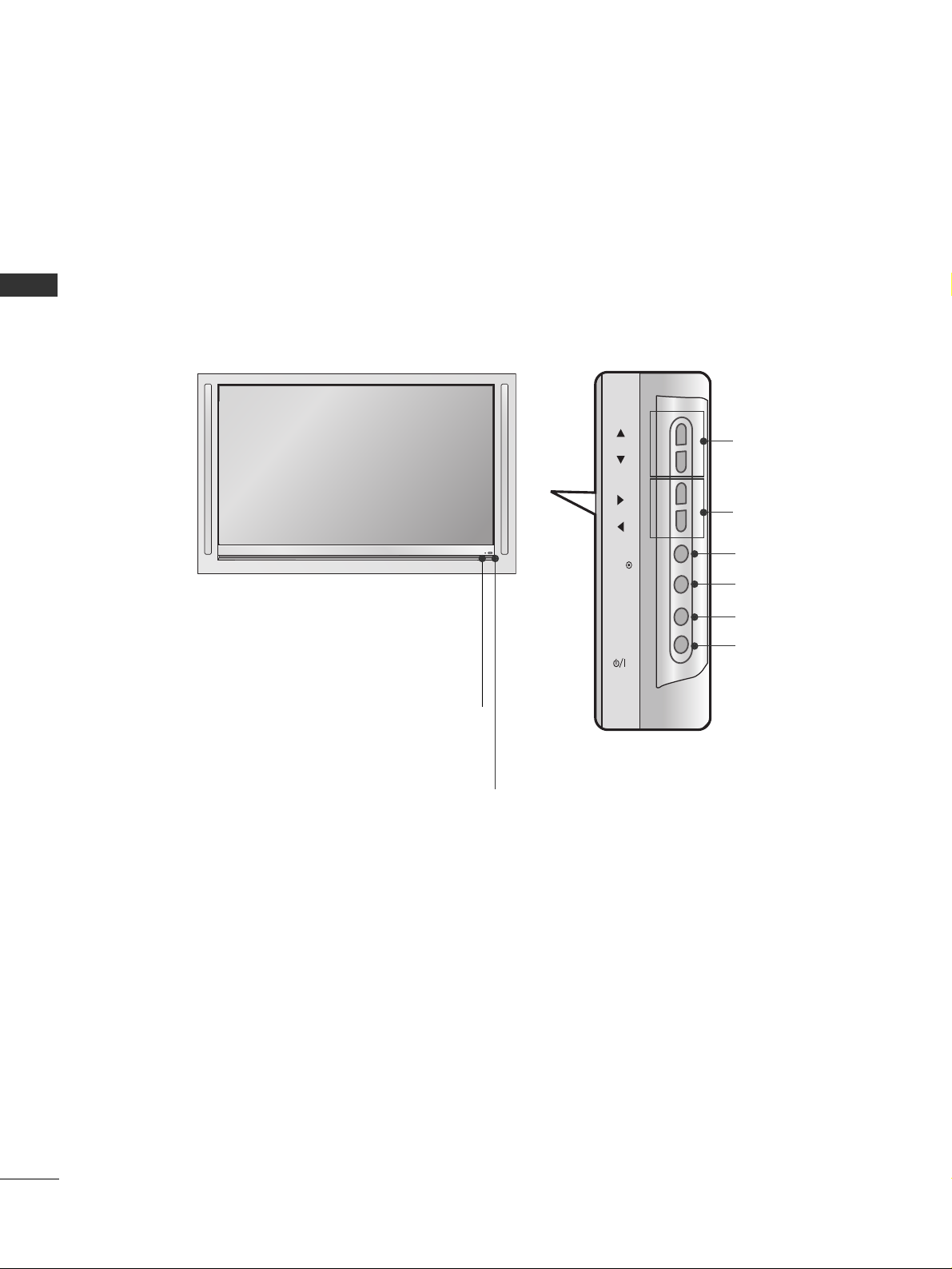
FRONT PANEL CONTROLS
PREPARATION
PREPARATION
■
This is a simplified representation of the front panel. Here shown may be somewhat different from your TV.
■
The external appearance of the set has an inherent character(annual ring, wood grain, knar) of wood.
■
If your product has a protection film attached, remove the film and then wipe the product with a polishing
cloth.
Power/Standby Indicator
• illuminates red in standby mode.
• illuminates green when the set is switched on.
Remote Control Sensor
PROGRAMME Buttons
VOLUME Buttons
OK Button
MENU Button
INPUT Button
POWER Button
PR
VOL
OK
MENU
INPUT

5
PREPARATION
BACK PANEL INFORMATION
■
This is a simplified representation of the back panel. Here shown may be somewhat different from your TV.
HDMI/DVI1, HDMI2 Input
Connect a HDMI signal to HDMI IN.
Or DVI(VIDEO)signal to HDMI/DVI port with DVI
to HDMI cable.
RGB/Audio Input
Connect the monitor output from a PC to the
appropriate input port.
Audio/Video Input (AV IN 1)
Connect audio/video output from an external
device to these jacks.
AV Output
Connect second TV or monitor to the AV OUT
socket on the set.
Antenna Input
Connect over-the-air signals to this jack.
Component Input 1/2
Connect a component video/audio device to
these jacks.
Variable Audio Output
Connect an external amplifier or add a subwoofer
to your surround sound system.
RS-232C Input
(CONTROL&SERVICE)Port
Connect the serial port of the control devices
to the RS-232C jack.
Power Cord Socket
This TV operates on an AC power. The voltage is
indicated on the Specifications page. Never
attempt to operate the TV on DC power.
1
2
3
4
5
6
7
8
9
9
S-Video Input
Connect S-Video out
from an S-VIDEO device.
Audio/Video Input
Connect audio/video
output from an external
device to these jacks.
AV IN 2V IN 2
L/L/MONOMONO
R
AUDIOAUDIO
VIDEOVIDEO
S-VIDEOS-VIDEO
AV IN 2
L/ MONO
R
AUDIO
VIDEO
S-VIDEO
HDMI IN
HDMI/DVI IN
ARIABLE
AUDIO OUT
RGB IN
COMPONENT IN
V IN 1
V OUT
L/
MONO
AUDIO
VIDEO
2
1
4
3
5
7
6
8
HDMI/DVI IN
1
2
1
COMPONENT IN
VIDEO
HDMI IN
2
AUDIO
RGB
(PC)
RGB IN
AUDIO
(RGB/DVI)
RS-232C IN
VARIABLE
AV IN 1
(CONTROL&SERVICE)
VIDEO
MONO
L/
AUDIO
R
AUDIO OUT
AV OUT
ANTENNA
IN
6
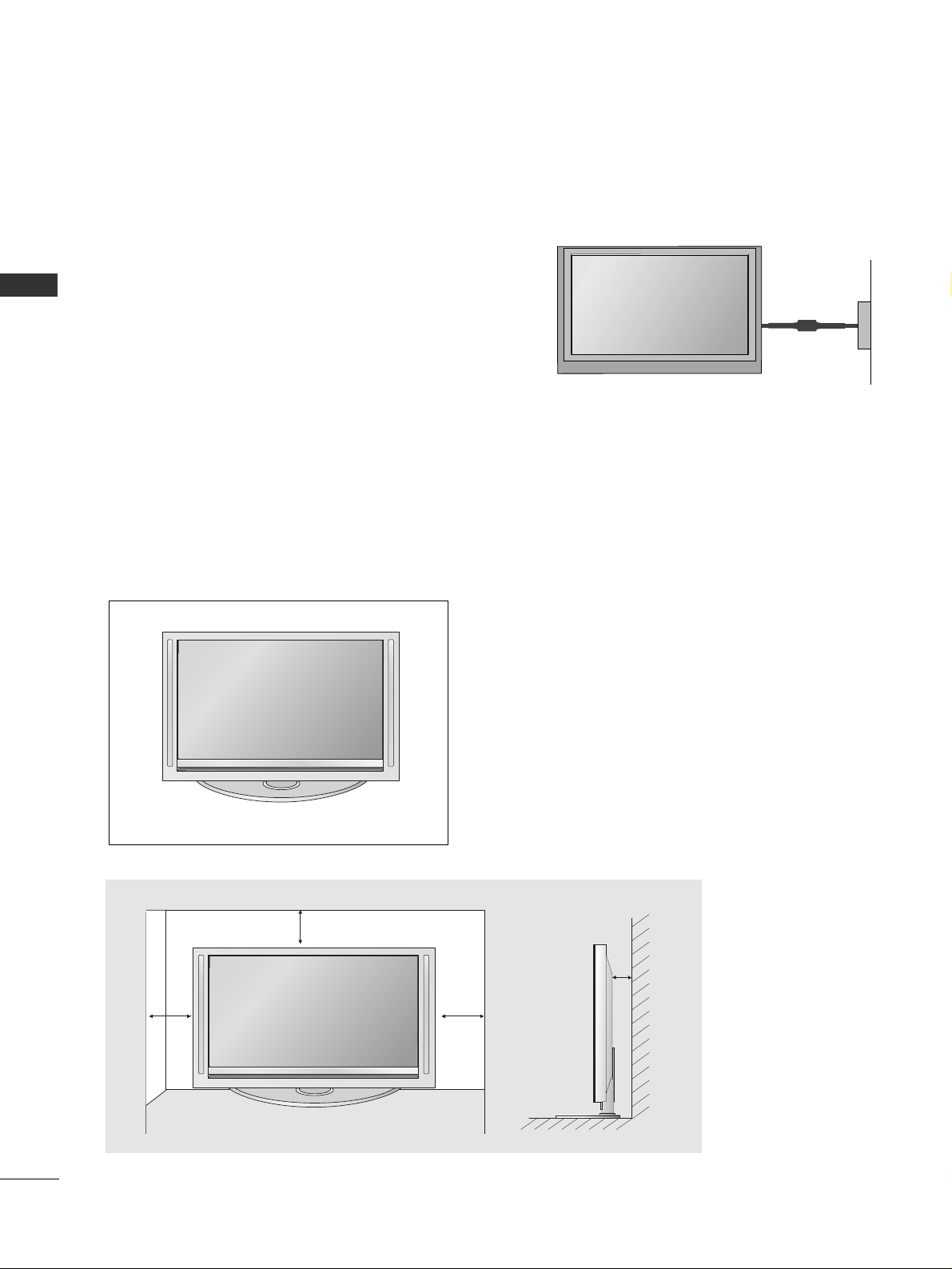
PREPARATION
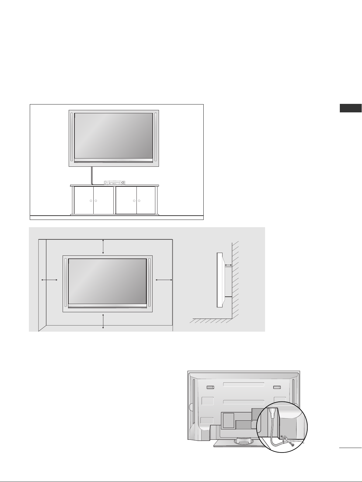
■
The TV can be installed in various ways such as on a wall, or on a desktop etc.
■
The TV is designed to be mounted horizontally.
Power Supply
Short-circuit
Breaker
GROUNDING
Ensure that you connect the earth ground wire to prevent
possible electric shock. If grounding methods are not possible, have a qualified electrician install a separate circuit
breaker.
Do not try to ground the unit by connecting it to telephone
wires, lightening rods, or gas pipes.
PREPARATION
DESKTOP PEDESTAL INSTALLATION
For proper ventilation, allow a clearance of 4” on each side and the top and 4” from the wall. Detailed
installation instructions are included in the optional Desktop Stand Installation and Setup Guide available
from your dealer.
4 inches
4 inches 4 inches
4 inches
7
PREPARATION
POWER CORD ARRANGEMENT
After connecting the power cord to the AC input
terminal, remove the bolt at the hole on the back
cover and fix the power cord at the rear side of the
TV by using the bracket for fixing the power cord.
WALL MOUNT: HORIZONTAL INSTALLATION
For proper ventilation, allow a clearance of 4" on each side and from the wall. Detailed installation instruc-tions are
available from your dealer, see the optional Tilt Wall Mounting Bracket Installation and Setup Guide.
4 inches
4 inches
4 inches
4 inches
4 inches
8
PREPARATION
AV IN 2
L/ MONO
R
AUDIO
VIDEO
S-VIDEO
AV IN 2
L/ MONO
R
AUDIO
VIDEO
S-VIDEO
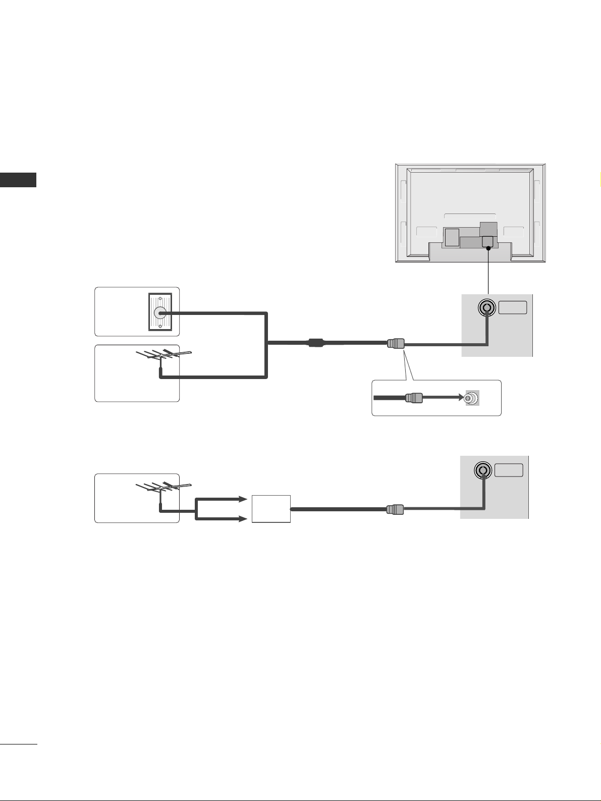
ANTENNA CONNECTION
■
For optimum picture quality, adjust antenna direction.
■
An antenna cable and converter are not supplied.
Multi-family Dwellings/Apartments
(Connect to wall antenna socket)
Single-family Dwellings /Houses
(Connect to wall jack for outdoor antenna)
Outdoor
Antenna
Wall
Antenna
Socket
RF Coaxial Wire (75 ohm)
Antenna
UHF
Signal
Amplifier
VHF
■
In poor signal areas,to get better picture quality, install a signal amplifier to the antenna as shown to the right.
■
If signal needs to be split for two TVs,use an antenna signal splitter for connection.
■
To prevent the equipment damage, never plug in any power cords until you have finished connecting all equipment.
PREPARATION
ANTENNA
IN
ANTENNA
IN
9
EXTERNAL EQUIPMENT SETUP
EXTERNAL EQUIPMENT SETUP
HDMI IN HDMI DVI IN
1
2
COMPONENT INCOMPONENT IN
AUDIO
VIDEO
HDMI IN HDMI DVI IN
HDMI/DVI IN
1
1 2
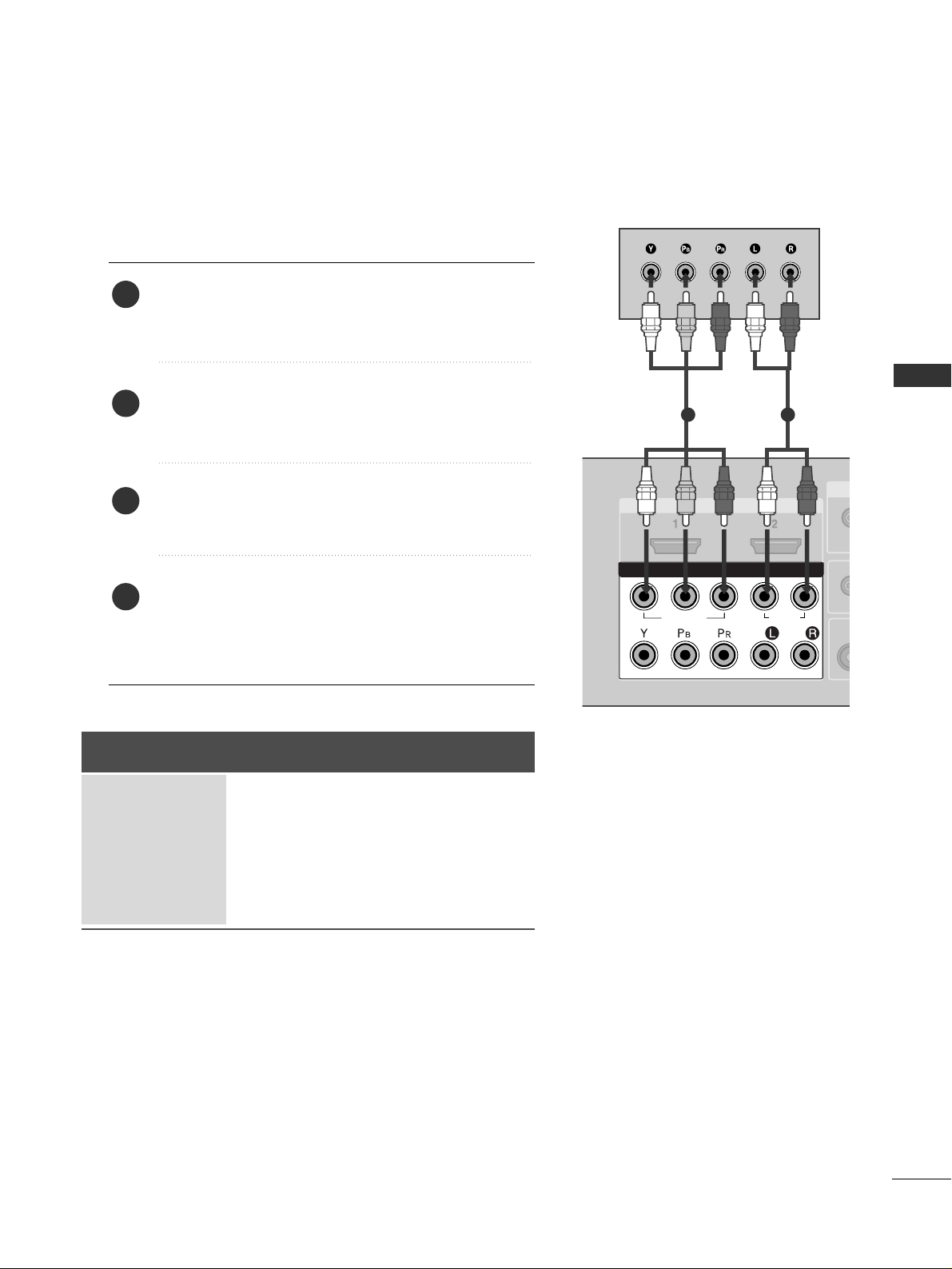
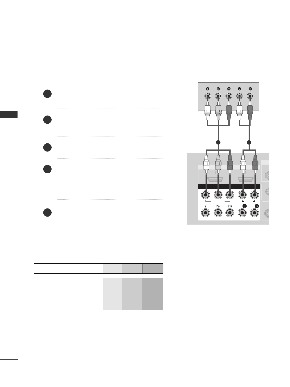
HD RECEIVER SETUP
When connecting with a component cable
Connect the video outputs (Y, PB
, PR
)
of the digital set
top box to the
CC OOMMPPOONNEENN TT IINN VV IIDD EEOO
jacks on the
set.
Connect the audio output of the digital set-top box to
the
CC OOMMPPOONN EENN TT IINN AAUUDDIIOO
jacks on the set.
Turn on the digital set-top box.
(
Refer to the owner’s manual for the digital set-top box.
)
Select
Component1 input source with using the
IINN PPUUTT
button on the remote control.
If connected to
CC OOMMPPOONN EENNTT IINN22
, select
Component2 input source.
2
3
4
1
Signal
480i/576i
480p/576p
720p
1080 i
1080p(50Hz/60Hz)
Component 1/2
Yes
Yes
Yes
Yes
Yes
HDMI1/DVI, HDMI2
No
Yes
Yes
Yes
Yes
■
To prevent the equipment damage, never plug in any power cords until you have finished connecting all equipment.
10
EXTERNAL EQUIPMENT SETUP
HDMI-DTV OUTPUT
HDMI IN HDMI DVI IN
1
2
COMPONENT IN
HDMI IN HDMI DVI IN
HDMI/DVI IN
1
HDMI IN HDMI DVI IN
HDMI IN HDMI IN HDMI/DVI IN HDMI/DVI IN
1 2
1
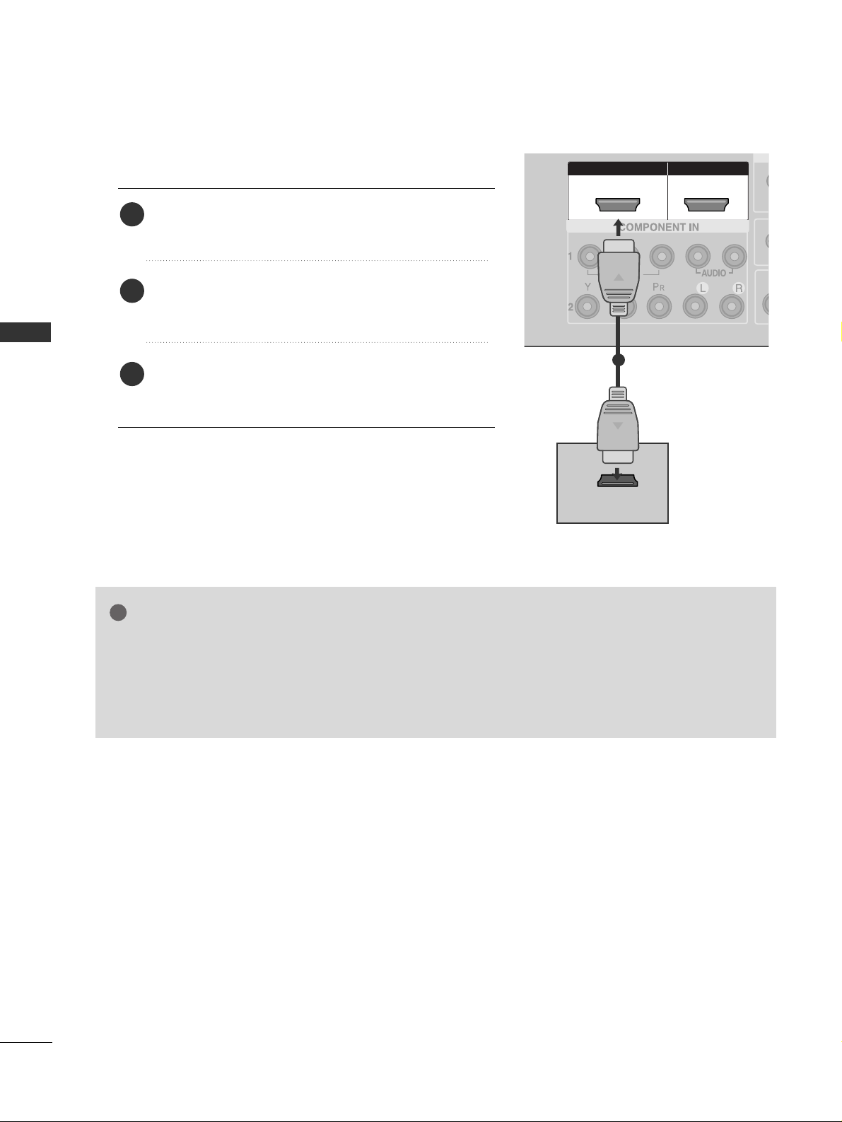
When connecting with a HDMI cable
Connect the HDMI output of the digital set-top box to
the
HHDDMMII//DDVVII IINN 11
or
HHDDMMII IINN 22
jack on the set.
Select
HDMI1/DVI or HDMI2 input source with using
the
IINN PPUUTT
button on the remote control.
Turn on the digital set-top box.
(
Refer to the owner’s manual for the digital set-top box.
)
2
3
1
GG
If the digital set-top box supports Auto HDMI function, the output resolution of the source device will
be automatically set to 1280x720p.
GG
If the digital set-top box player does not support Auto HDMI, you need to set the output resolution
appropriately.
To get the best picture quality, adjust the output resolution of the source device to 1920x1080i/1080p.
NOTE
!
EXTERNAL EQUIPMENT SETUP

11
EXTERNAL EQUIPMENT SETUP
AUDIO
(RGB/DVI)
RGB
(PC)
HDMI IN HDMI DVI IN
AUDIO
(RGB/DVI)
RGB
(PC)
RGB INRGB IN
HDMI/DVI IN HDMI/DVI IN
1
RS-232C
(CONTROL&SERVICE)
AV IN 1AV IN 1 AV OUTAV OUT
L/MONO
AUDIO OUT
1
2
Connect the DVI output of the digital set-top box to the
HHDDMMII//DDVVII IINN 11
jack on the set.
Connect the audio output of the digital set-top box to the
AAUU DDIIOO(( RRGG BB//DDVV II))
jack on the set.
Turn on the digital set-top box. (Refer to the owner’s manual for the digital set-top box.
)
Select
HDMI1/DVI input source with using the
IINN PPUUTT
button on the remote control.
2
3
4
1
When connecting with a HDMI to DVI cable
12
EXTERNAL EQUIPMENT SETUP
HDMI IN HDMI IN HDMI DVI IN HDMI DVI IN
1
2
COMPONENT INCOMPONENT IN
AUDIO
VIDEO
1 2
DVD SETUP
When connecting with a component cable
Component Input ports
To get better picture quality, connect a DVD player to the component input ports as shown below.
Component ports on the TV
YPBP
R
Video output ports
on DVD player
Y
Y
Y
Y
PB
B-Y
Cb
Pb
P
R
R-Y
Cr
Pr
Connect the video outputs (Y, PB
, PR
)
of the DVD to the
CC OOMMPPOONNEENN TT IINN VV IIDD EEOO
jacks on the set.
Connect the audio outputs of the DVD to the
CC OOMMPPOO--
NNEENNTT IINN AAUUDDIIOO
jacks on the set.
Turn on the DVD player, insert a DVD.
Select
Component
11
input source with using the
IINN PPUUTT
button on the remote control.
If connected to
CC OOMMPPOONN EENNTT IINN22
, select
Component2
input source.
Refer to the DVD player's manual for operating instructions.
2
3
4
5
1
EXTERNAL EQUIPMENT SETUP
13
EXTERNAL EQUIPMENT SETUP
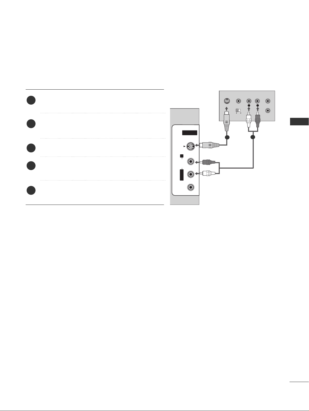
When connecting with an S-Video cable
Connect the S-VIDEO output of the DVD to the
SS--
VVIIDD EEOO
input on the set.
Connect the audio outputs of the DVD to the
AAUU DDIIOO
input jacks on the set.
Turn on the DVD player, insert a DVD.
Select
AV 2 input source with using the
IINN PPUUTT
but-
ton on the remote control.
Refer to the DVD player's manual for operating
instructions.
2
3
4
5
1
L
R
S-VIDEO
VIDEO
OUTPUT
SWITCH
ANT IN
ANT OUT
HDMI IN HDMI DVI IN
1
2
COMPONENT IN
AV IN 2AV IN 2
L/L/MONOMONO
R
AUDIOAUDIO
VIDEOVIDEO
S-VIDEOS-VIDEO
1
2
14
EXTERNAL EQUIPMENT SETUP
HDMI IN HDMI IN HDMI DVI IN HDMI DVI IN
HDMI IN HDMI IN HDMI/DVI IN HDMI/DVI IN
1 2
1
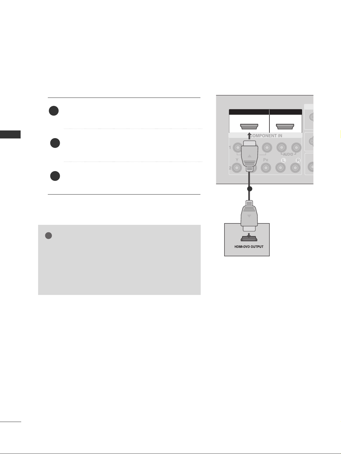
When connecting HDMI cable
Connect the HDMI output of the DVD to the
HHDDMMII//DDVVII IINN 11
or
HHDDMMII IINN 22
jack on the set.
Select
HDMI1/DVI or HDMI2 input source with
using the
IINN PPUUTT
button on the remote control.
Refer to the DVD player's manual for operating
instructions.
1
GG
If the DVD supports Auto HDMI function, the DVD output
resolution will be automatically set to 1280x720p.
GG
If the DVD player does not support Auto HDMI, you need
to set the output resolution appropriately.
To get the best picture quality, adjust the output resolution
of the DVD to 1920x1080i/1080p.
NOTE
!
2
3
EXTERNAL EQUIPMENT SETUP
15
EXTERNAL EQUIPMENT SETUP
AV IN 1AV IN 1 AV OUTAV OUT
L/MONO
AV IN 2
L/ MONO
R
AUDIO
VIDEO
S-VIDEO
ANTENNA
IN
OUTPUT
SWITCH
ANT IN
R
S-VIDEO VIDEO
ANT OUT
L
AUDIO
(RGB/DVI)
(PC)
RS-232C
(CONTROL&SERVICE)
Wall Jack
Antenna
1
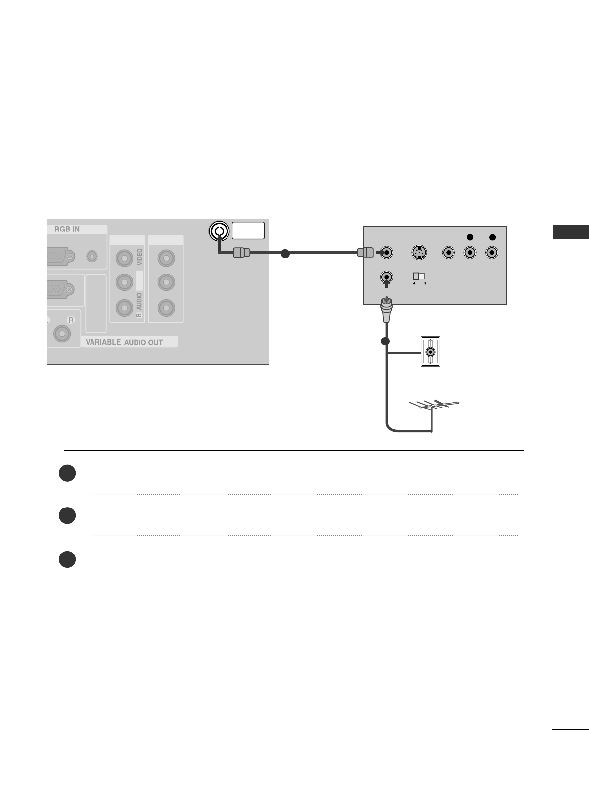
VCR SETUP
When connecting with an antenna
■
To avoid picture noise (interference), leave an adequate distance between the VCR and TV.
■
Typically a frozen still picture from a VCR. If the 4:3 picture format is used; the fixed images on the sides of
the screen may remain visible on the screen.
Connect the
AANNTT OOUU TT
socket of the VCR to the
AANNTT EENNNNAA IINN
socket on the set.
Connect the antenna cable to the
AANNTT II NN
socket of the VCR.
Press the
PPLL AAYY
button on the VCR and match the appropriate programme between the TV and VCR for
viewing.
1
2
2
3
1
16
EXTERNAL EQUIPMENT SETUP
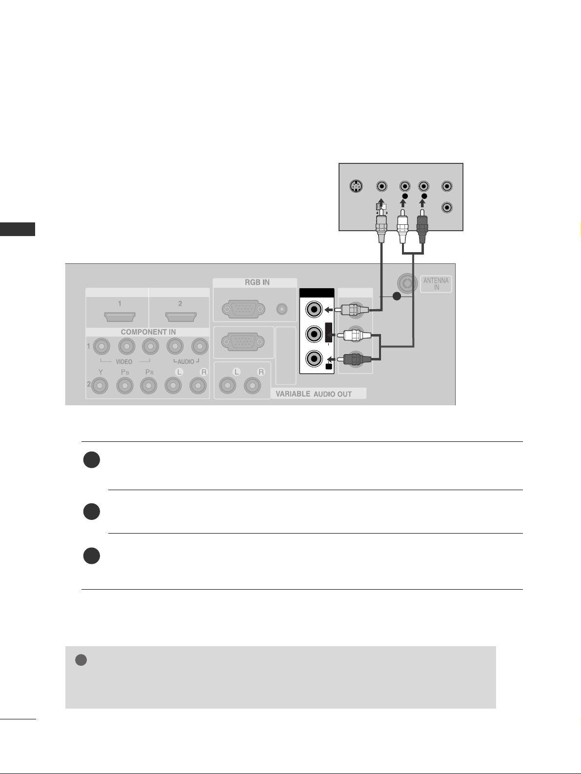
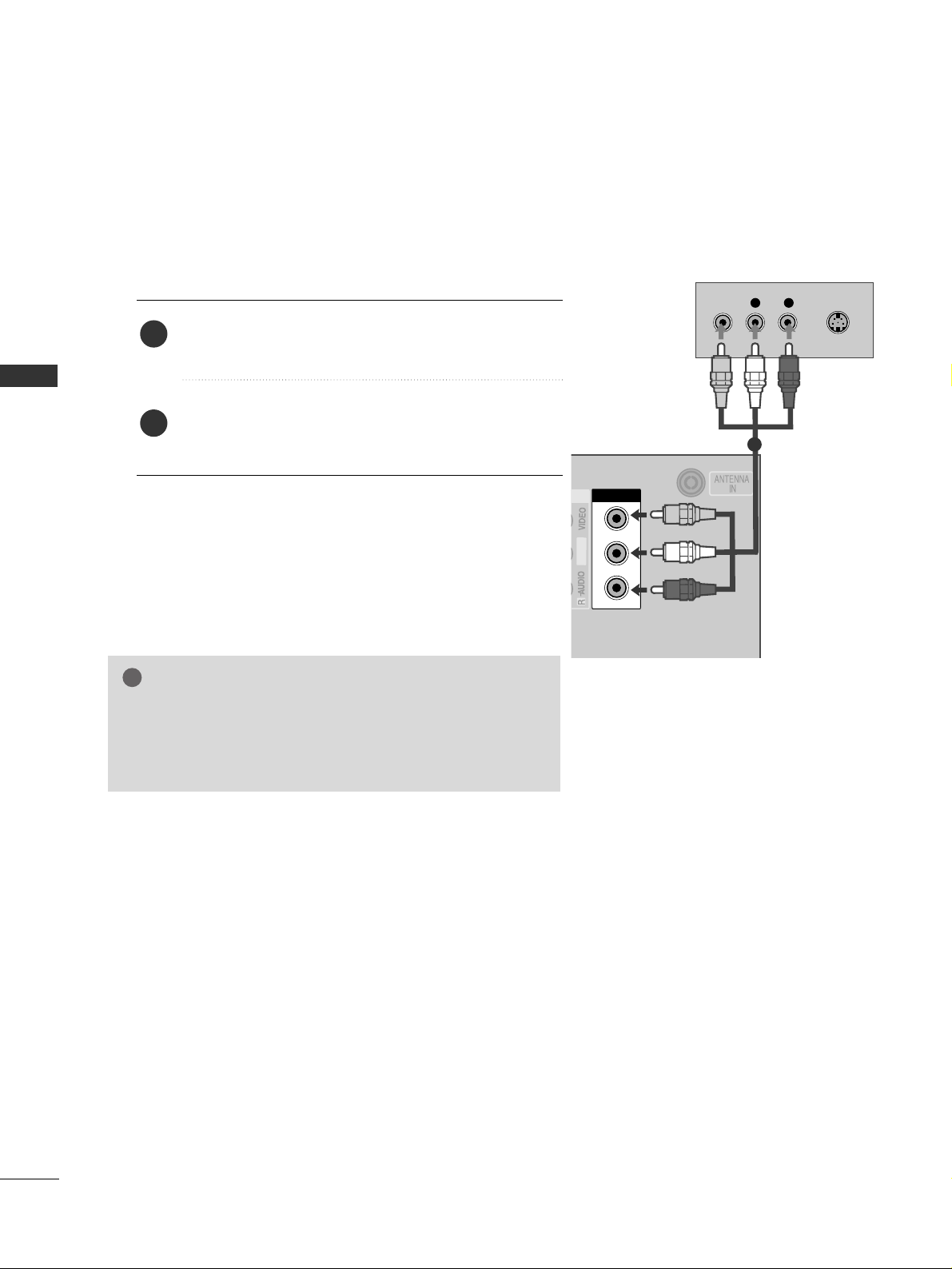
When connecting with a RCA cable
AV IN 1AV IN 1 AV OUTAV OUT
L/MONO
AV IN 2
L/ MONO
R
AUDIO
VIDEO
S-VIDEO
AV IN 1
L/L/MONOMONO
R
AUDIOAUDIO
VIDEOVIDEO
L
R
S-VIDEO
VIDEO
OUTPUT
SWITCH
ANT IN
ANT OUT
AUDIO
(RGB/DVI)
RGB
(PC)
HDMI IN HDMI DVI IN
RS-232C
(CONTROL&SERVICE)
Connect the
AAUU DDIIOO/VVIIDD EEOO
jacks between TV and VCR. Match the jack colours (Video = yellow,
Audio Left = white, and Audio Right = red)
Insert a video tape into the VCR and press PLAY on the VCR. (Refer to the VCR owner’s manual.
)
Select
AV 1 input source using the
IINN PPUUTT
button on the remote control.
If connected to
AAVV IINN22
, select
AV 2 input source.
1
2
3
GG
If you have a mono VCR, connect the audio cable from the VCR to the
AAUU DDIIOO LL// MMOONNOO
jack
of the set.
NOTE
!
1
EXTERNAL EQUIPMENT SETUP
17
EXTERNAL EQUIPMENT SETUP
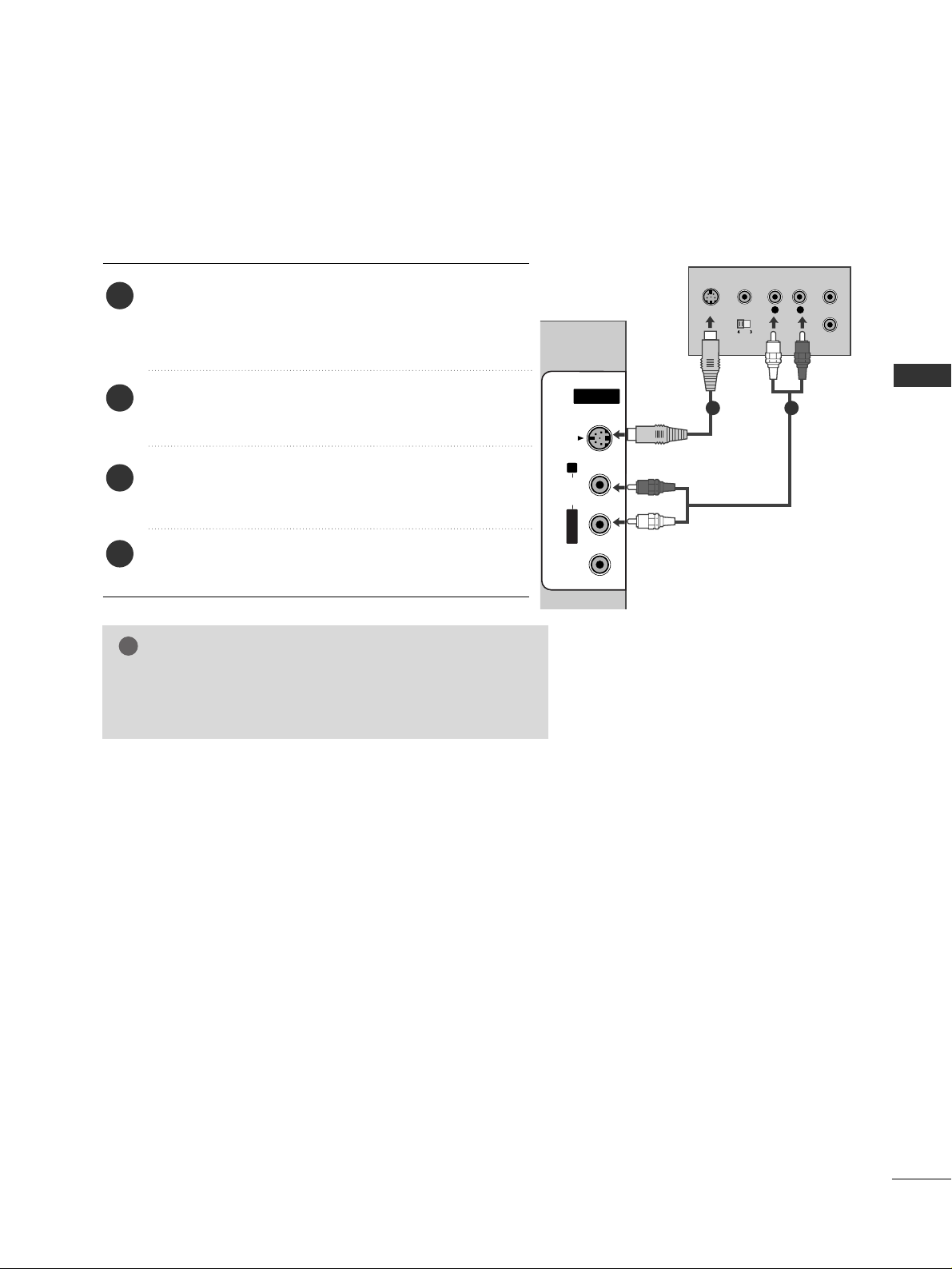
GG
If both S-VIDEO and VIDEO sockets have been connected to
the S-VHS VCR simultaneously, only the S-VIDEO can be
received.
NOTE
!
L
R
S-VIDEO
VIDEO
OUTPUT
SWITCH
ANT IN
ANT OUT
AV IN 2
L/MONOMONO
R
AUDIOAUDIO
VIDEOVIDEO
S-VIDEO
When connecting with an S-Video cable
Connect the S-VIDEO output of the VCR to the
SS--
VVIIDD EEOO
input on the set. The picture quality is
improved; compared to normal composite (RCA cable)
input.
Connect the audio outputs of the VCR to the
AAUU DDIIOO
input jacks on the set.
Insert a video tape into the VCR and press PLAY on
the VCR. (Refer to the VCR owner’s manual.)
Select
AV 2 input source with using the
IINN PPUUTT
but-
ton on the remote control.
2
3
4
1
1 2

18
EXTERNAL EQUIPMENT SETUP
AV IN 2V IN 2
L/L/MONOMONO
R
AUDIOAUDIO
VIDEOVIDEO
S-VIDEOS-VIDEO
L R
VIDEO
Camcorder
Video Game Set
1
OTHER A/V SOURCE SETUP
Connect the
AAUU DDIIOO/VVIIDD EEOO
jacks between TV and external equipment. Match the jack colours
.
(
Video = yellow, Audio Left = white, and Audio Right = red
)
Select AV 2 input source with using the
IINN PPUUTT
button on the remote control.
If connected to
AAVV IINN11
, select
AV 1 input source.
Operate the corresponding external equipment.
Refer to external equipment operating guide.
1
2
3
EXTERNAL EQUIPMENT SETUP
19
EXTERNAL EQUIPMENT SETUP
AUDIO
(RGB/DVI)
RGB
(PC)
AUDIO
(RGB/DVI)
RGB
(PC)
RGB INRGB IN
HDMI IN
HDMI IN HDMI/DVI IN
12
R
S
-2
3
2
C
IN
(C
O
N
T
R
O
L
&
S
E
R
V
IC
E
)
AV IN 1AV IN 1 AV OUTAV OUT
L/M
O
NO
RGB OUTPUT
AUDIO
HDMI IN HDMI DVI IN
1
2
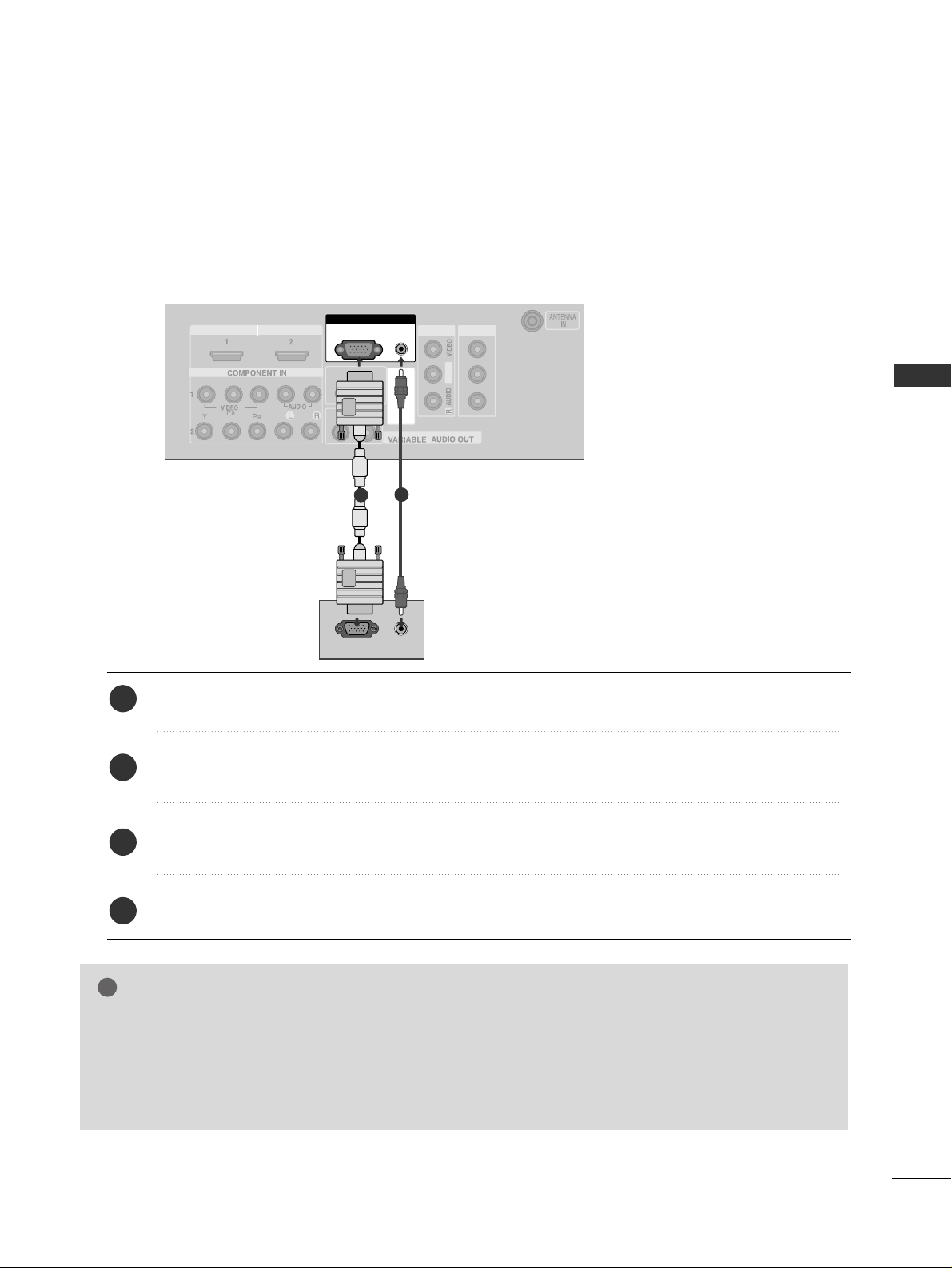
PC SETUP
This TV provides Plug and Play capability, meaning that the PC adjusts automatically to the TV's settings.
When connecting with a D-sub 15 pin cable
Connect the RGB output of the PC to the
RRGGBB ((PPCC
))
jack on the set.
Connect the PC audio output to the
AAUU DDIIOO(( RRGG BB//DDVV II))
jack on the set.
Turn on the PC and the set.
Select
RGB PC input source with using the
IINN PPUUTT
button on the remote control.
2
3
4
1
GG
Check the image on your TV. There may be noise associated with the resolution, vertical pattern, contrast or
brightness in PC mode. if noise is present, change the PC output to another resolution, change the refresh rate to
another rate or adjust the brightness and contrast on the VIDEO menu until the picture is clear. If the refresh rate
of the PC graphic card can not be changed, change the PC graphic card or consult the manufacturer of the PC
graphic card.
NOTE
!

20
EXTERNAL EQUIPMENT SETUP
EXTERNAL EQUIPMENT SETUP
DVI-PC OUTPUT
AUDIO
RGB IN
HDMI IN
HDMI DVI IN
HDMI IN HDMI/DVI IN
12
HDMI IN HDMI DVI IN
AUDIO
(RGB/DVI)
RGB
(PC)
HDMI IN HDMI DVI IN
AUDIO
(RGB/DVI)
RGB
(PC)
RGB INRGB IN
HDMI/DVI IN HDMI/DVI IN
1
RS-232C
(CONTROL&SERVICE)
AV IN 1AV IN 1 AV OUTAV OUT
L
/M
O
N
O
AUDIO OUT
1
2
Connect the DVI output of the PC to the
HHDDMMII//DDVVII IINN 11
jack on the set.
Connect the PC audio output to the
AAUU DDIIOO(( RRGG BB//DDVV II))
jack on the set.
Turn on the PC and the set.
Select
HDMI1/DVI input source with using the
IINN PPUUTT
button on the remote control.
2
3
4
1
When connecting with a HDMI to DVI cable
GG
HDMI2 source does not support DVI source.
GG
If the PC has a DVI output and no HDMI output, a separated audio connection is necessary.
GG
If the PC does not support Auto DVI, you need to set the output resolution appropriately.
NOTE
!

21
EXTERNAL EQUIPMENT SETUP
Resolution
720x400
640x480
800x600
1024x768
1280x768
1280x960
(HDMI[PC]only)
1360x768
1366x768
1280x1024
1400x1050
(RGB[PC]only)
1600x1200
1920x1080
1920 x 120 0
Supported Display Resolution (RGB[PC]/HDMI[PC]mode)
Horizontal Vertical
Frequency(kHz) Frequency(Hz)
31.469 70.08
31.469 59.94
37.879 60.31
48.363 60.00
47.776 59.870
59.699 59.939
47.720 59.799
47.13 59.65
63.981 60.02
65.317 59.978
75.0 60.0
66.587 59.934
74.038 59.950
NOTE
!
GG
To get the best picture quality, adjust the PC graphics card to 1920x1080, 60Hz.
GG
Depending on the graphics card, DOS mode may not work if a HDMI to DVI Cable is in use.
GG
When Source Devices connected with HDMI Input, output TV SET Resolution (480p, 720p, 1080i) and
TV SET Display fit EIA/CEA-861-B Specification to Screen. If not, refer to the Manual of HDMI Source
Devices or contact your service center.
GG
If the HDMI Source Device is not connected to the Cable or if there is a poor cable connection, "No signal" is displayed in the HDMI Input. In this case, that Video Resolution is not supported.
GG
Avoid keeping a fixed image on the screen for a long period of time. The fixed image may become permanently imprinted on the screen.
GG
The synchronization input form for Horizontal and Vertical frequencies is separate.
GG
When you use too long RGB-PC cable, there might be a noise on the screen. We recommend using under
5m of the cable. It provides the best picture quality.

22
EXTERNAL EQUIPMENT SETUP
EXTERNAL EQUIPMENT SETUP
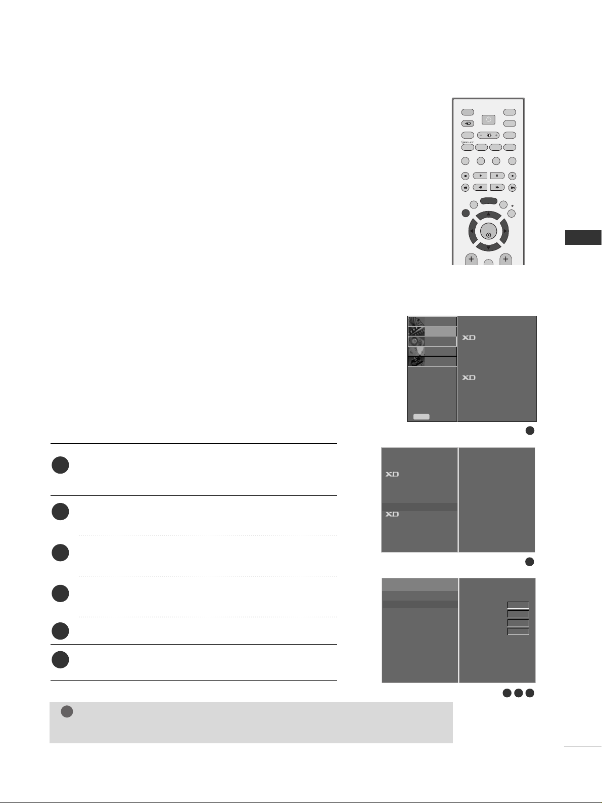
Press the
MMEENNUU
button and then use
DD
//
EE
button to
select the
PICTURE menu.
Press the
GG
button and then use
DD
//
EE
button to select
Screen.
Press the
GG
button and then use
DD
//
EE
button to select
Auto Config..
Press the
GG
button to start Auto Config..
• When
AAuuttoo cc oonnffiigg..
has finished, OK will be shown on
screen.
• If the position of the image is still not correct, try Auto
adjustment again.
• If picture needs to be adjusted more after Auto adjustment in RGB (PC), you can adjust the
Manual Config..
Press the
EEXXIITT
button to return to TV viewing.
Automatically adjusts picture position and minimizes image
shaking.After adjustment, if the image is still not correct, your
set is functioning properly but needs further adjustment.
AAuuttoo cc oonnff iigg uu rree
This function is for the automatic adjustment of the screen
position, clock, and phase. The displayed image will unstable for
a few seconds while the auto configuration is in progress.
1
2
3
4
5
Screen Setup for PC mode
Auto Configure (RGB [PC] mode only)
1
3 4
2
SETUP
O
PICTURE G
Prev.
Menu
AUDIO
O
TIME
O
OPTION
O
To Set
Auto Config. G
Manual Config.
XGA Mode
Reset
To Set
Picture Mode
Colour Temperature
Advanced
Aspect Ratio
Picture Reset
Screen
Demo
Picture Mode
Colour Temperature
Advanced
Aspect Ratio
Picture Reset
Screen
G
Demo
Screen
OK
INPUT MODE
TVTV
DVD
RATIO
EXIT
PIP
SLEEP
LIST
Q.VIEW
I/II
MENU
VCR
PIP PR- PIP PR+
PIP INPUT
POWER
SIMPLINK
INPUT
SWAP
BRIGHT
23
EXTERNAL EQUIPMENT SETUP
If the picture isn’t clear after auto adjustment and especially if
characters are still trembling, adjust the picture phase manually.
It’s not available to use this function in 1:1 Pixel mode.
To correct the screen size, adjust
CC lloo cckk
.
This function works in the following mode : RGB[PC], COMPONENT (480i/480p/576i/576p/720p/1080i/1080p),
HDMI (480p/576p/720p/1080i/1080p).
It’s not available to use Phase, Clock function in COMPONENT
(480i/480p/576i/576p/720p/1080i/1080p),
HDMI (480p/576p/720p/1080i/1080p).
CC lloo cckk
This function is to minimize any vertical bars or stripes
visible on the screen background. And the horizontal
screen size will also change.
PPhhaassee
This function allows you to remove any horizontal noise
and clear or sharpen the image of characters.
Press the
MMEENNUU
button and then use
DD
//
EE
button to
select the
PICTURE menu.
Press the
GG
button and then use
DD
//
EE
button to select
Screen.
Press the
GG
button and then use
DD
//
EE
button to select
Manual Config..
Press the
GG
button and then use
DD
//
EE
button to select
Phase, Clock, H-Position or V-Position.
Press the
FF
//
GG
button to make appropriate adjustments.
Press the
EEXXIITT
button to return to TV viewing.
1
2
3
4
5
6
Adjustment for screen Phase, Clock, Position
1
3 4 5
2
SETUP
O
PICTURE G
Prev.
Menu
AUDIO
O
TIME
O
OPTION
O
To Set
Auto Config.
Manual Config.
G
XGA Mode
Reset
Phase
Clock
H-Position
V-Position
0
0
0
0
Picture Mode
Colour Temperature
Advanced
Aspect Ratio
Picture Reset
Screen
Demo
Picture Mode
Colour Temperature
Advanced
Aspect Ratio
Picture Reset
Screen
G
Demo
Screen
GG
In HDMI or COMPONENT mode, 1080p works at 50Hz/60Hz only.
NOTE
!
OK
INPUT MODE
TVTV
DVD
RATIO
EXIT
PIP
SLEEP
LIST
Q.VIEW
I/II
MENU
VCR
PIP PR- PIP PR+
PIP INPUT
POWER
SIMPLINK
INPUT
SWAP
BRIGHT

24
EXTERNAL EQUIPMENT SETUP
EXTERNAL EQUIPMENT SETUP
To see a normal picture, match the resolution of RGB mode and
selection of XGA/UXGA mode.
This function works in the following mode: RGB[PC] mode.
Press the
MMEENNUU
button and then use
DD
//
EE
button to
select the
PICTURE menu.
Press the
GG
button and then use
DD
//
EE
button to select
Screen.
Press the
GG
button and then use
DD
//
EE
button to select
XGA Mode (or UXGA Mode)
.
Press the
GG
button and then use
DD
//
EE
button to select
the desired XGA/UXGA resolution.
Press the
EEXXIITT
button to return to TV viewing.
Selecting Wide XGA/UXGA mode
1
2
3
4
5
1
3 4
2
SETUP
O
PICTURE G
Prev.
Menu
AUDIO
O
TIME
O
OPTION
O
To Set
Auto Config.
Manual Config.
UXGA Mode
G
Reset
1600 X 1200
1920 X 1200
Picture Mode
Colour Temperature
Advanced
Aspect Ratio
Picture Reset
Screen
Demo
Picture Mode
Colour Temperature
Advanced
Aspect Ratio
Picture Reset
Screen
G
Demo
Screen
OK
INPUT MODE
TVTV
DVD
RATIO
EXIT
PIP
SLEEP
LIST
Q.VIEW
I/II
MENU
VCR
PIP PR- PIP PR+
PIP INPUT
POWER
SIMPLINK
INPUT
SWAP
BRIGHT

25
EXTERNAL EQUIPMENT SETUP
This function operates in current mode.
To initialize the adjusted value
Press the MENU button and then use
DD
//
EE
button to
select the
PICTURE menu.
Press the
GG
button and then use
DD
//
EE
button to select
Screen.
Press the
GG
button and then use
DD
//
EE
button to select
Reset.
Press the
GG
button.
• You can initialize Position.
Press the
EEXXIITT
button to return to TV viewing.
1
2
3
4
Initializing
(Reset to original factory settings)
1
3 4
2
SETUP
O
PICTURE G
Prev.
Menu
AUDIO
O
TIME
O
OPTION
O
To Set
Auto Config.
Manual Config.
XGA Mode
Reset
G
To Set
Picture Mode
Colour Temperature
Advanced
Aspect Ratio
Picture Reset
Screen
Demo
Picture Mode
Colour Temperature
Advanced
Aspect Ratio
Picture Reset
Screen
G
Demo
5
Screen
OK
INPUT MODE
TVTV
DVD
RATIO
EXIT
PIP
SLEEP
LIST
Q.VIEW
I/II
MENU
VCR
PIP PR- PIP PR+
PIP INPUT
POWER
SIMPLINK
INPUT
SWAP
BRIGHT
26
EXTERNAL EQUIPMENT SETUP
AV OUTPUT SETUP
The TV has a special signal output capability which allows you to hook up the second TV or monitor.
L R
S-VIDEOVIDEO
L/MONO
AV OUT
Connect the second TV or monitor to the TV’s
AAVV OOUUTT
jacks.
See the Operating Manual of the second TV or monitor
for further details regarding that device’s input settings.
GG
Component, RGB, HDMI input sources cannot be used for
AV out.
GG
We recommend to use the AV OUT jacks for VCR recording.
NOTE
!
2
1
1

27
EXTERNAL EQUIPMENT SETUP
EXTERNAL STEREO SETUP
HDMI IN HDMI DVI IN
VARIABLE ARIABLE AUDIO OAUDIO OUT
(CON
AV OUT
GG
When connecting with external audio equipments, such as
amplifiers or speakers, please turn the TV speakers off.
(
GG
pp..6633
)
NOTE
!
Use to connected either an external amplifier, or add a subwoofer to your surround sound system.
Connect the input jack of the stereo amplifier to the
VVAARRIIAABBLL EE AAUU DDIIOO OOUU TT
jacks on the set.
Set up your speakers through your analog stereo
amplifier, according to the instructions provided with
the amplifier.
2
1
11
 Loading...