

LG 60PT100C-WA Users guide

OWNER’S MANUAL
MultiVision
Please read this manual carefully before operating
the set and retain it for future reference.
60PT100C
60PT100N
ENGLISH
ENG
SAFETY INSTRUCTIONS
2
WARNING / CAUTION
Please read these safety precautions carefully before using the product.
y
In this manual, the illustration may be somewhat different from your product because it is
y
just example to help the instruction.
Read these instructions.
Keep these instructions.
Heed all warnings.
Follow all instructions.
TO REDUCE THE RISK OF ELECTRIC
SHOCK DO NOT REMOVE COVER (OR
BACK). NO USER SERVICEABLE PARTS
INSIDE. REFER TO QUALIFIED SERVICE
PERSONNEL.
The lightning flash with arrowhead
symbol, within an equilateral triangle,
is intended to alert the user to the
presence of uninsulated “dangerous voltage”
within the product’s enclosure that may be of
sufficient magnitude to constitute a risk of
electric shock to persons.
The exclamation point within an
equilateral triangle is intended to
alert the user to the presence of
important operating and maintenance (servicing) instructions in the literature accompanying the appliance.
WARNING/CAUTION
TO REDUCE THE RISK OF FIRE AND
ELECTRIC SHOCK. DO NOT EXPOSE THIS
PRODUCT TO RAIN OR MOISTURE.
Do not use this apparatus near water.
y
Clean only with dry cloth.
y
Do not block any ventilation openings. In-
y
stall in accordance with the manufacturer’s
instructions.
Do not install near any heat sources such as
y
radiators, heat registers, stoves, or other apparatus (in cluding amplifiers) that produce
heat.
Do not defeat the safety purpose of the
y
polarized or grounding-type plug. A polarized plug has two blades with one wider
than the other. A grounding type plug has
two blades and a third grounding prong, The
wide blade or the third prong are provided
for your safety. If the provided plug does not
fit into your outlet, consult an electrician for
replacement of the obsolete outlet.
Protect the power cord from being walked
y
on or pinched particularly at plugs, convenience receptacles, and the point where they
exit from the apparatus.
SAFETY INSTRUCTIONS
Unplug this apparatus during lighting storms
y
or when unused for long periods of time.
Refer all servicing to qualified service per-
y
sonnel. Servicing is required when the apparatus has been damaged in any way, such
as power-supply cord or plug is damaged,
liquid has been spilled or objects have fallen
into the apparatus, the apparatus has been
exposed to rain or moisture, does not operate normally, or has been dropped.
3
ENGENGLISH
Only use attachments/accessories specified
y
by the manufacturer.
Use only with a cart, stand, tripod, bracket,
y
or table specified by the manufacturer, or
sold with the apparatus. When a cart is
used, use caution when moving the cart/apparatus combination to avoid injury from tipover.
Never touch this apparatus or antenna dur-
y
ing a thunder or lighting storm.
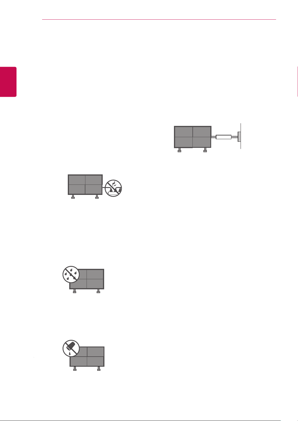
When mounting a monitor on the wall, make
y
sure not to install the monitor by the hanging
power and signal cables on the back of the
monitor.
Do not allow an impact shock or any objects
y
to fall into the product, and do not drop onto
the screen with something.
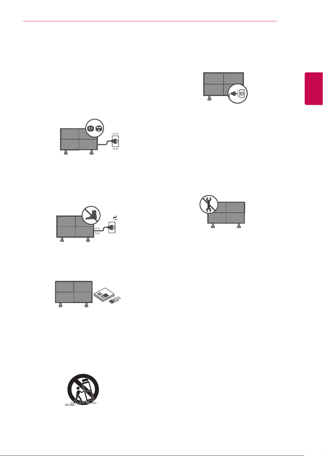
CAUTION concerning the Power Cord:
y
It is recommend that appliances be placed
upon a dedicated circuit; that is, a single
outlet circuit which powers only that appliance and has no additional outlets or branch
circuits. Check the specification page of this
owner's manual to be certain.
Do not connect too many appliances to the
same AC power outlet as this could result in
fire or electric shock.
Do not overload wall outlets. Overloaded
wall outlets, loose or damaged wall outlets,
extension cords, frayed power cords, or
damaged or cracked wire insulation are dan-
SAFETY INSTRUCTIONS
4
ENGLISH
ENG
gerous . Any of these conditions could result
in electric shock or fire. Periodically examine
the cord of your appliance, and if its appearance indicates damage or deterioration,
unplug it, discontinue use of the appliance,
and have the cord replaced with an exact
replacement part by an authorized servicer.
Protect the power cord from physical or
mechanical abuse, such as being twisted,
kinked, pinched, closed in a door, or walked
upon. Pay particular attention to plugs, wall
outlets, and the point where the cord exits
the appliance.
Do not make the monitor with the power cord
plugged in. Do not use a damaged or loose
power cord. Be sure do grasp the plug when
unplugging the power cord. Do not pull on
the power cord to unplug the monitor.
WARNING - To reduce the risk of fire or
y
electrical shock, do not expose this product
to rain, moisture or other liquids. Do not
touch the monitor with wet hands. Do not
install this product near flammable objects
such as gasoline or candles or expose the
monitor to direct air conditioning.
GROUNDING
y
Ensure that you connect the earth ground
wire to prevent possible electric shock (i.e.
a monitor with a three-prong grounded AC
plug must be connected to a three-prong
grounded AC outlet). If grounding methods
are not possible, have a qualified electrician
install a separate circuit breaker.
Do not try to ground the unit by connecting
it to telephone wires, lightening rods, or gas
pipes.
Power
Supply
Short-circuit
Breaker
DISCONNECTING DEVICE FROM MAIN
y
Power
The power outlet must remain readily accessed in the event the device needs to be
unplugged.
As long as this unit is connected to the AC
y
wall outlet, it is not disconnected from the
AC power source even if the unit is turned
off.
Do not expose to dripping or splashing and
y
do not place objects filled with liquids, such
as vases, cups, etc. on or over the apparatus (e.g. on shelves above the unit).
Do not attempt to modify this product in any
y
way without written authorization from the
manufacturer. Unauthorized modification
could void the user’s authority to operate
this product.
Cleaning
y
When cleaning, unplug the power cord and
scrub gently with a soft cloth to prevent
scratching. Do not spray water or other liquids directly on the monitor as electric shock
may occur. Do not clean with chemicals
such as alcohol, thinners or benzene.
Moving
y
Make sure the product is turned off, unplugged and all cables have been removed.
It may take 2 or more people to carry larger
monitors. Do not press against or put stress
on the front panel of the monitor.
SAFETY INSTRUCTIONS
5
Ventilation
y
Install your monitor where there is proper
ventilation. Do not install in a confined space
such as a bookcase. Do not cover the product with cloth or other materials (e.g.) plastic
while plugged in. Do not install in excessively dusty places.
Take care not to touch the ventilation open-
y
ings. When watching the monitor for a long
period, the ventilation openings may become hot.
If you smell smoke or other odors coming
y
from the monitor or hear strange sounds,
unplug the power cord contact an authorized
service center.
When touching the monitor, use the pen
y
provided. Do not use other sharp or pointed
objects, such as your fingernail, a pen or a
pencil etc.
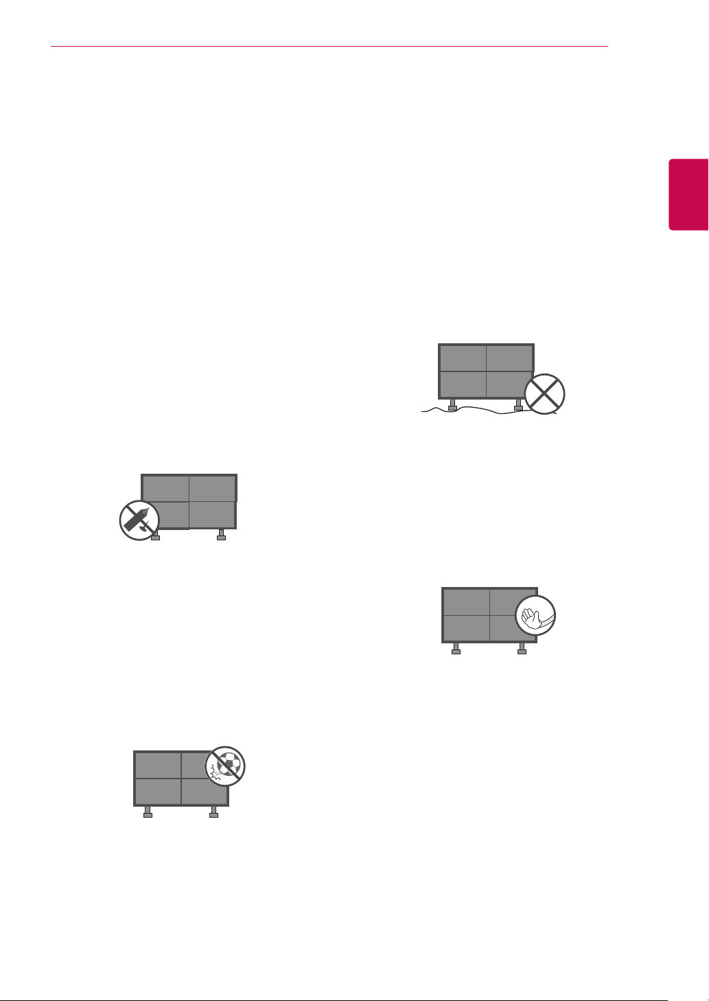
The product should be installed where its
y
weight can be supported.
If the surface of the area where the product
is installed is weak, the product may fall
causing personal injury.
Do not hang on the product or apply shock
y
to the product.
The product may fall causing personal injury.
Install the product on a flat floor.
y
If not (e.g., stairway and slope), the product
may lose its balance and fall causing personal injury or damage to product.
Disconnect the plug from the outlet before
y
installation.
Otherwise, it may cause an electric shock or
fire.
ENGENGLISH
Keep the product away from direct sun-
y
light.
Do not allow a impact shock or any objects
y
to fall into the product, and do not drop onto
the screen with something.
You may be injured or the product can be
damaged.
A protection device is required for the set
where shocks from the outside may occur.
Wear working gloves when installing the
y
product.
Otherwise, it may cause personal injury.
The edges of the product are sharp. Be
careful not to be injured by the edges during
or after installation.

TABLE OF CONTENTS
6
TABLE OF CONTENTS
ENGLISH
ENG
2 WARNING / CAUTION
7 ASSEMBLING AND PREPAR-
ING
7 Unpacking
8 - Additional accessories
9 Separate purchase
10 Back panel information
11 Transportation method for panel protec-
tion
12 Storage method for panel protection
12 - Correct method
12 - Incorrect method
13 Panel array
15 Installation method for panel protection
15 - Guide pin
16 - Guide Fixer
17 Protection cushion attachment
17 Transportation method for panel protec-
tion
18 Set mount screw
18 Cautions on installation
18 - Stand type
18 - Wall-mount type
19 Video and Control Connector
20 Brightness Adjustment Connector
21 Dip switch setting
22 IC Receiver
24 Using ferrite core
25 MAKING CONNECTIONS
25 RGB input
25 HDMI input
26 HDMI to DVI input
26 DVI input
27 Component input
27 - Component input ports
28 REMOTE CONTROL
31 WATCHING MULTIVISION
31 - Using the input list
32 CUSTOMIZING MONITOR SET-
TINGS
32 The SETUP Menu
33 - PICTURE Settings
37 - AUDIO Settings
38 - TIME Settings
39 - OPTION Settings
41 TROUBLESHOOTING
43 SPECIFICATIONS
44 MULTI-OUTLET POWER STRIP
SPECIFICATIONS
46 IR CODES
47 EXTERNAL CONTROL DEVICE
SETUP
47 RS-232C Setup
47 Type of connector;
D-Sub 9-Pin Male
48 RS-232C Configurations
49 Communication Parameters
49 Command reference list
50 Transmission / Receiving Protocol
57 OPEN SOURCE LICENSE
58 - GNU GENERAL PUBLIC LICENSE
62 - GNU Lesser General Public License
68 - Mozilla Public License 1.1 (MPL 1.1)
30 INITIALIZING SETUP
ASSEMBLING AND PREPARING
ASSEMBLING AND PREPARING
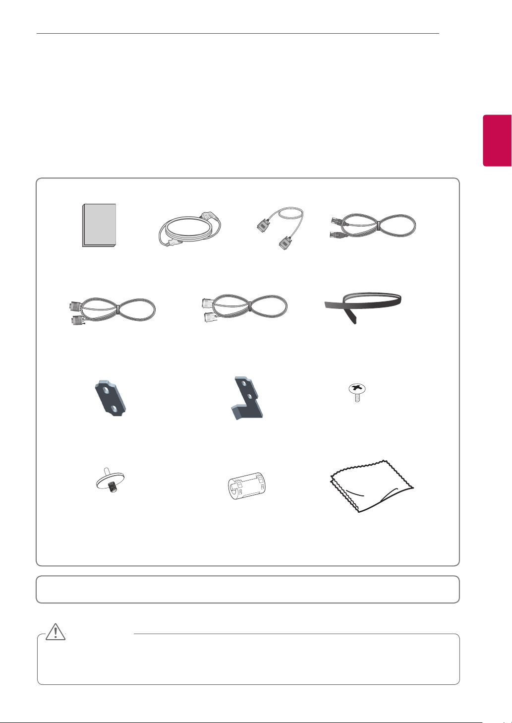
Unpacking
Check your product box for the following items. If there are any missing accessories, contact the local
dealer where you purchased your product.
The illustrations in this manual may differ from the actual product and item.
7
ENGENGLISH
Regulatory
Safety Instruction
Book
D-Sub Cable
Guide Fixer
Guide pin
Power Cord RS-232C Cable LAN Cable
DVI-D Cable
x 1
Guide Fixer
x 4
x 2
x 6
x 6
Cushion
x 6
M4 x 8
Screw for assembly
Polishing clothFerrite core
This is a class A product. In a domestic environment this product may cause radio interference, in
which case the user may be required to take adequate measures.
CAUTION
Do not use any pirated items to ensure the safety and product life span.
y
Any damages or injuries by using pirated items are not covered by the manufacturer's warranty.
y
ENGLISH
ENG
ASSEMBLING AND PREPARING
8
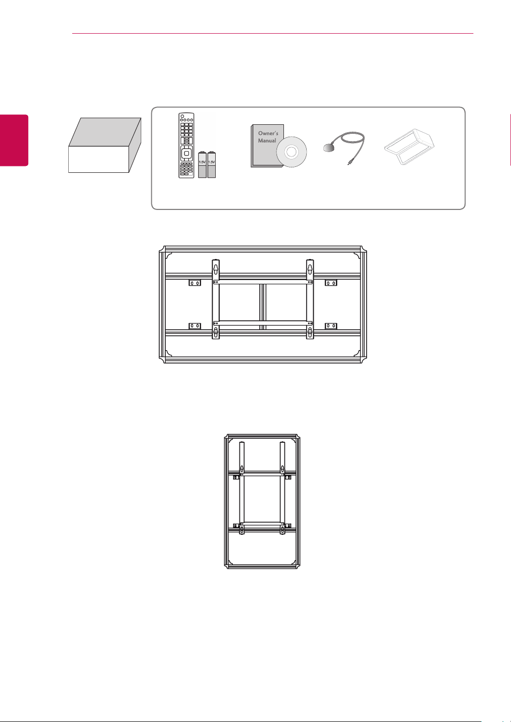
Additional accessories
x 4
Accessory box
(AA-VX200X)
Owner’s ManualRemote Control and
batteries(AAA)
MultiVision Mounting Bracket – Landscape
IR Receiver
Protection cushion
MultiVision Mounting Bracket – Portrait
A landscape or portrait-type rack is provided depending on the monitor purchased.
y
Only one set of accessories is provided, regardless of the number of monitors purchased.
y
ASSEMBLING AND PREPARING
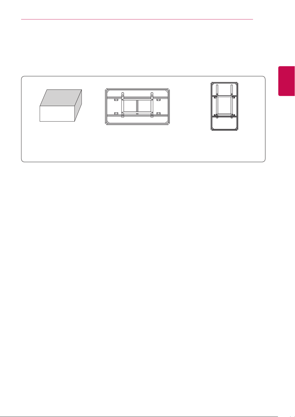
Separate purchase
Separate purchase items can be changed or modified for quality improvement without any notification.
Contact your dealer for buying these items.
9
ENGENGLISH
Accessory box
(AA-VX200X)
Optional accessories differ depending on the monitor's use or installation method.
y
To learn about optional accessories available for the monitor you purchased, please contact the local
y
retailer.
MultiVision Mounting Bracket
- landscape
(AB-VL200X)
MultiVision Mounting Bracket
– Portrait
(AB-VP200X)
ENGLISH
ENG
ASSEMBLING AND PREPARING
10
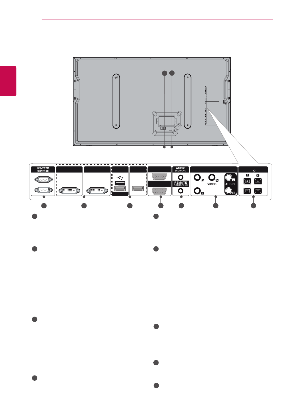
Back panel information
Image shown may differ from your monitor.
y
1
2
DVI-D OUT DVI-D IN
3
1
POWER CORD SOCKET
(SERVICE ONLY)
HDMI 2
This set operates on an AC power. The voltage is indicated on the Specifications page.
Never attempt to operate the set on DC
power.
2
CONTROL (TX, RX)
Connector to compensate the luminance difference.
Connect using LAN Cable inside the
Accessory box.
Connect LAN Cable to TX, and connect to RX
connector of other sets.
HDMI1/DVI
5
RGB OUT
RGB IN
6
5
7
USB Input (For service)
Used for software updates.
HDMI/DVI
Connect an HDMI/DVI signal to HDMI/DVI.
6
RGB OUTPUT
You can watch the RGB signal on another set,
connect RGB OUTPUT to another set’s PC
input port.
RGB INPUT
Connect the set output connector from a PC
to the appropriate input port.
USB
(This LAN port is a control port which does not
connect to the internet. It is for APL communication when multiple sets are connected in
Multi Vision mode.)
3
RS-232C INPUT(CONTROL&SERVICE)
PORT OUT
For control the another set, connect a
RS-232C Cable from RS-232C out port to
another set’s RS-232C input port.
7
AUDIO (RGB/DVI)
1/8" headphone jack for analog PC audio
input
REMOTE CONTROL IN
IN For a wired IR Receiver.
8
Connect to the RS-232C port on a PC.
COMPONENT INPUT
Connect a component video/audio device to
4
DVI OUT, IN
DVI (VIDEO) signal to DVI port with DVI
cable.
these jacks.
9
Speaker Ports
Connect to optional external speaker(s).
COMPONENT IN
8
SPEAKER
(8)
94
Transportation method for panel protection
When moving or lifting the monitor, read the
following to prevent the monitor from being
scratched or damaged and for safe transportation
regardless of its type and size.
CAUTION
Avoid touching the screen at all times, as this
y
may result in damage on the screen.
Use the handles of the monitor only to move.
y
It is recommended to move the monitor in
y
the box or packing material that the monitor
originally came in.
Before moving or lifting the monitor, disconnect
y
the power cord and all cables.
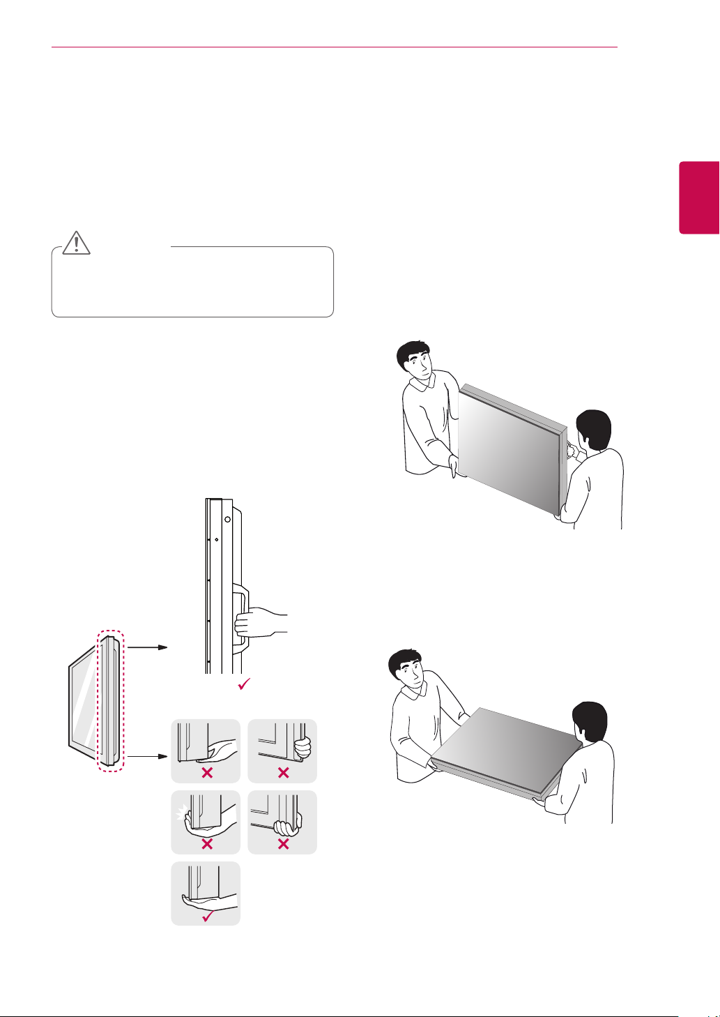
Hold firmly the handles and the bottom frame.
y
ASSEMBLING AND PREPARING
When transporting the monitor, do not expose
y
the monitor to jolts or excessive vibration.
When transporting the monitor, keep the
y
monitor upright, never turn the monitor on its
side or tilt towards the left or right.
When transporting the monitor by hand,
y
hold the monitor as shown in the following
illustration.
When the product is carried upright, two per-
y
sons should hold each handle on the top and
the bottom corner, and when it is being put
down, put down carefully for the panel not to
be touched.
11
ENGENGLISH
When the product is carried laid down, 2 per-
y
sons carry by holding the bottom of the back,
and when it is being put down, put down carefully for the panel not to be touched.
ENGLISH
ENG
ASSEMBLING AND PREPARING
12
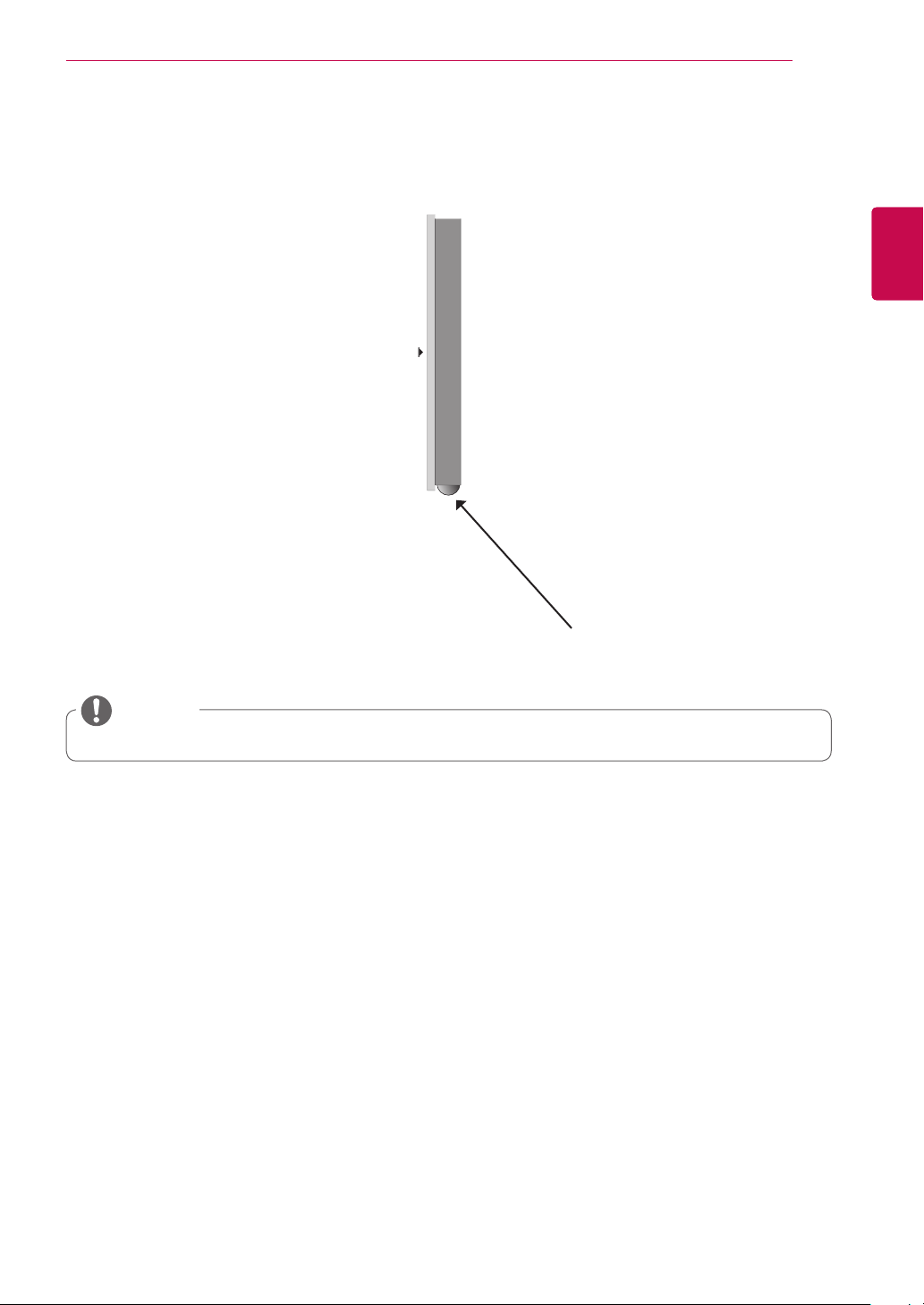
Storage method for panel protection
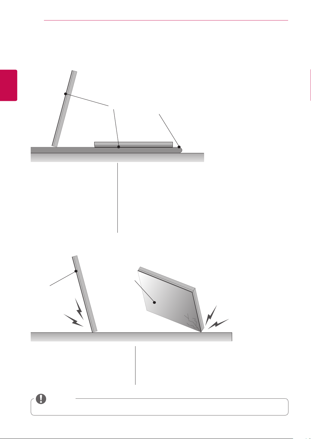
Correct method
If the product needs to be
set upright, hold both sides
of the product, and tilt backward carefully for the panel
not to touch the floor. (The
setting upright of the set is
possible with the outer
frame)
Incorrect method
Panel
Panel
When laying down the product, lay a cushion on a flat
floor, and put the product on
it with the panel of the product facing down.
Panel
Cushion
If the product is tilted to the
side of the panel, the bottom
of the panel may be damaged.
NOTE
y Handle the product with care. The product may be damaged by shocks.
If the product is tilted to the
edge of the panel, the edge
of the panel may be damaged.
ASSEMBLING AND PREPARING
13
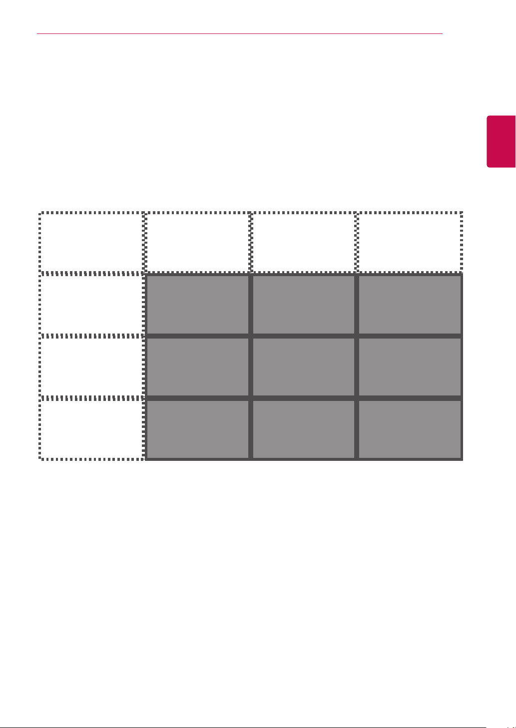
Panel array
Depending on usage and installation methods, the panels can be arranged in any format between 1x1 and
11x11.
Place each set as show in the fiqure below
Front
ENGENGLISH
minimum : 1x1 maxmum : 11x11
ENGLISH
ENG
ASSEMBLING AND PREPARING
14
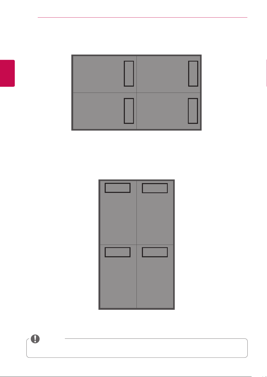
Landscape type back
minimum : 1x1 maxmum : 11x11
Portrait type back
minimum : 1x1 maxmum : 11x11
NOTE
y In portrait type, panels must be installed so that the input ports are placed at the top of the set.
ASSEMBLING AND PREPARING
15
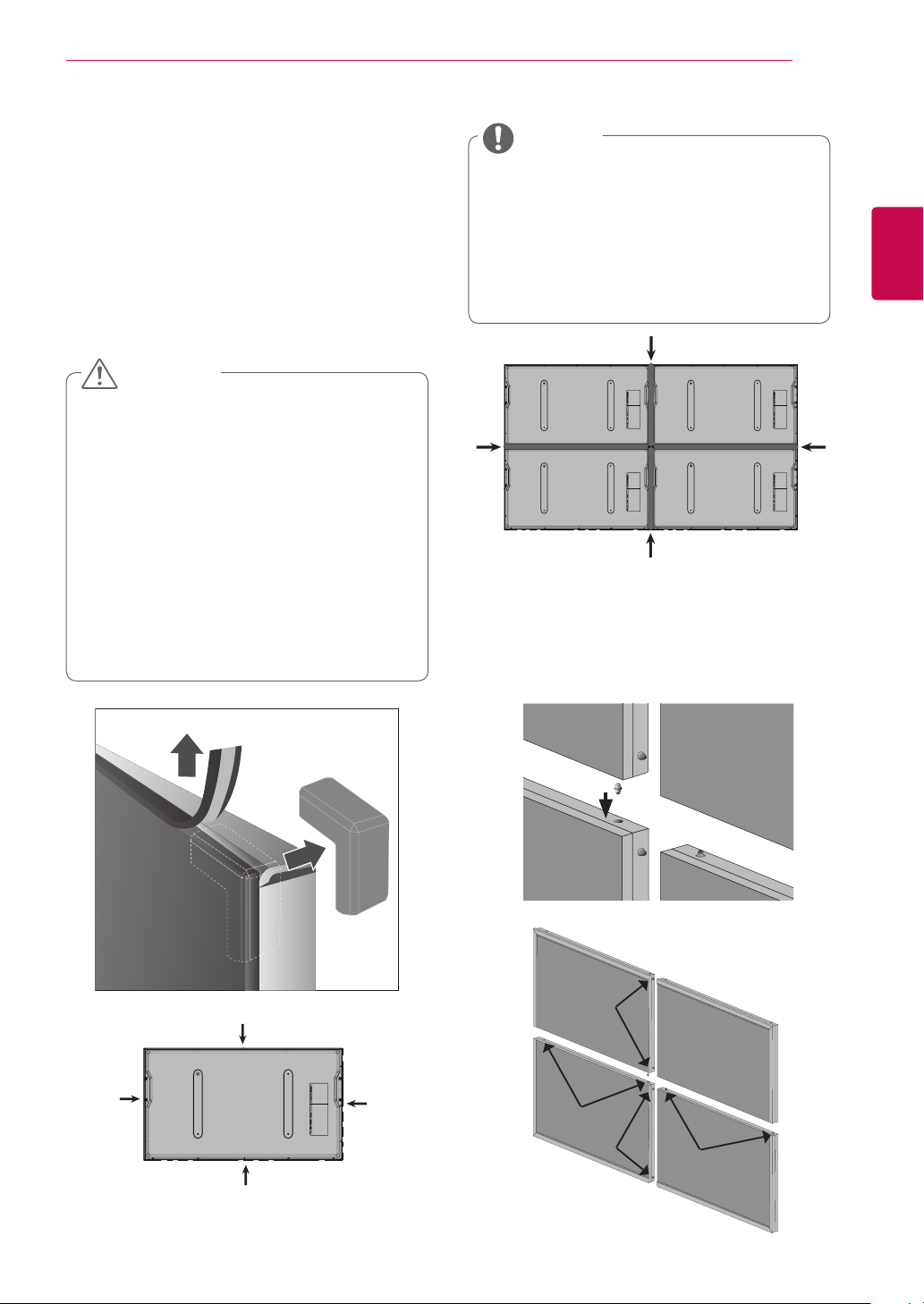
Installation method for panel protection
When you open the box, you will see that
protection covers are attached to the weak parts of
the product.
Place the set on the bracket, and remove the
protection covers just before finishing installation
by securely attaching it to the bracket.
CAUTION
y After removing the panel protection
cover, install the sets by tightly attaching
them.
y When removing the panel protection
cover, foreign substances may be stuck
to it, however, this does not affect the
performance. If necessary, please
remove them with the cotton flannel
provided.
y Excessive pressure may cause damage
to the product.
y Please wipe out residues, if any, after
removing the protective cover.
NOTE
To make the area behind the seam
y
between the sets invisible after securely
placing the set on the bracket, attach the
felt provided to the area.
Attach the felt provided between the
y
back of the sets in the same way for both
landscape and portrait types.
Guide pin
Guide pins are useful to align the sets.
Insert Guide pins as shown in the figure below.
ENGENGLISH
Rubber tape
Insertion &
Assembly
ENGLISH
ENG
ASSEMBLING AND PREPARING
16
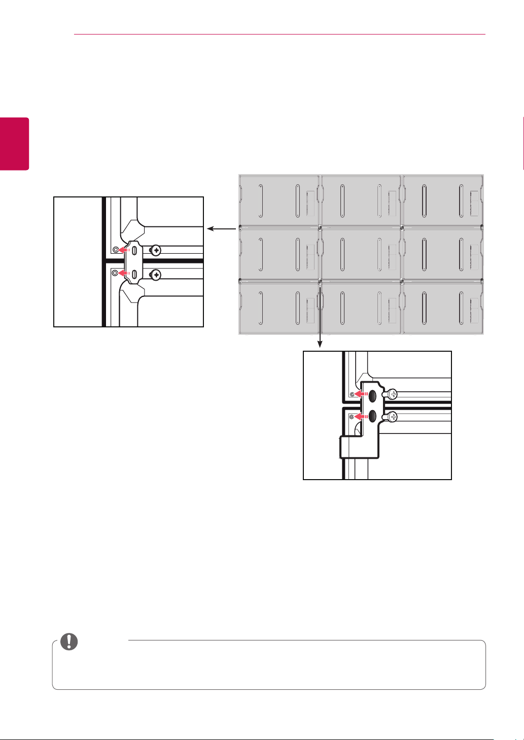
Guide Fixer
Align the sets using guide pins before installing a guide fixer. This ensures that the sets are aligned
properly.
Align a guide fixer with the holes and fasten them with the screws.
1
When installation of the sets is complete, attach the protection cushion provided.
2
NOTE
For a portrait type, there is also a fixer fixing point in the center.
Its position can be changed if necessary.(You do not have to use them all.)
ASSEMBLING AND PREPARING
17
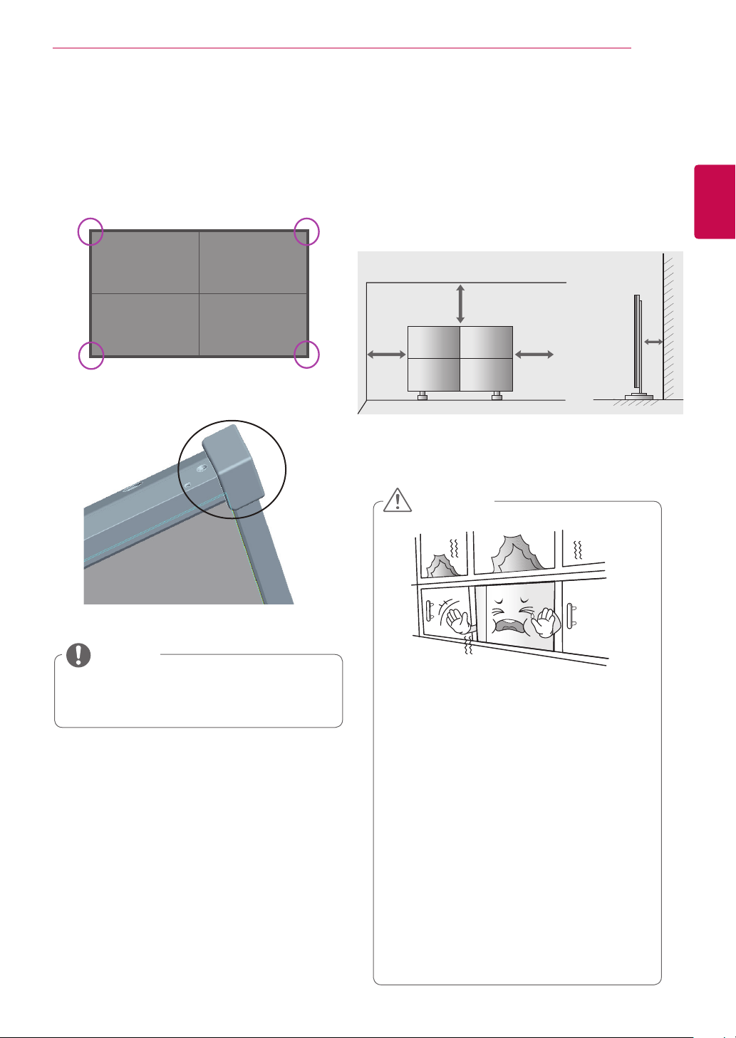
Protection cushion attachment
We recommended that you attach the
y
protection cushion, as shown in the picture
below, to prevent damage.
Transportation method for panel protection
Image shown may differ from your monitor.
y
For adequate ventilation and maintenance service,
secure a minimum distance of 20 cm as shown
below before installation.
15 cm
20 cm
20 cm
CAUTION
20 cm
ENGENGLISH
NOTE
y It is recommended that you attach a
separate frame to the edge of the set to
prevent damage.
y When sets are built in to a wall, the
internal temperature may rise to such an
extent that it causes overheating, which
may lead to a fire. To prevent the set from
overheating, please follow the instructions below.
y Avoid completely sealed installation.
y To ensure adequate ventilation, keep the
top, the bottom and the sides of the set
a minimum of 20 cm from the wall. (The
back of the set should be a minimum of
15 cm from the wall.)
y If there is not enough space, a separate
ventilation device is required.
y If you install four or more sets on top of
one another, you will need to ensure a
ventilator is used. (for example, a forced
draft fan.)
ASSEMBLING AND PREPARING
18
ENGLISH
ENG
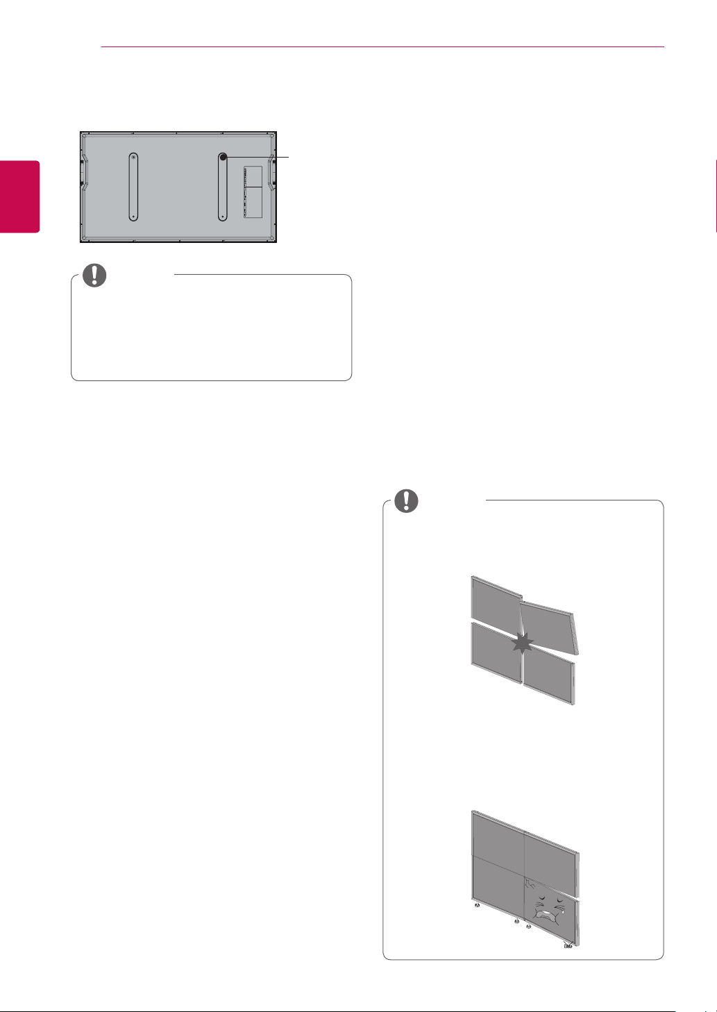
Set mount screw
NOTE
y Use a M8 screw for a wall mount screw
hole.
y The insertion depth of the screw should
be at least 8 mm.
Cautions on installation
Stand type
Screw
- Do not install the product in a location where
vibration or shock is likely to occur. Objects may
be dropped on the product causing damage to it.
- Do not install the product next to a sprinkler
sensor. The sprinkler may operate accidentally
because of the heat from the product.
- Do not install the product near high-tension wires.
The image on the screen may not be properly
displayed.
- Do not install the product near a heater. This may
cause product malfunction.
Wall-mount type
- Check whether the wall is stable enough to install
the product. If the wall is weak, it may cause an
accident. Reinforce the wall before installation.
- Secure enough space for cabling before finishing
the wall mounting process.
NOTE
y Put down a panel slowly during installa-
tion to avoid panel damage by bumping
into each other.
y When adjusting the interval between the
sets, make sure that the sets are balanced vertically and horizontally. If the
set is tilted as shown in the figure, this
may cause damage to the product due to
interference between the edges.
ASSEMBLING AND PREPARING
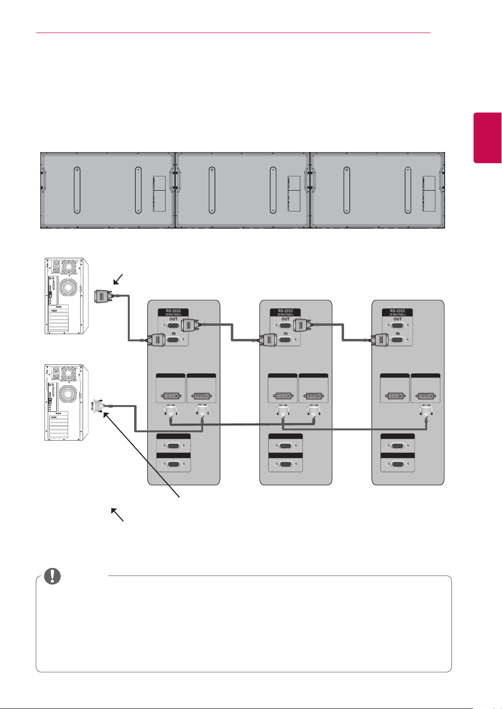
Video and Control Connector
Use this feature to input the same video or control signals into all products.
19
To use panels together, link one end of the cable to the OUT connector of one panel, and the other
y
end to the IN connector of another panel.
BACK PANEL
RS-232C Cable (Maximum 15 m)
RS-232C
DVI OUT DVI IN
DVI OUT DVI IN
DVI OUT DVI IN
ENGENGLISH
RGB OUT
RGB OUT
RGB OUT
DVI
RGB IN
RGB IN
RGB IN
DVI connection (Maximum 5 m)
RGB connection (Maximum 5 m)
RGB
NOTE
y This connection is supported only in RGB, DVI and RS-232C.
y If you need longer connection, please use DVI boosters or DVI fiber-optic cable.
y The maximum length of the cable from the video equipment to the panel is 5 m (RGB, DVI compo-
nent, HDMI).
y Up to four RGB/DVI connections are supported. (If you want to add any more, we recommended
that you use a distributor.)
y For RS232C, up to 20 connections are supported.
ENGLISH
DVI OUT DVI IN
(SERVICE ONLY)
USB
HDMI
RGB OUT
RGB IN
SPEAKER
(8)
AC-IN
DVI OUT DVI IN
(SERVICE ONLY)
USB
HDMI
RGB OUT
RGB IN
SPEAKER
(8)
TX
RX
CONTROL
DVI OUT DVI IN
(SERVICE ONLY)
USB
HDMI
RGB OUT
RGB IN
SPEAKER
(8)
DVI OUT DVI IN
(SERVICE ONLY)
USB
HDMI
RGB OUT
RGB IN
SPEAKER
(8)
TX
RX
CONTROL
AC-IN
TX
RX
CONTROL
AC-IN
AC-IN
TX
RX
CONTROL
ENG
ASSEMBLING AND PREPARING
20
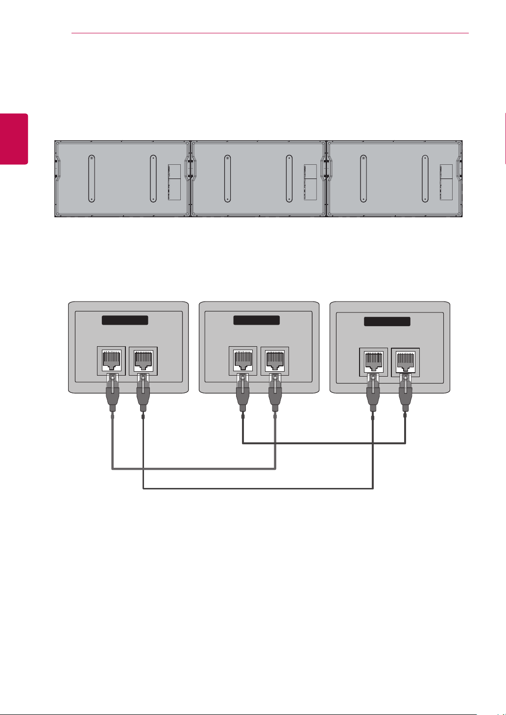
Brightness Adjustment Connector
It is a connector to compensate the luminance difference, and connect it using the LAN Cable inside the
Accessory box.
BACK PANEL
Connect LAN Cable to TX, and connect to RX connector of other sets.
CONTROL
RX TX
CONTROL
RX TX
CONTROL
RX TX
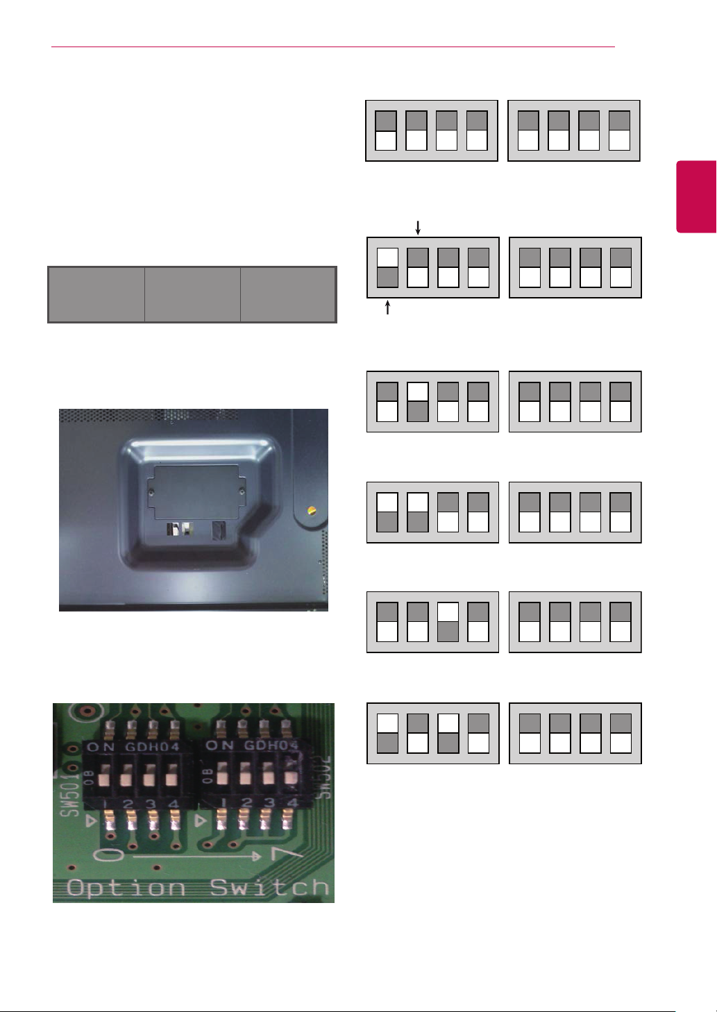
Dip switch setting
OFF
ON
1 2 3 4 1 2 3 4
OFF
ON
1 2 3 4 1 2 3 4
1 2 3 4 1 2 3 4
OFF
ON
1 2 3 4 1 2 3 4
1 2 3 4 1 2 3 4
1 2 3 4 1 2 3 4
OFF
ON
1 2 3 4 1 2 3 4
1 2 3 4 1 2 3 4
1 2 3 4 1 2 3 4
1 2 3 4 1 2 3 4
OFF
ON
1 2 3 4 1 2 3 4
1 2 3 4 1 2 3 4
1 2 3 4 1 2 3 4
1 2 3 4 1 2 3 4
1 2 3 4 1 2 3 4
To control each monitor separately, set up monitor
ID using the dip switch.
The far left monitor becomes #1 when you stand
in front of the monitors. Number the monitors in
sequence from the far left to right.
ASSEMBLING AND PREPARING
1 2 3 4 1 2 3 4
Factory reset
21
ENGENGLISH
1 2 3
1 Open the cover at the marked position on the
back of each monitor.
2 Start setting up from #0 switch as shown in the
figure below.
1 2 3 4 1 2 3 4
monitor #1
1 2 3 4 1 2 3 4
monitor #2
1 2 3 4 1 2 3 4
monitor #3
1 2 3 4 1 2 3 4
monitor #4
1 2 3 4 1 2 3 4
monitor #5
ENGLISH
ENG
ASSEMBLING AND PREPARING
22
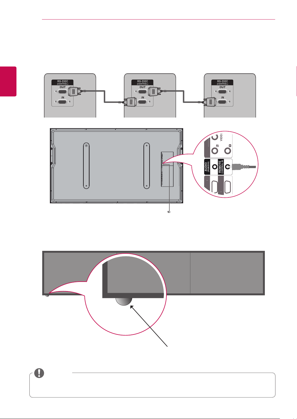
IC Receiver
It has the role of enabling to receive the signal of the remote control by connecting to the set.
RS-232C Cable
Front
Remote Control Sensor
NOTE
y Install the IR receiver in the first set connected to the computer and the RS-232C cable.
y The IR signal of the remote control is sent through the RS-232C cable in cascade.
Side
FRONT
ASSEMBLING AND PREPARING
23
ENGENGLISH
Remote Control Sensor
NOTE
y Attach the remote control sensor to the middle cabinet (BK frame).
 Loading...