

LG 60PC1D, 60PC1D-AA Service Manual
PLASMA TV
SERVICE MANUAL
CAUTION
BEFORE SERVICING THE CHASSIS,
READ THE SAFETY PRECAUTIONS IN THIS MANUAL.
CHASSIS : PB61A
MODEL : 60PC1D 60PC1D-AA
website:http://biz.LGservice.com

- 2 -
CONTENTS
SAFETY PRECAUTIONS ....................................................................................3
SPECIFICATIONS ................................................................................................4
ADJUSTMENT INSTRUCTIONS .........................................................................6
TROUBLE SHOOTING GUIDE ..........................................................................11
BLOCK DIAGRAM.............................................................................................17
EXPLODED VIEW..............................................................................................18
EXPLODED VIEW PARTS LIST ........................................................................19
REPLACEMENT PARTS LIST...........................................................................20
SCHEMATIC DIAGRAM.........................................................................................
PRINTED CIRCUIT DIAGRAM ..............................................................................
- 3 -
SAFETY PRECAUTIONS
Many electrical and mechanical parts in this chassis have special safety-related characteristics. These parts are identified by in the
Schematic Diagram and Replacement Parts List.
It is essential that these special safety parts should be replaced with the same components as recommended in this manual to prevent
X-RADIATION, Shock, Fire, or other Hazards.
Do not modify the original design without permission of manufacturer.
General Guidance
An isolation Transformer should always be used during the
servicing of a receiver whose chassis is not isolated from the AC
power line. Use a transformer of adequate power rating as this
protects the technician from accidents resulting in personal injury
from electrical shocks.
It will also protect the receiver and it's components from being
damaged by accidental shorts of the circuitry that may be
inadvertently introduced during the service operation.
If any fuse (or Fusible Resistor) in this monitor is blown, replace it
with the specified.
When replacing a high wattage resistor (Oxide Metal Film Resistor,
over 1W), keep the resistor 10mm away from PCB.
Keep wires away from high voltage or high temperature parts.
Due to high vacuum and large surface area of picture tube,
extreme care should be used in handling the Picture Tube.
Do not lift the Picture tube by it's Neck.
Leakage Current Cold Check(Antenna Cold Check)
With the instrument AC plug removed from AC source, connect an
electrical jumper across the two AC plug prongs. Place the AC
switch in the on position, connect one lead of ohm-meter to the AC
plug prongs tied together and touch other ohm-meter lead in turn to
each exposed metallic parts such as antenna terminals, phone
jacks, etc.
If the exposed metallic part has a return path to the chassis, the
measured resistance should be between 1MΩ and 5.2MΩ.
When the exposed metal has no return path to the chassis the
reading must be infinite.
An other abnormality exists that must be corrected before the
receiver is returned to the customer.
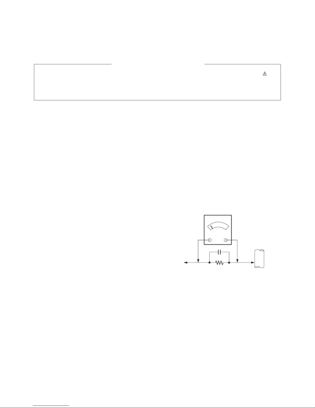
Leakage Current Hot Check (See below Figure)
Plug the AC cord directly into the AC outlet.
Do not use a line Isolation Transformer during this check.
Connect 1.5K/10watt resistor in parallel with a 0.15uF capacitor
between a known good earth ground (Water Pipe, Conduit, etc.)
and the exposed metallic parts.
Measure the AC voltage across the resistor using AC voltmeter
with 1000 ohms/volt or more sensitivity.
Reverse plug the AC cord into the AC outlet and repeat AC voltage
measurements for each exposed metallic part. Any voltage
measured must not exceed 0.75 volt RMS which is corresponds to
0.5mA.
In case any measurement is out of the limits specified, there is
possibility of shock hazard and the set must be checked and
repaired before it is returned to the customer.
Leakage Current Hot Check circuit
1.5 Kohm/10W
To Instrument's
exposed
METALLIC PARTS
Good Earth Ground
such as WATER PIPE,
CONDUIT etc.
AC Volt-meter
IMPORTANT SAFETY NOTICE
0.15uF
SPECIFICATIONS
NOTE : Specifications and others are subject to change without notice for improvement
.
V Application Range
This spec is applied to the 360” PLASMA TV used PB61A Chassis.
V Specification
Each part is tested as below without special appointment.
1) Temperature : 25±5°C (77±9°F), CST : 40±5
2) Relative Humidity: 65±10%
3) Power Voltage: Standard Input voltage (100-240V~, 50/60Hz)
* Standard Voltage of each product is marked by models.
4) Specification and performance of each parts are followed each drawing and specification by part number in accordance with SBOM.
5) The receiver must be operated for about 20 minutes prior to the adjustment.
V Test Method
1) Performance : LGE TV test method followed.
2) Demanded other specification
Safety : CB specification
EMC : CISPR 13 specification
V General Specification
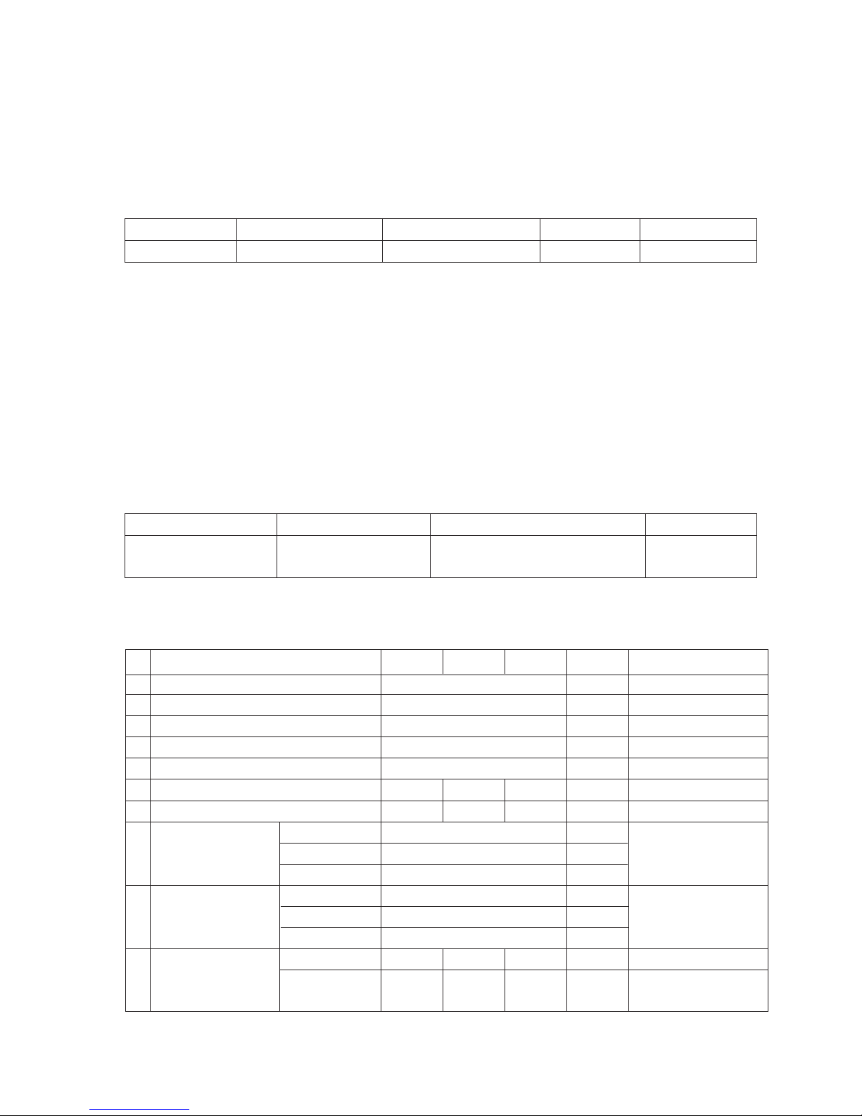
1. Module Specification(PDP60X6)
- 4 -
Display area
Outline dimension
Number of Pixels
Cell pitch
Color arrangement
Weight(net)
Weight(gross)
Operation Environment Temperature
Humidity
Pressure
Storage Environmnet Temperature
Humidity
Pressure
I mage stick minimization Start time
mode Low Brightness
Arrival Time
1319.6 (H) * 741.9(V) °± 0.5
1408 (H) x 828 (V) x 61 (D)° ± 1
1366 (H) x 768(V)
322um (H) x 966um (V)
RGB closed type
32.0 33.0 32.0
122.0 123.0 124.0
0 ~ 40
20 ~ 80
800 ~ 1100
-20 ~ 60
10 ~ 90
700 ~ 1100
4.5 5 5.5
14 15 16
1
2
3
4
5
6
7
8
9
10
No Item Remark
1Pixel=3RGB Cells
Green Cell basis
5EA 1 Box
Altitude : 0 to 2000M
Altitude : 0 to 3000M
Chassis
PB61A 60PC1D-AA Australia LG
Model Name Market Brand Remark
60PC1D-AA Safety : IEC60065,EN60065
EMC : CISPR 13 Class B
Australia
Model ApplianceMarket Remark
mm
mm
um
Kg
Kg
deg
%
hPa
deg
%
hPa
min
min
Min Typ Max Unit

- 5 -
2. Model General Specification
Broadcasting system
Available Channel
Tuner IF
Input Voltage
PDP Module
Aspect ratio
Operating Temperature
Operating Humidity
Storage Temperature
Storage Humidity
PAL-B/G, DTV : DVB-T
1) VHF : 00 ~ 12
2) UHF : 20 ~ 75
3) CATV : 02 ~ 44
4) DTV : 06 ~12, 27 ~ 69
1) PAL : 38.90MHz(Picture),
34.40MHz(Sound)
2) DVB-T : 36.125MHz
240V~, 50Hz
PDP60X6
16:9 (wide)
0 40 deg
85 %
-20 60 deg
85 %
1
2
3
4
5
6
7
8
9
10
No
Item
Remark
Maker : LGE
? Closed Type
Specification
Min Typ Max Unit

- 6 -
ADJUSTMENT INSTRUCTIONS
1. Application Object
These instructions are applied to all of the 60” PLASMA TV,
PB61A
Chassis.
2. Notes
(1) Because this is not a hot chassis, it is not necessary to use
an isolation transformer. However, the use of isolation
transformer will help protect test equipment.
(2) Adjustments must be done in the correct order.
(3) The adjustments must be performed in the circumstance of
25±5°C of temperature and 65±10% of relative humidity if
there is no specific designation.
(4) The input voltage of the receiver be must kept 220V~,
60Hz when adjusting.
(5) The receiver must be operational for about 15 minutes
prior to the adjustments.
O Preliminary action is applied to the test for afterimage
discharge detection, and 100% FULL WHITE PATTERN
must be operated automatically.
O Test for afterimage discharge detection
1) After pressing Power Only key(only operating by
pressing Power Only key), Full Test Pattern(2 min
30sec) --> Full Black Pattern(30sec) --> After this state,
Full White Pattern is displayed.
(but you must preset the program for Full White State
when you press the Main Power Off/On)
2) Pattern Mode is deselected by pressing CH +/-, Exit Key.
[ Set is activated HEAT-RUN without signal generator in
this mode.
3. CPLD Download
(1) Test Equipment: PC, Jig for download
(2) Connect the power of VSC B/D.
(3) Execute download program of PC.
(4) After executing the hot key on the Programmer, click icon.
(5) End after confirming.
4. Sub-ucom(MTV) Download
(1) Test Equipment: PC, Jig for download
(2) Connect the power of VSC B/D.
(3) Execute download program of PC.
(4) After executing the hot key on the Programmer, click icon.
(5) End after confirming.
5. MST3362M-Set Adjustment
5-1. Synopsis
MST3362M-Set adjustment to set the black level and the Gain
of optimum with an automatic movement from the analog =>
digital converter.
5-2. Test Equipment
Service R/C, 801GF(802B,802F,802R),
MSPG-925 Pattern Generator.
( 480i, 1080i 60Hz Color Bar Pattern output will be possible
and the output level will accurately have to be revised with
0.7±0.1Vp-p)
5-3. Adjustment
(1) How to adjustment the Component1
1) Select Component1 as the input with Color Bar Pattern
in 480i 60Hz mode and select ‘Component1’ on screen.
2) After receiving signal for at least 1 second, press the
ADJ Key on the Service R/C to enter the ‘Ez - Adjust’
and select the ‘1. ADC 480i Comp1’. Pressing the Vol+
Key to adjust the component1.
3) When the adjustment is over, 'Component1 Adjustment
OK’ is displayed. If the adjustment has errors,
'Component1 Adjustment Failed! Try Again!’ is
displayed.
4) Readjust after confirming the case Pattern or adjustment
condition where the adjustment had errors.
5) After adjustment is complete, exit the adjustment mode
by pressing the ADJ KEY.
(2) How to adjustment the Component2, RGB
1) Select Component2, RGB-DTV as the input with Color
Bar Pattern in 1080i 60Hz mode and select
‘Component2’ on screen.
2) After receiving signal for at least 1 second, press the
ADJ Key on the Service R/C to enter the ‘Ez - Adjust’
and select the ‘2. ADC 1080i Comp2/RGB’. Pressing
the Vol+ Key to adjust the component2.
3) When the adjustment is over, 'Component2 Adjustment
OK’ is displayed. If the adjustment has errors,
'Component2 Adjustment Failed! Try Again!’ is
displayed. and If the adjustment has errors, 'RGB
Adjustment Failed! Try Again!’ is displayed.
4) Readjust after confirming the case Pattern or adjustment
condition where the adjustment had errors.
5) After adjustment is complete, exit the adjustment mode
by pressing the ADJ KEY.
PC
VSC
B/D
JIG cable(CPLD D/L )
<Fig. 1> Connection Diagram of CPLD Download
(Fig. 2) Adjust Pattern : 480i, 1080i 60Hz Color Bar Pattern
Caution) If you turn on a still screen more than 20 minutes
(Especially Digital pattern, Cross Hatch Pattern), an afterimage
may occur in the black level part of the screen.
- 7 -
6. Video(uPD)-Set
6-1. Synopsis
This is a adjustment to reduce the color difference of video
signal Main/Sub Display.
6-2. Required Equipment
Service R/C, MSPG-925 Pattern Generator.
(It’s available to output the Color Bar Pattern of the NTSC,PAL)
6-3. Adjustment
(1) How to adjustment the uPD PAL
1) Select AV1 as the input with 100% 8 Color Bar Pattern
in PAL mode and select ‘AV1’ on screen.
2) After receiving signal for at least 1 second, press the
ADJ Key on the Service R/C to enter the ‘Ez - Adjust’
and select the ‘3. uPD PAL(Main&Sub)-Set’. Pressing
the Vol+ Key to adjust the uPD PAL.
3) When the adjustment is over, 'uPD64015 PAL Main
Adjustment OK’ and ‘uPD64015 PAL Sub Adjustment
OK’ is displayed. If the adjustment has errors,
'uPD64015 PAL Main Error!’ or 'uPD64015 PAL Main
Error!’ is displayed.
4) Readjust after confirming the case Pattern or adjustment
condition where the adjustment had errors.
5) After adjustment is complete, exit the adjustment mode
by pressing the ADJ KEY.
(2) How to adjustment the uPD NTSC
1) Select AV1 as the input with 100% 8 Color Bar Pattern
in NTSC mode and select ‘AV1’ on screen.
2) After receiving signal for at least 1 second, press the
ADJ Key on the Service R/C to enter the ‘Ez - Adjust’
and select the ‘4. uPD NTSC(Main&Sub)-Set’. Pressing
the Vol+ Key to adjust the uPD NTSC.
3) When the adjustment is over, 'uPD64015 NTSC Main
Adjustment OK’ and ‘uPD64015 NTSC Sub Adjustment
OK’ is displayed. If the adjustment has errors,
'uPD64015 NTSC Main Error!’ or 'uPD64015 NTSC
Main Error!’ is displayed.
4) Readjust after confirming the case Pattern or adjustment
condition where the adjustment had errors.
5) After adjustment is complete, exit the adjustment mode
by pressing the ADJ KEY.
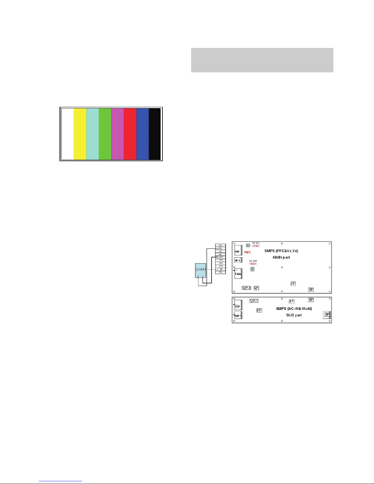
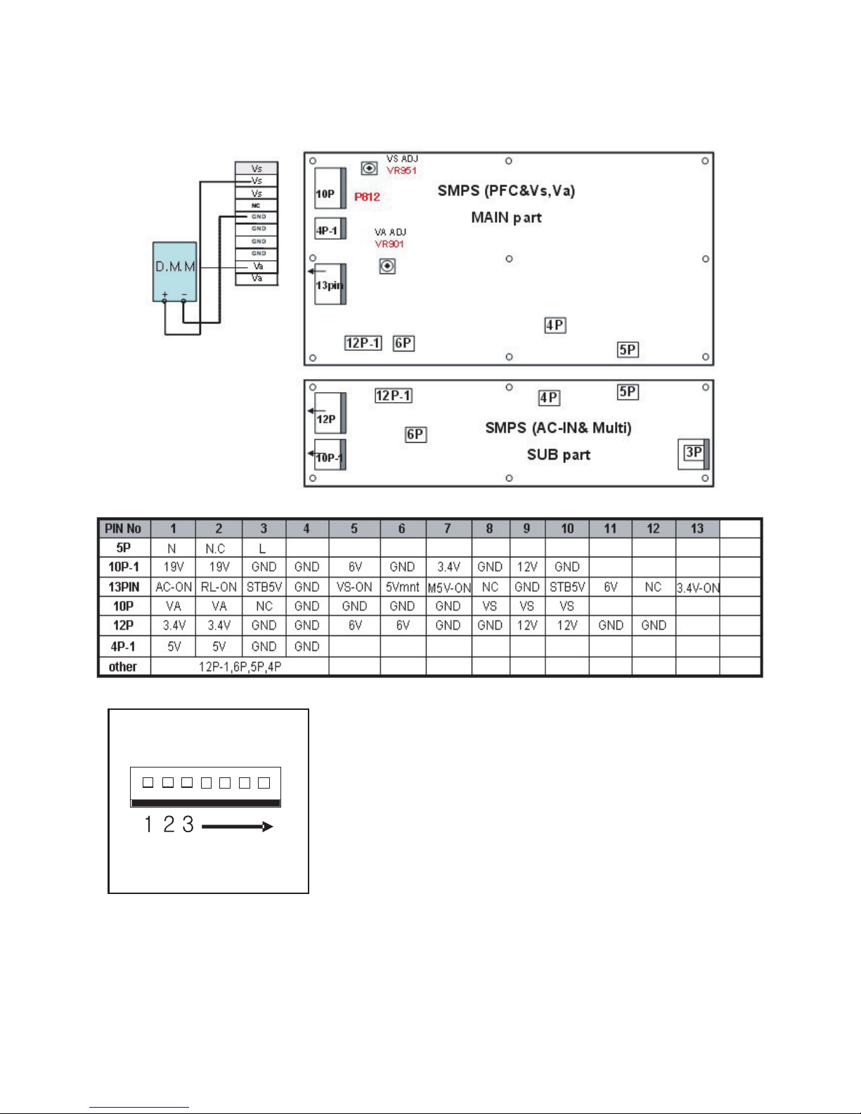
7. POWER PCB Assy Voltage
Adjustment (Va, Vs Voltage Adjustment)
7-1. Test equipment: D.M.M 1EA
7-2. Connection Diagram for Measuring
Refer to Fig.5
7-3. Adjustment Method
Adjustment Method for Power Board( P/No: EAY32961801)
(1) Va Adjustment
1) After receiving 100% Full White Pattern, HEAT RUN.
2) Connect + terminal of D.M.M to Va pin of P812, connect
- terminal to GND pin of P812.
3) After turning VR901, voltage of D.M.M adjustment as
same as Va voltage which on label of panel right/top.
(Deviation; ±0.5V)
(2) Vs Adjustment
1) Connect + terminal of D.M.M to Vs pin of P812, connect
– terminal to GND pin of P812.
2) After turning VR951, voltage of D.M.M adjustment as
same as Va voltage which on label of panel right/top.
(Deviation; ±0.5V)
(Fig. 3) Adjust Pattern :100% 8 Color Bar Pattern
Each PCB Assy must be checked by Check JIG Set before
assembly. (Especially, be careful Power PCB Assy which can
cause Damage to the PDP Module.)
(Fig. 5) Connection Diagram of Power Adjustment for Measuring
- 8 -
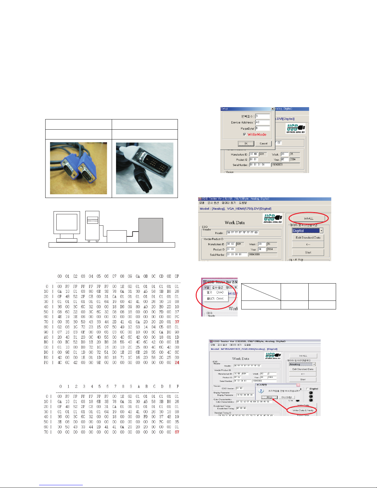
8. EDID(The Extended Display
Identification Data)/DDC
(Display Data Channel) Download
This is the function that enables “Plug and Play".
8-1. Required Test Equipment
(1) PC, Jig for adjusting DDC.
(PC serial to D-sub Connection equipment)
(2) DVI to HDMI Connector.
8-2. Setting of Device
8-3. EDID DATA
(1) HDMI EDID DATA.
(2) RGB EDID DATA.
8-4. Act or set the EDID S/W
1) As above Fig. 6, Connect the Set, EDID Download Jig, PC
& Cable.
2) Turn on the PC & EDID Download Jig. And Execute the
S/W : EDID TESTER Ver,2.5.
3) Set up S/W option.
Repeat Number : 3
Device Address : A0
PageByte : 8
8-5. How to use the EDID S/W
1) Init the data.
2) Load the EDID data.(Open File)
3) Press the “Write Data & Verify”button. and input the
data.
4) If the writing is finished, you will see the “OK” message.
Analog EDID
D-sub to D-sub
HDMI EDID
DVI-D to HDMI
PC
JIG
PDP
SET
RGB
(Analog)
67
Checksum
Model
60PC1D-AA
HDMI
(Digital)
3724

- 9 -
9. Adjustment of White Balance
9-1. Required Equipment
(1) Color analyzer (CA-100 or similar product)
(2) Automatic adjustor (with automatic adjustment hour
necessity and the RS-232C communication being possible)
9-2. Connection Diagram of Equipment
for Measuring (Automatic Adjustment)
9-3. Process of automatic adjustment
(1) As using the white pattern for adjustment the inner part,
HDMI connection need not. But as lower part, the RS-232C
Command is used.
Wb 00 00 Automatic adjustment of white balance start.
Wb 00 10 The start of gain adjustment.(inside pattern)
Ja 00 ff Adjustment Date.
Jb 00 c0
...
Wb 00 1f The end of gain adjustment.
As occasion demands , adjust the offset.
( Wb 00 20(Start) , Wb 00 2f(end))
Wb 00 ff Automatic adjustment of white balance end.
(Disappear the inside pattern)
Caution) When you adjust, automatically, RS-232C
Command is used.
[[
RS-232C Command (Automatic Adjustment)
9-4. Adjustment of White Balance
(Automatic Adjustment)
O
Calibrate of the CA-100, then attach sensor to PDP module
surface when you adjust.
O
Manual adjustment is also possible by the following sequence.
(1) HEAT RUN at least 30 minutes by pressing the Power only
Key on the Service Remote Control and adjust. and use
power only or tint key and establish BaudRate to 115200.
(2) It must start “ 00 00”, complete “wb 00 ff”.
(3) Adjust offset.
9-5. Adjustment of White Balance
(Passivity Adjustment)
(1) HEAT RUN at least 30 minutes by pressing the ‘7. White-
Pattern’ on the Service Remote Control and adjust.
(2) After attaching sensor to center of screen, select ‘6. White-
Balance’ of ‘Ez - Adjust’ by pressing the ADJ KEY on the
Service R/C. Then enter adjustment mode by pressing the
Right KEY (
G
). This time white pattern is displayed.
(3) When fix R GAIN in 192,
- make the adjustment reducing the value of G GAIN and
B GAIN less than 192.
When fix G GAIN in 192,
- make the adjustment reducing the value of R GAIN and B
GAIN less than 192.
When fix B GAIN in 192,
- make the adjustment reducing the value of R GAIN and G
GAIN less than 192.
* Fix : R OFFSET=64, G OFFSET=64, B OFFSET=64
(4) Adjust using Volume +/- KEY.
Value of bright : High Level -> 216gray
[Cool]
X; 0.276±0.002 Y; 0.282±0.002
Color temperature: 11000°K ±1000°K
dUV: -3dUV
[Medium]
X; 0.285±0.002 Y; 0.294±0.002
Color temperature: 9300°K±1000°K
dUV: -3dUV
[Warm]
X; 0.314±0.002 Y; 0.323±0.002
Color temperature: 6300°K±1000°K
dUV: -3dUV
(5) Move the the Ez-Adjust screen by pressing the
V KEY
and exit the adjustment mode by pressing the ADJ KEY.
216 FULL WHITE
CVBS Part
PDP MONITOR
COLOR
ANALYZER
TYPE; CA-100
<Fig. 6> Connection Diagram of Automatic Adjustment
R Gain
G Gain
B Gain
R Offset
G Offset
B Offset
CENTER
(DEFAULT)(Hex)
00
00
00
00
00
00
D0
D0
D0
7f
7f
7f
Min
Max
(Hex)
C0
C0
C0
40
40
40
Cool
C0
C0
C0
40
40
40
Mid
C0
C0
C0
40
40
40
Warm
RS-232C COMMAND
[CMD ID DATA]
Jg
Jh
Ji
lp
lq
lr
Cool
Ja
Jb
Jc
lj
lk
ll
Mid
Jd
Je
Jf
Lm
Lm
Lo
Warm
00
00
00
00
00
00
00
10
1f
20
2f
ff
Automatic adjustment of white balance start.
The start of gain adjustment.(inside white pattern)
The end of gain adjustment.
The start of Offset adjustment.(inside white pattern)
The end of Offset adjustment.
Automatic adjustment of white balance end.
(Disappear the inside pattern)
wb
wb
wb
wb
wb
wb

- 10 -
10. Check the adjustment of the plant
shipping mode
: This adjustment is checking the set state after take a
adjustment of examination, check state of this model as
shown below pressing the IN_STOP button on the
adjustment Remote Controller.
1
2
3
4
5
6
7
8
9
10
Digital
30
Off
16:9
1
Dynamic
Cool
Off
Auto
Standard
Off
0
On
On
--
Off
Off
Off
16:9
Off
Normal
Off
C0, C5, C6, S11,
C20, C35, C52, C68
C43
Item ConditionNo
Remark
Input Mode
Volume Level
Mute
Aspect Ratio
SET ID
Picture PSM
Color Temp.
Advanced Cinema
Black level
Sound SSM
AVL
Balance
TV Speaker
Time Auto Clock
Manual Clock
Off Timer / On Timer
Sleep Timer / Auto Off
Option Sub title
Child Lock
ARC
Demo
ISM Method
Low Power
Channel Memory Analog
Digital

- 11 -
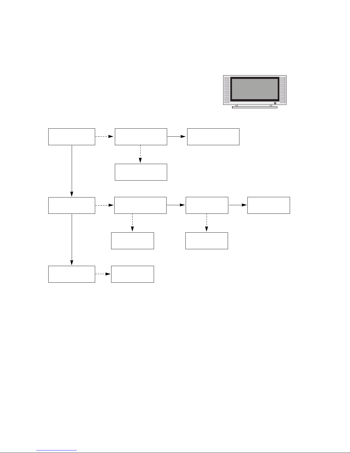
TROUBLE SHOOTING GUIDE
1. Power Board
1-1. The whole flowchart which it follows in voltage output state
Start check
Manufacture enterprise
meaning of a passage
1. Check the Power Off
condition.
Doesn't the
screen whole come
out?
Is it identical
with Power Off
condition?
Yes
Yes
No
No
No
No
No
2. Check the Interface
signal condition.
Is the Interface
signal operated?
Yes
3. Check the St-by 5V
signal circuit.
Doesn't the
low pressure output
come out?
Doesn't the
St-by 5V signal
come out?
Yes
Yes
No
4. Check the 5V Monitor
signal circuit.
Doesn't the
5V Monitor signal
come out?
Yes
7. Check the VSC Vs-ON
signal
Doesn't the
high tension output
come out?
Doesn't the
VSC signal Vs-ON
come out?
Yes
Yes
Does
high tension
output voltage Drop
occur?
When the
Y B/D Module
input connector is
removed, does output
voltage drop
occur?
When the
Y, Z B/D Module
input connector is remove,
does Power Board hightension
output voltage Drop
occur?
Yes No No
9. Check the Power
Board Output high
tension circuit
Yes
10. Check the Z B/D
Module output circuit
Yes
When the
Z B/D Module
input connector is
removed, does output
voltage Drop
occurs?
11. Check the Y B/D
Module output circuit
Yes
No
8. Check the Vs, Va
voltage output circuit.
Doesn't the
Vs, Va voltage output
come out?
Yes
No
No
5. Check the VSC RL-ON
signal.
Doesn't the
VSC signal RL-ON
come out?
Yes
6. Check the VSC low
pressure output
Doesn't the
VSC low pressure
output come out?
Yes
- 12 -
1-2. 60” Power Board Structure
T901,T902 : Vs Trans
T801 : Va Trans
T201 : Low Voltage Trans & ST-BY Trans
L601,L602 : PFC Inductor
- 13 -
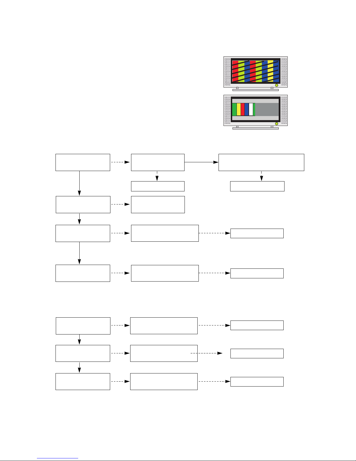
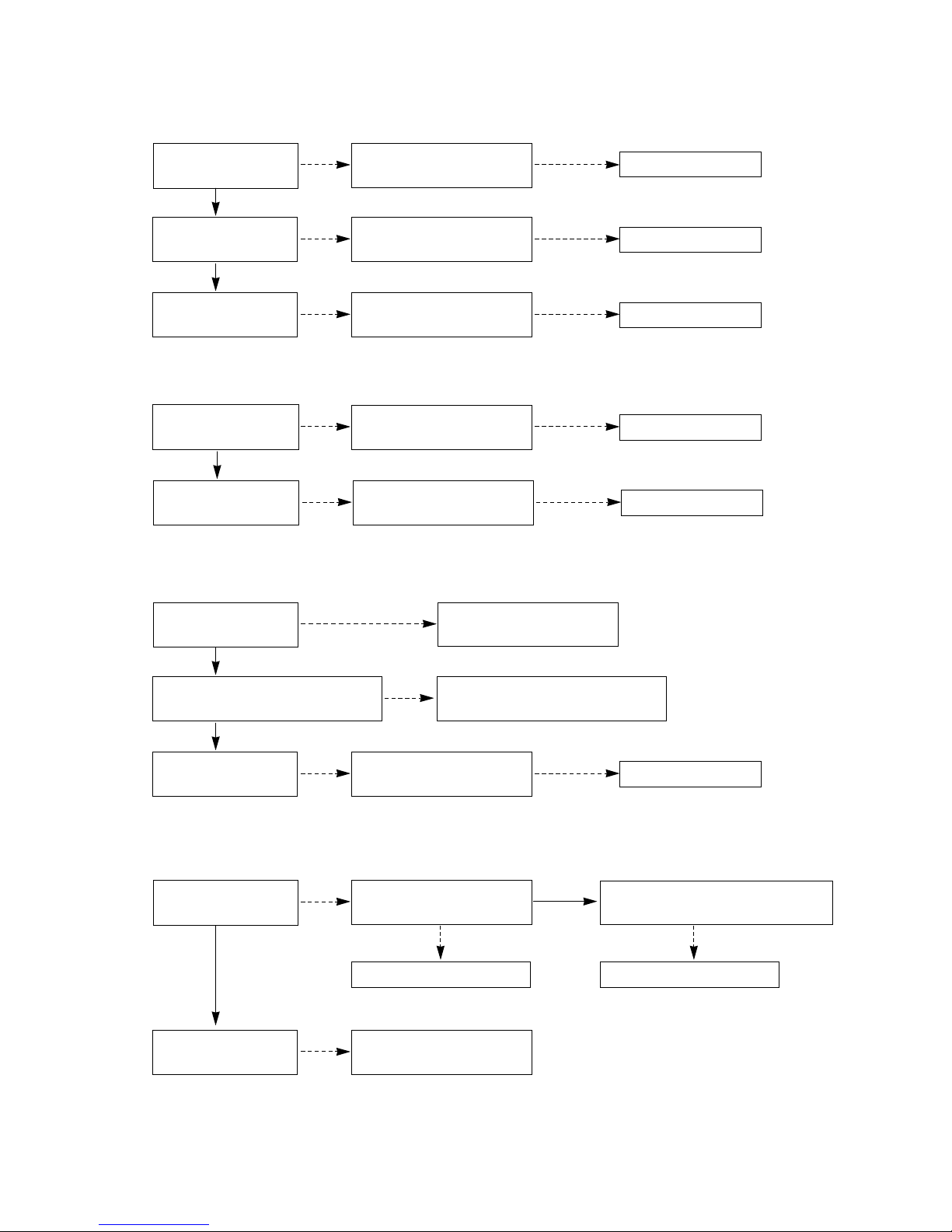
2. In case of occurring strange screen into specific mode
2-1. In case the OSD does not displayed
(1) Symptom
1) LED is white.
2) Some discharge on Panel becomes accomplished continuously.
(2) Check follow
Is the LVDS cable
normal ?
Is the VSC Board
normal?
Is the LVDS cable
connected well?
Cable inserts well.
Yes
No
No
Yes
Does the Thine IC
(IC900) Operates ?
Replace Thine
(IC900).
No
Is the Ctrl Board of
Module normal?
Replace Ctrl B/D.
No
No
Replace Scaler
(IC401).
No
Does the Scaler
(IC401) Operates ?
Replace VSC
Digital B/D.
Replace the cable.
Yes
Yes Yes
- 14 -
2-2. In case of does’t display the screen into specific mode
(1) Symptom
1) The screen does not become the display from specific input mode.
(RF, AV, Component, RGB, DVI)
(2) Check following
1) Check the all input mode should become normality display
.
2) Check the Video(Main)/Data(Sub), Video(Main)/Video(Sub) should become
normality display from the PIP mode or DW mode.
(Re-Check using Swap function)
Check the NEC64015(IC701) if the main picture is abnormal, and
Check the NEC64015(IC801) If the sub picture is abnormal.
(3) When Analog TV mode is abnormal
(4) When AV mode is abnormal
Is the Splitter normal?
Is the Flat Cables
normal?
Replace Flat Cables.
Is the Tuner Cable
connected well?
Cable inserts well.
Yes
No
No
Yes
Is the CXA2069Q(IC100)
normal?
Replace the Tuner.
No
Is the Input voltage, IIC Communication
and CVBS output normal?
No
Is normal the Input voltage, IIC
Communication and HV sync?
No
Replace the IC.
No
Yes
Is the uPD64015
normal?
Is normal the Input voltage, IIC
Communication and HV sync?
Is normal the Input voltage, IIC
Communication and HV sync?
Is normal the Input voltage, IIC
Communication and HV sync?
No
Replace the IC.
No
Is the CXA2069Q
normal?
Yes
Is the uPD64015
normal?
No
Replace the IC.
No
No
Replace the IC.
No
Is normal the Input voltage, IIC
Communication and HV sync?
Yes
Is the Scaler normal?
No
Replace the IC.
No
Yes
- 15 -
(5) When Component or RGB-DTV/ PC mode is abnormal
(6) When HDMI/DVI mode is abnormal
(7) When DVI-PC mode is abnormal
(8) When Digital TV mode is abnormal
Is normal the Input voltage, IIC
Communication and HV sync?
Is normal the Input voltage, IIC
Communication and HV sync?
Is the CXA2151Q(IC500)
normal?
Yes
Is the MST3362(IC604)
normal?
Is the MST3362(IC604)
normal?
No
Replace the IC.
No
No
Replace the IC.
No
Is normal the Input voltage, IIC
Communication and HV sync?
Yes
Is the Scaler normal?
No
Replace the IC.
No
Is normal the Input voltage, IIC
Communication and HV sync?
Is the EDID correct?
Yes
Is the latest version the Graphic card
driver of the PC?
Update the Graphic card driver with the
latest version.
No
No
Is normal the Input voltage, IIC
Communication and HV sync?
Yes
Is the Scaler normal?
No
Replace the IC.
Cable connected well.
No
Is the Tuner Cable connected
well?
No
Is normal the Input voltage, IIC
Communication and output of the tuner?
Is the Splitter normal?
Yes
Replace the Tuner.
Is the Flat Cables
normal?
No
Is normal the Input voltage, IIC
Communication and HV sync?
Replace the IC.
No
Is normal the Input voltage, IIC
Communication and HV sync?
Yes
Is the Scaler normal?
No
Replace the IC.
No
No
Replace the Tuner.
No
Yes
 Loading...