

LG MB-394, 594A Service Manual
MICROWAVE OVEN
SERVICE MANUAL
MODEL : MB-394A, MH-594A
CAUTION
BEFORE SERVICING THE UNIT, READ THE
SAFETY PRECAUTIONS IN THIS MANUAL.
CAUTIONS
¥ Be sure to check microwave leakage prior to
servicing the oven if the oven is operative prior to
servicing.
¥ The service personnel should inform the
manufacture importer, or assembler of any
certified oven unit found to have a microwave
emission level in excess of 5 mW/cm2and should
repair any unit found to have excessive emission levels
at no cost to the owner and should ascertain the cause
of the excessive leakage. The service personnel
should instruct the owner not to use the unit until the
oven has been brought into compliance.
¥ If the oven operates with the door open, the service
personnel should:
- Tell the user not to operate the oven.
- Contact the manufacturer.
¥ The service personnel should check all surface and
vent openings for microwave leakage.
¥ Check for microwave leakage after every servicing.
The power density of the microwave radiation leakage
emitted by the microwave oven should not exceed
4 mW/cm2. Always start measuring of an unknown field
to assure safety for operating personnel from radiation
leakage.
MEASURING MICROWAVE ENERGY
LEAKAGE
¥ Pour 275±15cc of 20±5¡C(68±9¡F) water in a beaker
which is graduated to 600 cc, and place the beaker
on the center of the turntable.
¥ Set the energy leakage monitor to 2,450 MHz and
use it following the manufacturer's recommended
test procedure to assure correct result.
¥ When measuring the leakage, always use the 2-
inch (5cm) spacer supplied with the probe.
¥ Operate the oven at its maximum output.
¥ Measure the microwave radiation using and
electromagnetic radiation monitor by holding the
probe perpendicular to the surface being measured
Move probe along shaded area
Probe scanning speed
Less than 2.5 cm/sec
( 1in/sec)
5-1
SERVICE INFORMATION
TOOLS AND MEASURING INSTRUMENTS
MICROWAVE LEAKAGE TEST
NECESSARY TOOLS
Tools normally used for TV servicing are sufficient.
Standard tools are listed below.
¥ Diagonal pliers
¥ Long nose pliers
¥ Phillips screwdriver
¥ Flat blade screwdriver
¥ Wrench (size 5mm)
¥ Nutdriver (size 5mm)
¥ Adjustable wrench
¥ Soldering iron
¥ Solder
¥ Vinyl insulation tape
¥ Polishing cloth
NECESSARY MEASURING INSTRUMENTS
¥ TESTER(VOLTS-DC, AC., Ohmmeter)
¥ Microwave survey meter
- Holaday HI-1500
HI-1501
- Narda 8100
8200
¥ Inch scale
¥ 600 cc non conductive material beaker (glass or plastic),
inside diameter: approx. 8.5 cm(3
1
/2 in.)
¥ Cylindrical and made of borosilicate glass vessel.
max. thickness: 3 mm
outside diameter: approx. 190mm
height: approx. 90mm
¥ Glass thermometer: 100¡C or 212¡F (1 deg scale)
5-2
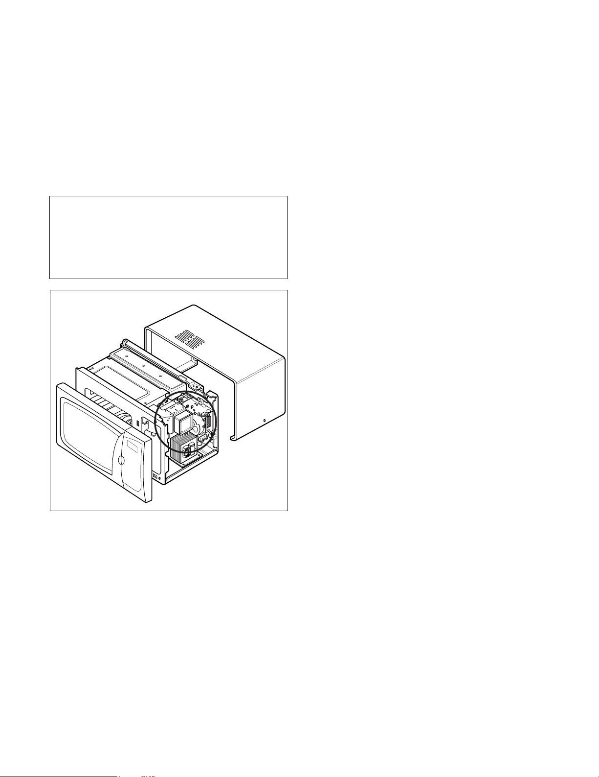
MEASUREMENT WITH OUTER CASE
REMOVED
¥ When you replace the magnetron, measure for
microwave energy leakage before the outer case is
installed and after all necessary components are
replaced or adjusted.
Special care should be taken in measuring the
following parts. (Circled area of below Fig.)
- Around the magnetron
- The waveguide
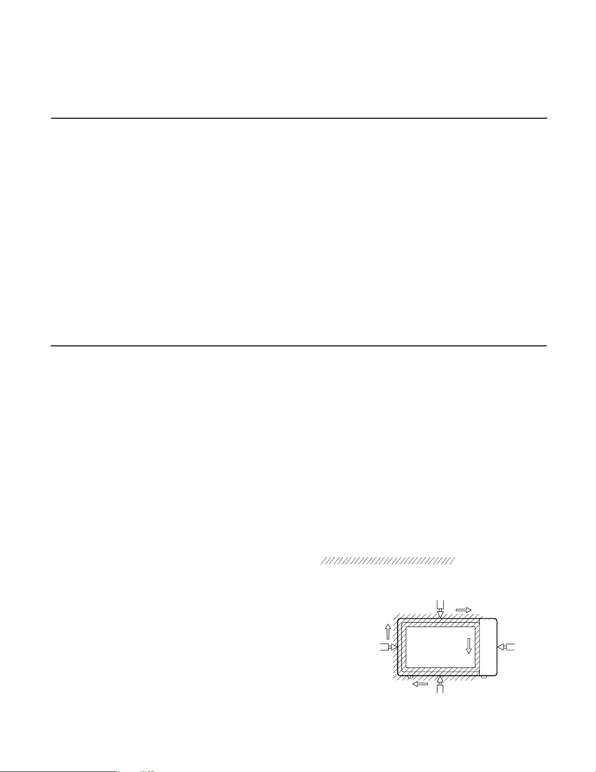
MEASUREMENT WITH A FULLY
ASSEMBLED OVEN
¥ After all components, including the outer case, are fully
assembled, measure for microwave energy leakage
around the door viewing window, the exhaust opening,
and air inlet openings.
¥ Microwave energy leakage must not exceed the values
prescribed below.
NOTE: Leakage with the outer case removedless than
5 mW/cm.sq. Leakage for a fully assembled
oven (Before the latch switch (primary) is
interrupted) with the door in a slightly opened
position-less than 2 mW/cm.sq.
NOTES WHEN MEASURING
¥ Do not exceed meter full scale deflection.
¥ The test probe must be removed no faster than
1 inch/sec (2.5 cm/sec) along the shaded area,
otherwise a false reading may result.
¥ The test probe must be held with the grip portion of the
handle.
A false reading may result if the operator's hand is
between the handle and the probe.
¥ When testing near a corner of the door, keep the probe
perpendicular to the surface making sure the probe
horizontally along the oven surface, this may possibly
cause probe damage.
RECORD KEEPING AND NOTIFICATION
AFTER MEASUREMENT
¥ After adjustment and repair of any microwave energy
interruption or microwave energy blocking device,
record the measured values for future reference. Also
enter the information on the service invoice.
¥ The microwave energy leakage should not be more
than 4 mW/cm.sq. after determining that all parts are in
good condition, functioning properly and genuine
replacement parts which are listed in this manual have
been used.
¥ At least once a year, have the electromagnetic energy
leakage monitor checked for calibration by its
manufacturer.
WARNING : AVOID CONTACTING ANY
HIGH VOLTAGE PARTS
(Magnetron, H.V. Transformer,
H.V. Capacitor, H.V. Cable AssÕy,
H.V. Circuit Protector)
5-3
¥ Microwave power output measurement is made with
the microwave oven supplied at its rated voltage and
operated at its maximum microwave power setting with
a load of (1000±5) g of potable water.
¥ The water is contained in a cylindrical borosilicate glass
vessel having a maximum material thickness of 3 mm
and an outside diameter of approximately 190mm.
¥ The oven and the empty vessel are at ambient
temperature prior to the start of the test.
¥ The initial temperature (T1) of the water is (10±2)¡C It
is measured immediately before the water is added to
the vessel. After addition of the water to the vessel,
the load is immediately placed on the center of the
turntable which is in the lowest position and the
microwave power switched on.
¥ The time T for the temperature of the water to rise by a
value Æ T of (10±2)¡K is measured, where T is the time
in seconds and ÆT is the temperature rise. The initial
and final water temperatures are selected so that the
maximum difference between the final water
temperature and the ambient temperature is 5¡K.
¥ The microwave power output P in watts is calculated
from the following formula :
is measured while the microwave generator is
operating at full power. Magnetron filament heat-up
time is not included. (about 3 sec)
¥ The water is stirred to equalize temperature throughout
the vessel, prior to measuring the final water
temperature.
¥ Stirring devices and measuring instruments are
selected in order to minimize addition or removal of
heat.
WATER LOAD
TURNTABLE
MEASUREMENT OF MICROWAVE POWER OUTPUT
P =
DISASSEMBLY AND ADJUSTMENT
A. OUTER CASE REMOVAL
1) Disconnect the power supply cord from the outlet.
2) Remove the screws from the rear and along side
edges of the case.
The outer case must be moved backward to be lifted
off.
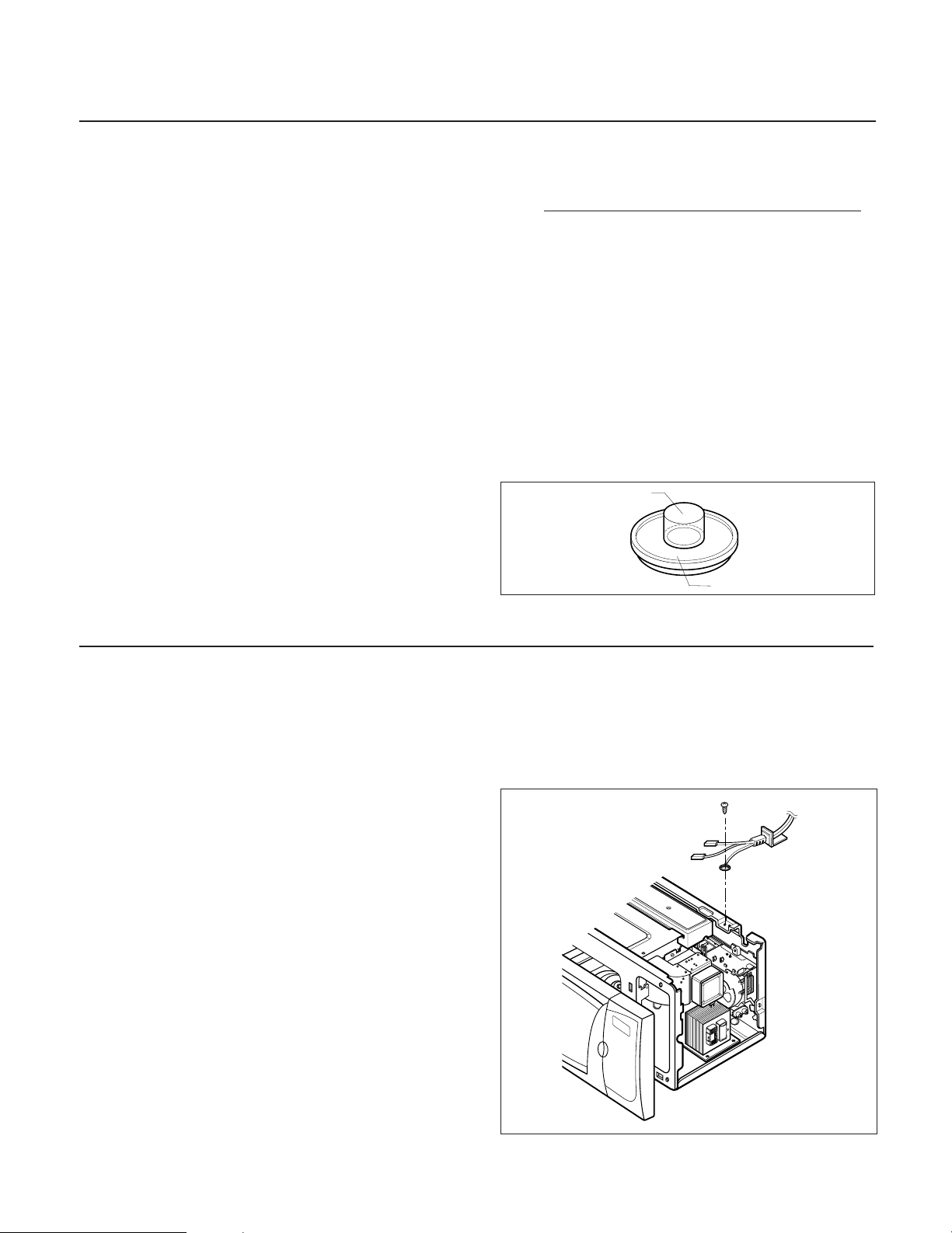
B. POWER SUPPLY CORD
1) Remove the outer case.
2) Disconnect two terminals, and remove one screw of
the earth terminal.
CAUTION: DISCHARGE THE HIGH VOLTAGE
CAPACITOR BEFORE SERVICING
(refer to page 2-1)
C. CONTROL PANEL ASSEMBLY
1) Disconnect the leadwire from the PCB SUB ASSÕY.
2) Remove the screws for the earth and securing the
control panel.
3) Lift control panel ASSÕY from the oven by the tab
unhooked.
4187 X (DT) + 0.88 X (T2 - T0) X M
T
¥ T2: Temperature after heating
¥ T0: Temperature after bowl
¥ M: Weight of bowl
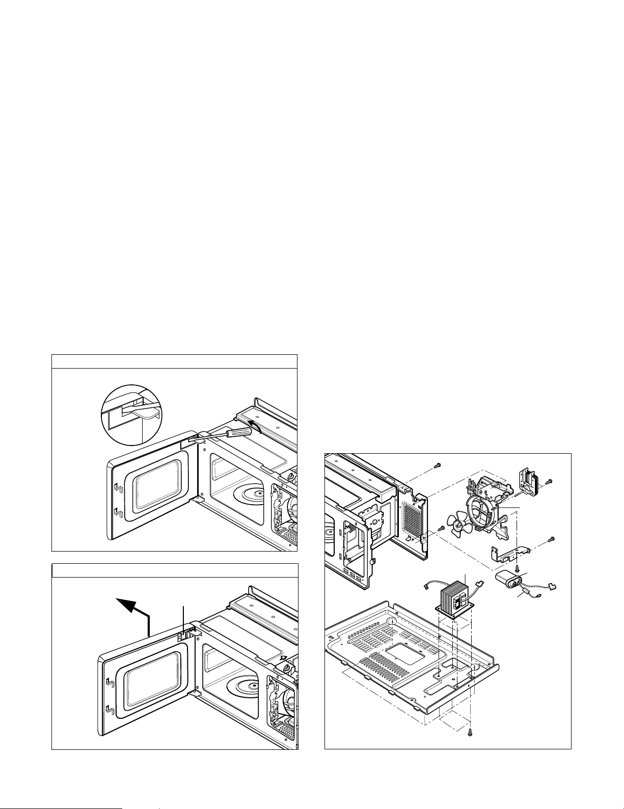
D. DOOR GROSS ASSEMBLY REMOVAL
1) Open the door.
2) Remove the choke cover cap very carefully with a
flat-blade screwdriver.
CAUTION : Be careful not to damage door seal plate
by screwdriver.
3) Lift up and push the door.
NOTE:
1. After replacing the door, be sure to check that the
primary switch, monitor switch, and secondary switch
operate normally.
2. After replacing the door, check for microwave energy
leakage with a survey meter. Microwave energy must
be below the limit of 5 mW/cm. (with a 275 ml water
load)
3. When mounting the door assembly to the oven
assembly, be sure to adjust the door assembly parallel
to the chassis. Also adjust so the door has no play
between the inner door surface and oven frame
assembly. If the door assembly is not mounted
properly, microwaves may leak from the clearance
between the door and the oven.
E. HIGH VOLTAGE TRANSFORMER
REMOVAL
1) Discharge the high voltage capacitor.
2) Disconnect the leadwire from magnetron, high voltage
transformer, and capacitor.
3) Remove the screw holding the high voltage
transformer to the baseplate.
F. FAN MOTOR ASSEMBLY REMOVAL
1) Discharge the high voltage capacitor.
2) Disconnect the leadwire from fan motor, noise filter
and high voltage capacitor.
3) Remove the two screws holding the the suction guide
ASSÕY to the oven cavity and remove the high voltage
diode earth screw.
4) Remove the screw of the capacitor bracket.
5) Remove the two screws holding the fan motor ASSÕY
to the suction guide ASSÕY.
G. HIGH VOLTAGE CAPACITOR AND
DIODE REMOVAL
1) Discharge the high voltage capacitor.
2) Disconnect the leadwire from fan motor, noise filter
and high voltage capacitor.
3) Remove the screw holding the suction guide ASSÕY to
the oven cavity and remove the high voltage diode
earth screw.
4) Remove the screw holding the high voltage capacitor
bracket.
Remove choke cover cap
Remove door
H.V.
Transformer
H.V.
Diode
H.V.
Capacitor
Suction
Guide
Fan Motor ASS'Y
5-4
Door seal plate
5-5
H. AIR DUCT ASSEMBLY REMOVAL
1) Disconnect the leadwire from lamp.
2) Remove the mounting screw to Latch Board.
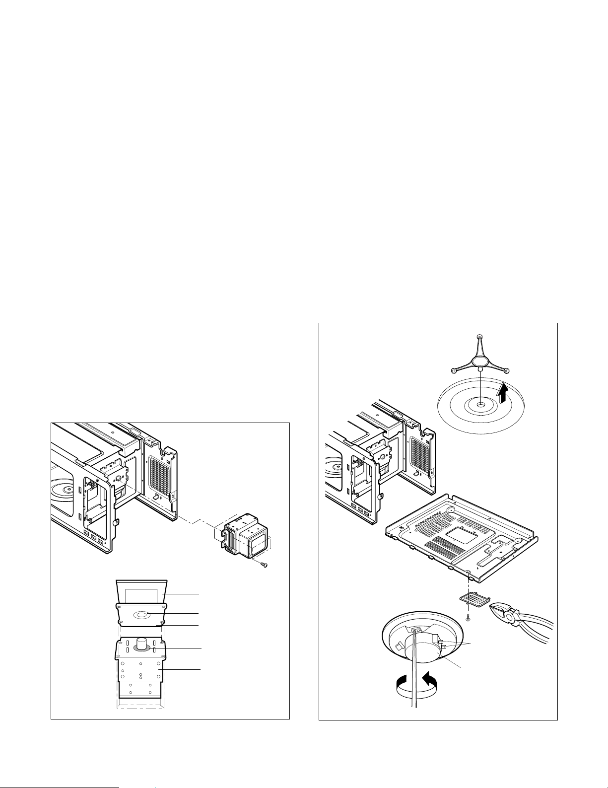
I. MAGNETRON REMOVAL
1) Disconnect the leadwire from the high voltage
transformer and high voltage capacitor.
2) Carefully remove the mounting screws holding the
magnetron and the waveguide.
3) Remove the magnetron ASSÕY until the tube is
clear from the waveguide.
NOTE:
1. When removing the magnetron, make sure its
dome does not hit any adjacent parts, or it may be
damaged.
2. When replacing the magnetron, be sure to install
the magnetron gasket in the correct position and
be sure that the gasket is in good condition.
3. After replacing the magnetron, check for microwave
leakage with a survey meter around the
magnetron. Microwave energy must be below the
limit of 5 mW/cm2. (With a 275 ml. water load).
Make sure that gasket is rigidly attached to the
magnetron. To prevent microwave leakage,
tighten the mounting screws properly, making sure
there is no gap between the waveguide and the
magnetron.
J. REMOVING THE TURNTABLE MOTOR
1) Remove the turntable.
2) Remove the Rotating Ring.
3) Lay the unit down on its back.
4) Remove the turntable motor cover.
The turntable base cover is easily removed by
pinching the six parts with a wire cutting.
5) Disconnect the leadwire from the turntable motor
terminals.
6) Remove the screw securing the turntable motor to
the oven cavity ASSÕY
7) After repairing the motor, rotate the removed
turntable motor cover.
8) Fit the turntable motor coverÕs projecting part to the
base plate slit.
NOTE:
1. Remove the wire lead from the turntable motor
VERY CAREFULLY.
2. Be sure to grasp the connector, not the wires, when
removing.
Waveguide
Magnetron
Magnetron
Gasket
Magnetron
Dome
Waveguide
Bracket
Wire Leads
Turntable Motor
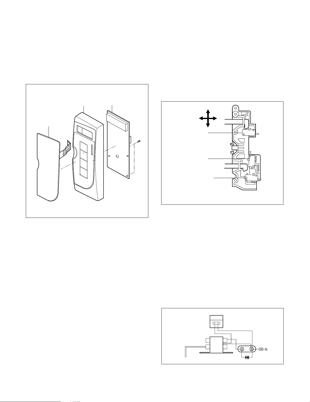
K. PCB ASSEMBLY REMOVAL
1) Remove the control panel assembly from the
cavity. (Refer to control panel assembly removal
on previous page.)
2) Remove screws which hold the PCB SUB ASSÕY to
the control panel.
3) Disconnect the flat cable from the PCB SUB
ASSÕY and take off the PCB SUB ASSÕY.
L. INTERLOCK SYSTEM
1) INTERLOCK MECHANISM
The door lock mechanism is a device which has
been specially designed to eliminate completely
microwave activity when the door is opened during
cooking and thus to prevent the danger resulting
from the microwave leakage.
2) MOUNTING OF THE PRIMARY/MONITOR/
SECONDARY SWITCHES TO THE LATCH
BOARD
3) INSTALLATION AND ADJUSTMENT OF THE
LATCH BOARD TO THE OVEN ASSEMBLY
¥ Mount the latch board to the oven assembly.
¥ Adjust the latch board in the arrow direction so that
oven door will not have any play in it when the door
is closed.
¥ Tighten the mounting screw.
¥ Check for play in the door by pushing the door
release button. Door movement should be less
than 0.5 mm. (1/64 inch)
Don't push the door release button while making
adjustment. Make sure that the latch moves
smoothly after adjustment are completed and that
the screws are tight. Make sure the primary, monitor,
and secondary switches operate properly by
following the continuity test procedure.
5-6
Key Membrane
Control Panel
PCB Sub ASS'Y
FIG. 1
ADJUSTMENT
DIRECTION
PRIMARY
SWITCH
MONITOR
SWITCH
SECONDARY
SWITCH
CAUTION: CHECK THE CORRECT POSITION
MAGNETRON
H.V. TRANSFORMER
H.V. CAPACITOR
PRIMARY
CIRCUIT PROTECTOR
H.V.
DIODE
A. PRIMARY INTERLOCK SWITCH TEST
When the door release button is depressed slowly
with the door closed, an audible click should be
heard at the same time or successively at
intervals. When the button is released slowly, the
latches should activate the switches with an
audible click.
If the latches do not activate the switches when
the door is closed, the switches should be a
adjusted in accordance with the adjustment
procedure. Disconnect the wire lead from the
primary switch. Connect the ohmmeter leads to
the common (COM) and normally open (NO)
terminal of the switch. The meter should indicate
an open circuit in the door open condition.
When the door is closed, the meter should
indicate a closed circuit.
When the primary switch operation is abnormal,
make the necessary adjustment or replace the
switch only with the same type of switch.
B. SECONDARY INTERLOCK SWITCH TEST
Disconnect the wire lead from the secondary
switch.
Connect the ohmmeter leads to the common
(COM) and normally open (NO) terminals of the
switch. The meter should indicate a open circuit in
the door open condition. When the door is closed,
meter should indicate an closed circuit. When the
secondary switch operation is abnormal, make the
necessary adjustment or replace the switch only
with the same type of switch.
C. MONITOR SWITCH TEST
Disconnect the wire lead from the monitor switch.
Connect the ohmmeter leads to the common
(COM) and normally closed (NC) terminals of the
switch. The meter should indicate closed circuit in
the door open condition. When the door is closed,
meter should indicate an open circuit. When the
monitor switch operation is abnormal, replace with
the same type of switch.
NOTE: After repairing the door or the interlock
system, it is necessary to do this continuity
test before operating the oven.
5-7
WARNING : FOR CONTINUED PROTECTION AGAINST EXCESSIVE RADIATION
EMISSION, REPLACE ONLY WITH IDENTICAL REPLACEMENT PARTS.
TYPE NO. SZM-V 16-FA-63 OR VP-533A-OF FOR PRIMARY SWITCH
TYPE NO. SZM-V 16-FA-62 OR VP-532A-OF FOR MONITOR SWITCH
TYPE NO. SZM-V 16-FA-63 OR VP-533A-OF FOR SECONDARY SWITCH
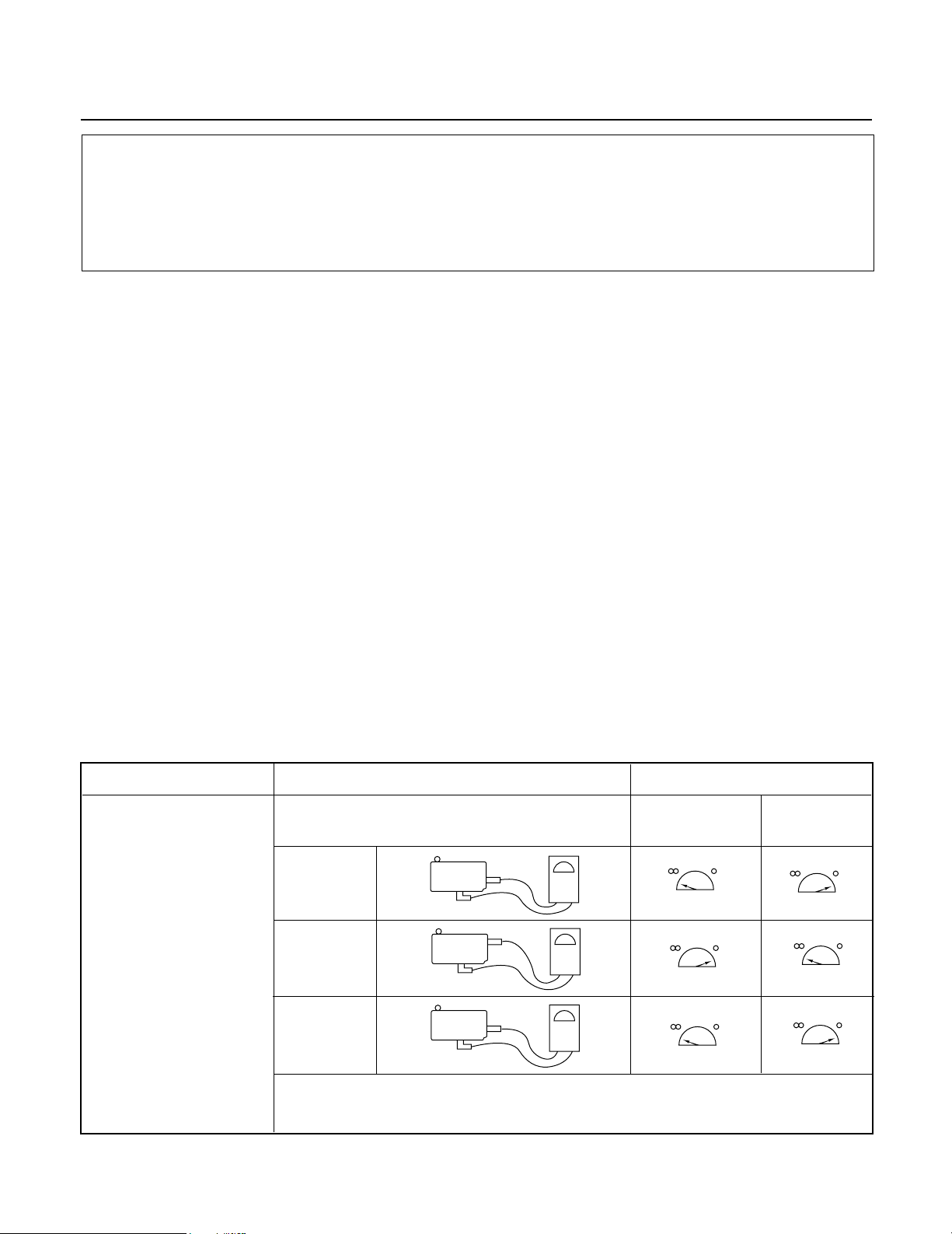
COMPONENTS TEST PROCEDURE RESULTS
SWITCHES Check for continuity of the Door Door
(Wire leads removed) switch with an Ohm-meter open closed
Primary
Switch
Monitor
Switch
NOTE : After checking for the continuity of switches, make sure that are
connected correctly.
INTERLOCK CONTINUITY TEST
Secondary
Switch
COM
COM
COM
NO
NC
NO
 Loading...