

LG 47LZ9600-TA, 55LW9500-TA, 55LZ9600-TA, 47LW9500-TA, 47LW7700-TA Owner's Manual
...
OWNER'S MANUAL
SPECIFICATION
PIC COS
Chatchai A. Chaiyasith E.
1.Model Description
Part No.
MFL67213501
MODEL
LCD BRAND
LG
(1104 REV00)
SUFFIX
EXPORT Product Name
Y11 GP3
2.Printing Specification
1.Trim Size (Format)
Trim Size : 182 mm x 257 mm
2.Printing Colors
* Cover :
1 Color :CMYK
* Inside :
1 Color : CMYK
3.Stock (Paper)
* Cover :
1 Color : White Wood free 80 gramm
* Stock :
1 Color : White Wood free 80 gramm
4.Printing Method :
Off-Set
5.Bindery :
Stiching
6.Laguage :
ENGLISH
7.Number of pages :
52 pages
Note
“This part contain Eco-hazardous substances (Pb, Cd, Hg, Cr6+, PBB, PBDE, etc.) within LG standard level,
Details should be followed Eco-SCM management standard[LG(56)-A-2524].
Especially, Part should be followed and controlled the following specification .
(1)Eco-hazardous substances test report should be submitted
when Part certification test and First Mass Production.
(2) Especially, Don’t use or contain lead(Pb) and cadmium(Cd) in ink.
3. Special information
4. Change
10
9
8
7
6
5
4
3
2
1
Rev.No.
DD/MM/YY Signature Change No.
Change Content
Cover front Page 2. Page 3. Page 50. Page 51. Cover rear
Total 52 page = Cover front + 50 body + Cover rear

P/NO : MFL67213501 (1104-REV00)
Printed in Thailand
www.lg.com
OWNER’S MANUAL
LED LCD TV
Please read this manual carefully before operating your
set and retain it for future reference.
SAFETY INSTRUCIONS
2
ENG
ENGLISH
Please read these safety precautions carefully before using the product.
In this manual, the illustration may be somewhat different from your product because it is
just example to help the instruction.
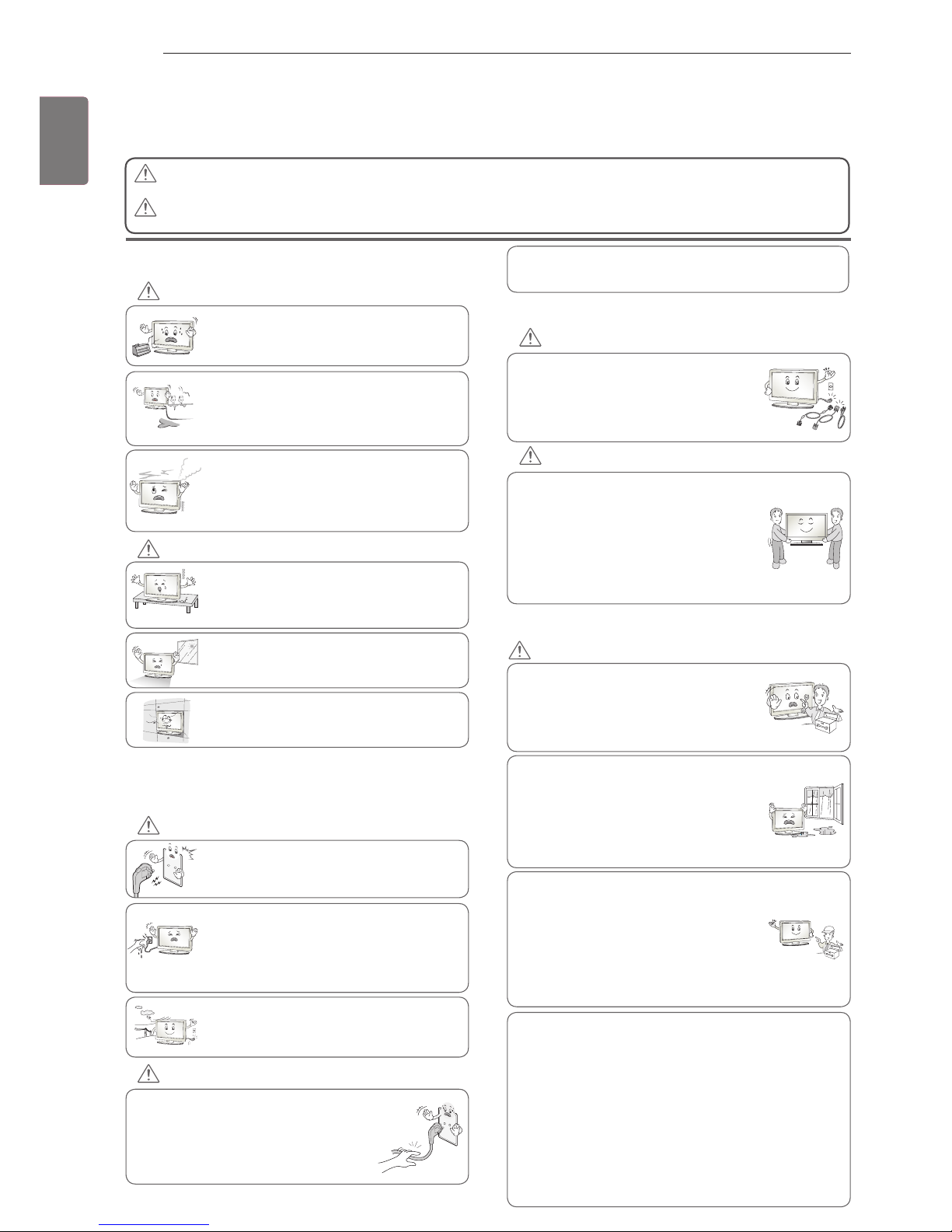
PRECAUTION IN INSTALLING THE PRODUCT
Keep away from heat sources like electrical
heaters.
- Electrical shock, fire, malfunction or
deformation may occur.
If you can smell smoke or other odours or hear
a strange sound unplug the power cord and
contact the service center.
- If you continue to use without taking proper
measures, electrical shock or fire can occur.
Do not use the product in damp place such
as a bathroom or any place where it is likely
to get wet.
- This may cause a fire or could give an
electric shock.
Install the product on a flat and stable place
that has no risk of dropping the product.
- If the product is dropped, you may be injured
or the product may be broken.
Keep the product away from direct sunlight.
- The product can be damaged.
Do not place the product in a built-in
installation such as bookcase or rack.
- Ventilation required.
ELECTRICAL POWER RELATED
PRECAUTIONS
Make sure to connect the power cable to a
properly earthed outlet.
- You may be electrocuted or injured.
Do not touch the power plug with wet hands.
Additionally, it the cord pin is wet or covered
with dust, dry the power plug completely or wipe
dust off.
- You may be electrocuted due to excess
moisture.
During a thunder or lightning storm, unplug the
power cable or signal cable.
- You may be electrocuted or a fire can break
out.
Protect the power cord from physical or
mechanical abuse, such as being twisted,
kinked, pinched, closed in a door, or walked
upon. Pay particular attention to plugs, wall
outlets, and the point where the cord exits
the appliance.
PRECAUTIONS WHEN MOVING THE PRODUCT
Do not impact the product when moving it.
- You may be electrocuted or the product
can be damaged.
Make the panel face forward and hold it
with both hands to move.
- If you drop the product, the damaged
product can cause electric shock or fire.
Contact your nearest service center for
repair.
Make sure to turn off the product.
Make sure to remove all cables before
moving the product.
- You may be electrocuted or the product
can be damaged.
PRECAUTIONS WHEN USING THE PRODUCT
Do not disassemble, repair or modify the
product at your own discretion.
- Fire or electric shock accident can occur.
- Contact the service center for check,
calibration or repair.
To reduce the risk of fire or electric shock,
do not expose this apparatus to rain or
moisture.
Apparatus shall not be exposed to
dripping or splashing and no objects
filled with liquids, such as vases, shall be
placed on the apparatus.
Refer all servicing to qualified service
personnel. Servicing is required when
the apparatus has been damaged in any
way, such as power supply cord or plug
is damaged, liquid has been spilled or
objects have fallen into the apparatus, the
apparatus has been exposed to rain or
moisture, does not operate normally, or
has been dropped.
IMPORTANT INFORMATION TO PREVENT “IMAGE BURN /
BURN-IN” ON YOUR TELEVISION SCREEN
-
When a fixed image (e.g. logos, screen menus, video game,
computer display or teletext pages) is displayed on the
television for an extended period it can become permanently
imprinted on the screen. This phenomenon is known as “image
burn” or “burn-in”. Image burn is not covered under the
manufacturer’s warranty.
-
In order to prevent image burn, avoid displaying a fixed
image on your television’s screen for a prolonged period (2 or
more hours for LCD, 1 or more hours for Plasma).
-
Image burn can also occur on the letterboxed areas of
your television if you use the 4:3 aspect ratio setting for an
extended period.
As long as this unit is connected to the AC wall outlet, it is
not disconnected from the AC power source even if you
turn off this unit by SWITCH.
If you ignore the warning message, you may be seriously injured or there is a
possibility of accident or death.
If you ignore the caution message, you may be slightly injured or the product may
be damaged.
CAUTION
WARNING
WARNING
CAUTION
WARNING
CAUTION
WARNING
CAUTION
WARNING
3
ENG
ENGLISH
ASSEMBLING AND PREPARING
ASSEMBLING AND PREPARING
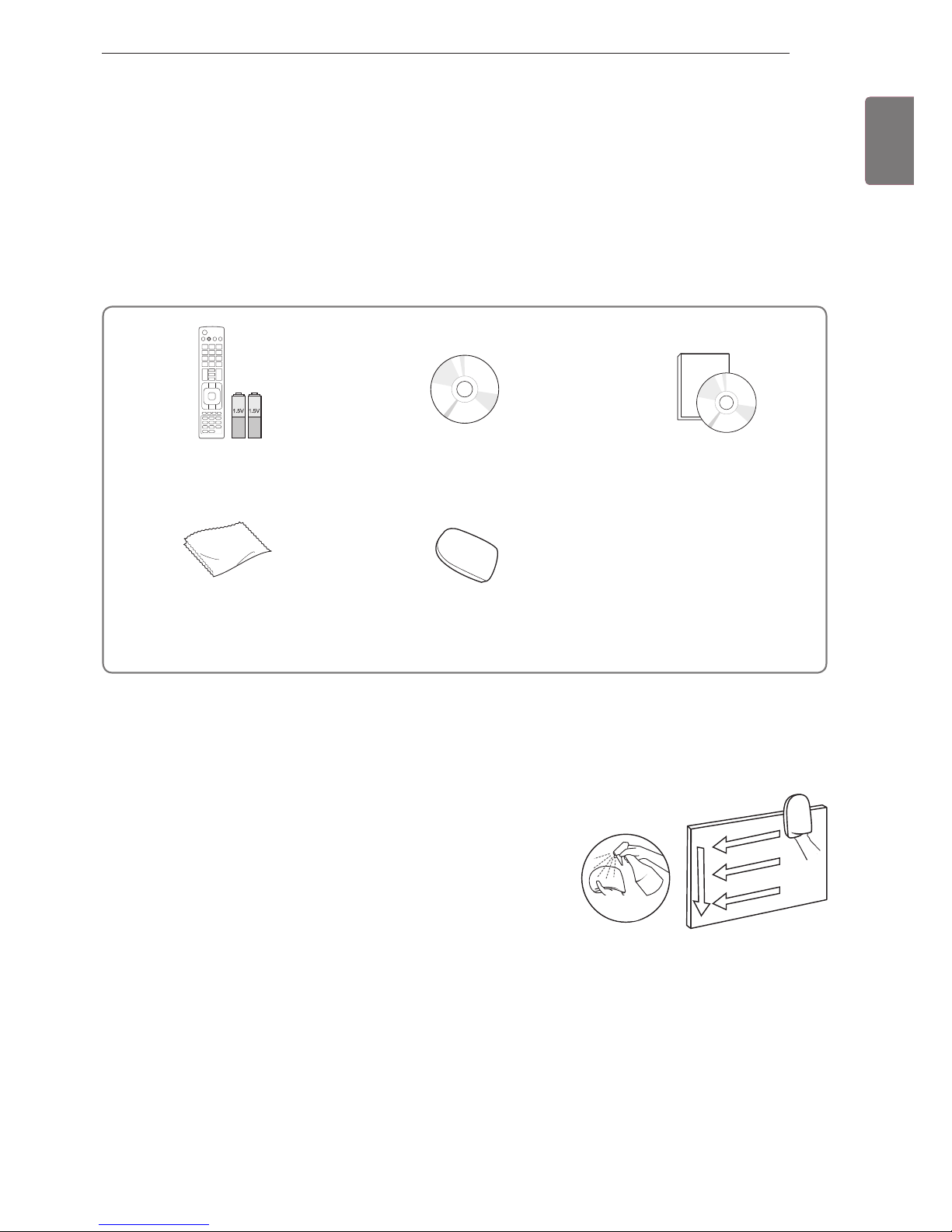
Unpacking
Remote control and batteries
(AAA)
Nero MediaHome 4 Essentials CD
Owner’s manual
Polishing cloth1
(Depending on model)
Cleansing Cloths (Mitt)
2
(Depending on model)
Check your product box for the following items. If there are any missing accessories, contact the local
dealer where you purchased your product.
The illustrations in this manual may differ from the actual product and item.
1 Gently wipe the spots on the cabinet with the polishing cloth.
Water
2 Wipe spots on the exterior only with the cleansing cloths.
Do not wipe roughly when removing stains. Excessive pressure
may cause scratches or discolouration.
For cleaning front frame, please slowly wipe in one direction
after spraying water 1-2 times on cleansing cloths. Please
remove excessive moisture after cleaning. Excessive moisture
may cause water stains on the frame.
4
ENG
ENGLISH
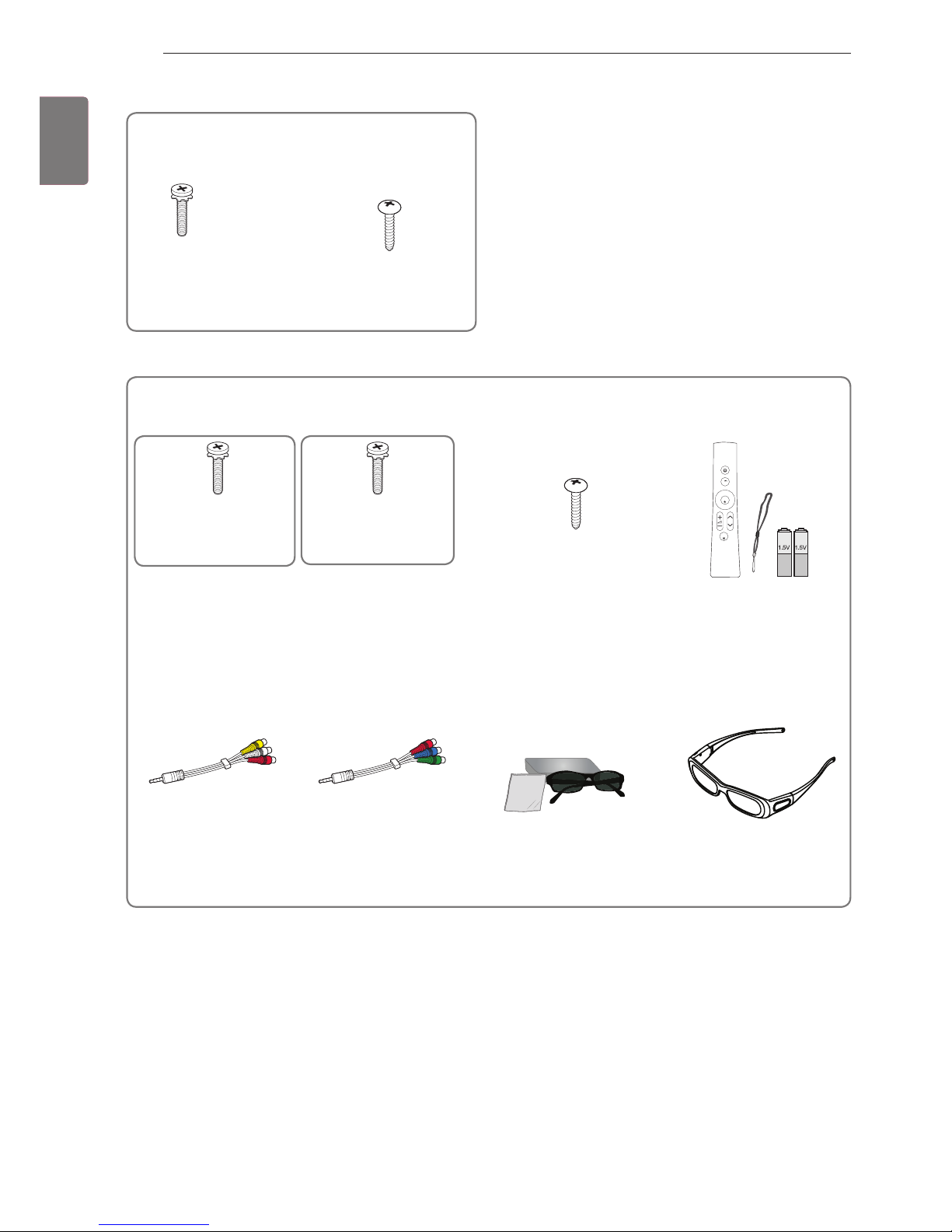
ASSEMBLING AND PREPARING
Only 32/37/42/47/55LV55**, 42/47/55LW57**, 42/47/55/65LW65**, 47/55LW77**, 47/55LW95
**
Screw for assembly Screw for fixing
(Only 32/37LV55**)
Magic Motion Remote
Control,
Strap, Batteries (AA)
(Only 47/55LW77**,
47/55LW95**)
Composite gender cable Component gender cable 3D Glasses1
(AG-P110, AG-F110)
(Only 42/47/55LW57**,
42/47/55/65LW65**)
3D Glasses (AG-S250)
(Only 47/55LW77**,
47/55LW95**)
x 8
M4 x 16
x 8
M4 x 12
(Except for
47/55LW95**)
Home
OK
P
MUTE
Only 32/37/42/47/55LV37
**
Screw for assembly Screw for fixing
(Only 32/37LV37**)
M4 x 12
x 8
(Only 47/55LW95**)
1 The number of 3D glasses may differ depending on the country.

5
ENG
ENGLISH
ASSEMBLING AND PREPARING
Only 47/55LZ96
**
x 4
x 6
x 6
Home
OK
P
MUTE
M3 x 6
M4 x 7 M4 x 14
Bolts for stand and wall mounting bracket assembly
Magic Motion Remote
Control,
Strap, Batteries (AA)
Composite gender cable Component gender cable
3D Glasses (AG-S250)
Cable holder
Stand Base Stand Body Stand Rear Cover Display Link Cable Cover
Display Link Cable
(stand type and wall
mounting type)
Wall Mounting Bracket
(one for the set and one for
the wall)
Wall Mounting Bracket
Pushpin
Set Protection Bracket
Wall Anchor Screw
x 2
x 2
x 2
x 2
6
ENG
ENGLISH
ASSEMBLING AND PREPARING
Additional information
Viewing the owner’s manual
The owner’s manual in PDF file format is supplied on the enclosed CD. Install the Adobe Acrobat Reader to
view the owner’s manual on your PC.
1
Insert the supplied CD.
The web page appears automatically.
2
Click Owner’s Manual on the web page.
3
View the owner’s manual.
If the web page does not appear automatically, access My computer and then click LG and
index.
html
to view the owner’s manual.
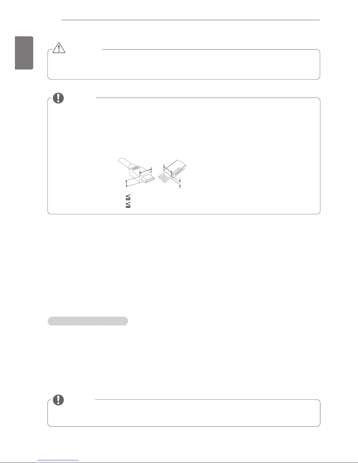
NOTE
For an optimal connection, HDMI cables and USB devices should have bezels less than 10 mm thick
and 18 mm width. (Depending on model)
B
A
A
B
*A 10 mm
*B 18 mm
The items supplied with your product may vary depending on the model.
Product specifications or contents of this manual may be changed without prior notice due to upgrade
of product functions.
NOTE
Do not use any unapproved items to ensure the safety and product life span.
Any damages or injuries by using unapproved items are not covered by the warranty.
CAUTION
7
ENG
ENGLISH
ASSEMBLING AND PREPARING
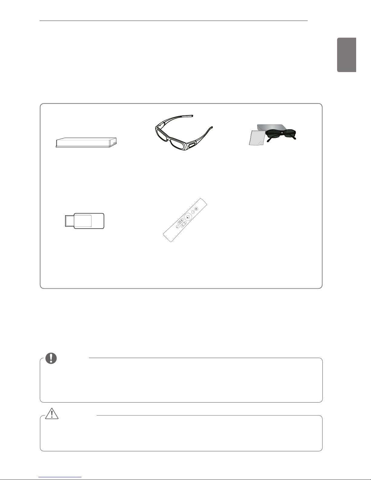
Separate purchase
Separate purchase items can be changed or modified for quality improvement without any notification.
Contact your dealer for buying these items.
These devices only work with compatible LG LED LCD TV.
Wireless Media Box
(AN-WL100W)
(Except for 32/37/42/47/55LV37**)
3D Glasses
(AG-S230, AG-S250, AG-S270)
(Only 47/55LW77**, 47/55LW95**,
47/55LZ96**)
3D Glasses
(AG-P110, AG-F110)
(Only 42/47/55LW57**,
42/47/55/65LW65**)
Wireless LAN for Broadband
/DLNA Adaptor
(AN-WF100)
(Except for 47/55LW95**)
Magic Motion Remote Control
(AN-MR200)
Home
OK
P
MUTE
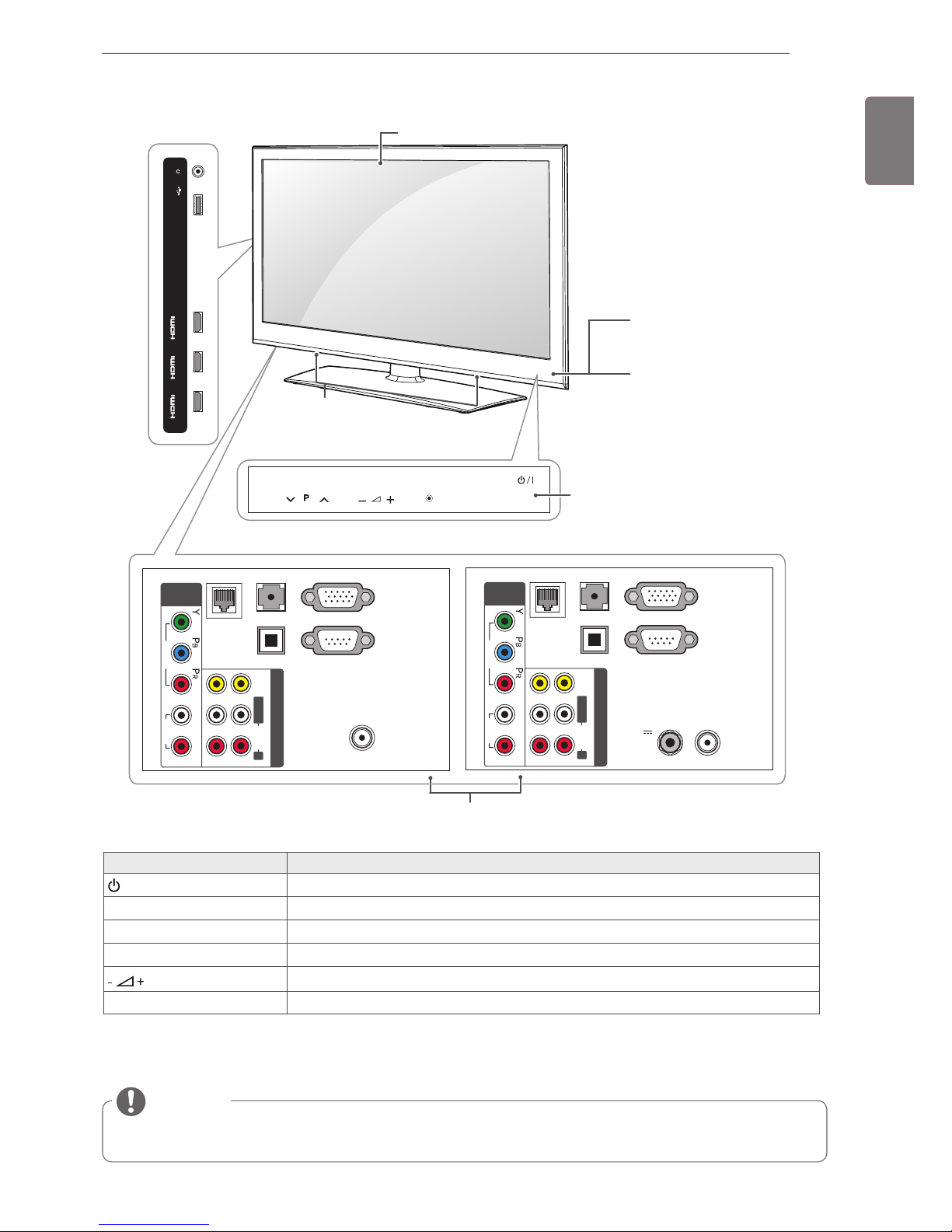
Parts and buttons
Image shown may differ from your TV.
TV can be placed in standby mode in order to reduce the power consumption. And TV should be
turned off if it will not be watched for some time, as this will reduce energy consumption.
The energy consumed during use can be significantly reduced if the level of brightness of the picture
is reduced, and this will reduce the overall running cost.
NOTE
Do not step on the glass stand or subject it to any impact. It may break, causing possible injury from
fragments of glass, or the TV may fall.
Do not drag the TV. The floor or the product may be damaged.
CAUTION

8
ENG
ENGLISH
ASSEMBLING AND PREPARING
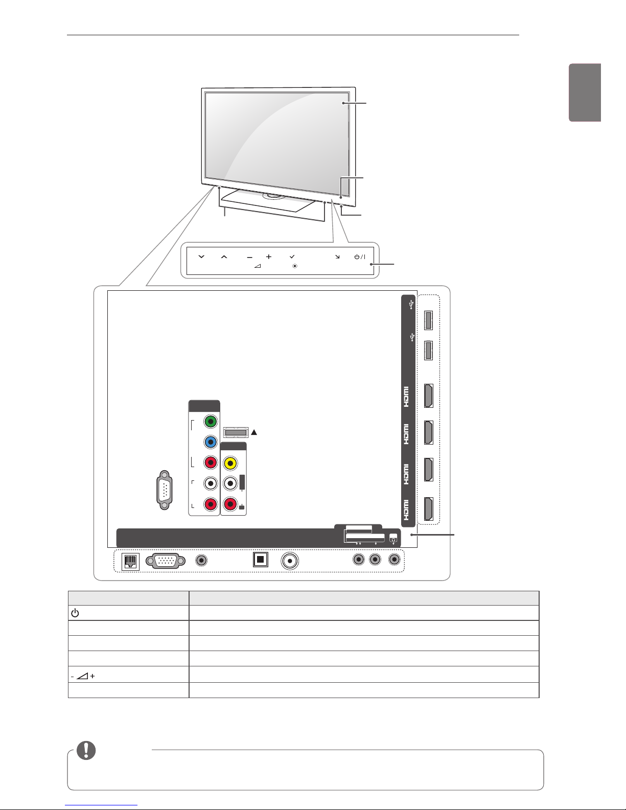
Only 42/47/55/65LW65
**,
47/55LW95
**
1 Intelligent sensor - Adjusts the image quality and brightness based on the surrounding environment.
2 All of the buttons are touch sensitive and can be operated through simple touch with your finger.
RS-232C IN (CONTROL&SERVICE)
IN 1(ARC) IN 2IN 3IN 4
LAN
RGB IN (PC)
OPTICAL DIGITAL
AUDIO OUT
AUDIO IN
(RGB/DVI)
ANTENNA/
CABLE IN
AV IN 2
AUDIO / VIDEO
COMPONENT IN 2
AUDIO / Y PB P
R
H/P
WIRELESS
CONTROL
AUDIO
VIDEO
L/MONO
R
AV IN 1
COMPONENT
IN 1
AUDIO
RL
Y
P
B
P
R
VIDEO
/DVI /DVI /DVI /DVI
HDD IN
USB IN 1
USB Apps
USB IN 2
INPUT
HOME
P
OK
H
INPUT
HOME
H
OK
P
Touch
buttons
2
Rear Connection panel
Touch button
2
Description
/
I
Turns the power on or off.
INPUT Changes the input source.
HOME Accesses the Home menu, or saves your input and exits the menus.
OK
ꔉ
Selects the highlighted menu option or confirms an input.
Adjusts the volume level.
v
P
^
Scrolls through the saved programmes.
Speakers
NOTE
You can set the power indicator light to on or off by selecting OPTION in the Home menu - SETUP.
Remote control and intelligent1 sensors
Power indicator
Only 47/55LW95
**
Screen
Only 42/47/55/65LW65
**
9
ENG
ENGLISH
ASSEMBLING AND PREPARING
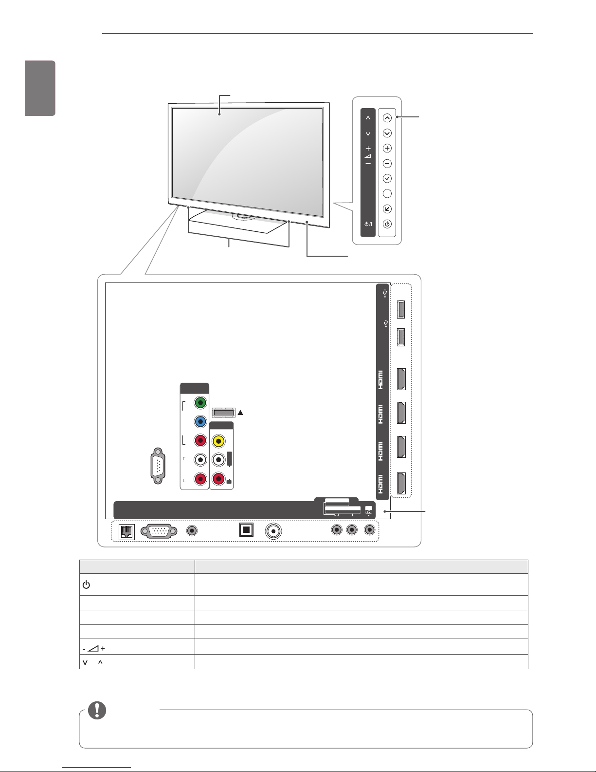
Only 32/37/42/4755LV55
**
1 Intelligent sensor - Adjusts the image quality and brightness based on the surrounding environment.
2 All of the buttons are touch sensitive and can be operated through simple touch with your finger.
RS-232C IN (CONTROL&SERVICE)
IN 1(ARC) IN 2IN 3IN 4
LAN
RGB IN (PC)
AV IN 2
AUDIO / VIDEO
COMPONENT IN 2
AUDIO / Y PB P
R
H/P
WIRELESS
CONTROL
AUDIO
VIDEO
L/MONO
R
AV IN 1
COMPONENT
IN 1
AUDIO
RL
Y
P
B
P
R
VIDEO
/DVI /DVI /DVI /DVI
HDD IN
USB IN 1
USB Apps
USB IN 2
INPUT
HOME
H
P
OK
OPTICAL DIGITAL
AUDIO OUT
AUDIO IN
(RGB/DVI)
ANTENNA/
CABLE IN
Touch buttons
2
Touch button
2
Description
/
I
Turns the power on or off.
INPUT Changes the input source.
HOME Accesses the Home menu, or saves your input and exits the menus.
OK
ꔉ
Selects the highlighted menu option or confirms an input.
Adjusts the volume level.
v
P
^
Scrolls through the saved programmes.
Screen
Speakers
NOTE
You can set the power indicator light to on or off by selecting OPTION in the Home menu - SETUP.
Rear Connection
panel
Power indicator
Remote control and intelligent1 sensors
10
ENG
ENGLISH
ASSEMBLING AND PREPARING
Only 42/47/55LW57
**,
47/55LW77
**
1 Intelligent sensor - Adjusts the image quality and brightness based on the surrounding environment.
Button Description
/
I
Turns the power on or off.
INPUT Changes the input source.
HOME Accesses the Home menu, or saves your input and exits the menus.
OK
ꔉ
Selects the highlighted menu option or confirms an input.
Adjusts the volume level.
P Scrolls through the saved programmes.
RS-232C IN (CONTROL&SERVICE)
IN 1(ARC) IN 2IN 3IN 4
LAN
RGB IN (PC)
AV IN 2
AUDIO / VIDEO
COMPONENT IN 2
AUDIO / Y PB P
R
H/P
WIRELESS
CONTROL
AUDIO
VIDEO
L/MONO
R
AV IN 1
COMPONENT
IN 1
AUDIO
RL
Y
P
B
P
R
VIDEO
/DVI /DVI /DVI /DVI
OK
P
HOME
INPUT
HDD IN
USB IN 1
USB Apps
USB IN 2
H
OPTICAL DIGITAL
AUDIO OUT
AUDIO IN
(RGB/DVI)
ANTENNA/
CABLE IN
Speakers
Remote control and intelligent1
sensors, Power indicator
Screen
Buttons
NOTE
You can set the power indicator light to on or off by selecting OPTION in the Home menu - SETUP.
Rear Connection panel
11
ENG
ENGLISH
ASSEMBLING AND PREPARING
Only 32/37/42/47/55LV37
**
1 Intelligent sensor - Adjusts the image quality and brightness based on the surrounding environment.
2 All of the buttons are touch sensitive and can be operated through simple touch with your finger.
H/P
IN 1 (ARC)
/DVI
IN 2
/DVI
IN 3
/DVI
USB Apps
USB IN
P
INPUT
HOME
OK
RS-232C IN
(CONTROL & SERVICE)
ANTENNA / CABLE IN
RGB IN (PC)
LAN
VIDEO
AUDIO
LR
COMPONENT
IN
AUDIO IN
(RGB/DVI)
OPTICAL DIGITAL
AUDIO OUT
AV IN
L/MONO R
AUDIO
VIDEO
2 1
RS-232C IN
(CONTROL & SERVICE)
ANTENNA
/ CABLE IN
13/18V
700mA Max
LNB IN
Satellite
RGB IN (PC)
LAN
VIDEO
AUDIO
LR
COMPONENT
IN
AUDIO IN
(RGB/DVI)
OPTICAL DIGITAL
AUDIO OUT
AV IN
L/MONO R
AUDIO
VIDEO
2 1
Remote control and intelligent1 sensors
Power indicator
Touch buttons
2
Rear Connection panel
Touch button
2
Description
/
I
Turns the power on or off.
INPUT Changes the input source.
HOME Accesses the Home menu, or saves your input and exits the menus.
OK
ꔉ
Selects the highlighted menu option or confirms an input.
Adjusts the volume level.
v
P
^
Scrolls through the saved programmes.
Speakers
NOTE
You can set the power indicator light to on or off by selecting OPTION in the Home menu - SETUP.
Screen
Except for 32/42/47LV370S
Only 32/42/47LV370S
12
ENG
ENGLISH
ASSEMBLING AND PREPARING
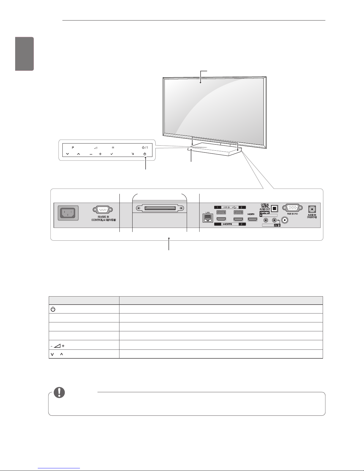
Only 47/55LZ96
**
1 Intelligent sensor - Adjusts the image quality and brightness based on the surrounding environment.
2 All of the buttons are touch sensitive and can be operated through simple touch with your finger.
INPUT
HOME
P
OK
AC IN
USB IN
Y PB P
R
/ AUDIO
VIDEO/AUDIO
AV IN
ANTENNA/CABLE IN
/DVI IN
/DVI
IN3
DISPLAY LINK
HDD IN
USB Apps
1(ARC)
H
Remote control and intel-
ligent1 sensors
Screen
Speakers
Button Description
/
I
Turns the power on or off.
INPUT Changes the input source.
HOME Accesses the Home menu, or saves your input and exits the menus.
OK
ꔉ
Selects the highlighted menu option or confirms an input.
Adjusts the volume level.
P Scrolls through the saved programmes.
NOTE
You can set the power indicator light to on or off by selecting OPTION in the Home menu - SETUP.
Rear Connection panel
Power indicator and
Touch buttons
2
13
ENG
ENGLISH
ASSEMBLING AND PREPARING
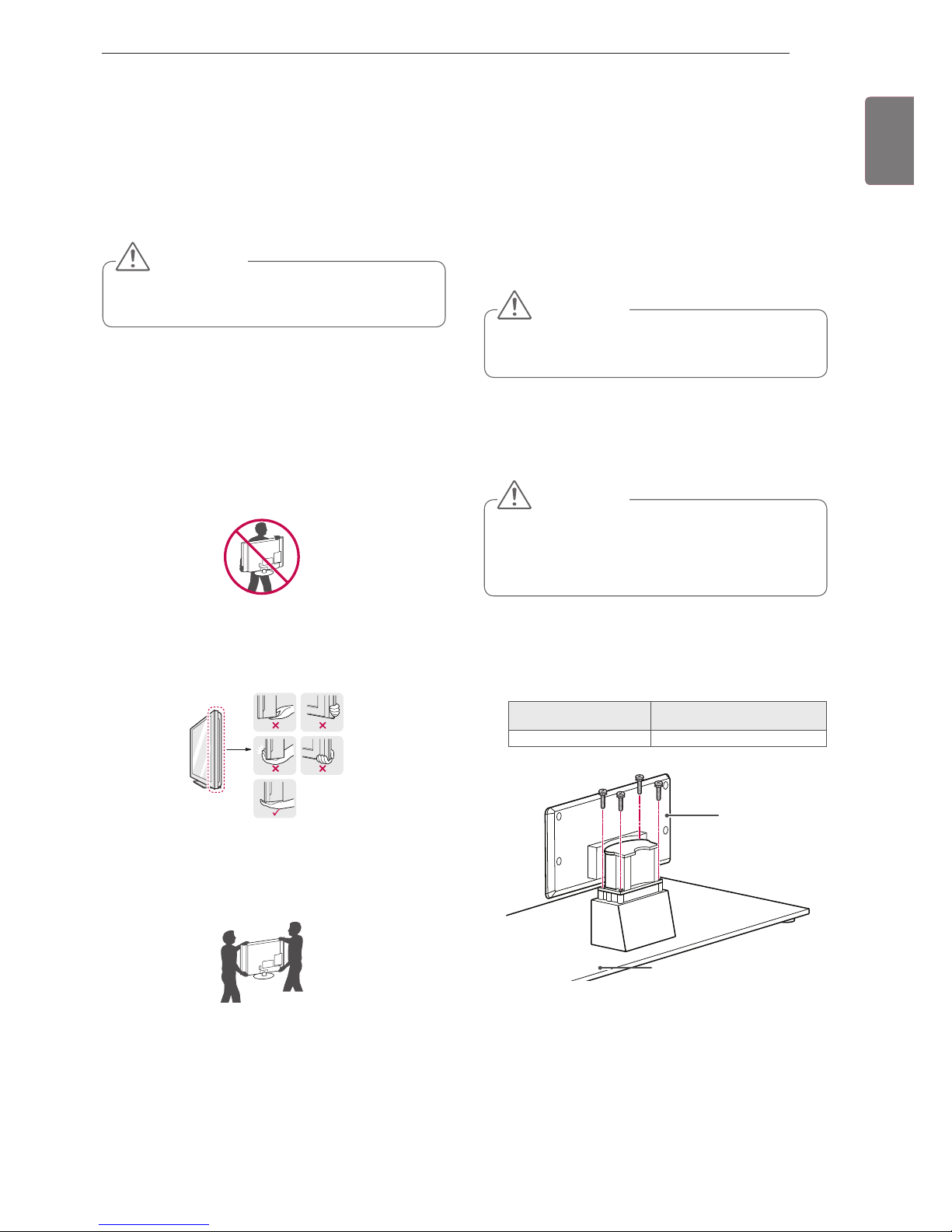
Lifting and moving the TV
When moving or lifting the TV, read the following to
prevent the TV from being scratched or damaged
and for safe transportation regardless of its type
and size.
It is recommended to move the TV in the box
or packing material that the TV originally came
in.
Before moving or lifting the TV, disconnect the
power cord and all cables.
When holding the TV, the screen should face
away from you to avoid damage.
Hold the top and bottom of the TV frame firmly.
Make sure not to hold the transparent part,
speaker, or speaker grill area.
When transporting a large TV, there should be
at least 2 people.
When transporting the TV by hand, hold the
TV as shown in the following illustration.
When transporting the TV, do not expose the
TV to jolts or excessive vibration.
When transporting the TV, keep the TV
upright, never turn the TV on its side or tilt
towards the left or right.
Avoid touching the screen at all times, as this
may result in damage on the screen.
CAUTION
Setting up the TV
Attaching the stand
Only 47/55LW95
**
1
Lay the TV with the screen side down on a flat
surface.
Lay a foam mat or soft protective cloth on the
surface to protect the screen from damage.
Make sure no objects press against the
screen.
CAUTION
2
Assemble the parts of the Stand Body with the
Stand Base of the TV.
Stand Body
Stand Base
Screw for assembly Number of screws
M4 x 16 4
If you are not mounting the TV to a wall, use the
following instructions to attach the stand.
Put your TV on a pedestal stand and mount the TV
on a table or wall.
Tighten the screws firmly to prevent the TV
from tilting forward. Do not over tighten.
CAUTION
14
ENG
ENGLISH
ASSEMBLING AND PREPARING
Only 32/37/42/47/55LV37**,
32/37/42/47/55LV55**, 42/47/55LW57**,
42/47/55/65LW65
**,
47/55LW77
**
1
Lay the TV with the screen side down on a flat
surface.
2
Assemble the parts of the Stand Body with the
Stand Base of the TV.
4 Secure the TV and the stand with the 4 screws.
Screw for assembly Number of screws
M4 x 12 4
Screw for assembly Number of screws
M4 x 12 4
Lay a foam mat or soft protective cloth on the
surface to protect the screen from damage.
Make sure no objects press against the
screen.
CAUTION
4 Secure the TV and the stand with the 4 screws.
3
Assemble the parts of the Stand Rear Cover
with the TV.
Stand Rear Cover
Screw for assembly Number of screws
M4 x 16 4
Stand Base
Stand Body
3
Assemble the TV as shown.
15
ENG
ENGLISH
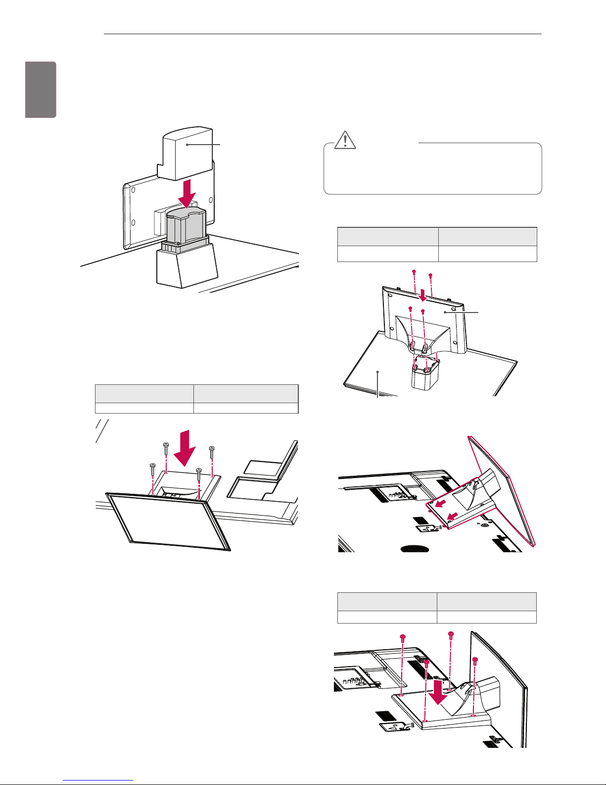
ASSEMBLING AND PREPARING
1
Place the stand base facing down on a table
or flat surface. Assemble the Stand Body with
the Stand Base using the screws provided
with the TV set.
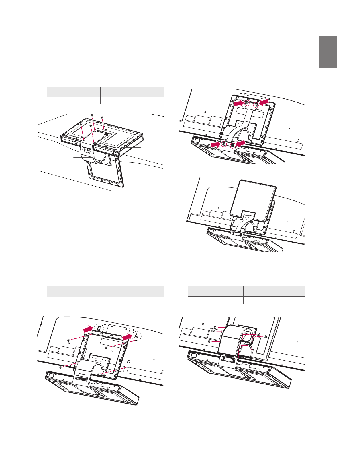
Only 47/55LZ96**
Screw for assembly Number of screws
M4 x 7 4
2
Carefully place the TV screen side down on a
cushioned surface to protect the screen from
damage.
3
Mount the stand to the TV set fitting into
grooves in direction of the arrows as shown in
the figure. Have the TV set align with the holes
for inserting screws. Assemble the Stand Body
with the TV set using the screws provided with
the TV set.
Screw for assembly Number of screws
M4 x 14 4
4
Use the Display Link Cable (for stand; the
shorter one) to connect the Stand Base and
the display link input on the TV. After connection, fasten the screws with a driver to mount
the cable tightly.
5
Place the Stand Rear Cover properly.
6
Place the Display Link Cable Cover and con-
nect it with the Stand Body using the screws
provided with the TV set.
Screw for assembly Number of screws
M3 x 6 4
Stand Body
Stand
Base
 Loading...