

Page 1

OWNER’S MANUAL
MONITOR SIGNAGE
Please read this manual carefully before operating your set and retain it
for future reference.
MONITOR SIGNAGE MODELS
55LV75A
55LV77A
www.lg.com
Page 2

TABLE OF CONTENTS
2
ENGLISH
TABLE OF CONTENTS
ENG
4 LICENSES
5 ASSEMBLING AND
5 Accessories
6 Parts
7 To Install in a Portrait Layout
7 Remove L-brackets before Installation
8 STORAGE METHOD FOR PANEL
8 - Correct Method
8 - Incorrect Method
9 Installing on a Wall
11 EXTERNAL EQUIPMENT SETUP
11 - IR RECEIVER
12 Tiling Displays
12 - How to Mount the Set
13 - How to Join Sets
14 REMOTE CONTROL
PREPARING
PROTECTION
25 ENTERTAINMENT
25 - Connecting to a Wired Network
26 - Network Status
27 - Connecting USB Storage Devices
28 - Browsing Files
30 - Viewing Movies
33 - Viewing Photos
36 - Listening to Music
38 - Viewing the Contents List
39 - DivX® VOD Guide
40 - Using PIP/PBP
41 CUSTOMIZING SETTINGS
41 Accessing the Main Menus
42 - PICTURE Settings
45 - AUDIO Settings
46 - TIME Settings
47 - OPTION Settings
52 Picture ID
53 - NETWORK Settings
16 Displaying the Device Name Connected
to an Input Port
17 USING THE MONITOR SET
17 Connecting to a PC
17 - RGB Connection
18 - DVI Connection
18 - HDMI Connection
19 - Display Port Connection
19 - IR Receiver Connection
20 Adjusting the Screen
20 - Selecting an Image Mode
20 - Customizing Image Options
21 - Customizing PC Display Options
22 Using Additional Options
22 - Adjusting Aspect Ratio
24 - Using the Input List
54 MAKING CONNECTIONS
55 External Device Connection
55 - DVI Connection
55 - HDMI Connection
56 - Component Connection
56 - AV(CVBS) Connection
57 - Audio Connection
57 Connecting to the LAN
57 Connecting to a USB
58 Daisy Chain Monitors
59 - Using the Multi Display Mode function
60 TROUBLESHOOTING
62 SPECIFICATIONS
Page 3

66 IR CODES
67 CONTROLLING THE MULTIPLE
PRODUCT
67 Connecting the cable
67 RS-232C Configurations
67 Communication Parameter
68 Command Reference List
70 Transmission / Receiving Protocol
TABLE OF CONTENTS
3
ENGLISH
ENG
Page 4
4
LICENSES
ENGLISH
LICENSES
Supported licenses may differ by model. For more information of the licenses, visit www.lg.com.
The terms HDMI and HDMI High-Definition Multimedia Interface, and the
HDMI logo are trademarks or registered trademarks of HDMI Licensing LLC
in the United States and other countries.
ABOUT DIVX VIDEO: DivX® is a digital video format created by DivX, LLC, a
subsidiary of Rovi Corporation.
This is an official DivX Certified® device that has passed rigorous testing to
verify that it plays DivX video.
Visit divx.com for more information and software tools to convert your files
into DivX videos.
ABOUT DIVX VIDEO-ON-DEMAND: This DivX Certified® device must be
registered in order to play purchased DivX Video-on-Demand (VOD) movies
To obtain your registration code, locate the DivX VOD section in your device
setup menu. Go to vod.divx.com for more information on how to complete
your registration.
DivX Certified® to play DivX® video up to HD 1080p, including premium
content.
DivX®, DivX Certified® and associated logos are trademarks of Rovi
Corporation or its subsidiaries and are used under license.
Covered by one or more of the following U.S. patents : 7,295,673; 7,460,668;
7,515,710; 7,519,274
Manufactured under license from Dolby Laboratories. Dolby and the
double-D symbol are trademarks of Dolby Laboratories.
NOTE
Product damage from moving or changing the installation location is not covered by warranty.
y
The warranty will not cover any damages caused by using the product in an excessively dusty
y
environment.
Page 5
ASSEMBLING AND PREPARING
5
ASSEMBLING AND PREPARING
Accessories
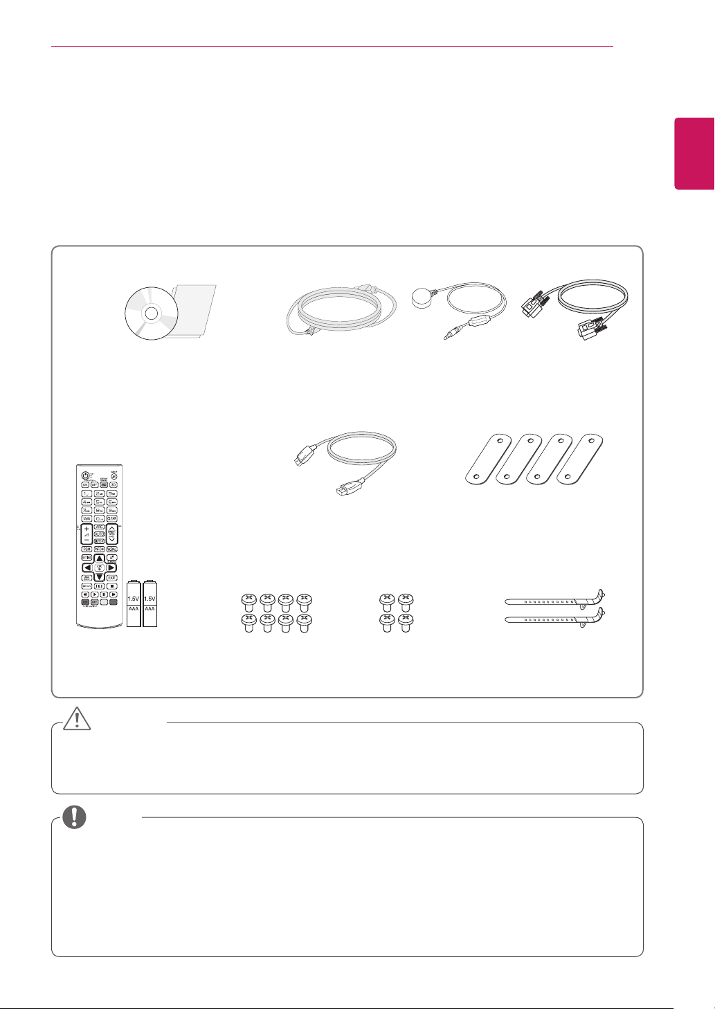
Check your product box for the following items. If there are any missing accessories, contact the local
dealer where you purchased your product. The illustrations in this manual may differ from the actual product
and accessories.
CD (Owner's Manual) /
Cards
Power Cord IR Receiver RS-232C Cable
ENGLISH
ENG
Remote Control
and Batteries
M4 x 6L
Screws (8 ea)
DP Cable
M6 x 10L
Screws (4 ea)
Tiling Guide (4 ea)
Mounting Cable Tie (2 ea)
(For Cable Arrangement)
CAUTION
Do not use any pirated items to ensure the safety and product life span.
y
Any damages or injuries by using pirated items are not covered by the warranty.
y
NOTE
The accessories supplied with your product may vary depending on the model.
y
Product specifications or contents in this manual may be changed without prior notice due to upgrade
y
of product functions.
SuperSign SW & Manual
y
- Downloading from the LG Electronics website.
- Visit the LG Electronics website (https://www.lgecommercial.com/supersign) and download the
latest software for your model.
Page 6
ASSEMBLING AND PREPARING
6
ENGLISH
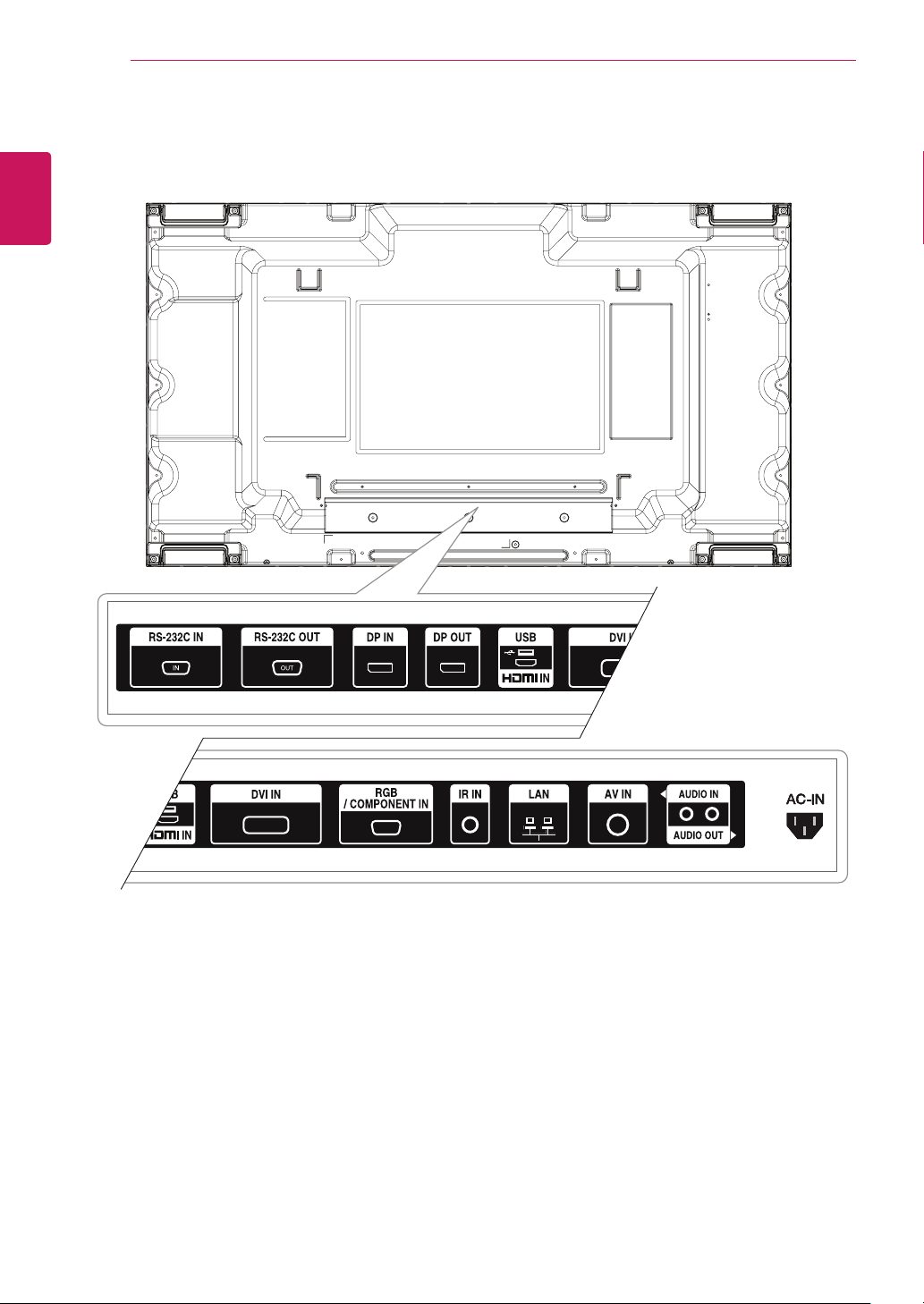
Parts
ENG
Page 7

ASSEMBLING AND PREPARING
7
To Install in a Portrait Layout
When installing in a Portrait Layout, rotate the monitor clockwise 90 degrees (when facing the screen).
Remove L-brackets before Installation
Remove the L-brackets from each corner of the monitor before installing it.
ENGLISH
ENG
NOTE
Keep the removed L-brackets and use them when moving the monitor later.
y
Page 8

ASSEMBLING AND PREPARING
8
ENGLISH
STORAGE METHOD FOR PANEL PROTECTION
ENG
Correct Method Incorrect Method
If the product needs to be set upright, hold both
sides of the product, and tilt backward carefully
for. Do not let the panel not to touch the floor.
Panel
Panel
If the product is tilted onto the bezel, the bottom of
the panel may be damaged.
Panel
When laying down the product, lay a cushion on a
flat floor. Put the product on it with the panel of
the product facing down.
Cushion
Panel
If there is not a cushion available, ensure the floor
is clean and then lay the product down carefully
with the panel facing either upward or downward.
At this time, be careful for objects not to fall on the
panel.
Panel
If the product is tilted onto the edge of the panel,
the panel may be damaged.
Page 9
ASSEMBLING AND PREPARING
9
Installing on a Wall
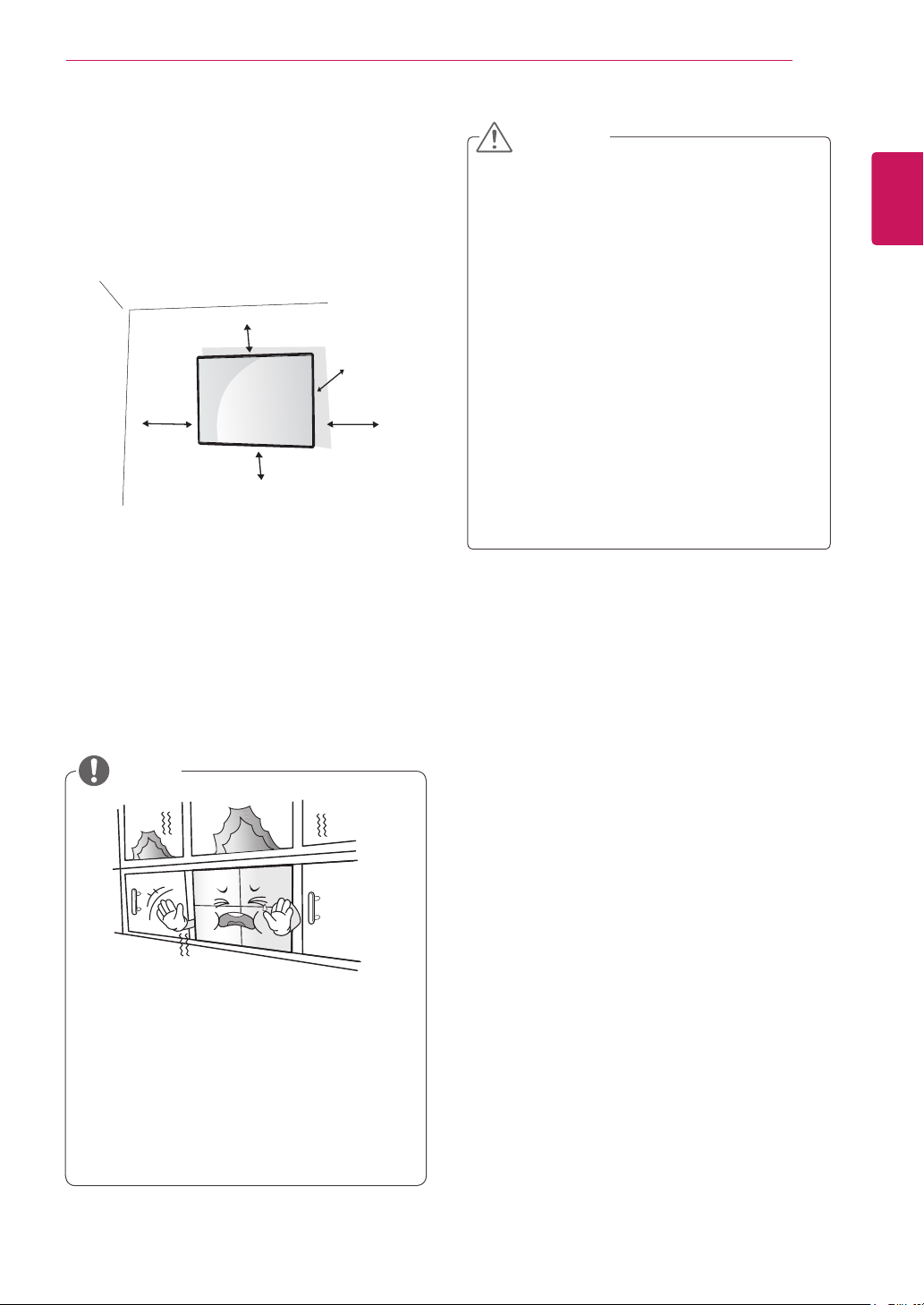
To install the Monitor on a wall (optional),
use the VESA screws provided as accessories to
fasten it.
10 cm
20 cm
10 cm
10 cm
Install the monitor at least 10 cm away from the
wall and leave about 20 cm of space at each side
of the monitor to ensure sufficient ventilation.
Use the wall mount plate and screws that comply
with the VESA standard.
10 cm
CAUTION
Disconnect the power cord first, and then
y
move or install the monitor set. Otherwise
electric shock may occur.
If you install the monitor set on a ceiling or
y
slanted wall, it may fall and result in severe
injury.
Do not over tighten the screws as this may
y
cause damage to the monitor set and void
your warranty.
Use the screws and wall mounts that meet
y
the VESA standard. Any damages or injuries
by misuse or using an improper accessory
are not covered by the warranty.
To prevent injury, this apparatus must be
y
securely attached to the wall in accordance
with the instrallation instructions. (This only
pertains to Australia and New Zealand.)
ENGLISH
ENG
NOTE
Do not install the product in a place with
no ventilation (e.g., on a bookshelf or in a
closet) or on a carpet or cushion. If there is
no other option but to mount the product on
the wall, make sure that sufcient ventilation
is provided before installation.
- Failure to do so may result in a re due to
the increase in the internal temperature.
Page 10

ASSEMBLING AND PREPARING
10
ENGLISH
ENG
(Depending on model)
1
Securing the product to a wall (optional)
Insert and tighten the eye-bolts, or product
brackets and bolts on the back of the product.
- If there are bolts inserted at the eye-bolts
position, remove the bolts first.
WARNING
If a product is not positioned in a sufficiently
y
stable location, it can be potentially
hazardous due to falling. Many injuries,
particularly to children, can be avoided by
taking simple precautions such as:
»Using cabinets or stands recommended
by the manufacturer of the product.
»Only using furniture that can safely
support the product.
»Ensuring the product is not overhanging
the edge of the supporting furniture.
»Not placing the product on tall furniture
(for example, cupboards or bookcases)
without anchoring both the furniture and
the product to a suitable support.
»Not standing the product on cloth or other
materials placed between the product
and supporting furniture.
»Educating children about the dangers of
climbing on furniture to reach the product
or its controls.
Mount the wall brackets with the bolts to the
2
wall.
Match the location of the wall bracket and the
eye-bolts on the rear of the product.
Connect the eye-bolts and wall brackets tightly
3
with a sturdy rope.
Make sure to keep the rope horizontal with the
flat surface.
CAUTION
Make sure that children do not climb on or
y
hang on the product.
NOTE
Use a platform or cabinet that is strong and
y
large enough to support the product securely.
Brackets, bolts, and ropes are optional. You
y
can obtain additional accessories from your
local dealer.
The illustration shows a general example of
y
installation and may look different from the
actual product.
Page 11
ASSEMBLING AND PREPARING
11
EXTERNAL EQUIPMENT SETUP
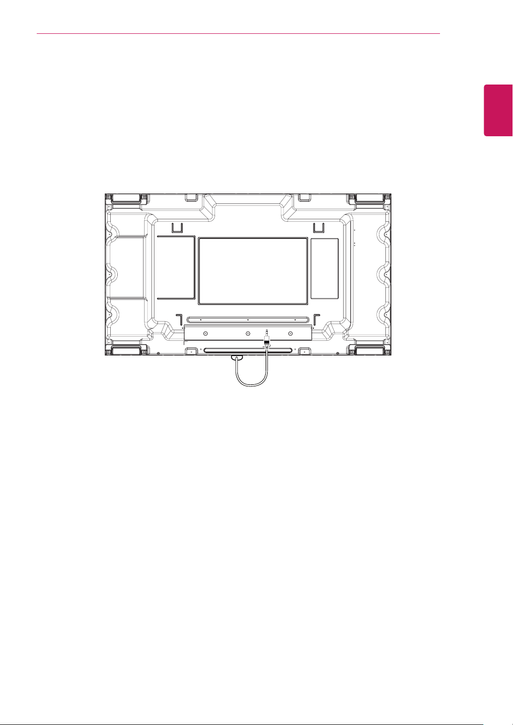
IR RECEIVER
This allows a remote control sensor to be placed in a custom location. Then that display can control other
displays via an RS-232C cable.
ENGLISH
ENG
Page 12
ASSEMBLING AND PREPARING
12
ENGLISH
Tiling Displays
ENG
How to Mount the Set
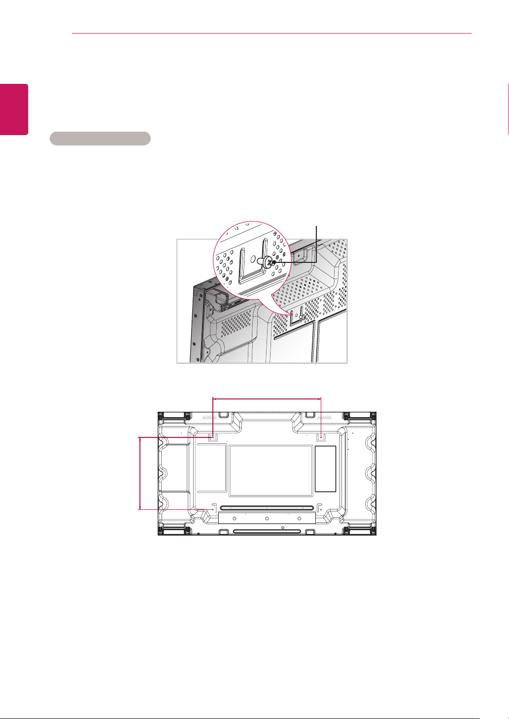
Using the screws for attaching the VESA wall mount, mount the set to the wall mount plate or the wall.
Example of 2 x 2 Tiling
Screws for attaching the
VESA wall mount (M6)
400
600
Page 13

ASSEMBLING AND PREPARING
How to Join Sets
1 Join other sets using screws for xing the VESA wall mount in the same way as above.
Set 4 joined to the rest of the sets
(2 x 2 tiling)
2 After joining the sets, use the tiling guide to adjust the gap between the sets.
13
ENGLISH
ENG
3 Now the 2 x 2 tiling is complete.
You can tile in various combinations, such as 3 x 3.
NOTE
The load applied to each set should be supported by the wall mount plate or the wall using a VESA
y
wall mount (600 x 400).
The load applied to each set should be supported by the wall mount plate using a VESA wall mount.
y
(Each set must be firmly mounted to the wall mount plate or the wall.)
You may mount the set without using the tiling guide; this does not affect the performance of the
y
device.
The screws are enclosed with the other components in the box, including the tiling guides.
y
Page 14
REMOTE CONTROL
14
ENGLISH
REMOTE CONTROL
ENG
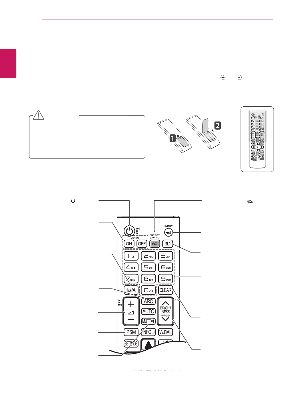
The descriptions in this manual are based on the buttons of the remote control. Please read this manual
carefully and use the monitor set correctly.
To replace batteries, open the battery cover, replace batteries (1.5 V AAA) matching and ends to the
label inside the compartment, and close the battery cover.
To remove the batteries, perform the installation actions in reverse.
CAUTION
Do not mix old and new batteries, as this
y
may damage the remote control.
Make sure to point the remote control to the
y
remote control sensor on the monitor set.
(POWER)
Turns the monitor set on or off.
MONITOR ON
Turn on the monitor.
MONITOR OFF
Turn off the monitor.
ENERGY SAVING( )
Adjusts the brightness of
the screen to reduce energy
consumption.
INPUT
Selects the input mode.
1/a/A Button
Toggles between numerical
and alphabetical.
ARC
Selects the Aspect Ratio
Mode.
Volume Up / Down
This button does not apply to
this model.
PSM
Selects the Picture Status
Mode.
MUTE
Mutes all sounds.
3D
This button does not apply to
this model.
Number and Alphabet Buttons
Enters numerical or alphabetical
characters depending on the
setting.
CLEAR
Deletes the entered numerical
or alphabetical character.
BRIGHTNESS Key
Adjust the brightness by
pressing the Up and Down
buttons on the remote control.
In USB mode, the OSD menu
has the Page function to move
to the next file list.
Page 15
REMOTE CONTROL
15
ENGLISH
ENG
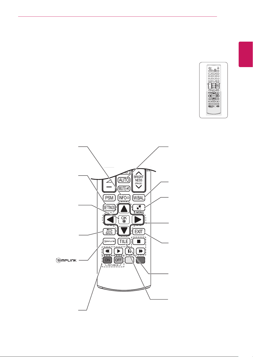
INFO
Displays the input
information.
SETTINGS
Accesses the main menus
or saves your input and exit
menus.
OK
Selects menus or options and
confirms your input.
BACK
Allows the user to move back
one step in user interaction
function.
Allows you to control various
multimedia devices simply
by using the remote control
through the SimpLink menu.
(It may not be supported
depending on the model.)
ⓘ
AUTO
Automatically adjusts picture
position and minimizes image
instability.(RGB input only)
W.BAL
Enters the White Balance
menu.
S.MENU
(SuperSign Menu Key)
This button does not apply to
this model.
Navigation Buttons
Scrolls through menus or
options.
EXIT
Clears all on-screen displays
and returns to Monitor set
viewing from any menu.
TILE
Selects the TILE Mode.
ID ON/OFF
When the number of Picture
ID is equal to Set ID you can
control the monitor which
you want in the multi display
condition.
USB Menu control buttons
Controls media playback.
Page 16
REMOTE CONTROL
16
ENGLISH
Displaying the Device Name Connected to an Input Port
ENG
Display which devices are connected to which
external input ports.
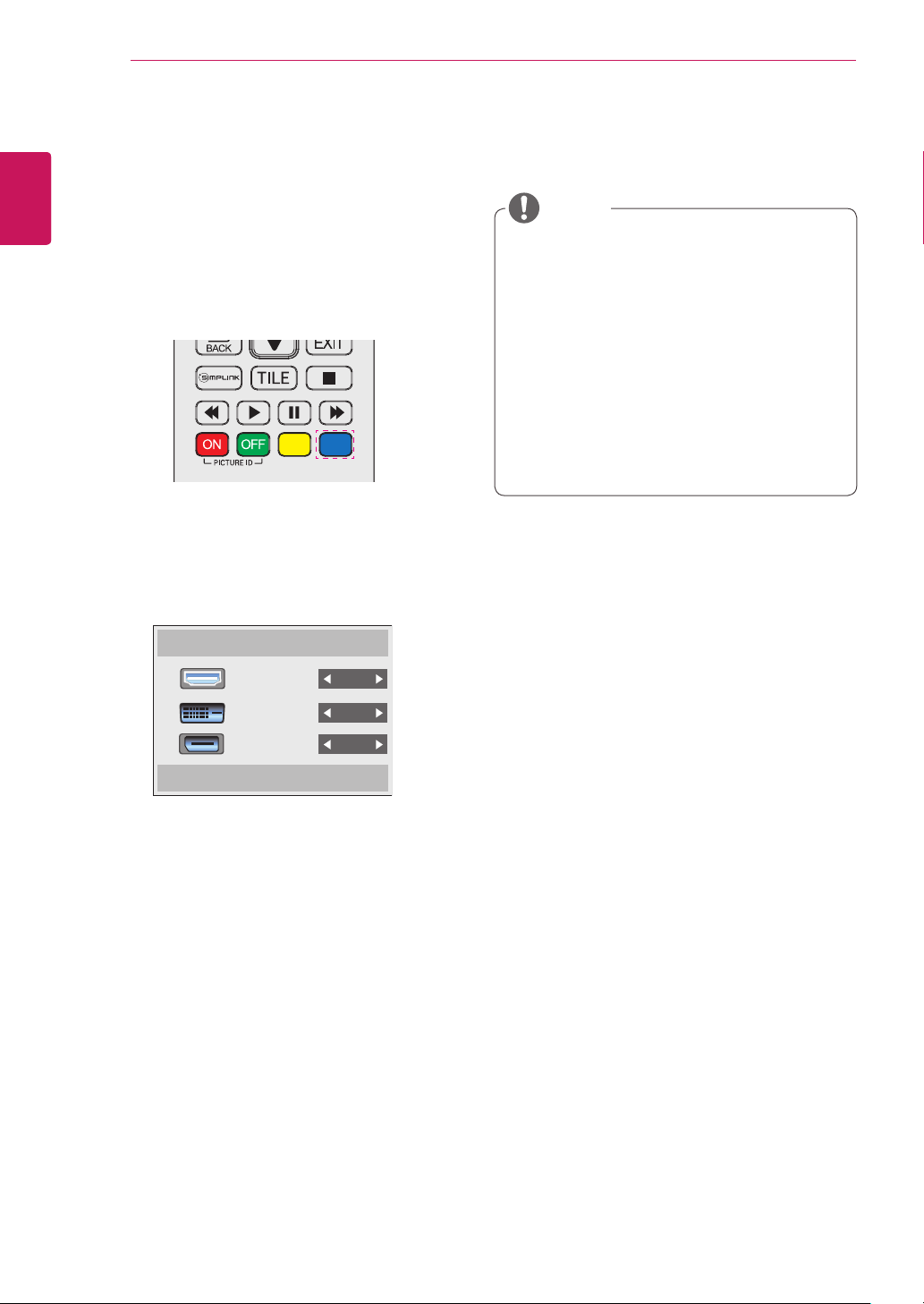
1 Access the Input list screen and press the blue
2 You can assign an input label for every input
(input label) button on the remote control.
except USB.
Input Label
NOTE
External inputs supported: HDMI, DVI-D,
y
Display Port
Labels available: PC, DTV
y
The input labels are displayed on the Input
y
Label screen or at the top left of the screen
when you change the external input setting.
For DTV/PC-compatible signals, such as
y
1080p 60 Hz, the screen settings may
change according to the input label. The Just
Scan option is available if a PC is connected
as an external device.
HDMI
DVI-D
Display Port
Close
Page 17

USING THE MONITOR SET
17
USING THE MONITOR SET
Connecting to a PC
Your Monitor set supports the Plug & Play* feature.
* Plug & Play: A PC will have a built-in driver for
the monitor, no extra software is needed.
NOTE
It is recommended to use the monitor set
y
with the HDMI connection for the best image
quality.
To comply with the specifications of the
y
product, use a shielded interface cable with
ferrite core, such as a D-sub 15-pin cable
and DVI/HDMI cable.
If you turn the monitor set on when the set
y
becomes cold, the screen may flicker. This is
normal.
Some red, green, or blue spots may appear
y
on the screen. This is normal.
To minimize the impact of electromagnetic
y
waves, secure the cables with cable ties.
RGB Connection
Transmits the analog video signal from your PC to
the monitor set. Connect the PC and the Monitor
set with the 15-pin signal cable as shown the
following illustrations.
Select RGB input.
included)
(not
ENGLISH
ENG
Back of the product.
15-pin D-Sub Signal
Cable (Max 3m)
Macintosh Adapter
(not included)
(not included)
CAUTION
Connect the signal
y
input cable and tighten
it by turning the screws
clockwise.
Do not press the screen with your finger for
y
a long time as this may result in temporary
distortion on the screen.
Avoid displaying a fixed image on the
y
screen for a long period of time to prevent
image burn. Use a screensaver if possible.
PC/ MAC
NOTE
Use the standard
y
Macintosh adapter since
an incompatible adapter
is available in the market.
(Different signaling system)
Apple computers may require an adapter to
y
connect to this monitor. Call or visit their web
site for more information.
Page 18

USING THE MONITOR SET
18
DVI Connection
ENGLISH
ENG
Transmits digital video signal from your PC to
the monitor set. Connect the PC and the monitor
set with the DVI cable as shown the following
illustrations.
Select DVI input.
(not
included)
HDMI Connection
Transmits digital video and audio signals from your
PC to the monitor set. Connect the PC and the
monitor set with the HDMI cable as shown in the
following illustrations.
Select HDMI input.
Back of the product. Back of the product.
(not included)
(not included)
PC PC
NOTE
Use a High Speed HDMI™ Cable.
y
Please check the PC environment if you
y
cannot hear the sound in HDMI mode. Some
PCs require you to manually change the
default audio output to HDMI.
If you want to use HDMI-PC mode, you must
y
set the input label to PC mode.
When HDMI PC is used, a compatiblity
y
problem could occur.
Page 19
USING THE MONITOR SET
19
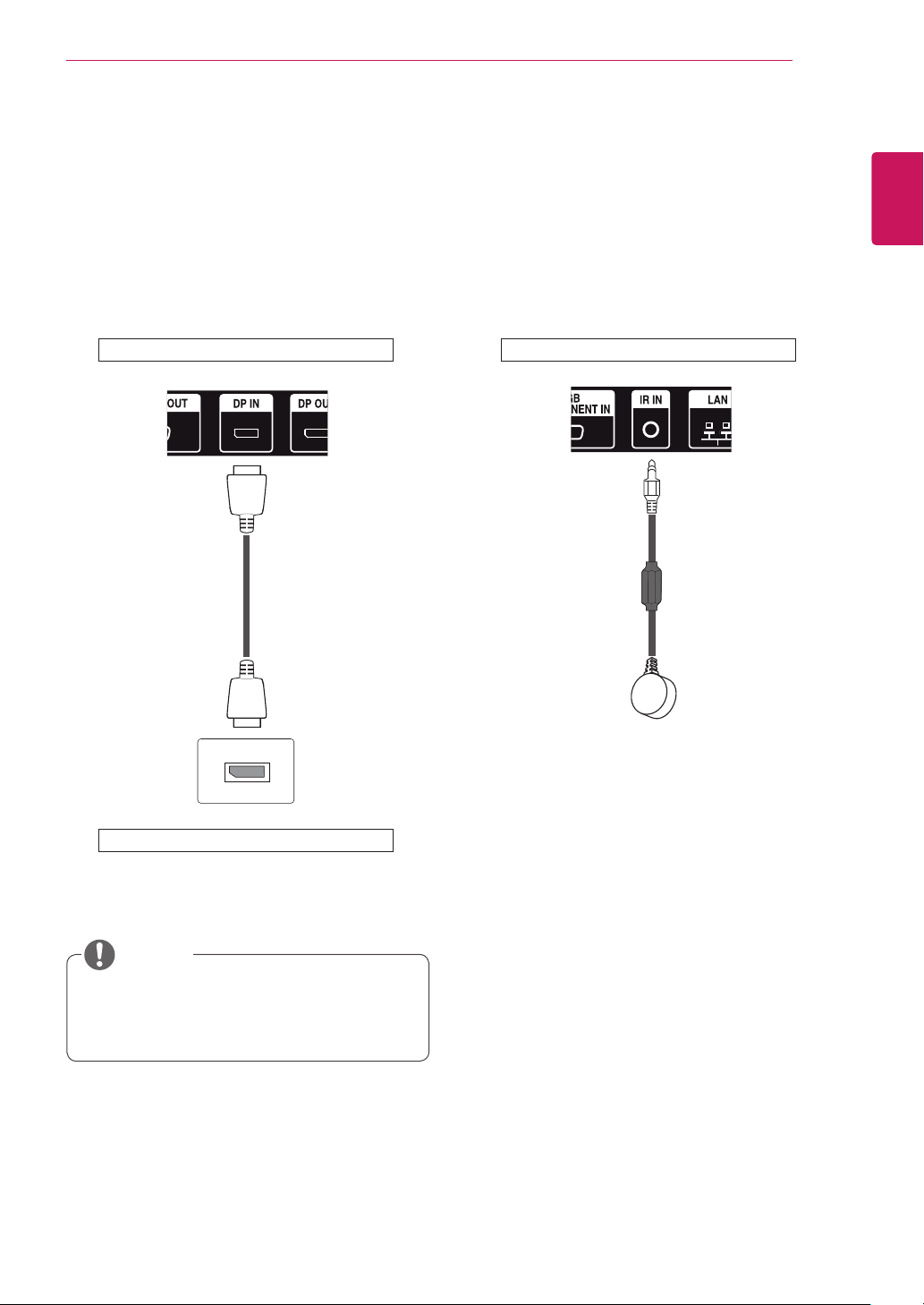
Display Port Connection
Transmits digital video and audio signals from
your PC to the Monitor. Connect the PC and the
Monitor with the Display Port cable as shown in
the following illustrations.
Select Display Port input source.
IR Receiver Connection
Allows the use of IR receiver extension.
Back of the product.Back of the product.
ENGLISH
ENG
PC
NOTE
Sound may not be available depending on
y
the DP version of your PC.
Page 20

USING THE MONITOR SET
20
ENGLISH
Adjusting the Screen
ENG
Selecting an Image Mode
Display images in its optimized settings by
selecting one of the preset image modes.
1
2
3
4
5
Press
SETTINGS
to access the main menus.
Press the navigation buttons to scroll to
PICTURE
and press OK.
Press the navigation buttons to scroll to
Picture Mode
and press OK.
Press the navigation buttons to scroll to an
image mode you want and press OK.
Mode Description
Vivid
Standard
Cinema
Sport
Game
When you are finished, press
Adjusts the video image for the retail
environment by enhancing the contrast,
brightness, color, and sharpness.
Adjusts the image for the normal
environment.
Optimizes the video image for a cinematic
look to enjoy movies as if you are in a
movie theater.
Optimizes the video image for high and
dynamic actions by emphasizing primary
colors such as white, grass, or sky blue.
Optimizes the video image for a fast
gaming screen such as PCs or games.
EXIT
.
When you return to the previous menu, press
BACK
.
Customizing Image Options
Customize basic and advanced options of each
image mode for the best screen performance.
Press
1
Press the navigation buttons to scroll to
2
Press the navigation buttons to scroll to
3
Press the navigation buttons to scroll to an
4
Select and adjust following options, and then
5
Backlight
Contrast
Brightness
Sharpness
Color
Tint
Color Temp.
Advanced
Control
Picture Reset
SETTINGS
PICTURE
and press OK.
Picture Mode
to access the main menus.
and press OK.
image mode you want and press OK.
press OK.
Option Description
Adjusts the brightness of the screen
by controlling the LCD backlight. If
you decrease the brightness level,
the screen becomes darker and the
power consumption will be reduced
without any video signal loss.
Increases or decreases the gradient
of the video signal. You may use
Contrast when the bright part of the
picture is saturated.
Adjusts the base level of the signal in
the picture. You may use Brightness
when the dark part of the picture is
saturated.
Adjusts the level of crispness in the
edges between the light and dark
areas of the picture. The lower the
level, the softer the image.
Adjusts intensity of all colors.
Adjusts the balance between red and
green levels.
Set to warm to enhance hotter Colors
such as red, or set to cool to make
picture bluish.
Customizes the advanced options.
Refer to the Advanced image options.
Restores the options to the default
setting.
When you are finished, press
6
EXIT
.
When you return to the previous menu, press
BACK
.
Page 21
Customizing PC Display Options
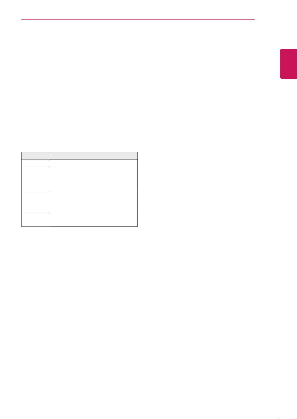
Customize options of each image mode for the
best image quality.
This function works in the following mode:
y
RGB [PC] mode.
USING THE MONITOR SET
21
ENGLISH
ENG
Press
1
Press the navigation buttons to scroll to
2
Press the navigation buttons to scroll to
3
Select and adjust following options, and then
4
Resolution
Auto
Config.
Position/
Size/Phase
Reset
When you are finished, press
5
SETTINGS
PICTURE
and press OK.
press OK.
Option Description
When you return to the previous menu, press
BACK
and press OK.
Selects a proper resolution.
Sets to adjust the screen position, clock,
and phase automatically. The displayed
image may be unstable for a few seconds
while the configuration is in progress.
Adjusts the options when the picture is
not clear, especially when characters are
shaky, after the auto configuration.
Restores the options to the default
setting.
.
to access the main menus.
Screen
EXIT
.
Page 22

USING THE MONITOR SET
22
ENGLISH
Using Additional Options
ENG
Adjusting Aspect Ratio
Resize the image to view the image at its optimal size by pressing
ARC
while you are watching Monitor set.
CAUTION
If a fixed image displays on the screen for a long period of time, it could be imprinted and become
y
a permanent disfigurement on the screen. This is image burn or burn-in and not covered by the
warranty.
If the aspect ratio is set to 4:3 for a long period of time, image burn may occur on the letterboxed area
y
of the screen.
NOTE
You can also change the image size by accessing the main menus.
y
MODE
Aspect Ratio
16:9
Just Scan
1:1
4:3
Zoom
Cinema Zoom 1~16
AV Component RGB DVI-D HDMI Display Port
PC DTV PC DTV PC DTV PC
o o o o o o o o o
x o x o x o x o x
x x o x o x o x o
o o o o o o o o o
o o x o x o x o x
o o x o x o x o x
Page 23

USING THE MONITOR SET
23
16:9
-
: This selection will allow you to adjust the
picture horizontally, in linear proportion, to fill the
entire screen(useful for viewing 4:3 formatted
DVDs).
Just Scan
-
the picture of best quality without loss of original
picture in high resolution image. Note: If there is
noise in original Picture, You can see the noise
at the edge.
: This Selection will allow you view
4:3
-
: This selection will allow you to view a
picture with an original 4:3 aspect ratio, black
bars will appear on both the left and right of the
screen.
Zoom
-
: This selection will allow you to view the
picture without any alteration, while filling the
entire screen. However, the top and bottom of
the picture will be cropped.
ENGLISH
ENG
Just Scan
1:1
-
: The aspect ratio is not adjusted from the
original. (Only Display Port PC, HDMI PC,
DVI-D PC, RGB PC)
Cinema Zoom 1~16
-
when you want to enlarge the picture in correct
proportion.
Note: When enlarging or reducing the picture,
the image may become distorted.
: Choose Cinema Zoom
Page 24
24
Using the Input List
ENGLISH
ENG
USING THE MONITOR SET
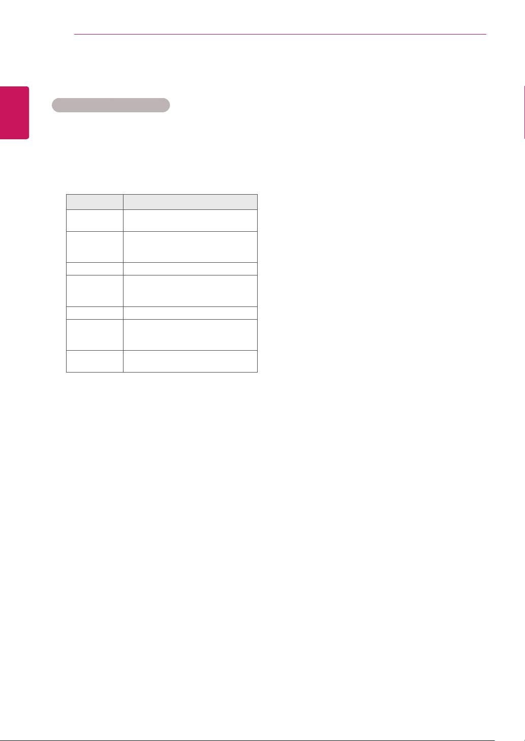
Selecting an Input Source
Press
1
Press the navigation buttons to scroll to one of
2
INPUT
to access the input source list.
the input sources and press OK.
Input source Description
AV
Component
RGB
HDMI
DVI-D
Display Port
USB
Watch video from a VCR or other
external devices.
Watch the content from a DVD or
other external devices, or through a
digital set-top box.
View a PC display on the screen.
Watch contents from a PC, DVD
of Digital set-top box other high
definition devices.
View a PC display on the screen.
Watch contents in a PC, DVD
of Digital set-top box other high
definition devices.
Plays the multimedia file saved in
the USB.
Page 25
ENTERTAINMENT
25
ENTERTAINMENT
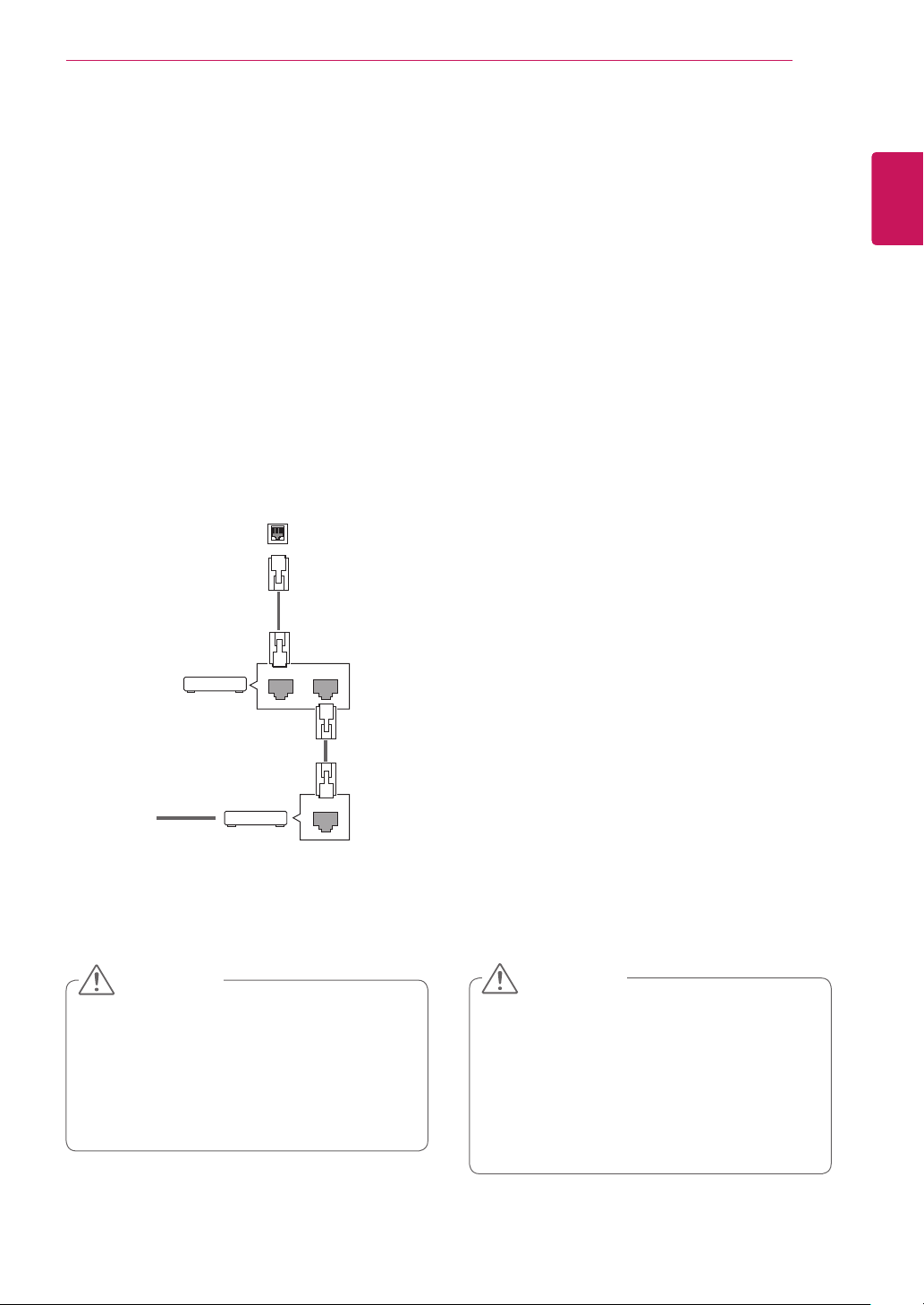
Connecting to a Wired Network
Connect the display to a local area network (LAN)
via the LAN port as shown on the following illustration and set up the network settings.
Only supports wired network connection.
After making a physical connection, a small
number of networks may require the display network settings to be adjusted. For most networks,
the display will connect to automatically without
any adjustments.
For detail information, contact your internet provider or router manual.
LAN
Router
Router
LAN WAN
ENGLISH
ENG
To set up the network settings: (Even if your display has already connected automatically, running
setup again will not harm anything),
1 Press SETTINGS to access the main menus.
2 Press the navigation buttons to scroll to NET-
WORK and press OK.
3 Press the navigation buttons to select Network
Setting and press OK.
4 If you already set Network Setting, select
Resetting. The new connection settings resets
the current network settings.
5 Select IP Auto Setting or IP Manual Setting.
- IP Manual Setting: Press the navigation and
number buttons. IP addresses will need to be
input manually.
- IP Auto Setting: Select this if there is a
DHCP server (Router) on the local area network (LAN) via wired connection, the display
will automatically be allocated an IP address.
If you’re using a broadband router or broadband modem that has a DHCP (Dynamic
Host Configuration Protocol) server function.
The IP address will automatically be determined.
@
Internet
Internet
Cable modem
Cable modem
ETHERNET
CAUTION
y Do not connect a modular phone cable to
the LAN port.
y Since there are various connection meth-
ods, please follow the specifications of your
telecommunication carrier or internet service
provider.
6 When you are finished, press EXIT.
CAUTION
y Network setting menu will not be avail-
able until the display connected to physical
network.
y Since there are various connection meth-
ods, please follow the specifications of your
telecommunication carrier or internet service
provider.
Page 26
ENTERTAINMENT
26
ENGLISH
ENG
NOTE
y If you want to access the Internet directly on
your display, the Internet connection should
always be on.
y If you cannot access the Internet, check
the network conditions from a PC on your
network.
y When you use Network Setting, check the
LAN cable or check if DHCP in the router is
turned on.
y If you do not complete the network settings,
the network may not work properly.
Tips for Network Setting
y Use a standard LAN cable with this display.
Cat5 or better with a RJ45 connector.
y Many network connection problems during set
up can often be fixed by re-setting the router
or modem. After connecting the display to the
network, quickly power off and/or disconnect
the power cable of the network router or cable
modem. Then power on and/or connect the
power cable again.
y Depending on the Internet service provider
(ISP), the number of devices that can receive
Internet service may be limited by the applicable terms of service. For details, contact your
ISP.
y LG is not responsible for any malfunction of the
display and/or the Internet connection feature
due to communication errors/malfunctions associated with your Internet connection, or other
connected equipment.
y LG is not responsible for problems within your
internet connection.
y You may experience undesired results if the
network connection speed does not meet the
requirements of the content being accessed.
y Some internet connection operations may not
be possible due to certain restrictions set by
the Internet service provider (ISP) supplying
your Internet connection.
y Any fees charged by an ISP including, without
limitation, connection charges are your responsibility.
y A 10 Base-T or 100 Base-TX LAN port is
required when using a wired connection to this
display. If your internet service does not allow
for such a connection, you will not be able to
connect the display.
y A DSL modem is required to use DSL service
and a cable modem is required to use cable
modem service. Depending on the access
method of and subscriber agreement with your
ISP, you may not be able to use the internet
connection feature contained in this display or
you may be limited to the number of devices
you can connect at the same time. (If your ISP
limits sub-scription to one device, this display
may not be allowed to connect when a PC is
already connected.)
y The use of a “Router” may not be allowed or its
usage may be limited depending on the policies and restrictions of your ISP. For details,
contact your ISP directly.
Network Status
1 Press SETTINGS to access the main menus.
2 Press the navigation buttons to scroll to
NETWORK and press OK.
3 Press the navigation buttons to select
Network Status.
4 Press OK to check the network status.
5 When you are finished, press EXIT.
Option Description
Setting Return to the network setting menu.
Test
Close Return to the previous menu.
Test the current network status after set-
ting the network.
Page 27
ENTERTAINMENT
27
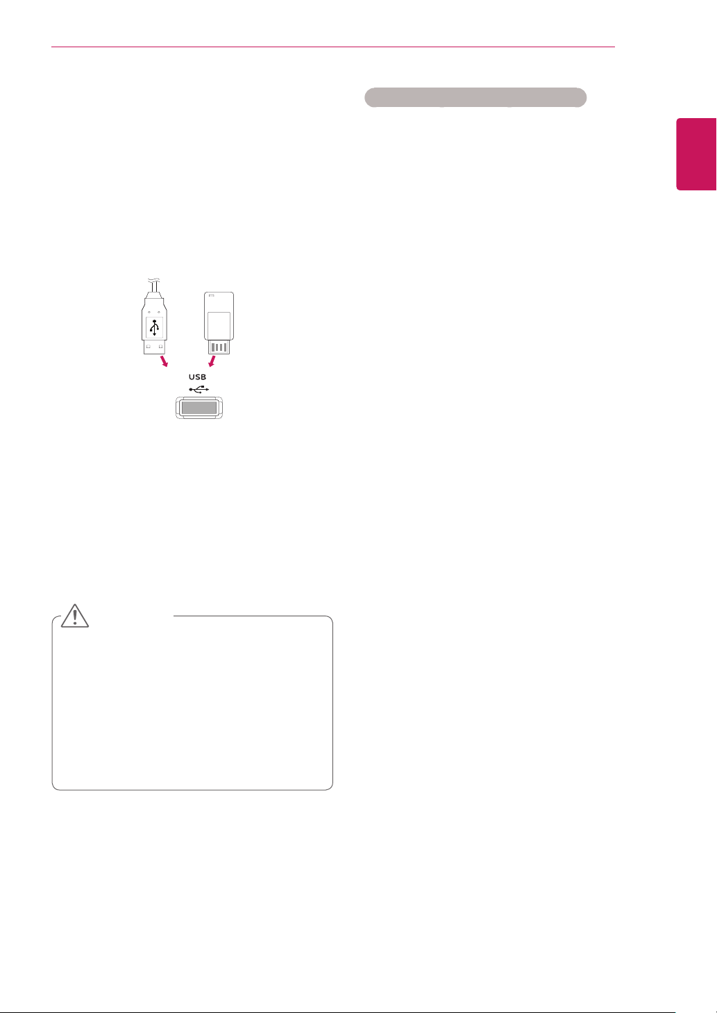
Connecting USB Storage Devices
Connect USB storage devices such as a USB
flash memory, external hard drive to the display
and use multimedia features.
Connect a USB flash memory or USB memory
card reader to the Display as shown on the following illustration. The My media screen appears.
or
CAUTION
y Do not turn the display off or remove a USB
storage device while EMF (my media) Menu
is activated, as this could result in loss of
files or damage to the USB storage device.
y Back up your files saved on a USB storage
device frequently, as you may lose or damage the files and this may be not covered by
the warranty.
Tips for Using USB Storage Devices
y Only a USB storage device is recognizable.
y If the USB storage device is connected
through a USB hub, the device is not recog-
nizable.
y A USB storage device using an automatic
recognition programme may not be recog-
nized.
y A USB storage device which uses its own
driver may not be recognized.
y The recognition speed of a USB storage
device may depend on each device.
y Please do not turn off the display or unplug
the USB device when the connected USB
storage device is working. When such device
is suddenly separated or unplugged, the
stored files or the USB storage device may
be damaged.
y Please do not connect the USB storage
device which was artificially maneuvered on
the PC. The device may cause the product to
malfunction or fail to be played. Never forget
to use only a USB storage device which has
normal music files, image files or movie files.
y Please use only a USB storage device which
was formatted as a FAT32 file system, NTFS
file system provided with the Windows op-
erating system. In case of a storage device
formatted as a different utility program which
is not supported by Windows, it may not be
recognized.
y Please connect power to a USB storage de-
vice (over 0.5 A) which requires an external
power supply. If not, the device may not be
recognized.
y Please connect a USB storage device with
the cable offered by the device maker.
y Some USB storage devices may not be sup-
ported or operated smoothly.
y File alignment method of USB storage
device is similar to Window XP and filename
can recognize up to 100 English characters.
ENGLISH
ENG
Page 28
ENTERTAINMENT
28
ENGLISH
ENG
y Be sure to back up important files since data
stored in a USB memory device may be
damaged. We will not be responsible for any
data loss.
y If the USB HDD does not have an external
power source, the USB device may not be
detected. So be sure to connect the external
power source.
- Please use a power adaptor for an external
power source. We do not guarantee an USB
cable for an external power source.
y If your USB memory device has multiple
partitions, or if you use a USB multi-card
reader, you can use up to 4 partitions or USB
memory devices.
y If a USB memory device is connected to a
USB multi-card reader, its volume data may
not be detected.
y If the USB memory device does not work
properly, disconnect and reconnect it.
y How fast a USB memory device is detected
differs from device to device.
y If the USB is connected in Standby Mode,
specific hard disk will automatically be
loaded when the display is turned on.
y The recommended capacity is 1 TB or less
for a USB external hard disk and 32 GB or
less for USB memory.
y Any device with more than the recommended
capacity may not work properly.
y If a USB external hard disk with a “Energy
Saving” function does not work, turn the
hard disk off and on again to make it work
properly.
y USB storage devices below USB 2.0 are
supported as well. But they may not work
properly in the movie list.
y Maximum of 999 folders or files can be rec-
ognized under one folder.
y A USB 3.0 storage device may not work.
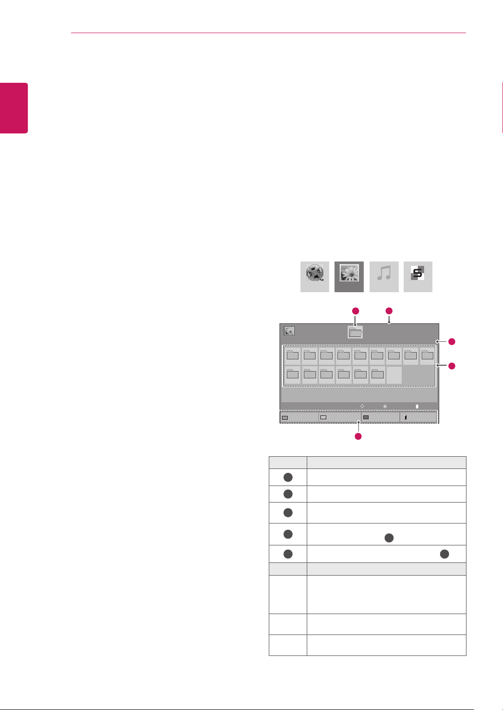
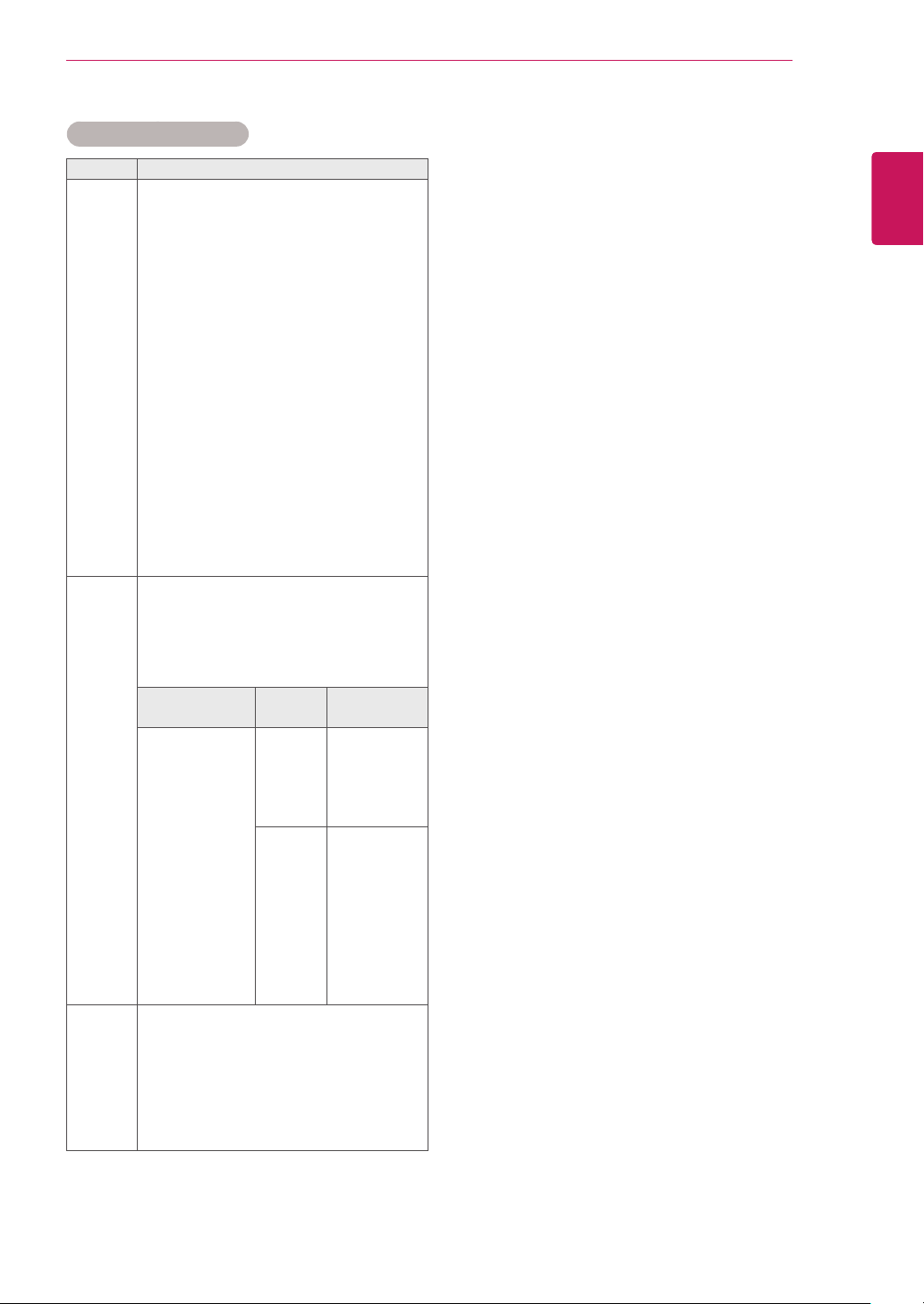
Browsing Files
Access the photo, music, or movie lists and browse
files.
Connect a USB storage device.
1
Press
2
Press the navigation buttons to scroll to
3
Press the Navigation buttons to choose
4
Button Description
Green
button
Yellow
button
button
SETTINGS
to access the main menus.
My
Media
and press OK.
Movie List, Photo List, Music List
from
Contents List
and press OK. (The function of
or
Contents List may not be supported depending
on the model.)
Movie List Music ListPhoto List Contents List
Move
Mark Mode
2
Page 1/1
View
1
008
P Page Change
Exit
.
Page 1/1
009
4
5
1
11
Photo List
USB External
001
002 003 004 005 006 007
010 011 012 013 014 015
To Music List
Drive1
Change Numbers
3
No. Description
Moves to upper level folder
1
Current page/Total pages
2
Corresponding buttons on the
3
remote control
Current page/ total pages of contents under
4
the folder focused on
5
Contents under the folder focused on
Press the green button to toggle between
Photo List -> Music List, Music List ->
Contents List, Contents List -> Movie List
Movie List -> Photo List
or
A method to view in 5 large thumbnail or
simple list.
Blue
Convert to Mark Mode.
Page 29
ENTERTAINMENT
29
Supported File Format
Type Supported file format
Movie
Photo
Music
DAT,MPG,MPEG,VOB,AVI,DIVX,MP4,MKV,TS,T
RP,TP,ASF,WMV,FLV)
Movie(*.mpg/*.mpeg/*dat/*.ts/*.trp/*.tp/*.vob/*.
mp4/*.mov/*.mkv/*.divx/*.avi/*.asf/*.wmv/*.flv/*.
avi(motion-jpeg)/*.
mp4(motion-jpeg)/*.mkv(motion-jpeg))supporting
file
Video format : DivX 3.11, DivX4, DivX5. DivX6
Xvid1.00, Xvid1.01, Xvid1.02, Xvid1.03, Xvid1.10
beta-1/beta-2,
Mpeg-1, Mpeg-2, Mpeg-4, H.264/AVC, VC1,
JPEG, Sorenson H.263
Audio format : Dolby Digital, AAC, Mpeg, MP3,
LPCM, HE-AAC, ADPCM, WMA
Bit rate : within 32 kbps to 320 kbps(MP3)
External Subtitle format : *.smi/*.srt/*.sub
(MicroDVD,Subviewer1.0/2.0)/*.ass/*.ssa/*.
txt(TMPlayer)/*.psb(PowerDivX)
Internal Subtitle format : only, XSUB (It is the
subtitle format used in DivX6 files)
JPEG
Baseline : 64 x 64 to 15360 x 8640
Progressive : 64 x 64 to 1920 x 1440
y You can play JPEG files only.
y Non-supported files are displayed in the form
of predefined icon.
File
Extensions
jpeg
jpg
jpe
MP3
Bit rate 32 to 320
y Sampling rate MPEG1 Layer3 : 32 kHz, 44.1
kHz, 48 kHz
y Sampling rate MPEG2 Layer3 : 16 kHz, 22.05
kHz, 24 kHz
y Sampling rate MPEG2.5 Layer3 : 8 kHz,
11.025 kHz, 12 kHz
Item Profile
supported
file format
photo size
ENGLISH
ENG
SOF0: baseline
SOF1: Extend
Sequential
SOF2:
Progressive
Min: 64 x 64
Max-Normal
Type:
15360 (W) x
8640 (H)
Progressive
Type:
1920 (W) x 1440
(H)
Page 30

ENTERTAINMENT
30
Viewing Movies
ENGLISH
ENG
Play video files on display. Your display shows all
of the video files saved in a USB storage device or
shared folder on a PC.
1 Press the navigation buttons to scroll to My
2 Press the navigation buttons to scroll to Movie
3 Press the navigation buttons to scroll to a
4 Press the navigation buttons to scroll to a file
Media and press OK.
List and press OK.
folder you want and press OK.
you want and press OK.
Movie List
Change Numbers
Drive1
Drive1
003
Mark Mode
003
051. Apple_ ......
02:30:25
USB1 USB Drive
001 002
005 006
To Photo list
Movie List
Mark Mode
USB1 USB Drive
001 002
005 006
Page 1/1
Move
Page 1/1
5 Play a movie.
6 Control playback by using the following buttons.
Option
01:02:30 / 02:30:25
Hide
Exit
MENU
Button Description
Stops the playback
Plays a video
Pauses or resumes the playback
Scans backward in a file
Page 1/1
004
SETTINGS
BACK
EXIT
Scans forward in a file
Show the Option menu.
Hide the menu on the full-sized screen.
Return to Movie List.
Skips to specific points in a file dur-
Play
Page ChangeP
Exit
or
ing playback. The time of a specific
point will appear on the status bar. In
some files, this function may not work
properly.
Page 1/1
004
ENERGY
SAVING
Adjusts the screen brightness to save
energy.
Play Marked
Mark All
Unmark All
Menu Description
Play Marked
Play the selected movie file.
Once a movie file finishes playing,
the next selected one will be played
automatically.
Mark All
Unmark All
Exit Mark
Mark all movie files on the screen.
Deselect all marked movie files.
Exit the Mark Mode.
Mode
Move
Exit Mark Mode
Page ChangeP
Mark
Exit
Page 31
ENTERTAINMENT
31
Tips for Using Playing Video Files
y Some user-created subtitles may not work
properly.
y Some special characters are not supported
in subtitles.
y HTML tags are not supported in subtitles.
y Subtitles in languages other than the sup-
ported languages are not available.
y The screen may suffer temporary interrup-
tions (image stoppage, faster playback, etc.)
when the audio language is changed.
y A damaged movie file may not be played
correctly, or some player functions may not
be usable.
y Movie files produced with some encoders
may not be played correctly.
y If the video and audio structure of recorded
file is not interleaved, either video or audio is
outputted.
y Videos with resolutions higher than
1920X1080@25/30P may not work properly
depending on the frame.
y Movie files other than the specified types and
formats may not work properly.
y Max bitrate of playable movie file is 20 Mbps.
(only, Motion JPEG : 10 Mbps)
y We do not guarantee smooth playback of
profiles encoded level 4.1 or higher in H.264/
AVC.
y DTS Audio codec is not supported.
y A movie file more than 30 GB in file size is
not supported for playback.
y A DivX movie file and its subtitle file must be
located in the same folder.
y A video file name and its subtitle file name
must be identical for it to be displayed.
y Playing a video via a USB connection that
doesn’t support high speed may not work
properly.
y Files encoded with GMC(Global Motion
Compensation) may not be played.
Video Options
1 Press SETTINGS to access the Pop-Up
menus.
2 Press the navigation buttons to scroll to Set
Video Play. or Set Video. and press OK.
NOTE
y Option values changed in Movie List does
not affect Photo List and Music List.
y Option value changed in Photo List and Mu-
sic List are changed likewise in Photo List
and Music List excluding Movie List.
y When replaying the video file after stopping,
you can play from where it stopped previously.
ENGLISH
ENG
Page 32
ENTERTAINMENT
32
When you select the Set Video Play,
ENGLISH
ENG
1 Press the navigation buttons to scroll to show
2 Press the navigation buttons to scroll to make
the Picture Size, Audio Language, Subtitle
Language, or Repeat.
appropriate adjustments.
Menu Description
Picture Size Selects your desired picture
format during movie play.
Audio
Language
Subtitle
Language
Language Activated for SMI subtitle and
Code Page Can select the font for subtitle.
Sync Adjusts the time synchronisation of
Position Changes the position of the
Size Selects your desired Subtitle size
Repeat Turn on/off repeat function of movie
Changes the Language Group of the
audio during movie play. Files with a
single audio track cannot be selected.
Turn on/off the subtitle.
can select the language within the
subtitle.
When set to default, same font as
general menu will be used.
the subtitle from -10 secs to +10 secs
by steps of 0.5 secs during movie
play.
subtitle either up or down during
movie play.
during movie play.
playback. When turned on, the file
within the folder will be played back
repeatedly. Even when the repeated
playback is turned off, it can run the
playback if the file name is similar to
the previous file.
Code Page Support Language
Latin1 English, Spanish, French,
German, Italian, Portuguese,
Danish, Romanian, Norwegian,
Albanian, Gaelic, Welsh, Irish,
Catalan,Valencian
Latin2 Bosnian, Polish, Croatian, Czech,
Slovak, Slovenian, Serbian,
Hungarian
Latin4 Estonian, Latvian, Lithuanian
Cyrillic Bulgarian, Macedonian, Russian,
Ukrainian, Kazakh
Greek Greek
Turkish Turkish
Korean Korean
NOTE
y Only 10,000 of sync blocks can be supported
within the subtitle file.
y When playing a video, you can adjust the
Picture Size by pressing the ARC button.
y Subtitles in your language are only sup-
ported when the OSD menu is also in this
language.
y The code page options may be disabled de-
pending on the language of the subtitle files.
y Select the appropriate code page for the
subtitle files.
For more details about the Set Video. menu, see
the CUSTOMIZE SETTINGS section. See p.42
Page 33
Viewing Photos
View image files saved in a USB storage device.
The displays on the screen may differ from the
model.
1 Press the navigation buttons to scroll to My
Media and press OK.
2 Press the navigation buttons to scroll to Photo
List and press OK.
3 Press the navigation buttons to scroll to a
folder you want and press OK.
4 Press the navigation buttons to scroll to a file
you want and press OK.
ENTERTAINMENT
33
ENGLISH
ENG
Photo List
USB1 USB Drive
001
002 003 004 005 006 007
010 011 012 013 014 015
To Music List
Photo List
Mark Mode
USB1 USB Drive
001
002 003 004 005 006 007
010 011 012 013 014 015
View Marked
Mark All
Drive1
Change Numbers
Drive1
Unmark All
Menu Description
View Marked
Mark All
Display the selected photo file.
Mark all photo files on the screen.
Mark Mode
Page 1/1
Move
Page 1/1
Move
Exit Mark Mode
Page 1/1
008
009
View
Page ChangeP
Exit
Page 1/1
008
009
Mark
Page ChangeP
Exit
Unmark All
Exit Mark Mode
5 View photos.
Deselect all marked photo files.
Exit the Mark Mode.
Page 34

ENTERTAINMENT
34
ENGLISH
ENG
Use the following options while viewing photos.
Using Photo Options
2/13
Hide
Slideshow BGM
MENU
Option
Exit
Number of selected photosOptions
Option Description
Slideshow Starts or stops a slideshow with selected
photos.
If there are no selected photos, all pho-
tos saved in the current folder display
during a slideshow.
To set a slideshow speed, select Op-
tion.
BGM Turns the background music on or off.
To set the background music folder,
select Option.
You can adjust Option by SETTINGS
button on the remote control.
Rotates photos clockwise (90°, 180°,
270°, 360°).
Option Description
ENERGY
SAVING
Adjusts the screen brightness to save
energy.
y Slide Speed: Selects a slideshow
speed (Fast, Medium, Slow).
y TransitionEffect: Set the view mode
of the slideshow.
y BGM: Selects a music folder for the
background music.
NOTE
y You cannot change the music
folder while the background
music is playing.
y You can only select the MP3
folder saved on the device that
currently displays the photo.
Hides the option window.
To display the options, press OK.
Return to Photo List.
Photo options
1 Press SETTINGS to show the Option menus.
2 Press the navigation buttons to scroll to Set
Photo View. or Set Video. and press OK.
NOTE
y The supported photo size is
limited. You cannot rotate a
photo if the resolution of the
rotated width is larger than the
supported resolution size.
View the photo by zoom in 2, 4 times.
NOTE
y Photos with a resolution of
960x540 or less cannot be
enlarged.
NOTE
y Option values changed in Movie List does
not affect Photo List and Music List.
y Option value changed in Photo List and Mu-
sic List are changed likewise in Photo List
and Music List excluding Movie List.
Page 35
ENTERTAINMENT
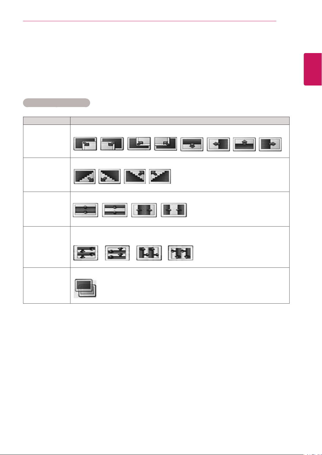
When you select the Set Photo View,
1 Press the navigation buttons to scroll to select Slide Speed,Transition Effect or BGM.
2 Press the navigation buttons to scroll to make appropriate adjustments.
Transition Effect Option
35
ENGLISH
ENG
Option
Sliding The current photo disappears horizontally, vertically or diagonally and the next photo appears.
Stairs The next photo appears and overlaps with the current photo in a staircase shape.
Door Open
/Close
Shutter The current photo disappears as though drawing or pulling down a blind and the next photo ap-
Fade In The current photo disappears and the next photo appears slowly.
The current photo disappears as though a door opens and closes, and the next photo appears.
pears slowly.
Description
For more details about the Set Video. menu, see the CUSTOMIZE SETTINGS section. See p.42
Page 36
ENTERTAINMENT
36
Listening to Music
ENGLISH
ENG
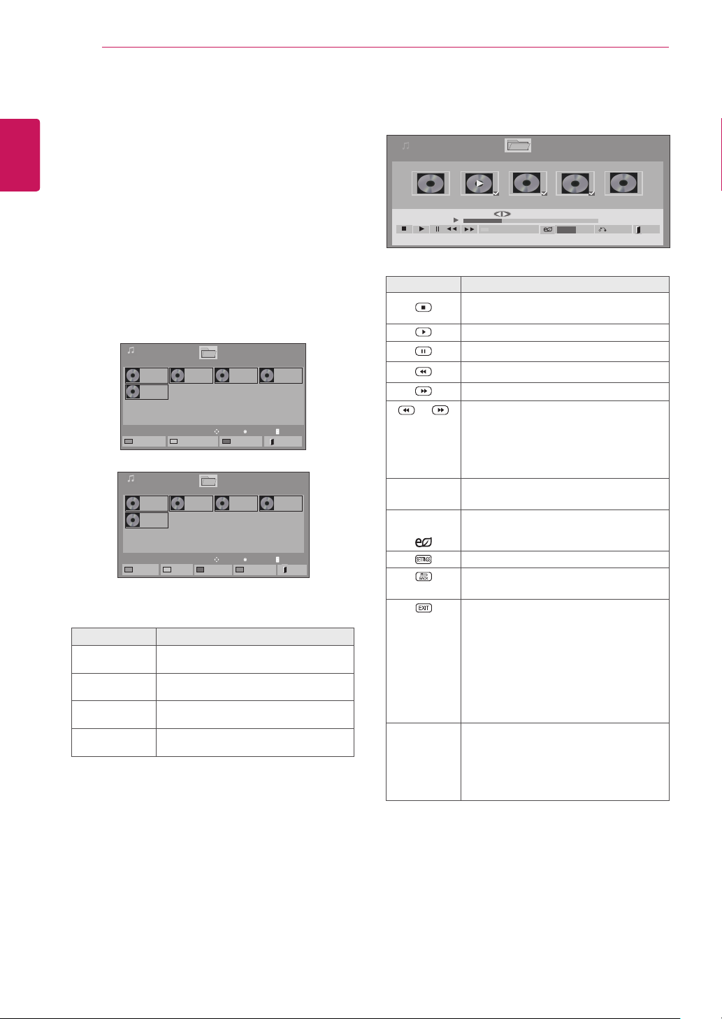
1 Press the navigation buttons to scroll to My Me-
2 Press the navigation buttons to scroll to Music
3 Press the navigation buttons to scroll to a folder
4 Press the navigation buttons to scroll to a file
5 Play music.
dia and press OK.
List and press OK.
you want and press OK.
you want and press OK.
Music List
USB1 USB Drive
001. - B01.mp3
00:00
005. - B05.mp3
00:00
To Movie List
Music List
Mark Mode
USB1 USB Drive
001. - B01.mp3
00:00
005. - B05.mp3
00:00
Play Marked
Menu Description
Play Marked
Mark All
Unmark All
Exit Mark Mode
Display the selected music file.
Mark all music files on the screen.
Deselect all marked music files.
Exit the Mark Mode.
Change Numbers
Mark All
002. -B02.mp3
00:00
002. -B02.mp3
00:00
Drive1
Drive1
Unmark All
Move
Move
003. B03.mp3
00:00
Mark Mode
003. B03.mp3
00:00
Page 1/1
Play
Page 1/1
Mark
Exit Mark Mode
004. - B04.mp3
00:00
Page ChangeP
Exit
004. - B04.mp3
00:00
Page ChangeP
Page 1/1
Page 1/1
6 Control playback by using the following buttons.
Music List
3 file(s) Marked
004. - B04.mp3
00:00
005. - B05.mp3
005. - B05.mp3
00:00
Drive1 Page 1/1
006. - B06.mp3
00:00
Play with Photo
Button Description
Stops playing back the file and moves
back to the music list.
Plays a music file.
Pauses or resumes playback.
Skips to the previous file.
Skips to the next file.
or When playing,
When you press the v button, the previous music file will be played.
When you press the w button, the next
music file will be played.
Green
button
ENERGY
SAVING
Exit
Start playing the selected music files and
then move to the Photo List.
Adjusts the screen brightness to save
energy.
Show the Option menu.
Hides the option window.
To display the options, press OK.
When you press the EXIT button while
the Music player is displayed, only the
music will be stopped and the player will
not return to normal viewing.
When you press the EXIT button while
the music is stopped or while the music
player is hidden, the player will return to
normal viewing.
◄ or ► Skips to specific points in a file dur-
ing playback. The time of a specific
point will appear on the status bar. In
some files, this function may not work
properly.
Page 1/1
007. - B07.mp3
00:00
MENU
Option
008. - B08.mp3
00:00
02:30 / 03:25
Hide Exit
Page 37
ENTERTAINMENT
37
Tips for playing music files
This unit cannot support the ID3 Tag
y
embedded MP3 files.
NOTE
y A damaged or corrupted music does not play
but displays 00:00 in playtime.
y A music downloaded from a paid service with
copyright protection does not start but displays inappropriate information in playtime.
y If you press OK, buttons, screen saver is
stopped.
y The PLAY( ), Pause( ), , , buttons
on the remote control are also available in
this mode.
y You can use the button to select the next
music and the button to select the previous music.
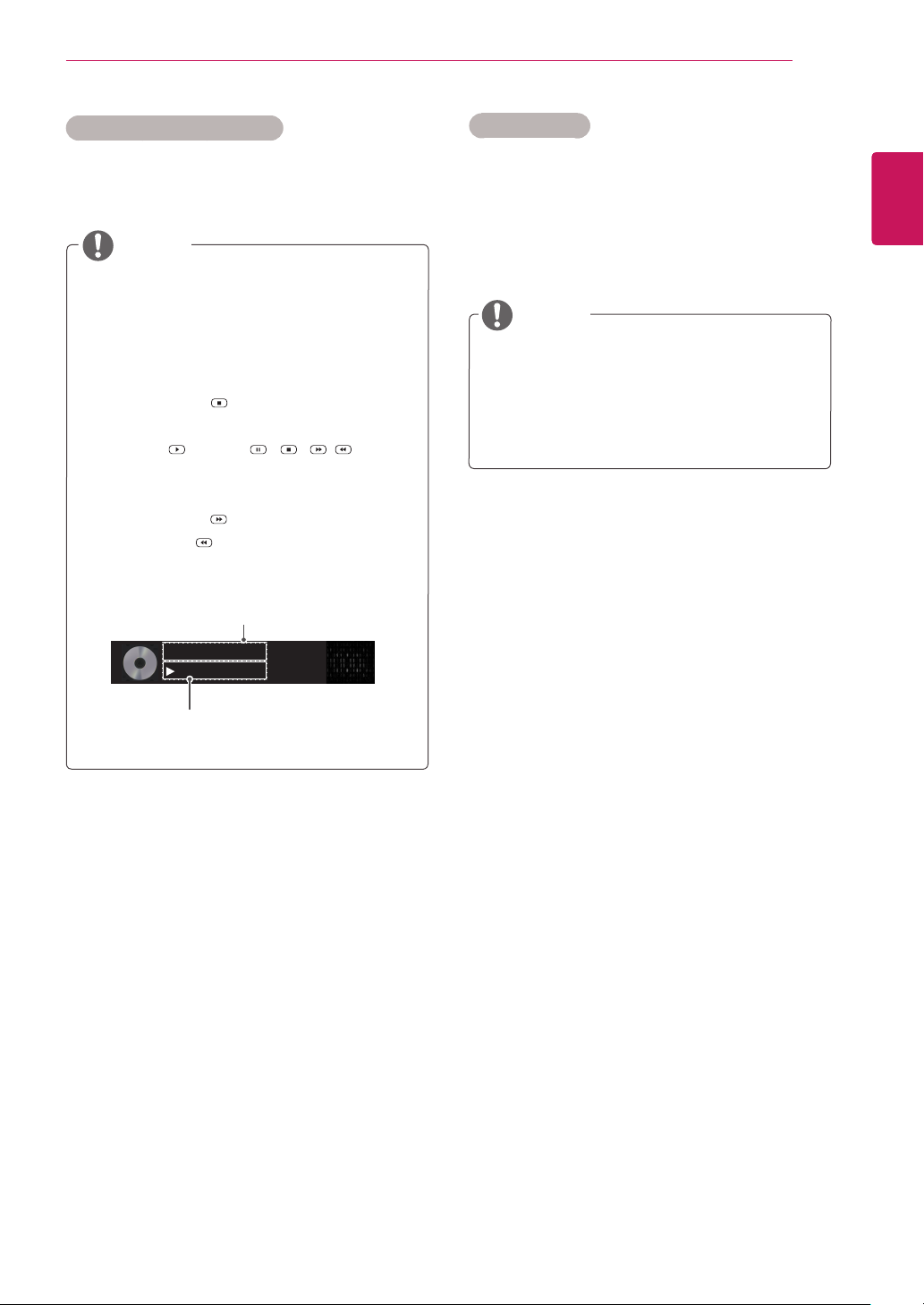
file name
002. B02.mp3
00:31 / 04:04
Music Options
1 Press SETTINGS to access the Pop-Up men-
us.
2 Press the navigation buttons to scroll to Set Au-
dio Play and press OK.
NOTE
y Option values changed in Movie List does
not affect Photo List and Music List.
y Option value changed in Photo List and Mu-
sic List are changed likewise in Photo List
and Music List excluding Movie List.
When you select the Set Audio Play,
1 Press the navigation buttons to scroll to select
the Repeat or Random.
2 Press the navigation buttons to scroll to make
appropriate adjustments.
ENGLISH
ENG
Time elapsed /Duration
Page 38
38
Viewing the Contents List
ENGLISH
ENG
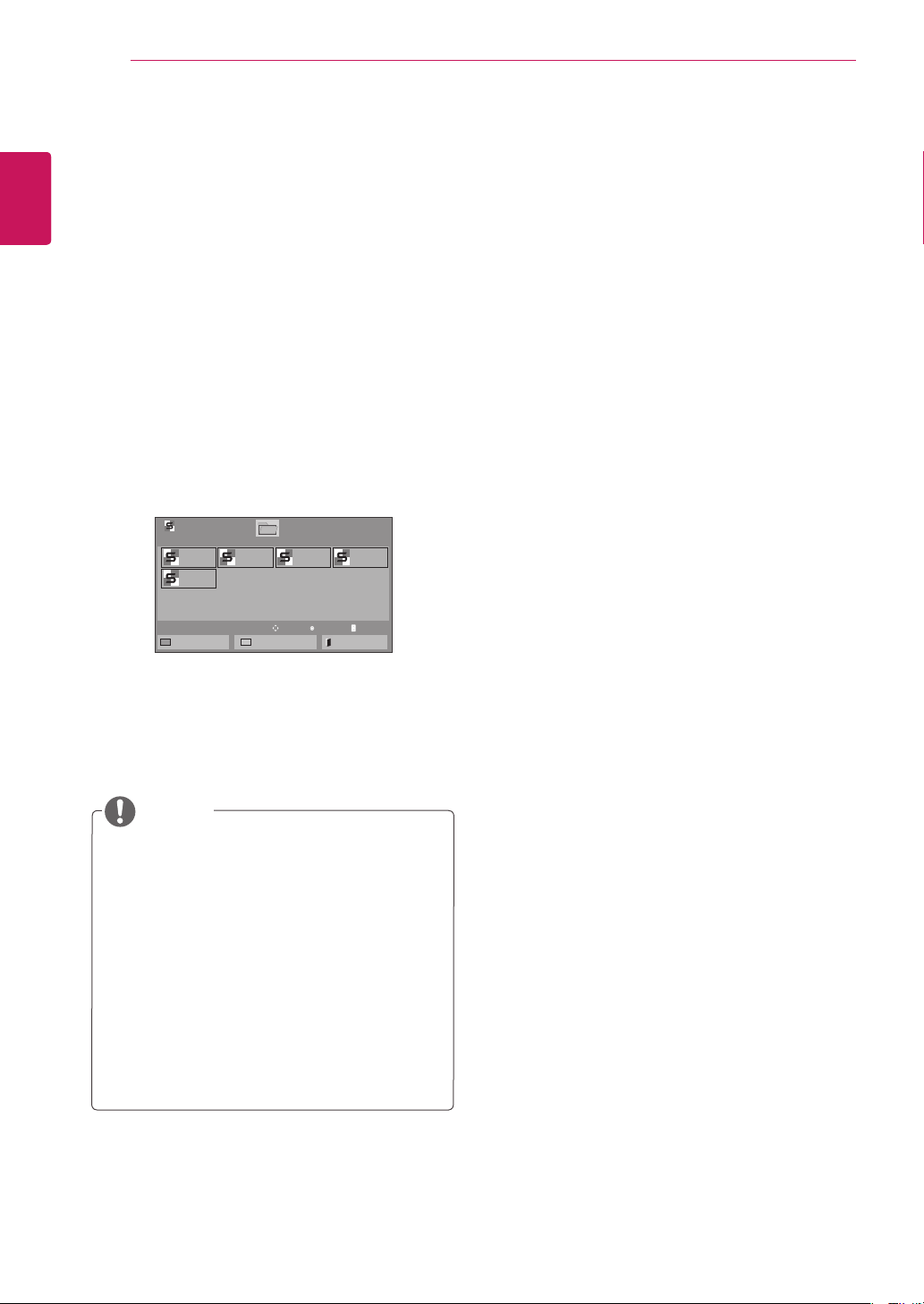
Plays back the stored files using the Export option
in SuperSign Manager.
1 Press the Navigation buttons to scroll to My
2 Press the Navigation buttons to scroll to Con-
3 Press the Navigation buttons to scroll to a
4 Press the Navigation buttons to scroll to a file
ENTERTAINMENT
Media and press OK.
tents List and press OK.
folder you want and press OK.
you want and press OK.
Contents List
USB1 USB Drive
test1.cts
07/01/2011
test5.cts
07/01/2011
To Movie List
test2.cts
07/01/2011
Change Numbers
Page 1/1
Drive1
test3.cts
07/01/2011
Move
Page 1/1
test4.cts
07/01/2011
Play
Page ChangeP
Exit
NOTE
y While playing media files from Contents List,
only the BACK, EXIT or Volume button are
available. Selecting the BACK or EXIT button
stops playing media files and returns to the
screen view mode.
y If there is the AutoPlay folder in the USB
device and its files are in supported formats,
they can be played back automatically when
the USB device is connected to the monitor.
y The function of Contents List may not be
supported depending on the model.
Page 39
ENTERTAINMENT
39
DivX® VOD Guide
DivX® VOD Registration
In order to play purchased or rented DivX® VOD
contents, you should register your device with 10
digit DivX registration code from your device at
www.divx.com/vod.
1 Press SETTINGS to access the main menus.
2 Press the navigation buttons to scroll to MY ME-
DIA and press OK.
3 Press the Blue button.
4 Press the navigation buttons to scroll to DivX
Reg. Code and press OK.
5 View the registration code of your display.
6 When you are finished, press EXIT.
When you return to the previous menu, press
BACK.
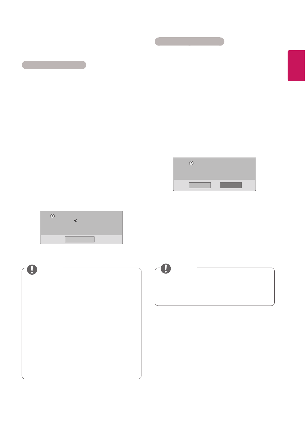
You must register your device to
play DivX protected videos.
Registration code : **********
Register at http://vod.divx.com
DivX® VOD Deregistration
You should deregister your device with 8 digit DivX
deregistration code from your device at www.divx.
com/vod.
1 Press SETTINGS to access the main menus.
2 Press the navigation buttons to scroll to MY ME-
DIA and press OK.
3 Press the Blue button.
4 Press the navigation buttons to scroll to Deacti-
vation and press OK.
5 Press the navigation buttons to select Yes to
confirm.
Deregistration code :
********
Deregister at http://vod.divx.com
Continue with registration?
Yes No
6 When you are finished, press EXIT.
When you return to the previous menu, press
BACK.
ENGLISH
ENG
Close
NOTE
y While you are checking the registration
code, some buttons may not work.
y If you use the DivX registration code of
another device, you cannot play the rented
or purchased DivX file. Make sure to use
the DivX registration code assigned to your
product.
y The video or audio files that are not con-
verted by the standard DivX codec may be
corrupted or not be played.
y The DivX VOD code allows you to activate
up to 6 devices under one account.
NOTE
Once the deregistration is executed, you
y
must register your device again to see
DivX® VOD contents.
Page 40
ENTERTAINMENT
40
Using PIP/PBP
ENGLISH
ENG
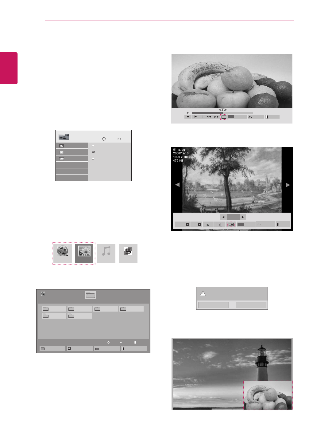
Displays videos or photos stored on a USB device
on a single monitor by dividing it into the main and
sub screens.
1 Press the SETTINGS button to move to
2 Press PIP/PBP to select PIP or PBP and then
3 Select Movie List or Photo List from My
OPTION and press OK.
press OK.
Mode
Position
Size
PIP/PBP
Off
PIP
PBP
Move
Pre.
Media. (With PIP/PBP selected, the Music
List and Contents List are deactivated. The
function of Contents List may not be supported
depending on the model.)
5 Select the PIP or PBP icon from the play list.
Option
MENU
01:02:30 / 02:30:25
Hide
Option
Exit
Hide
MENU
< Movie List >
2/13
Slideshow BGM
< Photo List >
Exit
Movie List Music ListPhoto List Contents List
4 Select a file you want and then press OK.
003
Mark Mode
Page 1/1
Move
004
Play
Exit
Movie List
USB1 USB Drive
001 002
005 006
To Photo list
Drive1
Change Numbers
6 Select either Main or Sub for sound. You must
to select the output sound before running the
PIP or PBP function.
Select the sound path.
Page 1/1
Main Sub
7 The sub screen is displayed on the main
screen.
Page ChangeP
Page 41
CUSTOMIZING SETTINGS
41
CUSTOMIZING SETTINGS
Accessing the Main Menus
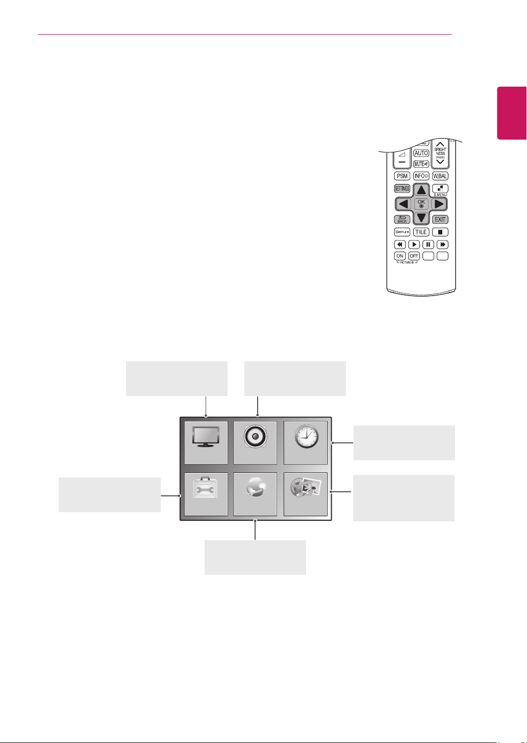
Press
1
Press the navigation buttons to scroll to one of the following menus and
2
Press the navigation buttons to scroll to the setting or option you want
3
When you are finished, press
4
SETTINGS
to access the main menus.
press OK.
and press OK.
EXIT
.
When you return to the previous menu, press
PICTURE
Adjusts the image size,
quality, or effect.
BACK
.
AUDIO
Sets the functions of
AUDIO.
ENGLISH
ENG
OPTION
Sets the functions of
OPTION.
PICTURE
OPTION
NETWORK
Sets the functions of
NETWORK.
AUDIO TIME
NETWORK
TIME
Sets the time, date, or
timer feature.
MY MEDIA
Display and play movie,
MY MEDIA
photo and music content
stored on your USB.
Page 42
CUSTOMIZING SETTINGS
42
ENGLISH
PICTURE Settings
ENG
1
2
3
4
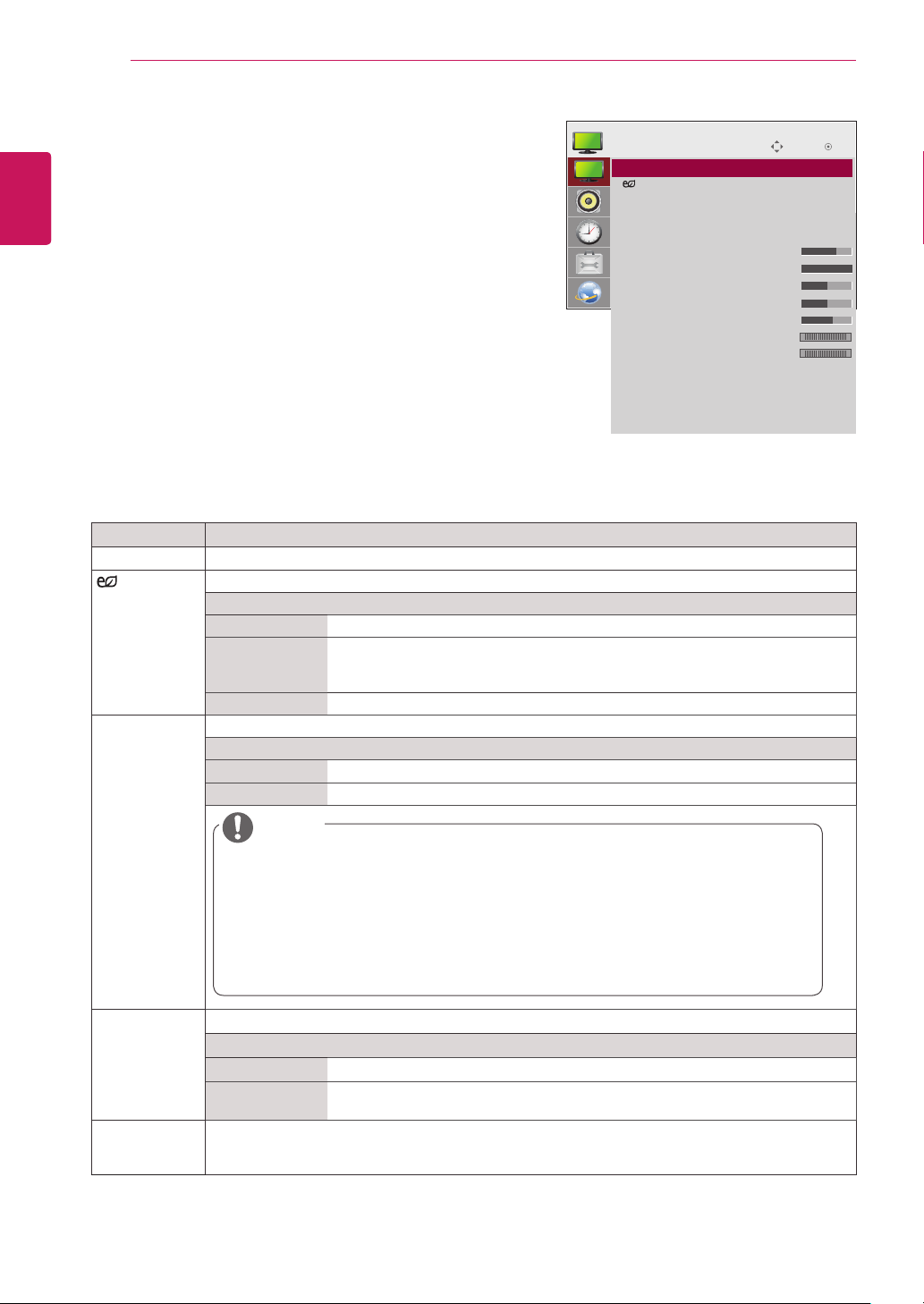
The available picture settings are described in the following:
Press
Press the navigation buttons to scroll to
SETTINGS
to access the main menus.
PICTURE
and
press OK.
Press the navigation buttons to scroll to the setting or
option you want and press OK.
.
BACK
.
- To return to the previous level, press
When you are finished, press
EXIT
When you return to the previous menu, press
BACK
.
Setting Description
Aspect Ratio
Energy Saving
Easy
Brightness
Control
Changes the image size to view images at its optimal size.
Sets to automatically adjust the screen brightness corresponding to the surroundings.
Level
Off
Minimum/
Disables Energy Saving function.
Selects the brightness level of the backlight.
Medium/
Maximum
Screen Off
The screen turns off in 3 seconds.
Adjusts the backlight according to the schedule you set.
Mode
Off
On
Disables Easy Brightness Control.
Enables Easy Brightness Control.
PICTURE
• Aspect Ratio : 16:9
ꔋ
• Energy Saving : Off
• Easy Brightness Control : Off
• Smart Energy Saving : Off
• Picture Mode : Standard
• Backlight 70
• Contrast 100
• Brightness 50
• Sharpness 50
• Color 60
• Tint 0
• Color Temp. 0
• Advanced Control
• Picture Reset
• TruMotion : Low
• Screen
Move
R G
W C
OK
Smart Energy
Saving
Picture Mode
NOTE
Easy Brightness Control is disabled if the current time is not set.
y
If Energy Saving is set to Maximum, Easy Brightness Control is disabled.
y
You can set up to six schedules and they will be sorted in time ascending order.
y
If more than six schedules are added, the latest schedule will be automatically deleted.
y
You can delete a schedule by pressing the OK button.
y
Duplicate schedules are not added, but the backlight value changes.
y
It may not be supported depending on the model.
y
Adjusts the backlight and contrast depending on the screen brightness.
Level
Off
On
Selects one of the preset image or customizes options in each mode for the best Monitor set screen
performance. You are also able to customize advanced options of each mode. The available preset
picture modes vary depending on the monitor set .
Disables the Smart Energy Saving function.
Enables the Smart Energy Saving function to save power consumption as much
as the value set in the smart energy saving rate.
Page 43
Setting Description
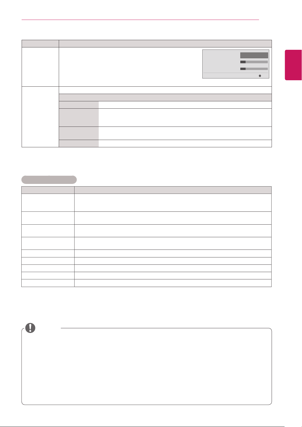
TruMotion
SCREEN
(In RGB
Mode Only)
Corrects images to display smoother motion sequences.
• Low : De-Judder / De-Blur value is set to 3.
• High : De-Judder / De-Blur value is set to 7.
• User : De-Judder / De-Blur can be set manually.
- De-Judder : This function adjusts juddering of
the screen.
- De-Blur : This function adjusts and eliminates blurring of the screen.
Customizes the PC display options in RGB mode.
Option
Resolution
Auto Configure
Position/Size/
Phase
Reset
Selects a proper resolution. See “Customizing PC display options”.
Sets to adjust the screen position, clock, and phase automatically.
The displayed image may be unstable for a few seconds while the configuration is
in progress.
Adjusts the options when the picture is not clear, especially when characters are
shaky, after the auto configuration.
Restores the options to the default setting.
Basic Image Options
CUSTOMIZING SETTINGS
TruMotion
• De-Judder 3
• De-Blur 3
◄
Low
►
43
ENGLISH
ENG
OK
Setting Description
Backlight
Contrast
Brightness
Sharpness
Color
Tint
Color Temp .
Advanced Control
Picture Reset
Adjusts the brightness of the screen by controlling the LCD backlight. If you decrease the
brightness level, the screen becomes darker and the power consumption will be reduced
without any video signal loss.
Increases or decreases the gradient of the video signal. You may use Contrast when the
bright part of the picture is saturated.
Adjusts the base level of the signal in the picture. You may use Brightness when the dark part
of the picture is saturated.
Adjusts the level of crispness in the edges between the light and dark areas of the picture.
The lower the level, the softer the image.
Adjusts intensity of all colors.
Adjusts the balance between red and green levels.
Set to warm to enhance hotter Colors such as red, or set to cool to make picture bluish.
Customizes the advanced options. Refer to the Advanced image options.
Restores the options to the default setting.
NOTE
Picture Mode
If the '
y
' setting in the Picture menu is set to
the subsequent menus will be automatically set.
You cannot adjust
y
When using the Smart Energy Saving function, the screen may look saturated in the white area of a
y
Sharpness, Color
and
Tint
in the RGB/ HDMI-PC/ DVI-PC mode.
still image.
If Energy Saving is set to Minimum, Medium, or Maximum, the Smart Energy Saving function is
y
disabled.
In Vivid mode, the luminance of the backlight is calibrated, so the settings may be different depending
y
on each product.
Vivid, Standard, Cinema, Sport,
or
Game
Page 44
44
ENGLISH
ENG
CUSTOMIZING SETTINGS
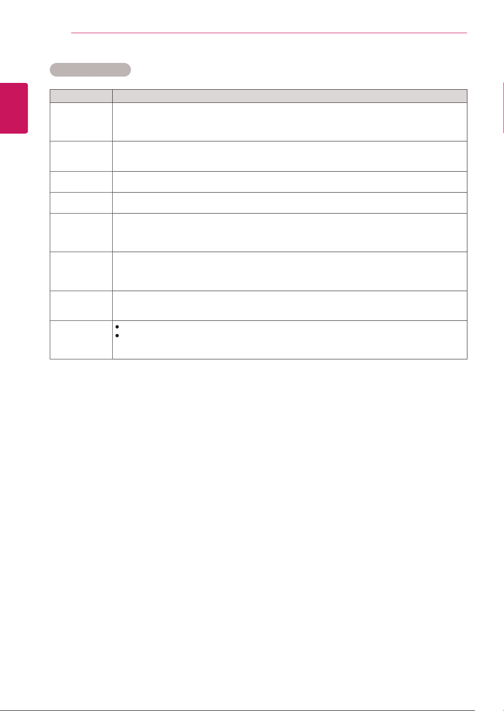
Advanced Control
Setting Description
Dynamic
Contrast
(Off/High/
Medium/Low)
Dynamic Color
(Off/High/Low)
Clear White
(Off/High/Low)
Skin Color
(-5 to 5)
Noise
Reduction
(Off/High/
Medium/Low)
Digital Noise
Reduction
(Off/High/
Medium/Low)
Gamma
(High/Medium/
Low)
Black Level
(High/Low)
Adjusts the contrast to keep it at the best level according to the brightness of the screen. The
picture is improved by making bright parts brighter and dark parts darker. (Function works in the
following mode - AV(CVBS), Component, DP, HDMI, DVI)
Adjusts screen Colors so that they look livelier, richer and clearer. This feature enhances
hue, saturation and luminance so that red, blue, green and white look more vivid. (Function works in
the following mode - AV(CVBS), Component, DP, HDMI, DVI)
Make the white area of screen brighter and more white.
It detects the skin area of video and adjusts it to express a natural skin color.
Reduces screen noise without compromising video quality. (Function works in the following mode -
AV(CVBS), Component, DP, HDMI, DVI)
This option reduces the noise produced while creating digital video signals.
Set your own gamma value. On the monitor, high gamma values display whitish images and low
gamma values display high contrast images.
Low: The picture of the screen gets darker.
High: The picture of the screen gets brighter.
Set black level of the screen to proper level.
(Function works in the following mode - AV(CVBS), Component, DP, HDMI, DVI)
Page 45
CUSTOMIZING SETTINGS
45
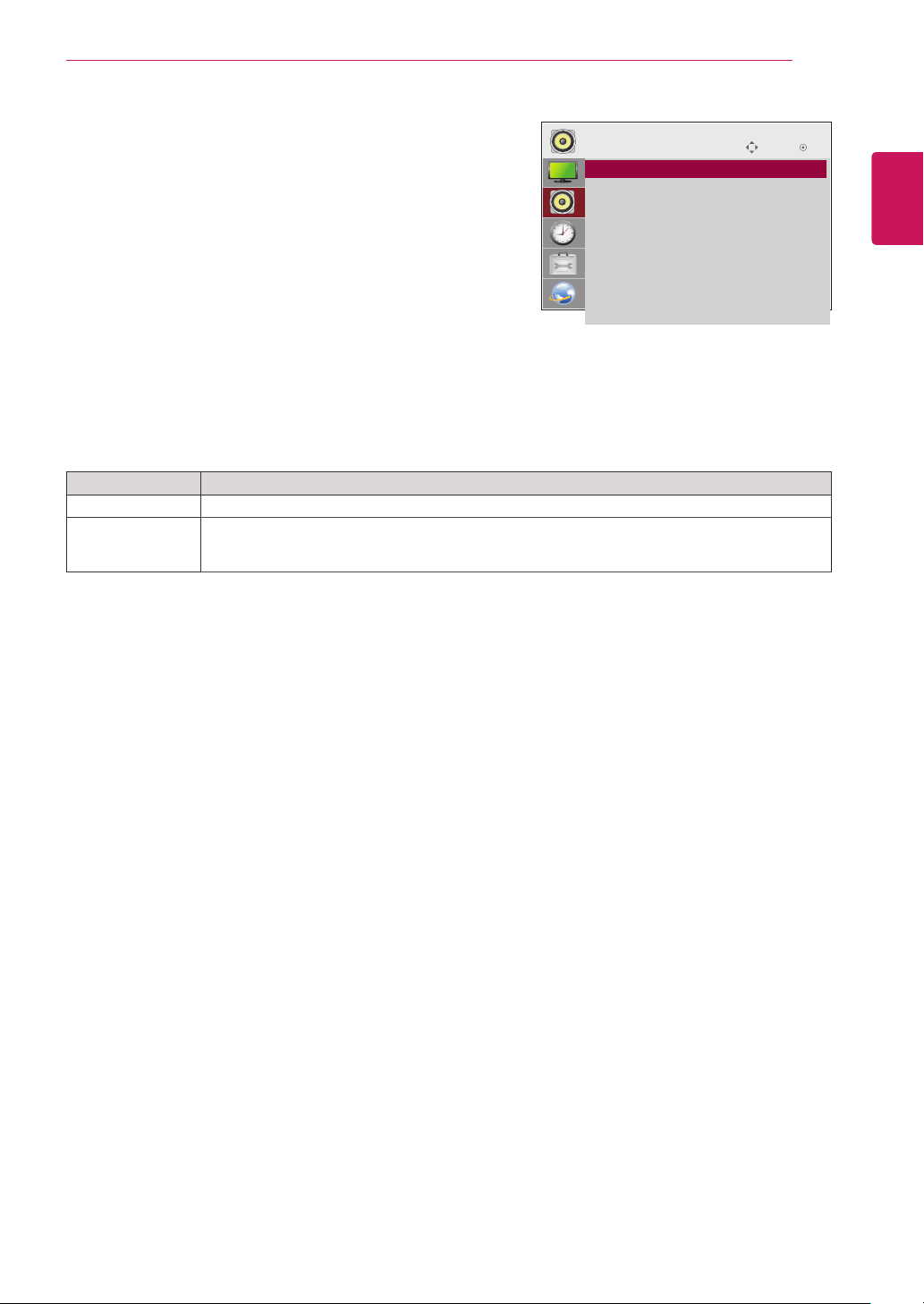
AUDIO Settings
OK
SETTINGS
.
to access the main menus.
AUDIO
and press
option you want and press OK.
- To return to the previous level, press
EXIT
When you return to the previous menu, press
Setting Description
Sets the audio output to mute.
This function is available in HDMI or DisplayPort inputs.
HDMI/DisplayPort
Audio In
: Listen to audio from an external device through the monitor speakers.
BACK
.
.
BACK
: Listen to digital audio through the monitor speakers.
Press
1
Press the navigation buttons to scroll to
2
Press the navigation buttons to scroll to the setting or
3
When you are finished, press
4
The available audio options are described in the following:
Mute
Digital Audio
Input
AUDIO
• Mute : Off
ꔋ
• Digital Audio Input : Audio In
Move OK
ENGLISH
ENG
.
Page 46

CUSTOMIZING SETTINGS
46
TIME Settings
ENGLISH
ENG
1
2
3
4
The available time settings are described in the following:
Press
Press the navigation buttons to scroll to
SETTINGS
to access the main menus.
TIME
and press OK.
Press the navigation buttons to scroll to the setting or option
you want and press OK.
.
BACK
.
BACK
.
- To return to the previous level, press
When you are finished, press
EXIT
When you return to the previous menu, press
Setting Description
Clock
On/Off Time
Sleep Timer
Power on delay
Auto off
Automatic
Standby
Sets the time feature.
Sets the time to turn on or off the monitor set.
Sets the length of time until the monitor set to turns off. When you turn the monitor set off and turn
it on again, the Sleep Timer will be set to off.
When connecting multiple monitors and turning the power on, the monitors are turned on individually
to prevent overload.
If Auto off is active and there is no input signal, the set switches to off mode automatically after 15
minutes.
If you do not use the monitor for more than 4 hours, it will be in standby mode automatically.
TIME
• Clock
ꔋ
• Off Time : Off
• On Time : Off
• Sleep Timer : Off
• Power On Delay : Off
• Auto Off : 15 min.
• Automatic Standby : 4hours
Move
OK
NOTE
Once the on or off time is set, these functions operate daily at the preset time.
y
The scheduled power-off function works properly only when the device time is set correctly.
y
When the scheduled power-on and power-off times are the same, the power-off time has priority over
y
the power-on time if the set is turned on, and vice versa if the set is turned off.
Page 47
CUSTOMIZING SETTINGS
47
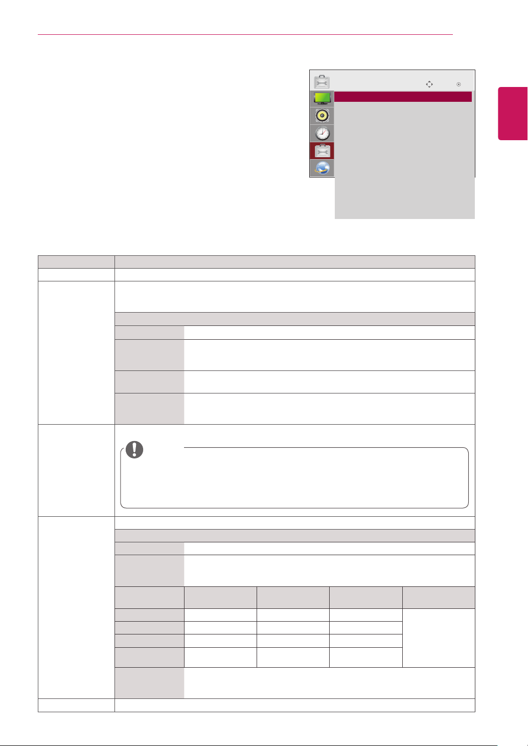
OPTION Settings
OK
SETTINGS
.
to access the main menus.
OPTION
and press
you want and press OK.
- To return to the previous level, press
EXIT
When you return to the previous menu, press
Setting Description
To choose the language in which the control names are displayed.
A frozen or still picture from a PC/Video game displayed on the screen for prolonged periods
could result in a ghost image remaining even when you change the image. Avoid allowing a fixed
image to remain on the screen for a long period of time.
Setting
Normal
Orbiter
Inversion
White Wash
A user can choose to turn the power saving mode on / off.
BACK
.
.
BACK
.
Leave on normal if you don't foresee image burn in being a problem.
May help prevent ghost images. However, it is best not to allow any fixed
image to remain on the screen. To avoid a permanent image on the screen,
the screen will move every 2 minutes.
This fu nction inve rts the p anel color of th e screen. The pan el colo r is
automatically inverted every 30 minutes.
White wash fills the screen with solid white. This helps removes permanent
images burned into the screen. A permanent image may be impossible to clear
entirely with white wash.
Press
1
Press the navigation buttons to scroll to
2
Press the navigation buttons to scroll to the setting or option
3
When you are finished, press
4
The available option settings are described in the following:
Language
ISM Method
DPM Select
OPTION
• Language
ꔋ
• ISM Method : Normal
• DPM Select : On
• Fail Over : Off
• Factory Reset
• Set ID : 1
• Tile Mode
• PIP/PBP
• Fan
• USB Content Recovery : Off
• SIMPLINK
• Product/Service Info.
Move
OK
ENGLISH
ENG
Fail Over
Factory Reset
NOTE
You can set Energy Saving to Off or set the length of time before entering Energy Saving
y
mode to 5 sec./10 sec./15 sec./1 min./3 min./5 min./10 min.
It makes a little difference according to your environment.
y
It may not be supported depending on the model.
y
If there is no input signal, it automatically switches to another input with signal.
Setting
Off
Auto
Current
Input Source
RGB HDMI DVI DP If there is no
DVI HDMI DP RGB
HDMI DVI DP RGB
DP HDMI DVI RGB
Manual
Select this option to return to the default factory settings.
Stops auto switch of the input source.
Attempts to find another input source having video signal according to the
defined input order if no video signal comes from the current input source.
(Refer to the sequence of the table below.)
Attempt 1 Attempt 2 Attempt 3 Attempt 4
signal to switch to,
then the current
The input source changes according to the specified order.
If there is no video signal from the specified input source, then the current
input source remains.
available video
input source
remains.
Page 48

48
ENGLISH
ENG
CUSTOMIZING SETTINGS
Setting Description
Set ID
Tile Mode Tile Mode
PIP/PBP
You can assign a unique Set ID NO (name assignment) to each product when several products
are connected for display. Specify the number (1 - 255, 1 - 1,000 in certain models) using the
button and exit. Use the assigned Set ID to individually control each product using the Product
Control Program.
To use this function
- Must be displayed with various other products.
- Select Tile Mode, set rows and columns, and then enter the tile ID to set the
location.
- Tile Mode: row x column (row = 1-15, column = 1-15).
- 15 x 15 available.
Auto Config.
Position
Size
Natural
Reset
Displays videos or photos stored in the USB device on a single monitor by dividing it into the main
and sub screens.
Option
Mode
Position
Size
Sets to adjust the screen position, clock, and phase automatically.
The displayed image may be unstable for a few seconds while the
configuration is in progress.
Moving the screen position horizontally and vertically.
Adjust the horizontal and vertical size of the screen taking into account the size
of the bezel.
The image is omitted by the distance between the screens to be naturally
shown.
Function to initialize and release Tile.
All Tile setting are released when selecting Tile recall and the screen returns to
Full screen.
Natural
*
Sets the type of secondary screen.
OFF
*
PIP (Picture In Picture)
*
PBP (Picture By Picture)
*
screen.
Adjusts the position of the sub screen (top left, bottom left, top right, bottom
right)
The default value is the bottom right.
Adjusts the size of the sub screen (Size 0 to 10).
The default size of PIP (Size: 0) is 480x270; the maximum size 10 is 960x540.
is not initialized.
: Disables the secondary screen.
: Displays the secondary screen in the main screen.
: Displays the secondary screen next to the main
NOTE
The Position and Size options are enabled only in PIP mode.
y
Page 49
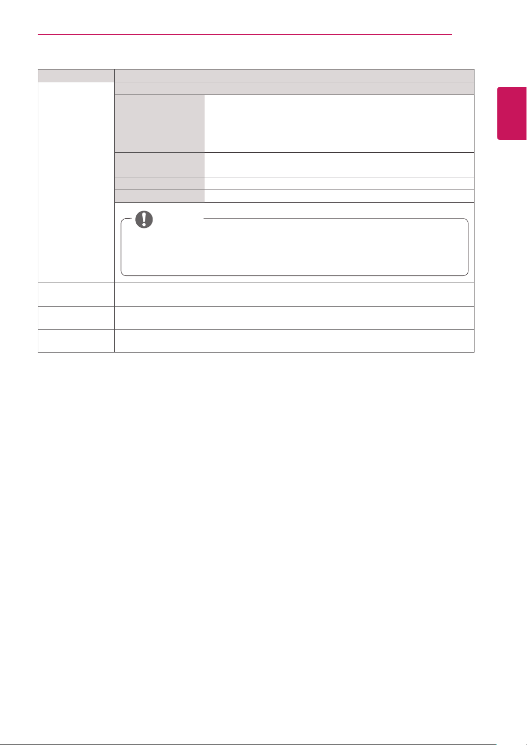
Setting Description
Fan
(Only for 55LV77A
model)
Setting
Mode
Hysteresis
Set Temperature
Current Temperature
This option indicates the monitor's internal temperature and controls the
fan.
• Auto: Switches the fan on and off according to the set temperature.
• On: The fan is always switched on.
• Manual: Switches the fan on and off according to user settings.
The difference in temperature between when the fan is switched on and
when it is off.
Set the temperature at which the fan is switched on.
Current temperature inside the set.
NOTE
We recommend that you use the Auto mode to prevent any malfunctions resulting from
y
incorrect fan settings.
If the interior temperature of the set exceeds 80°C, the set will be turned off automatically
y
for safety reasons.
CUSTOMIZING SETTINGS
49
ENGLISH
ENG
USB Content
Recovery
SIMPLINK
Product/Service
Info.
Replays the content in a USB when the power is back on if it is turned off during playing a content.
(This function operates the same when a USB is disconnected and connected again.)
Allows you to control various multimedia devices simply by using the remote control through the
SimpLink menu. (It may not be supported depending on the model.)
Displays the model name, software version, serial number, IP address, MAC address, and home
page.
Page 50
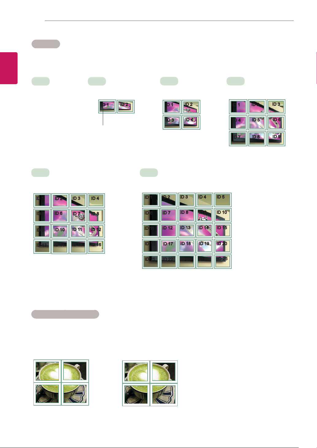
50
ENGLISH
ENG
This monitor can be tiled with additional monitors to create a large tiled display.
CUSTOMIZING SETTINGS
Tile Mode
Off
When the Tile Mode
option is disabled
4X4
When using 16 monitors
ID 1
ID 5
ID 9
ID 13
ID 2
ID 6
ID 10
ID 14
ID 3
ID 7
ID 11
ID 15
1X2
When using 2 monitors
ID 1
ID 2
Tile ID
ID 4
ID 8
ID 12
ID 16
2X2
When using 4 monitors
ID 1
ID 3
ID 2
ID 4
5X5
When using 25 monitors
ID 3
ID 2
ID 1
ID 8
ID 7
ID 6
ID 13
ID 12
ID 11
ID 17
ID 22
ID 18
ID 23
ID 16
ID 21
ID 4 ID 5
ID 9 ID 10
ID 14 ID 15
ID 19
ID 20
ID 24
ID 25
3X3
When using 9 monitors
ID 1
ID 4
ID 7
ID 2
ID 5
ID 8
ID 3
ID 6
ID 9
Tile Mode - Natural mode
When active, the part of the image that would normally be displayed in the gap between the monitors is
omitted.
Before After
Page 51
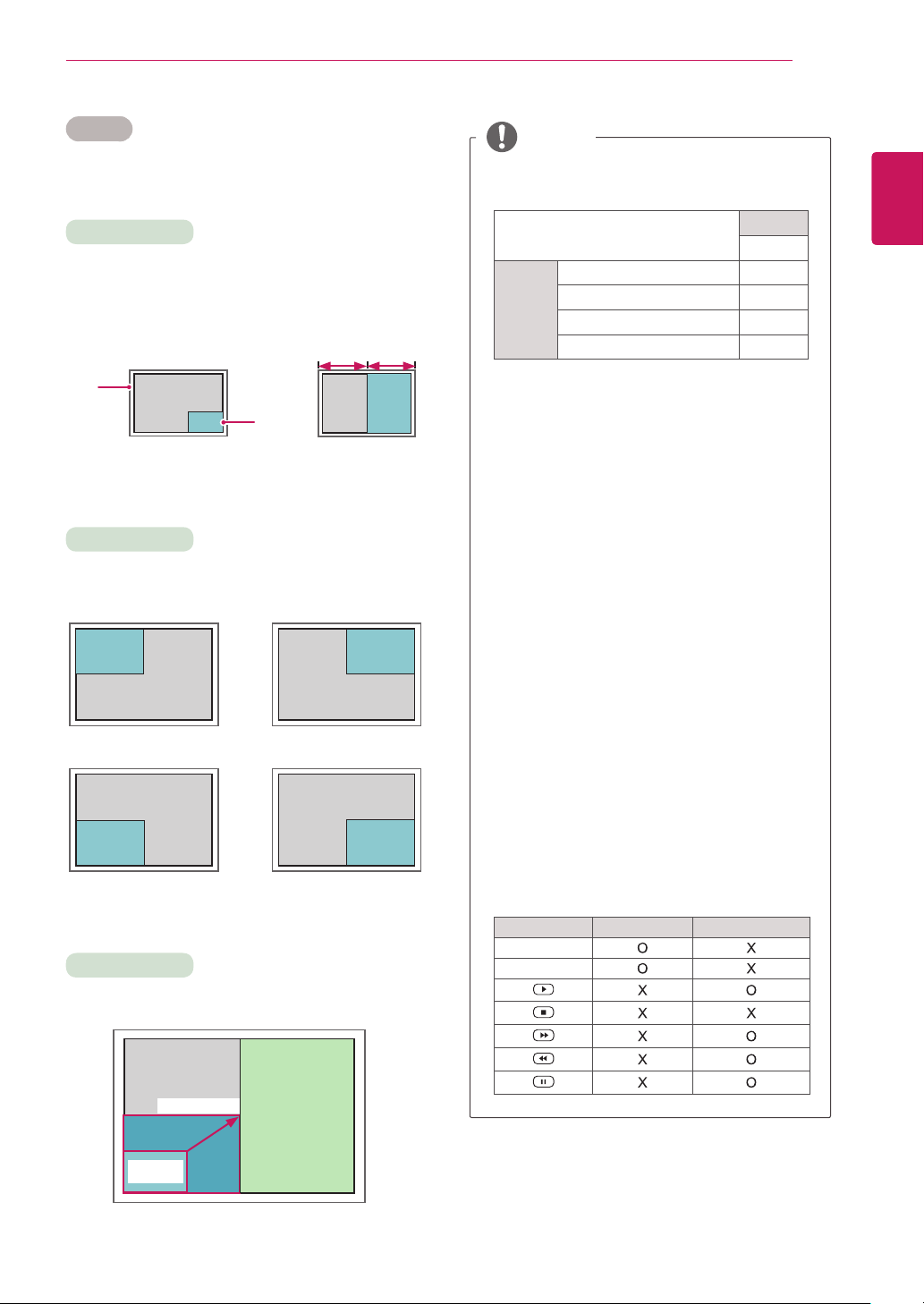
CUSTOMIZING SETTINGS
51
PIP/PBP
Displays videos or photos stored in the USB
device on a single monitor by dividing it into the
main and sub screens.
Mode
*PIP (Picture In Picture): Displays the sub screen
in the main screen.
*PBP (Picture By Picture): Displays the sub
screen next to the main screen.
Main
Screen
PIP
Sub
Screen
PBP
Position
Adjusts the position of the subscreen (top left,
bottom left, top right, bottom right)
top left top right
bottom left bottom right
Size
Adjusts the size of the subscreen (Size 0-10).
NOTE
The subscreen is only supported when using
y
the USB device.
Sub
USB
Component O
Main
You can only change the size and position in
y
PIP mode.
With PBP selected, the Aspect Ratio option
y
in the PICTURE menu is disabled (Fixed as
16:9).
While running the PIP/PBP function, the Tile
y
Mode function does not work.
You must select the output sound before
y
running the PIP or PBP functions. (Select
either main or sub.)
If you fail to select main or sub from the
y
sound selection box, and if the OSD
disappears after either a period of time or
when the Exit or Back key is pressed, the
PIP/PBP subscreen is not activated.
You cannot change the sound while running
y
the PIP or PBP functions. If you want to
change the sound, please restart PIP/PBP.
The picture quality of the subscreen is set
y
according to the values selected in the main
menu, not the USB device.
If you play videos you selected in PIP/PBP
y
mode, the videos will play back repeately in
succession.
The buttons below work in PIP mode.
y
RGB O
HDMI/DVI-D/Display Port O
AV X
Button Photo Movie
◄
►
ENGLISH
ENG
10 : 960x540
PIP
0 :
480x270
< 1920x1080 >
PBP
960x1080
Page 52
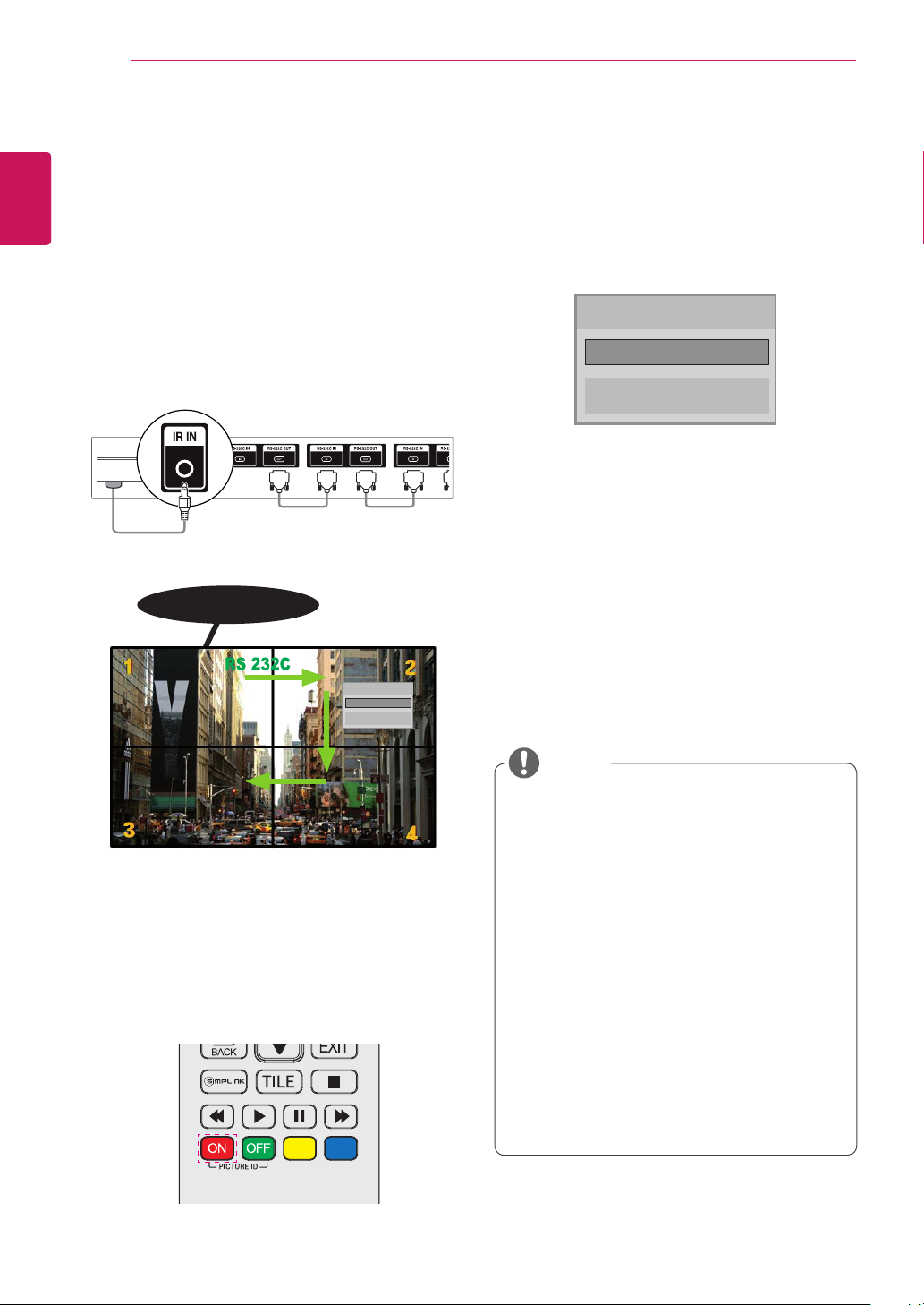
CUSTOMIZING SETTINGS
AUDIO
(RGB/DVI)
REMOTE
CONTROL IN
RS-232C OUT
RS-232C IN
RS-232C OUT
RS-232C IN
RS-232C OUT
RS-232C IN
52
ENGLISH
Picture ID
ENG
Picture ID is used to change the settings of a
specific display using a single IR receiver for
multi-vision. The set receiving the IR signal
communicates with another set via an RS-232C
connection. Each set is identified by a Set ID. If
you assign the Picture ID using the remote control,
only displays with the same Picture ID and Set ID
can be controlled remotely.
IR Receiver
Picture ID
◄ Off ►
Close
2 To change the Picture ID, press the ON button,
or the left and right arrow buttons continuously.
Assign the ID you want.
Picture ID
◄ Off ►
Close
If you assign the Set ID to each set with
y
multi-vision, and then assign the Picture ID
using the red button on the remote control,
the key command is displayed for the set
with the same Set ID and Picture ID. A set
with different Set IDs and Picture IDs cannot
be controlled by IR signals.
The maximum value of the Picture ID can be
y
set in the Total Set ID menu.
Please refer to the Installation Manual for
y
more information on Total Set ID assignment.
2X2 Multi-Vision (Total Set ID: 4)
Set IDs are assigned as shown in the picture.
1 Press the red ON button on the remote control
to assign the Picture ID.
NOTE
For example, if the Picture ID is assigned to
y
2, the upper right display (Set ID: 2) can be
controlled by IR signals.
For each set, you can change the settings
y
for the PICTURE, AUDIO, TIME, NETWORK
and MY MEDIA menus or the hot keys on the
remote control.
If you press the green OFF button for Picture
y
IDs, the Picture IDs for all sets are turned off.
If you then press any button on the remote
control, all sets will start working again.
Picture ID will be disabled while using the
y
MY MEDIA menu.
If Picture ID is set to Off, holding buttons
y
on the remote control will execute only one
action at a time.
Page 53
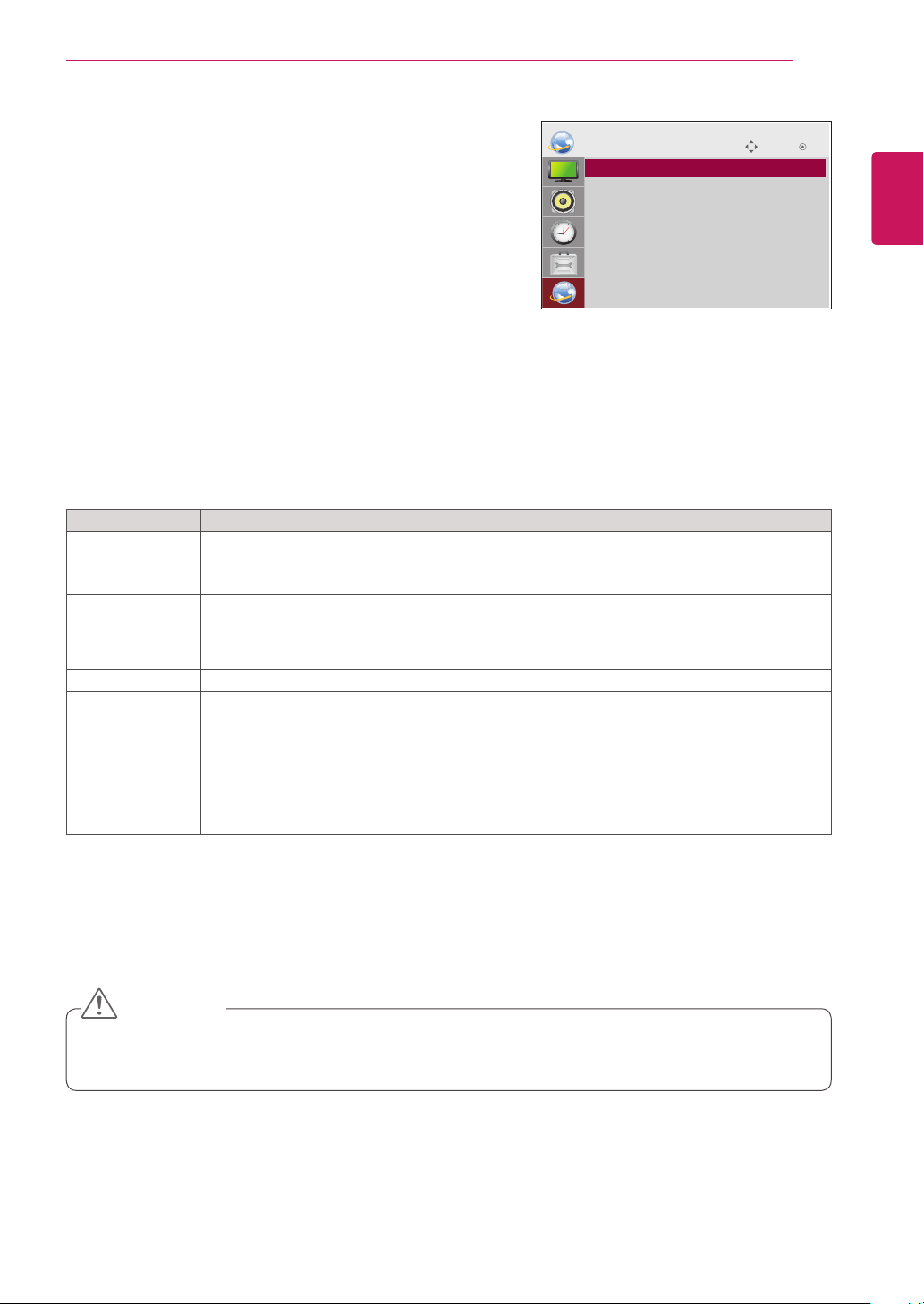
CUSTOMIZING SETTINGS
53
NETWORK Settings
Press
1
Press the navigation buttons to scroll to
2
Press the navigation buttons to scroll to the setting or option
3
When you are finished, press
4
The available option settings are described in the following:
Player Name
Setting
Network Setting
Network Status
Server IP Setting
Server IP Status
SETTINGS
to access the main menus.
NETWORK
and
press OK.
you want and press OK.
.
BACK
.
BACK
.
- To return to the previous level, press
EXIT
When you return to the previous menu, press
Setting Description
Sets the player name used in SuperSign Manager.(Up to 20 characters)
Configure the network settings.
Display the network status.
- Internet is connected : Extermally connected
- Network is connected : Only internally connected
- Not connected : When there is no network connection
Sets the IP address of the computer (server) on which SuperSign Manager is installed.
Displays the connection status with the server.
- Not connected : When there is no network connection with SuperSign server
- Waiting for approval : When network connection with SuperSign server has been made, but
access to server has not been approved by the server
- Rejected : When network connection with SuperSign server has been made, but access to
server has been rejected by the server
- Internet is connected : When network connection with SuperSign server has been made and
access to server has also been approved by the server
NETWORK
• Player Name Setting
ꔋ
• Network Setting : None
• Network Status : Not connected
• Server IP Setting
• Server IP Status : Not connected
Move OK
ENGLISH
ENG
CAUTION
When setting the Player Name Setting, input delay may occur if you press the buttons on the remote
y
control continuously.
Page 54
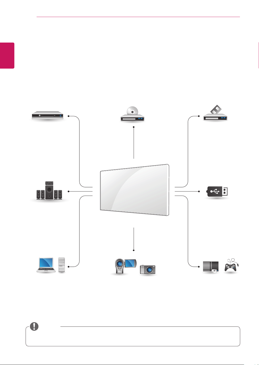
MAKING CONNECTIONS
54
ENGLISH
MAKING CONNECTIONS
ENG
Connect various external devices to the ports on the monitor set’s back panel.
1
2
3
HDMI
DVI
AV
Component
Find an external device you want to connect to your monitor set shown on the following illustration.
Check the connection type of the external device.
Go to the appropriate illustration and check the connection details.
HD Receiver DVD VCR
HDMI
DVI
AV
Component
Speaker
AV
Component
Memory storage
USB
PC Camcorder/ Camera Gaming device
HDMI
DVI
RGB
LAN
Display Port
HDMI
DVI
AV
Component
HDMI
AV
Component
NOTE
If you connect a gaming device to the monitor set, use the cable supplied with the gaming device.
y
Page 55
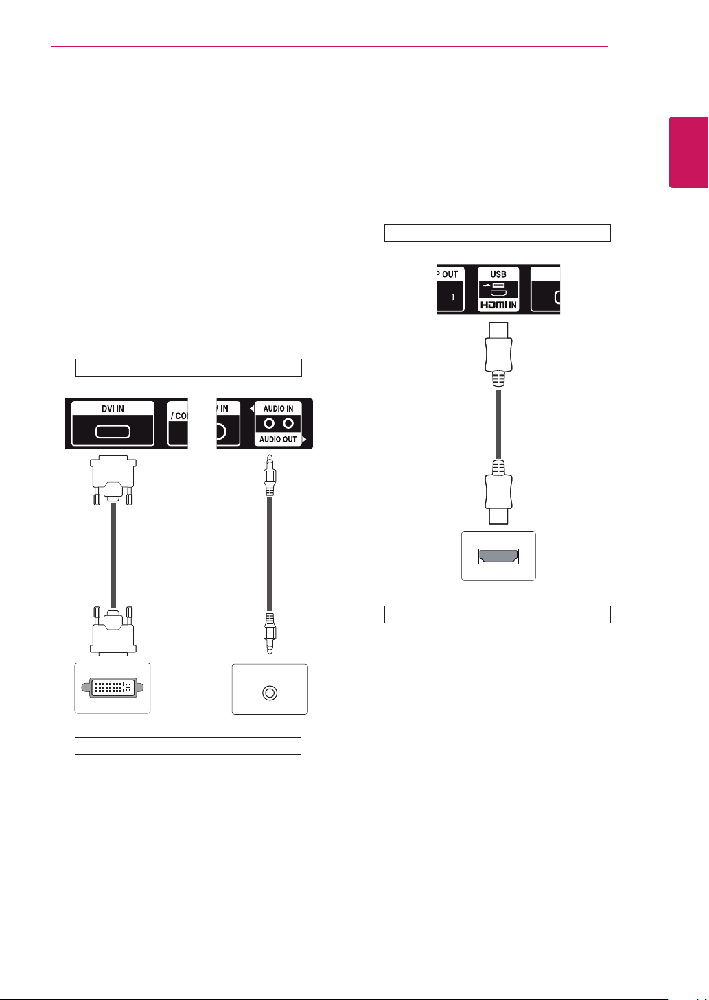
MAKING CONNECTIONS
55
External Device Connection
Connect a HD receiver, DVD, or VCR player to the
monitor set and select an appropriate input mode.
DVI Connection
Transmits the digital video signal from an external
device to the monitor set. Connect the external
device and the monitor set with the DVI cable as
shown in the following illustration. To transmit an
audio signal, connect an optional audio cable.
Back of the product.
HDMI Connection
Transmits the digital video and audio signals from
an external device to the monitor set. Connect the
external device and the monitor set with the HDMI
cable as shown on the following illustration.
Back of the product.
(not included)
ENGLISH
ENG
(not
included)
(not included)
External device
External device
Page 56
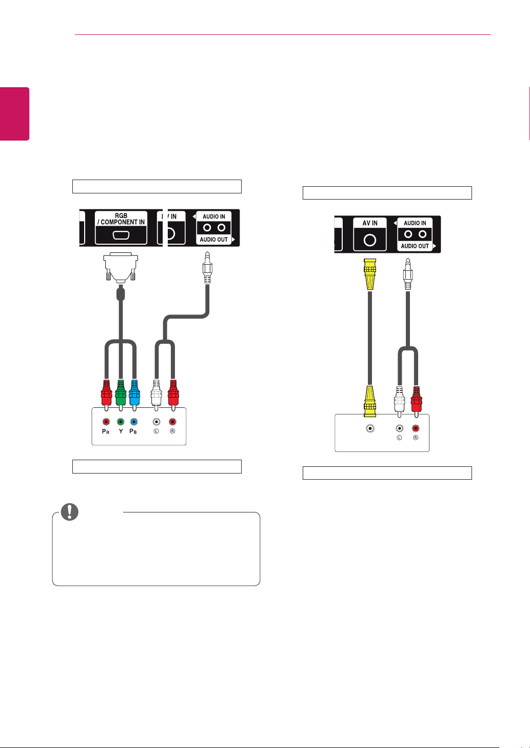
MAKING CONNECTIONS
VIDEO OUT
AUDIO IN
56
Component Connection
ENGLISH
ENG
Transmits the analog video and audio signals from
an external device to the monitor set. Connect
the external device and the monitor set with the
RGB-Component cable as shown in the following
illustration.
Back of the product.
(not included) (not included)
AV(CVBS) Connection
Transmits the analog video and audio signals from
an external device to the monitor set. Connect
the external device and the monitor set with
the composite cable as shown in the following
illustration.
Back of the product.
(not included)(not included)
External device
NOTE
When connecting to the component port
y
using the shared interface, the port must
match up to the input source. Otherwise,
noise may occur.
VIDEO OUT
External device
Page 57
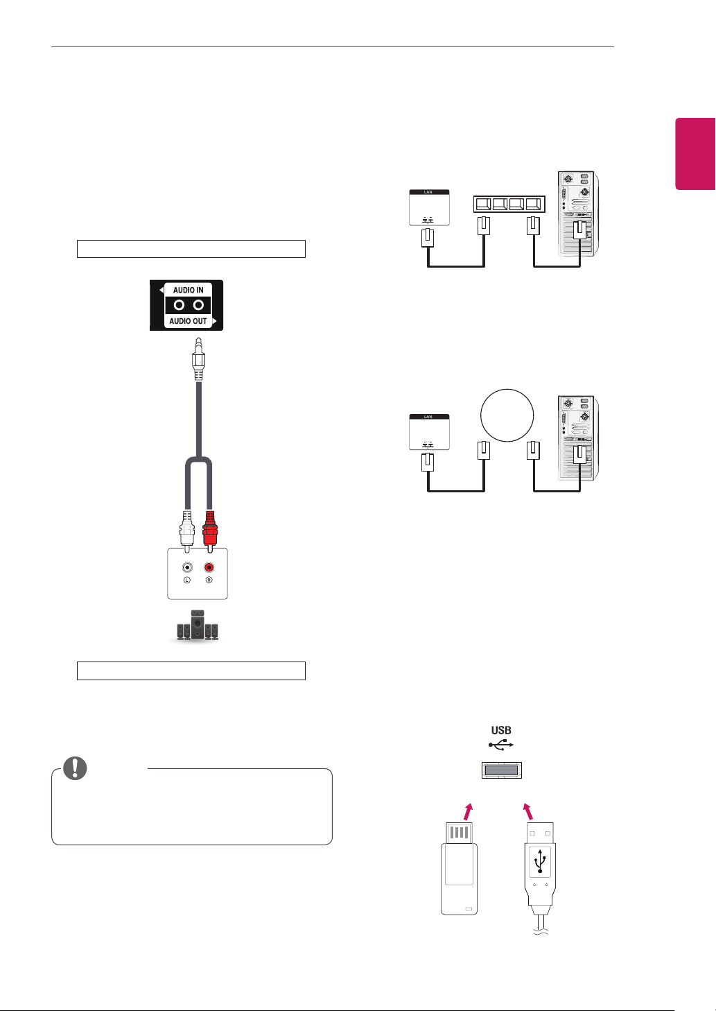
MAKING CONNECTIONS
Network
VIDEO OUT
57
Audio Connection
An analog/digital audio signal is sent from the
monitor to an external device.
Connect the external device to the monitor by
using the audio cable as shown in the following
illustration.
Back of the product.
(not included)
Connecting to the LAN
Using a router (Switch)
A
LAN
Monitor Set
Using the Internet.
B
LAN
Monitor Set
Switch
PC
PC
ENGLISH
ENG
AUDIO IN
External device
NOTE
When connecting an external audio device,
y
use a device with audio amplifier.
Connecting to a USB
Connect a USB storage device such as s USB
flash memory, external hard drive, MP3 player, or
a USB memory card reader to the monitor set and
access the USB menu to use various multimedia
files.
or
Page 58
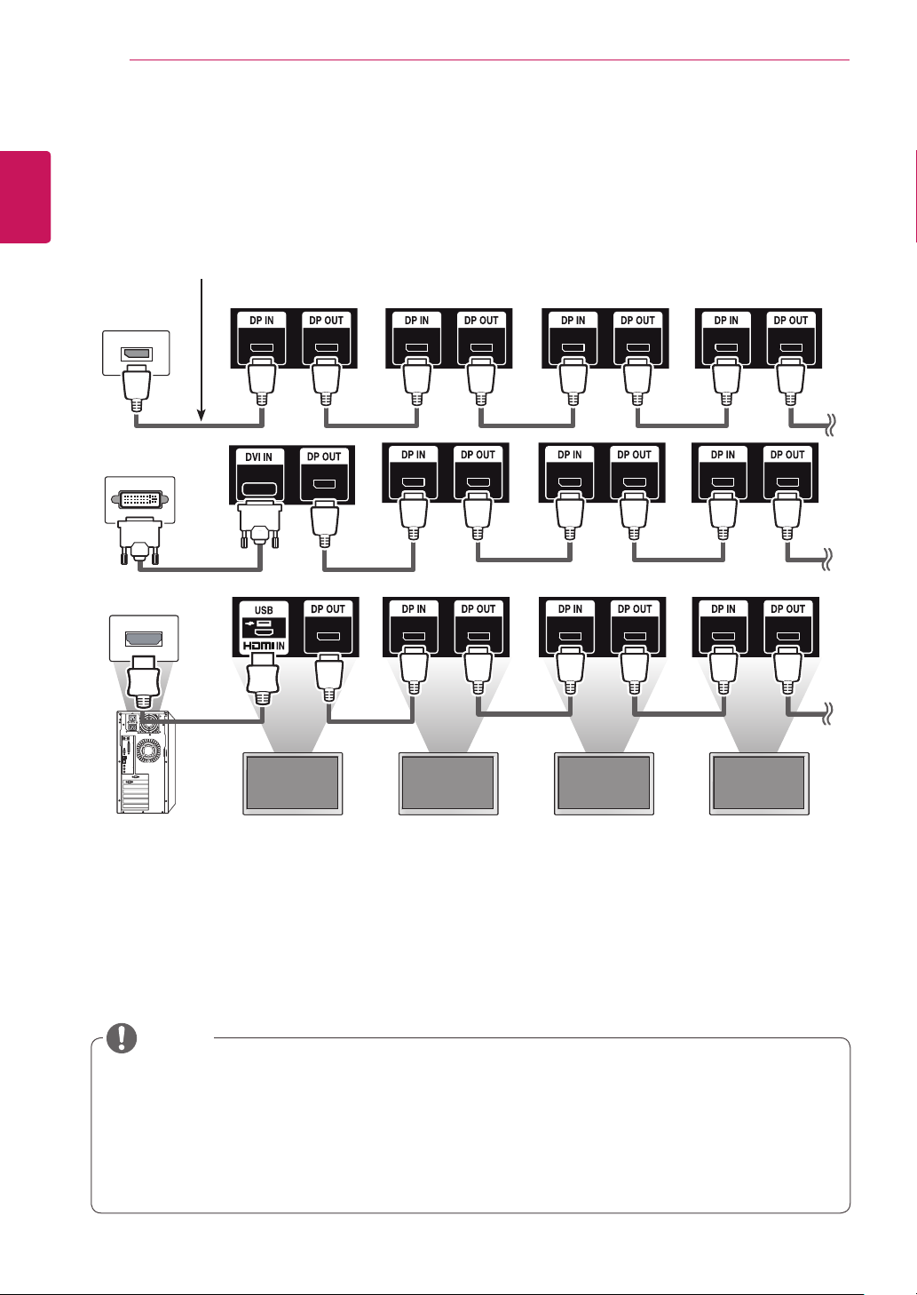
MAKING CONNECTIONS
58
ENGLISH
Daisy Chain Monitors
ENG
To use different products connected to each other, connect one end of the signal input cable (DP Cable) to
the DP Out connector of Monitor 1 and connect the other end to the DP In connector of the other product.
DP Cable
Use the cable provided with the product or use a DisplayPort certified cable version 1.1a or higher.
Monitor 1 Monitor 2 Monitor 3 Monitor 4
NOTE
If the signal is stable and there is no cable loss, in general, up to 100 monitors can be connected via
y
the DP Out port (at the recommended resolution). If you want to connect more than this number of
monitors, it is recommended to use a distributor.
If you set the tile mode using DVI or HDMI, you will not be able to watch HDCP-encrypted content.
y
If the signal cable between the product and your PC is too long, make sure to use the Booster or
y
optical cable.
Page 59

TROUBLESHOOTING
Using the Multi Display Mode function
Multi Display Mode
The
Single Stream Transport) or multi-mode (MST: Multi Stream Transport) through DP Out.
- This function can be configured in the
Installation Menu manual.)
- If it is On, the image of each display is displayed in multi-mode.
Off
- If it is
- The multi-mode is available in a PC supporting DisplayPort 1.2.
- Multi-mode can connect up to only four monitors. (at the recommended resolution.)
- When this function is used, your monitor may not work properly depending on the video card. Reboot
the PC after setting the function to Off for stable screen output when not in use.
- In case of using DVI/HDMI Input to DP Daisy Chain, please set 'Multi Display mode function' to off.
, the image of each display is displayed in single mode.
function displays a video signal received from DP In either in single mode (SST:
Installation Menu
(For more information, refer to the
59
ENGLISH
ENG
Page 60
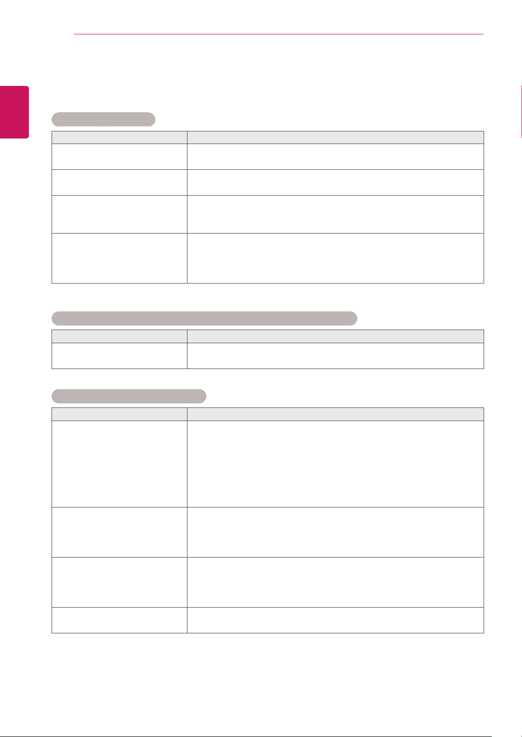
TROUBLESHOOTING
60
ENGLISH
TROUBLESHOOTING
ENG
No image is displayed.
Problem Resolution
Is the product power cord
connected?
Power is on, but the screen
appears extremely dark.
Does the 'Invalid Format'
message appear?
Does the 'No signal' message
appear?
'Unknown Product' message appears when the product is connected.
Problem Resolution
Did you install the driver? y See if the plug&play function is supported by referring to the video
y See if the power cord is properly connected to the outlet.
y Adjust brightness and contrast again.
y Backlight may need repair.
y The signal from the PC (video card) is out of the vertical or horizontal
frequency range of the product. Adjust the frequency range by
referring to the Specifications in this manual.
y The signal cable between PC and product is not connected. Check
the signal cable.
y Press the 'INPUT' menu in the remote Control to check the input
signal.
card user manual.
The screen image looks abnormal.
Problem Resolution
Is the screen position wrong? yD-Sub analog signal - Press the "AUTO" button in the remote control
to automatically select the optimal screen status that fits into the
current mode. If adjustment is not satisfactory, select [PICTURE] [Screen] - [Position] in OSD menu.
ySee if the video card resolution and frequency are supported by the
product. If the frequency is out of range, set to the recommended
resolution in the Control Panel "Display" Setting menu.
Do thin lines appear on the
background screen?
Horizontal noise appears or the
characters look blurred.
The screen is displayed
abnormally.
yD-Sub analog signal - Press the "AUTO" button in the remote control
to automatically select an optimal screen status that fits into the
current mode. If adjustment is not satisfactory, select [PICTURE] [Screen] - [Size] in OSD menu.
yD-Sub analog signal - Press the "AUTO" button in the remote control
to automatically select an optimal screen status that fits into the
current mode. If adjustment is not satisfactory, select [PICTURE] [Screen] - [Phase] in OSD menu.
y The proper input signal is not connected to the signal port. Connect
the signal cable that matches with the source input signal.
Page 61
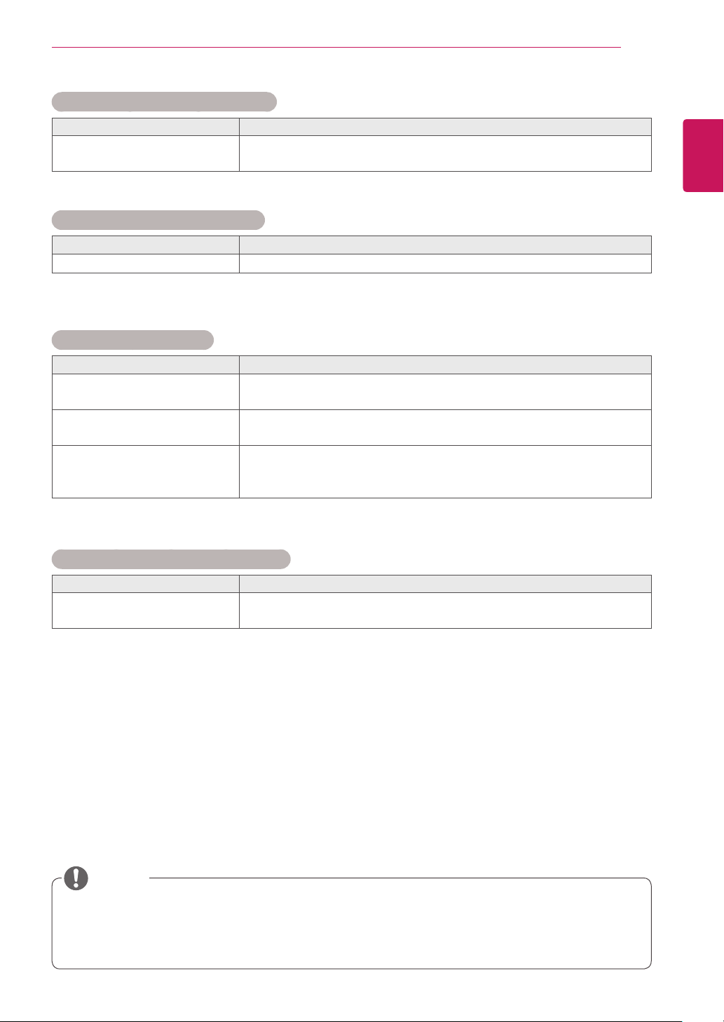
After-image appears on the product.
Problem Resolution
After-image appears when the
product is turned off.
The audio function does not work.
Problem Resolution
No sound? ySee if the audio cable is connected properly.
Screen color is abnormal.
Problem Resolution
Screen has poor color resolution
(16 colors).
Screen color is unstable or
mono-colored.
Do black spots appear on the
screen?
yIf you use a fixed image for a long time, the pixels may be damaged
quickly. Use the screen-saver function.
y Set the number of colors to more than 24 bits (true color) Select
Control Panel - Display - Settings - Color Table menu in Windows.
yCheck the connection status of the signal cable. Or, re-insert the PC
video card.
y Several pixels (red, green, white, or black color) may appear on the
screen, which can be attributable to the unique characteristics of the
LCD panel. It is not a malfunction of the LCD.
TROUBLESHOOTING
61
ENGLISH
ENG
The operation does not work normally.
Problem Resolution
The power suddenly turned off. yIs the sleep timer set?
y Check the power control settings. Power interrupted.
NOTE
The software version can be updated for improvement in performance. Customer needs to ensure
y
the compatibility of customer’s equipment with LGE software. If needed, please consult with LGE and
upload revised software version to the product according to the guidance provided by LGE.
Page 62

SPECIFICATIONS
62
ENGLISH
SPECIFICATIONS
ENG
LCD Panel Screen Type 1387.80 mm Wide TFT (Thin Film Transistor)
LCD (Liquid Crystal Display) Panel.
Visible diagonal size : 1387.80 mm
Pixel Pitch 0.630 mm (H) x 0.630 mm (V)
Video Signal Max. Resolution 1920 x 1080 @ 60 Hz
- It may not be supported depending on the OS or video
card type.
Recommended Resolution 1920 x 1080 @ 60 Hz
- It may not be supported depending on the OS or video
card type.
Horizontal Frequency RGB : 30 kHz to 83 kHz
HDMI/DVI/DP : 30 kHz to 83 kHz
Vertical Frequency RGB : 50 Hz to 75 Hz
HDMI/DVI/DP : 56 Hz to 60 Hz
Synchronization Type Separate Sync, Digital
Input Connector 15pin D-Sub(RGB/Component), DVI/HDMI/DP(Digital),
AV(CVBS), IR, USB, RS-232C, LAN
- You can use the Component output if you connect a 15pin D-Sub conversion cable to the RGB connector.
Power Power rating
55LV75A AC 100-240 V~, 50 / 60 Hz 2.1 A
AC 100-240 V~, 50 / 60 Hz 3.1 A
Smart Energy Saving Mode : 90 W Typ.
Off Mode : ≤ 0.5 W
Sleep Mode : ≤ 0.7 W
On Mode : 230 W Typ. 290 W Max
Smart Energy Saving Mode : 130 W Typ.
Off Mode : ≤ 0.5 W
Sleep Mode : ≤ 0.7 W
* Wall Bracket available VESA
600 x 400
D
Dimensions
(Width x Height x
Depth) / Weight
55LV77A
Power Consumption
55LV75A On Mode : 160 W Typ. 200 W Max
55LV77A
H
W
1213.4 mm x 684.2 mm x 88.5 mm / 23 kg
Environmental
conditions
Product specifications shown above may be changed without prior notice due to upgrade of product
functions.
Operating Temperature
Operating Humidity
Storage Temperature
Storage Humidity
0 °C to 40 °C
10 % to 80 %
-20 °C to 60 °C
5 % to 95 %
Page 63
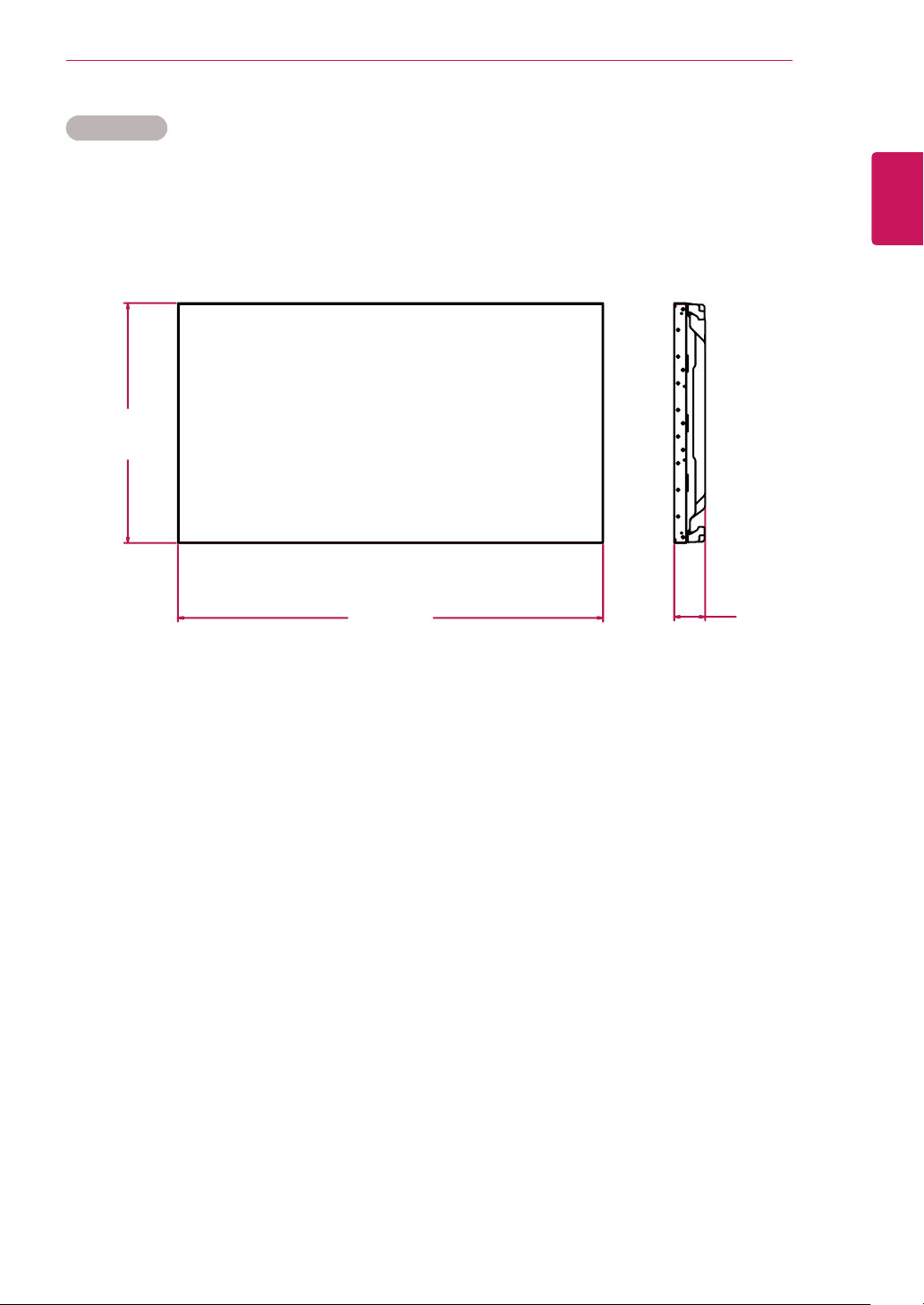
Dimensions
The illustrations in this manual may differ from the actual product and accessories.
Please see the Mounting on a Wall section for sizes of screws. ( See p.9 )
684.2
SPECIFICATIONS
(Unit : mm)
63
ENGLISH
ENG
1213.4
Product specifications shown above may be changed without prior notice due to upgrade of product
functions.
88.5
Page 64
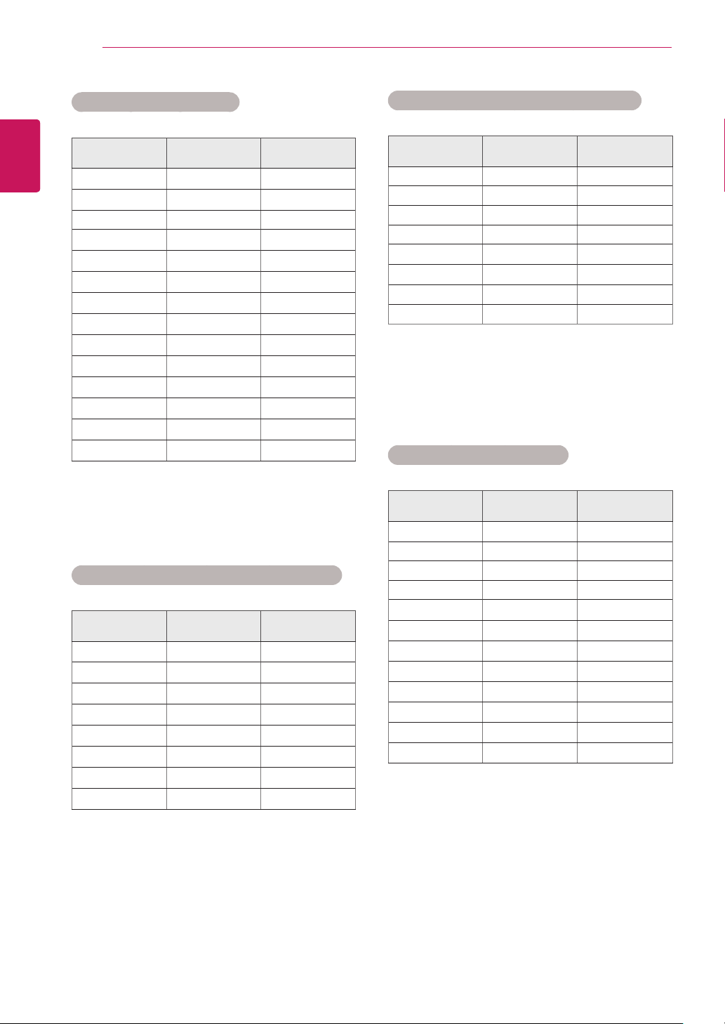
SPECIFICATIONS
64
ENGLISH
ENG
RGB (PC) supported mode
Resolution
640 x 480
640 x 480
720 x 400 31.468 70.8
800 x 600
800 x 600
832 x 624
1024 x 768
1024 x 768
1280 x 720
1366 x 768
1280 x 1024
1280 x 1024
1680 x 1050
1920 x 1080
Horizontal
Frequency(kHz)
31.469 59.94
37.5 75
37.879 60.317
46.875 75
49.725 74.55
48.363 60
60.123 75.029
44.772 59.855
47.7 60
63.981 60.02
79.98 75.02
65.290 59.954
67.5 60
Vertical
Frequency(Hz)
HDMI/DVI/Display Port(PC) supported mode
Resolution
640 x 480
800 x 600
1024 x 768
1280 x 720
1366 x 768
1280 x 1024
1680 x 1050
1920 x 1080
Horizontal
Frequency(kHz)
31.469 59.94
37.879 60.317
48.363 60
44.772 59.855
47.7 60
63.981 60.02
65.290 59.954
67.5 60
Vertical
Frequency(Hz)
HDMI/Display Port(DTV) supported mode
Resolution
480 / 60P 31.5 60
576 / 50P 31.25 50
720 / 50P 37.5 50
720 / 60P 45 60
1080 / 50i 28.1 50
1080 / 50P 56.25 50
1080 / 60i 33.75 60
1080 / 60P 67.5 60
Horizontal
Frequency(kHz)
Vertical
Frequency(Hz)
Component supported mode
Resolution
720 x 480 15.63 59.94
720 x 483 31.47 59.94
720 x 576 15.625 50.00
720 x 576 31.25 50.00
1280 x 720 45.00 60.00
1280 x 720 37.5 50
1280 x 720 44.96 59.94
1920 x 1080 31.25 50.00
1920 x 1080 56.25 50
1920 x 1080 33.75 60.00
1920 x 1080 33.72 59.94
1920 x 1080 67.5 60
Horizontal
Frequency(kHz)
Vertical
Frequency(Hz)
Page 65
SPECIFICATIONS
65
NOTE
When the cable is connected to the DVI,
y
HDMI or the Display Port, you can select the
PC/DTV mode optionally. It is recommended
you to set to the PC mode when connecting
to PC; the DTV mode when connecting to
DTV.
NOTE
Vertical frequency: To enable the user to
y
watch the product display, screen image
should be changed tens of times every
second like a fluorescent lamp. The vertical
frequency or refresh rate is the times of
image display per second. The unit is Hz.
Horizontal frequency: The horizontal interval
y
is the time to display one vertical line. When
1 is divided by the horizontal interval, the
number of horizontal lines displayed every
second can be tabulated as the horizontal
frequency. The unit is kHz.
ENGLISH
ENG
Page 66
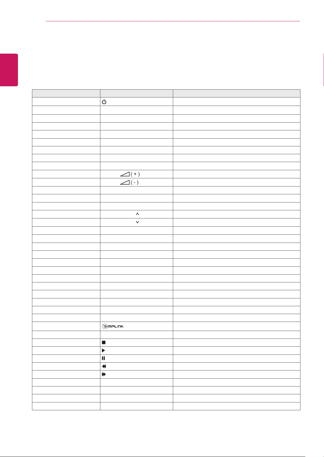
66
IR CODES
ENGLISH
IR CODES
ENG
All models do not support the HDMI/USB function.
y
Some key codes are not supported depending on the model.
y
Code (Hexa) Function Note
08
0B INPUT R/C BUTTON
C4 MONITOR ON R/C BUTTON
C5 MONITOR OFF R/C BUTTON
95 ENERGY SAVING R/C BUTTON
DC 3D R/C BUTTON
10 to 19 Number Key 0 to 9 R/C BUTTON
32 1/a/A R/C BUTTON
2F CLEAR R/C BUTTON
02
03
79 ARC R/C BUTTON
99 AUTO R/C BUTTON
09 MUTE R/C BUTTON
E0 BRIGHTNESS (Page UP) R/C BUTTON
E1 BRIGHTNESS (Page Down) R/C BUTTON
4D PSM R/C BUTTON
AA
5F W.BAL R/C BUTTON
43 MENU / SETTINGS(MENU) R/C BUTTON
40 Up ▲ R/C BUTTON
41 Down ▼ R/C BUTTON
07 Left ◄ R/C BUTTON
06 Right ► R/C BUTTON
3F S.MENU R/C BUTTON
44 OK R/C BUTTON
28 BACK R/C BUTTON
5B EXIT R/C BUTTON
7E R/C BUTTON
7B TILE (Tile Mode) R/C BUTTON
B1 R/C BUTTON
B0 R/C BUTTON
BA R/C BUTTON
8F R/C BUTTON
8E R/C BUTTON
72 Red Key (PICTURE ID ON) R/C BUTTON
71 Green Key (PICTURE ID OFF) R/C BUTTON
63 Yellow Key R/C BUTTON
61 Blue Key R/C BUTTON
Power
Volume
Volume
ⓘ
INFO
R/C BUTTON
R/C BUTTON
R/C BUTTON
R/C BUTTON
Page 67
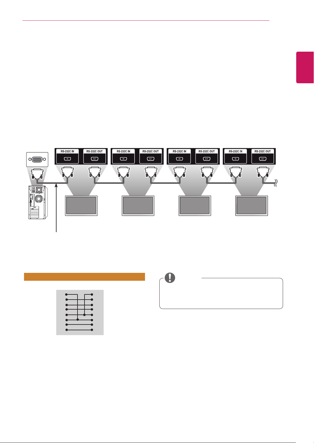
CONTROLLING THE MULTIPLE PRODUCT
67
CONTROLLING THE MULTIPLE PRODUCT
Use this method to connect several products to a single PC. You can control several products at one
y
time by connecting them to a single PC.
In the Option menu, Set ID must be between 1 and 255 (1 - 1,000 in certain models) without being
y
duplicated.
Connecting the cable
Connect the RS-232C cable as shown in the picture.
The RS-232C protocol is used for communication between the PC and product. You can turn the
y
product on/off, select an input source or adjust the OSD menu from your PC.
Monitor 1 Monitor 2 Monitor 3 Monitor 4
ENGLISH
ENG
RS-232C Cable
RS-232C Configurations
8-Wire Configurations (Cross-over RS-232C cable)
PC Set
DCD
1
RXD
2
TXD
3
GND
5
DTR
4
DSR
6
RTS
7
CTS
8
D-Sub 9 D-Sub 9
(Female) (Female)
DCD
1
TXD
3
RXD
2
GND
5
DSR
6
DTR
4
CTS
8
RTS
7
Communication Parameter
Baud Rate : 9600 BPS
y
Data Length : 8 bit
y
Parity Bit : None
y
Stop Bit : 1 bit
y
Flow Control : None
y
Communication Code : ASCII code
y
Use a crossed (reverse) cable
y
NOTE
When using 3-wire connections (non-
y
standard), an IR daisy chain cannot be used.
Page 68
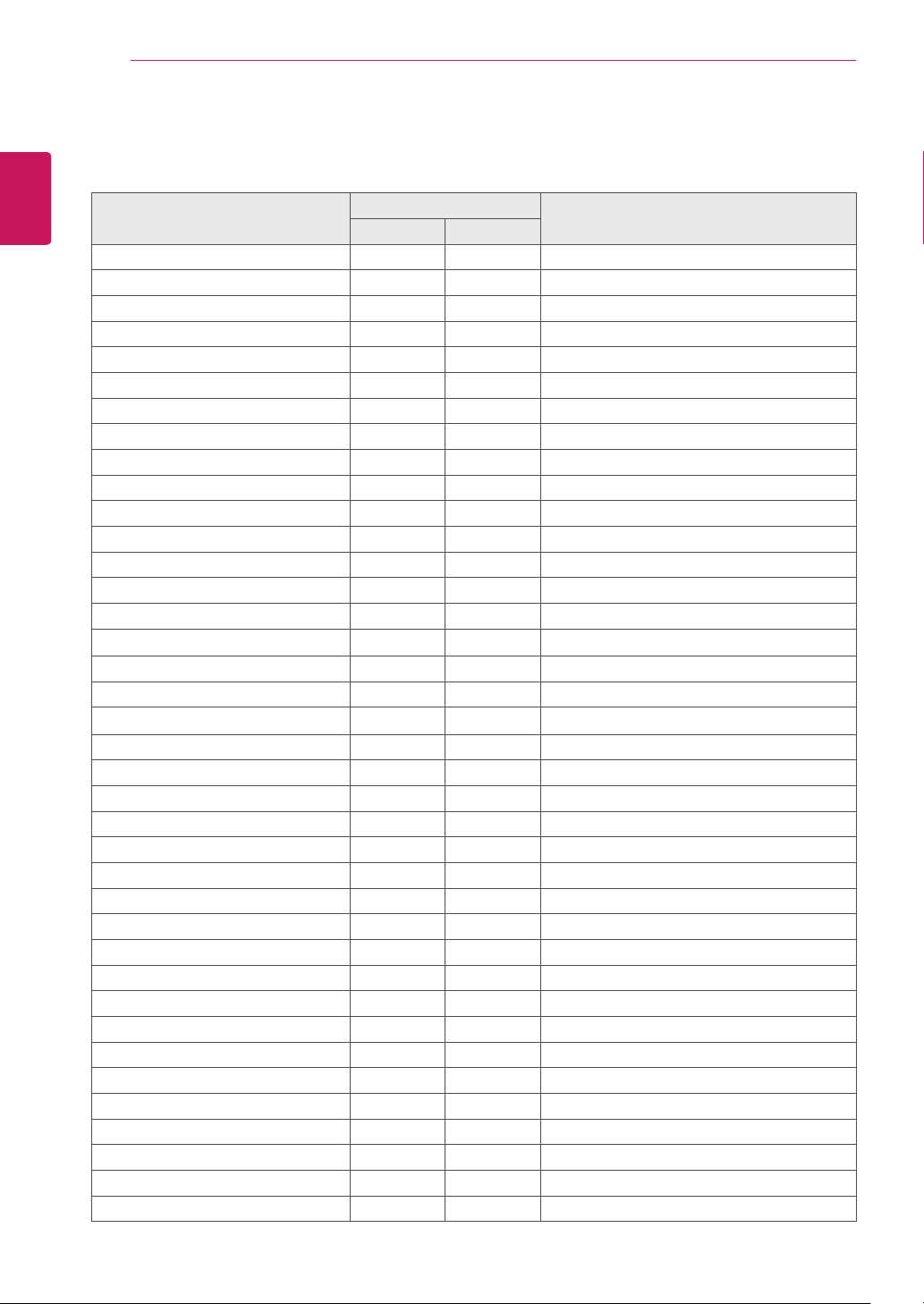
CONTROLLING THE MULTIPLE PRODUCT
68
ENGLISH
Command Reference List
ENG
COMMAND
1 2
01. Power
02. Input Select x b Refer to ‘Input Select'.
03. Aspect Ratio k c Refer to ‘Aspect Ratio'.
04. Energy Saving
05. Picture mode d x Refer to ‘Picture mode'.
06. Contrast k g 00 to 64
07. Brightness k h 00 to 64
08. Sharpness k k 00 to 64
09. Color k i 00 to 64
10. Tint k j 00 to 64
11. Color Temperature x u 00 to 64
12. H Position
13. V Position f r 00 to 64
14. H Size f s 00 to 64
15. Auto configuration
16. Balance
17. Sound mode d y Refer to ‘Sound mode'.
18. Treble k r 00 to 64
19. Bass k s 00 to 64
20. Speaker d v 00 to 01
21. Volume Mute k e 00 to 01
22. Volume Control
23. Time 1(Years/ Months/ Days) f a Refer to ‘Time 1'.
24. Time 2(Hours/ Minutes/Seconds) f x Refer to ‘Time 2'.
25. Off Timer(Repeat mode/ Time) f e Refer to ‘Off Timer'.
26. On Timer(Repeat Mode/ Time) f d Refer to ‘On Timer'.
27. On Timer Input f u Refer to ‘On Timer Input'.
28. Sleep Time f f 00 to 08
29. Power On Delay f h
30. Automatic Standby m n 00 to 01
31. Auto Off f g 00 to 01
32. Language f i Refer to ‘Language'.
33. Power Indicator(Standby Light) f o 00 to 01
34. Power Indicator(Power Light) f p 00 to 01
35. ISM mode j p Refer to ‘ISM Method'.
36. Fail Over Select
37. Fail Over Input Select m j Refer to ‘Fail Over Input Select.'
38. Reset f K 00 to 02
k a
j q
f q
j u
k t
k f
m i
00 to 01
Refer to ‘Energy Saving'.
00 to 64
01
00 to 64
00 to 64
00 to 64 (00 - FA in certain models)
00 to 02
DATA
(Hexadecimal)
Page 69
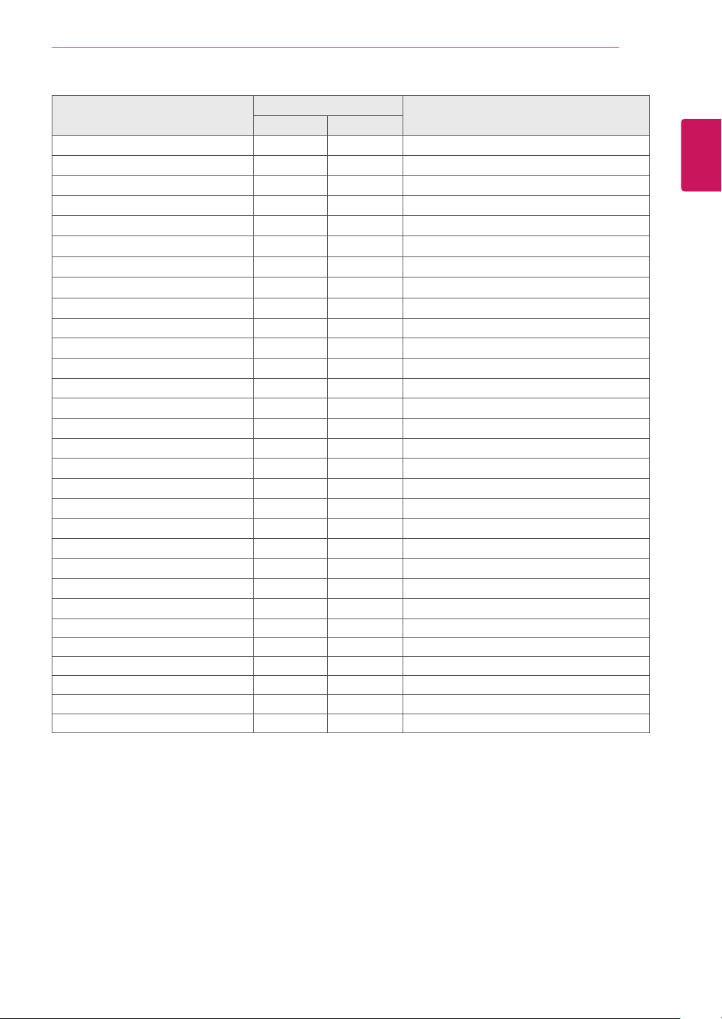
CONTROLLING THE MULTIPLE PRODUCT
69
COMMAND
1 2
39. Tile Mode d d 00 to 01
40. Tile Mode Check d z FF
41. Tile ID d i Refer to ‘Tile ID'.
42. Tile H Position d e 00 to 32
43. Tile V Position d f 00 to 32
44. Tile H Size d g 00 to 32
45. Tile V Size d h 00 to 32
46. Natural Mode (In Tile mode) d j 00 to 01
47. DPM Select f j 00 to 01
48. FAN Control
49. FAN Fault Check d w FF
50. Temperature Value d n FF
51. Remote Lock/ key Lock
52. Key m c Refer to ‘Key'.
53. OSD Select k l 00 to 01
54. Elapsed time return d l FF
55. Serial No. Check f y FF
56. S/W Version f z FF
57. White Balance Red Gain j m 00 to FE
58. White Balance Green Gain
59. White Balance Blue Gain
60. Backlight
61. PC Power Control
62. PC Power
63. Easy Brightness Control Mode
64. Easy Brightness Control Schedule
65. Reading luminance values
66. Status check
67. BLU Maintenance
68. Screen mute
d o
k m
j
j
m
d
d
s m
s s
m u
s v
m t
k d
n 00 to FE
o 00 to FE
g 00 to 64
t 00 to 01
s 00 to 01
00 to 03
00 to 01
00 to 01
Refer to ‘Easy Brightness Control Schedule'.
Refer to ‘Reading luminance values’.
Refer to ‘Status check.’
00 to 01
00 to 01
DATA
(Hexadecimal)
ENGLISH
ENG
Note : During USB operations such as Dvix or EMF, all commands except Power (k a) and Key (m c)
y
are not executed and treated as NG.
Some commands are not supported depending on the model.
y
The ‘f f’ command which shows the status of a certain command does not display the OSD as the
y
result in order to be compatible with SuperSign program.
Page 70

CONTROLLING THE MULTIPLE PRODUCT
70
ENGLISH
Transmission / Receiving Protocol
ENG
[Command1][Command2][ ][Set ID][ ][Data][Cr]
[Command2][ ][Set ID][ ][OK/NG][Data][x]
Transmission
* [Command1] Identifies the factory setting and the user setting modes.
* [Command2] Controls monitors.
* [Set ID] Used for selecting a set you want to control. A Set ID can be assigned to each set from
1 to 255 (from 01H to FFH), or from 1 to 1,000 (from 001H to 3e8H) in certain models
under OPTION in the OSD menu. Selecting '00H' or '000H' for set ID allows the simultaneous control of all connected monitors. (Depending on the model, this feature may not
be supported.)
* [Data] Transmits command data.
Data count may increase depending on the command.
* [Cr] Carriage Return. Corresponds to '0x0D' in ASCII code.
* [ ] White Space. Corresponds to '0x20' in ASCII code.
Acknowledgement
* The Product transmits an ACK (acknowledgement) based on this format when receiving normal data. At
this time, if the data is FF, it indicates the present status data. If the data is in data write mode, it returns
the data of the PC computer.
* If a command is sent with Set ID ‘00’ (=0x00) or ‘000’(=0x000), the data is reflected to all monitors and
they do not send an acknowledgement (ACK).
* If the data value 'FF' is sent in control mode via RS-232C, the current setting value of a function can be
checked (only for some functions).
* Some commands may not be supported on some models.
Page 71

CONTROLLING THE MULTIPLE PRODUCT
71
01. Power (Command: k a)
To control the Power On/Off the display.
Transmission
[k][a][ ][Set ID][ ][Data][Cr]
Data 00 : Off
01 : On
Acknowledgement
[a][ ][Set ID][ ][OK/NG][Data][x]
* Only when the monitor set is fully powered on, the
Acknowledgement signal is returned properly.
* There may be a certain time of delay between the
Transmission and Acknowledgement signals.
02. Input Select (Command: x b)
To select the Input Source for display.
Transmission
[x][b][ ][Set ID][ ][Data][Cr]
Data 20: Input (AV)
40: Component
60: RGB
70: DVI-D(PC)
80: DVI-D(DTV)
90: HDMI(HDMI1)(DTV)
A0: HDMI(HDMI1)(PC)
C0: Display Port(DTV)
D0: Display Port(PC)
91: HDMI2/SDI(DTV)
A1: HDMI2/SDI(PC)
B0: SuperSign
Acknowledgement
[b][ ][Set ID][ ][OK/NG][Data][x]
* Some input signals may not be supported
depending on the model.
04. Energy Saving (Command: j q)
To set the Energy Saving function.
Transmission
[j][q][ ][Set ID][ ][Data][Cr]
Data 00: Off
01: Minimum
02: Medium
03. Maximum
04: Auto
05. Screen Off
Acknowledgement
[q][ ][Set ID][ ][OK/NG][Data][x]
** It may not be supported depending on the model.
05. Picture Mode (Command: d x)
To select the Picture Mode.
Transmission
[d][x][ ][Set ID][ ][Data][Cr]
Data 00: Vivid
01: Standard
02. Cinema
03. Sport
04: Game
Acknowledgement
[x][ ][Set ID][ ][OK/NG][Data][x]
ENGLISH
ENG
03. Aspect Ratio (Command: k c)
To adjust the screen format.
Transmission
[k][c][ ][Set ID][ ][Data][Cr]
Data 01: 4:3
02: 16:9
04: Zoom
(AV, Component, HDMI/ DVI-D/ Display Port DTV)
09: Just scan (720p or more)
(Component, HDMI/ DVI-D/ Display Port DTV)
* RGB, DVI-D, HDMI/Display Port PC mode (1:1)
10 to 1F: Cinema Zoom 1 to 16
(AV, Component, HDMI/ DVI-D/ Display Port DTV)
* Available data types differ depending on the input
signal. For more information, see the aspect ratio
section of the owner's manual.
* The aspect ratio may differ depending on the
model's input configuration.
Acknowledgement
[c][ ][Set ID][ ][OK/NG][Data][x]
06. Contrast (Command: k g)
To adjust the screen contrast.
Transmission
[k][g][ ][Set ID][ ][Data][Cr]
Data 00 to 64: Contrast 0 to 100
Acknowledgement
[g][ ][Set ID][ ][OK/NG][Data][x]
Page 72

CONTROLLING THE MULTIPLE PRODUCT
72
07. Brightness (Command: k h)
ENGLISH
ENG
08. Sharpness (Command: k k)
To adjust the screen brightness.
Transmission
[k][h][ ][Set ID][ ][Data][Cr]
Data 00 to 64: Brightness 0 to 100
Acknowledgement
[h][ ][Set ID][ ][OK/NG][Data][x]
To adjust the screen sharpness.
* This function is available only in AV/Component
input and DTV mode.
Transmission
[k][k][ ][Set ID][ ][Data][Cr]
Data 00 to 64: Sharpness 0 to 100
Acknowledgement
[k][ ][Set ID][ ][OK/NG][Data][x]
10. Tint (Command: k j)
To adjust the screen tint.
* This function is available only in AV/Component
input and DTV mode.
Transmission
[k][j][ ][Set ID][ ][Data][Cr]
Data 00 to 64: Tint R50 to G50
Acknowledgement
[j][ ][Set ID][ ][OK/NG][Data][x]
11. Color Temperature (Command: x u)
To adjust the screen Color Temperature.
Transmission
[x][u][ ][Set ID][ ][Data][Cr]
Data 00 to 64: Warm 50 to Cool 50
Acknowledgement
[u][ ][Set ID][ ][OK/NG][Data][x]
09. Color (Command: k i)
To adjust the screen color.
* This function is available only in AV/Component
input and DTV mode.
Transmission
[k][i][ ][Set ID][ ][Data][Cr]
Data 00 to 64: Color 0 to 100
Acknowledgement
[i][ ][Set ID][ ][OK/NG][Data][x]
12. H Position (Command: f q)
To adjust the screen Horizontal Position.
* This function is available only when the Tile Mode is
set to Off.
* The operational range varies depending on the
RGB input resolution.
(Only available for RGB-PC input.)
Transmission
[f][q][ ][Set ID][ ][Data][Cr]
Data 00 to 64: min. -50 (Left) to max. 50 (Right)
Acknowledgement
[q][ ][Set ID][ ][OK/NG][Data][x]
Page 73

CONTROLLING THE MULTIPLE PRODUCT
73
13. V Position (Command: f r)
To adjust the screen Vertical Position.
* This function is available only when the Tile Mode is
set to Off.
* The operational range varies depending on the
RGB input resolution.
(Only available for RGB-PC input.)
Transmission
[f][r][ ][Set ID][ ][Data][Cr]
Data 00 to 64: min. -50 (Bottom) to max. 50 (Top)
Acknowledgement
[r][ ][Set ID][ ][OK/NG][Data][x]
14. H Size (Command: f s)
To adjust the screen Horizontal Size.
* This function is available only when the Tile Mode is
set to Off.
* The operational range varies depending on the
RGB input resolution.
(Only available for RGB-PC input.)
Transmission
[f][s][ ][Set ID][ ][Data][Cr]
Data 00 - 64: Min. -50 (Reduce) - Max. 50 (Expand)
Acknowledgement
[s][ ][Set ID][ ][OK/NG][Data][x]
16. Balance (Command: k t)
To adjust the sound balance.
Transmission
[k][t][ ][Set ID][ ][Data][Cr]
Data 00 to 64: Left 50 to Right 50
Acknowledgement
[t][ ][Set ID][ ][OK/NG][Data][x]
** It may not be supported depending on the model.
17. Sound Mode (Command: d y)
To select the Sound Mode.
Transmission
[d][y][ ][Set ID][ ][Data][Cr]
Data 01: Standard
02: Music
03: Cinema
04: Sport
05. Game
Acknowledgement
[y][ ][Set ID][ ][OK/NG][Data][x]
** It may not be supported depending on the model.
ENGLISH
ENG
15. Auto Configuration (Command: j u)
To adjust the picture position and minimize image
shaking automatically.
(Only available for RGB-PC input.)
Transmission
[j][u][ ][Set ID][ ][Data][Cr]
Data 01 : Set
Acknowledgement
[u][ ][Set ID][ ][OK/NG][Data][x]
18. Treble (Command: k r)
To adjust the Treble values.
Transmission
[k][r][ ][Set ID][ ][Data][Cr]
Data 00 to 64: Treble 0 to 100
Acknowledgement
[r][ ][Set ID][ ][OK/NG][Data][x]
** It may not be supported depending on the model.
Page 74

CONTROLLING THE MULTIPLE PRODUCT
74
19. Bass (Command: k s)
ENGLISH
ENG
20. Speaker (Command: d v)
To adjust the Bass values.
Transmission
[k][s][ ][Set ID][ ][Data][Cr]
Data 00 to 64: Bass 0 to 100
Acknowledgement
[s][ ][Set ID][ ][OK/NG][Data][x]
** It may not be supported depending on the model.
To select the speaker on/off.
Transmission
[d][v][ ][Set ID][ ][Data][Cr]
Data 00: Off
01: On
Acknowledgement
[v][ ][Set ID][ ][OK/NG][Data][x]
** It may not be supported depending on the model.
22. Volume Control (Command: k f)
To set the playback volume.
Transmission
[k][f][ ][Set ID][ ][Data][Cr]
Data 00 to 64: Volume 0 to 100
Acknowledgement
[f][ ][Set ID][ ][OK/NG][Data][x]
** It may not be supported depending on the model.
23. Time 1(Year/ Month/ Day) (Command: f a)
To set the Time 1(Year/ Month/ Day) values.
Transmission
[f][a][ ][Set ID][ ][Data1][ ][Data2][ ][Data3][Cr]
Data 1 00 to 14: 2010 to 2030
Data 2 01 to 0C: January to December
Data 3 01 to 1F: 1 to 31
* Enter “fa [Set ID] ff” for checking Time 1(Year/
Month/ Day) values.
Acknowledgement
[a][ ][Set ID][ ][OK/NG][Data1][Data2][Data3][x]
21. Volume Mute (Command: k e)
To control the Volume Mute on/off.
Transmission
[k][e][ ][Set ID][ ][Data][Cr]
Data 00 : Mute (Volume Off)
01 : Current volume (Volume On)
Acknowledgement
[e][ ][Set ID][ ][OK/NG][Data][x]
24. Time 2(Hour/ Minute/ Second) (Command: f x)
To set the Time 2(Hour/ Minute/ Second) values.
Transmission
[f][x][ ][Set ID][ ][Data1][ ][Data2][ ][Data3][Cr]
Data1 00 to 17: 00 to 23 hours
Data2 00 to 3B: 00 to 59 minutes
Data3 00 to 3B: 00 to 59 seconds
* Enter “fx [Set ID] ff” for checking Time 2(Hour/
Minute/ Second) values.
** This command won’t work if Time 1(Year/ Month/
Day) has not been set in advance.
Acknowledgement
[x][ ][Set ID][ ][OK/NG][Data1][Data2][Data3][x]
Page 75
CONTROLLING THE MULTIPLE PRODUCT
75
25. Off Timer(Repeat Mode/ Time) (Command: f e)
To set the Off Timer(Repeat Mode/ Time) function.
Transmission
[f][e][ ][Set ID][ ][Data1][ ][Data2][ ][Data3][Cr]
Data1
1. F1 to F7 (Read data)
F1: Read the 1st Off Time data
F2: Read the 2nd Off Time data
F3: Read the 3rd Off Time data
F4: Read the 4th Off Time data
F5: Read the 5th Off Time data
F6: Read the 6th Off Time data
F7: Read the 7th Off Time data
2. E1-E7 (Delete one index), E0 (Delete all indexes)
E0: Delete all Off Time data
E1: Delete the 1st Off Time data
E2: Delete the 2nd Off Time data
E3: Delete the 3rd Off Time data
E4: Delete the 4th Off Time data
E5: Delete the 5th Off Time data
E6: Delete the 6th Off Time data
E7: Delete the 7th Off Time data
3. 01 to 0C (Set the day of week for Off Time)
00: Off
01: Once
02. Daily
03: Monday to Friday
04: Monday to Saturday
05: Saturday to Sunday
06. Sunday
07. Monday
08. Tuesday
09. Wednesday
0A. Thursday
0B. Friday
0C. Saturday
Data2 00 to 17: 00 to 23 Hours
Data3 00 to 3B: 00 to 59 Minutes
* To read or delete the Off Time list, set FFH for
[Data2] and [Data3].
(Example 1: fe 01 f1 ff ff - Read the 1st Off Time
data.)
(Example 2: fe 01 e1 ff ff - Delete the 1st Off Time
data.)
(Example 3: fe 01 04 02 03 - Set the Off Time to
"Monday to Saturday, 02:03".)
* This function is supported only when 1 (Year/Month/
Day) and 2 (Hour/Minute/Second) are set.
Acknowledgement
[e][ ][Set ID][ ][OK/NG][Data1][Data2][Data3][x]
26. On Timer(Repeat Mode/ Time) (Command: f d)
To set the On Timer(Repeat mode/ Time) function.
Transmission
[f][d][ ][Set ID][ ][Data1][ ][Data2][ ][Data3][Cr]
Data1
1. F1 to F7 (Read data)
F1: Read the 1st On Time data
F2: Read the 2nd On Time data
F3: Read the 3rd On Time data
F4: Read the 4th On Time data
F5: Read the 5th On Time data
F6: Read the 6th On Time data
F7: Read the 7th On Time data
2. E1-E7 (Delete one index), E0 (Delete all indexes)
E0: Delete all On Time data
E1: Delete the 1st On Time data
E2: Delete the 2nd On Time data
E3: Delete the 3rd On Time data
E4: Delete the 4th On Time data
E5: Delete the 5th On Time data
E6: Delete the 6th On Time data
E7: Delete the 7th On Time data
3. 01 to 0C (Set the day of week for On Time)
00: Off
01: Once
02. Daily
03: Monday to Friday
04: Monday to Saturday
05: Saturday to Sunday
06. Sunday
07. Monday
08. Tuesday
09. Wednesday
0A. Thursday
0B. Friday
0C. Saturday
Data2 00 to 17: 00 to 23 Hours
Data3 00 to 3B: 00 to 59 Minutes
* To read or delete the Off Time list, set FFH for
[Data2] and [Data3].
(Example 1: fd 01 f1 ff ff - Read the 1st On Time
data.)
(Example 2: fd 01 e1 ff ff - Delete the 1st On Time
data.)
(Example 3: fd 01 04 02 03 - Set the On Time to
"Monday to Saturday, 02:03".)
* This function is supported only when 1 (Year/Month/
Day) and 2 (Hour/Minute/Second) are set.
Acknowledgement
[d][ ][Set ID][ ][OK/NG][Data1][Data2][Data3][x]
ENGLISH
ENG
Page 76
CONTROLLING THE MULTIPLE PRODUCT
76
27. On Timer Input (Command: f u)
ENGLISH
ENG
To select an external input for the current On Time
setting and add a new schedule or change the
existing schedule.
Transmission
[f][u][ ][Set ID][ ][Data1][Cr]
[f][u][ ][Set ID][ ][Data1][Data2][Cr]
Data (Add schedule)
20: Input (AV)
40: Component
60. RGB
70: DVI-D
90: HDMI (HDMI1)
C0: Display Port
91: HDMI2/SDI
B0:SuperSign
Data1 (Change schedule)
1. F1 to F7 (Read data)
F1: Select the 1st schedule input
F2: Select the 2nd schedule input
F3: Select the 3rd schedule input
F4: Select the 4th schedule input
F5: Select the 5th schedule input
F6: Select the 6th schedule input
F7: Select the 7th schedule input
Data2
20: Input (AV)
40: Component
60: RGB
70: DVI-D
90: HDMI (HDMI1)
C0: Display Port
91: HDMI2/SDI
B0:SuperSign
* To read the schedule input, enter FFH for [Data2].
If no schedule is available for [Data1] when
attempting to read or change the schedule data, the
text NG will be displayed and the operation fails.
(Example 1: fu 01 60 - Move each schedule input
down one row and save the 1st schedule input in
RGB mode.)
(Example 2: fu 01 f1 ff - Read the 1st schedule input.)
(Example 3: fu 01 f3 20 - Change the 3rd data
schedule input to the current On Time and AV input.
If there is no third schedule, the text NG will be
displayed and the operation fails.)
* This function is supported only when 1 (Year/Month/
Day), 2 (Hour/Minute/Second), On Time (Repeat
Mode/Time) are set.
** It may not be supported depending on the model.
Acknowledgement
[u][ ][Set ID][ ][OK/NG][Data][x]
[u][ ][Set ID][ ][OK/NG][Data1][Data2][x]
28. Sleep Time (Command: f f)
To set the Sleep Time.
Transmission
[f][f][ ][Set ID][ ][Data][Cr]
Data 00: Off (Sleep Timer off)
01: 10 min.
02: 20 min.
03: 30 min.
04: 60 min.
05: 90 min.
06: 120 min.
07: 180 min.
08: 240 min.
Acknowledgement
[f][ ][Set ID][ ][OK/NG][Data][x]
29. Power On Delay (Command: f h)
To set the schedule delay when the power is turned
on. (Unit: Second)
Transmission
[f][h][ ][Set ID][ ][Data][Cr]
Data 00 to 64: min. 0 to max. 100 (sec.)
(Data 00 - FA in certain models: min 0 - max 250
(sec.))
Acknowledgement
[h][ ][Set ID][ ][OK/NG][Data][x]
30. Automatic Standby (Command: m n)
To set the Automatic Standby function.
Transmission
[m][n][ ][Set ID][ ][Data][Cr]
Data 00: Off (No off after 4 hours)
01: 4 Hours (Off after 4 hours)
Acknowledgement
[n][ ][Set ID][ ][OK/NG][Data][x]
Page 77

CONTROLLING THE MULTIPLE PRODUCT
77
31. Auto Off (Command: f g)
To set the Auto Off function.
Transmission
[f][g][ ][Set ID][ ][Data][Cr]
Data 00: Off (No off after 15 minutes)
01: 15 min.(Off after 15 minutes)
Acknowledgement
[g][ ][Set ID][ ][OK/NG][Data][x]
32. Language (Command: f i)
To set the language for OSD.
Transmission
[f][i][ ][Set ID][ ][Data][Cr]
Data 00: Czech
01: Danish
02: German
03: English
04: Spanish (EU)
05: Greek
06: French
07: Italian
08: Dutch
09: Norwegian
0A: Portuguese
0B: Portuguese (BR)
0C: Russian
0D: Finnish
0E: Swedish
0F: Korean
10: Chinese (Mandarin)
11: Japanese
12: Yue Chinese (Cantonese)
Acknowledgement
[i][ ][Set ID][ ][OK/NG][Data][x]
34. Power Indicator (Power Light) (Command: f p)
To set the Power Indicator (Power Light) function.
Transmission
[f][p][ ][Set ID][ ][Data][Cr]
Data 00: Off
01: On
** It may not be supported depending on the model.
Acknowledgement
[p][ ][Set ID][ ][OK/NG][Data][x]
35. ISM mode (Command: j p)
To select ISM method for avoiding having a fixed
image remain on screen.
Transmission
[j][p][ ][Set ID][ ][Data][Cr]
Data 01: Inversion
02: Orbiter
04: White Wash
08. Normal
Acknowledgement
[p][ ][Set ID][ ][OK/NG][Data][x]
ENGLISH
ENG
33. Power Indicator (Standby Light) (Command: f o)
To set the Power Indicator (Standby Light) function.
Transmission
[f][o][ ][Set ID][ ][Data][Cr]
Data 00: Off
01: On
** It may not be supported depending on the model.
Acknowledgement
[o][ ][Set ID][ ][OK/NG][Data][x]
36. Fail Over Select (Command: m i)
To set the Fail Over function.
Transmission
[m][i][ ][Set ID][ ][Data][Cr]
Data 00: Off
01: Auto
02: Manual
Acknowledgement
[i][ ][Set ID][ ][OK/NG][Data][x]
Page 78

CONTROLLING THE MULTIPLE PRODUCT
78
37. Fail Over Input Select (Command: m j)
ENGLISH
ENG
38. Reset (Command: f k)
39. Tile Mode (Command: d d)
To select the input source for auto switch.
* This command is only available when the fail over
(auto) mode is set to Manual.
Transmission
[m][j][ ][Set ID][ ][Data1][ ][Data2][ ][Data3][Cr]
[ ][Data4][ ][Data5][Cr]
Data 1 to 5 (Priority 1 to 5)
60: RGB
70: DVI-D
90: HDMI(HDMI1)
C0: Display Port
91: HDMI2/SDI
* The number of data items differs depending on the
model.
Acknowledgement
[j][ ][SetID][ ][OK/NG][Data1][Data2][Data3][Data4]
[ ][Data5][x]
To execute the Picture, Screen, Audio and Factory
reset function.
(Screen Reset can only be performed in RGB input
mode.)
Transmission
[f][k][ ][Set ID][ ][Data][Cr]
Data 00: Picture Reset
01: Screen Reset
02: Factory Reset
03: Audio Reset
Acknowledgement
[k][ ][Set ID][ ][OK/NG][Data][x]
To set a Tile Mode and Tile Column/ Row values.
Transmission
[d][d][ ][Set ID][ ][Data][Cr]
Data 00 to FF: 1st byte - Tile Row
2nd byte - Tile Column
*00, 01, 10, 11 means Tile Mode Off
** It may not be supported depending on the model.
Acknowledgement
[d][ ][Set ID][ ][OK/NG][Data][x]
40. Tile Mode Check (Command: d z)
To check Tile Mode status.
Transmission
[d][z][ ][Set ID][ ][Data][Cr]
Data FF: Check Tile Mode status.
** It may not be supported depending on the model.
Acknowledgement
[z][ ][Set ID][ ][OK/NG][Data1][Data2][Data3][x]
Data1 00: Tile Mode Off
01: Tile Mode On
Data2 00 to 0F: Tile Row
Data3 00 to 0F: Tile Column
41. Tile ID (Command: d i)
To set Tile ID.
Transmission
[d][i][ ][Set ID][ ][Data][Cr]
Data 01 to E1: Tile ID 01 to 225**
FF: Check Tile ID
** Data could not be set over (Tile Column) x (Tile
Row).
** It may not be supported depending on the model.
Acknowledgement
[i][ ][Set ID][ ][OK/NG][Data][x]
*NG will be return if data is over (Tile Column) x (Tile
Row), except 0xFF.
42. Tile H Position (Command: d e)
To adjust the Tile Horizontal position.
* This function is available only when the Natural
option of the Tile Mode is set to Off while the Tile
Mode set to On.
Transmission
[d][e][ ][Set ID][ ][Data][Cr]
Data 00 to 32: -50 (Left) to 0 (Right)
*Left/Right values depend on Tile H size.
** It may not be supported depending on the model.
Acknowledgement
[e][ ][Set ID][ ][OK/NG][Data][x]
Page 79

CONTROLLING THE MULTIPLE PRODUCT
79
43. Tile V Position (Command: d f)
To adjust the Tile Vertical position.
* This function is available only when the Natural
option of the Tile Mode is set to Off while the Tile
Mode set to On.
Transmission
[d][f][ ][Set ID][ ][Data][Cr]
Data 0 to 32: 0 (Bottom) to 50 (Top)
* Bottom/Top values depend on Tile Vertical size.
** It may not be supported depending on the model.
Acknowledgement
[f][ ][Set ID][ ][OK/NG][Data][x]
44. Tile H Size (Command: d g)
To adjust the Tile Horizontal Size.
*Set Tile H Position to 0x32 before setting Tile H
Size.
* This function is available only when the Natural
option of the Tile Mode is set to Off while the Tile
Mode set to On.
Transmission
[d][g][ ][Set ID][ ][Data][Cr]
Data 00 to 32: 0 to 50
** It may not be supported depending on the model.
Acknowledgement
[g][ ][Set ID][ ][OK/NG][Data][x]
46. Natural Mode (In Tile Mode) (Command : d j)
To display the image naturally, the part of the image
that would normally be displayed in the gap between
the monitors is omitted.
Transmission
[d][j][ ][Set ID][ ][Data][Cr]
Data 00: Off
01: On
Acknowledgement
[j][ ][Set ID][ ][OK/NG][Data][x]
47. DPM Select (Command: f j)
To set the DPM (Display Power Management)
function.
Transmission
[f][j][ ][Set ID][ ][Data][Cr]
Data 00: Off
01: On
* Data settings may vary depending on your model
as below.
Data 00: Off
01: 5 sec.
02: 10 sec.
03: 15 sec.
04: 1 min.
05: 3 min.
06: 5 min.
07: 10 min.
Acknowledgement
[j][ ][Set ID][ ][OK/NG][Data][x]
ENGLISH
ENG
45. Tile V Size (Command: d h)
To adjust the Tile Vertical size.
*Set Tile V Position to 0x00 before setting Tile V
Size.
* This function is available only when the Natural
option of the Tile Mode is set to Off while the Tile
Mode set to On.
Transmission
[d][h][ ][Set ID][ ][Data][Cr]
Data 00 to 32: 0 to 50
** It may not be supported depending on the model.
Acknowledgement
[h][ ][Set ID][ ][OK/NG][Data][x]
48. FAN Control (Command : d o)
To set the Fan mode.
Transmission
[d][o][ ][Set ID][ ][Data][Cr]
Data 00: Auto
01: On
02: Manual
03: Off
** It may not be supported depending on the model.
Acknowledgement
[o][ ][Set ID][ ][OK/NG][Data][x]
Page 80
CONTROLLING THE MULTIPLE PRODUCT
80
49. FAN Fault Check (Command: d w)
ENGLISH
ENG
50. Temperature Value (Command: d n)
To check the fan errors.
Transmission
[d][w][ ][Set ID][ ][Data][Cr]
Data FF: Read the status
Acknowledgement
[w][ ][Set ID][ ][OK/NG][Data][x]
Data 00: Fan fault
01: Fan OK
02: Model without a Fan
To check the inside temperature value.
Transmission
[d][n][ ][Set ID][ ][Data][Cr]
Data FF: Check the status
Acknowledgement
[n][ ][Set ID][ ][OK/NG][Data][x]
[n][ ][Set ID][ ][OK/NG][Data1][Data2][Data3][x]
* Temperature is displayed in hexadecimal.
52. Key (Command: m c)
To send a key code of the IR remote control.
Transmission
[m][c][ ][Set ID][ ][Data][Cr]
Data IR_KEY_CODE
Acknowledgement
[c][ ][Set ID][ ][OK/NG][Data][x]
For a key code, see the IR Code.
* Some key codes are not supported depending on
the model.
53. OSD Select (Command: k l)
To select OSD(On Screen Display) on/off.
Transmission
[k][l][ ][Set ID][ ][Data][Cr]
Data 00: Off
01: On
Acknowledgement
[l][ ][Set ID][ ][OK/NG][Data][x]
51. Remote Controller Lock/ Key Lock
(Command: k m)
When the remote control and front keys are locked in
standby mode, the power cannot be turned on using
the remote control or front power button.
Transmission
[k][m][ ][Set ID][ ][Data][Cr]
Data 00: Off (Lock Off)
01: On (Lock On)
* Display will not be turned on by power on key of
remote controller and front panel control keys, if key
is locked on in standby mode.
Acknowledgement
[m][ ][Set ID][ ][OK/NG][Data][x]
** It may not be supported depending on the model.
54. Elapsed time return (Command: d l)
To check the panel used time.
Transmission
[d][l][ ][Set ID][ ][Data][Cr]
Data FF: Read the status
Acknowledgement
[l][ ][Set ID][ ][OK/NG][Data][x]
* Returned data means used hours in hexadecimal.
Page 81
CONTROLLING THE MULTIPLE PRODUCT
81
55. Serial No.Check (Command: f y)
To check the Serial Numbers.
Transmission
[f][y][ ][Set ID][ ][Data][Cr]
Data FF: Check the product Serial Number
Acknowledgement
[y][ ][Set ID][ ][OK/NG][Data][x]
* Data is ASCII code.
56. S/W Version (Command: f z)
To check the Software Version.
Transmission
[f][z][ ][Set ID][ ][Data][Cr]
Data FF: Check the Software version
Acknowledgement
[z][ ][Set ID][ ][OK/NG][Data][x]
58. White Balance Green Gain (Command: j n)
To set the White Balance Green Gain.
Transmission
[j][n][ ][Set ID][ ][Data][Cr]
Data 00 to FE: Green Gain 0 to 254
Acknowledgement
[n][ ][Set ID][ ][OK/NG][Data][x]
59. White Balance Blue Gain (Command: j o)
To set the White Balance Blue Gain.
Transmission
[j][o][ ][Set ID][ ][Data][Cr]
Data 00 to FE: Blue Gain 0 to 254
Acknowledgement
[o][ ][Set ID][ ][OK/NG][Data][x]
ENGLISH
ENG
57. White Balance Red Gain (Command: j m)
To set the White Balance Red Gain.
Transmission
[j][m][ ][Set ID][ ][Data][Cr]
Data 00 to FE: Red Gain 0 to 254
Acknowledgement
[m][ ][Set ID][ ][OK/NG][Data][x]
60. Backlight (Command: m g)
To adjust the screen backlight.
Transmission
[m][g][ ][Set ID][ ][Data][Cr]
Data 00 to 64: Backlight 0 to 100
Acknowledgement
[g][][set ID][][OK/NG][Data][x]
** It may not be supported depending on the model.
Page 82

CONTROLLING THE MULTIPLE PRODUCT
82
61. PC Power Control (Command: d t)
ENGLISH
ENG
62. PC Power (Command: d s)
To control the PC power if the PC and the monitor
are synchronized.
Transmission
[d][t][ ][Set ID][ ][Data][Cr]
Data
00: Synchronized (When the monitor is off, the PC is
also turned off.)
01: Not synchronized (The monitor is off but the PC
is on.)
02: Keeps your PC powered on (When you turn on
the monitor while the PC is turned off, the PC is
turned on.).
** It may not be supported depending on the model.
Acknowledgement
[t][ ][Set ID][ ][OK][Data][x]
Control the PC power.
Transmission
[d][s][ ][Set ID][ ][Data][Cr]
Data 00: PC is turned off.
01: PC is turned on.
** It may not be supported depending on the model.
Acknowledgement
[s][ ][Set ID][ ][OK][Data][x]
64. Easy Brightness Control Schedule (Command: s
s)
Sets the Easy Brightness Control Schedule.
Transmission
[s][s][ ][Set ID][ ][Data1][ ][Data2][ ][Data3][Cr]
Data1
1. F1 - F6 (Data Reading Functions)
F1: Reads the data of the 1st Easy Brightness
Control
F2: Reads the data of the 2nd Easy Brightness
Control
F3: Reads the data of the 3rd Easy Brightness
Control
F4: Reads the data of the 4th Easy Brightness
Control
F5: Reads the data of the 5th Easy Brightness
Control
F6: Reads the data of the 6th Easy Brightness
Control
2. E1-E6 (Deletes One Index), E0 (Delete All
Indexes)
E0: Deletes all Easy Brightness Controls
E1: Deletes the 1st Easy Brightness Control
E2: Deletes the 2nd Easy Brightness Control
E3: Deletes the 3rd Easy Brightness Control
E4: Deletes the 4th Easy Brightness Control
E5: Deletes the 5th Easy Brightness Control
E6: Deletes the 6th Easy Brightness Control
3. 00-17: 00 - 23:00
Data2 00-3B: 00 - 59 minutes
Data3 00-64: backlight 0 - 100
* To read or delete the configured Easy Brightness
Control list, set [Data2][Data3] to FF.
(ex1: ss 01 f1 ff ff - Reads the 1st index data from the
Easy Brightness Control.
ex2: ss 01 e1 ff ff - Deletes the 1st index data from
the Easy Brightness Control.
ex3: ss 01 07 1E 46 - Adds a schedule to the
backlight 70 at 07:30.)
Acknowledgement
[s][ ][Set ID][ ][OK/NG][Data1][Data2][Data3][x]
** It may not be supported, depending on the model.
63. Easy Brightness Control Mode (Command: s m)
Selects ON/OFF of Easy Brightness Control Mode.
Transmission
[s][m][ ][Set ID][ ][Data][Cr]
Data 00: Easy Brightness Control OFF
01: Easy Brightness Control ON
* It does not work if the current time is not set up.
** It may not be supported, depending on the model.
Acknowledgement
[m][ ][Set ID][ ][OK/NG][Data][x]
Page 83

CONTROLLING THE MULTIPLE PRODUCT
83
65. Reading luminance values (Command: m u)
Reads luminance values.
Transmission
[m][u][ ][Set ID][ ][FF][Cr]
Acknowledgement
[u][][SetID][][OK/NG][Data1][Data2][Data3][Data4]
[Data5][Data6][Data7][x]
Data1 00-64 backlight 0-100
Data2 00-ff: Upper 2-byte of CA210 measured value
Data3 00-ff: Lower 2-byte of CA210 measured value
CA210 measured value Hex: 0000-ffff, Decimal: 0 65535
Data4 00-ff: Upper 2-byte of BLU measured value
Data5 00-ff: Lower 2-byte of BLU measured value
Data6 00-ff: Upper 2 bytes of BLU No. 2 sensor
measured value
Data7 00-ff: Lower 2 bytes of BLU No. 2 sensor
measured value
BLU measured value Hex: 0000-ffff, Decimal: 0 - 65535
* CA210 measured value is entered through the
calibration procedure during final assembly. Default
value is 0 before calibration.
** It may not be supported, depending on the model.
66. Status check (Command: s v)
Check various statuses.
Transmission
[s][v][ ][Set ID][ ][Data][ ][FF][Cr]
Data 05: Check the normal operation of No.1 and
No.2 luminance sensors.
06: luminance sensor being used:
07: Checks whether the main temperature
sensors as well as the sensors located at the
top and bottom work normally.
08: Temperature of each temperature sensor
when the set is powered off.
09: Fan Speed
0x10: RGB sensing OK/NG (Check Screen)
Acknowledgement
[v][ ][Set ID][ ][OK/NG][Data][Data1][x]
When the Data is 05
Data1 00: All normal
01: BLU sensor 1 normal, BLU sensor 2 fail
02: BLU sensor 1 fail, BLU sensor 2 normal
03: All fail
When the Data is 06
Data1 00: No.1 luminance sensor is being used
01: No.2 luminance sensor is being used
When the Data is 07
Data1 00: All temperature sensors fail
01: Top normal, Bottom fail, Main fail
02: Top fail, Bottom normal, Main fail
03: Top normal, Bottom normal, Main fail
04: Top fail, Bottom fail, Main normal
05: Top normal, Bottom fail, Main fail
06: Top fail, Bottom normal, Main fail
07: All temperature sensors normal
When the Data is 08
Acknowledgement
[v][ ][SetID][ ][OK/NG][Data][Data1][Data2][Data3][x]
Data1: Temperature of the top sensor area when the
set is powered off.
Data2: Temperature of the bottom sensor area when
the set is powered off.
Data3: Temperature of the main sensor area when
the set is powered off.
When the Data is 09
Acknowledgement
[v][ ][SetID][ ][OK/NG][Data][Data1][Data2][x]
Data1 00-ff: Upper 2-byte of Fan Speed
Data2 00-ff: Lower 2-byte of Fan Speed
Fan Speed: Hex 0-20D0, Decimal 0-8400
When the Data is 0x10
Acknowledgement
[v][ ][SetID][ ][OK][Data][Data1][x]
Data1 00: RGB all NG
01: B NG. G NG, R OK
02: B NG. G OK, R NG
03: B OK. G OK, R NG
04: B NG. G NG, R OK
05: B OK. G NG, R OK
06: B NG. G OK, R OK
07: RGB all OK
08: Loading
** It may not be supported, depending on the model.
ENGLISH
ENG
Page 84
84
67. BLU Maintenance (Command: m t)
ENGLISH
ENG
68. Screen mute (Command: k d)
CONTROLLING THE MULTIPLE PRODUCT
Select ON/OFF of BLU Maintenance.
Transmission
[m][t][ ][Set ID][ ][Data][Cr]
Data 00: BLU Maintenance OFF
01: BLU Maintenance ON
** It may not be supported, depending on the model.
Acknowledgement
[t][ ][Set ID][ ][OK/NG][Data][x]
Turns the screen on or off.
Transmission
[k][d][ ][Set ID][ ][Data][Cr]
Data 00: Turns the screen on.
01: Turns the screen off.
Acknowledgement
[d][ ][Set ID][ ][OK/NG][Data][x]
Page 85
Make sure to read the Safety Precautions
before using the product.
Keep the Owner's Manual (CD) in an
accessible place for future reference.
The model and serial number of the SET is
located on the back and one side of the SET.
Record it below should you ever need service.
To obtain the source code under GPL, LGPL,
MPL and other open source licenses, that is
contained in this product, please visit http://
opensource.lge.com.
In addition to the source code, all referred
license terms, warranty disclaimers and
copyright notices are available for download.
LG Electronics will also provide open source
code to you on CD-ROM for a charge covering
the cost of performing such distribution (such
as the cost of media, shipping and handling)
upon email request to [email protected].
This offer is valid for three (3) years from the
date on which you purchased the product.
MODEL
SERIAL
Temporary noise is normal when powering ON or
OFF this device.
 Loading...