

Page 1

OWNER’S MANUAL
Please read this manual carefully before operating your set and retain it
for future reference.
EA98**
EA97**
EA88**
EA87**
www.lg.com
*MFL67881955*
P/NO :MFL67881955 (1408-REV03)
Printed in Korea
Page 2

TABLE OF CONTENTS
2
ENGLISH
ENG
TABLE OF CONTENTS
3 SAFETY INSTRUCTIONS
8 - Viewing 3D Imaging (Only 3D models)
10 INSTALLATION PROCEDURE
10 ASSEMBLING AND PREPARING
10 Unpacking
15 Separate purchase
16 Parts and buttons
17 Using the Smart Touch Button
18 Lifting and moving the TV
19 - Assembling the AV cover
19 Mounting on a table
20 - Securing the TV to a table
21 Mounting on a wall
22 Tidying cables
22 VIDEO CALL CAMERA
23 Overview
23 Attaching the video call camera
35 MAINTENANCE
35 Cleaning Your TV
35 - Screen, frame, cabinet and stand
35 - Power cord
36 TROUBLESHOOTING
37 SPECIFICATIONS
43 LICENSES
43 OPEN SOURCE SOFTWARE NOTICE
43 EXTERNAL CONTROL DEVICE
SETUP
24 MAKING CONNECTIONS
25 Antenna connection
25 HDMI connection
26 DVI to HDMI connection
26 Component connection
27 Composite connection
27 Audio connection
27 - Digital optical audio connection
28 - Canvas speaker connection
28 Headphone connection
29 USB connection
29 MHL connection
30 REMOTE CONTROL
32 MAGIC REMOTE CONTROL
FUNCTIONS
33 Registering Magic Remote Control
33 How to use Magic Remote Control
33 Precautions to Take when Using the Magic
Remote Control
34 USING THE USER GUIDE
WARNING
yIf you ignore the warning message, you may
be seriously injured or there is a possibility of
accident or death.
CAUTION
y If you ignore the caution message, you may be
slightly injured or the product may be damaged.
NOTE
y The note helps you understand and use the
product safely. Please read the note carefully
before using the product.
Page 3

SAFETY INSTRUCTIONS
3
SAFETY INSTRUCTIONS
Please read these safety precautions carefully before using the product.
WARNING
Do not place the TV and/or
y
remote control in the following
environments:
- A location exposed to
direct sunlight
- An area with high humidity
such as a bathroom
- Near any heat source
such as stoves and other
devices that produce heat
- Near kitchen counters or
humidifiers where they
can easily be exposed to
steam or oil
- An area exposed to rain
or wind
- Near containers of water
such as vases
Otherwise, this may result in
fire, electric shock, malfunction
or product deformation.
y Do not place the product
where it might be exposed
to dust.
This may cause a fire hazard.
y Mains Plug is the TV con-
necting/disconnecting device
to AC mains electric supply.
This plug must remain readily
attached and operable when
TV is in use.
y Do not touch the power plug
with wet hands. Additionally, if the cord pin is wet or
covered with dust, dry the
power plug completely or
wipe dust off.
You may be electrocuted due
to excess moisture.
y Make sure to connect Mains
cable to compliant AC mains
socket with Grounded earth
pin. (Except for devices
which are not grounded on
earth.) Otherwise possibility you may be electrocuted
or injured.
ENGLISH
ENG
y Insert power cable plug
completely into wall socket
otherwise if not secured
completely into socket, fire
ignition may break out.
y Ensure the power cord does
not come into contact with
hot objects such as a heater.
This may cause a fire or an
electric shock hazard.
y Do not place a heavy object,
or the product itself, on
power cables.
Otherwise, this may result in
fire or electric shock.
y Bend antenna cable between
inside and outside building to
prevent rain from flowing in.
This may cause water damaged inside the Product and
could give an electric shock.
y When mounting TV onto wall
make sure to neatly install
and isolate cabling from rear
of TV as to not create possibility of electric shock /fire
hazard.
y Do not plug too many electri-
cal devices into a single
multiple electrical outlet.
Otherwise, this may result in
fire due to over-heating.
y Do not drop the product or let
it fall over when connecting
external devices.
Otherwise, this may result
in injury or damage to the
product.
Page 4

SAFETY INSTRUCTIONS
4
ENGLISH
ENG
Keep the packing anti-
y
moisture material or vinyl
packing out of the reach of
children.
Anti-moisture material is
harmful if swallowed. If
swallowed by mistake, force
the patient to vomit and
visit the nearest hospital.
Additionally, vinyl packing can
cause suffocation. Keep it out
of the reach of children.
Do not let your children climb
y
or cling onto the TV.
Otherwise, the TV may
fall over, which may cause
serious injury.
Dispose of used batteries
y
carefully to ensure that a
small child does not consume
them.
Please seek Doctor- Medical
Attention immediately if child
consumes batteries.
Do not insert any metal
y
objects/conductors (like
a metal chopstick/cutlery/
screwdriver) between power
cable plug and input Wall
Socket while it is connected
to the input terminal on the
wall. Additionally, do not
touch the power cable right
after plugging into the wall
input terminal.
You may be electrocuted.
(Depending on model)
y Do not put or store inflam-
mable substances near the
product. There is a danger of
combustion/explosion or fire
due to careless handling of
the inflammable substances.
Do not drop metallic objects
y
such as coins, hair pins,
chopsticks or wire into the
product, or inflammable
objects such as paper and
matches. Children must pay
particular attention.
Electrical shock, fire or injury
can occur. If a foreign object
is dropped into the product,
unplug the power cord and
contact the service centre.
Do not spray water on the
y
product or scrub with an
inflammable substance
(thinner or benzene). Fire or
electric shock accident can
occur.
Do not allow any impact,
y
shock or any objects to fall
into the unit, and do not drop
anything onto the screen. You
may be injured or the product
can be damaged.
Never touch this product or
y
antenna during a thunder or
lighting storm.
You may be electrocuted.
y Never touch the wall outlet
when there is leakage of
gas, open the windows and
ventilate.
It may cause a fire or a burn
by a spark.
y Do not disassemble, repair
or modify the product at your
own discretion.
Fire or electric shock accident can occur.
Contact the service centre for
check, calibration or repair.
y If any of the following occur,
unplug the product immediately and contact your local
service centre.
- The product has been
impacted by shock
- The product has been
damaged
- Foreign objects have
entered the product
- The product produced
smoke or a strange smell
This may result in fire or elec-
tric shock.
Page 5

SAFETY INSTRUCTIONS
5
y Unplug the TV from AC
mains wall socket if you do
not intend to use the TV for a
long period of time. Accumulated dust can cause fire
hazard and insulation deterioration can cause electric
leakage/shock/fire.
y Apparatus shall not be ex-
posed to dripping or splashing and no objects filled with
liquids, such as vases, shall
be placed on the apparatus.
CAUTION
y Install the product where no
radio wave occurs.
y There should be enough
distance between an outside
antenna and power lines to
keep the former from touching the latter even when the
antenna falls.
This may cause an electric
shock.
y Do not install the product
on places such as unstable
shelves or inclined surfaces.
Also avoid places where
there is vibration or where
the product cannot be fully
supported.
Otherwise, the product may
fall or flip over, which may
cause injury or damage to
the product.
y If you install the TV on a
stand, you need to take actions to prevent the product
from overturning. Otherwise,
the product may fall over,
which may cause injury.
y If you intend to mount the product to a wall, attach
VESA standard mounting interface (optional parts)
to the back of the product. When you install the set
to use the wall mounting bracket (optional parts),
fix it carefully so as not to drop.
y Only use the attachments / accessories specified
by the manufacturer.
y When installing the antenna,
consult with a qualified service technician. If not installed
by a qualified technician, this
may create a fire hazard or
an electric shock hazard.
y We recommend that you
maintain a distance of
at least 2 to 7 times the
diagonal screen size when
watching TV.
If you watch TV for a long period of time, this may cause
blurred vision.
y Only use the specified type
of battery.
This could cause damage to
the remote control.
y Do not mix new batteries with
old batteries.
This may cause the batteries
to overheat and leak.
y Batteries should not be exposed to excessive
heat. For example, keep away from direct Sunlight, open fireplace and electric heaters.
y Do not place non-rechargeable batteries in charg-
ing device.
y Make sure there are no
objects between the remote
control and its sensor.
y Signal from Remote Control
can be interrupted due to
external/internal lighting eg
Sunlight, fluorescent lighting.
If this occurs turn off lighting
or darken viewing area.
y When connecting external
devices such as video game
consoles, make sure the
connecting cables are long
enough.
Otherwise, the product may
fall over, which may cause
injury or damage the product.
y Do not turn the product On/
Off by plugging-in or unplugging the power plug to the
wall outlet. (Do not use the
power plug for switch.)
It may cause mechanical failure or could give an electric
shock.
ENGLISH
ENG
Page 6

SAFETY INSTRUCTIONS
6
ENGLISH
ENG
y Please follow the installation
instructions below to prevent
the product from overheating.
- The distance between
the product and the wall
should be more than
10 cm.
- Do not install the product
in a place with no ventilation (e.g., on a bookshelf
or in a cupboard).
- Do not install the product
on a carpet or cushion.
- Make sure the air vent is
not blocked by a tablecloth
or curtain.
Otherwise, this may result in
fire.
y Take care not to touch the
ventilation openings when
watching the TV for long
periods as the ventilation
openings may become hot.
This does not affect the
operation or performance of
the product.
y Periodically examine the cord of your appliance,
and if its appearance indicates damage or deterioration, unplug it, discontinue use of the appliance, and have the cord replaced with an exact
replacement part by an authorized servicer.
y Prevent dust collecting on the
power plug pins or outlet.
This may cause a fire hazard.
y Protect the power cord from
physical or mechanical
abuse, such as being twisted,
kinked, pinched, closed in a
door, or walked upon. Pay
particular attention to plugs,
wall outlets, and the point
where the cord exits the appliance.
y Do not press strongly upon
the panel with a hand or
sharp object such as nail,
pencil or pen, or make a
scratch on it, as it may
cause damage to screen.
y Avoid touching the screen or
holding your finger(s) against
it for long periods of time.
Doing so may produce some
temporary or permanent distortion/damage to screen.
y When cleaning the product
and its components, unplug
the power first and wipe it
with a soft cloth. Applying
excessive force may cause
scratches or discolouration.
Do not spray with water or
wipe with a wet cloth. Never
use glass cleaner, car or
industrial shiner, abrasives
or wax, benzene, alcohol
etc., which can damage the
product and its panel.
Otherwise, this may result in
fire, electric shock or product
damage (deformation, corrosion or breakage).
y As long as this unit is connected to the AC wall
outlet, it is not disconnected from the AC power
source even if you turn off this unit by SWITCH.
y When unplugging the cable,
grab the plug and unplug it,
by pulling at the plug. Don’t
pull at the cord to unplug the
power cord from the power
board, as this could be hazardous.
y When moving the product,
make sure you turn the
power off first. Then, unplug
the power cables, antenna
cables and all connecting
cables.
The TV set or power cord
may be damaged, which may
create a fire hazard or cause
electric shock.
y When moving or unpacking
the product, work in pairs because the product is heavy.
Otherwise, this may result in
injury.
Page 7

SAFETY INSTRUCTIONS
7
y Contact the service centre
once a year to clean the
internal parts of the product.
y Refer all servicing to qualified
service personnel. Servicing
is required when the apparatus has been damaged
in any way, such as power
supply cord or plug is damaged, liquid has been spilled
or objects have fallen into
the apparatus, the apparatus
has been exposed to rain or
moisture, does not operate normally, or has been
dropped.
y If the product feels cold to the
touch, there may be a small
“flicker” when it is turned on.
This is normal, there is nothing wrong with product.
y The panel is a high technol-
ogy display product with
resolution of two million to six
million pixels. You may see
tiny black dots and/or brightly
coloured dots (red, blue or
green) at a size of 1 ppm on
the panel. This does not indicate a malfunction and does
not affect the performance
and reliability of the product.
This phenomenon also occurs in third-party products
and is not subject to exchange or refund.
y You may find different bright-
ness and colour of the panel
depending on your viewing
position(left/right/top/down).
This phenomenon occurs due
to the characteristic of the
panel. It is not related with
the product performance, and
it is not malfunction.
ENGLISH
ENG
y Displaying a still image (e.g., broadcasting chan-
nel logo, on-screen menu, scene from a video
game or computer screen) for a prolonged time
may cause damage to the screen, resulting in
retention of the image, which is known as image
sticking. It can remain for long time or never disappear. The warranty does not cover the product
for image sticking.
Avoid displaying a fixed image on your television’s screen for a prolonged period (1 or more
hours for OLED).
Also, if you watch the TV at a ratio of 4:3 for
a long time, image sticking may occur on the
borders of the panel.
This phenomenon also occurs in third-party products and is not subject to exchange or refund.
y Generated Sound
“Cracking” noise: A cracking noise that occurs
when watching or turning off the TV is generated
by plastic thermal contraction due to temperature and humidity. This noise is common for
products where thermal deformation is required.
Electrical circuit humming/panel buzzing: A
low level noise is generated from a high-speed
switching circuit, which supplies a large amount
of current to operate a product. It varies depending on the product.
This generated sound does not affect the performance and reliability of the product.
Page 8

SAFETY INSTRUCTIONS
8
ENGLISH
ENG
Viewing 3D Imaging (Only 3D models)
WARNING
Viewing Environment
y Viewing Time
- When watching 3D contents, take 5 - 15 minute breaks every hour. Viewing 3D contents for a long period of
time may cause headache, dizziness, fatigue or eye strain.
Those that have a photosensitive seizure or chronic illness
y Some users may experience a seizure or other abnormal symptoms when they are exposed to a ashing light or
particular pattern from 3D contents.
y Do not watch 3D videos if you feel nausea, are pregnant and/ or have a chronic illness such as epilepsy, cardiac
disorder, or blood pressure disease, etc.
y 3D Contents are not recommended to those who suffer from stereo blindness or stereo anomaly. Double images or
discomfort in viewing may be experienced.
y If you have strabismus (cross-eyed), amblyopia (weak eyesight) or astigmatism, you may have trouble sensing depth
and easily feel fatigue due to double images. It is advised to take frequent breaks than the average adult.
y If your eyesight varies between your right and left eye, revise your eyesight prior to watching 3D contents.
Symptoms which require discontinuation or refraining from watching 3D contents
y Do not watch 3D contents when you feel fatigue from lack of sleep, overwork or drinking.
y When these symptoms are experienced, stop using/watching 3D contents and get enough rest until the symptom
subsides.
- Consult your doctor when the symptoms persist. Symptoms may include headache, eyeball pain, dizziness,
nausea, palpitation, blurriness, discomfort, double image, visual inconvenience or fatigue.
Page 9

SAFETY INSTRUCTIONS
9
CAUTION
Viewing Environment
y Viewing Distance
- Maintain a distance of at least twice the screen diagonal length when watching 3D contents. If you feel discomfort
in viewing 3D contents, move further away from the TV.
Viewing Age
y Infants/Children
- Usage/ Viewing 3D contents for children under the age of 5 are prohibited.
- Children under the age of 10 may overreact and become overly excited because their vision is in development (for
example: trying to touch the screen or trying to jump into it. Special monitoring and extra attention is required for
children watching 3D contents.
- Children have greater binocular disparity of 3D presentations than adults because the distance between the eyes
is shorter than that of adults. Therefore they will perceive more stereoscopic depth compared to adults for the
same 3D image.
y Teenagers
- Teenagers under the age of 19 may react with sensitivity due to stimulation from light in 3D contents. Advise them
to refrain from watching 3D contens for a long time when they are tired.
y Elderly
- The elderly may perceive less 3D effect compared to the young. Do not sit closer to the TV than the recommended
distance.
Cautions when using the 3D glasses
y Make sure to use LG 3D glasses. Otherwise, you may not be able to view 3D videos properly.
y Do not use 3D glasses instead of your normal glasses, sunglasses or protective goggles.
y Using modied 3D glasses may cause eye strain or image distortion.
y Do not keep your 3D glasses in extremely high or low temperatures. It will cause deformation.
y The 3D glasses are fragile and are easily scratched. Always use a soft, clean piece of cloth when wiping the lenses.
Do not scratch the lenses of the 3D glasses with sharp objects or clean/wipe them with chemicals.
ENGLISH
ENG
Page 10

10
A
A
INSTALLATION PROCEDURE / ASSEMBLING AND PREPARING
ENGLISH
ENG
NOTE
y Image shown may differ from your TV.
y Your TV’s OSD (On Screen Display) may differ slightly from that shown in this manual.
y The available menus and options may differ from the input source or product model that you are using.
y New features may be added to this TV in the future.
y The TV can be placed in standby mode in order to reduce the power consumption. And the TV should be turned off if it
will not be watched for some time, as this will reduce energy consumption.
y The energy consumed during use can be significantly reduced if the level of brightness of the picture is reduced, and
this will reduce the overall running cost.
INSTALLATION PROCEDURE
1 Open the package and make sure all the accessories are included.
2 Attach the stand to the TV set. (Depending on model)
3 Connect an external device to the TV set.
4 Make sure the network connection is available.
You can use the TV network functions only when the network connection is made.
ASSEMBLING AND PREPARING
Unpacking
Check your product box for the following items. If there are any missing accessories, contact the local dealer where you
purchased your product.
The illustrations in this manual may differ from the actual product and item.
CAUTION
y Do not use any unapproved items to ensure the safety and product life span.
y Any damages or injuries by using unapproved items are not covered by the manufacturer’s warranty.
y Some models have a thin film attached on to the screen and this must not be removed.
WARNING
y You need to enable easy access for connecting and disconnecting electric cables fed from the mains.
NOTE
y The items supplied with your product may vary depending on the model.
y Product specifications or contents of this manual may be changed without prior notice due to upgrade of product func-
tions.
y For an optimal connection, HDMI cables and USB devices should have bezels less than 10 mm thick and 18 mm width.
Use an extension cable that supports USB 2.0 if the USB cable or USB memory stick does not fit into your TV’s USB
port.
B
B
A 10 mm
*
*B 18 mm
Page 11

ASSEMBLING AND PREPARING
11
EA98**, EA97**
Owner’s manual Remote control,
Component gender
cable
(See p.26)
batteries (AAA)
The remote control will not
be included for all sales
market.
(Depending on model)
(See p.30, 31)
Composite gender cable
(See p.26, 27)
SMART
BACK
/Q.MENU
Magic remote control,
batteries (AA)
(See p.32)
Cable Management
(See p.20, 22)
ENGLISH
ENG
Cinema 3D glasses
The number of 3D glasses
may differ depending on the
model or country.
Cable Band
(See p.22)
AV cover
(See p.19)
Cleaning Cloth
(Depending on model)
Fall prevention band
(Depending on model)
(See p.20)
or
Isolator
(Depending on model)
(See p.14)
Screw (fixing for Cable
Management)
1 EA, M4 x L20
(See p.20, 22)
Video call camera
(See p.22)
Tag On
Tag on
Page 12

12
ASSEMBLING AND PREPARING
ENGLISH
ENG
EA88**, EA87**
Owner’s manual Remote control,
batteries (AAA)
The remote control will not
be included for all sales
market.
(Depending on model)
(See p.30, 31)
Tag On
SMART
BACK
/Q.MENU
Magic remote control,
batteries (AA)
(See p.32)
Cinema 3D glasses
The number of 3D glasses
may differ depending on the
model or country.
Tag on Component gender
cable
(See p.26)
or
Cleaning Cloth
(Depending on model)
Isolator
(Depending on model)
(See p.14)
Composite gender cable
(See p.26, 27)
Video call camera
(See p.22)
Ferrite core
(Only EA88**)
(See p.13)
Page 13

ASSEMBLING AND PREPARING
13
NOTE
(Only EA88**)
y The items supplied with your product may vary depending on the model.
y Product specifications or contents of this manual may be changed without prior notice due to upgrade of product
functions.
How to use the ferrite core
1. Use the ferrite core to reduce the electromagnetic interference in the power cable.
Wind the power cable on the ferrite core once.
2. Place the ferrite core close to the TV.
[to a wall plug] [to the TV]
ENGLISH
ENG
Page 14

ENGLISH
ENG
14
ASSEMBLING AND PREPARING
NOTE
y Antenna Isolator Installation Guide
- Use this to install TV in a place where there is a voltage difference between TV Set and GND of antenna signal.
» If there is a voltage difference between TV Set and GND of antenna signal, the antenna contact might be
heated and excessive heat might cause an accident.
- You can improve the safety when watching TV by efficiently removing power voltage from TV antenna. It is
recommended to mount the isolator to the wall. If it cannot be mounted to the wall, mount it on the TV. Avoid
disconnecting the antenna Isolator after installation.
- Before starting, be sure that the TV antenna is connected.
1. Connect to TV.
Wall
ANTENNA/
CABLE IN
or
Cable / Antenna
Isolator
2. Connect to Set-Top box.
Connect one end of the isolator to cable/antenna jack and the other to TV set or set-top box.
“Equipment connected to the protective earthing of the building installation through the mains connection or
through other equipment with a connection to protective earthing - and to a cable distribution system using coaxial
cable, may in some circumstances create a re hazard. Connection to a cable distribution system has therefore to
be provided through a device providing electrical isolation below a certain frequency range (galvanic isolator, see
EN 60728-11)”
When applying the RF Isolator, a slight loss of signal sensitivity can occur.
Page 15

ASSEMBLING AND PREPARING
15
Separate purchase
Separate purchase items can be changed or modified for quality improvement without any notification.
Contact your dealer to buy these items.
These devices only work with certain models.
The model name or design may be changed depending on the upgrade of product functions, manufacturer’s circumstances or policies.
BACK SMART
/Q.MENU
P
AN-MR400
Magic remote control
AG-F***
Cinema 3D glasses
Tag On
AG-F***DP
Dual play glasses
LG Audio device
ENGLISH
ENG
AN-VC5**
Video call camera
Tag On
Page 16

16
ASSEMBLING AND PREPARING
ENGLISH
ENG
Parts and buttons
Only EA98**, EA97**
LG Logo Light
Only EA88**, EA87**
Smart Touch Button
Speakers
Screen
Remote control sensor
Clear Speakers
(Only EA98**)
Screen
LG Logo Light
Smart Touch Button
Speakers
(Depending on model)
Button Description
Turns the power on or off.
NOTE
y You can set the LG Logo Light to on or off by selecting OPTION in the main menus.
Remote control sensor
Page 17

ASSEMBLING AND PREPARING
17
Using the Smart Touch Button
1 To Turn the TV On
- Gently press the smart touch button just below the LG logo light at the bottom of the TV.
2 To Turn the TV Off
- If the touch menu is not displayed on the screen, press the smart touch button for about two seconds.
the touch menus will disappear.
If you press the smart touch button for about two seconds when the touch menus are displayed on the screen,
LG Logo Light
Smart Touch
ENGLISH
ENG
CAUTION
Do not place the TV near or on sources of heat, as this may result in fire or other damage.
y
Only press the smart touch button gently with your finger.
y
If you touch any other part except the smart touch button, the TV may not respond.
y
Do not press the smart touch button with two or more fingers. This may cause the product to malfunction. It is
y
recommended that you only press the button with one finger.
3 To Use the Smart Touch Button
ꕌ
P
ꕍ
Programme
Tap
- Press: Selects the menu you want.
- Press and hold: Returns to the previous step.
If no previous step is available, press and hold turns off the TV.
- Slide Left/Right: Moves between Programme, Input, Settings, Power Off and Volume menus.
If you want to change the programme or volume setting more quickly, slide your nger left or right to go the programme or Volume menu, and press and hold the menu for about 2 seconds.
Slide
Tap
Long Tap
Page 18
ENGLISH
ENG
18
ASSEMBLING AND PREPARING
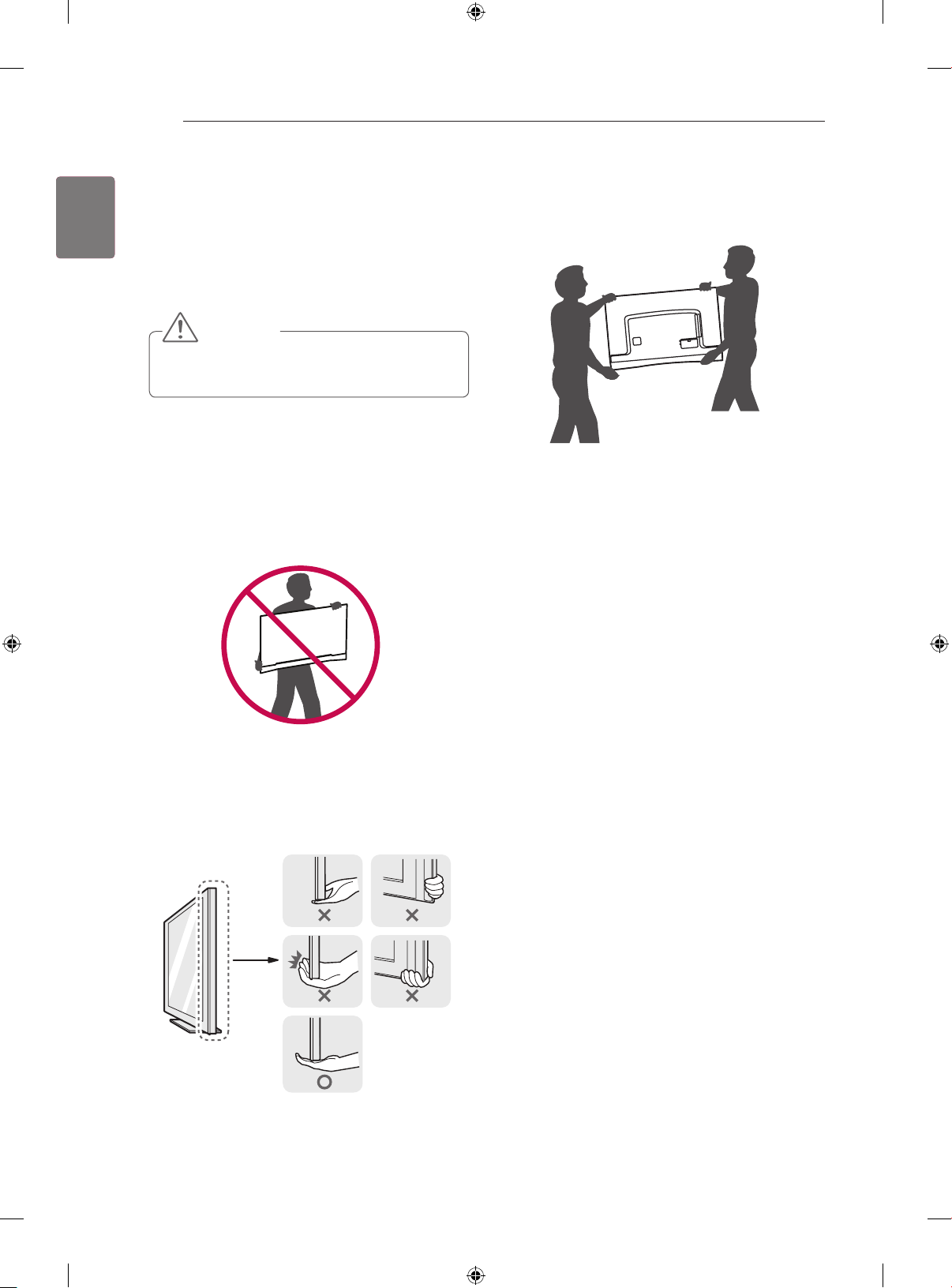
Lifting and moving the TV
Please note the following advice to prevent the TV from
being scratched or damaged and for safe transportation
regardless of its type and size.
CAUTION
y Avoid touching the screen at all times, as this may
result in damage to the screen.
It is recommended to move the TV in the box or
y
packing material that the TV originally came in.
Before moving or lifting the TV, disconnect the power
y
cord and all cables.
When holding the TV, the screen should face away
y
from you to avoid damage.
When transporting a large TV, there should be at
y
least 2 people.
When transporting the TV by hand, hold the TV as
y
shown in the following illustration.
When transporting the TV, do not expose the TV to
y
jolts or excessive vibration.
When transporting the TV, keep the TV upright,
y
never turn the TV on its side or tilt towards the left or
right.
Do not apply excessive pressure to cause flexing /
y
bending of frame chassis as it may damage screen.
Be sure to keep your TV upright instead of laying or
y
tilting it while moving the TV.
y Hold the top and bottom of the TV frame rmly. Make
sure not to hold the transparent part, speaker, or
speaker grill area. (Depending on model)
Page 19
ASSEMBLING AND PREPARING
10 cm
10 cm
10 cm
19
Assembling the AV cover
(Only EA98**, EA97**)
1. Please assemble the AV cover as shown.
AV cover
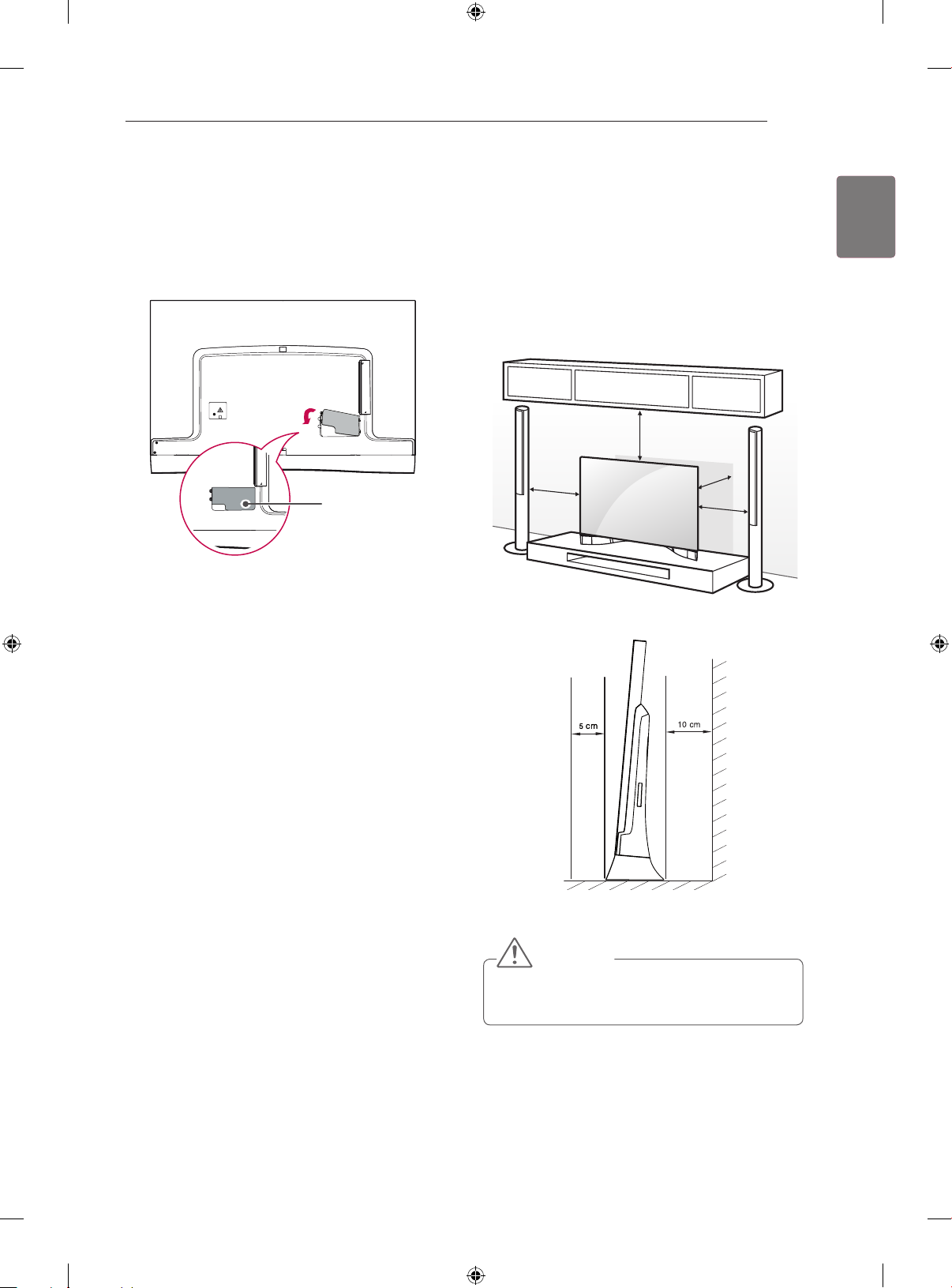
Mounting on a table
(Only EA98**, EA97**)
1 Lift and tilt the TV into its upright position on a table.
- Leave a 10 cm (minimum) space from the wall for
proper ventilation.
10 cm
10 cm
10 cm
10 cm
ENGLISH
ENG
2 Connect the power cord to a wall outlet.
CAUTION
y Do not place the TV near or on sources of heat, as
this may result in fire or other damage.
Page 20
20
ASSEMBLING AND PREPARING
ENGLISH
ENG
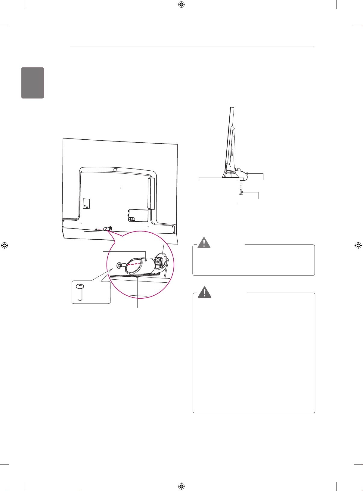
Securing the TV to a table
(Depending on model)
Fix the TV to a table to prevent from tilting forward, damage, and potential injury.
1 Install fall prevention band and cable management
accessories.
Cable Management
2 To secure the TV to a table, insert and tighten
a screw on the rear of the stand.
Fall prevention band
Fall prevention band
fixing screw
(*Not Provided)
WARNING
y To prevent TV from falling over, the TV should be
securely attached to the floor/wall per installation
instructions. Tipping, shaking, or rocking the TV
may cause injury.
1 EA
M4 x L20
Fall prevention band
WARNING
y If a television is not positioned in a sufficiently
stable location, it can be potentially hazardous
due to falling. Many injuries, particularly to
children, can be avoided by taking simple
precautions such as:
» Using cabinets or stands recommended by
the manufacturer of the television.
» Only using furniture that can safely support
the television.
» Ensuring the television is not overhanging
the edge of the supporting furniture.
» Not placing the television on tall furniture (for
example, cupboards or bookcases) without
anchoring both the furniture and the television to a suitable support.
» Not standing the televisions on cloth or other
materials placed between the television and
supporting furniture.
» Educating children about the dangers of
climbing on furniture to reach the television
or its controls.
Page 21
ASSEMBLING AND PREPARING
A
21
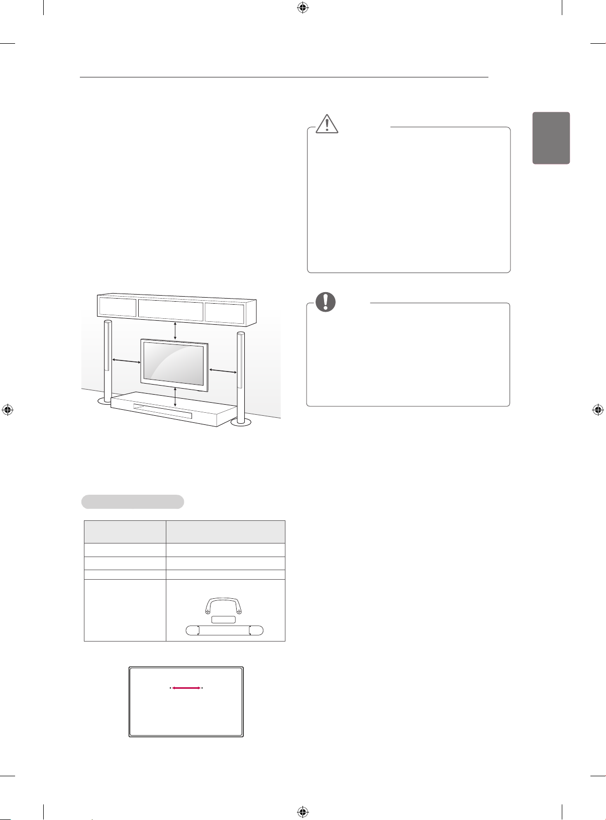
Mounting on a wall
(Only EA87**)
Attach an optional wall mount bracket at the rear of the
TV carefully and install the wall mount bracket on a solid
wall perpendicular to the oor. When you attach the
TV to other building materials, please contact qualied
personnel.
LG recommends that wall mounting be performed by a
qualied professional installer.
We recommend the use of LG’s wall mount bracket.
When you do not use LG’s wall mount bracket,
please use a wall mount bracket where the device is adequately secured to the wall with enough space to allow
connectivity to external devices.
10 cm
10 cm
10 cm
10 cm
CAUTION
yDisconnect the power first, and then move or
install the TV. Otherwise electric shock may
occur.
yIf you install the TV on a ceiling or slanted wall,
it may fall and result in severe injury. Use an
authorized LG wall mount and contact the local
dealer or qualified personnel.
yDo not over tighten the screws as this may cause
damage to the TV and void your warranty.
yUse the screws and wall mounts that meet the
VESA standard. Any damages or injuries by
misuse or using an improper accessory are not
covered by the manufacturer’s warranty.
NOTE
yUse the screws that are listed on the VESA
standard screw specifications.
yThe wall mount kit includes an installation manual
and necessary parts.
yThe length of screws may differ depending on the
wall mount. Make sure to use the proper length.
yFor more information, refer to the manual
supplied with the wall mount.
ENGLISH
ENG
Make sure to use screws and wall mount bracket that
meet the VESA standard. Standard dimensions for the
wall mount kits are described in the following table.
Wall Mounting Bracket
Model 55EA87**-TA
VESA (A) 210
Standard screw M6
Number of screws 2
Wall mount bracket OSW10F
Page 22
22
ASSEMBLING AND PREPARING / VIDEO CALL CAMERA
ENGLISH
ENG
Tidying cables
(Only EA98**, EA97**)
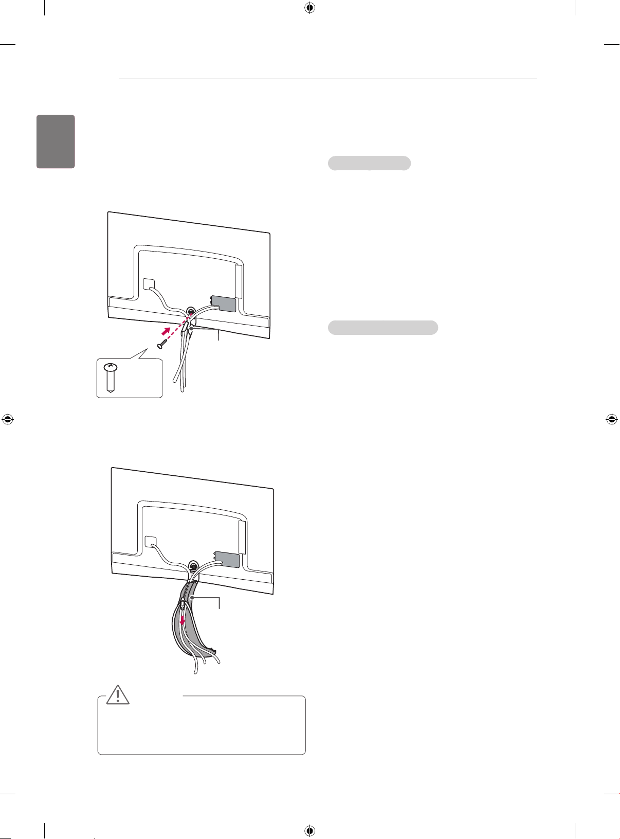
1 Fix the Cable Management with screw and arrange
the cables.
Cable Management
1 EA
M4 x L20
2 Wrap the arranged cables with the Cable Band.
3 Pull the zip down.
VIDEO CALL CAMERA
Product Handling
Do not let the camera get wet. Liquid getting into the
y
camera could cause a short circuit.
Wipe the camera gently with a dry cloth to remove any
y
dust or dirt. If the product is very dirty, spray a mild
detergent on the cloth first.
Do not clean with thinner, alcohol, benzene or any
y
other volatile agent.
These may damage the product’s surface or affect its
operation.
Do not disassemble, repair or alter the product.
y
Incorrect disassembly may cause a fire, electric shock,
or injury.
Do not shake the camera.
y
Do not pull on the cable.
y
Installation Instructions
Make sure you have enough space for connections
y
when installing the product.
Do not install in a dusty, dirty or moist area.
y
Do not install in direct sunlight or near a heat source.
y
Magnetic objects, such as speakers, may interfere with
y
the camera’s operation.
Install the product in a place with moderate
y
temperature and humidity. The recommended
temperature range is 0 °C to 40 °C.
Strong electromagnetic waves from other devices
y
could interfere with the camera’s operation.
Remove all the protective plastic bags (Vinyl) before
y
use.
Cable Band
CAUTION
y Do not move the TV by holding the Cable Manage-
ment and Cable Band, as the Cable Management
and Cable Band may break, and injuries and damage to the TV may occur.
The product and company names contained in this
manual may or may not be registered trademarks
or copyrights, and are only used for identification or
explanatory purposes. All trademarks reserved.
Page 23
VIDEO CALL CAMERA
23
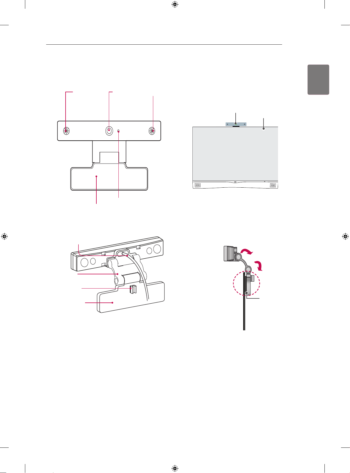
Overview
Microphones
Stand
Lens
Activity Indicator
Microphones
Attaching the video call camera
1 Unfold the stand and put it on the top center of the
TV set.
Video Call Camera
TV
2 Bend the stand of the video call camera. Attach the
stand of the video call camera to the back of the
display with a Velcro tape.
ENGLISH
ENG
USB Cable
Stand-Arm
Stand-Cable
holder
Stand-Bottom
Video Call Camera
Velcro tape
TV
Page 24
24
VIDEO CALL CAMERA / MAKING CONNECTIONS
ENGLISH
ENG
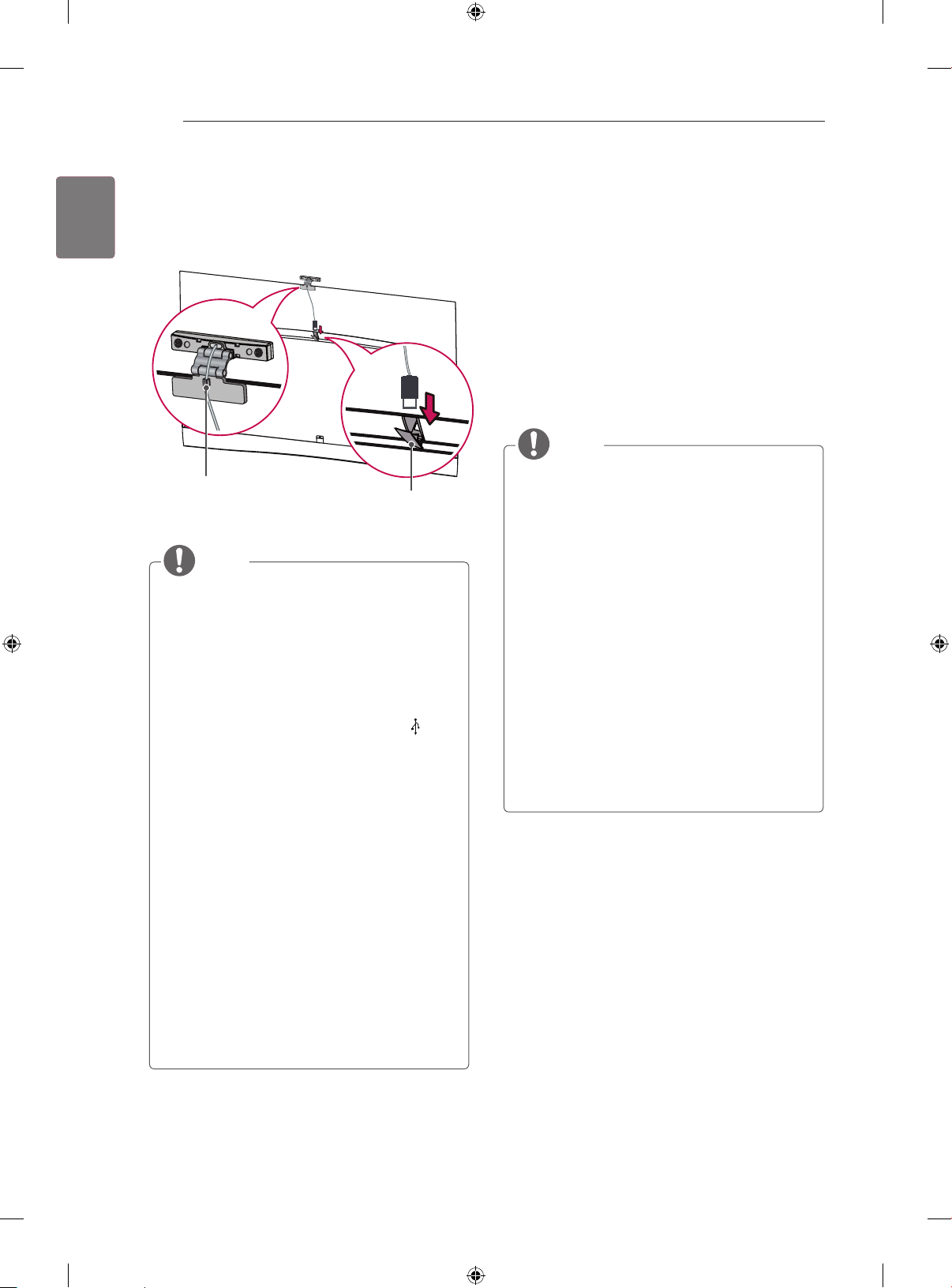
3 Insert the video call camera’s cable into the Stand-
Cable holder. Please open the USB Camera Cover
for video call camera’s cable connection.The camera
shall be connected to the CAM terminal as shown.
(Image shown may differ from your TV.)
Stand-Cable holder
USB Camera cover
NOTE
yFor the best quality video and audio outputs,
install the camera on the top-center of your TV.
ySet up with the television switched off.
yWhen using external speakers, allow sufficient
space between the microphones and the
speakers.
yThe TV must be connected to a network for
to work.
yMake sure to connect the video call camera cable
to the CAM port with the USB trident logo
the cable facing the front.
yFor best results when using external speakers,
only use the front right/left (stereo)
speakers when using.
When making a video call with using a PC,
y
the software version for Windows should be 4.2
or newer.
(Visit the homepage (www.com) for operating
systems other than Windows, e.g. OS X, Linux,
etc.)
yVideo calls can not be made to a Mac that runs
2.8 or lower.
Content can be changed or deleted depending on
y
Content Provider.
yPlease visit the content providers web site for
specific information on their services.
yThe software update screen will automatically
appear when an update is available.
yFor some models, you cannot use input devices
such as a keyboard and mouse while
using (premium content).
on
MAKING CONNECTIONS
This section on MAKING CONNECTIONS mainly uses
diagrams for the EA98** models.
Connect various external devices to the TV and switch input modes to select an external device. For more information on external device’s connection, refer to the manual
provided with each device.
Available external devices are: HD receivers, DVD players, VCRs, audio systems, USB storage devices, PC,
gaming devices, and other external devices.
NOTE
y The external device connection may differ from
the model.
y Connect external devices to the TV regardless of
the order of the TV port.
y If you record a TV program on a DVD recorder or
VCR, make sure to connect the TV signal input
cable to the TV through a DVD recorder or VCR.
For more information of recording, refer to the
manual provided with the connected device.
y Refer to the external equipment’s manual for
operating instructions.
y If you connect a gaming device to the TV, use the
cable supplied with the gaming device.
y In PC mode, there may be noise associated
with the resolution, vertical pattern, contrast or
brightness. If noise is present, change the PC
output to another resolution, change the refresh
rate to another rate or adjust the brightness and
contrast on the PICTURE menu until the picture
is clear.
y In PC mode, some resolution settings may not
work properly depending on the graphics card.
Page 25
MAKING CONNECTIONS
ANTENNA/
CABLE
25
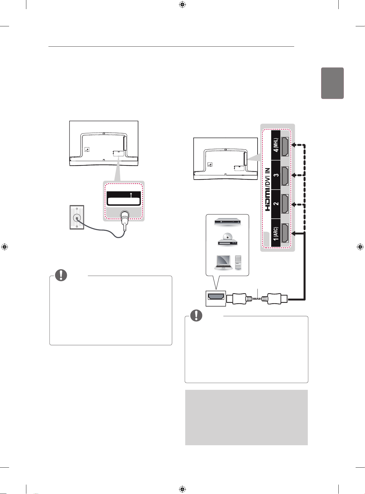
Antenna connection
Connect the TV to a wall antenna socket with an RF cable
(75 Ω).
IN
ANTENNA / CABLE
HDMI connection
Transmits the digital video and audio signals from an
external device to the TV. Connect the external device
and the TV with the HDMI cable as shown.
Choose any HDMI input port to connect. It does not
matter which port you use.
DVD / Bly-Ray / HD Cable Box
/ HD STB / PC
ENGLISH
ENG
NOTE
Use a signal splitter to use more than 2 TVs.
y
If the image quality is poor, install a signal
y
amplifier properly to improve the image quality.
If the image quality is poor with an antenna
y
connected, try to realign the antenna in the
correct direction.
An antenna cable and converter are not provided.
y
Supported DTV Audio:
y
MPEG, Dolby Digital, Dolby Digital Plus,
HE-AAC
(*Not Provided)
HDMI
NOTE
It is recommended to use the TV with the HDMI
y
connection for the best image quality.
Use the latest High Speed HDMI™ Cable with
y
CEC (Customer Electronics Control) function.
High Speed HDMI™ Cables are tested to carry an
y
HD signal up to 1080p and higher.
Supported HDMI Audio format :
y
Dolby Digital (32 KHz / 44.1 KHz / 48 KHz), DTS
(44.1 KHz / 48 KHz), PCM (32 KHz / 44.1 KHz /
48 KHz / 96 KHz / 192 KHz)
ARC (Audio Return Channel)
An external audio device that supports
y
SIMPLINK and ARC must be connected using
HDMI/DVI IN 1 (ARC) port.
When connected with a high-speed HDMI cable,
y
the external audio device that supports ARC
outputs optical SPDIF without additional optical
audio cable and supports the SIMPLINK function.
Page 26
MAKING CONNECTIONS
VIDEO
AUDIO
L R
IN
COMPONENT
YP
B
AUDIOAVP
R
VIDEO
AV
26
ENGLISH
ENG
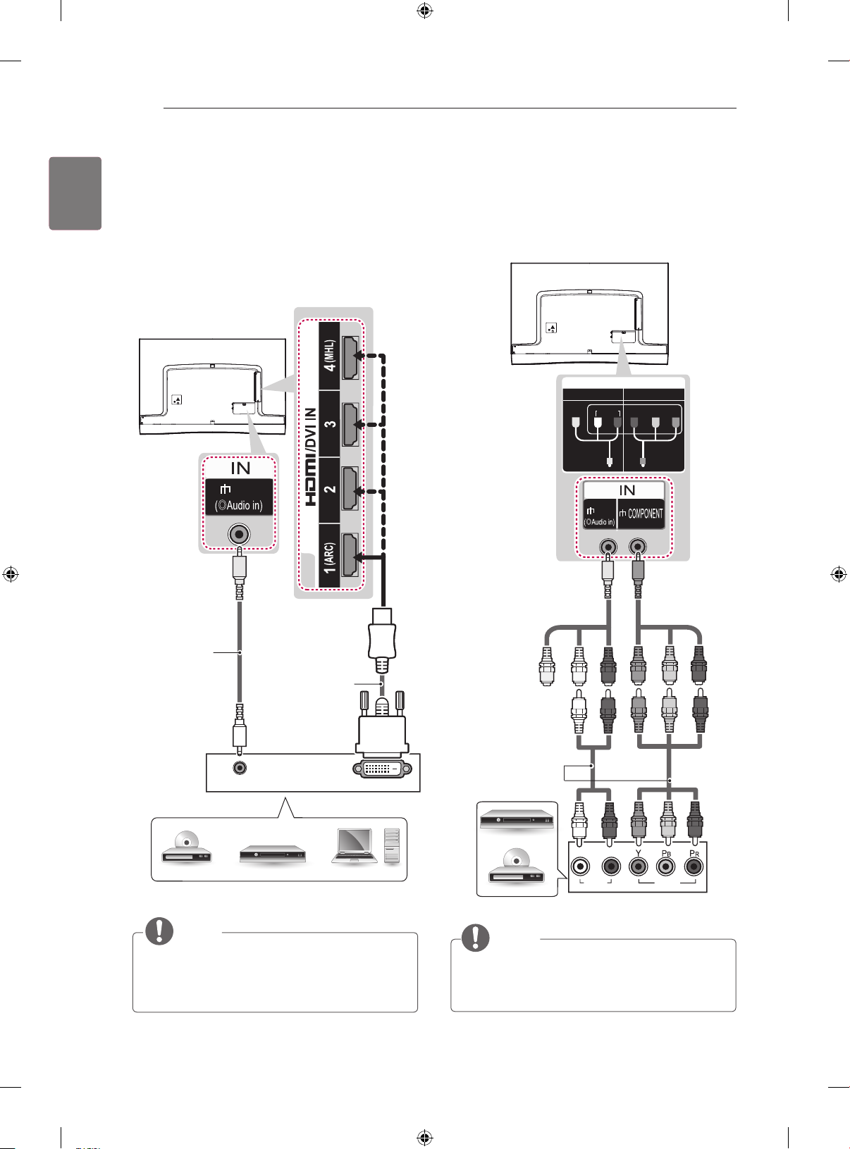
DVI to HDMI connection
Transmits the digital video signal from an external device
to the TV. Connect the external device and the TV with
the DVI-HDMI cable as shown. To transmit an audio
signal, connect an audio cable.
Choose any HDMI input port to connect. It does not
matter which port you use.
AV
(*Not Provided)
Component connection
Transmits analogue video and audio signals from an
external device to the TV. Connect the external device
and the TV with a component gender cable as shown.
(Use the composite
YELLOW
video cable
provided.)
YELLOW
WHITE WHITE
GREEN
(Use the
component video
cable provided.)
GREEN GREEN
RED RED
BLUE BLUE
RED
(*Not Provided)
AUDIO OUT
DVD / Blu-Ray / HD Cable Box / PC
NOTE
Depending on the graphics card, DOS mode may
y
not work if a HDMI to DVI Cable is in use.
When using the HDMI / DVI cable, Single link is
y
only supported.
DVI OUT
(*Not Provided)
RED
GREEN
BLUE
WHITE
DVD / Blu-Ray / HD Cable Box
NOTE
y If cables are not installed correctly, it could cause
this image to display in black and white or with
distorted colours.
RED
RED
Page 27
MAKING CONNECTIONS
27
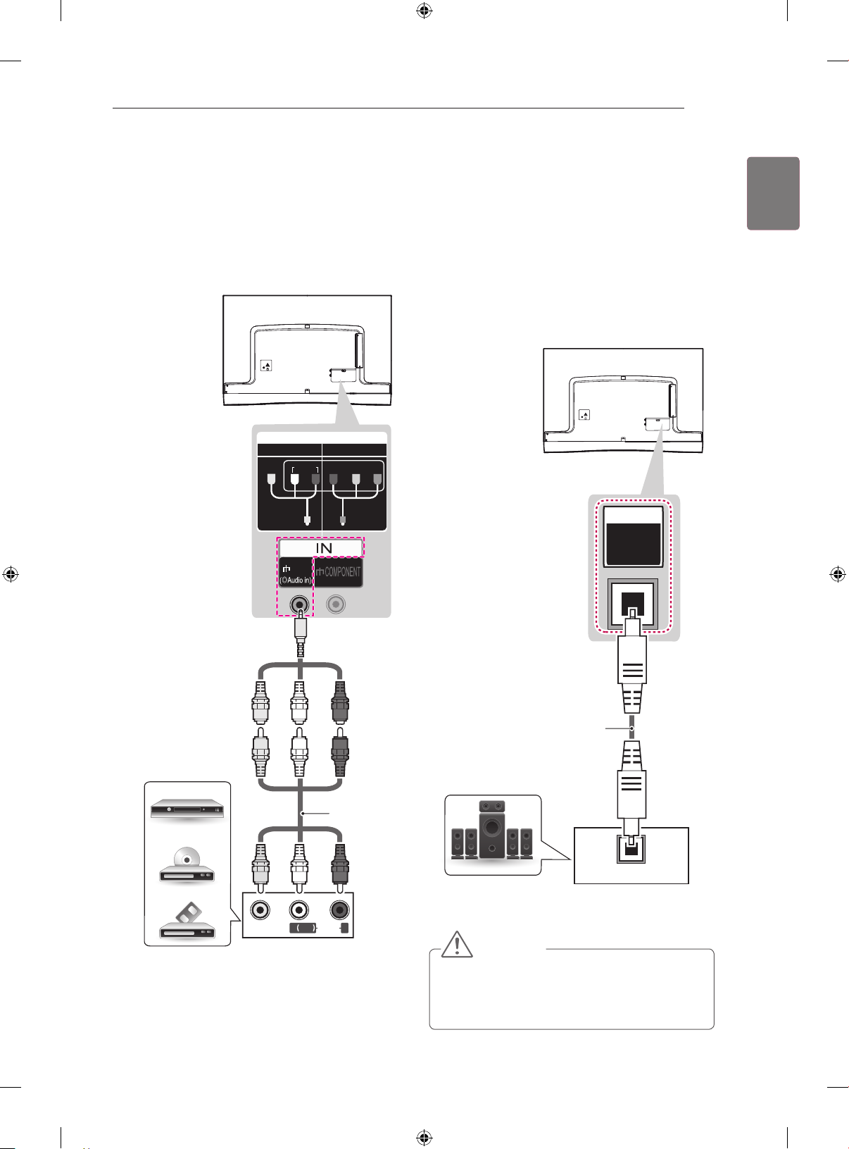
Composite connection
Transmits analogue video and audio signals from an
external device to the TV. Connect the external device
and the TV with a composite gender cable as shown.
IN
COMPONENT
VIDEO
COMPONENT
AUDIOAVP
AV
Y
P
B
YP
B
R
Audio connection
You may use an external audio system instead of the
built-in speaker.
Digital optical audio connection
Transmits a digital audio signal from the TV to an external
device. Connect the external device and the TV with the
optical audio cable as shown.
OUT
OPTICAL
DIGITAL
AUDIO
ENGLISH
ENG
(Use the composite video
YELLOW
cable provided.)
VCR / DVD / Blu-Ray /
HD Cable Box
VIDEO
YELLOW
YELLOW
YELLOW
( )
MONO
L R
WHITE WHITE
RED
RED
(*Not Provided)
WHITE
RED
AUDIO
(*Not Provided)
OPTICAL
Digital Audio System /
AUDIO IN
Canvas Speaker
(Only EA88**)
CAUTION
y Do not look into the optical output port. Looking at
the laser beam may damage your vision.
y Audio with ACP (Audio Copy Protection) function
may block digital audio output.
Page 28
MAKING CONNECTIONS
28
ENGLISH
ENG
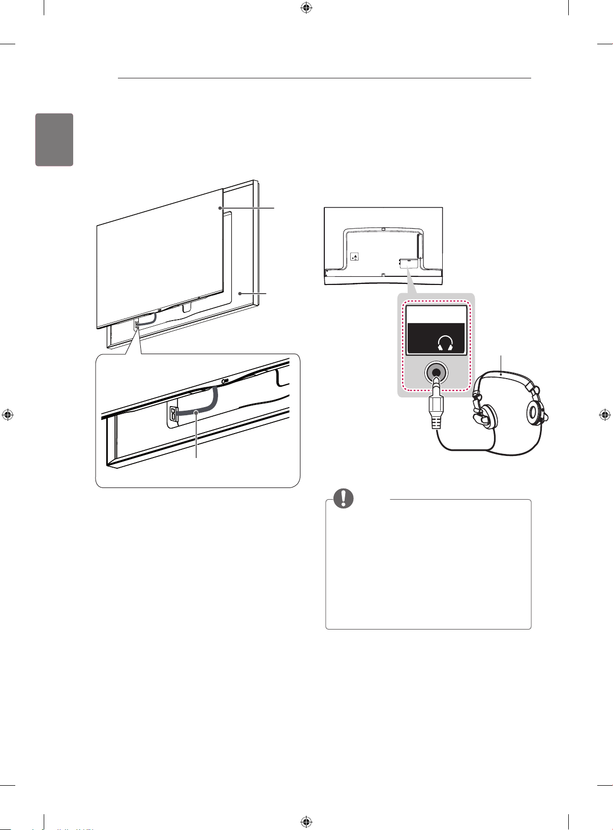
Canvas speaker connection
(Only EA88**)
Connect the Canvas speaker and the TV set with the
optical cable as shown.
TV
Canvas
Speaker
(Use the Canvas
Speaker provided.)
Headphone connection
Transmits the headphone signal from the TV to an
external device. Connect the external device and the
TV with the headphone as shown.
OUT
Ext.Speaker /
H/P
(*Not Provided)
Optical cable
(Use the Optical cable provided.)
NOTE
y AUDIO menu items are disabled when connect-
ing a headphone.
y When changing AV MODE with a headphone
connected, the change is applied to video but not
to audio. (Depending on model)
y Optical Digital Audio Out is not available when
connecting a headphone.
y Headphone impedance: 16 Ω
y Max audio output of headphone: 0.627 mW to
1.334 mW
y Headphone jack size: 0.35 cm
Page 29
MAKING CONNECTIONS
2
3
/
(ARC)
29
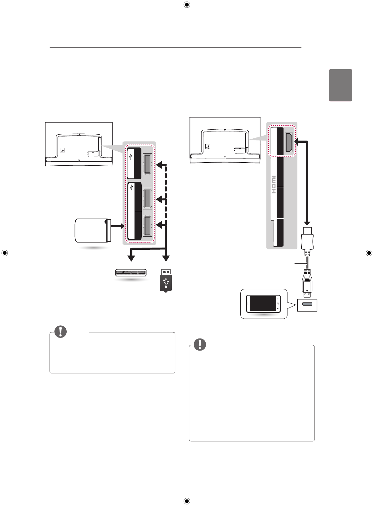
USB connection
Connect a USB storage device such as a USB flash
memory, external hard drive or a USB
memory card reader to the TV and access the Smart
Share menu to use various multimedia files.
3
USB IN
2
USB IN
HDD IN
(USB 3.0 IN)
1
MHL connection
Mobile High-definition Link (MHL) is an interface for
transmitting digital audiovisual signals from mobile
phones to television sets.
4(MHL)
DVI IN
ENGLISH
ENG
HDD
(*Not Provided)
HUB
(*Not Provided)
(*Not Provided)
NOTE
Some USB Hubs may not work. If a USB device
y
connected using a USB Hub is not detected,
connect it to the USB IN port on the TV directly.
Connect the external power source if your USB is
y
needed.
USB
MHL passive cable
(*Not Provided)
Mobile phone
NOTE
Connect the mobile phone to the HDMI/DVI IN
y
4(MHL) port to view the phone screen on the TV.
The MHL passive cable is needed to connect the
y
TV and a mobile phone.
This only works for the MHL-enabled phone.
y
Some applications can be operated by the remote
y
control.
For some mobile phones supporting MHL, you
y
can control with the magic remote control.
Remove the MHL passive cable from the TV
y
when:
» the MHL function is disabled
» your mobile device is fully charged in standby
mode
Page 30
REMOTE CONTROL
INFO
30
ENGLISH
ENG
REMOTE CONTROL
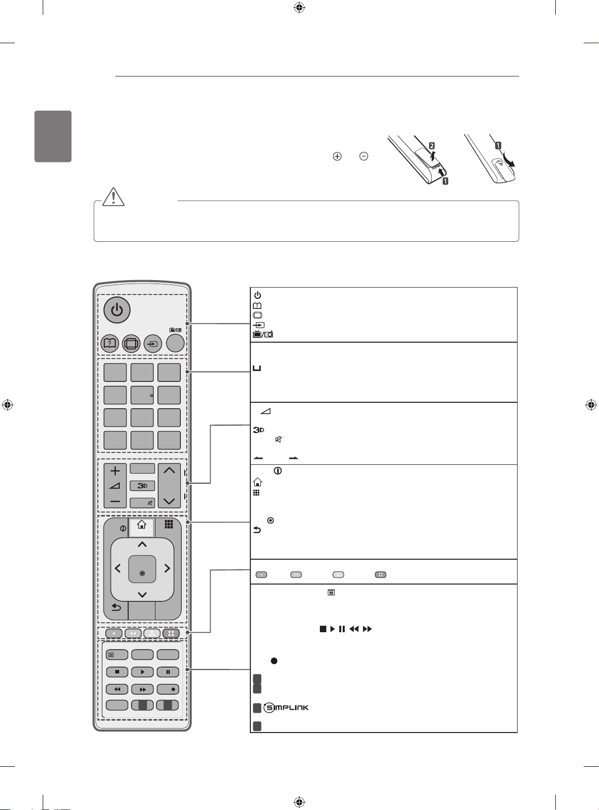
The descriptions in this manual are based on the buttons on the remote control.
Please read this manual carefully and use the TV correctly. To replace batteries,
open the battery cover, replace batteries (1.5 V AAA) matching the
to the label inside the compartment, and close the battery cover. To remove the batteries, perform the installation actions in reverse.
CAUTION
Do not mix old and new batteries, as this may damage the remote control.
y
In Analogue TV and some countries, some remote control buttons may not work.
y
The remote control will not be included for all sales market.
y
Make sure to point the remote control toward the remote control sensor on the TV.
(Depending on model)
(POWER) Turns the TV on or off.
(User Guide) Sees User Guide.
RATIO Resizes an image.
RATIO
INPUT
1 2 3
4 5 6
7 809
LIST
FAV
MUTE
INFO
SMART
OK
TV /
RAD
Q.VIEW
P
MY APPS
P
A
G
E
INPUT Changes the input source.
TV/RAD Selects Radio, TV and DTV programme.
Number buttons Enters numbers.
Alphabet buttons Enters letters. (Depending on model)
(Space) Opens an empty space on the screen keyboard. (Depending
on model)
LIST
Accesses the saved programme list.
Q.VIEW
Returns to the previously viewed programme.
- Adjusts the volume level.
+
FAV Accesses your favourite programme list.
Uses for viewing 3D video.
Mutes all sounds.
MUTE
ꕌPꕍ Scrolls through the saved programmes.
PAGE Moves to the previous or next screen.
Views the information of the current programme and screen.
SMART
My APPS
Accesses the HOME menu.
Shows the list of Apps.
Navigation Buttons (up/down/left/right)
tions.
OK Selects menus or options and confirms your input.
BACK Returns to the previous level.
GUIDE Shows programme guide.
Clears on-screen displays and returns to TV viewing.
ExIT
Colour buttons These access special functions in some menus.
(
: Red, : Green, : Yellow, : Blue)
and ends
or
Scrolls through menus or op-
BACK
LIVE TV
SETTINGS
GUIDE
1 2
EXIT
SUBTITLE
Q.MENUT.OPTTEXT
REC
TELETExT buttons(
TExT, T.OPT) These buttons are used for teletext.
SUBTITLE Recalls your preferred subtitle in digital mode.
Q.MENU
LIVE TV
Accesses the Quick menus.
Returns to the LIVE TV.
Control buttons ( ) Controls the Premium contents, Time
Machine
(USB or SIMPLINK or Time Machine
Ⅱ
or SmartShare menus or the SIMPLINK compatible devices
Ⅱ).
REC Uses to adjust Time Machine menu.
SETTINGS Accesses the main menus.
1
AV MODE Selects an AV mode. (Depending on model)
AD By pressing the AD button, audio descriptions function will be
1
enabled. (Depending on model)
Accesses the AV devices connected with the HDMI cable
2
through HDMI-CEC.Opens the SIMPLINK menu. (Depending on model)
2
APP/* Select the MHP TV menu source. (Depending on model)
Page 31
REMOTE CONTROL
RATIO INPUT
TV/
RAD
1
.,;@
2
abc3 def
4
ghi
5
jkl
6
mno
7
pqrs8 tuv
0
9
wxyz
[
LIST
Q.VIEW
FAV
MUTE
P
P
A
G
E
EXIT
OK
SETTINGS
INFO
GUIDE
REC
MY APPS
LIVE TV
SUBTITLE
MUTE
FAV
SLEEP
TV/
RAD
MY APPS
LIVE TV
REC
SMART
INFO
31
(Depending on model)
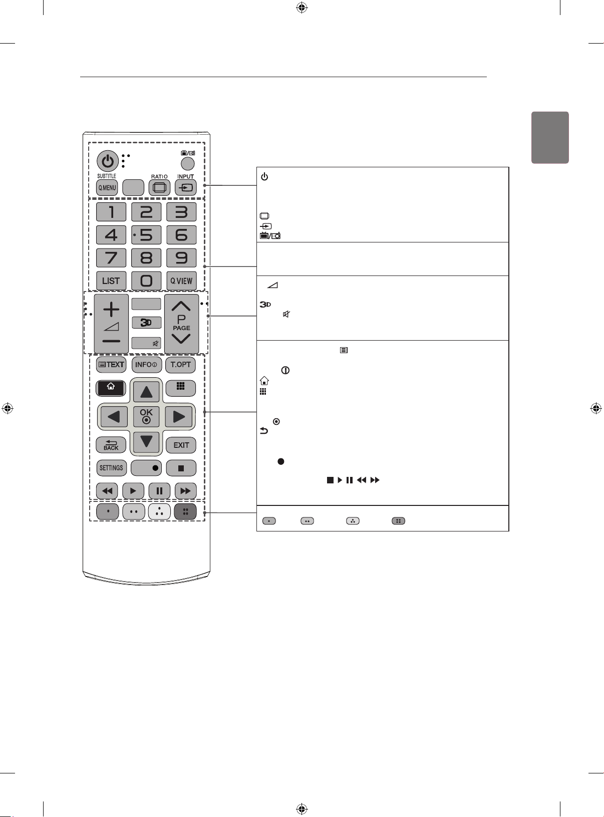
(POWER) Turns the TV on or off.
SUBTITLE Recalls your preferred subtitle in digital mode.
Q. MENU Accesses the quick menus.
GUIDE Shows programme guide.
RATIO Resizes an image.
INPUT Changes the input source.
TV/RAD Selects Radio, TV and DTV programme.
Number buttons Enters numbers.
LIST Accesses the saved programme list.
Q.VIEW Returns to the previously viewed programme.
- Adjusts the volume level.
+
FAV Accesses your favourite programme list.
Uses for viewing 3D video.
MUTE Mutes all sounds.
ꕌPꕍ Scrolls through the saved programmes.
ꕌPAGEꕍ Moves to the previous or next screen.
TELETExT BUTTONS ( TExT, T.OPT)
teletext.
Navigation buttons (up/down/left/right) Scrolls through menus
or options.
OK
ExIT
SETTINGS
REC
LIVE TV
Control buttons ( ) Controls the Premium contents,
Time Machine Ⅱ or SmartShare menus or the SIMPLINK compatible
devices (USB or SIMPLINK or Time Machine
Colour buttons These access special functions in some menus.
( : Red, : Green, : Yellow, : Blue)
Views the information of the current programme and screen.
SMART
My APPS
BACK
Accesses the HOME menu.
Shows the list of Apps.
Selects menus or options and confirms your input.
Returns to the previous level.
Clears on-screen displays and returns to TV viewing.
Accesses the main menus.
Uses to adjust Time Machine menu.
Returns to the LIVE TV.
These buttons are used for
Ⅱ).
ENGLISH
ENG
Page 32
MAGIC REMOTE CONTROL FUNCTIONS
P
/Q.MENU
32
ENGLISH
ENG
MAGIC REMOTE CONTROL FUNCTIONS
When the message "Magic remote control battery is low. Change the battery." is
displayed, replace the battery.
To replace batteries, open the battery cover, replace batteries (1.5 V AA) matching
ends to the label inside the compartment, and close the battery cover. Be sure to point
the magic remote control toward the remote control sensor on the TV.
To remove the batteries, perform the installation actions in reverse.
CAUTION
Do not mix old and new batteries, as this may damage the remote control.
y
In Analogue TV and some countries, some remote control buttons may not work.
y
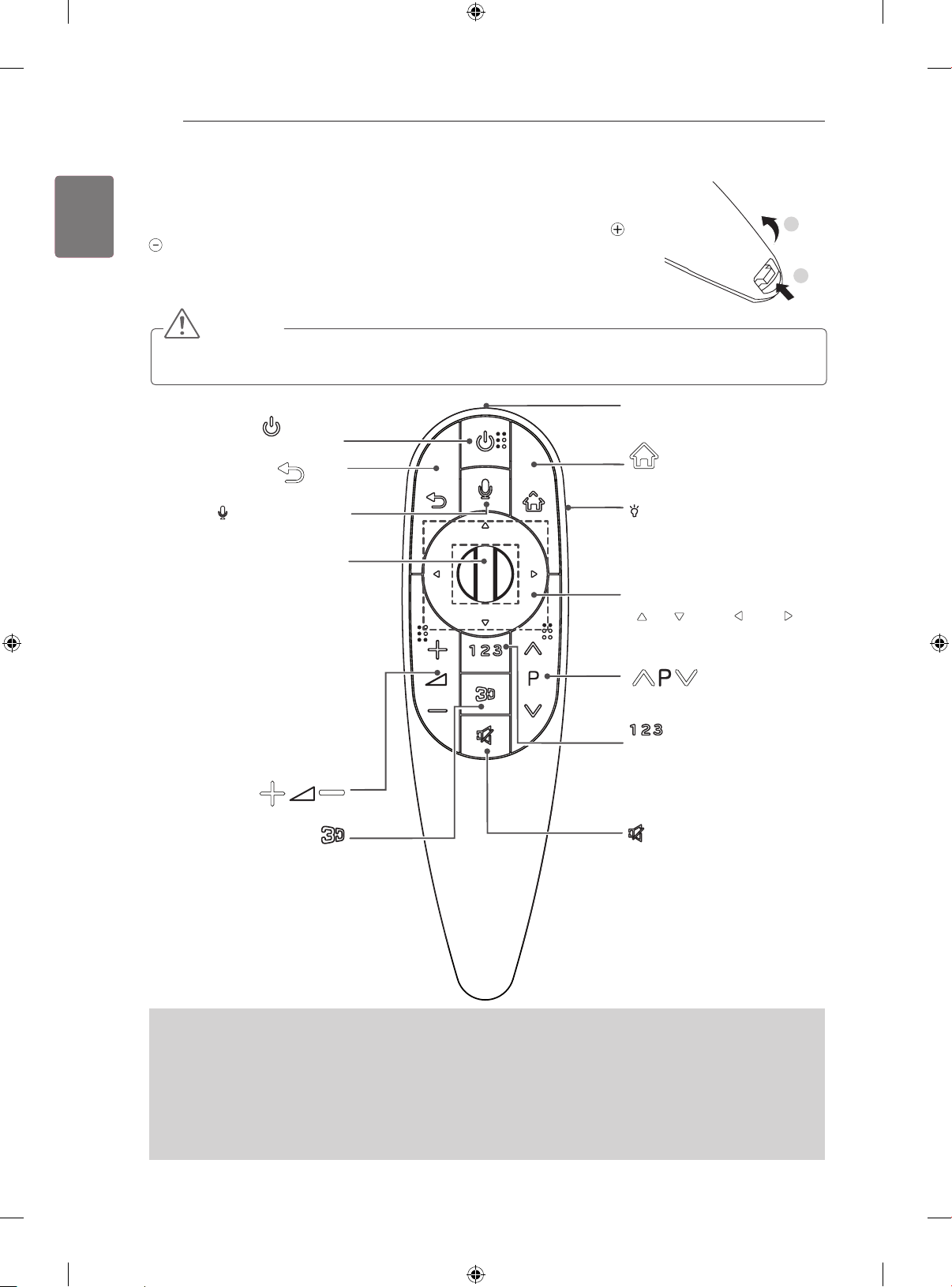
(POWER)
Turns the TV on or off.
Returns to the previous level.
BACK
(Voice recognition)
(Depending on model)
Wheel(OK)
Selects menus or options and
confirms your input.
Scrolls through the saved pro-
grammes.
If you press the navigation button
while moving the pointer on the
screen, the pointer disappears,
and the Magic Remote Control
works as a regular remote control.
To display the pointer again, shake
the Magic Remote Control from
side to side.
Adjusts the volume level.
Used for viewing 3D video.
BACK
SMART
/Q.MENU
and
Pointer (RF transmitter)
SMART
2
1
Accesses the HOME menu.
LIGHTING ON/OFF
Turns the light on and off.
If you set it to ON, the light automatically turns off in 5 seconds
Navigation buttons
(
UP DOWN LEFT
RIGHT )
Scrolls through menus or options.
Scrolls through the saved programmes.
Accesses the quick menus.
Accesses the Screen Remote including number button and colour
button.
(MUTE)
Mutes all sounds.
Voice recognition (Depending on model)
Network connection is required to use the voice recognition function.
The recognition rate may vary depending on the user’s characteristics (voice, pronunciation, intonation and speed)
and the environment (noise and TV volume).
1. Press the Voice recognition button.
2. Speak when the voice display window appears on the left of the TV screen.
• The voice recognition may fail when you speak too fast or too slow.
• Use the Magic remote control no further than 10 cm from your face.
Page 33
MAGIC REMOTE CONTROL FUNCTIONS
HOME
33
Registering Magic Remote Control
It is necessary to ‘pair’ (register) the magic remote control to your TV before it will work.
How to register the Magic Remote Control
1 To register automatically, turn the
TV on and press the Wheel(OK)
button. When registration is
completed, the completion
message appears on the screen.
2 If registration fails, turn the TV
off and back on, then press the
Wheel(OK) button to complete
registration.
How to re-register the Magic Remote Control
BACK
SMART
1 Press and hold the BACK and
SMART buttons together for 5
seconds to reset, then register it
by following “How to register the
Magic Remote Control” above.
2 To re-register the Magic Remote
Control, press and hold the
BACK button for 5 seconds
toward the TV. When registration
is completed, the completion
message appears on the screen.
More
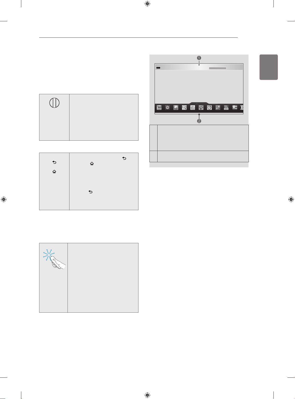
If you press Wheel(OK) on the Magic Remote
Control, the following screen appears.
1
Shows information about the current programme
and screen.
You can select More Menu.
2
Precautions to Take when Using
the Magic Remote Control
ENGLISH
ENG
How to use Magic Remote Control
1 If the pointer disappears, move
the remote control slightly to left
or right. Then, it will automatically
appear on the screen.
» If the pointer has not been
used for a certain period of time, it
will disappear.
2 You can move the pointer by
aiming the Pointer Receiver of the
remote control at your TV then
move it left, right, up or down.
» If the pointer does not work
properly, leave the remote control
for 10 seconds then use it again.
y Use the Magic Remote Control within the maxi-
mum communication distance (10 m). Using the
Magic Remote Control beyond this distance, or
with an object obstructing it, may cause a communication failure.
y A communication failure may occur due to nearby
devices. Electrical devices such as a microwave
oven or wireless LAN product may cause interference, as these use the same bandwidth (2.4 GHz)
as the Magic Remote Control.
y The Magic Remote Control may be damaged
or may malfunction if it is dropped or receives a
heavy impact.
y Take care not to bump into nearby furniture or oth-
er people when using the Magic Remote Control.
y Manufacturer and installer cannot provide service
related to human safety as the applicable wireless
device has possibility of electric wave interference.
y It is recommended that an Access Point (AP) be
located more than 1 m away from the TV. If the
AP is installed closer than 1 m, the Magic Remote
Control may not perform as expected due to frequency interference.
Page 34
USING THE USER GUIDE
34
ENGLISH
ENG
USING THE USER GUIDE
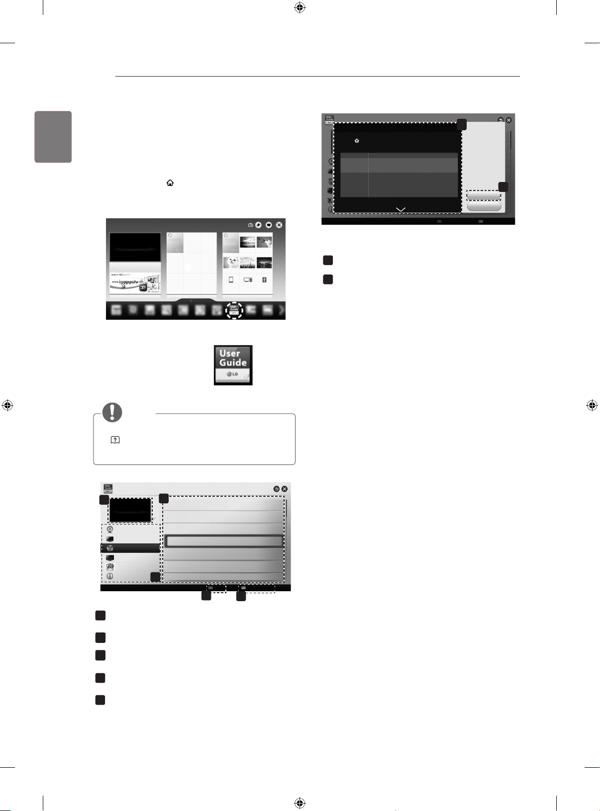
User Guide allows you to more easily access the detailed TV information.
1 Press the SMART button to access the Smart Home
menu.
2 Select User Guide and press Wheel(OK).
User Guide
OPTION > To set language
SMART Settings OPTION Language
Selects Menu Language and Audio Language displayed on the screen.
Menu Language
Selects a language for the display text.
[In Digital Mode Only]
Audio Language
When watching a digital broadcast containing several audio
languages, you can select the language you want.
[In Digital mode Only]
Use the Subtitle function when two or more subtitle
Subtitle
languages are broadcast.
Language
✎ If subtitle data in a selected language is not broadcast,
the default language subtitle will be displayed.
Shows the description of the selected menu.
1
You can use ꕌ/ꕍto move between pages.
Moves to the selected menu directly from the User
2
Guide.
1
Try Now
index
2
Close
Online User Guide
NOTE
y You can also access the User Guide by pressing
(User Guide) in the remote control.
(Depending on model)
User Guide
1
PROGRAMME Setting
PICTURE, SOUND Setting
OPTION
LG SMART Function
Advanced Function
Information
Shows the current watching programme or input
1
source screen.
Allows to select the category you want.
2
Allows to select the item you want.
3
You can use ꕌ/ꕍto move between pages.
Allows to browse the description of the function you
4
want from the index.
Provides the detailed information on the functions
5
of LG Smart TV when the Internet is connected.
(It may not be available depending on the country/
language.)
3
To use input device
To set time options
To set TV lock options
To set language
To set country
To set Magic remote control
To set other options
2
Index
4
Online User Guide
5
Page 35
MAINTENANCE
35
MAINTENANCE
Cleaning Your TV
Clean your TV regularly to keep the best performance and to extend the product lifespan.
CAUTION
y Make sure to turn the power off and disconnect the power cord and all other cables first.
y When the TV is left unattended and unused for a long time, disconnect the power cord from the wall outlet to
prevent possible damage from lightning or power surges.
Screen, frame, cabinet and stand
To remove dust or light dirt, wipe the surface with a dry, clean, and soft cloth.
To remove major dirt, wipe the surface with a soft cloth dampened in clean water or a diluted mild
detergent. Then wipe immediately with a dry cloth.
CAUTION
y Avoid touching the screen at all times, as this may result in damage to the screen.
y Do not push, rub, or hit the surface with your fingernail or a sharp object, as this may result in
scratches on the screen and image distortions.
y Do not use any chemicals as this may damage the product.
y Do not spray liquid onto the surface. If water enters the TV, it may result in fire, electric shock, or malfunction.
ENGLISH
ENG
CAUTION
(Only EA98**)
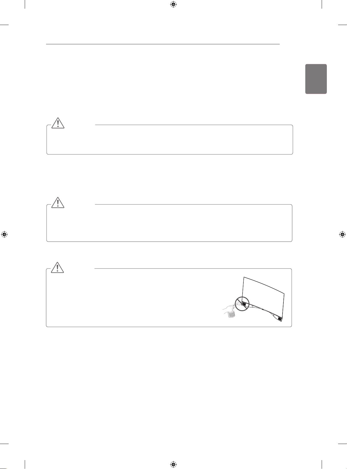
y When cleaning your TV, do not spray water directly on the left and right
speakers at the bottom of the TV.
y Do not let any water enter your TV and keep it dry.
» Otherwise, this may cause damage to the product, such as corrosion.
Power cord
Remove the accumulated dust or dirt on the power cord regularly.
Page 36
TROUBLESHOOTING
36
ENGLISH
ENG
TROUBLESHOOTING
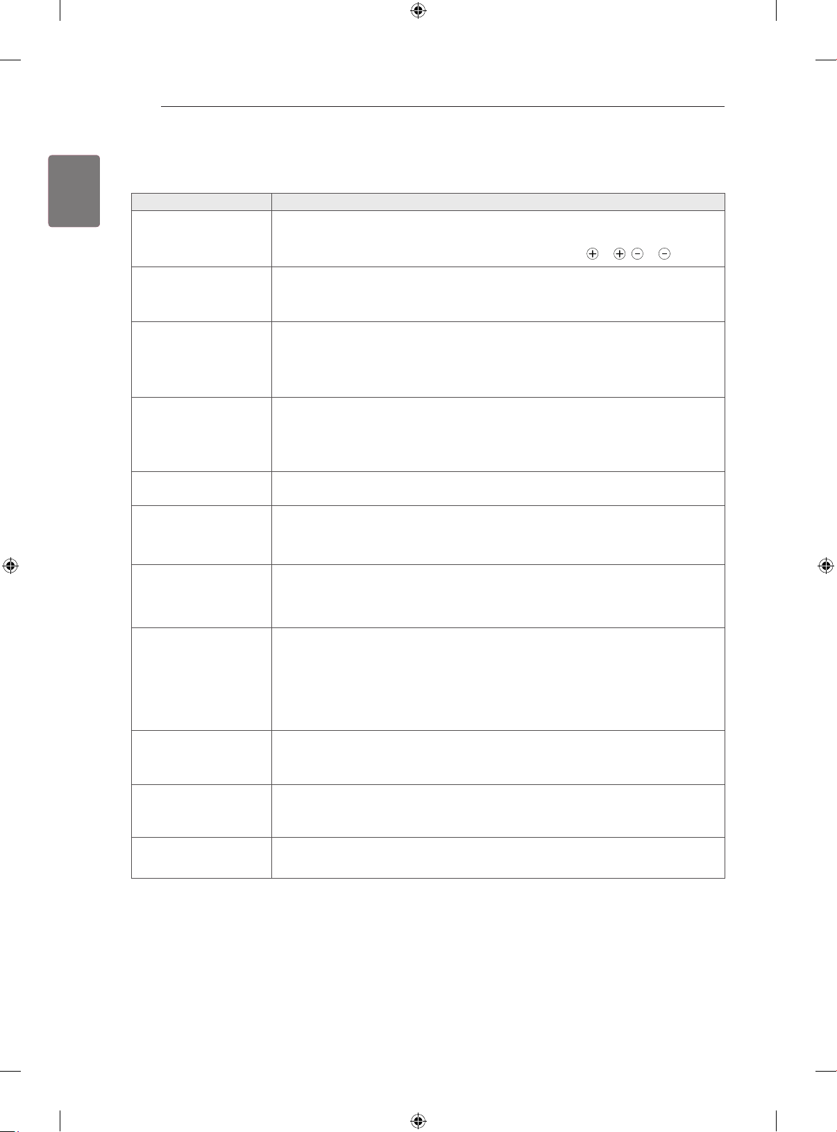
Problem Solution
Cannot control the TV with
the remote control.
No image display and no
sound is produced.
The TV turns off
suddenly.
When connecting to the
PC (HDMI/DVI), ‘No sig-
nal’ or ‘Invalid Format’ is
displayed.
If doesn’t start
If the Notification Window
is not displayed when a
call is received
If there’s echo (e.g. when
you hear your own voice
played back through the
speakers)
If you’re not able to receive
any video or if it is of low
quality
If the call ends abruptly
y Check the remote control sensor on the product and try again.
y Check if there is any obstacle between the product and the remote control.
y Check if the batteries are still working and properly installed (
y Check if the product is turned on.
y Check if the power cord is connected to a wall outlet.
y Check if there is a problem in the wall outlet by connecting other products.
y Check the power control settings. The power supply may be interrupted.
y Check if the Sleep Timer or Off Time feature is activated in the TIME settings.
y If there is no signal while the TV is on, the TV will turn off automatically after 15 minutes
of inactivity.
y Turn the TV off/on using the remote control.
y Reconnect the HDMI cable.
y Restart the PC with the TV on.
Check whether the Video Call Camera is properly connected to the USB port on the TV.
y
Check the network connection status.
y
Check that your status is not set as “Do not disturb”.
y
When using certain TV functions, incoming calls can’t be received
y
(e.g. during a software update, etc.).
Check ‘Privacy Settings’ is “Allow calls from people in my contact list only”.
y
Change the home theater audio setting to stereo rather than surround.
y
Reduce the speaker volume.
y
Too much echo in the room can decrease audio quality.
y
Test microphone using the ‘Echo / Sound Test Service’.
y
Internet or network congestion can degrade video quality.
y
Using wireless can also degrade video quality. We recommend using a wired internet
y
connection.
Screen quality can decrease when using Zoom-In. We recommend you use minimum
y
zoom during video calls.
Check whether the call quality information is marked as “critical”. If this is the case,
y
video quality can be degraded.
When certain TV functions are activated, the call may be disconnected. (e.g. Sleep
y
timer, etc.)
Do not unplug the Video Call Camera during a call.
y
to , to ).
If the menu does not
appear on the
Premium menu
Other issues
Connect the camera to your TV, then update the software. For details about how to
y
update the software, refer to your TV manual.
Issues may arise from network congestion of problems with the network. y For
y
further inquiries about functions, visit www.com.
Page 37
SPECIFICATIONS
0197
37
SPECIFICATIONS
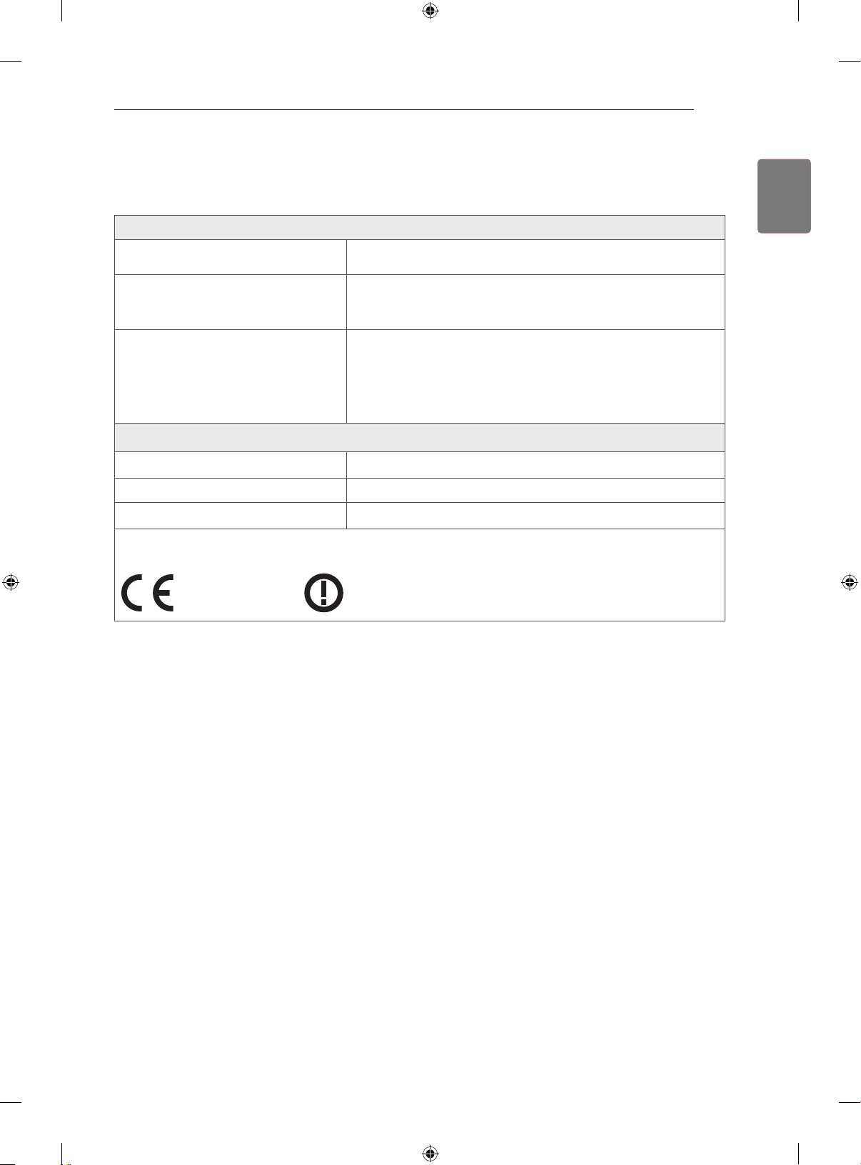
Wireless LAN module(TWFM-B006D) specification
Standard IEEE802.11a/b/g/n
2400 to 2483.5 MHz
Frequency Range
Output Power
(Max.)
Bluetooth module (BM-LDS401) specification
Standard Bluetooth Version 3.0
Frequency Range 2400 ~ 2483.5 MHz
Output Power (Max.) 10 dBm or lower
y Because band channel used by the country could be different, the user can not change or adjust the operating fre-
quency and this product is set for the regional frequency table.
5150 to 5250 MHz
5725 to 5850 MHz (for Non EU)
802.11a: 11 dBm
802.11b: 14 dBm
802.11g: 10.5 dBm
802.11n - 2.4GHz: 11 dBm
802.11n - 5GHz: 12.5 dBm
ENGLISH
ENG
Page 38
SPECIFICATIONS
38
ENGLISH
ENG
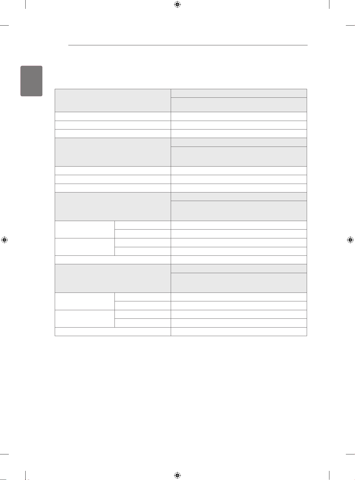
Product specifications may be changed without prior notice due to upgrade of product functions.
For the power supply and power consumption, refer to the label attached to the product.
55EA98
**
MODEL
Dimensions (W x H x D) (mm) 1227 x 798.5 x 192
Weight (kg) 17.2
Power requirement AC 100-240 V~ 50 / 60 Hz
MODEL
Dimensions (W x H x D) (mm) 1227 x 798.5 x 192
Weight (kg) 17.2
Power requirement AC 100-240 V~ 50 / 60 Hz
MODEL
Dimensions
(W x H x D)
Weight
Power requirement AC 100-240 V~ 50 / 60 Hz
MODEL
Dimensions
(W x H x D)
Weight
Power requirement AC 100-240 V~ 50 / 60 Hz
With stand (mm) -
Without stand (mm) 1230 x 715 x 25.4
With stand (kg) -
Without stand (kg) 12.4
With stand (mm) -
Without stand (mm) 1230 x 715 x 25.4
With stand (kg) -
Without stand (kg) 13.8
55EA9800-TA
55EA980Y-TA
55EA97
**
55EA9700-TA
55EA970Y-TA
55EA970T-TA
55EA88
**
55EA8800-TC
55EA880Y-TC
55EA880T-TC
55EA87
**
55EA8700-TA
55EA870Y-TA
55EA870T-TA
Page 39
SPECIFICATIONS
39
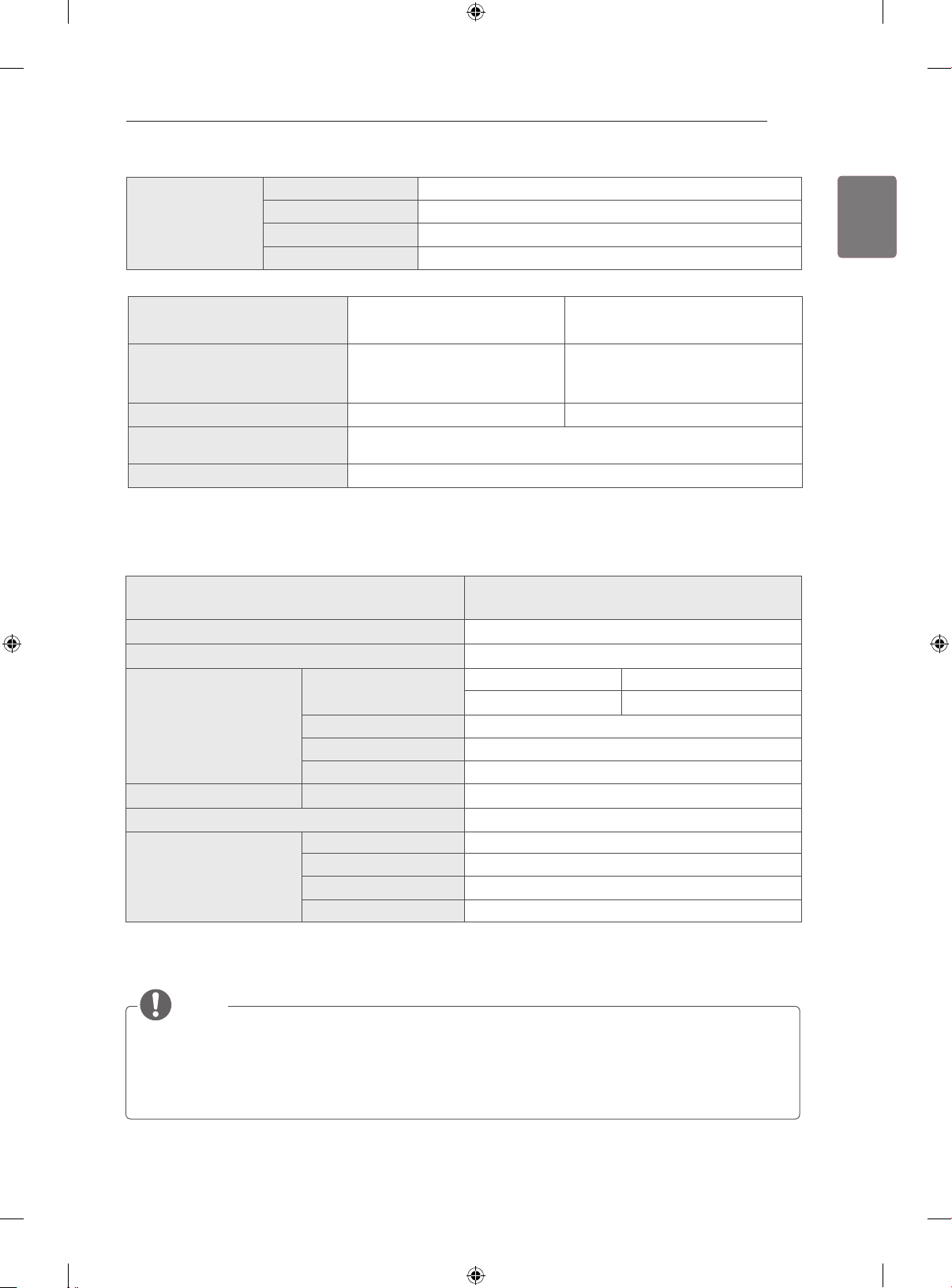
Operating Temperature 0 °C to 40 °C
Environment
condition
Television System DVB-T(*DVB-T/T2)
Programme Coverage VHF, UHF VHF, UHF, CATV
Maximum number of
storable programmes
External Antenna Impedance 75 Ω
* : Only DVB-T2 support models.
Dimensions (Width x Height x Depth) (mm)
Weight (g)
Video
Audio Microphone 2 microphones
Interface USB
Environmental conditions
Operating Humidity Less than 80 %
Storage Temperature -20 °C to 60 °C
Storage Humidity Less than 85 %
Digital TV
(Depending on Country)
DVB-T/T2 & Analogue TV : 1,500
MODEL
Lens
Effective pixels 1920 x 1080
Output format H.264, MJPEG, YUV
Output Image Full-HD, HD, VGA, QVGA, QQVGA
Operating Temperature
Operating Humidity
Storage Temperature
Storage Humidity
Focus More than 100 cm
Field of Vision 61.25° in diagonal
(Depending on Country)
PAL B/B, PAL B/G, PAL D/K, PAL-I
SECAM B/G, SECAM D/K
AN-VC500
(Video Call Camera)
112 x 56 x 38
107.8
0 °C - 40 °C
0 % - 80 %
-20 °C - 70 °C
0 % - 90 %
ENGLISH
ENG
Analogue TV
NTSC-M
The specifications shown above may be altered without prior notice to improve quality.
y
This product follows Encoding Camera Specification (SECS) 2.1.
y
NOTE
Video calls through an LG TV cannot be made using the following devices:
y
» ASUS Video Phone Touch SV1TS
» ASUS Videophone Touch SV1TW
» AIGURU_SV1 Video Phone
The list of devices that are not supported may be amended without prior notication.
y
Page 40
SPECIFICATIONS
40
ENGLISH
ENG
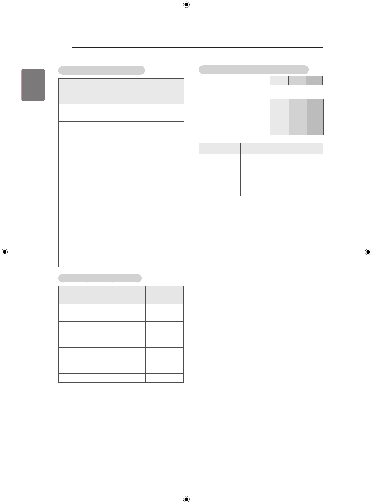
HDMI/DVI-DTV supported mode
Horizontal
Resolution
640 x 480
720 x 480
720 x 576 31.25 50
1280 x 720
1920 x 1080
Frequency
(kHz)
31.469 59.94
31.5 60
31.469 59.94
31.5 60
37.5 50
44.96 59.94
45 60
33.72 59.94
33.75 60
28.125 50
26.97 23.97
27 24
33.716 29.976
33.75 30.00
56.25 50
67.43 59.94
67.5 60
Vertical
Frequency
(Hz)
Component port connecting information
Component ports on the TV Y P
Y P
Video output ports on DVD
player
Y B-Y R-Y
Y Cb Cr
Y Pb Pr
Signal Component
480i / 576i O
480p / 576p O
720p / 1080i O
1080p
(50 Hz / 60 Hz only)
B
B
O
P
R
P
R
HDMI/DVI-PC supported mode
Resolution
640 x 350 31.468 70.09
720 x 400 31.469 70.08
640 x 480 31.469 59.94
800 x 600 37.879 60.31
1024 x 768 48.363 60.00
1152 x 864 54.348 60.053
1360 x 768 47.712 60.015
1280 x 1024 63.981 60.020
1920 x 1080 67.50 60.00
Horizontal
Frequency
(kHz)
Vertical
Frequency
(Hz)
Page 41
SPECIFICATIONS
41
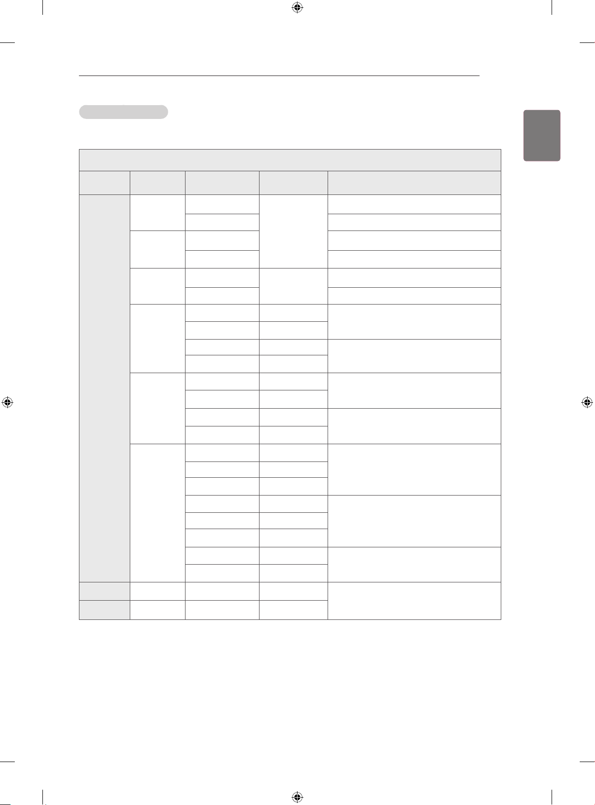
3D supported mode
y Video, which is input as below media contents is switched into the 3D screen automatically.
3D supported mode automatically
Input Signal
640 X 480
480p
576p
720p
HDMI
1080i
Horizontal
Frequency (kHz)
31.469 / 31.5
62.938 / 63 Frame Packing, Line Alternative
31.469 / 31.5
62.938 / 63 Frame Packing, Line Alternative
31.25
62.5 Frame Packing, Line Alternative
37.50 50
44.96 / 45 59.94 / 60
75 50
89.91 / 90 59.94 / 60
28.125 50
33.72 / 33.75 59.94 / 60
56.25 50
67.432 / 67.5 59.94 / 60
Vertical
Frequency (Hz)
59.94 / 60
50
Playable 3D video format
Side by Side(Half), Side by Side(Full)
Side by Side(Half), Side by Side(Full)
Side by Side(Half), Side by Side(Full)
Side by Side(Half), Side by Side(Full)
Frame Packing, Line Alternative
Side by Side(Half), Side by Side(Full)
Frame Packing, Field Alternative
ENGLISH
ENG
Top & Bottom,
Top & Bottom,
Top & Bottom,
Top & Bottom,
Top & Bottom,
26.97 / 27 23.97 / 24
28.125 25
33.716 / 33.75 29.976 / 30
43.94 / 54 23.97 / 24
1080p
56.25 25
67.432 / 67.5 29.976 / 30
56.25 50
67.432 / 67.5 59.94 / 60
USB 1080p 33.75 30
DLNA 1080p 33.75 30
Side by Side(Half), Side by Side(Full)
Top & Bottom,
Frame Packing, Line Alternative
Top & Bottom, Side by Side(Half)
Side by Side(Half), Top & Bottom,
Checker Board, MPO(Photo), JPS(Photo)
Page 42
SPECIFICATIONS
42
ENGLISH
ENG
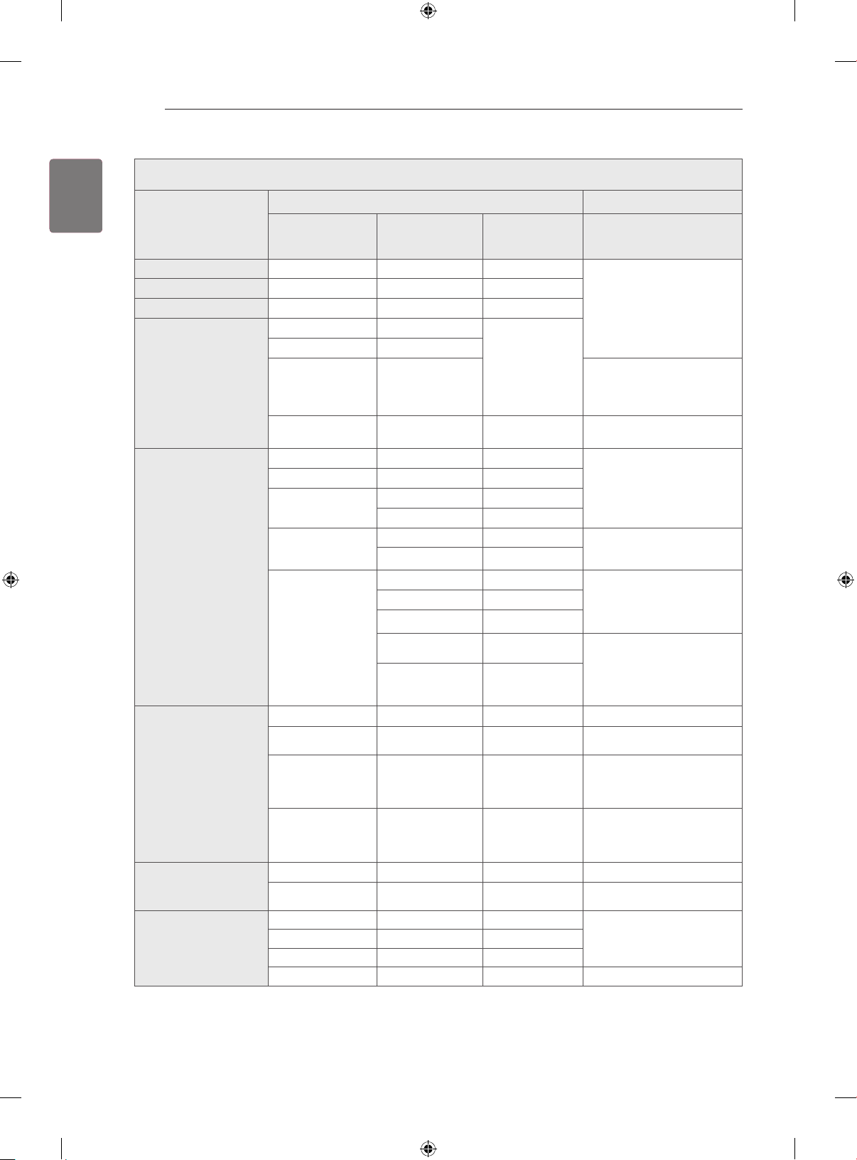
3D supported mode manually
Signal
Input
DTV HD / SD - -
ATV(CVBS) SD - -
Component HD / SD - -
HDMI-PC
HDMI-DTV
Resolution
1024 x 768 48.36
1360 x 768 47.71
1920 x 1080 67.5
Others - -
480p 31.5 60
576p 31.25 50
720p
1080i
1080p
Horizontal
Frequency
(kHz)
37.5 50
45 60
28.12 50
33.75 60
27 24
28.12 25
33.75 30
56.25 50
67.5 60
Frequency (Hz)
Vertical
60
Playable 3D video format
2D to 3D, Side by Side(Half),
Top & Bottom
2D to 3D, Side by Side(Half),
Top & Bottom, Checker Board,
Frame Sequential, Row Inter-
leaving, Column Interleaving
2D to 3D, Side by Side(Half),
Top & Bottom
2D to 3D, Side by Side(Half),
Top & Bottom, Checker Board,
Frame Sequential, Row Inter-
leaving, Column Interleaving
2D to 3D, Side by Side(Half),
Top & Bottom
2D to 3D, Side by Side(Half),
Top & Bottom, Checker Board,
Row Interleaving, Column
Interleaving
2D to 3D, Side by Side(Half),
Top & Bottom, Checker Board,
Frame Sequential, Row Inter-
leaving, Column Interleaving
USB, DLNA
(Movie)
USB, DLNA
(Photo)
Miracast/Widi
Under 704 x 480 - -
Over 704 x 480
interlaced
Over 704 x 480
progressive
Over 704 x 480
progressive
Under 320 x 240 - -
Over 320 x 240 - -
1024 x 768p - 30 / 60
1280 x 720p - 30 / 60
1920 x 1080p - 30 / 60
Others - -
- -
- 50 / 60
- Others
2D to 3D
2D to 3D, Side by Side(Half),
Top & Bottom
2D to 3D, Side by Side(Half),
Top & Bottom, Checker Board,
Frame Sequential, Row Inter-
leaving, Column Interleaving
2D to 3D, Side by Side(Half),
Top & Bottom, Checker Board,
Row Interleaving, Column
Interleaving
2D to 3D
2D to 3D, Side by Side(Half),
Top & Bottom
2D to 3D, Side by Side(Half),
Top & Bottom
2D to 3D
Page 43
LICENSES / OPEN SOURCE SOFTWARE NOTICE / EXTERNAL CONTROL DEVICE SETUP
43
LICENSES
Supported licenses may differ by model. For more information about licenses, visit www.lg.com.
Manufactured under license from Dolby Laboratories. Dolby and the double-D symbol are trademarks of Dolby Laboratories.
The terms HDMI and HDMI High-Denition Multimedia Interface, and the HDMI logo are trademarks or registered trademarks of HDMI Licensing LLC in the United States and other countries.
ABOUT DIVX VIDEO: DivX® is a digital video format created by DivX, LLC, a subsidiary of Rovi
Corporation. This is an ofcial DivX Certied® device that has passed rigorous testing to verify
that it plays DivX video. Visit divx.com for more information and software tools to convert your
les into DivX video.
ABOUT DIVX VIDEO-ON-DEMAND: This DivX Certied® device must be registered in order to
play purchased DivX Video-on-Demand (VOD) movies. To obtain your registration code, locate
the DivX VOD section in your device setup menu. Go to vod.divx.com for more information on
how to complete your registration.
“DivX Certied® to play DivX® video up to HD 1080p, including premium content.”
“DivX®, DivX Certied® and associated logos are trademarks of Rovi Corporation or its subsidiaries and are used under license.”
“Covered by one or more of the following U.S. patents :
7,295,673; 7,460,668; 7,515,710; 7,519,274”
ENGLISH
ENG
For DTS patents, see http://patents.dts.com. Manufactured under license from DTS Licensing
Limited. DTS, the Symbol, & DTS and the Symbol together are registered trademarks, and DTS
2.0+Digital Out is a trademark of DTS, Inc. © DTS, Inc. All Rights Reserved.
OPEN SOURCE SOFTWARE NOTICE
To obtain the source code under GPL, LGPL, MPL and other open source licenses, that is contained in this product,
please visit http://opensource.lge.com.
In addition to the source code, all referred license terms, warranty disclaimers and copyright notices are available for
download.
LG Electronics will also provide open source code to you on CD-ROM for a charge covering the cost of performing such
distribution (such as the cost of media, shipping and handling) upon email request to [email protected]. This offer is
valid for three (3) years from the date on which you purchased the product.
EXTERNAL CONTROL DEVICE SETUP
To obtain the external control device setup information, please visit www.lg.com.
Page 44
Record the model number and serial number of
the TV.
Refer to the label on the back cover and quote
this information to your dealer when requiring
any service.
MODEL
SERIAL
(Only DTV)
Page 45

OWNER’S MANUAL
EXTERNAL CONTROL
DEVICE SETUP
Please read this manual carefully before operating the set and retain it for
future reference.
www.lg.com
Page 46
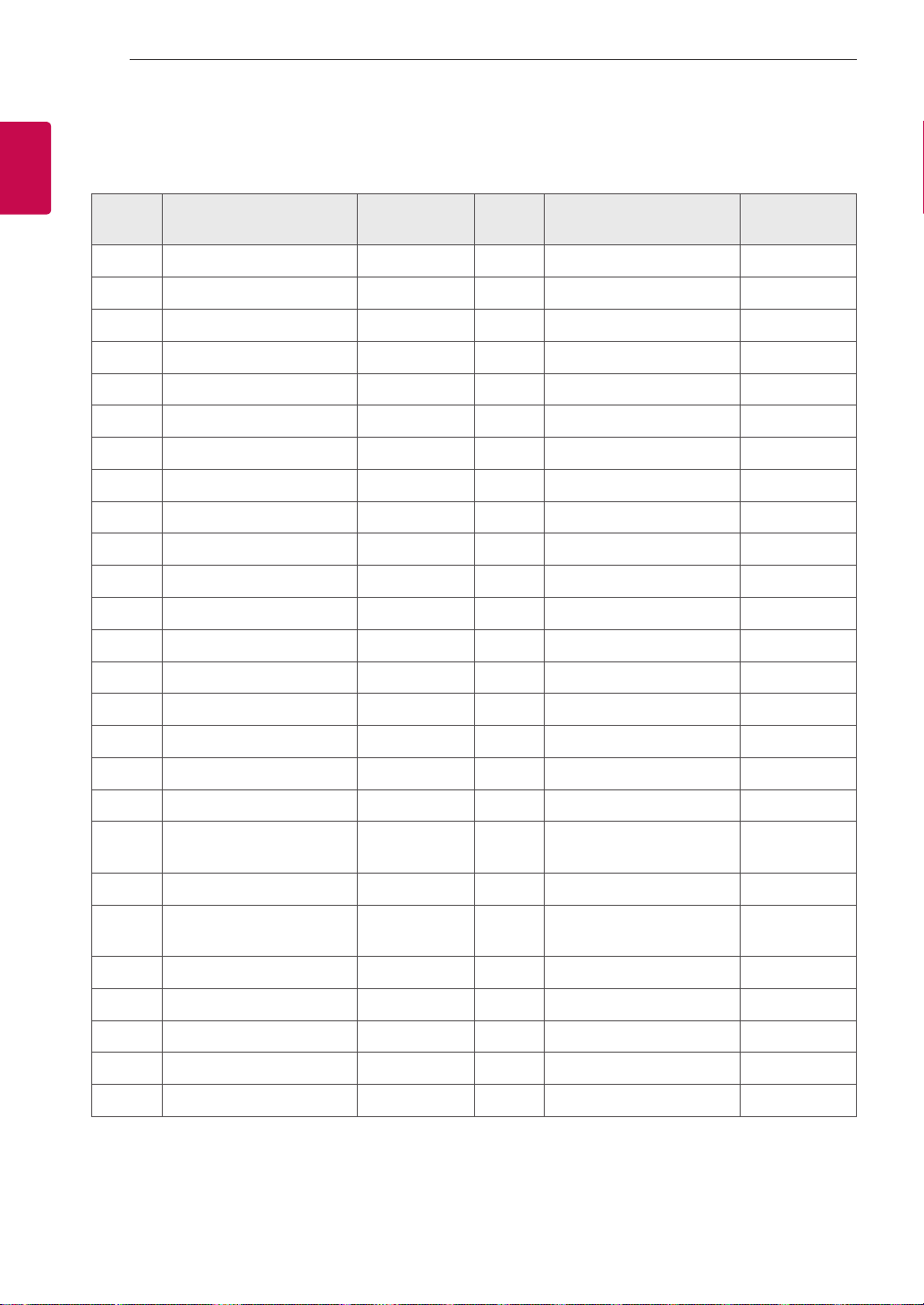
KEY CODES
2
2
ENGLISH
ENG
KEY CODES
• This feature is not available for all models.
Code
(Hexa)
00 CH +, PR + R/C Button 53 List R/C Button
01 CH -, PR - R/C Button 5B Exit R/C Button
02 Volume + R/C Button 60 PIP(AD) R/C Button
03 Volume - R/C Button 61 Blue R/C Button
06 > (Arrow Key / Right Key) R/C Button 63 Yellow R/C Button
07 < (Arrow Key / Left Key) R/C Button 71 Green R/C Button
08 Power R/C Button 72 Red R/C Button
09 Mute R/C Button 79 Ratio / Aspect Ratio R/C Button
0B Input R/C Button 91 AD (Audio Description) R/C Button
0E SLEEP R/C Button 7A User Guide R/C Button
0F TV, TV/RAD R/C Button 7C Smart / Home R/C Button
10 - 19 * Number Key 0 - 9 R/C Button 7E SIMPLINK R/C Button
1A Q.View / Flashback R/C Button 8E ►►(Forward) R/C Button
Function Note
Code
(Hexa)
Function Note
1E FAV (Favorite Channel) R/C Button 8F ◄◄(Rewind) R/C Button
20 Text (Teletext) R/C Button AA Info R/C Button
21 T. Opt (Teletext Option) R/C Button AB Program Guide R/C Button
28 Return (BACK) R/C Button B0 ►(Play) R/C Button
30 AV (Audio / Video) Mode R/C Button B1 ꕗ (Stop / File List) R/C Button
39 Caption/Subtitle R/C Button BA
40 Λ
41
42 My Apps R/C Button DC 3D R/C Button
43 Menu / Settings R/C Button 99 AutoConfig R/C Button
44 OK / Enter R/C Button 9F App / * R/C Button
45 Q.Menu R/C Button
4C List, - (ATSC Only) R/C Button
* Key code 4C (0x4C) is available on ATSC/ISDB models which use major/minor channel.
(For South Korea, Japan, North America, Latin America except Colombia models)
(Arrow Key / Cursor Up)
V (Arrow Key / Cursor
Down)
R/C Button BB Soccer R/C Button
R/C Button BD ꔄ (REC) R/C Button
ꕘ (Freeze / Slow Play /
Pause)
R/C Button
Page 47
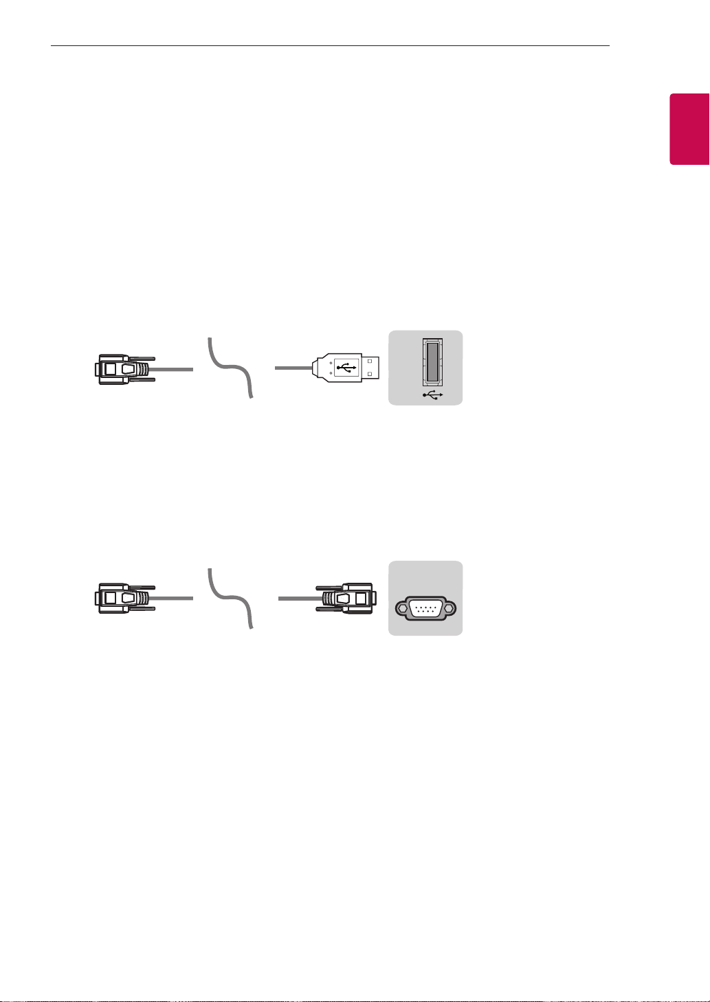
EXTERNAL CONTROL DEVICE SETUP
USB IN
(TV)
(PC)
3
3
EXTERNAL CONTROL DEVICE SETUP
• Image shown may differ from your TV.
Connect the USB to Serial converter/RS-232C input jack to an external control device (such as a computer
or an A/V control system) to control the product’s functions externally.
Note: The type of control port on the TV can be different between model series.
* Please be advised that not all models support this type of connectivity.
* Cable is not provided.
USB to Serial converter with USB Cable
USB Type
(PC)
• LGTV supports PL2303 chip-based (Vendor ID : 0x0557, Product ID : 0x2008) USB to serial converter
which is not made nor provided by LG.
• It can be purchased from computer stores that carry accessories for IT support professionals.
USB IN
RS-232C With RS232C Cable
DE9 (D-Sub 9pin) Type
• You need to purchase the RS-232C (DE9, D-Sub 9pin female-to-female type) to RS-232C cable required
for the connection between the PC and the TV, which is specified in the manual.
(TV)
ENGENGLISH
(PC)
The connection interface may differ from your TV.
(CONTROL & SERVICE)
RS-232C IN
(TV)
Page 48
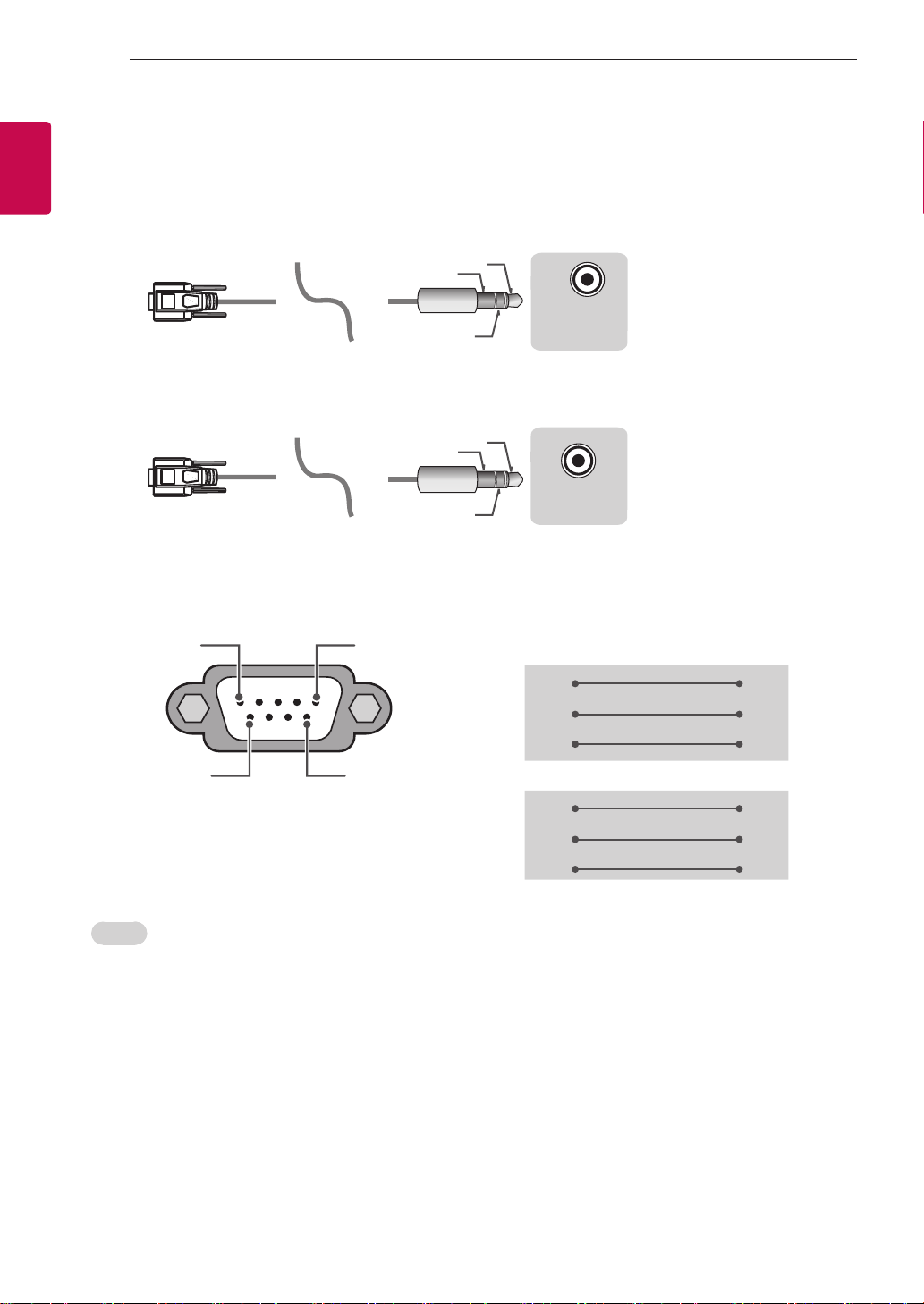
EXTERNAL CONTROL DEVICE SETUP
USB IN
(TV)
(PC)
(PC)
RS-232C IN
(CONTROL & SERVICE)
(TV)
USB IN
(TV)
(PC)
(PC)
RS-232C IN
(CONTROL & SERVICE)
(TV)
(TV)
(PC)
(PC
SERVICE ONLY
1
3
2
4
4
ENGLISH
ENG
Phone jack Type
• You need to purchase the phone-jack to RS-232 cable required for the connection between the PC and
the TV, which is specified in the manual.
* For other models, connect to the USB port.
* The connection interface may differ from your TV.
1
3
(PC)
- or
2
1
3
SERVICE ONLY
)
RS-232C IN
2
(CONTROL & SERVICE)
(TV)
(TV)
Customer Computer RS-232C configurations
3-Wire Configurations(Not standard)
1
6
RS-232C
(Serial port)
Set ID
For Set ID number, see "Real Data Mapping" on p.6
5
RXD 2 2 TXD
TXD 3 1 RXD
GND 5 3 GND
9
RXD 3 2 TXD
TXD 2 1 RXD
GND 5 3 GND
PC TV
OR
D-Sub 9 Phone
1. Press SETTINGS to access the main menus.
2. Press the Navigation buttons to scroll to (*General → About this TV or OPTION) and press OK.
3. Press the Navigation buttons to scroll to SET ID and press OK.
4. Scroll left or right to select a set ID number and select CLOSE. The adjustment range is 1-99.
5. When you are finished, press EXIT.
* (Depending on model)
Page 49
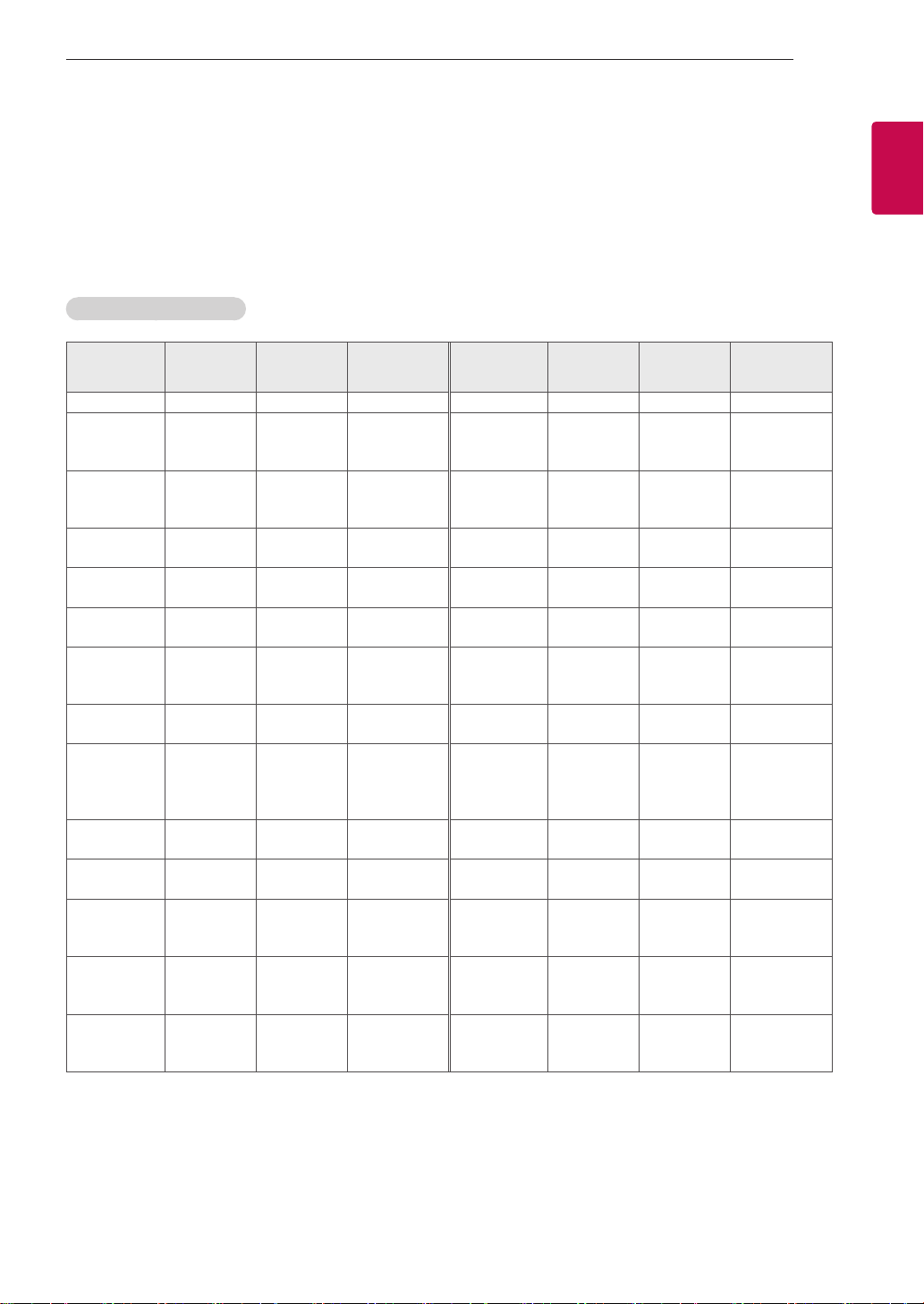
EXTERNAL CONTROL DEVICE SETUP
5
5
Communication Parameters
• Baud rate : 9600 bps (UART)
• Data length : 8 bits
• Parity : None
• Stop bit : 1 bit
• Communication code : ASCII code
• Use a crossed (reverse) cable.
Command reference list
(Depending on model)
COMMAND1 COMMAND2
01. Power* k a 00 to 01 15. Balance k t 00 to 64
02. Aspect
Ratio
03. Screen
Mute
04. Volume
Mute
05. Volume
Control
06. Contrast k g 00 to 64
07.
Brightness
08. Color/
Colour
09. Tint k j 00 to 64
10.
Sharpness
11. OSD
Select
12. Remote
Control Lock
Mode
13. Treble k r 00 to 64
k c (p.7)
k d (p.7)
k e 00 to 01 18. Equalizer j v (p.8)
k f 00 to 64
k h 00 to 64
k i 00 to 64 22. Key m c Key Codes
k k 00 to 32
k l 00 to 01
k m 00 to 01
DATA
(Hexadecimal)
16. Color
(Colour)
Temperature
17. ISM
Method (Only
Plasma TV)
19. Energy
Saving
20. Tune
Command
21. Channel
(Programme)
Add/Del(Skip)
23. Control
Backlight,
Control Panel
Light
24. Input
select (Main)
25. 3D (Only
3D models)
26. Extended
3D (Only 3D
models)
27. Auto
Configure
COMMAND1 COMMAND2
x u 00 to 64
j p (p.8)
j q 00 to 05
m a (p.9)
m b 00 to 01
m g 00 to 64
x b (p.11)
x t (p.11)
x v (p.11)
j u (p.12)
DATA
(Hexadecimal)
ENGENGLISH
14. Bass k s 00 to 64
* Note: During playing or recording media, all commands except Power (ka) and Key (mc) are not
executed and treated as NG.
With RS232C cable, TV can communicate "ka command" in power-on or power-off status. but with
USB-to-Serial converter cable, the command works only if TV is on.
Page 50

EXTERNAL CONTROL DEVICE SETUP
6
6
ENGLISH
ENG
Transmission / Receiving Protocol
Transmission
[Command1][Command2][ ][Set ID][ ][Data][Cr]
[Command 1] : First command to control the TV. (j, k, m or x)
[Command 2] : Second command to control the TV.
[Set ID] : You can adjust the [Set ID] to choose desired monitor ID number in option menu.
Adjustment range in TV is 1 to 99. If [Set ID] value is selected to ‘0’, every connected set
can be controlled.
* [Set ID] is indicated as decimal (1 to 99) on menu and as Hexadecimal (0x00 to 0x63) on
transmission/receiving protocol.
[DATA] : To transmit command data (hexadecimal). Transmit ‘FF’ data to read status of command.
[Cr] : Carriage Return - ASCII code ‘0x0D’
[ ] : Space – ASCII code ‘0x20’
OK Acknowledgement
[Command2][ ][Set ID][ ][OK][Data][x]
* The set transmits ACK (acknowledgement) based on this format when receiving normal data. At this time,
if the data is data read mode, it indicates present status data. If the data is data write mode, it returns the
data of the PC computer.
Error Acknowledgement
[Command2][ ][Set ID][ ][NG][Data][x]
* The set transmits ACK (acknowledgement) based on this format when receiving abnormal data from
non-viable functions or communication errors.
Data 00: Illegal Code
Real data mapping (Hexadecimal b Decimal)
* When you enter the [data] in hexadecimal, refer to following conversion table.
* Channel Tune (ma) Command uses two-byte hexadecimal value([data]) to select channel number.
00 : Step 0 32 : Step 50 (Set ID 50) FE : Step 254
01 : Step 1 (Set ID 1) 33 : Step 51 (Set ID 51) FF : Step 255
... ... ...
0A : Step 10 (Set ID 10) 63 : Step 99 (Set ID 99) 01 00 : Step 256
... ... ...
0F : Step 15 (Set ID 15) C7 : Step 199 27 0E : Step 9998
10 : Step 16 (Set ID 16) C8 : Step 200 27 0F : Step 9999
... ... ...
Page 51

EXTERNAL CONTROL DEVICE SETUP
* Commands may work differently depending on model and signal.
01. Power (Command: k a)
► To control Power *On or Off of the set.
Transmission[k][a][ ][Set ID][ ][Data][Cr]
Data 00 : Power Off 01 : *Power On
Ack [d][ ][Set ID][ ][OK/NG][Data][x]
* In case of video mute on only, TV will display On
Screen Display(OSD). But, in case of Screen mute
on, TV will not display OSD.
7
7
ENGENGLISH
Ack [a][ ][Set ID][ ][OK/NG][Data][x]
► To Show TV is Power On or *Off
Transmission [k][a][ ][Set ID][ ][FF][Cr]
Ack [a][ ][Set ID][ ][OK][Data][x]
* Similarly, if other functions transmit ‘FF’ data
based on this format, Acknowledgement feedback
presents status about each function.
02. Aspect Ratio (Command: k c)
(Main Picture Size)
► To adjust the screen format. (Main picture format)
You can also adjust the screen format using the
Aspect Ratio in the Q.MENU. or PICTURE menu.
Transmission [k][c][ ][Set ID][ ][Data][Cr]
Data 01 : Normal screen
(4:3)
02 : Wide screen
(16:9)
04 : Zoom
05 : Zoom 2
(Latin America
except Colombia
Only)
06 : Set by Program/
Original
Ack [c][ ][Set ID][ ][OK/NG][Data][x]
07 : 14:9
(Europe, Colombia, Mid-East,
Asia except South Korea and
Japan)
09 : * Just Scan
0B : Full Wide
(Europe, Colombia, MidEast, Asia except South
Korea and Japan)
10 to 1F : Cinema Zoom 1
to 16
* Using the PC input, you select either 16:9 or 4:3
screen aspect ratio.
* In DTV/HDMI/Component mode (high-definition),
Just Scan is available.
* Full wide mode may work differently based on
model and is supported for DTV fully, and ATV,
AV partially.
04. Volume Mute (Command: k e)
► To control volume mute on/off.
You can also adjust mute using the MUTE button
on remote control.
Transmission [k][e][ ][Set ID][ ][Data][Cr]
Data 00 : Volume mute on (Volume off)
01 : Volume mute off (Volume on)
Ack [e][ ][Set ID][ ][OK/NG][Data][x]
05. Volume Control (Command: k f)
► To adjust volume.
You can also adjust volume with the volume
buttons on remote control.
Transmission [k][f][ ][Set ID][ ][Data][Cr]
Data Min : 00 to Max : 64
Ack [f][ ][Set ID][ ][OK/NG][Data][x]
06. Contrast (Command: k g)
► To adjust screen contrast.
You can also adjust contrast in the PICTURE
menu.
Transmission [k][g][ ][Set ID][ ][Data][Cr]
Data Min : 00 to Max : 64
Ack [g][ ][Set ID][ ][OK/NG][Data][x]
07. Brightness (Command: k h)
► To adjust screen brightness.
You can also adjust brightness in the PICTURE
menu.
Transmission [k][h][ ][Set ID][ ][Data][Cr]
03. Screen Mute (Command: k d)
► To select screen mute on/off.
Transmission [k][d][ ][Set ID][ ][Data][Cr]
Data 00 : Screen mute off (Picture on)
Video mute off
01 : Screen mute on (Picture off)
10 : Video mute on
Data Min : 00 to Max : 64
Ack [h][ ][Set ID][ ][OK/NG][Data][x]
08. Color/Colour (Command: k i)
► To adjust the screen Color(Colour).
You can also adjust colour in the PICTURE menu.
Transmission [k][i][ ][Set ID][ ][Data][Cr]
Page 52
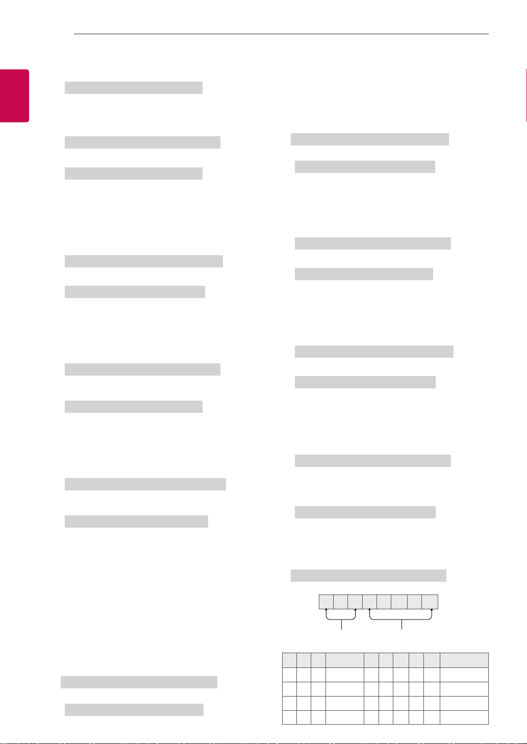
EXTERNAL CONTROL DEVICE SETUP
8
8
ENGLISH
ENG
Data Min : 00 to Max : 64
Ack [i][ ][Set ID][ ][OK/NG][Data][x]
09. Tint (Command: k j)
► To adjust the screen tint.
You can also adjust tint in the PICTURE menu.
Transmission [k][j][ ][Set ID][ ][Data][Cr]
Data Red : 00 to Green : 64
Ack [j][ ][Set ID][ ][OK/NG][Data][x]
10. Sharpness (Command: k k)
► To adjust the screen sharpness.
You can also adjust sharpness in the PICTURE
menu.
Transmission [k][k][ ][Set ID][ ][Data][Cr]
Data Min : 00 to Max : 32
Ack [k][ ][Set ID][ ][OK/NG][Data][x]
11. OSD Select (Command: k l)
► To select OSD (On Screen Display) on/off when
controlling remotely.
Transmission [k][l][ ][Set ID][ ][Data][Cr]
Data 00 : OSD off 01 : OSD on
* (Depending on model)
14. Bass (Command: k s)
► To adjust Bass.
You can also adjust in the AUDIO menu.
Transmission [k][s][ ][Set ID][ ][Data][Cr]
Data Min : 00 to Max : 64
Ack [s][ ][Set ID][ ][OK/NG][Data][x]
* (Depending on model)
15. Balance (Command: k t)
► To adjust balance.
You can also adjust balance in the AUDIO menu.
Transmission [k][t][ ][Set ID][ ][Data][Cr]
Data Min : 00 to Max : 64
Ack [t][ ][Set ID][ ][OK/NG][Data][x]
16. Color(Colour) Temperature (Command: x u)
► To adjust colour temperature. You can also adjust
Color(Colour) Temperature in the PICTURE menu.
Transmission [x][u][ ][Set ID][ ][Data][Cr]
Data Min : 00 to Max : 64
Ack [u][ ][Set ID][ ][OK/NG][Data][x]
Ack [l][ ][Set ID][ ][OK/NG][Data][x]
12. Remote control lock mode (Command: k m)
► To lock the front panel controls on the monitor and
remote control.
Transmission [k][m][ ][Set ID][ ][Data][Cr]
Data 00 : Lock off 01 : Lock on
Ack [m][ ][Set ID][ ][OK/NG][Data][x]
* If you are not using the remote control, use this
mode.
When main power is off & on (plug-off and plug-in,
after 20 - 30 seconds), external control lock is
released.
* In the standby mode (DC off by off timer or ‘ka’,
‘mc’ command), and if key lock is on, TV will not
turn on by power on key of IR & Local Key.
13. Treble (Command: k r)
► To adjust treble.
You can also adjust in the AUDIO menu.
Transmission [k][r][ ][Set ID][ ][Data][Cr]
Data Min : 00 to Max : 64
Ack [r][ ][Set ID][ ][OK/NG][Data][x]
17. ISM Method (Command: j p) (Only Plasma TV)
► To control the ISM method. You can also adjust
ISM Method in OPTION menu.
Transmission [j][p][ ][Set ID][ ][Data][Cr]
Data Min : 02: Orbiter
08: Normal
20: Color(Colour) Wash
Ack [p][ ][Set ID][ ][OK/NG][Data][x]
18. Equalizer (Command : j v)
► Adjust EQ of the set.
Transmission [j][v][ ][Set ID][ ][Data][Cr]
MSB
0 0 0 0 0 0 0 0
LSB
Frequency Data
7 6 5
0 0 0
0 0 1
0 1 0
0 1 1
Frequency
1st Band
2nd Band
3rd Band
4th Band
4 3 2 1 0 Step
0 0 0 0 0
0 0 0 0 1
... ... ... ... ...
0 0 0 1 1
0(decimal)
1(decimal)
...
19(decimal)
Page 53

EXTERNAL CONTROL DEVICE SETUP
9
9
1 0 0
Acknowledgement [v][ ][Set ID][ ][OK/NG][Data][x]
* It depends on model, and can adjust when sound
mode is EQ adjustable value.
5th Band
0 0 1 0 1
20(decimal)
19. Energy Saving (Command: j q)
► To reduce the power consumption of the TV. You
can also adjust Energy Saving in PICTURE menu.
Transmission [j][q][ ][Set ID][ ][Data][Cr]
Data
00 : Off
01 : Minimum
02 : Medium
03 : Maximum
04 : Auto (For LCD TV / LED TV) /
Intelligent sensor (For PDP TV)
05 : Screen off
* (Depending on model)
Ack [q][ ][Set ID][ ][OK/NG][Data][x]
20. Tune Command (Command: m a)
* This command may work differently depending on
model and signal.
• For Europe, Mid-East, Colombia, Asia except
South Korea and Japan Model
► Select channel to following physical number.
Transmission [m][a][ ][Set ID][ ][Data 00][ ]
[Data 01][ ][Data 02][Cr]
* Analog Antenna/Cable
[Data 00][Data 01] Channel Data
Data 00 : High byte channel data
Data 01 : Low byte channel data
- 00 00 ~ 00 C7 (Decimal : 0 ~ 199)
Data 02 : Input Source (Analog)
- 00 : Antenna TV (ATV)
- 80 : Cable TV (CATV)
* Digital Antenna/Cable/Satellite
[Data 00][Data 01]: Channel Data
Data 00 : High Channel data
Data 01 : Low Channel data
- 00 00 ~ 27 0F (Decimal: 0 ~ 9999)
Data 02 : Input Source (Digital)
- 10 : Antenna TV (DTV)
- 20 : Antenna Radio (Radio)
- 40 : Satellite TV (SDTV)
- 50 : Satellite Radio (S-Radio)
- 90 : Cable TV (CADTV)
- a0 : Cable Radio (CA-Radio)
* Tune Command Examples:
1. Tune to the Analog antenna (PAL) Channel 10.
Set ID = All = 00
Data 00 & 01 = Channel Data is 10 = 00 0a
Data 02 = Analog Antenna TV = 00
Result = ma 00 00 0a 00
2. Tune to the digital antenna (DVB-T) Channel 01.
Set ID = All = 00
Data 00 & 01 = Channel Data is 1 = 00 01
Data 02 = Digital Antenna TV = 10
Result = ma 00 00 01 10
3. Tune to the satellite (DVB-S) Channel 1000.
Set ID = All = 00
Data 00 & 01 = Channel Data is 1000 = 03 E8
Data 02 = Digital Satellite TV = 40
Result = ma 00 03 E8 40
Ack [a][ ][Set ID][ ][OK][Data 00][Data 01]
[Data 02][x][a][ ][Set ID][ ][NG][Data 00][x]
• For South Korea, North/Latin America except
Colombia Model
► To tune channel to following physical/major/minor
number.
Transmission [m][a][ ][0][ ][Data00][ ][Data01]
[ ][Data02][ ][Data03][ ][Data04][ ][Data05][Cr]
Digital channels have a Physical, Major, and Minor
channel number. The Physical number is the actual
digital channel number, the Major is the number that
the channel should be mapped to, and the Minor is
the sub-channel. Since the ATSC tuner automatically
maps the channel from the Major / Minor number,
the Physical number is not required when sending a
command in Digital.
* Analog Antenna/Cable
Data 00 : Physical Channel Number
- Antenna (ATV) : 02~45 (Decimal: 2 ~ 69)
- Cable (CATV) : 01, 0E~7D (Decimal : 1, 14~125)
[Data 01 ~ 04]: Major/Minor Channel Number
Data 01 & 02: xx (Don't care)
Data 03 & 04: xx (Don't care)
Data 05: Input Source (Analog)
- 00 : Antenna TV (ATV)
- 01 : Cable TV (CATV)
* Digital Antenna/Cable
Data 00 : xx (Don't care)
[Data 01][Data 02]: Major Channel Number
Data 01 : High byte Channel Data
Data 02 : Low byte Channel Data
- 00 01 ~ 27 0F (Decimal: 1 ~ 9999)
[Data 03][Data 04]: Minor Channel Number
Data 03 : High byte Channel Data
Data 04 : Low byte Channel Data
Data 05 : Input Source (Digital)
- 02 : Antenna TV (DTV) – Use Physical Channel
Number
- 06 : Cable TV (CADTV) – Use Physical Channel
ENGENGLISH
Page 54

EXTERNAL CONTROL DEVICE SETUP
10
10
ENGLISH
ENG
Number
- 22 : Antenna TV (DTV) – Don’t Use Physical
Channel Number
- 26 : Cable TV (CADTV) - Don’t Use Physical
Channel Number
- 46 : Cable TV (CADTV) – Use Major Channel
Number Only (One Part Channel)
Two bytes are available for each major and minor
channel data, but usually the low byte is used alone
(high byte is 0).
* Tune Command Examples:
1. Tune to the Analog cable (NTSC) channel 35.
Set ID = All = 00
Data 00 = Channel Data is 35 = 23
Data 01 & 02 = No Major = 00 00
Data 03 & 04 = No Minor = 00 00
Data 05 = Analog Cable TV = 01
Total = ma 00 23 00 00 00 00 01
2. Tune to the digital antenna (ATSC) channel 30-3.
Set ID = All = 00
Data 00 = Don’t know Physical = 00
Data 01 & 02 = Major is 30 = 00 1E
Data 03 & 04 = Minor is 3 = 00 03
Data 05 = Digital Antenna TV = 22
Total = ma 00 00 00 1E 00 03 22
Ack [a][ ][Set ID][ ][OK][Data 00][Data 01]
[Data 02][Data 03][Data 04][Data 05]
[x][a][ ][Set ID][ ][NG][Data 00][x]
• For Japan Model
► To tune channel to following physical/major/minor
number.
Transmission [m][a][ ][0][ ][Data00][ ][Data01]
[ ][Data02][ ][Data03][ ][Data04][ ][Data05][Cr]
* Digital Antenna/Satellite
Data 00: xx (Don't care)
[Data 01][Data 02]: Major Channel Number
Data 01: High byte Channel Data
Data 02: Low byte Channel Data
- 00 01 ~ 27 0F (Decimal: 1 ~ 9999)
[Data 03][Data 04]: Minor/Branch Channel Number
(Don’t care in Satellite)
Data 03: High byte Channel Data
Data 04: Low byte Channel Data
Data 05 : Input Source (Digital/Satellite for Japan)
- 02 : Antenna TV (DTV)
- 07 : BS (Broadcasting Satellite)
- 08 : CS1 (Communication Satellite 1)
- 09 : CS2 (Communication Satellite 2)
* Tune Command Examples:
1
Tune to the digital antenna (ISDB-T) channel 17-1
Set ID = All = 00
Data 00 = Don’t know Physical = 00
Data 01 & 02 = Major is 17 = 00 11
Data 03 & 04 = Minor/Branch is 1 = 00 01
Data 05 = Digital Antenna TV = 02
Total = ma 00 00 00 11 00 01 02
2. Tune to the BS (ISDB-BS) channel 30.
Set ID = All = 00
Data 00 = Don’t know Physical = 00
Data 01 & 02 = Major is 30 = 00 1E
Data 03 & 04 = Don’t Care = 00 00
Data 05 = Digital BS TV = 07
Total = ma 00 00 00 1E 00 00 07
* This feature is varied based on the model.
Ack [a][ ][Set ID][ ][OK][Data 00][Data 01]
[Data 02][Data 03][Data 04][Data 05]
[x][a][ ][Set ID][ ][NG][Data 00][x]
21. Channel(Programme) Add/Del(Skip)
(Command: m b)
► To skip current channel(programme) for next time.
Transmission [m][b][ ][Set ID][ ][Data][Cr]
Data 00 : Del(ATSC,ISDB)/Skip(DVB) 01 : Add
Ack [b][ ][Set ID][ ][OK/NG][Data][x]
* Set the saved channel status to del(ATSC, ISDB)/
skip(DVB) or add.
22. Key (Command: m c)
► To send IR remote key code.
Transmission [m][c][ ][Set ID][ ][Data][Cr]
Data Key code - p.2.
Ack [c][ ][Set ID][ ][OK/NG][Data][x]
23. Control Backlight (Command: m g)
• For LCD TV / LED TV
► To control the backlight.
Transmission [m][g][ ][Set ID][ ][Data][Cr]
Data Min : 00 to Max : 64
Ack [g][ ][Set ID][ ][OK/NG][Data][x]
Control Panel Light (Command: m g)
• For Plasma TV
► To control the panel light.
Transmission [m][g][ ][Set ID][ ][Data][Cr]
Data Min : 00 to Max : 64
.
Ack [g][ ][Set ID][ ][OK/NG][Data][x]
Page 55
EXTERNAL CONTROL DEVICE SETUP
11
11
24. Input select (Command: x b)
(Main Picture Input)
► To select input source for main picture.
Transmission [x][b][ ][Set ID][ ][Data][Cr]
Data
00 : DTV
02 : Satellite DTV
ISDB-BS (Japan)
03 : ISDB-CS1 (Japan)
04 : ISDB-CS2 (Japan)
11 : CATV
20 : AV or AV1 21 : AV2
40 : Component1
60 : RGB
90 : HDMI1
92 : HDMI3
Ack [b][ ][Set ID][ ][OK/NG][Data][x]
* This function depends on model and signal.
01 : CADTV
10 : ATV
41 : Component2
91 : HDMI2
93 : HDMI4
25. 3D(Command: x t) (only 3D models)
(Depending on model)
► To change 3D mode for TV.
Transmission [x][t][ ][Set ID][ ][Data 00][ ][Data 01]
[ ][Data 02][ ][Data 03][Cr]
* (Depending on model)
Data Structure
[Data 00] 00 : 3D On
01 : 3D Off
02 : 3D to 2D
03 : 2D to 3D
[Data 01] 00 : Top and Bottom
01 : Side by Side
02 : Check Board
03 : Frame Sequential
04 : Column interleaving
05 : Row interleaving
[Data 02] 00 : Right to Left
01 : Left to Right
[Data 03] 3D Effect(3D Depth): Min : 00 - Max : 14
(*transmit by Hexadecimal code)
* [Data 02], [Data 03] functions depend on model
and signal.
* If [Data 00] is 00 (3D On), [Data 03] has no
meaning.
* If [Data 00] is 01 (3D off) or 02 (3D to 2D), [Data
01], [Data 02] and [Data 03] have no meaning.
* If [Data 00] is 03 (2D to 3D), [Data 01] and
[Data 02] have no meaning.
* If [Data 00] is 00 (3D On) or 03 (2D to 3D), [Data
03] works when 3D Mode (Genre) is manual only.
* All 3D pattern options ([Data 01]) may not be
available according to broadcasting/video signal.
[Data 00] [Data 01] [Data 02] [Data 03]
00 O O O
01 X X X
02 X X X
03 X O O
X : don’t care
Ack [t][ ][Set ID][ ][OK][Data00][Data01][Data02]
[Data03][x]
[t][ ][Set ID][ ][NG][Data00][x]
26. Extended 3D(Command: x v) (only 3D models)
(Depending on model)
► To change 3D option for TV.
Transmission [x][v][ ][Set ID][ ][Data 00][ ]
[Data 01][Cr]
[Data 00] 3D option
00 : 3D Picture Correction
01 : 3D Depth (3D Mode is Manual Only)
02 : 3D Viewpoint
06 : 3D Color Correction
07 : 3D Sound Zooming
08 : Normal Image View
09 : 3D Mode (Genre)
[Data 01] It has own range for each 3D option
determined by [Data 00].
1) When [Data 00] is 00
00 : Right to Left
01 : Left to Right
2) When [Data 00] is 01, 02
Data Min: 0 - Max: 14 (*transmit by Hexadecimal
code)
Data value range(0 - 20) converts Viewpoint range
(-10 - +10) automatically (Depending on model)
* This option works when 3D Mode (Genre) is manual
only.
3) When [Data 00] is 06, 07
00 : Off
01 : On
4) When [Data 00] is 08
00 : Revert to 3D video from 3D-to-2D
converted 2D video
01 : Change 3D video to 2D video, except
2D-to-3D video
* If conversion condition doesn’t meet, command is
treated as NG.
5) When [Data 00] is 09
00 : Standard
02 : Cinema
04 : Manual
Ack [v][ ][Set ID][ ][OK][Data00][Data01][x]
[v][ ][Set ID][ ][NG][Data00][x]
01 : Sport
03 : Extreme
05 : Auto
ENGENGLISH
Page 56

EXTERNAL CONTROL DEVICE SETUP
12
12
ENGLISH
ENG
27. Auto Configure (Command: j u)
(Depending on model)
► To adjust picture position and minimize image
shaking automatically. It works only in RGB (PC)
mode.
Transmission [j][u][ ][Set ID][ ][Data][Cr]
Data 01 : To set
Ack [u][ ][Set ID][ ][OK/NG][Data][x]
 Loading...