How it Works
Log In / Sign Up
Buy Points
How it Works
FAQ
Contact Us
Questions and Suggestions
Users
LG
Loading...
#
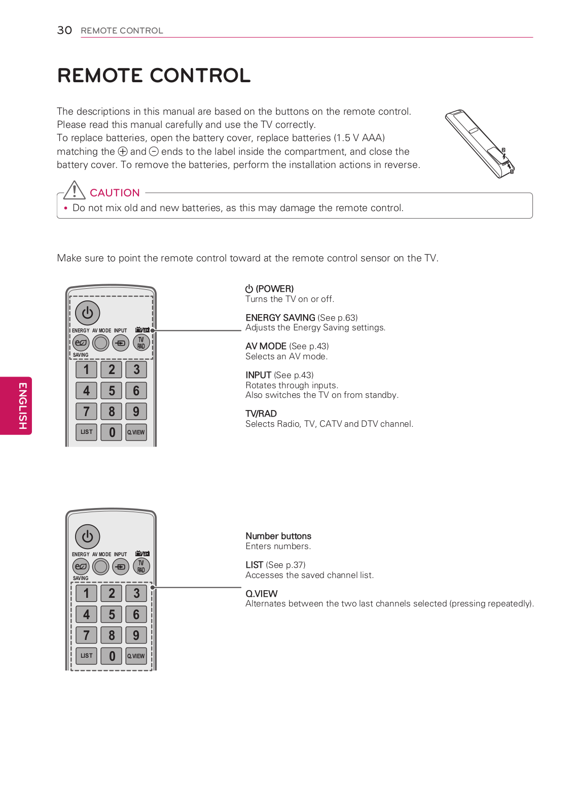
50PT350
12
50PT350C
2
50PT350R
7
50PT350R-TD
50PT350UD
50PT351
9
50PT351A
50PT351N
2
50PT351R
2
50PT352
2
50PT353
12
50PT353K
50PT353N
4
50PT45
50PT450U
50PT490
7
50PT490B
4
50PT490B-SA
50PT490B-SD
50PT490E
2
50PT490R
50PT490-TD
50PT490U
2
50PT8
39
50PT80
50PT81
10
50PT85
6
50PV25
50PV250
9
50PV250A
2
50PV250N
3
50PV250R
2
50PV35
50PV350
14
50PV350A
2
50PV350N
2
50PV350T
50PV400
4
50PV430
2
50PV450
6
50PV450C
3
50PV450UA
50PV490
50PV490UC
50PV550U
2
50PW340
2
50PW350
11
50PW350E
2
50PW350R
50PW350-TA
2
50PW350U
3
50PW350UA
50PW350-UEAUSLLHR
50PW350-UEAUSLLJR
50PW45
50PW450
9
50PW450N
50PW450T
2
50PW451
4
50PX1D
4
50PX1DH
50PX1D-UC
50PX1H
50PX2DC
50PX2DC-UD
50PX2DUD
50PX4D
4
50PX4D50
50PX4DR
4
50PX4DR-H
2
50PX4DRH-UA
50PX4DR-UA
2
50PX4D-UB
2
50PX4M
50PX4MH
2
50PX4R
27
50PX4RA
2
50PX4R-TB
50PX4R-ZB
50PX5D
8
50PX5D-UB
2
50PX5R
2
50PX5RH
50PX9
50PX950
6
50PX950-AA
50PX950N
7
50PX950UA
50PX960
50PX990
50PY2DR
8
50PY2DRH
50PY2DRH-UA
50PY2DRUA
2
50PY2R
24
50PY3D
7
50PY3DF
5
50PY3DFUA
50PY3DFUJ
50PZ200
Loading...
Loading...
Nothing found
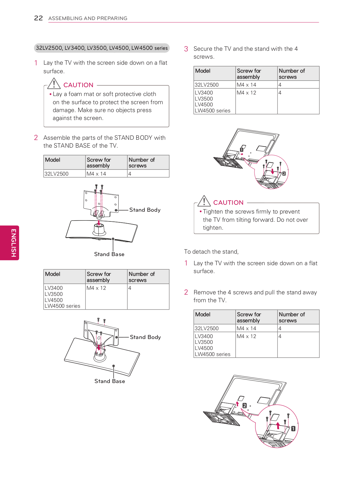
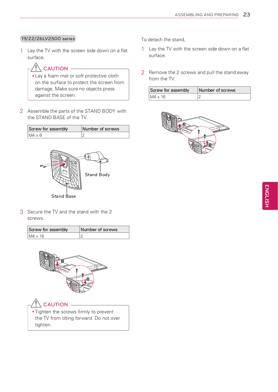
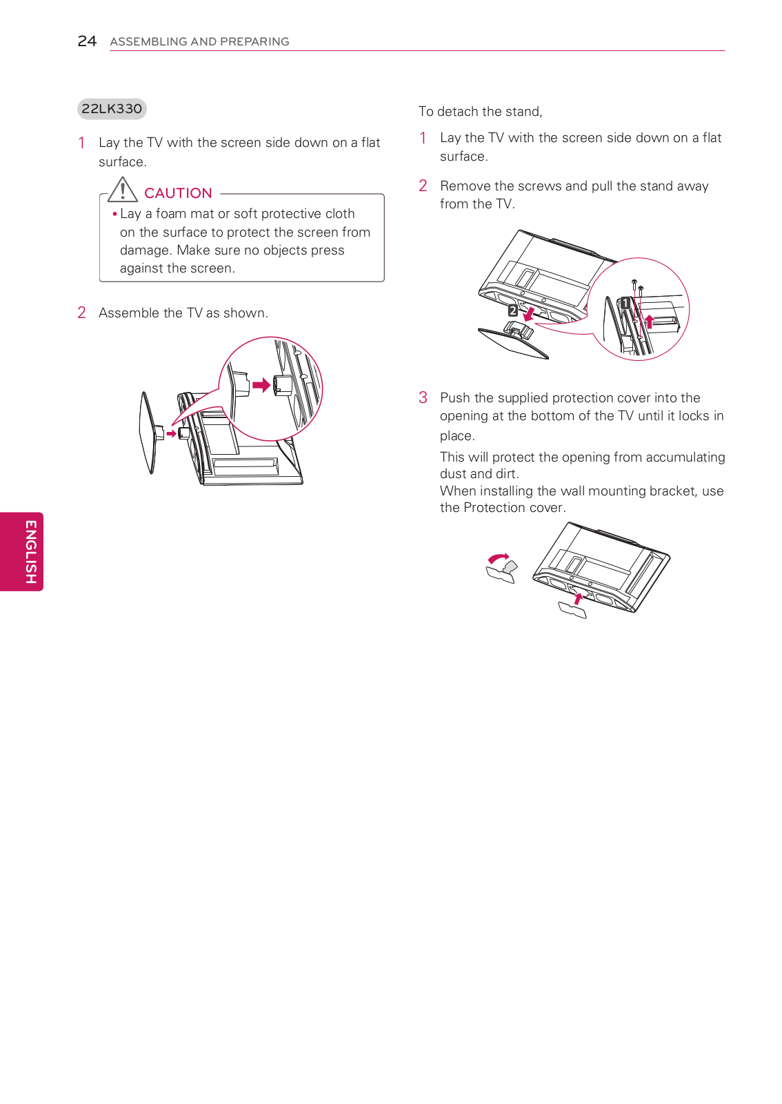
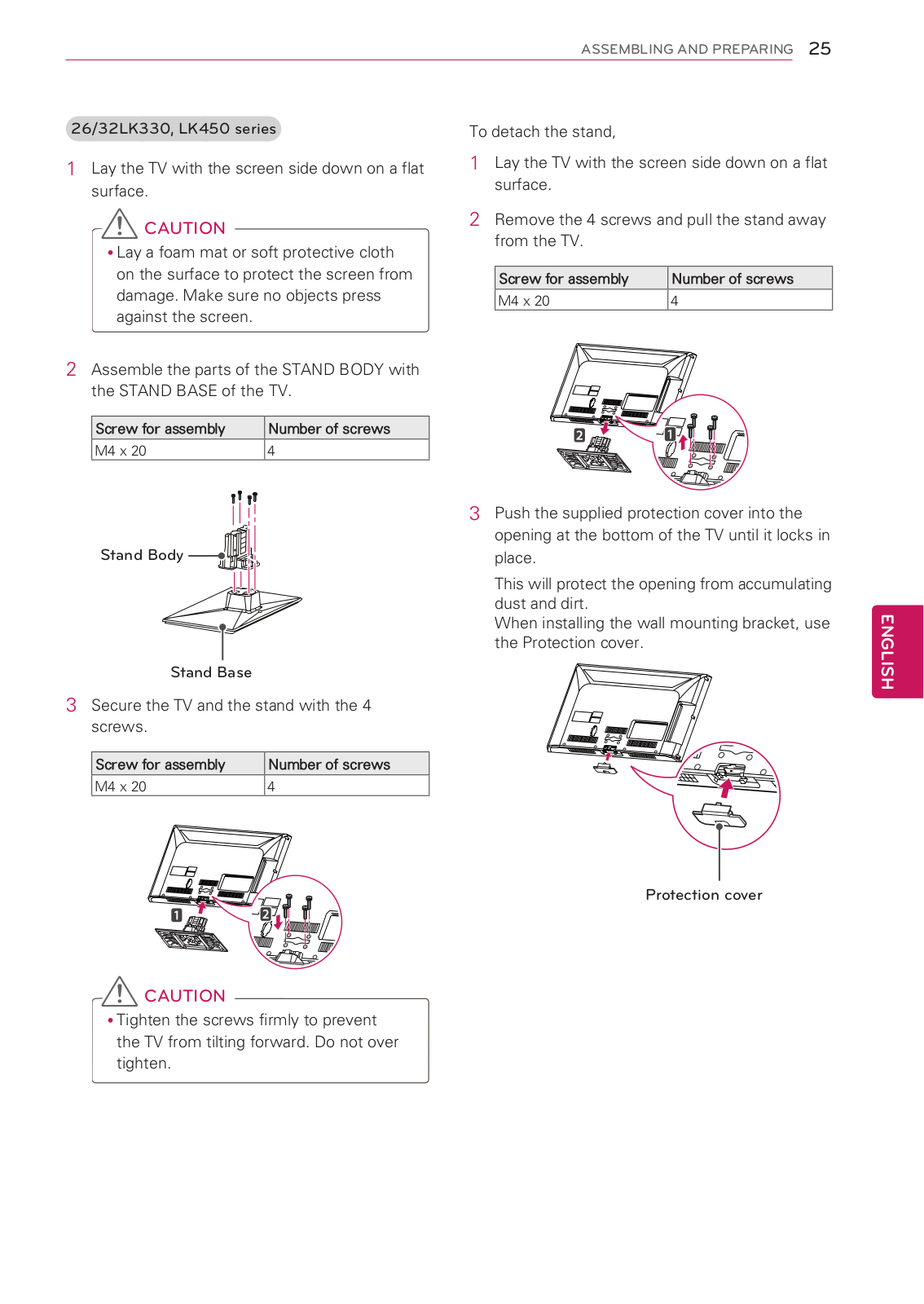
50PW350E
Owner's Manual
126 pgs
21.17 Mb
0
Owner's Manual [es]
102 pgs
21.2 Mb
0
Table of contents
Loading...
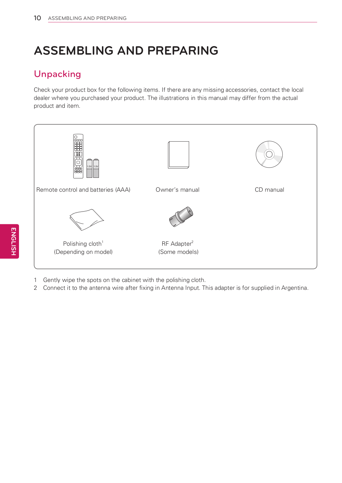
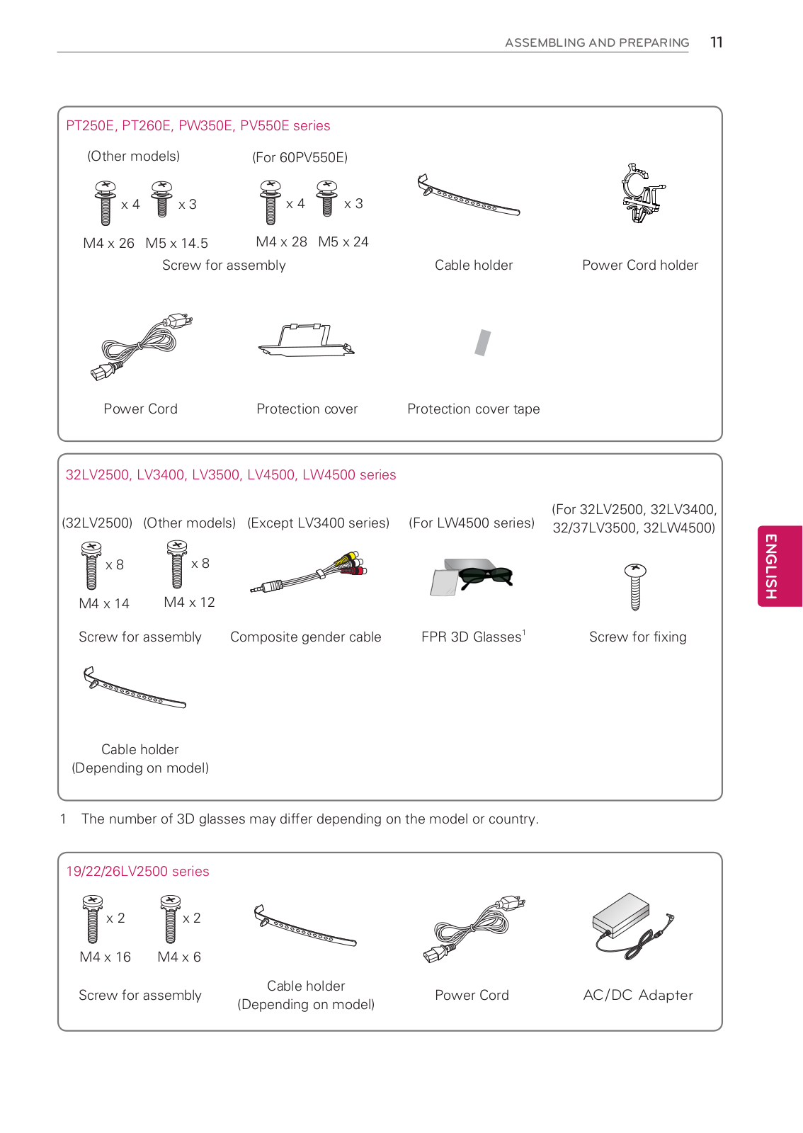
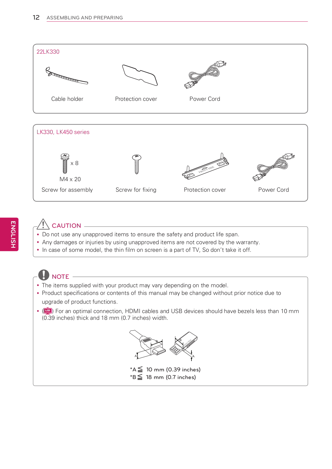
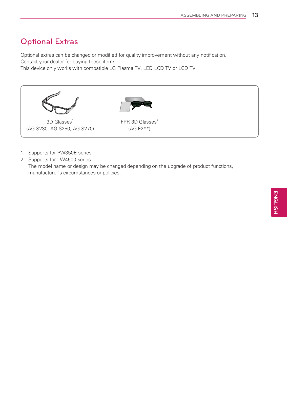
LG 37LK450, 32LK330, 32LK450, 42PT250E, 42PW350E Owner's Manual
...
LG 37LK450, 32LK330, 32LK450, 42PT250E, 42PW350E, 60PV550E, 50PT260E, 50PW350E, 50PT250E, 42LV3400, 42LW4500, 32LV3400, 32LV3500 Owner's Manual
Download
Specifications and Main Features
Frequently Asked Questions
User Manual
Download
Loading...
+
96
hidden pages
Unhide
You need points to download manuals.
1 point = 1 manual.
You can buy points or you can get point for every manual you upload.
Buy points
Upload your manuals