

Page 1

PLASMA TV
SERVICE MANUAL
CAUTION
BEFORE SERVICING THE CHASSIS,
READ THE SAFETY PRECAUTIONS IN THIS MANUAL.
CHASSIS : PP7BA
MODEL : 50PT81 50PT81-ZB
website:http://biz.LGservice.com
Internal Use Only
Page 2

- 2 -
LGE Internal Use OnlyCopyright©2007 LG Electronics. Inc. All right reserved.
Only for training and service purposes
CONTENTS
CONTENTS .............................................................................................. 2
SAFETY PRECAUTIONS ..........................................................................3
SPECIFICATION ........................................................................................4
ADJUSTMENT INSTRUCTION .................................................................7
TROUBLE SHOOTING ............................................................................17
BLOCK DIAGRAM...................................................................................28
EXPLODED VIEW .................................................................................. 30
EXPLODED VIEW PARTS LIST ............................................................ 31
REPLACEMENT PARTS LIST ............................................................... 32
SVC. SHEET ...............................................................................................
PRINTED CIRCUIT DIAGRAM ....................................................................
Page 3
- 3 -
LGE Internal Use OnlyCopyright©2007 LG Electronics. Inc. All right reserved.
Only for training and service purposes
SAFETY PRECAUTIONS
Many electrical and mechanical parts in this chassis have special safety-related characteristics. These parts are identified by in the
Schematic Diagram and Replacement Parts List.
It is essential that these special safety parts should be replaced with the same components as recommended in this manual to prevent
X-RADIATION, Shock, Fire, or other Hazards.
Do not modify the original design without permission of manufacturer.
General Guidance
An isolation Transformer should always be used during the
servicing of a receiver whose chassis is not isolated from the AC
power line. Use a transformer of adequate power rating as this
protects the technician from accidents resulting in personal injury
from electrical shocks.
It will also protect the receiver and it's components from being
damaged by accidental shorts of the circuitry that may be
inadvertently introduced during the service operation.
If any fuse (or Fusible Resistor) in this monitor is blown, replace it
with the specified.
When replacing a high wattage resistor (Oxide Metal Film Resistor,
over 1W), keep the resistor 10mm away from PCB.
Keep wires away from high voltage or high temperature parts.
Due to high vacuum and large surface area of picture tube,
extreme care should be used in handling the Picture Tube.
Do not lift the Picture tube by it's Neck.
Leakage Current Cold Check(Antenna Cold Check)
With the instrument AC plug removed from AC source, connect an
electrical jumper across the two AC plug prongs. Place the AC
switch in the on position, connect one lead of ohm-meter to the AC
plug prongs tied together and touch other ohm-meter lead in turn to
each exposed metallic parts such as antenna terminals, phone
jacks, etc.
If the exposed metallic part has a return path to the chassis, the
measured resistance should be between 1MΩ and 5.2MΩ.
When the exposed metal has no return path to the chassis the
reading must be infinite.
An other abnormality exists that must be corrected before the
receiver is returned to the customer.
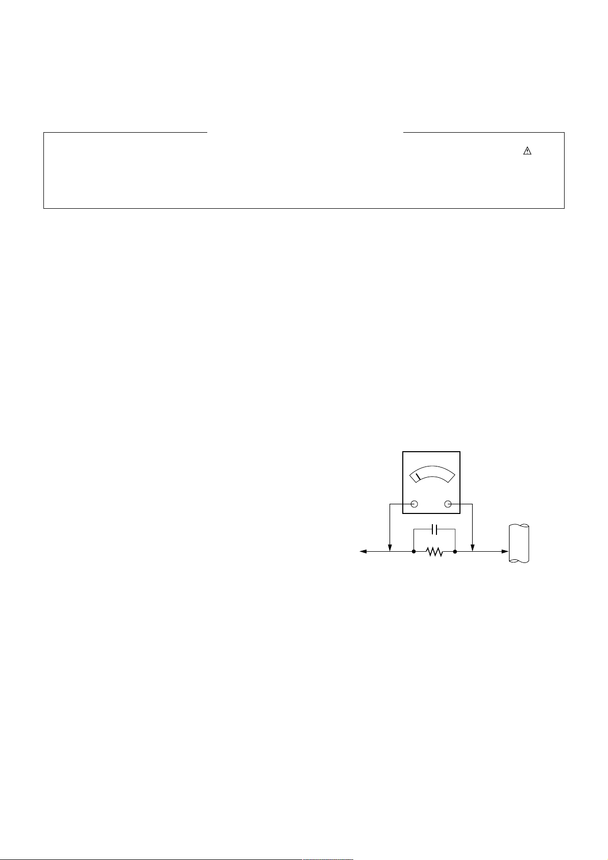
Leakage Current Hot Check (See below Figure)
Plug the AC cord directly into the AC outlet.
Do not use a line Isolation Transformer during this check.
Connect 1.5K/10watt resistor in parallel with a 0.15uF capacitor
between a known good earth ground (Water Pipe, Conduit, etc.)
and the exposed metallic parts.
Measure the AC voltage across the resistor using AC voltmeter
with 1000 ohms/volt or more sensitivity.
Reverse plug the AC cord into the AC outlet and repeat AC voltage
measurements for each exposed metallic part. Any voltage
measured must not exceed 0.75 volt RMS which is corresponds to
0.5mA.
In case any measurement is out of the limits specified, there is
possibility of shock hazard and the set must be checked and
repaired before it is returned to the customer.
Leakage Current Hot Check circuit
1.5 Kohm/10W
To Instrument's
exposed
METALLIC PARTS
Good Earth Ground
such as WATER PIPE,
CONDUIT etc.
AC Volt-meter
IMPORTANT SAFETY NOTICE
0.15uF
Page 4
- 4 -
LGE Internal Use OnlyCopyright©2007 LG Electronics. Inc. All right reserved.
Only for training and service purposes
SPECIFICATIONS
NOTE : Specifications and others are subject to change without notice for improvement
.
V Application Range
This spec is applied to the 50” PLASMA TV used PP7BA Chassis.
V Specification
Each part is tested as below without special appointment.
1) Temperature : 25±5°C (77±9°F), CST : 40±5
2) Relative Humidity: 65±10%
3) Power Voltage: Standard Input voltage (100-240V~, 50/60Hz)
* Standard Voltage of each product is marked by models.
4) Specification and performance of each parts are followed each drawing and specification by part number in accordance with SBOM.
5) The receiver must be operated for about 20 minutes prior to the adjustment.
V Test Method
1) Performance : LGE TV test method followed.
2) Demanded other specification
Safety : CE, IEC specification
EMC : CE, IEC
Chassis
PP7BA 50PT81-ZB EU LG
Model Name Market Brand Remark
50PT81-ZB Safety : IEC/EN60065, EMI : EN55013, EMS : EN55020EU
Model ApplianceMarket
TEST
Remark
V Module Specification1
Panel
PDP Module Outline Dimension 50X4
50X4P
Pixel Pitch 50X4
50X4P
Pixel Format 50X4
50X4P
Pixel Type
1
2
No Item Specification Remark
50” WXGA PDP
1190 x 703 x 52
1190 x 700 x 52
0.81 x 0.81 (1 pixel = 3 RGB cells)
0.81 x 0.81 (1 pixel = 3 RGB cells)
1366 x 768 Pixels RGB strip arrangement
1365 x 768 Pixels RGB strip arrangement
RGB Closed type
50X4P
(H)mm x (V)mm x (D)mm
mm
Page 5

- 5 -
LGE Internal Use OnlyCopyright©2007 LG Electronics. Inc. All right reserved.
Only for training and service purposes
V Module Specification2
Market
Broadcasting system
Available Channel
Receiving system
Operating Environment
Storage Environment
Power Consumption
Stand by
Frequency range
SCART Jack(2EA)
Video Input (1EA)
S-Video Input (1EA)
Component Input (1EA)
RGB Input (1EA)
HDMI Input (2EA)
RS-232C(1EA)
Audio Input (3 EA)
Audio variable out(1EA)
USB Input(1EA)
1
2
3
4
5
6
7
8
9
10
11
12
13
14
15
16
17
18
19
No Item Specification Remark
EU
PAL BG/I/DK, NTSC, SECAM
BAND PAL
VHF/UHF C1~C69
CATV S1~S47
Upper Heterodyne
1) Temp : 0 ~ 40 deg
2) Humidity : 10 ~ 90 %RH
1) Temp : -20 ~ 50 deg
2) Humidity : 10 ~ 90 %RH
Power on < 500
(Green)
Cool < 1W
Warm < 55W
H : 31 ~ 61Khz
V : 56 ~ 75Hz
PAL, SECAM
PAL, SECAM, NTSC
PAL, SECAM, NTSC
Y/Cb/Cr, Y/ Pb/Pr
RGB-PC
HDMI-PC, HDMI-DTV
Remote control, S/W Upgrade
PC Audio, Component (1EA),
SIDE AV(1EA)
DivX, MP3, JPEG
1/8W non-clipped max. audio signal.
Input voltage 198Vac/60HZ .
Full White video input.
PC Input
FULL SCART, HALF SCART
SIDE AV
SIDE S-VIDEO
L/R Input
SIDE(1EA)
Page 6
- 6 -
LGE Internal Use OnlyCopyright©2007 LG Electronics. Inc. All right reserved.
Only for training and service purposes
ADJUSTMENT INSTRUCTION
1. Application Object
These instructions are applied to all of the 50” PLASMA TV,
PP7BA Chassis.
2. Note
(1) Because this is not a hot chassis, it is not necessary to use
an isolation transformer. However, the use of isolation
transformer will help protect test instrument.
(2) Adjustment must be done in the correct order.
(3) The adjustment must be performed in the circumstance of
25±5°C of temperature and 65±10% of relative humidity if
there is no specific designation.
(4) The input voltage of the receiver must keep 100-220V~,
50/60Hz.
(5) Before adjustment, execute Heat Run for 30 minutes.
3. Adjustment items
3.1. PCB assembly adjustment items
(1) Channel memory
1) Download the channel data from BOM to EEPROM by
using LGIDS.
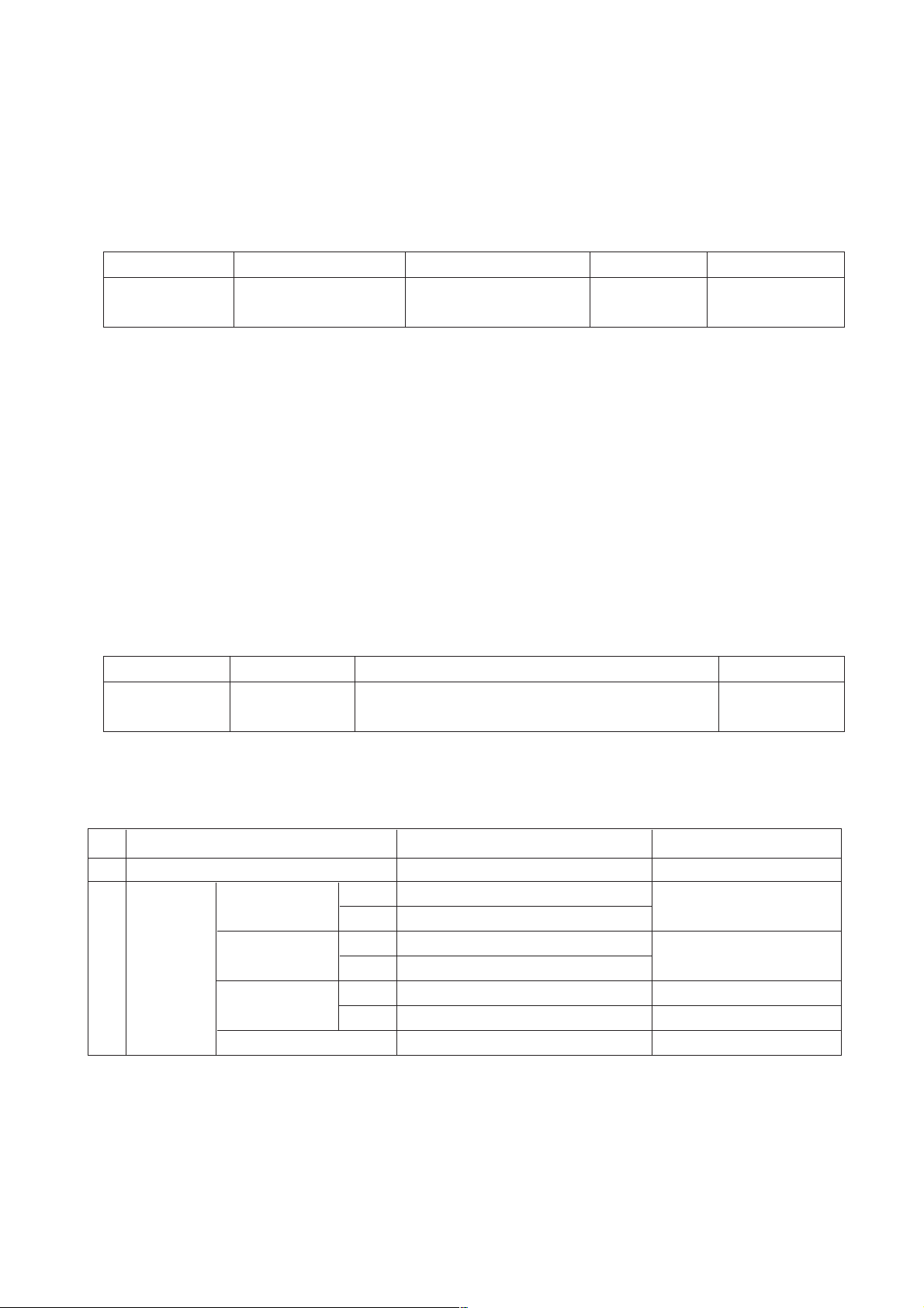
(2) Option adjustment following BOM
1) Push the ADJ key in the Adjust Remocon.
2) Input the Option Number that was specified in the BOM,
into the Shipping area.
3) Select “Tool Option1/ Tool Option2/ Area Option” by
using
D/E
(CH+/-) key, and press the number key(0~9)
consecutively.
ex) If the value of Tool Option1 is 7, input the data using
number key “7”(Fig.1).
(3) Color carrier Adjustment.
3.2. SET assembly adjustment items
(1) Auto AV Color Balance.
(2) Adjustment of White Balance.
(3) Auto Component Color Balance adjustment.
- standard equipment : MSPG925FA.
(4) Auto RGB Color Balance adjustment.
- standard equipment : MSPG925FA
( At DVR model Case, Please check DVR function like
following list )
(5) Checking DVR Function and HDD
* Check DVR Function as follow on 4-2 and find HDD failure
under malfunction.
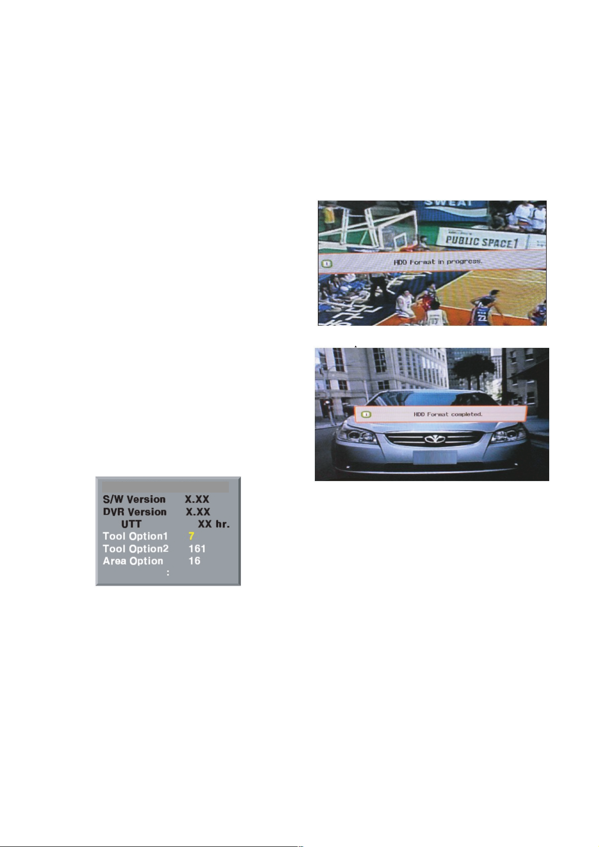
4. HDD assembly adjustment method
4-1. HDD Format
1) Assemble MAIN , DVR Board.
2) HDD Format in progress words will create automatically.
3) Please, wait for 30~40 seconds.
(1) HDD Format in progress.
(2) HDD Format completed.
4-2. Sub Program Download for “DVR” by
using USB memory stick
(1) Connect USB memory stick to SET.
(2) Set power off -> On
- DVR s/w will be installed automatically.
PPBA/BB 50X4PPPBA/BB 50X4P WXGA WXGA
(Fig.1)
Page 7
- 7 -
LGE Internal Use OnlyCopyright©2007 LG Electronics. Inc. All right reserved.
Only for training and service purposes
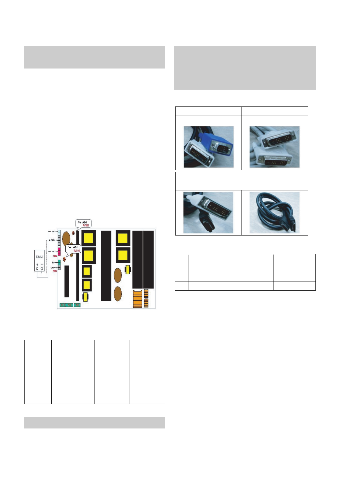
5. POWER PCB Assy Voltage
Adjustments (Va, Vs Voltage adjustments)
5-1. Test Equipment : D.M.M. 1EA
5-2.Connection Diagram for Measuring
: refer to Fig.2
5-3. Adjustment Method
(1) Va Adjustment
1) After receiving 100% Full White Pattern, HEAT RUN.
2) Connect + terminal of D.M.M to Va pin of P812, connect
- terminal to GND pin of P812.
3) After turning VR501, voltage of D.M.M adjustment as
same as Va voltage which on label of panel right/top.
(Deviation; ±0.5V)
(2) Vs Adjustment
1) Connect + terminal of D.M.M to Vs pin of P812, connect
– terminal to GND pin of P812.
2) After turning VR401, voltage of D.M.M adjustment as
same as Va voltage which on label of panel right/top.
(Deviation; ±0.5V)
6. ADC Calibration
* Press the FRONT-AV Key on R/C for converting input mode.
(Change RS-232 Host : pc, BaudRate : 115200bps)
7. EDID
7-1. EDID Data
Each PCB assembly must be checked by check JIG set.
(Because power PCB Assembly damages to PDP Module,
especially be careful)
* Use the proper signal cabel for EDID Download
- Analog EDID : Pin3 exists
- Digital EDID : Pin3 exists
* Never connect HDMI & DVU-D & DVI-A Cable at the same time.
* Use the proper cables below for EDID Writing
* HDMI 1 and HDMI2 is different each other. So you have to
Download different EDIT File.
(Fig.2) Connection diagram of power adjustment for measuring
For Analog EDID
D-sub to DVI-I DVI-D to DVI-D
For Digital EDID
For HDMI EDID
DVI-D to HDMI or HDMI to HDMI
1
2
3
Manufaturer
Version
Revision
GSM
Digital : 1
Digital : 3
1E6D
01
03
ConditionItemNo Hex Data
MSPG925FA
Component RGB-PCRF/AV/S-VIDEOADC
Model : 60
(1024*768 60Hz)
Pattern : 65
*100% Color Bar
Model:217(720P)
Pattern : 65
*100% Color Bar
PAL
INPUT AV1 - TB
SELECT AV3 - ZF
Model : 202
(PAL-BGDHI)
Pattern : 65
*100% Color Bar
- System control RS-232 Host should be “PC“ for adjustment.
Page 8

- 8 -
LGE Internal Use OnlyCopyright©2007 LG Electronics. Inc. All right reserved.
Only for training and service purposes
7-2. Analog(256Byte)
(1) BLOCK1(128Byte)
7-3. HDMI(256Byte)
(1) BLOCK1(128Byte)
(2) BLOCK2(128Byte)
=> Detail EDID Options are below([1], [2], [3],[4], [5])
1. [1]-Product ID
2. [2]-Serial No : Controlled on production line
3. [3]-Month, Year : Controlled on production line
ex) Week : '03' => '03'
Year : '2005' => '0F'
4. [4]-Model Name(Hex):
5. [5]-Checksum : Changeable by total EDID data
8. Adjustment of RF/AV/S-VIDEO
8-1. Requirement
(1) This AV color balance adjustment should be performed
before white Balance Adjustment.
(2) After AV color balance adjustment, Change the mode from
AV to RF.
8-2. Required Equipment
(1) Remote controller for adjustment.
(2) 802F Pattern Generator, Master(MSPG-925FA), etc.
(3) MSPG-925FA Pattern Generator.
(Which has Video Signal : 100% Color Bar Pattern shown in
Fig.3)
-> Model : 202 / Pattern : 65
8-3. Method of Auto RF/AV/S-VIDEO Color
Balance
(1) Press the FRONT-AV KEY on R/C for converting input
mode.
(2) Input the Video Signal: 100% Color Bar signal into AV.
(3) Set the PSM to Dynamic mode in the Picture menu.
(4) Press INSTART key on R/C for adjustment.
(5) Press the
G(Vol.+) key to operate the set, then it becomes
automatically.
(6) Auto-RGB OK means the adjustment is completed.
(Fig. 3)
1
2
3
4
4
5
1
1
2
3
4
4
5
Model
Name
42PB4RT
50PB4RT
42PT81
50PT81
Product ID
Product ID
EDID tableHex
LG TV
00 00 00 FC 00 4C 47 20 54 56 0A 20 20 20 20 20 20 20
Model Name
Page 9

9. Adjustment of Component
9-1. Required Equipment
(1) Remote controller for adjustment.
(2) 802F Pattern Generator, Master(MSPG-925FA), etc.
(3) MSPG-925FA Pattern Generator.
(Which has 720P@60Hz YPbPr Signal : 100% Color Bar
Pattern shown in Fig.4)
-> Model : 217 / Pattern : 65
(4) It is very import to use correct adjustment pattern like
Fig.4.
1) Within the pattern, color sequence should be aligned
: White-Yellow-Cyan-Green-Gray-Red-BLUE-BLACK
( If color sequence is reversed (Black -> ...-> White),
reverse the pattern with REV key, when using Master
pattern generator like MSPG-925)
2) If Minimum Black Level and/or Maximum White Level is
not correct, Do select 100% Color Bar Pattern.
9-2. Method of Auto Component Color Balance
(1) Input the Component 720p 100% Color Bar(MSPG-925FA
model:217, pattern:65) signal into Component.
(2) Set the PSM to Dynamic mode in the Picture menu.
(3) Press the INSTART key on R/C for adjustment.
(4) Press the
G(Vol.+) key to operate the set , then it
becomes automatically.
(5) Auto-RGB OK means the adjustment is completed.
10. Adjustment of RGB
10-1. Required Equipment
(1) Remote controller for adjustment.
(2) 802F Pattern Generator, Master(MSPG-925FA), etc.
(3) MSPG-925FA Pattern Generator.
(Which has XGA [1024*768] 60Hz PC Format output signal :
100% Color Bar Pattern shown in Fig.5)
(4) It is very import to use correct adjustment pattern like
Fig.5.
1) Within the pattern, color sequence should be aligned
: White-Yellow-Cyan-Green-Gray-Red-BLUE-BLACK
( If color sequence is reversed (Black -> ...-> White),
reverse the pattern with REV key, when using Master
pattern generator like MSPG-925)
2) If Minimum Black Level and/or Maximum White Level is
not correct, Do select 100% Color Bar Pattern.
10-2. Method of Auto RBG Color Balance
(1) Input the Component 720p 100% Color Bar(MSPG-925FA
model:217, pattern:65) signal into Component.
(2) Set the PSM to Dynamic mode in the Picture menu.
(3) Press the INSTART key on R/C for adjustment.
(4) Press the
G(Vol.+) key to operate the set , then it
becomes automatically.
(5) Auto-RGB OK means the adjustment is completed.
- 9 -
LGE Internal Use OnlyCopyright©2007 LG Electronics. Inc. All right reserved.
Only for training and service purposes
(Fig. 4)
(Fig. 4)
Page 10
- 10 -
LGE Internal Use OnlyCopyright©2007 LG Electronics. Inc. All right reserved.
Only for training and service purposes
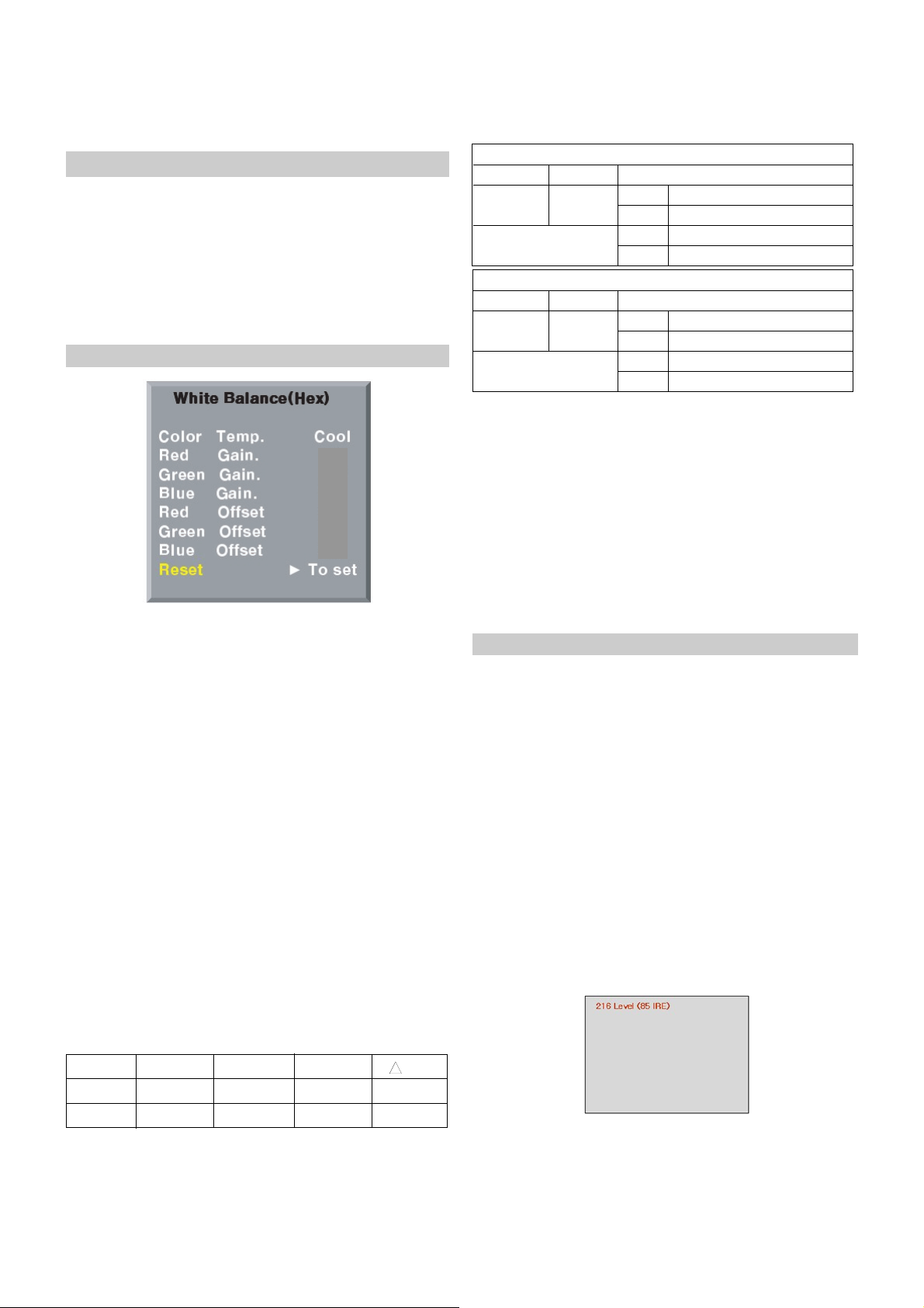
11. White Balance
* Notice
- Do the white balance adjustment under the 10LUX
- Before white balance, press the In-start key 2times and do
the reset like Fig.6
- Use the Torino inner pattern(216 gray pattern)
- To enter White-balance mode,press the IN-START key
2times.
11-1. Test Equipment
(1) Color Analyzer (CA-100),CA-210.
* Note : When using the Color Analyzer with PDP,
recommend the CA-100 more than CA-210.
If CA-100 can not available, it is also good th use
the CA-210
(2) PC(for communication through RS-232C)
-> UART Baud rate : 115200.
(3) Pattern Generator(MSPG-925FA etc.)
11-2. Color Temperature & Color
Coordinates Setting
(1) When adjusting the Color Temperature of PDP, Color
Analyzer CA-210(Matrix should be corrected through
CH10 of CS-1000) should be used. When CA-210 have
used, it don’t need to fit the CH10.
(2) Adjust the Color Temperature based below adjustment
color coordinates.
(3) Even if CH9 of CA-210 is corrected with Matrix, there may
be many character of Module and Filter.
(4) Therefore Refer to the below Color Coordinates Target.
But, in case of WCG module, use the CH12 of CA-210.
W Target Value CA-210(CH10), CA-100
( R/G/B gain and R/G/B offset Default values are different in
according to using module)
W
Target Value of Brightness, Color Coordinates, Color Temperature
11-3 .Manual white Balance (INNER Pattern)
(For White Balance, Adjust twice, Cool and Warm)
(1)
Execute CA-100, CA-210(10CH) or CA-100 Zero Calibration.
(2) Use torino inner pattern as below Fig.7, Supply 216Level
(85 IRE) full screen pattern
(3) Enter the White Balance adjustment mode by pressing the
INSTART key twice(White Balance) on R/C.
(4) Stick sensor to center of the screen and select each items
(Red/Green/Blue Gain and Offset) using
D/E (CH+/-) key
on R/C.
(5) Adjust with R / G / B Gain using
F/G (VOL+/-) key on R/C.
(6) Adjust it until color coordination becomes as below.
W Color Temperature : Cool, Medium, Warm
(1) One of R/G.B Gain should be fixed at 80 and adjust two
Gain Value with decreasing the Default values from 80
1) When R Gain is Fixed at Default value(80)
- Adjust G gain and B gain with decreasing Default values
from 80
2) When B Gain is Fixed at Default value(80)
- Adjust R gain and G gain with decreasing Default values
from 80
3) When G Gain is Fixed at Default value(80)
- Adjust R gain and B gain with decreasing Default values
from 80
(2) R/G/B Gain and R/G/B Offset Default Value.
- Red Gain : 80
- Green Gain : 80
- Blue Gain : 80
(Fig.6)
80
8080
80
7D
8080
8C
- Before White-balance, the AV ADC should be done.
- System control RS-232 Host should be “PC“ for adjustment.
- After All adjustment is completed, Please push “Instop” Key.
Temp x
0.276±0.002
0.313±0.002
0.283±0.002
0.329±0.002
+0.000
+0.003
11,000K
6,500K
COOL
WARM
CSM y
uv
High Light
High Light
60 ± 20cd/m2(42XGA)
Cool X: 0.276±0.002, Y: 0.283±0.002
Normal X: 0.313±0.002, Y: 0.329±0.002
Cool 11,000±500K
Warm 6,500K±500K
Brightness
Color
-Coordinate
Desired result (216 Gray)
(Fig.7)
Color Temperature
High Light
High Light
50 ± 20cd/m2(80% of non-high altitude)
Cool X: 0.276±0.002, Y: 0.283±0.002
Normal X: 0.313±0.002, Y: 0.329±0.002
Cool 11,000±500K
Warm 6,500K±500K
Brightness
Color
-Coordinate
Desired result for high altitude(216 Gray)
Color Temperature
Page 11

- 11 -
LGE Internal Use OnlyCopyright©2007 LG Electronics. Inc. All right reserved.
Only for training and service purposes
11-4 .Auto white Balance (INNER Pattern)
Input Select
R-Gain_Normal
G-Gain_Normal
B-Gain_Normal
R-Gain_Warm
G-Gain_Warm
B-Gain_Warm
R-Gain_Cool
G-Gain_Cool
B-Gain_Cool
R-Offset_Normal
G-Offset_Normal
B-Offset_Normal
R-Offset_Warm
G-Offset_Warm
B-Offset_Warm
R-Offset_Cool
G-Offset_Cool
B-Offset_Cool
COLOR TEMP.
Inner Pattern Signal
x
j
j
j
j
j
j
j
j
j
l
l
l
l
l
l
l
l
l
k
w
b
a
b
c
d
e
f
g
h
i
j
k
l
m
n
o
p
q
r
u
b
00
00
00
00
00
00
00
00
00
00
00
00
00
00
00
00
00
00
00
00
00
00h
01h
10h
11h
20h
21h
40h
41h
60h
90h
Min
00h
00h
00h
00h
00h
00h
00h
00h
00h
00h
00h
00h
00h
00h
00h
00h
00h
00h
00h
00
10
ff
Max
80h
80h
80h
80h
80h
80h
80h
80h
80h
80h
80h
80h
80h
80h
80h
80h
80h
80h
03h(Cool,Normal,Warm,User)
W/B Adjustment Start
Using Internal Pattern W/B
Adjustment Completion
DTV-Air
Cable
RF-Air
Cable
AV1
AV2
COMP1
COMP1
RGB-PC
HDMI
INIT
80h
80h
80h
80h
80h
80h
80h
80h
80h
No Command1 Command2 Set ID
Data
Mode
Page 12

- 12 -
LGE Internal Use OnlyCopyright©2007 LG Electronics. Inc. All right reserved.
Only for training and service purposes
W
Input Select Data
: RF(10), AV1~4(20,21,22,23), SAV(30), COMP(40), DVI(50 or 60), HDMI(90)
W
Command Set
( SET ID : 0 -> ALL, 1~99 -> each SET )
1
2
3
4
5
6
7
8
9
10
11
12
13
14
15
16
17
18
19
20
21
22
23
24
25
POWER ON/OFF
MAIN INPUT
ARC
SCREEN MUTE
AUDIO MUTE
VOLUME
CONTRAST
BRIGHTNESS
COLOR
TINT
SHARPNESS
OSD ON/OFF
CHILD LOCK
PIP MODE
PIP ARC
PIP POSITION
TREBLE
BASS
BALANCE
COLOR TEMP.
RED LEVEL
GREEN LEVEL
BLUE LEVEL
PIP INPUT
CURRENT STATE
KA(ka)
XB(xb)
KC(kc)
KD(kd)
KE(ke)
KF(kf)
KG(kg)
KH(kh)
KI(ki)
KJ(kj)
KK(kk)
KL(kl)
KM(km)
KN(kn)
KO(ko)
KQ(kq)
KR(kr)
KS(ks)
KT(kt)
KU(ku)
KV(kv)
KW(kw)
K$(k$)
XY(xy)
KZ(kz)
0~99
0~99
0~99
0~99
0~99
0~99
0~99
0~99
0~99
0~99
0~99
0~99
0~99
0~99
0~99
0~99
0~99
0~99
0~99
0~99
0~99
0~99
0~99
0~1
10~90
1~8
0~1
0~1
0~64
0~64
0~64
0~64
0~64
0~64
0~1
0~1
0~3
0~64
0~64
0~64
0~3
0~50
0~50
0~50
10~90
FF
0: OFF, 1:ON
RF(10), AV1~4(20,21,22,23),
SAV(30), COMP(40),
RGB(50 or 60), HDMI(90)
4:3; 16:9; SPECTACLE; ZOOM;
ORIGINAL; 14:9; FULL
1: MUTE, 0: MUTE OFF
1: MUTE, 0: MUTE OFF
0: 0, 64 : 100 (Hexadecimal)
0: 0 , 64 : 100 (Hexadecimal)
0: 0 , 64 : 100 (Hexadecimal)
0: 0 , 64 : 100 (Hexadecimal)
0: R50 , 64 : G50 (Hexadecimal)
0: 0 , 64 : 100 (Hexadecimal)
0: OFF, 1: ON
1: LOCK, 0: OFF
PIP_OFF, PIP, DW1, DW2
NOT USED
NOT USED
0:0 , 64:100
0:0 , 64:100
0:L50, 64:R50
COOL, NORMAL, WARM, USER
0 : -40, 50 : 40
0 : -40, 50 : 40
0 : -40, 50 : 40
RF(10), AV1~4(20,21,22,23),
SAV(30), COMP(40),
DVI(50 or 60), ,HDMI(90)
ACK is 0, there is Signal
ACK is 1, there is No Signal
ACK is 2, power Off Status
No Adjustment contents CMD SET ID
VAL
Specification
Page 13

- 13 -
LGE Internal Use OnlyCopyright©2007 LG Electronics. Inc. All right reserved.
Only for training and service purposes
26
27
28
29
30
31
32
33
34
35
36
37
RED GAIN
GREEN GAIN
BLUE GAIN
RED OFFSET
GREEN OFFSET
BLUE OFFSET
AUTO CONFIG.
SELECT PR.
SELECT SUB PR.
IR CODE
Red,Blue,Green Gain
Red,Blue,Green offset
WHITE BALANCE “J”(A~F)
TUNER CONTROL
ADC Calriblation
FACTORY IR
JA
JB
JC
JD
JE
JF
JU
MA
MB
MC
Ja,Jb,Jc
Jd,Je,Jf
0~99
0~99
0~99
0~99
0~99
0~99
0~99
0~99
0~99
0~99
00<E0
00<90
0~3F
0~3F
0~3F
0~3F
0~3F
0~3F
01
0~C7
0~C7
Over F0
Min:00
Max:fe
Min:00
Max:fe
0:0, 3F:3F , FF: Current State
0:0, 3F:3F , FF: Current State
0:0, 3F:3F , FF: Current State
0:0, 3F:3F , FF: Current State
0:0, 3F:3F , FF: Current State
0:0, 3F:3F , FF: Current State
The state is not Auto Adjust Condition
Send NACK
0: Pr. 0, C7: Pr.199
0: Pr. 0, C7: Pr.199
IR CODE 0, BITMASK = 0X01
Initial Value : red -0x79
blue -0x6f
green -0x80
Initial Value : red -0x80
blue -0x82
green -0x80
No Adjustment contents CMD SET ID
VAL
Specification
Page 14
- 14 -
LGE Internal Use OnlyCopyright©2007 LG Electronics. Inc. All right reserved.
Only for training and service purposes
Tool Option1
Tool Option2
Area Option Option1
Option2
Option3
Option4
System Control1
System Control2
System Control2
Power-off History
Panel Control
Fan Control
Maker
Inch
Tool
Tuner Num.
EYE
INDEX
VFD
HDMI Type(A)
Rear AV
BOOST
Full
Soft Touch
Reserved
CMO
50
Option Detail List
Data
Remark
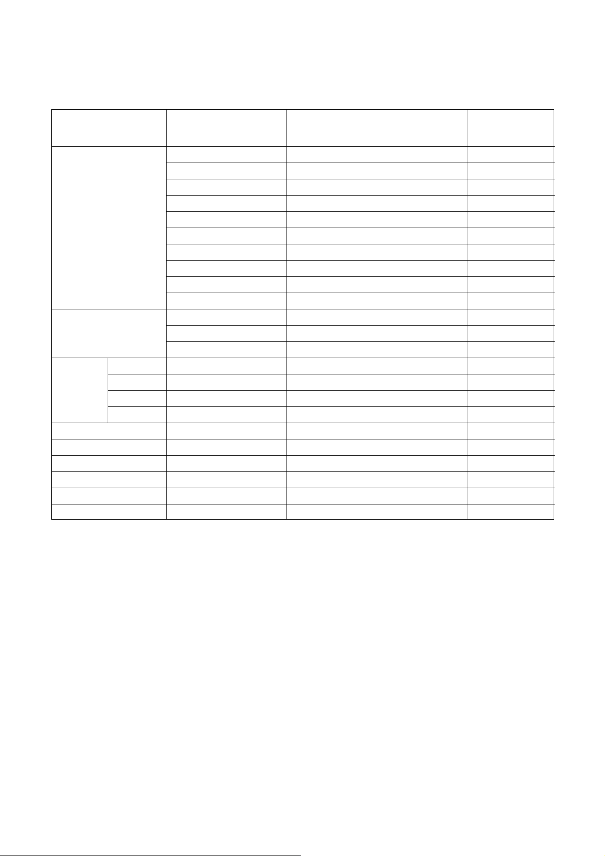
12. Detail list of SVC Option data
Page 15

- 15 -
LGE Internal Use OnlyCopyright©2007 LG Electronics. Inc. All right reserved.
Only for training and service purposes
13. Shipped condition
(1) 1) Push the IN-START key in a Adjust Remocon.
(2) Input the Option Number that was specified in the BOM, into the Shipping area.
(3) The work is finished, Push
V Key.
1
2
3
4
5
6
STATION Auto Tuning
Manual Tuning
Promgrame Edit
Favourite Prog.
PICTURE Picture Mode
Color Temperature
XD
Advanced
Aspect Ratio
Picture Reset
Screen
XD Demo
SOUND Sound Mode
Auto Volume
Balance
TV Speaker
TIME Clock
Off Time
On Time
Sleep Time
Auto Sleep
STATION SPECIAL Language
Country
Input Label
SIMPLINK
Key Lock
Set ID
DVR Time Control
Recorded TV
Manual Recording
Scheduled List
Video Quality
HDD Format
System/Storage From/Start
Storage/System/Band/Channel/Fine/S
earch/Name
To Set
-- -- --
Dynamic/Standard/Mild/User1/User2
Cool
Auto
Cinema : Off
Black Level : Disable
Spectacle/Full/Original/4:3/
16:9/14:9/Zoom1/Zoom2
To Set
Disable
Disable
SRS TSXT/ Standard/ Music/
Movie/ Sports/ User
Off
0
On
Year -- : --
Date -- : --
Time -- : --
Off
00 : 00
Off
00 : 00
Volume 30
Programme 0
Off
Off
To Set
To Set
To Set
Off
Off
Off
On
To Set
To Set
To Set
High
To Set
No Item
Condition
Remark
Page 16
- 16 -
LGE Internal Use OnlyCopyright©2007 LG Electronics. Inc. All right reserved.
Only for training and service purposes
TROUBLESHOOTING
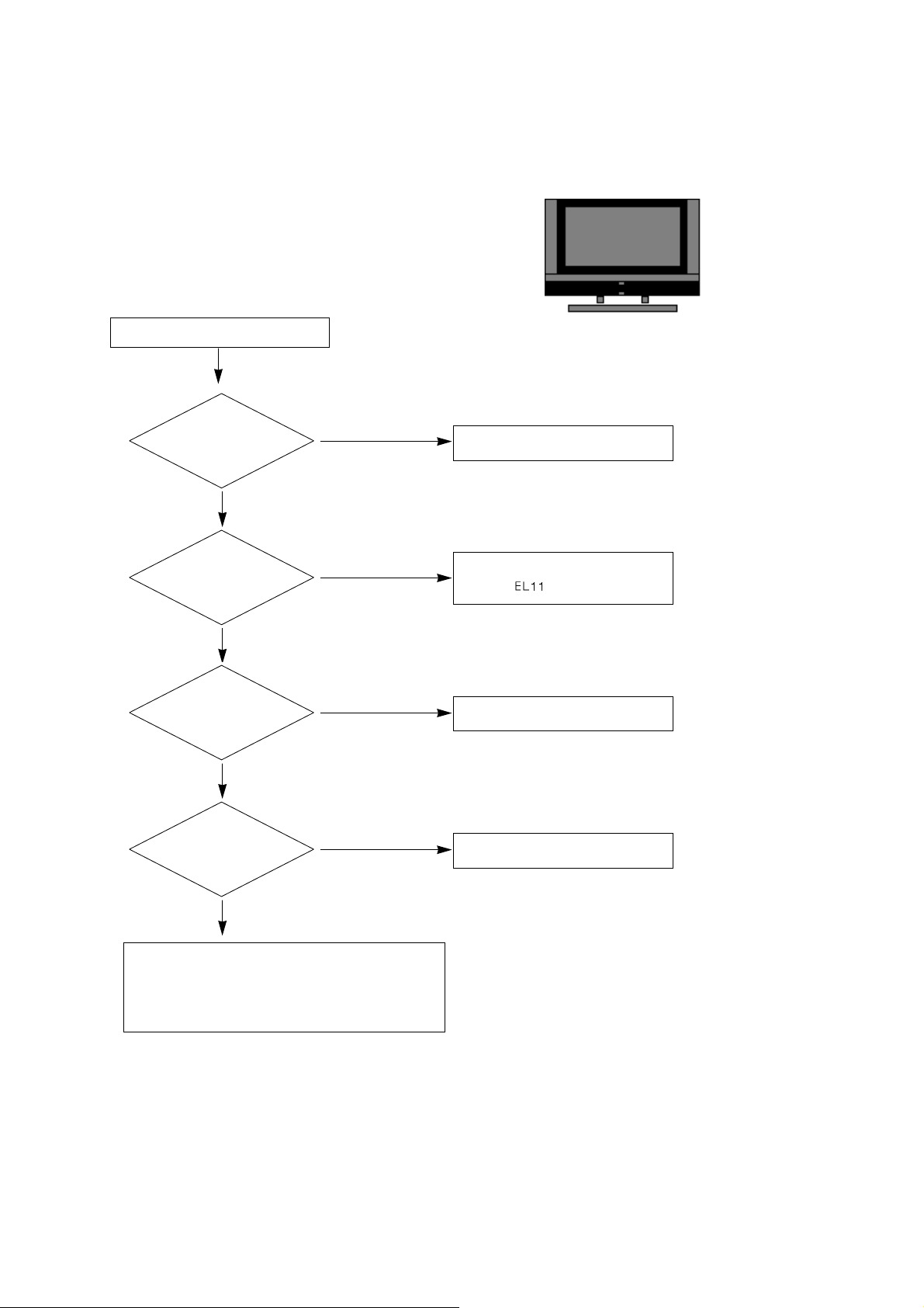
1. No power
(1) Symptom
1) Minute discharge does not occur at module.
2) Front LED does not activate.
(2) Press check
Plug in the power cord
Start Check
No
Yes
Is the power cord
plugged in?
Connect the cable.
Plasma(
)
No
Yes
Are the line filter and
PSU connected?
Replace the fuse.
No
Yes
Is the
correct fuse for
the PSU in place?
Plasma(F101)
Connect the 13pin cable.
After remove all cables connected PSU(except the
CN101), authorizes the AC voltage marking manual.
If the ST-by 5V does not operate, replace the PSU.
No
Yes
Is the PSU and 13pin
cable connected to the
VSC board?
Page 17
- 17 -
LGE Internal Use OnlyCopyright©2007 LG Electronics. Inc. All right reserved.
Only for training and service purposes
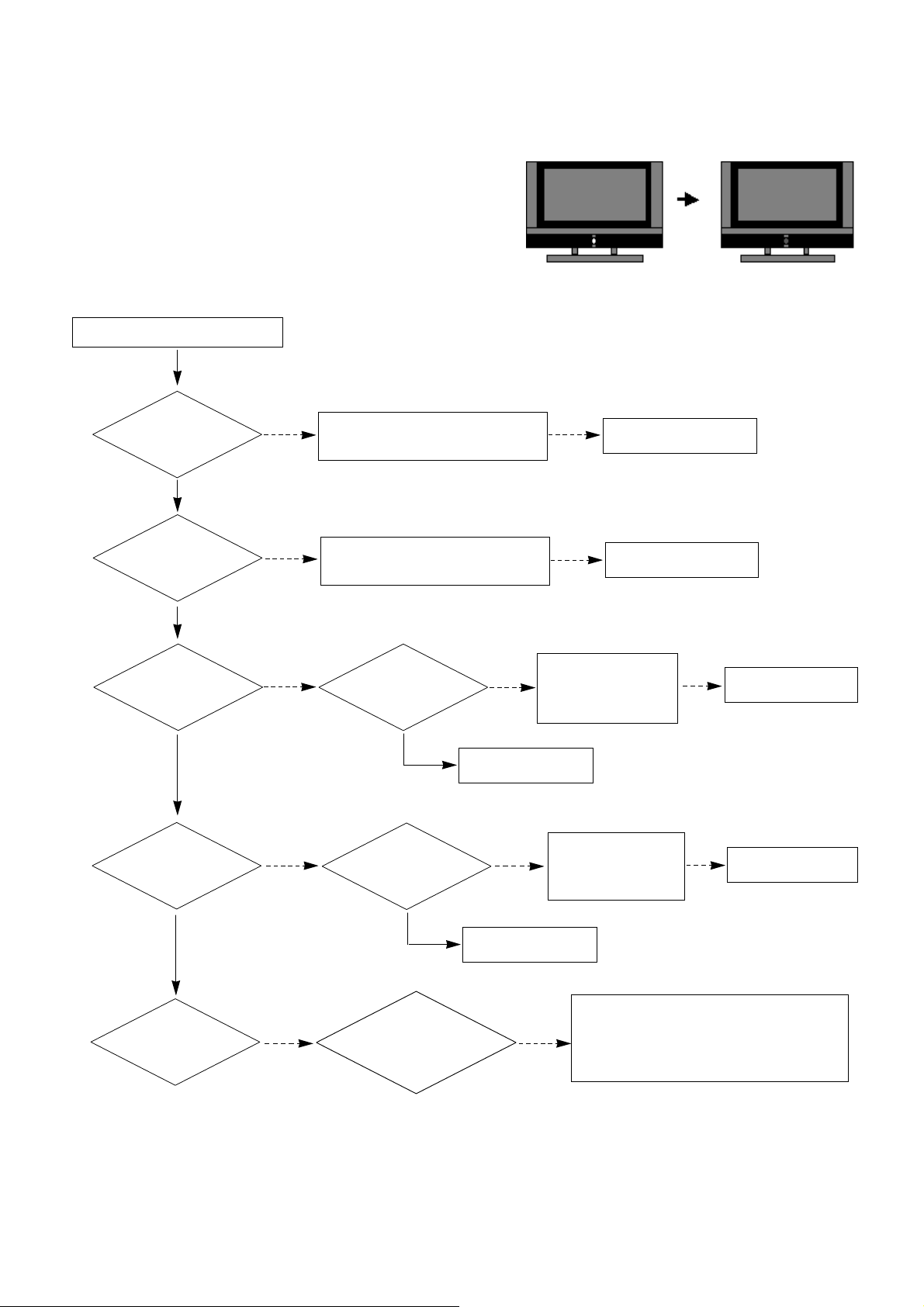
2. Protect mode
(1) Symptom
1) After lighting once it does not discharge minutely from the module.
2) The relay falls.(there is an audible “Click”.)
3) The color of the front LED turns from green to red.
(2) Follow check
Is the PSU normal ?
Replace Power Board.
Is the output the normal Low/High
voltage except for the Stand-by 5V?
Yes
No
No
Are all the connectors
normal?
Replace the connector.
Replace the fuse.
Replace the Y-Board.
After checking each connector does
is operate correctly?
Yes
No
No
Is the Y-Board
normal?
Is the appropriate
fuse (FS2,FS3) on the
Y-B/D?
Is the output voltage
normal after removing
the P1 connector of
the Y-B/D?
Yes
No
No
Replace the Z-Board.
Is the Z-Board
normal?
Is appropriate
fuse (FS1,FS2) on
the Z-B/D?
Is the output voltage
normal after removing
the P1 connector of
the Z-B/D?
Yes
No
No
Is the X- Board
normal?
Is the
output voltage normal
after removing the P100, 110,
200, 210 connector of
the X-B/D?
After removing the P100, 110 and the output
voltage is normal : Replace the Right X-B/D
After removing the P200, 210 and the output
voltage is normal : Replace the Left X-B/D
No
Yes
Replace the fuse.
Yes
Start Check
Page 18

- 18 -
LGE Internal Use OnlyCopyright©2007 LG Electronics. Inc. All right reserved.
Only for training and service purposes
3. No Raster
(1) Symptom
1) No OSD or image are displayed on the screen.
2) It maintains the condition where the front LED is green.
(2) Follow check
Check the PDP Module
Replace the
Power board.
Does
minute discharge
at Module?
Is the inverter
/VaVs on?
Is output the normal
Low/High voltage except
for the Stand-by 5V?
Yes
No
No
Is there a fault with
the link cable?
Yes
Is the output for the
IC700 normal?
Reconnect the link cable in P600.
No
Replace the VSC.
No
Yes
Start Check
Page 19

- 19 -
LGE Internal Use OnlyCopyright©2007 LG Electronics. Inc. All right reserved.
Only for training and service purposes
4. In the case an unusual display in RF mode(Main).
Check the power.(L1004)
Is the
video output of the
CXA2069Q normal? (Check R324,
in case of S-Video
Check R324,
R328)
Is the
input voltage
normal?(Check
L308)
Yes
No
Yes
Is the LVDS
Cable connected?
Yes
Change the IC(IC700)
Re-insert the cable.
No
Check the IC.(IC300)
No
A
Check the power.
Is the
video output of the
Tuner normal? (Check
TU200_Pin14)
Is the
input voltage
normal?(Check Pin8,
Pin6)
Is the I2C communication
normal?
(Check Pin5, Pin4)
Yes
No
Yes
No
Check the Tuner.
No
Re-insert the cable.
Is the
Tuner Cable
connected?
No
No
Is the
I2C communication
normal? (Check
R309, R310)
No
5. In the case of an unusual display in rear AV mode(Main).
Is video input of
the A/V jack normal?
Yes
Sam as Block A
Check the input source.
No
Page 20

- 20 -
LGE Internal Use OnlyCopyright©2007 LG Electronics. Inc. All right reserved.
Only for training and service purposes
6. In the case of an unusual display in rear S-Video mode(Main).
Is the video input
of the A/V jack normal?
Yes
Sam as Block A
Check the input source.
No
7. In the case of an unusual display in Side AV mode(Main).
Is the video input
of the A/V jack normal?
Yes
Sam as Block A
Check the input source.
No
8. In the case of an unusual display in Side S-Video mode(main).
Is the video
input of the A/V jack
normal? (Check R339,
R341,L310)
Yes
Sam as Block A
Check the input source.
No
Page 21

- 21 -
LGE Internal Use OnlyCopyright©2007 LG Electronics. Inc. All right reserved.
Only for training and service purposes
9. In the case of an unusual display in SCART 1 mode(main).
Is the video
input of the A/V jack
normal?(Check R102)
Yes
Sam as Block A
Check the input source.
No
10. In the case of an unusual display in SCART 1_RGB mode(main).
Is the
video input of
the A/V jack normal?(Check
L111, L112,
L112)
Yes
Sam as Block A
Check the input source.
No
11. In the case of an unusual display in SCART 2 mode(main).
Is the video input of
the A/V jack normal?
(Check R115)
Yes
Sam as Block A
Check the input source.
No
Page 22

- 22 -
LGE Internal Use OnlyCopyright©2007 LG Electronics. Inc. All right reserved.
Only for training and service purposes
12. In the case of an unusual display in SCART 2_YC mode(main).
Is the video
input of the A/V jack
normal?(Check
R115,R149)
Yes
Sam as Block A
Check the input source.
No
13. In the case an unusual display in RF mode(Sub).
14. In the case PIP doesn’t display in other mode(Sub).
- Same as the case of main except block A should be change to B
Check the power.(L1004)
Is the
video output of the
CXA2069Q normal? (Check R312,
in case of S-Video
Check R312,
R314)
Is the
input voltage
normal?(Check
L308)
Yes
No
Yes
Is the LVDS
Cable connected?
Yes
Change the IC(IC700)
Re-insert the cable.
No
Change the IC(IC300).
No
B
Check the power.
Is the
video output of the
Tuner normal? (Check
TU201_Pin14)
Is the
input voltage
normal?(Check Pin8,
Pin6)
Is the I2C communication
normal?
(Check Pin5, Pin4)
Yes
No
Yes
No
Check the Tuner.
No
Re-insert the cable.
Is the
Tuner Cable
connected?
No
No
Is the
I2C communication
normal? (Check
R309, R310)
No
Page 23

- 23 -
LGE Internal Use OnlyCopyright©2007 LG Electronics. Inc. All right reserved.
Only for training and service purposes
15. In the case of an unusual display in component 1 mode(main/sub).
Is the video
input of the JK102
normal? (Check L126,
L127,L128)
Yes
Change the IC(IC700)
Check the input source.
No
16. In the case of an unusual display in component 2 mode(main/sub).
Yes
Change the IC(IC700)
Check the input source.
No
Is the video
input of the Jk103 normal?
(Check L129, L130,
L131)
17. In the case of an unusual display in RGB mode(main/sub).
Yes
Change the IC(IC700)
Check the input source.
No
Is the
R, G, B input
and H, V sync of the
JK500 normal?(Check R509,
R511, R512, R513,
R515)
Page 24

- 24 -
LGE Internal Use OnlyCopyright©2007 LG Electronics. Inc. All right reserved.
Only for training and service purposes
18. No Sound
(1) Symptom
1) LED is green.
2) There is a picture but no sound.
(2) Follow check
Is there sound in any
mode?
Is the speaker
on?
Yes
Yes
Is the speaker
cable normal?
Yes
Yes
Is there no sound
only for HDMI?
Yes
Is there no
sound only AV?
Is the output
of IC300(Pin52,53)
normal?
Yes
Is there no sound
only for RF?
No
No
No
No
Download the EDID data.
Set speaker on
in the menu.
No
Replace the
IC300
No
Check the Speaker
cable
No
Is the IC400
operating normal?
Replace the IC400
No
Yes
Is the IC401
operating normal?
Replace the IC401
Replace the VSC B/D
Yes
Check the signal after IC300.
refer to circuit diagram.
Check the Tuner In/Out.
No
Yes
Is the IC402
operating normal?
Replace the IC402
No
Page 25

- 25 -
LGE Internal Use OnlyCopyright©2007 LG Electronics. Inc. All right reserved.
Only for training and service purposes
19. HDMI mode
Is only video
normal?
Is only audio
normal?
No
Yes
Download EDID data each port.
Check the TMDS line wave.
(R1215~R1222 / R1226~R1233)
1. Check the HDMI receiver’s status register. (0x60, offset 0x06)
- If the value is 0xf or 0x8, it is normal.
2. Check the HDCP register. (0x6, offset 0x32)
- Enable bit 6 : HDCP key loaded
- Enable bit 5 : HDCP decryption active
- Enable bit 4 : HDCP authentication attempted
Reset TMDS power down/ on register.
- 0x60, offset 0x3f : 0xf7 => 0xff
Check HDMI source.
Change to another source or cable.
Yes
Is the wave
continuous?
Normal video,
Normal audio?
No
Yes
Replace the IC1200.
No
1. Check TV input mode.
(HDMI 1 port support HDMI and DVI.
So if you input DVI signal and PC audio from
phone jack, You can hear PC audio.)
2. Unplug and plug in the HDMI cable.
(sometimes ESD surge occurred at HDMI port.)
3. Check the HDMI Mute register. (0x68, offset 0x37)
4. Check the Audio-out channel mute register (0x68,
offset 0x32) is appropriately enabled.
Yes
Page 26

- 26 -
LGE Internal Use OnlyCopyright©2007 LG Electronics. Inc. All right reserved.
Only for training and service purposes
BLOCK DIAGRAM
Page 27

MEMO
- 27 -
LGE Internal Use OnlyCopyright©2007 LG Electronics. Inc. All right reserved.
Only for training and service purposes
Page 28

- 28 -
LGE Internal Use OnlyCopyright©2007 LG Electronics. Inc. All right reserved.
Only for training and service purposes
EXPLODED VIEW
590
901
900
121
570
310
560
120
601
602
603
501
520
550
301
300
302
303
600
304
305
306
400
202
203
240
204
205
206
250
208
101
580
207
201
200
A21
A2
502
Page 29

- 29 -
LGE Internal Use OnlyCopyright©2007 LG Electronics. Inc. All right reserved.
Only for training and service purposes
101 5900904001A Fan Module, 1.7KRPM DC 12V 250UA 3W 50HZ 1.5M3 per MIN 396X60.2X108.3MM DONGYANG CHEMICAL
120 EAB33775101 Speaker, Full Range EN1562C-6712 ND 10W 8OHM 82DB 100HZ 193.5 X 42 X 39.9 LUG KOREA TOPTONE
121 EAB33893101 Speaker, Tweeter EN10D-6714 ND 10W 8OHM 82DB 0HZ 68 X 23 X 22.7 LUG KOREA TOPTONE
200 EAJ38568301 PDP, Module-XGA PDP50X40B36.AKLGG XGA 50INCH 1365X768 16/9 PDP DIVISION
EAJ38568401 PDP, Module-XGA PDP50X40B36.ASLGB XGA 50INCH 1365X768 16/9 PDP DIVISION
201 EBR35959201 Hand Insert PCB Assembly, CTRL ASS’Y HAND INSERT 50” X4A 4006W & 256CH CTRL PDP DIVISION
202 EBR37397801 Hand Insert PCB Assembly, YDRV ASS’Y HAND INSERT 50” X4A Reduce Size. (6.5mm) AU. YDRVT PDP DIVISION
203 EBR37398001 Hand Insert PCB Assembly, YDRV ASS’Y HAND INSERT 50” X4A Reduce Size (6.5mm). AU. YDRVB PDP DIVISION
204 EBR35855501 Hand Insert PCB Assembly, XRLT ASS’Y HAND INSERT 50” X4A 256CH PDP DIVISION
205 EBR35856701 Hand Insert PCB Assembly, XRCT ASS’Y HAND INSERT 50” X4A 256CH PDP DIVISION
206 EBR35856201 Hand Insert PCB Assembly, XRRT ASS’Y HAND INSERT 50” X4A 256CH PDP DIVISION
207 EBR37284101 Hand Insert PCB Assembly, YSUS ASS’Y HAND INSERT 50” X4A Change ER Coil. 2L. OSP PDP DIVISION
208 EBR37284601 Hand Insert PCB Assembly, ZSUS ASS’Y HAND INSERT 50” X4A Change ER Coil. 2L. OSP PDP DIVISION
240 AJJ31680701 Supporter Assembly, 50PB4 SUPP MODULE VERTICAL ASSY RIGHT
AJJ31680703 Supporter Assembly, 50PB4 SUPP MODULE VERTICAL ASSY RIGHT,CSKD
250 AJJ31680702 Supporter Assembly, 50PB4 SUPP MODULE VERTICAL ASSY LEFT
AJJ31680704 Supporter Assembly, 50PB4 SUPP MODULE VERTICAL ASSY LEFT,CSKD
300 ABJ31087701 Cabinet Assembly, 50PB4DR-ZP EUROPASS3 WITH DVR 50” CABINET ASSY Film Sheet
ABJ31087704 Cabinet Assembly, 50PB4DT-ZB EUROPASS3 WITH DVR,(CSKD) 50” CABINET ASSY Film Sheet
301 ADV31044301 Frame Assembly, 50PB4 LG 50” Front Frame Assy
302 MBH32566301 Cabinet, MOLD ABS AF-342 50PB4 ABS CABINET Film Sheet
303 AJJ31044701 Supporter Assembly, 50PB4 SUPP_FILTER TOP ASSY
AJJ31044702 Supporter Assembly, 50PB4 SUPP_FILTER TOP ASSY, CSKD
304 AJJ31044801 Supporter Assembly, 50PB4 SUPP_FILTER BOTTOM ASSY
AJJ31044802 Supporter Assembly, 50PB4 SUPP_FILTER BOTTOM ASSY, CSKD
305 AJJ31044901 Supporter Assembly, 50PB4 SUPP_FILTER RIGHT ASSY
AJJ31044902 Supporter Assembly, 50PB4 SUPP_FILTER RIGHT ASSY, CSKD
306 AJJ31045001 Supporter Assembly, 50PB4 SUPP_FILTER LEFT ASSY
AJJ31045002 Supporter Assembly, 50PB4 SUPP_FILTER LEFT ASSY, CSKD
310 MBG32788501 Button, MOLD ABS CONTROL PC5/PB4 ABS 8KEY NON
400 ACQ31044402 Cover Assembly, Rear 50PB4 WITH DVR 50” Back Cover Assy
ACQ31044404 Cover Assembly, Rea 50PB4 WITH DVR 50” Back Cover Assy (SKD)
501 AGU30996802 Plate Assembly, AV 60PY30, Plate Tuner Bottom Assy. FOR EURO PASS3
AGU30996806 Plate Assembly, AV Plate Tuner Bottom Assy (UROPASS3, DVR). FOR 42/50/60PB4 CSKD
502 AGU30996906 Plate Assembly, REAR AV Plate Tuner Cover Assy. Digital, 42PB4, H4, Analog PVR
AGU30996915 Plate Assembly, REAR AV Plate Tuner Cover Assy. Digital, 42/50PB4, Saturn1 CKD
520 EBR38628401 Hand Insert PCB Assembly, Main MAIN M.I PP7BA 50PT81-ZB - Hand Insert PCB Assembly
EBR38628432 Hand Insert PCB Assembly, Main MAIN M.I PP79A 50PT81-ZB KEULLMP for poland Hand Insert PCB Assembly
550 EBT38633701 Chassis Assembly, SUB PP7BA 50PT81-ZB HDD ASSY
EBT38633732 Chassis Assembly, SUB PP79A 50PT81-ZB.KEULLMP for poland HDD ASSY
560 EBR38051701 Hand Insert PCB Assembly, CONTROL M.I PP79A 42PB4RT-TB - CONTROL KEY HAND INSERT
570 EBR39618601 Hand Insert PCB Assembly, Sub SUB M.I PP7BB 50PB4RTH-MA - PREAMP MANUAL INSERT
580 EAY32957901 SMPS, AC/DC YPSU-J017A 100VTO240V 530W 50 TO 60HZ UL/CE/TUV 50INCH PDP XPOWER LGIT PSU YPSU
590 EAM35012703 Filter, AC Line IF2-N06CEWL2 5.3mH 250VAC 6A 0.22uF 1000pF VDE/CSA/K/CCC 450/130MM CORE ADDTION HOUSING/RING
600 EBT38637301 Chassis Assembly, SUB PP7BA 50PT81-ZB SIDE AV ASSY
EBT38637332 Chassis Assembly, SUB PP7BA 50PT81-ZB KEULLMP for poland SIDE AV ASSY
601 EBR38017001 Hand Insert PCB Assembly, SUB M.I PP79A 42PB4RT - SATURN SIDE AV/USB
602 ABA30998708 Bracket Assembly, AV 42/50PT81-ZB PP7BA EU WITH USB SIDE AV BRACKET ASSY
603 MGJ32323501 Plate, Shield PRESS AL 1.0 SHIELD AL E3 PY30 SHIELD,SIDE AV
900 AAN31593101 Base Assembly, STAND 50PC5 NON 50PC5 FIX STAND
AAN31593102 Base Assembly, STAND 50PC5 NON 50PC5 FIX STAND FOR SKD
901 MCK32604801 Cover, MOLD ABS 42PC5 ABS CABLE MANAGEMENT
A2 MKJ39170809 Remote Controller, COMPLEX PP79A 37LT81-ZF H4 ANALOG PVR R/C For Euro
A21 3550V00590A Cover, MOLD ABS 50PC3DD-UE.AUSRSHR ABS
EXPLODED VIEW PARTS LIST
No.
Part No.
Descriptions
The components identified by mark is
critical for safety.
Replace only with part number specified.
Page 30

- 32 -
LGE Internal Use OnlyCopyright©2007 LG Electronics. Inc. All right reserved.
Only for training and service purposes
C100 0CK104DK56A 0805B104K500CT 100nF 10% 50V X7R
C1000 0CK104BF56A C1005X7R104KET 100nF 10% 16V X7R
C1001 0CE477WF6DC MVK10TP16VC470M 470uF 20% 16V 80M
C1002 0CK104CK56A 0603B104K500CT 100nF 10% 50V X7R
C1003 0CK104CK56A 0603B104K500CT 100nF 10% 50V X7R
C1004 0CK103CK56A 0603B103K500CT 10nF 10% 50V X7R -
C1005 0CK474CH94A 0603F474Z250CT 470nF -20TO+80% 25
C1006 0CK104CK56A 0603B104K500CT 100nF 10% 50V X7R
C1007 0CE476WF6DC MVK6.3TP16VC47M 47uF 20% 16V 80MA
C1008 0CK474CH94A 0603F474Z250CT 470nF -20TO+80% 25
C101 0CK104DK56A 0805B104K500CT 100nF 10% 50V X7R
C101 0CK104CK56A 0603B104K500CT 100nF 10% 50V X7R
C1010 0CK104CK56A 0603B104K500CT 100nF 10% 50V X7R
C1012 0CE477WF6DC MVK10TP16VC470M 470uF 20% 16V 80M
C1013 0CK104BF56A C1005X7R104KET 100nF 10% 16V X7R
C1016 0CK104CK56A 0603B104K500CT 100nF 10% 50V X7R
C1017 0CE227SF6DC MVG6.3TP16VC220M 220uF 20% 16V 13
C1018 0CK103CK56A 0603B103K500CT 10nF 10% 50V X7R -
C1019 0CK103BH56A C1005X7R1E103KT- 10nF 10% 25V X7R
C102 0CE1074F638 SRA5.0TP16VB100M 100uF 20% 16V 95
C1020 0CE476WF6DC MVK6.3TP16VC47M 47uF 20% 16V 80MA
C1021 0CE107WF6DC MVK6.3TP16VC100M 100uF 20% 16V 11
C1022 0CK104BF56A C1005X7R104KET 100nF 10% 16V X7R
C1023 0CK104CK56A 0603B104K500CT 100nF 10% 50V X7R
C1024 0CE476WF6DC MVK6.3TP16VC47M 47uF 20% 16V 80MA
C1025 0CK103BH56A C1005X7R1E103KT- 10nF 10% 25V X7R
C1026 0CE477WF6DC MVK10TP16VC470M 470uF 20% 16V 80M
C1027 0CK103BH56A C1005X7R1E103KT- 10nF 10% 25V X7R
C1028 0CK103BH56A C1005X7R1E103KT- 10nF 10% 25V X7R
C1029 0CE107WF6DC MVK6.3TP16VC100M 100uF 20% 16V 11
C103 0CC330CK41A C1608C0G1H330JT 33pF 5% 50V C0G -
C1030 0CK225DFK4A C2012Y5V1C225MT 2.2uF 20% 16V Y5V
C104 0CE106SH6DC VMV106M025S0ANB010 10uF 20% 25V 2
C104 0CE1074F638 SRA5.0TP16VB100M 100uF 20% 16V 95
C105 0CE106SH6DC VMV106M025S0ANB010 10uF 20% 25V 2
C105 0CH5101K416 C2012C0G1H101JT 100pF 5% 50V C0G
C106 0CE227SF6DC MVG6.3TP16VC220M 220uF 20% 16V 13
C106 0CH5101K416 C2012C0G1H101JT 100pF 5% 50V C0G
C107 0CE227SF6DC MVG6.3TP16VC220M 220uF 20% 16V 13
C107 0CE337DD618 SMS5.0TP10VB330M 330uF 20% 10V 38
C1100 0CK104CK56A 0603B104K500CT 100nF 10% 50V X7R
C1101 0CE107WF6DC MVK6.3TP16VC100M 100uF 20% 16V 11
C1102 0CK104CK56A 0603B104K500CT 100nF 10% 50V X7R
C1103 0CK104CK56A 0603B104K500CT 100nF 10% 50V X7R
C1104 0CK104CK56A 0603B104K500CT 100nF 10% 50V X7R
C1105 0CK104CK56A 0603B104K500CT 100nF 10% 50V X7R
C1106 0CK104CK56A 0603B104K500CT 100nF 10% 50V X7R
C1107 0CE107WF6DC MVK6.3TP16VC100M 100uF 20% 16V 11
C1108 0CE477WF6DC MVK10TP16VC470M 470uF 20% 16V 80M
C1109 0CE337WJ6D8 MVK12.5TP35VC330M 330uF 20% 35V 4
C111 0CK101BK4EA C1005C0G1H101JT 100pF 5% 50V C0G
C1110 0CK104CK56A 0603B104K500CT 100nF 10% 50V X7R
C1111 0CE227WF6DC MVK8.0TP16VC220M 220uF 20% 16V 80
C1112 0CK104CK56A 0603B104K500CT 100nF 10% 50V X7R
C1113 0CK104CK56A 0603B104K500CT 100nF 10% 50V X7R
C1114 0CK104CK56A 0603B104K500CT 100nF 10% 50V X7R
C1115 0CE477WF6DC MVK10TP16VC470M 470uF 20% 16V 80M
C1116 0CK104CK56A 0603B104K500CT 100nF 10% 50V X7R
C1117 0CE107WF6DC MVK6.3TP16VC100M 100uF 20% 16V 11
C1118 0CK104CK56A 0603B104K500CT 100nF 10% 50V X7R
C1119 0CE107WF6DC MVK6.3TP16VC100M 100uF 20% 16V 11
C1120 0CK104CK56A 0603B104K500CT 100nF 10% 50V X7R
C1121 0CE107WF6DC MVK6.3TP16VC100M 100uF 20% 16V 11
C1122 0CE107WF6DC MVK6.3TP16VC100M 100uF 20% 16V 11
C1125 0CK104CK56A 0603B104K500CT 100nF 10% 50V X7R
C1126 0CE107WF6DC MVK6.3TP16VC100M 100uF 20% 16V 11
C1127 0CK104CK56A 0603B104K500CT 100nF 10% 50V X7R
C1128 0CE107WF6DC MVK6.3TP16VC100M 100uF 20% 16V 11
C1129 0CK104CK56A 0603B104K500CT 100nF 10% 50V X7R
C1130 0CK104BF56A C1005X7R104KET 100nF 10% 16V X7R
C1131 0CK103CK56A 0603B103K500CT 10nF 10% 50V X7R -
C1132 0CE107WF6DC MVK6.3TP16VC100M 100uF 20% 16V 11
C1136 0CK104BF56A C1005X7R104KET 100nF 10% 16V X7R
C1137 0CE227SF6DC MVG6.3TP16VC220M 220uF 20% 16V 13
C1140 0CK104BF56A C1005X7R104KET 100nF 10% 16V X7R
C1143 0CK104BF56A C1005X7R104KET 100nF 10% 16V X7R
C1144 0CK104CK56A 0603B104K500CT 100nF 10% 50V X7R
C1145 0CK104CK56A 0603B104K500CT 100nF 10% 50V X7R
C1147 0CK103CK56A 0603B103K500CT 10nF 10% 50V X7R -
C1148 0CE227SF6DC MVG6.3TP16VC220M 220uF 20% 16V 13
C1149 0CK103BH56A C1005X7R1E103KT- 10nF 10% 25V X7R
C1150 0CE227SF6DC MVG6.3TP16VC220M 220uF 20% 16V 13
C1151 0CE227WF6DC MVK8.0TP16VC220M 220uF 20% 16V 80
C1152 0CK105CD56A C1608X7R1A105KT 1uF 10% 10V X7R -
C1153 0CE106WFKDC MVK4.0TP16VC10M 10uF 20% 16V 16MA
C1161 0CK104CK56A 0603B104K500CT 100nF 10% 50V X7R
C1162 0CE107WF6DC MVK6.3TP16VC100M 100uF 20% 16V 11
C117 0CE227SF6DC MVG6.3TP16VC220M 220uF 20% 16V 13
C1170 0CK104CK56A 0603B104K500CT 100nF 10% 50V X7R
C1171 0CE107WF6DC MVK6.3TP16VC100M 100uF 20% 16V 11
C1172 0CK104CK56A 0603B104K500CT 100nF 10% 50V X7R
C1174 0CK104CK56A 0603B104K500CT 100nF 10% 50V X7R
C1176 0CK104CK56A 0603B104K500CT 100nF 10% 50V X7R
C1178 0CK104CK56A 0603B104K500CT 100nF 10% 50V X7R
C118 0CE227SF6DC MVG6.3TP16VC220M 220uF 20% 16V 13
C1180 0CK104DK56A 0805B104K500CT 100nF 10% 50V X7R
C1181 0CK103CK56A 0603B103K500CT 10nF 10% 50V X7R -
C1182 0CE226WF6DC MVK5.0TP16VC22M 22uF 20% 16V 30MA
C1183 0CK103CK56A 0603B103K500CT 10nF 10% 50V X7R -
LOC. NO. PART NO. DESCRIPTION / SPECIFICATION LOC. NO. PART NO. DESCRIPTION / SPECIFICATION
REPLACEMENT PARTS LIST
DATE: 2007. 09. 04.
CAPACITORs
Page 31

C1184 0CE106WFKDC MVK4.0TP16VC10M 10uF 20% 16V 16MA
C1185 0CK103CK56A 0603B103K500CT 10nF 10% 50V X7R -
C1186 0CK272CK46A 0603B272J500CT 2.7nF 10% 50V X7R
C1187 0CE227WF6DC MVK8.0TP16VC220M 220uF 20% 16V 80
C1188 0CK104DK56A 0805B104K500CT 100nF 10% 50V X7R
C1189 0CK102CK56A 0603B102K500CT 1nF 10% 50V X7R -5
C1190 0CK102CK56A 0603B102K500CT 1nF 10% 50V X7R -5
C1200 0CK104CK56A 0603B104K500CT 100nF 10% 50V X7R
C1201 0CE476SF6DC VMV476M016S0ANC010 47uF 20% 16V -
C1205 0CK104CK56A 0603B104K500CT 100nF 10% 50V X7R
C1207 0CE476SF6DC VMV476M016S0ANC010 47uF 20% 16V -
C121 0CE106SH6DC VMV106M025S0ANB010 10uF 20% 25V 2
C1212 0CK104CK56A 0603B104K500CT 100nF 10% 50V X7R
C1213 0CK104CK56A 0603B104K500CT 100nF 10% 50V X7R
C1214 0CK104CK56A 0603B104K500CT 100nF 10% 50V X7R
C1215 0CK104CK56A 0603B104K500CT 100nF 10% 50V X7R
C1216 0CK102CK56A 0603B102K500CT 1nF 10% 50V X7R -5
C1217 0CK102CK56A 0603B102K500CT 1nF 10% 50V X7R -5
C1218 0CK102CK56A 0603B102K500CT 1nF 10% 50V X7R -5
C1219 0CK102CK56A 0603B102K500CT 1nF 10% 50V X7R -5
C122 0CE106SH6DC VMV106M025S0ANB010 10uF 20% 25V 2
C1220 0CK102CK56A 0603B102K500CT 1nF 10% 50V X7R -5
C1221 0CK102CK56A 0603B102K500CT 1nF 10% 50V X7R -5
C1222 0CE106SH6DC VMV106M025S0ANB010 10uF 20% 25V 2
C1223 0CC180BKFAA C1005C0G1H180JT 18pF 5% 50V C0G -
C1224 0CK103BH56A C1005X7R1E103KT- 10nF 10% 25V X7R
C1225 0CC180BKFAA C1005C0G1H180JT 18pF 5% 50V C0G -
C1226 0CE106SH6DC VMV106M025S0ANB010 10uF 20% 25V 2
C1227 0CK104CK56A 0603B104K500CT 100nF 10% 50V X7R
C1228 0CK103BH56A C1005X7R1E103KT- 10nF 10% 25V X7R
C1229 0CK104CK56A 0603B104K500CT 100nF 10% 50V X7R
C123 0CE476SF6DC VMV476M016S0ANC010 47uF 20% 16V -
C1230 0CK104CK56A 0603B104K500CT 100nF 10% 50V X7R
C1231 0CK104CK56A 0603B104K500CT 100nF 10% 50V X7R
C1235 0CK102CK56A 0603B102K500CT 1nF 10% 50V X7R -5
C1236 0CK102CK56A 0603B102K500CT 1nF 10% 50V X7R -5
C1237 0CK102CK56A 0603B102K500CT 1nF 10% 50V X7R -5
C1238 0CK102CK56A 0603B102K500CT 1nF 10% 50V X7R -5
C1239 0CK102CK56A 0603B102K500CT 1nF 10% 50V X7R -5
C124 0CE476SF6DC VMV476M016S0ANC010 47uF 20% 16V -
C1240 0CK102CK56A 0603B102K500CT 1nF 10% 50V X7R -5
C1241 0CK102CK56A 0603B102K500CT 1nF 10% 50V X7R -5
C1242 0CK102CK56A 0603B102K500CT 1nF 10% 50V X7R -5
C1243 0CK102CK56A 0603B102K500CT 1nF 10% 50V X7R -5
C1244 0CE106SH6DC VMV106M025S0ANB010 10uF 20% 25V 2
C1245 0CK104CK56A 0603B104K500CT 100nF 10% 50V X7R
C1246 0CK104CK56A 0603B104K500CT 100nF 10% 50V X7R
C1247 0CK104CK56A 0603B104K500CT 100nF 10% 50V X7R
C1248 0CK104CK56A 0603B104K500CT 100nF 10% 50V X7R
C125 0CE476SF6DC VMV476M016S0ANC010 47uF 20% 16V -
C1253 0CK103CK56A 0603B103K500CT 10nF 10% 50V X7R -
C126 0CH5010K116 0805N1R0D500LT 1pF 0.5PF 50V C0G
C127 0CH5010K116 0805N1R0D500LT 1pF 0.5PF 50V C0G
C128 0CH5010K116 0805N1R0D500LT 1pF 0.5PF 50V C0G
C1300 0CK104CK56A 0603B104K500CT 100nF 10% 50V X7R
C1301 EAE32166101 CS1005XR473K250CR 0.047uF 10% 25V
C1302 EAE32166101 CS1005XR473K250CR 0.047uF 10% 25V
C1303 EAE32166101 CS1005XR473K250CR 0.047uF 10% 25V
C1304 EAE32166101 CS1005XR473K250CR 0.047uF 10% 25V
C1305 EAE32166101 CS1005XR473K250CR 0.047uF 10% 25V
C1307 0CE107WF6DC MVK6.3TP16VC100M 100uF 20% 16V 11
C1308 0CE107WF6DC MVK6.3TP16VC100M 100uF 20% 16V 11
C1309 EAE32166101 CS1005XR473K250CR 0.047uF 10% 25V
C131 EAE32755801 CL31A106K5HNNNE 10uF 10% 16V X5R
C1310 EAE32166101 CS1005XR473K250CR 0.047uF 10% 25V
C1311 EAE32166101 CS1005XR473K250CR 0.047uF 10% 25V
C1312 EAE32166101 CS1005XR473K250CR 0.047uF 10% 25V
C1313 0CH5470K618 0402N470M500LT 47pF 5% 50V C0G -5
C1314 0CH5470K618 0402N470M500LT 47pF 5% 50V C0G -5
C1315 0CE226WF6DC MVK5.0TP16VC22M 22uF 20% 16V 30MA
C1316 0CK104BF56A C1005X7R104KET 100nF 10% 16V X7R
C1317 0CC100BKF1A 0402N100J500LT 10pF 5% 50V C0G -5
C1318 0CC100BKF1A 0402N100J500LT 10pF 5% 50V C0G -5
C1319 0CK103BH56A C1005X7R1E103KT- 10nF 10% 25V X7R
C132 EAE32755801 CL31A106K5HNNNE 10uF 10% 16V X5R
C1320 0CK103BH56A C1005X7R1E103KT- 10nF 10% 25V X7R
C1321 0CK103BH56A C1005X7R1E103KT- 10nF 10% 25V X7R
C1322 0CK104CK56A 0603B104K500CT 100nF 10% 50V X7R
C1323 0CK104CK56A 0603B104K500CT 100nF 10% 50V X7R
C1324 0CK104CK56A 0603B104K500CT 100nF 10% 50V X7R
C1325 0CK104CK56A 0603B104K500CT 100nF 10% 50V X7R
C1326 0CK104CK56A 0603B104K500CT 100nF 10% 50V X7R
C1327 0CK104CK56A 0603B104K500CT 100nF 10% 50V X7R
C1328 0CK104CK56A 0603B104K500CT 100nF 10% 50V X7R
C1329 0CK104CK56A 0603B104K500CT 100nF 10% 50V X7R
C133 EAE32755801 CL31A106K5HNNNE 10uF 10% 16V X5R
C1330 0CK104CK56A 0603B104K500CT 100nF 10% 50V X7R
C1331 0CK104CK56A 0603B104K500CT 100nF 10% 50V X7R
C1332 0CK104CK56A 0603B104K500CT 100nF 10% 50V X7R
C1333 0CK104CK56A 0603B104K500CT 100nF 10% 50V X7R
C1334 0CK104CK56A 0603B104K500CT 100nF 10% 50V X7R
C1335 0CK104CK56A 0603B104K500CT 100nF 10% 50V X7R
C1336 0CK104CK56A 0603B104K500CT 100nF 10% 50V X7R
C1337 0CK103BH56A C1005X7R1E103KT- 10nF 10% 25V X7R
C1338 0CK104CK56A 0603B104K500CT 100nF 10% 50V X7R
C1339 0CK104CK56A 0603B104K500CT 100nF 10% 50V X7R
C1340 0CK104CK56A 0603B104K500CT 100nF 10% 50V X7R
C1341 0CK104CK56A 0603B104K500CT 100nF 10% 50V X7R
C1342 0CK104CK56A 0603B104K500CT 100nF 10% 50V X7R
C1343 0CK104CK56A 0603B104K500CT 100nF 10% 50V X7R
C1344 0CH5220K618 0402N220M500LT 22pF 5% 50V C0G -5
C1345 0CH5220K618 0402N220M500LT 22pF 5% 50V C0G -5
C1346 0CK102BK56A 0402B102K500CT 1nF 10% 50V X7R -5
C1346 0CK102CK56A 0603B102K500CT 1nF 10% 50V X7R -5
C1347 0CK104CK56A 0603B104K500CT 100nF 10% 50V X7R
C1348 0CC120CK41A C1608C0G1H120JT 12pF 5% 50V C0G -
C1349 0CC120CK41A C1608C0G1H120JT 12pF 5% 50V C0G -
C1350 0CK102BK56A 0402B102K500CT 1nF 10% 50V X7R -5
C1351 0CK104BF56A C1005X7R104KET 100nF 10% 16V X7R
C1352 0CK104BF56A C1005X7R104KET 100nF 10% 16V X7R
LOC. NO. PART NO. DESCRIPTION / SPECIFICATION LOC. NO. PART NO. DESCRIPTION / SPECIFICATION
- 33 -
LGE Internal Use OnlyCopyright©2007 LG Electronics. Inc. All right reserved.
Only for training and service purposes
Page 32

C1353 0CK104CK56A 0603B104K500CT 100nF 10% 50V X7R
C1354 0CH5220K618 0402N220M500LT 22pF 5% 50V C0G -5
C1355 0CK104BF56A C1005X7R104KET 100nF 10% 16V X7R
C1356 0CK104CK56A 0603B104K500CT 100nF 10% 50V X7R
C1357 0CK104CK56A 0603B104K500CT 100nF 10% 50V X7R
C1358 0CK104CK56A 0603B104K500CT 100nF 10% 50V X7R
C1359 0CK104CK56A 0603B104K500CT 100nF 10% 50V X7R
C1360 0CK104CK56A 0603B104K500CT 100nF 10% 50V X7R
C1361 0CK104CK56A 0603B104K500CT 100nF 10% 50V X7R
C1362 0CK104CK56A 0603B104K500CT 100nF 10% 50V X7R
C1363 0CK104CK56A 0603B104K500CT 100nF 10% 50V X7R
C1364 0CK104CK56A 0603B104K500CT 100nF 10% 50V X7R
C1365 0CK104CK56A 0603B104K500CT 100nF 10% 50V X7R
C1366 0CE107WF6DC MVK6.3TP16VC100M 100uF 20% 16V 11
C1367 0CK104CK56A 0603B104K500CT 100nF 10% 50V X7R
C1368 0CK104CK56A 0603B104K500CT 100nF 10% 50V X7R
C1369 0CK104CK56A 0603B104K500CT 100nF 10% 50V X7R
C1370 0CK104CK56A 0603B104K500CT 100nF 10% 50V X7R
C1371 0CK104CK56A 0603B104K500CT 100nF 10% 50V X7R
C1372 0CK104CK56A 0603B104K500CT 100nF 10% 50V X7R
C1373 0CK104CK56A 0603B104K500CT 100nF 10% 50V X7R
C1374 0CK104CK56A 0603B104K500CT 100nF 10% 50V X7R
C1375 0CK104CK56A 0603B104K500CT 100nF 10% 50V X7R
C1376 0CK104CK56A 0603B104K500CT 100nF 10% 50V X7R
C1377 0CK104CK56A 0603B104K500CT 100nF 10% 50V X7R
C1378 0CK104CK56A 0603B104K500CT 100nF 10% 50V X7R
C1379 0CK104CK56A 0603B104K500CT 100nF 10% 50V X7R
C1380 0CK104CK56A 0603B104K500CT 100nF 10% 50V X7R
C1381 0CK104CK56A 0603B104K500CT 100nF 10% 50V X7R
C1382 0CK104CK56A 0603B104K500CT 100nF 10% 50V X7R
C1383 0CK104CK56A 0603B104K500CT 100nF 10% 50V X7R
C1384 0CK104CK56A 0603B104K500CT 100nF 10% 50V X7R
C1385 0CK104CK56A 0603B104K500CT 100nF 10% 50V X7R
C1386 0CK104BF56A C1005X7R104KET 100nF 10% 16V X7R
C1387 0CK104BF56A C1005X7R104KET 100nF 10% 16V X7R
C1388 0CK104CK56A 0603B104K500CT 100nF 10% 50V X7R
C1389 0CK104CK56A 0603B104K500CT 100nF 10% 50V X7R
C139 EAE32755801 CL31A106K5HNNNE 10uF 10% 16V X5R
C1390 0CK104CK56A 0603B104K500CT 100nF 10% 50V X7R
C1391 0CK104CK56A 0603B104K500CT 100nF 10% 50V X7R
C1392 0CK104CK56A 0603B104K500CT 100nF 10% 50V X7R
C1393 0CK104CK56A 0603B104K500CT 100nF 10% 50V X7R
C1394 0CK104CK56A 0603B104K500CT 100nF 10% 50V X7R
C1395 0CK104CK56A 0603B104K500CT 100nF 10% 50V X7R
C1396 0CK104CK56A 0603B104K500CT 100nF 10% 50V X7R
C1397 0CK104CK56A 0603B104K500CT 100nF 10% 50V X7R
C1398 0CK104CK56A 0603B104K500CT 100nF 10% 50V X7R
C140 EAE32755801 CL31A106K5HNNNE 10uF 10% 16V X5R
C1400 0CK104CK56A 0603B104K500CT 100nF 10% 50V X7R
C1401 0CK104CK56A 0603B104K500CT 100nF 10% 50V X7R
C1402 0CK102CK56A 0603B102K500CT 1nF 10% 50V X7R -5
C1403 0CK102CK56A 0603B102K500CT 1nF 10% 50V X7R -5
C1404 0CK102CK56A 0603B102K500CT 1nF 10% 50V X7R -5
C1405 0CK102CK56A 0603B102K500CT 1nF 10% 50V X7R -5
C1406 0CK102CK56A 0603B102K500CT 1nF 10% 50V X7R -5
C1407 0CK102CK56A 0603B102K500CT 1nF 10% 50V X7R -5
C1408 0CK102CK56A 0603B102K500CT 1nF 10% 50V X7R -5
C1409 0CK102CK56A 0603B102K500CT 1nF 10% 50V X7R -5
C141 EAE32755801 CL31A106K5HNNNE 10uF 10% 16V X5R
C1410 0CK474EK66A C3216X7R1H474MT 470nF 20% 50V X7R
C1411 0CK474EK66A C3216X7R1H474MT 470nF 20% 50V X7R
C1412 0CK104CK56A 0603B104K500CT 100nF 10% 50V X7R
C1413 0CK104CK56A 0603B104K500CT 100nF 10% 50V X7R
C1414 0CK104CK56A 0603B104K500CT 100nF 10% 50V X7R
C1415 0CK104CK56A 0603B104K500CT 100nF 10% 50V X7R
C1416 0CK103CK56A 0603B103K500CT 10nF 10% 50V X7R -
C1417 0CK103CK56A 0603B103K500CT 10nF 10% 50V X7R -
C1418 0CK103CK56A 0603B103K500CT 10nF 10% 50V X7R -
C1419 0CK103CK56A 0603B103K500CT 10nF 10% 50V X7R -
C1420 0CK474CH94A 0603F474Z250CT 470nF -20TO+80% 25
C1421 0CK474CH94A 0603F474Z250CT 470nF -20TO+80% 25
C1500 0CK104CK56A 0603B104K500CT 100nF 10% 50V X7R
C1501 0CK104CK56A 0603B104K500CT 100nF 10% 50V X7R
C1502 0CK104CK56A 0603B104K500CT 100nF 10% 50V X7R
C1503 0CK104CK56A 0603B104K500CT 100nF 10% 50V X7R
C1504 0CK104CK56A 0603B104K500CT 100nF 10% 50V X7R
C1505 0CK104CK56A 0603B104K500CT 100nF 10% 50V X7R
C1506 0CK104CK56A 0603B104K500CT 100nF 10% 50V X7R
C1507 0CK104CK56A 0603B104K500CT 100nF 10% 50V X7R
C1508 0CK104CK56A 0603B104K500CT 100nF 10% 50V X7R
C1509 0CK104CK56A 0603B104K500CT 100nF 10% 50V X7R
C1510 0CK104CK56A 0603B104K500CT 100nF 10% 50V X7R
C1511 0CK104CK56A 0603B104K500CT 100nF 10% 50V X7R
C1512 0CK104CK56A 0603B104K500CT 100nF 10% 50V X7R
C1513 0CK104CK56A 0603B104K500CT 100nF 10% 50V X7R
C1514 0CK104CK56A 0603B104K500CT 100nF 10% 50V X7R
C1515 0CK104CK56A 0603B104K500CT 100nF 10% 50V X7R
C1516 0CK104CK56A 0603B104K500CT 100nF 10% 50V X7R
C1517 0CK104CK56A 0603B104K500CT 100nF 10% 50V X7R
C1518 0CK104CK56A 0603B104K500CT 100nF 10% 50V X7R
C1519 0CK104CK56A 0603B104K500CT 100nF 10% 50V X7R
C1520 0CK104CK56A 0603B104K500CT 100nF 10% 50V X7R
C1521 0CK103BH56A C1005X7R1E103KT- 10nF 10% 25V X7R
C1521 0CK822CK56A C1608X7R1H822KT 8.2nF 10% 50V X7R
C1522 0CK104BF56A C1005X7R104KET 100nF 10% 16V X7R
C1522 0CK823CF56A 0603B823K160CT 82nF 10% 16V X7R -
C1523 0CK106CC67A C1608X5R0J106MT 10uF 20% 6.3V X5R
C1524 0CK473CK56A C1608X7R1H473KT 47nF 10% 50V X7R
C1525 0CK473CK56A C1608X7R1H473KT 47nF 10% 50V X7R
C1526 0CK473CK56A C1608X7R1H473KT 47nF 10% 50V X7R
C1526 0CK102CK56A 0603B102K500CT 1nF 10% 50V X7R -5
C1527 0CK473CK56A C1608X7R1H473KT 47nF 10% 50V X7R
C1528 0CK102CK56A 0603B102K500CT 1nF 10% 50V X7R -5
C1529 0CK473CK56A C1608X7R1H473KT 47nF 10% 50V X7R
C1530 0CK473CK56A C1608X7R1H473KT 47nF 10% 50V X7R
C1531 0CK473CK56A C1608X7R1H473KT 47nF 10% 50V X7R
C1532 0CC180CK41A C1608C0G1H180JT 18pF 5% 50V C0G -
C1533 0CC180CK41A C1608C0G1H180JT 18pF 5% 50V C0G -
C200 0CE227SF6DC MVG6.3TP16VC220M 220uF 20% 16V 13
C201 0CC270CK41A C1608C0G1H270JT 27pF 5% 50V C0G -
LOC. NO. PART NO. DESCRIPTION / SPECIFICATION LOC. NO. PART NO. DESCRIPTION / SPECIFICATION
- 34 -
LGE Internal Use OnlyCopyright©2007 LG Electronics. Inc. All right reserved.
Only for training and service purposes
Page 33

C202 0CC271CK41A C1608C0G1H271JT 270pF 5% 50V C0G
C203 0CC270CK41A C1608C0G1H270JT 27pF 5% 50V C0G -
C204 0CK103CK56A 0603B103K500CT 10nF 10% 50V X7R -
C205 0CC101CK41A C1608C0G1H101JT 100pF 5% 50V C0G
C206 0CK103CK56A 0603B103K500CT 10nF 10% 50V X7R -
C207 0CE227WF6DC MVK8.0TP16VC220M 220uF 20% 16V 80
C208 0CK103CK56A 0603B103K500CT 10nF 10% 50V X7R -
C209 0CK103CK56A 0603B103K500CT 10nF 10% 50V X7R -
C210 0CE106SH6DC VMV106M025S0ANB010 10uF 20% 25V 2
C211 0CE227SF6DC MVG6.3TP16VC220M 220uF 20% 16V 13
C212 0CE475SK6DC VMV475M050S0ANB010 4.7uF 20% 50V
C213 0CK273CK56A 0603B273K500CT 27nF 10% 50V X7R -
C214 0CE227SF6DC MVG6.3TP16VC220M 220uF 20% 16V 13
C215 0CK103CK56A 0603B103K500CT 10nF 10% 50V X7R -
C216 0CK273CK56A 0603B273K500CT 27nF 10% 50V X7R -
C217 0CK104CK56A 0603B104K500CT 100nF 10% 50V X7R
C218 0CK103CK56A 0603B103K500CT 10nF 10% 50V X7R -
C219 0CC271CK41A C1608C0G1H271JT 270pF 5% 50V C0G
C220 0CE227SF6DC MVG6.3TP16VC220M 220uF 20% 16V 13
C221 0CK103CK56A 0603B103K500CT 10nF 10% 50V X7R -
C222 0CE227WF6DC MVK8.0TP16VC220M 220uF 20% 16V 80
C224 0CK273CK56A 0603B273K500CT 27nF 10% 50V X7R -
C225 0CC101CK41A C1608C0G1H101JT 100pF 5% 50V C0G
C226 0CK103CK56A 0603B103K500CT 10nF 10% 50V X7R -
C228 0CC270CK41A C1608C0G1H270JT 27pF 5% 50V C0G -
C229 0CC270CK41A C1608C0G1H270JT 27pF 5% 50V C0G -
C230 0CC331CK41A C1608C0G1H331JT 330pF 5% 50V C0G
C2300 0CK104CK56A 0603B104K500CT 100nF 10% 50V X7R
C2301 0CK104CK56A 0603B104K500CT 100nF 10% 50V X7R
C2302 0CK104CK56A 0603B104K500CT 100nF 10% 50V X7R
C2303 0CK105CD56A C1608X7R1A105KT 1uF 10% 10V X7R -
C2304 0CE106WFKDC MVK4.0TP16VC10M 10uF 20% 16V 16MA
C2306 0CE107WF6DC MVK6.3TP16VC100M 100uF 20% 16V 11
C2307 0CK104BF56A C1005X7R104KET 100nF 10% 16V X7R
C2308 0CK104CK56A 0603B104K500CT 100nF 10% 50V X7R
C2309 0CE107WF6DC MVK6.3TP16VC100M 100uF 20% 16V 11
C231 0CK103BH56A C1005X7R1E103KT- 10nF 10% 25V X7R
C232 0CK103BH56A C1005X7R1E103KT- 10nF 10% 25V X7R
C300 0CK103CK56A 0603B103K500CT 10nF 10% 50V X7R -
C301 0CE107WF6DC MVK6.3TP16VC100M 100uF 20% 16V 11
C301 0CE107SF6DC VMV107M016S0ANE010 100uF 20% 16V
C302 0CK103CK56A 0603B103K500CT 10nF 10% 50V X7R -
C303 0CK103CK56A 0603B103K500CT 10nF 10% 50V X7R -
C304 0CK104CK56A 0603B104K500CT 100nF 10% 50V X7R
C305 0CK103CK56A 0603B103K500CT 10nF 10% 50V X7R -
C306 0CK103CK56A 0603B103K500CT 10nF 10% 50V X7R -
C307 0CK104CK56A 0603B104K500CT 100nF 10% 50V X7R
C308 0CE107WF6DC MVK6.3TP16VC100M 100uF 20% 16V 11
C308 0CE107SF6DC VMV107M016S0ANE010 100uF 20% 16V
C309 0CK104CK56A 0603B104K500CT 100nF 10% 50V X7R
C310 0CE226WF6DC MVK5.0TP16VC22M 22uF 20% 16V 30MA
C311 0CE476SF6DC VMV476M016S0ANC010 47uF 20% 16V -
C312 0CK103BH56A C1005X7R1E103KT- 10nF 10% 25V X7R
C313 0CK474CH94A 0603F474Z250CT 470nF -20TO+80% 25
C314 0CK474CH94A 0603F474Z250CT 470nF -20TO+80% 25
C315 0CK225DFK4A C2012Y5V1C225MT 2.2uF 20% 16V Y5V
C316 0CK225DFK4A C2012Y5V1C225MT 2.2uF 20% 16V Y5V
C319 0CK474CH94A 0603F474Z250CT 470nF -20TO+80% 25
C320 0CK474CH94A 0603F474Z250CT 470nF -20TO+80% 25
C321 0CK225DFK4A C2012Y5V1C225MT 2.2uF 20% 16V Y5V
C322 0CK474CH94A 0603F474Z250CT 470nF -20TO+80% 25
C323 0CK225DFK4A C2012Y5V1C225MT 2.2uF 20% 16V Y5V
C324 0CK474CH94A 0603F474Z250CT 470nF -20TO+80% 25
C325 0CK474CH94A 0603F474Z250CT 470nF -20TO+80% 25
C326 0CK225DFK4A C2012Y5V1C225MT 2.2uF 20% 16V Y5V
C327 0CK474CH94A 0603F474Z250CT 470nF -20TO+80% 25
C328 0CK474CH94A 0603F474Z250CT 470nF -20TO+80% 25
C329 0CK225DFK4A C2012Y5V1C225MT 2.2uF 20% 16V Y5V
C330 0CK225DFK4A C2012Y5V1C225MT 2.2uF 20% 16V Y5V
C345 0CE476SF6DC VMV476M016S0ANC010 47uF 20% 16V -
C346 0CE476SF6DC VMV476M016S0ANC010 47uF 20% 16V -
C347 0CE476SF6DC VMV476M016S0ANC010 47uF 20% 16V -
C400 0CE476WF6DC MVK6.3TP16VC47M 47uF 20% 16V 80MA
C401 0CK104CK56A 0603B104K500CT 100nF 10% 50V X7R
C402 0CK103CK56A 0603B103K500CT 10nF 10% 50V X7R -
C403 0CE107WF6DC MVK6.3TP16VC100M 100uF 20% 16V 11
C404 0CK103CK56A 0603B103K500CT 10nF 10% 50V X7R -
C405 0CE226WF6DC MVK5.0TP16VC22M 22uF 20% 16V 30MA
C406 0CH6010K116 C2012C0G1H010DT 1pF 0.5PF 50V C0G
C407 0CH6010K116 C2012C0G1H010DT 1pF 0.5PF 50V C0G
C408 0CK104BF56A C1005X7R104KET 100nF 10% 16V X7R
C409 0CK104BF56A C1005X7R104KET 100nF 10% 16V X7R
C410 0CC560BK41A C1005C0G1H560JT 56pF 5% 50V C0G -
C411 0CC560BK41A C1005C0G1H560JT 56pF 5% 50V C0G -
C412 0CE335WK6D8 MVK4.0TP50VC3.3M 3.3uF 20% 50V 14
C413 0CK104CK56A 0603B104K500CT 100nF 10% 50V X7R
C414 0CK103BH56A C1005X7R1E103KT- 10nF 10% 25V X7R
C415 0CE226WF6DC MVK5.0TP16VC22M 22uF 20% 16V 30MA
C416 0CK104BF56A C1005X7R104KET 100nF 10% 16V X7R
C417 0CK474CH94A 0603F474Z250CT 470nF -20TO+80% 25
C418 0CK103BH56A C1005X7R1E103KT- 10nF 10% 25V X7R
C419 0CK474CH94A 0603F474Z250CT 470nF -20TO+80% 25
C420 0CK101BK4EA C1005C0G1H101JT 100pF 5% 50V C0G
C421 0CK474CH94A 0603F474Z250CT 470nF -20TO+80% 25
C422 0CK474CH94A 0603F474Z250CT 470nF -20TO+80% 25
C423 0CK474CH94A 0603F474Z250CT 470nF -20TO+80% 25
C424 0CK474CH94A 0603F474Z250CT 470nF -20TO+80% 25
C425 0CK474CH94A 0603F474Z250CT 470nF -20TO+80% 25
C426 0CK474CH94A 0603F474Z250CT 470nF -20TO+80% 25
C427 0CK103BH56A C1005X7R1E103KT- 10nF 10% 25V X7R
C428 0CK471CK56A C1608X7R1H471KT 470pF 10% 50V X7R
C429 0CK474CH94A 0603F474Z250CT 470nF -20TO+80% 25
C430 0CK474CH94A 0603F474Z250CT 470nF -20TO+80% 25
C431 0CE335WK6D8 MVK4.0TP50VC3.3M 3.3uF 20% 50V 14
C432 0CE106WFKDC MVK4.0TP16VC10M 10uF 20% 16V 16MA
C433 0CE106WFKDC MVK4.0TP16VC10M 10uF 20% 16V 16MA
C434 0CK682CK51A C1608Y5P1H682KT 6.8nF 10% 50V Y5P
C435 0CK682CK51A C1608Y5P1H682KT 6.8nF 10% 50V Y5P
C436 0CK682CK51A C1608Y5P1H682KT 6.8nF 10% 50V Y5P
C437 0CK682CK51A C1608Y5P1H682KT 6.8nF 10% 50V Y5P
LOC. NO. PART NO. DESCRIPTION / SPECIFICATION LOC. NO. PART NO. DESCRIPTION / SPECIFICATION
- 35 -
LGE Internal Use OnlyCopyright©2007 LG Electronics. Inc. All right reserved.
Only for training and service purposes
Page 34

C438 0CE475WJ6DC MVK4.0TP35VC4.7M 4.7uF 20% 35V 15
C439 0CE475WJ6DC MVK4.0TP35VC4.7M 4.7uF 20% 35V 15
C440 0CE475WJ6DC MVK4.0TP35VC4.7M 4.7uF 20% 35V 15
C441 0CE475WJ6DC MVK4.0TP35VC4.7M 4.7uF 20% 35V 15
C442 0CK471CK56A C1608X7R1H471KT 470pF 10% 50V X7R
C443 0CK471CK56A C1608X7R1H471KT 470pF 10% 50V X7R
C444 0CK102CK56A 0603B102K500CT 1nF 10% 50V X7R -5
C445 0CK102CK56A 0603B102K500CT 1nF 10% 50V X7R -5
C446 0CE107WF6DC MVK6.3TP16VC100M 100uF 20% 16V 11
C447 0CE226WF6DC MVK5.0TP16VC22M 22uF 20% 16V 30MA
C448 0CH6010K116 C2012C0G1H010DT 1pF 0.5PF 50V C0G
C449 0CH6010K116 C2012C0G1H010DT 1pF 0.5PF 50V C0G
C450 0CK104BF56A C1005X7R104KET 100nF 10% 16V X7R
C451 0CK104BF56A C1005X7R104KET 100nF 10% 16V X7R
C452 0CC560CK41A C1608C0G1H560JT 56pF 5% 50V C0G -
C453 0CC560CK41A C1608C0G1H560JT 56pF 5% 50V C0G -
C454 0CC560CK41A C1608C0G1H560JT 56pF 5% 50V C0G -
C455 0CE335WK6D8 MVK4.0TP50VC3.3M 3.3uF 20% 50V 14
C456 0CK104CK56A 0603B104K500CT 100nF 10% 50V X7R
C457 0CK103CK56A 0603B103K500CT 10nF 10% 50V X7R -
C458 0CE226WF6DC MVK5.0TP16VC22M 22uF 20% 16V 30MA
C459 0CK104BF56A C1005X7R104KET 100nF 10% 16V X7R
C460 0CK474CH94A 0603F474Z250CT 470nF -20TO+80% 25
C461 0CK103BH56A C1005X7R1E103KT- 10nF 10% 25V X7R
C462 0CK474CH94A 0603F474Z250CT 470nF -20TO+80% 25
C463 0CK101BK4EA C1005C0G1H101JT 100pF 5% 50V C0G
C464 0CK474CH94A 0603F474Z250CT 470nF -20TO+80% 25
C465 0CK474CH94A 0603F474Z250CT 470nF -20TO+80% 25
C466 0CK103BH56A C1005X7R1E103KT- 10nF 10% 25V X7R
C467 0CK474CH94A 0603F474Z250CT 470nF -20TO+80% 25
C468 0CK471BK56A C1005X7R1H471KT 470pF 10% 50V X7R
C469 0CK474CH94A 0603F474Z250CT 470nF -20TO+80% 25
C470 0CE335WK6D8 MVK4.0TP50VC3.3M 3.3uF 20% 50V 14
C471 0CE106WFKDC MVK4.0TP16VC10M 10uF 20% 16V 16MA
C472 0CE106WFKDC MVK4.0TP16VC10M 10uF 20% 16V 16MA
C473 0CK682CK51A C1608Y5P1H682KT 6.8nF 10% 50V Y5P
C474 0CK682CK51A C1608Y5P1H682KT 6.8nF 10% 50V Y5P
C475 0CE475WJ6DC MVK4.0TP35VC4.7M 4.7uF 20% 35V 15
C476 0CE475WJ6DC MVK4.0TP35VC4.7M 4.7uF 20% 35V 15
C477 0CE106WFKDC MVK4.0TP16VC10M 10uF 20% 16V 16MA
C478 0CK104CK56A 0603B104K500CT 100nF 10% 50V X7R
C479 0CE106WFKDC MVK4.0TP16VC10M 10uF 20% 16V 16MA
C480 0CK101BK4EA C1005C0G1H101JT 100pF 5% 50V C0G
C481 0CK104CK56A 0603B104K500CT 100nF 10% 50V X7R
C482 0CK102BK56A 0402B102K500CT 1nF 10% 50V X7R -5
C483 0CK102BK56A 0402B102K500CT 1nF 10% 50V X7R -5
C484 0CK104CK56A 0603B104K500CT 100nF 10% 50V X7R
C485 0CK105CD56A C1608X7R1A105KT 1uF 10% 10V X7R -
C486 0CE106WFKDC MVK4.0TP16VC10M 10uF 20% 16V 16MA
C487 0CK223CK56A UMK107JB223KA-T 22nF 10% 50V X7R
C488 0CK104BF56A C1005X7R104KET 100nF 10% 16V X7R
C489 0CE337WJ6D8 MVK12.5TP35VC330M 330uF 20% 35V 4
C490 0CK103CK56A 0603B103K500CT 10nF 10% 50V X7R -
C491 0CK333CK56A C1608X7R1H333KT 33nF 10% 50V X7R
C492 0CK223CK56A UMK107JB223KA-T 22nF 10% 50V X7R
C493 0CK105CF94A 0603F105Z160CT 1uF -20TO+80% 16V
C494 0CK104CK56A 0603B104K500CT 100nF 10% 50V X7R
C495 0CK223CK56A UMK107JB223KA-T 22nF 10% 50V X7R
C496 0CK104CK56A 0603B104K500CT 100nF 10% 50V X7R
C497 0CK105CF94A 0603F105Z160CT 1uF -20TO+80% 16V
C498 0CK223CK56A UMK107JB223KA-T 22nF 10% 50V X7R
C499 0CK104CK56A 0603B104K500CT 100nF 10% 50V X7R
C507 0CC120CK41A C1608C0G1H120JT 12pF 5% 50V C0G -
C509 0CK103BH56A C1005X7R1E103KT- 10nF 10% 25V X7R
C510 0CK103BH56A C1005X7R1E103KT- 10nF 10% 25V X7R
C511 0CK104BF56A C1005X7R104KET 100nF 10% 16V X7R
C512 0CK104BF56A C1005X7R104KET 100nF 10% 16V X7R
C513 0CE476SF6DC VMV476M016S0ANC010 47uF 20% 16V -
C514 0CK104CK56A 0603B104K500CT 100nF 10% 50V X7R
C515 0CE107SF6DC VMV107M016S0ANE010 100uF 20% 16V
C516 0CK104BF56A C1005X7R104KET 100nF 10% 16V X7R
C521 0CK104BF56A C1005X7R104KET 100nF 10% 16V X7R
C522 0CK104BF56A C1005X7R104KET 100nF 10% 16V X7R
C523 0CK104BF56A C1005X7R104KET 100nF 10% 16V X7R
C524 0CK104BF56A C1005X7R104KET 100nF 10% 16V X7R
C525 0CK104CK56A 0603B104K500CT 100nF 10% 50V X7R
C526 0CK104CK56A 0603B104K500CT 100nF 10% 50V X7R
C527 0CK104CK56A 0603B104K500CT 100nF 10% 50V X7R
C528 0CE476SF6DC VMV476M016S0ANC010 47uF 20% 16V -
C529 0CE476SF6DC VMV476M016S0ANC010 47uF 20% 16V -
C530 0CK104CK56A 0603B104K500CT 100nF 10% 50V X7R
C531 0CK104CK56A 0603B104K500CT 100nF 10% 50V X7R
C532 0CE476SF6DC VMV476M016S0ANC010 47uF 20% 16V -
C533 0CE476SF6DC VMV476M016S0ANC010 47uF 20% 16V -
C534 0CC150BK4AA C1005C0G1H150JT 15pF 5% 50V C0G -
C535 0CC150BK4AA C1005C0G1H150JT 15pF 5% 50V C0G -
C536 0CK104BF56A C1005X7R104KET 100nF 10% 16V X7R
C537 0CE106WFKDC MVK4.0TP16VC10M 10uF 20% 16V 16MA
C540 0CE476WF6DC MVK6.3TP16VC47M 47uF 20% 16V 80MA
C541 0CK104CK56A 0603B104K500CT 100nF 10% 50V X7R
C542 0CK104CK56A 0603B104K500CT 100nF 10% 50V X7R
C542 0CK104CK56A 0603B104K500CT 100nF 10% 50V X7R
C543 0CK104CK56A 0603B104K500CT 100nF 10% 50V X7R
C543 0CK104CK56A 0603B104K500CT 100nF 10% 50V X7R
C600 0CK471CK56A C1608X7R1H471KT 470pF 10% 50V X7R
C601 0CK471CK56A C1608X7R1H471KT 470pF 10% 50V X7R
C603 0CK471CK56A C1608X7R1H471KT 470pF 10% 50V X7R
C604 0CK471CK56A C1608X7R1H471KT 470pF 10% 50V X7R
C605 0CK471CK56A C1608X7R1H471KT 470pF 10% 50V X7R
C606 0CK104CK56A 0603B104K500CT 100nF 10% 50V X7R
C607 0CK104CK56A 0603B104K500CT 100nF 10% 50V X7R
C609 0CE226WF6DC MVK5.0TP16VC22M 22uF 20% 16V 30MA
C610 0CC470CK41A C1608C0G1H470JT 47pF 5% 50V C0G -
C611 0CK104CK56A 0603B104K500CT 100nF 10% 50V X7R
C612 0CE107WF6DC MVK6.3TP16VC100M 100uF 20% 16V 11
C613 0CK103CK56A 0603B103K500CT 10nF 10% 50V X7R -
C614 0CH8106F691 MVK4.0TP16VC10M 10uF 20% 16V 16MA
C615 0CK104CK56A 0603B104K500CT 100nF 10% 50V X7R
C700 EAE33970001 CS1005X5R105K6R3NR 1uF 10% 6.3V X
C701 0CK104BF56A C1005X7R104KET 100nF 10% 16V X7R
LOC. NO. PART NO. DESCRIPTION / SPECIFICATION LOC. NO. PART NO. DESCRIPTION / SPECIFICATION
- 36 -
LGE Internal Use OnlyCopyright©2007 LG Electronics. Inc. All right reserved.
Only for training and service purposes
Page 35

C702 0CK104BF56A C1005X7R104KET 100nF 10% 16V X7R
C703 0CK104BF56A C1005X7R104KET 100nF 10% 16V X7R
C704 EAE33970001 CS1005X5R105K6R3NR 1uF 10% 6.3V X
C705 0CK104BF56A C1005X7R104KET 100nF 10% 16V X7R
C706 0CK104BF56A C1005X7R104KET 100nF 10% 16V X7R
C707 0CK104BF56A C1005X7R104KET 100nF 10% 16V X7R
C708 0CK104BF56A C1005X7R104KET 100nF 10% 16V X7R
C709 0CK104BF56A C1005X7R104KET 100nF 10% 16V X7R
C710 0CK104BF56A C1005X7R104KET 100nF 10% 16V X7R
C711 0CK104BF56A C1005X7R104KET 100nF 10% 16V X7R
C712 0CK104BF56A C1005X7R104KET 100nF 10% 16V X7R
C713 0CK104BF56A C1005X7R104KET 100nF 10% 16V X7R
C714 0CK104BF56A C1005X7R104KET 100nF 10% 16V X7R
C715 0CK104BF56A C1005X7R104KET 100nF 10% 16V X7R
C716 0CK104BF56A C1005X7R104KET 100nF 10% 16V X7R
C717 0CK104BF56A C1005X7R104KET 100nF 10% 16V X7R
C718 0CK104BF56A C1005X7R104KET 100nF 10% 16V X7R
C719 0CK104BF56A C1005X7R104KET 100nF 10% 16V X7R
C720 0CC300CK41A C1608C0G1H300JT 30pF 5% 50V C0G -
C721 0CC300CK41A C1608C0G1H300JT 30pF 5% 50V C0G -
C723 0CK104CK56A 0603B104K500CT 100nF 10% 50V X7R
C728 0CK104CK56A 0603B104K500CT 100nF 10% 50V X7R
C729 0CK104CK56A 0603B104K500CT 100nF 10% 50V X7R
C730 0CK104CK56A 0603B104K500CT 100nF 10% 50V X7R
C731 0CK104BF56A C1005X7R104KET 100nF 10% 16V X7R
C732 0CE226WF6DC MVK5.0TP16VC22M 22uF 20% 16V 30MA
C733 0CE226WF6DC MVK5.0TP16VC22M 22uF 20% 16V 30MA
C734 0CE226WF6DC MVK5.0TP16VC22M 22uF 20% 16V 30MA
C735 0CE226WF6DC MVK5.0TP16VC22M 22uF 20% 16V 30MA
C736 0CE226WF6DC MVK5.0TP16VC22M 22uF 20% 16V 30MA
C737 0CE226WF6DC MVK5.0TP16VC22M 22uF 20% 16V 30MA
C738 0CE226WF6DC MVK5.0TP16VC22M 22uF 20% 16V 30MA
C739 0CE226WF6DC MVK5.0TP16VC22M 22uF 20% 16V 30MA
C740 0CE226WF6DC MVK5.0TP16VC22M 22uF 20% 16V 30MA
C741 0CE226WF6DC MVK5.0TP16VC22M 22uF 20% 16V 30MA
C742 0CK104CK56A 0603B104K500CT 100nF 10% 50V X7R
C743 0CK104CK56A 0603B104K500CT 100nF 10% 50V X7R
C744 0CK104CK56A 0603B104K500CT 100nF 10% 50V X7R
C745 0CK104CK56A 0603B104K500CT 100nF 10% 50V X7R
C746 0CK104CK56A 0603B104K500CT 100nF 10% 50V X7R
C747 0CK103CK56A 0603B103K500CT 10nF 10% 50V X7R -
C748 0CK104CK56A 0603B104K500CT 100nF 10% 50V X7R
C749 0CK104CK56A 0603B104K500CT 100nF 10% 50V X7R
C750 0CK104CK56A 0603B104K500CT 100nF 10% 50V X7R
C751 0CK103CK56A 0603B103K500CT 10nF 10% 50V X7R -
C752 0CK104CK56A 0603B104K500CT 100nF 10% 50V X7R
C753 0CK104CK56A 0603B104K500CT 100nF 10% 50V X7R
C754 0CK104CK56A 0603B104K500CT 100nF 10% 50V X7R
C755 0CK104CK56A 0603B104K500CT 100nF 10% 50V X7R
C756 0CK104CK56A 0603B104K500CT 100nF 10% 50V X7R
C757 0CE226WF6DC MVK5.0TP16VC22M 22uF 20% 16V 30MA
C758 0CE226WF6DC MVK5.0TP16VC22M 22uF 20% 16V 30MA
C759 0CE226WF6DC MVK5.0TP16VC22M 22uF 20% 16V 30MA
C760 0CK104CK56A 0603B104K500CT 100nF 10% 50V X7R
C761 0CK104CK56A 0603B104K500CT 100nF 10% 50V X7R
C762 0CK103CK56A 0603B103K500CT 10nF 10% 50V X7R -
C763 0CK104CK56A 0603B104K500CT 100nF 10% 50V X7R
C764 0CK104CK56A 0603B104K500CT 100nF 10% 50V X7R
C765 0CK104CK56A 0603B104K500CT 100nF 10% 50V X7R
C766 0CK104CK56A 0603B104K500CT 100nF 10% 50V X7R
C767 0CK104CK56A 0603B104K500CT 100nF 10% 50V X7R
C768 0CK104CK56A 0603B104K500CT 100nF 10% 50V X7R
C769 0CK104CK56A 0603B104K500CT 100nF 10% 50V X7R
C770 0CK104CK56A 0603B104K500CT 100nF 10% 50V X7R
C771 0CK104CK56A 0603B104K500CT 100nF 10% 50V X7R
C772 0CK104CK56A 0603B104K500CT 100nF 10% 50V X7R
C773 0CK104CK56A 0603B104K500CT 100nF 10% 50V X7R
C774 0CK104CK56A 0603B104K500CT 100nF 10% 50V X7R
C775 0CK104CK56A 0603B104K500CT 100nF 10% 50V X7R
C776 0CK103CK56A 0603B103K500CT 10nF 10% 50V X7R -
C777 0CK104CK56A 0603B104K500CT 100nF 10% 50V X7R
C778 0CK104CK56A 0603B104K500CT 100nF 10% 50V X7R
C779 0CK104CK56A 0603B104K500CT 100nF 10% 50V X7R
C780 0CK103CK56A 0603B103K500CT 10nF 10% 50V X7R -
C781 0CK104CK56A 0603B104K500CT 100nF 10% 50V X7R
C782 0CK103CK56A 0603B103K500CT 10nF 10% 50V X7R -
C783 0CK104CK56A 0603B104K500CT 100nF 10% 50V X7R
C784 0CK104CK56A 0603B104K500CT 100nF 10% 50V X7R
C785 0CK104CK56A 0603B104K500CT 100nF 10% 50V X7R
C786 0CK104CK56A 0603B104K500CT 100nF 10% 50V X7R
C787 0CK104CK56A 0603B104K500CT 100nF 10% 50V X7R
C788 0CE226WF6DC MVK5.0TP16VC22M 22uF 20% 16V 30MA
C789 0CK104CK56A 0603B104K500CT 100nF 10% 50V X7R
C790 0CK104CK56A 0603B104K500CT 100nF 10% 50V X7R
C791 0CK103CK56A 0603B103K500CT 10nF 10% 50V X7R -
C792 0CK104CK56A 0603B104K500CT 100nF 10% 50V X7R
C793 0CK104CK56A 0603B104K500CT 100nF 10% 50V X7R
C794 0CK104CK56A 0603B104K500CT 100nF 10% 50V X7R
C795 0CK104CK56A 0603B104K500CT 100nF 10% 50V X7R
C796 0CK104CK56A 0603B104K500CT 100nF 10% 50V X7R
C797 0CK104CK56A 0603B104K500CT 100nF 10% 50V X7R
C798 0CK104CK56A 0603B104K500CT 100nF 10% 50V X7R
C799 0CK103CK56A 0603B103K500CT 10nF 10% 50V X7R -
C800 0CK104CK56A 0603B104K500CT 100nF 10% 50V X7R
C801 0CK104CK56A 0603B104K500CT 100nF 10% 50V X7R
C802 0CK104CK56A 0603B104K500CT 100nF 10% 50V X7R
C803 0CK104CK56A 0603B104K500CT 100nF 10% 50V X7R
C804 0CK104CK56A 0603B104K500CT 100nF 10% 50V X7R
C805 0CK104CK56A 0603B104K500CT 100nF 10% 50V X7R
C806 0CK104CK56A 0603B104K500CT 100nF 10% 50V X7R
C807 0CK103CK56A 0603B103K500CT 10nF 10% 50V X7R -
C808 0CK104CK56A 0603B104K500CT 100nF 10% 50V X7R
C809 0CK104CK56A 0603B104K500CT 100nF 10% 50V X7R
C810 0CK104CK56A 0603B104K500CT 100nF 10% 50V X7R
C811 0CK104CK56A 0603B104K500CT 100nF 10% 50V X7R
C812 0CK104CK56A 0603B104K500CT 100nF 10% 50V X7R
C900 0CE226WF6DC MVK5.0TP16VC22M 22uF 20% 16V 30MA
C901 0CK104BF56A C1005X7R104KET 100nF 10% 16V X7R
C902 0CK103BH56A C1005X7R1E103KT- 10nF 10% 25V X7R
C903 0CE226WF6DC MVK5.0TP16VC22M 22uF 20% 16V 30MA
LOC. NO. PART NO. DESCRIPTION / SPECIFICATION LOC. NO. PART NO. DESCRIPTION / SPECIFICATION
- 37 -
LGE Internal Use OnlyCopyright©2007 LG Electronics. Inc. All right reserved.
Only for training and service purposes
Page 36

C904 0CE226WF6DC MVK5.0TP16VC22M 22uF 20% 16V 30MA
C905 0CE226WF6DC MVK5.0TP16VC22M 22uF 20% 16V 30MA
C906 0CK104CK56A 0603B104K500CT 100nF 10% 50V X7R
C907 0CK103CK56A 0603B103K500CT 10nF 10% 50V X7R -
C908 0CK104CK56A 0603B104K500CT 100nF 10% 50V X7R
C909 0CK103CK56A 0603B103K500CT 10nF 10% 50V X7R -
C910 0CK104CK56A 0603B104K500CT 100nF 10% 50V X7R
C911 0CK103CK56A 0603B103K500CT 10nF 10% 50V X7R -
C912 0CK104CK56A 0603B104K500CT 100nF 10% 50V X7R
C913 0CK103CK56A 0603B103K500CT 10nF 10% 50V X7R -
C914 0CK104CK56A 0603B104K500CT 100nF 10% 50V X7R
C915 0CK103CK56A 0603B103K500CT 10nF 10% 50V X7R -
C916 0CK104BF56A C1005X7R104KET 100nF 10% 16V X7R
C917 0CK103BH56A C1005X7R1E103KT- 10nF 10% 25V X7R
C918 0CK104CK56A 0603B104K500CT 100nF 10% 50V X7R
C919 0CK103CK56A 0603B103K500CT 10nF 10% 50V X7R -
C920 0CK104CK56A 0603B104K500CT 100nF 10% 50V X7R
C921 0CK103CK56A 0603B103K500CT 10nF 10% 50V X7R -
C922 0CK104CK56A 0603B104K500CT 100nF 10% 50V X7R
C923 0CK103CK56A 0603B103K500CT 10nF 10% 50V X7R -
C924 0CK104CK56A 0603B104K500CT 100nF 10% 50V X7R
C925 0CK103CK56A 0603B103K500CT 10nF 10% 50V X7R -
C926 0CK104CK56A 0603B104K500CT 100nF 10% 50V X7R
C927 0CK103CK56A 0603B103K500CT 10nF 10% 50V X7R -
C928 0CK104CK56A 0603B104K500CT 100nF 10% 50V X7R
C929 0CK103CK56A 0603B103K500CT 10nF 10% 50V X7R -
C930 0CK104CK56A 0603B104K500CT 100nF 10% 50V X7R
C931 0CK104CK56A 0603B104K500CT 100nF 10% 50V X7R
C932 0CK103CK56A 0603B103K500CT 10nF 10% 50V X7R -
C933 0CK104CK56A 0603B104K500CT 100nF 10% 50V X7R
C934 0CK103CK56A 0603B103K500CT 10nF 10% 50V X7R -
C935 0CK104CK56A 0603B104K500CT 100nF 10% 50V X7R
C936 0CK103CK56A 0603B103K500CT 10nF 10% 50V X7R -
C937 0CK104CK56A 0603B104K500CT 100nF 10% 50V X7R
C938 0CK103CK56A 0603B103K500CT 10nF 10% 50V X7R -
C939 0CK104CK56A 0603B104K500CT 100nF 10% 50V X7R
C940 0CK103CK56A 0603B103K500CT 10nF 10% 50V X7R -
C941 0CK104CK56A 0603B104K500CT 100nF 10% 50V X7R
C942 0CK103CK56A 0603B103K500CT 10nF 10% 50V X7R -
C943 0CK103CK56A 0603B103K500CT 10nF 10% 50V X7R -
C945 0CK104BF56A C1005X7R104KET 100nF 10% 16V X7R
C946 0CK104BF56A C1005X7R104KET 100nF 10% 16V X7R
C947 0CK104BF56A C1005X7R104KET 100nF 10% 16V X7R
C948 0CK104BF56A C1005X7R104KET 100nF 10% 16V X7R
C949 0CK104BF56A C1005X7R104KET 100nF 10% 16V X7R
C950 0CK104BF56A C1005X7R104KET 100nF 10% 16V X7R
C951 0CK104BF56A C1005X7R104KET 100nF 10% 16V X7R
C952 0CK104BF56A C1005X7R104KET 100nF 10% 16V X7R
C953 0CK104BF56A C1005X7R104KET 100nF 10% 16V X7R
C954 0CK104BF56A C1005X7R104KET 100nF 10% 16V X7R
C955 0CK104BF56A C1005X7R104KET 100nF 10% 16V X7R
C956 0CK104BF56A C1005X7R104KET 100nF 10% 16V X7R
C957 0CK104BF56A C1005X7R104KET 100nF 10% 16V X7R
C958 0CK104BF56A C1005X7R104KET 100nF 10% 16V X7R
C959 0CK104BF56A C1005X7R104KET 100nF 10% 16V X7R
C960 0CK104BF56A C1005X7R104KET 100nF 10% 16V X7R
C961 0CK104BF56A C1005X7R104KET 100nF 10% 16V X7R
C962 0CK104BF56A C1005X7R104KET 100nF 10% 16V X7R
C963 0CK104BF56A C1005X7R104KET 100nF 10% 16V X7R
C964 0CK104BF56A C1005X7R104KET 100nF 10% 16V X7R
C965 0CK104BF56A C1005X7R104KET 100nF 10% 16V X7R
C966 0CK104BF56A C1005X7R104KET 100nF 10% 16V X7R
C967 0CK226FF67A EMK325BJ226MM-T 22uF 20% 16V X5R
C968 0CK226FF67A EMK325BJ226MM-T 22uF 20% 16V X5R
C969 0CK226FF67A EMK325BJ226MM-T 22uF 20% 16V X5R
D1102 0DS226009AA KDS226 1.2V 85V 300MA 2A 4NSEC 15
D1103 0DS226009AA KDS226 1.2V 85V 300MA 2A 4NSEC 15
D1104 0DR340009AA MBRS340 525MV 40V 4A 0SEC 0F 0W D
D1200 0DD184009AA KDS184 KDS184 TP KEC - 85V - - -
D1201 0DD184009AA KDS184 KDS184 TP KEC - 85V - - -
D1300 0DS226009AA KDS226 1.2V 85V 300MA 2A 4NSEC 15
D500 EAH33945901 CDS3C30GTH 30V 50V 120V 1.9A 1W S
D501 EAH33945901 CDS3C30GTH 30V 50V 120V 1.9A 1W S
D502 EAH33945901 CDS3C30GTH 30V 50V 120V 1.9A 1W S
D503 EAH33945901 CDS3C30GTH 30V 50V 120V 1.9A 1W S
D505 EAH33946001 CDS3C05GTA 5.6V 6.4V 19V 1.9A 1W
D506 EAH33946001 CDS3C05GTA 5.6V 6.4V 19V 1.9A 1W
D507 EAH33945901 CDS3C30GTH 30V 50V 120V 1.9A 1W S
D508 EAH33945901 CDS3C30GTH 30V 50V 120V 1.9A 1W S
D509 EAH33945901 CDS3C30GTH 30V 50V 120V 1.9A 1W S
D510 EAH33945901 CDS3C30GTH 30V 50V 120V 1.9A 1W S
D511 EAH33945901 CDS3C30GTH 30V 50V 120V 1.9A 1W S
D512 EAH33945901 CDS3C30GTH 30V 50V 120V 1.9A 1W S
D513 EAH33945901 CDS3C30GTH 30V 50V 120V 1.9A 1W S
D514 EAH33945901 CDS3C30GTH 30V 50V 120V 1.9A 1W S
D515 EAH33945901 CDS3C30GTH 30V 50V 120V 1.9A 1W S
D516 EAH33945901 CDS3C30GTH 30V 50V 120V 1.9A 1W S
ZD100 EAH33946001 CDS3C05GTA 5.6V 6.4V 19V 1.9A 1W
ZD100 0DZ510009EE UDZS5.1B 5.1V 4.98TO5.2V 80OHM 20
ZD101 EAH33946001 CDS3C05GTA 5.6V 6.4V 19V 1.9A 1W
ZD101 0DZ510009EE UDZS5.1B 5.1V 4.98TO5.2V 80OHM 20
ZD102 EAH33945901 CDS3C30GTH 30V 50V 120V 1.9A 1W S
ZD103 EAH33945901 CDS3C30GTH 30V 50V 120V 1.9A 1W S
ZD104 EAH33945901 CDS3C30GTH 30V 50V 120V 1.9A 1W S
ZD105 EAH33945901 CDS3C30GTH 30V 50V 120V 1.9A 1W S
ZD106 EAH33945901 CDS3C30GTH 30V 50V 120V 1.9A 1W S
ZD107 EAH33945901 CDS3C30GTH 30V 50V 120V 1.9A 1W S
ZD108 EAH33945901 CDS3C30GTH 30V 50V 120V 1.9A 1W S
ZD109 EAH33945901 CDS3C30GTH 30V 50V 120V 1.9A 1W S
ZD110 EAH33946001 CDS3C05GTA 5.6V 6.4V 19V 1.9A 1W
ZD111 EAH33946001 CDS3C05GTA 5.6V 6.4V 19V 1.9A 1W
ZD112 EAH33946001 CDS3C05GTA 5.6V 6.4V 19V 1.9A 1W
ZD113 EAH33946001 CDS3C05GTA 5.6V 6.4V 19V 1.9A 1W
ZD114 EAH33945901 CDS3C30GTH 30V 50V 120V 1.9A 1W S
ZD115 EAH33945901 CDS3C30GTH 30V 50V 120V 1.9A 1W S
ZD116 EAH33945901 CDS3C30GTH 30V 50V 120V 1.9A 1W S
ZD400 0DZRM00248A RLZ8.2B 8.2V 7.78TO8.19V 8OHM 500
LOC. NO. PART NO. DESCRIPTION / SPECIFICATION LOC. NO. PART NO. DESCRIPTION / SPECIFICATION
- 38 -
LGE Internal Use OnlyCopyright©2007 LG Electronics. Inc. All right reserved.
Only for training and service purposes
DIODEs
Page 37

ZD401 0DZRM00248A RLZ8.2B 8.2V 7.78TO8.19V 8OHM 500
ZD605 0DR050008AA SD05.TC - 6V 14.5V 24A 350W SOD32
D101 0DL200000CA SAM5670(DL-2LRG) ROUND 4.8MM Y-GR
LD1003 0DL233309AC SAM2333 RED/Y-GREEN 2.7V 2.8V 30m
LD1104 0DL233309AC SAM2333 RED/Y-GREEN 2.7V 2.8V 30m
LD1301 0DL233309AC SAM2333 RED/Y-GREEN 2.7V 2.8V 30m
LD1302 0DL233309AC SAM2333 RED/Y-GREEN 2.7V 2.8V 30m
IC100 0ISTLON037A NL17SZ17DFT2G 1.65TO5.5V 0.001mA
IC1000 0IPMG78341A AZ1085S-3.3TR/E1,LF 12V 3.3V 0W T
IC1000 0IPMG78341A AZ1085S-3.3TR/E1,LF 12V 3.3V 0W T
IC1001 0IPMG78341A AZ1085S-3.3TR/E1,LF 12V 3.3V 0W T
IC1003 0IPRPML001A MIC39100 2.3TO26V 0 0W SOT223 R/T
IC1004 EAN34140401 AZ1085S-1.8TRE1 1.238V to 12V 1.
IC1005 0IPMG78391A SC2595STR 2.3TO5V 0 0W SOIC R/TP
IC1101 EAN32662801 KA7809ERTM 35V to 40V 9V 1W DPAK
IC1102 0IPMGKE030A KIA78R05F 6TO12V 5V 8W DPAK R/TP
IC1103 EAN34140401 AZ1085S-1.8TRE1 1.238V to 12V 1.
IC1104 0IPMG00107A AZ1117H-2.5TR/E1 15V 2.5V 0W SOT2
IC1105 0IPMG00027A SC156515M-1.8TR 2.2TO5.5V 1.8V 0W
IC1106 0IPMGKE030A KIA78R05F 6TO12V 5V 8W DPAK R/TP
IC1107 0IPMG78391A SC2595STR 2.3TO5V 0 0W SOIC R/TP
IC1110 0IPMG00027A SC156515M-1.8TR 2.2TO5.5V 1.8V 0W
IC1111 EAN35520901 MP2355DN-LF-Z 4.75V ~ 23V 2.5V ~
IC1200 0IPRPS5006C SIL9025CTU 3.0TO3.6V 228mA 27MHZ
IC1201 0IMMRAL014D AT24C02BN-SH-T 2KBIT 256x8BIT 1.8
IC1202 0IMMRAL014D AT24C02BN-SH-T 2KBIT 256x8BIT 1.8
IC1300 EAN35947401 MT8158ADE 300MVTO3.6V,300MVTO2V,3
IC1301 EAN31729201 HY5DU561622ETP-4 256MBIT 16M * 16
IC1302 EAN33402201 BU9580KVT-E2 3.0TO3.6V 55mA 25MHz
IC1303 0IMP242560A 24LC256T-I/SM 256KBIT 256KX8BIT 2
IC1305 0IKE702900G KIA7029AF -0.3TO15V 2.9V 500MW SO
IC1500 EAN38294101 LGDT1300 3VTO3.6V,2.3VTO2.7V 27MH
IC1501 EAN38294301 AD80180KCPZ-80 1.7TO3.47 80MHZ 8B
IC400 0IMCRMN028F MSP4450K-VK-E8-500 7.6TO8.7V_4.75
IC401 0IMCRMN028F MSP4450K-VK-E8-500 7.6TO8.7V_4.75
IC402 EAN32404601 NTP3000 7TO30V 5.5V 0.01% 60W 0W
IC500 0IMMRAL014D AT24C02BN-SH-T 2KBIT 256x8BIT 1.8
IC501 0IPH741400E 74HC14D 2TO6V 0.002mA SCHMITT TRI
IC502 EAN39038801 ADM3232EARNZ 3VTO5.5V 500MW SOIC
IC503 0IPMGKE032A KIA78R09F 10TO25V 9V 8W DPAK R/TP
IC504 0IPMGKE032A KIA78R09F 10TO25V 9V 8W DPAK R/TP
IC505 0IPRPSG023A M41T81M6 2VTO5.5V 300nSEC 300nSEC
IC507 0IMCRFA018A NC7SB3157P6X_NL 1.65TO5.5V 0.001m
IC508 0IMCRFA018A NC7SB3157P6X_NL 1.65TO5.5V 0.001m
IC600 EAN38911401 BD2041AFJ-E2 2.7TO5.5V 10MSEC 20U
IC700 0IPRP00692E FLI30436-LF-AC(XD30436) 300MVTO3.
IC701 0IMP242560A 24LC256T-I/SM 256KBIT 256KX8BIT 2
IC702 0IKE702900G KIA7029AF -0.3TO15V 2.9V 500MW SO
IC901 EAN32205201 HY5DU281622FTP-5 128MBIT 8 x 16bi
IC902 EAN32205201 HY5DU281622FTP-5 128MBIT 8 x 16bi
AL1200 6210TCE002B Filter, HB-4M3216-121JT 120OHM 3.2X1.6X1.
AL1201 6210TCE002B Filter, HB-4M3216-121JT 120OHM 3.2X1.6X1.
AL1202 6210TCE002B Filter, HB-4M3216-121JT 120OHM 3.2X1.6X1.
AL1203 6210TCE002B Filter, HB-4M3216-121JT 120OHM 3.2X1.6X1.
AL1204 6210TCE002B Filter, HB-4M3216-121JT 120OHM 3.2X1.6X1.
AL1205 6210TCE002B Filter, HB-4M3216-121JT 120OHM 3.2X1.6X1.
F1 6210VH0004A Filter, 6210VH0004A 100OHM 30MM 13MM 34MM
F2 6210VH0004B Filter, ZCAT1518-0730-M- K 65OHM 15MM 7MM
L100 EAM30764101 Filter, MBW3216-501TF 500ohm 3.2X1.6X0.85
L1001 6200J00005N Filter, HH-1M2012-121JT(H:1mm) 120OHM 2X1
L1002 6210TCE001G Filter, HH-1M3216-501JT 500OHM 3.2X1.6X1.
L1003 6210TCE001G Filter, HH-1M3216-501JT 500OHM 3.2X1.6X1.
L1005 6210TCE001G Filter, HH-1M3216-501JT 500OHM 3.2X1.6X1.
L1006 6210TCE001G Filter, HH-1M3216-501JT 500OHM 3.2X1.6X1.
L1006 6210TCE001G Filter, HH-1M3216-501JT 500OHM 3.2X1.6X1.
L1007 6200J00005N Filter, HH-1M2012-121JT(H:1mm) 120OHM 2X1
L1008 6200J00005N Filter, HH-1M2012-121JT(H:1mm) 120OHM 2X1
L1009 6200J00005N Filter, HH-1M2012-121JT(H:1mm) 120OHM 2X1
L101 EAM30764101 Filter, MBW3216-501TF 500ohm 3.2X1.6X0.85
L1010 6200J00005N Filter, HH-1M2012-121JT(H:1mm) 120OHM 2X1
L1011 6200J00005N Filter, HH-1M2012-121JT(H:1mm) 120OHM 2X1
L1012 6200J00005N Filter, HH-1M2012-121JT(H:1mm) 120OHM 2X1
L1013 6200J00005N Filter, HH-1M2012-121JT(H:1mm) 120OHM 2X1
L1014 6200J00005N Filter, HH-1M2012-121JT(H:1mm) 120OHM 2X1
L1015 6200J00005N Filter, HH-1M2012-121JT(H:1mm) 120OHM 2X1
L1016 6200J00005N Filter, HH-1M2012-121JT(H:1mm) 120OHM 2X1
L1017 6200J00005N Filter, HH-1M2012-121JT(H:1mm) 120OHM 2X1
L1018 6200J00005N Filter, HH-1M2012-121JT(H:1mm) 120OHM 2X1
L1019 6200J00005N Filter, HH-1M2012-121JT(H:1mm) 120OHM 2X1
L102 EAM30764101 Filter, MBW3216-501TF 500ohm 3.2X1.6X0.85
L102 6210TCE001G Filter, HH-1M3216-501JT 500OHM 3.2X1.6X1.
L1020 6200J00005N Filter, HH-1M2012-121JT(H:1mm) 120OHM 2X1
L1021 EAM33010401 Filter, MEM2012P25R0 EMI 25MHZ 100pF 400N
L1022 EAM33010401 Filter, MEM2012P25R0 EMI 25MHZ 100pF 400N
L1023 EAM33010401 Filter, MEM2012P25R0 EMI 25MHZ 100pF 400N
L1024 EAM33010401 Filter, MEM2012P25R0 EMI 25MHZ 100pF 400N
L1026 EAM33010401 Filter, MEM2012P25R0 EMI 25MHZ 100pF 400N
L103 EAM30764101 Filter, MBW3216-501TF 500ohm 3.2X1.6X0.85
L1100 6200J00005N Filter, HH-1M2012-121JT(H:1mm) 120OHM 2X1
L1102 6200J00005N Filter, HH-1M2012-121JT(H:1mm) 120OHM 2X1
L1103 6200J00005N Filter, HH-1M2012-121JT(H:1mm) 120OHM 2X1
L1104 6210TCE001G Filter, HH-1M3216-501JT 500OHM 3.2X1.6X1.
L1105 6210TCE001G Filter, HH-1M3216-501JT 500OHM 3.2X1.6X1.
L1106 6210TCE001G Filter, HH-1M3216-501JT 500OHM 3.2X1.6X1.
L1107 6210TCE001G Filter, HH-1M3216-501JT 500OHM 3.2X1.6X1.
L1109 6210TCE001G Filter, HH-1M3216-501JT 500OHM 3.2X1.6X1.
L1110 6200J00005N Filter, HH-1M2012-121JT(H:1mm) 120OHM 2X1
L1111 6200J00005N Filter, HH-1M2012-121JT(H:1mm) 120OHM 2X1
L1112 6200J00005N Filter, HH-1M2012-121JT(H:1mm) 120OHM 2X1
L1113 6200J00005N Filter, HH-1M2012-121JT(H:1mm) 120OHM 2X1
L1114 6200J00005N Filter, HH-1M2012-121JT(H:1mm) 120OHM 2X1
LOC. NO. PART NO. DESCRIPTION / SPECIFICATION LOC. NO. PART NO. DESCRIPTION / SPECIFICATION
- 39 -
LGE Internal Use OnlyCopyright©2007 LG Electronics. Inc. All right reserved.
Only for training and service purposes
ICs
LEDs
FILTERs & INDUCTORs
Page 38

L1115 6200J00005N Filter, HH-1M2012-121JT(H:1mm) 120OHM 2X1
L1116 6200J00005N Filter, HH-1M2012-121JT(H:1mm) 120OHM 2X1
L1117 6200J00005N Filter, HH-1M2012-121JT(H:1mm) 120OHM 2X1
L1118 6200J00005N Filter, HH-1M2012-121JT(H:1mm) 120OHM 2X1
L1119 6200J00005N Filter, HH-1M2012-121JT(H:1mm) 120OHM 2X1
L1120 6200J00005N Filter, HH-1M2012-121JT(H:1mm) 120OHM 2X1
L1121 6200J00005N Filter, HH-1M2012-121JT(H:1mm) 120OHM 2X1
L1122 6200J00005N Filter, HH-1M2012-121JT(H:1mm) 120OHM 2X1
L1123 6200J00005N Filter, HH-1M2012-121JT(H:1mm) 120OHM 2X1
L1125 6200J00005N Filter, HH-1M2012-121JT(H:1mm) 120OHM 2X1
L1126 6200J00005N Filter, HH-1M2012-121JT(H:1mm) 120OHM 2X1
L1127 6200J00005N Filter, HH-1M2012-121JT(H:1mm) 120OHM 2X1
L1128 6200J00005N Filter, HH-1M2012-121JT(H:1mm) 120OHM 2X1
L1129 6200J00005N Filter, HH-1M2012-121JT(H:1mm) 120OHM 2X1
L1130 6200J00005N Filter, HH-1M2012-121JT(H:1mm) 120OHM 2X1
L1131 6210TCE001G Filter, HH-1M3216-501JT 500OHM 3.2X1.6X1.
L1131 6210TCE001G Filter, HH-1M3216-501JT 500OHM 3.2X1.6X1.
L1132 6200J00005N Filter, HH-1M2012-121JT(H:1mm) 120OHM 2X1
L1133 6200J00005N Filter, HH-1M2012-121JT(H:1mm) 120OHM 2X1
L1134 6200J00005N Filter, HH-1M2012-121JT(H:1mm) 120OHM 2X1
L1135 6200J00005N Filter, HH-1M2012-121JT(H:1mm) 120OHM 2X1
L1137 6200J00005N Filter, HH-1M2012-121JT(H:1mm) 120OHM 2X1
L1138 6200J00005N Filter, HH-1M2012-121JT(H:1mm) 120OHM 2X1
L1139 6210TCE001G Filter, HH-1M3216-501JT 500OHM 3.2X1.6X1.
L1140 6210TCE001G Filter, HH-1M3216-501JT 500OHM 3.2X1.6X1.
L1141 6200J00005N Filter, HH-1M2012-121JT(H:1mm) 120OHM 2X1
L1142 6200J00005N Filter, HH-1M2012-121JT(H:1mm) 120OHM 2X1
L1143 6200J00005N Filter, HH-1M2012-121JT(H:1mm) 120OHM 2X1
L1144 6200J00005N Filter, HH-1M2012-121JT(H:1mm) 120OHM 2X1
L1145 6200J00005N Filter, HH-1M2012-121JT(H:1mm) 120OHM 2X1
L1146 6200J00005N Filter, HH-1M2012-121JT(H:1mm) 120OHM 2X1
L1148 6210TCE001G Filter, HH-1M3216-501JT 500OHM 3.2X1.6X1.
L1200 EAM30764101 Filter, MBW3216-501TF 500ohm 3.2X1.6X0.85
L1201 EAM30764101 Filter, MBW3216-501TF 500ohm 3.2X1.6X0.85
L1202 EAM30764101 Filter, MBW3216-501TF 500ohm 3.2X1.6X0.85
L1203 EAM30764101 Filter, MBW3216-501TF 500ohm 3.2X1.6X0.85
L1300 6200J00005N Filter, HH-1M2012-121JT(H:1mm) 120OHM 2X1
L200 EAM30764101 Filter, MBW3216-501TF 500ohm 3.2X1.6X0.85
L201 EAM30764101 Filter, MBW3216-501TF 500ohm 3.2X1.6X0.85
L202 EAM30764101 Filter, MBW3216-501TF 500ohm 3.2X1.6X0.85
L300 EAM30764101 Filter, MBW3216-501TF 500ohm 3.2X1.6X0.85
L301 EAM30764101 Filter, MBW3216-501TF 500ohm 3.2X1.6X0.85
L400 EAM30764101 Filter, MBW3216-501TF 500ohm 3.2X1.6X0.85
L401 EAM30764101 Filter, MBW3216-501TF 500ohm 3.2X1.6X0.85
L402 EAM30764101 Filter, MBW3216-501TF 500ohm 3.2X1.6X0.85
L405 EAM30764101 Filter, MBW3216-501TF 500ohm 3.2X1.6X0.85
L406 EAM30764101 Filter, MBW3216-501TF 500ohm 3.2X1.6X0.85
L407 EAM30764101 Filter, MBW3216-501TF 500ohm 3.2X1.6X0.85
L409 6200J00005N Filter, HH-1M2012-121JT(H:1mm) 120OHM 2X1
L410 6200J00005N Filter, HH-1M2012-121JT(H:1mm) 120OHM 2X1
L419 6210TCE001P Filter, HB-1S2012-121JT(H:1mm) 120OHM 2X1
L420 6210TCE001P Filter, HB-1S2012-121JT(H:1mm) 120OHM 2X1
L421 6210TCE001P Filter, HB-1S2012-121JT(H:1mm) 120OHM 2X1
L422 6210TCE001P Filter, HB-1S2012-121JT(H:1mm) 120OHM 2X1
L500 EAM30764201 Filter, BG2012B102TF 1000ohm 2.0X1.25X0.8
L501 EAM30764201 Filter, BG2012B102TF 1000ohm 2.0X1.25X0.8
L502 EAM30764101 Filter, MBW3216-501TF 500ohm 3.2X1.6X0.85
L503 EAM30764101 Filter, MBW3216-501TF 500ohm 3.2X1.6X0.85
L504 EAM30764101 Filter, MBW3216-501TF 500ohm 3.2X1.6X0.85
L600 6210TCE0013 Filter, HB-1M1608-121JT 120OHM 1.6X0.8X0.
L601 6210TCE0013 Filter, HB-1M1608-121JT 120OHM 1.6X0.8X0.
L602 6210TCE0013 Filter, HB-1M1608-121JT 120OHM 1.6X0.8X0.
L603 6210TCE0013 Filter, HB-1M1608-121JT 120OHM 1.6X0.8X0.
L604 6210TCE0013 Filter, HB-1M1608-121JT 120OHM 1.6X0.8X0.
L605 EAM30764101 Filter, MBW3216-501TF 500ohm 3.2X1.6X0.85
L613 6210TCE001G Filter, HH-1M3216-501JT 500OHM 3.2X1.6X1.
L614 6210TCE001G Filter, HH-1M3216-501JT 500OHM 3.2X1.6X1.
L615 6210TCE0013 Filter, HB-1M1608-121JT 120OHM 1.6X0.8X0.
L618 EAM33010401 Filter, MEM2012P25R0 EMI 25MHZ 100pF 400N
L1147 EAP32842805 Inductor, NR8040T150M 15UH 20% 0V 2.4A 0.05
L203 0LCML00020G Inductor, MLI-201209-3R3K 3.3UH 10% 0V 30MA
L204 0LCML00020G Inductor, MLI-201209-3R3K 3.3UH 10% 0V 30MA
L403 0LCML00020C Inductor, MLI-201212-100K 10UH 10% - 15MA 1
L404 0LCML00020C Inductor, MLI-201212-100K 10UH 10% - 15MA 1
L412 EAP38319001 Inductor, DA-8580 22UH 20% 0V 3A 0.1OHM 0HZ
L413 EAP38319001 Inductor, DA-8580 22UH 20% 0V 3A 0.1OHM 0HZ
IC1203 0TFTH80001A FETSSM6N15FU N-CHANNEL MOSFET 30V +-
IC1204 0TFTH80001A FETSSM6N15FU N-CHANNEL MOSFET 30V +-
IC1205 0TFTH80001A FETSSM6N15FU N-CHANNEL MOSFET 30V +-
IC200 0TFTH80001A FETSSM6N15FU N-CHANNEL MOSFET 30V +-
Q100 0TR387500AA 2SC3875S(ALY) NPN 5V 60V 50V 150M
Q1000 0TR387500AA 2SC3875S(ALY) NPN 5V 60V 50V 150M
Q1001 0TR387500AA 2SC3875S(ALY) NPN 5V 60V 50V 150M
Q1002 0TR387500AA 2SC3875S(ALY) NPN 5V 60V 50V 150M
Q1003 0TR387500AA 2SC3875S(ALY) NPN 5V 60V 50V 150M
Q101 0TR387500AA 2SC3875S(ALY) NPN 5V 60V 50V 150M
Q101 0TR387500AA 2SC3875S(ALY) NPN 5V 60V 50V 150M
Q102 0TR387500AA 2SC3875S(ALY) NPN 5V 60V 50V 150M
Q102 0TR387500AA 2SC3875S(ALY) NPN 5V 60V 50V 150M
Q103 0TR387500AA 2SC3875S(ALY) NPN 5V 60V 50V 150M
Q104 0TR387500AA 2SC3875S(ALY) NPN 5V 60V 50V 150M
Q105 0TR387500AA 2SC3875S(ALY) NPN 5V 60V 50V 150M
Q106 0TR387500AA 2SC3875S(ALY) NPN 5V 60V 50V 150M
Q110 0TRIY80001A 2SC3052 NPN 6V 50V 50V 200MA 100N
Q111 0TRIY80001A 2SC3052 NPN 6V 50V 50V 200MA 100N
Q112 0TRIY80001A 2SC3052 NPN 6V 50V 50V 200MA 100N
Q113 0TRIY80001A 2SC3052 NPN 6V 50V 50V 200MA 100N
Q114 0TRIY80001A 2SC3052 NPN 6V 50V 50V 200MA 100N
Q115 0TRIY80001A 2SC3052 NPN 6V 50V 50V 200MA 100N
Q1200 0TR387500AA 2SC3875S(ALY) NPN 5V 60V 50V 150M
Q1201 0TR387500AA 2SC3875S(ALY) NPN 5V 60V 50V 150M
Q1300 0TR387500AA 2SC3875S(ALY) NPN 5V 60V 50V 150M
Q1301 0TR387500AA 2SC3875S(ALY) NPN 5V 60V 50V 150M
Q200 0TR150400BA 2SA1504S(ASY) PNP -5V -50V -50V -
Q201 0TR387500AA 2SC3875S(ALY) NPN 5V 60V 50V 150M
Q202 0TR387500AA 2SC3875S(ALY) NPN 5V 60V 50V 150M
Q203 0TR150400BA 2SA1504S(ASY) PNP -5V -50V -50V -
LOC. NO. PART NO. DESCRIPTION / SPECIFICATION LOC. NO. PART NO. DESCRIPTION / SPECIFICATION
- 40 -
LGE Internal Use OnlyCopyright©2007 LG Electronics. Inc. All right reserved.
Only for training and service purposes
FETs & TRANSISTORs
Page 39

Q204 0TR150400BA 2SA1504S(ASY) PNP -5V -50V -50V -
Q205 0TR387500AA 2SC3875S(ALY) NPN 5V 60V 50V 150M
Q206 0TR150400BA 2SA1504S(ASY) PNP -5V -50V -50V -
Q207 0TR387500AA 2SC3875S(ALY) NPN 5V 60V 50V 150M
Q208 0TR387500AA 2SC3875S(ALY) NPN 5V 60V 50V 150M
Q209 0TR150400BA 2SA1504S(ASY) PNP -5V -50V -50V -
Q210 0TR387500AA 2SC3875S(ALY) NPN 5V 60V 50V 150M
Q211 0TR150400BA 2SA1504S(ASY) PNP -5V -50V -50V -
Q300 0TR387500AA 2SC3875S(ALY) NPN 5V 60V 50V 150M
Q301 0TR387500AA 2SC3875S(ALY) NPN 5V 60V 50V 150M
Q302 0TR387500AA 2SC3875S(ALY) NPN 5V 60V 50V 150M
Q303 0TR387500AA 2SC3875S(ALY) NPN 5V 60V 50V 150M
Q304 0TR387500AA 2SC3875S(ALY) NPN 5V 60V 50V 150M
Q305 0TR387500AA 2SC3875S(ALY) NPN 5V 60V 50V 150M
Q306 0TR387500AA 2SC3875S(ALY) NPN 5V 60V 50V 150M
Q308 0TR387500AA 2SC3875S(ALY) NPN 5V 60V 50V 150M
Q309 0TR387500AA 2SC3875S(ALY) NPN 5V 60V 50V 150M
Q310 0TR387500AA 2SC3875S(ALY) NPN 5V 60V 50V 150M
Q400 0TR387500AA 2SC3875S(ALY) NPN 5V 60V 50V 150M
Q401 0TR387500AA 2SC3875S(ALY) NPN 5V 60V 50V 150M
Q402 0TR387500AA 2SC3875S(ALY) NPN 5V 60V 50V 150M
Q403 0TR387500AA 2SC3875S(ALY) NPN 5V 60V 50V 150M
Q404 0TR387500AA 2SC3875S(ALY) NPN 5V 60V 50V 150M
Q405 0TR387500AA 2SC3875S(ALY) NPN 5V 60V 50V 150M
Q406 0TR387500AA 2SC3875S(ALY) NPN 5V 60V 50V 150M
Q407 0TR387500AA 2SC3875S(ALY) NPN 5V 60V 50V 150M
Q408 0TR387500AA 2SC3875S(ALY) NPN 5V 60V 50V 150M
Q409 0TR387500AA 2SC3875S(ALY) NPN 5V 60V 50V 150M
Q410 0TR387500AA 2SC3875S(ALY) NPN 5V 60V 50V 150M
Q411 0TR387500AA 2SC3875S(ALY) NPN 5V 60V 50V 150M
Q600 0TR102009AJ KRC102S NPN 30V 0V 50V 100MA 500N
Q601 0TR102009AJ KRC102S NPN 30V 0V 50V 100MA 500N
Q602 0TR150400BA 2SA1504S(ASY) PNP -5V -50V -50V -
AL1300 0RJ0752C687 RCA86TRJ75R0 75OHM 5% 1/16W 4 SMD
AL1301 0RJ0752C687 RCA86TRJ75R0 75OHM 5% 1/16W 4 SMD
AL1302 0RJ0752C687 RCA86TRJ75R0 75OHM 5% 1/16W 4 SMD
AL1303 0RJ0752C687 RCA86TRJ75R0 75OHM 5% 1/16W 4 SMD
AL1304 0RJ0752C687 RCA86TRJ75R0 75OHM 5% 1/16W 4 SMD
AL1305 0RJ0752C687 RCA86TRJ75R0 75OHM 5% 1/16W 4 SMD
AL1306 0RJ0752C687 RCA86TRJ75R0 75OHM 5% 1/16W 4 SMD
AL1307 0RJ0752C687 RCA86TRJ75R0 75OHM 5% 1/16W 4 SMD
AL1308 0RZZH033273 MNR04M0ABJ330 33OHM 5% 1/16W 4 SM
AL1309 0RZZH033273 MNR04M0ABJ330 33OHM 5% 1/16W 4 SM
AL1310 0RZZH033273 MNR04M0ABJ330 33OHM 5% 1/16W 4 SM
AL1311 0RZZH033273 MNR04M0ABJ330 33OHM 5% 1/16W 4 SM
AL1312 EBC32260401 MNR04M0APJ103 10KOHM 5% 1/16W 4 S
AL1313 EBC32260401 MNR04M0APJ103 10KOHM 5% 1/16W 4 S
AL1314 0RZZH033273 MNR04M0ABJ330 33OHM 5% 1/16W 4 SM
AL1315 0RZZH033273 MNR04M0ABJ330 33OHM 5% 1/16W 4 SM
AL1316 0RZZH033273 MNR04M0ABJ330 33OHM 5% 1/16W 4 SM
AL1317 0RZZH033273 MNR04M0ABJ330 33OHM 5% 1/16W 4 SM
AL1318 0RZZH033273 MNR04M0ABJ330 33OHM 5% 1/16W 4 SM
AL1319 0RZZH033273 MNR04M0ABJ330 33OHM 5% 1/16W 4 SM
AL1320 0RZZH033273 MNR04M0ABJ330 33OHM 5% 1/16W 4 SM
AL1321 0RZZH033273 MNR04M0ABJ330 33OHM 5% 1/16W 4 SM
AL1322 0RZZH033273 MNR04M0ABJ330 33OHM 5% 1/16W 4 SM
AL1323 0RZZH033273 MNR04M0ABJ330 33OHM 5% 1/16W 4 SM
AL1501 0RJ0222C687 RCA86TRJ22R0 22OHM 5% 1/16W 4 SMD
AL1502 0RJ0222C687 RCA86TRJ22R0 22OHM 5% 1/16W 4 SMD
AL1503 0RJ0222C687 RCA86TRJ22R0 22OHM 5% 1/16W 4 SMD
AL1504 0RJ0222C687 RCA86TRJ22R0 22OHM 5% 1/16W 4 SMD
AL1505 0RJ0222C687 RCA86TRJ22R0 22OHM 5% 1/16W 4 SMD
AL1506 0RJ0222C687 RCA86TRJ22R0 22OHM 5% 1/16W 4 SMD
AL701 0RZZH033273 MNR04M0ABJ330 33OHM 5% 1/16W 4 SM
AL702 0RZZH033273 MNR04M0ABJ330 33OHM 5% 1/16W 4 SM
AL703 0RZZH033273 MNR04M0ABJ330 33OHM 5% 1/16W 4 SM
AL704 0RZZH033273 MNR04M0ABJ330 33OHM 5% 1/16W 4 SM
AL705 0RZZH033273 MNR04M0ABJ330 33OHM 5% 1/16W 4 SM
AL706 0RZZH033273 MNR04M0ABJ330 33OHM 5% 1/16W 4 SM
AL707 0RZZH033273 MNR04M0ABJ330 33OHM 5% 1/16W 4 SM
AL708 0RZZH033273 MNR04M0ABJ330 33OHM 5% 1/16W 4 SM
AL900 EBC32260405 MNR04M0APJ680 68OHM 5% 1/16W 4 SM
AL901 EBC32260405 MNR04M0APJ680 68OHM 5% 1/16W 4 SM
AL902 EBC32260405 MNR04M0APJ680 68OHM 5% 1/16W 4 SM
AL903 EBC32260405 MNR04M0APJ680 68OHM 5% 1/16W 4 SM
AL904 EBC32260405 MNR04M0APJ680 68OHM 5% 1/16W 4 SM
AL905 EBC32260405 MNR04M0APJ680 68OHM 5% 1/16W 4 SM
AL906 EBC32260405 MNR04M0APJ680 68OHM 5% 1/16W 4 SM
AL907 EBC32260405 MNR04M0APJ680 68OHM 5% 1/16W 4 SM
AL908 EBC32260405 MNR04M0APJ680 68OHM 5% 1/16W 4 SM
AL909 EBC32260405 MNR04M0APJ680 68OHM 5% 1/16W 4 SM
AL910 EBC32260405 MNR04M0APJ680 68OHM 5% 1/16W 4 SM
AR1300 0RJ0752C687 RCA86TRJ75R0 75OHM 5% 1/16W 4 SMD
AR1301 0RJ0752C687 RCA86TRJ75R0 75OHM 5% 1/16W 4 SMD
AR1302 0RJ0752C687 RCA86TRJ75R0 75OHM 5% 1/16W 4 SMD
AR1303 0RJ0752C687 RCA86TRJ75R0 75OHM 5% 1/16W 4 SMD
AR1304 0RJ0752C687 RCA86TRJ75R0 75OHM 5% 1/16W 4 SMD
AR1305 0RJ0752C687 RCA86TRJ75R0 75OHM 5% 1/16W 4 SMD
AR1306 0RJ0752C687 RCA86TRJ75R0 75OHM 5% 1/16W 4 SMD
AR1307 0RJ0752C687 RCA86TRJ75R0 75OHM 5% 1/16W 4 SMD
AR1308 0RZZH033273 MNR04M0ABJ330 33OHM 5% 1/16W 4 SM
AR1309 0RZZH033273 MNR04M0ABJ330 33OHM 5% 1/16W 4 SM
AR1310 0RZZH033273 MNR04M0ABJ330 33OHM 5% 1/16W 4 SM
AR1311 0RZZH033273 MNR04M0ABJ330 33OHM 5% 1/16W 4 SM
AR1312 EBC32260401 MNR04M0APJ103 10KOHM 5% 1/16W 4 S
AR1313 EBC32260401 MNR04M0APJ103 10KOHM 5% 1/16W 4 S
AR1314 0RZZH033273 MNR04M0ABJ330 33OHM 5% 1/16W 4 SM
AR1315 0RZZH033273 MNR04M0ABJ330 33OHM 5% 1/16W 4 SM
AR1316 0RZZH033273 MNR04M0ABJ330 33OHM 5% 1/16W 4 SM
AR1317 0RZZH033273 MNR04M0ABJ330 33OHM 5% 1/16W 4 SM
AR1318 0RZZH033273 MNR04M0ABJ330 33OHM 5% 1/16W 4 SM
AR1319 0RZZH033273 MNR04M0ABJ330 33OHM 5% 1/16W 4 SM
AR1320 0RZZH033273 MNR04M0ABJ330 33OHM 5% 1/16W 4 SM
AR1321 0RZZH033273 MNR04M0ABJ330 33OHM 5% 1/16W 4 SM
AR1322 0RZZH033273 MNR04M0ABJ330 33OHM 5% 1/16W 4 SM
AR1323 0RZZH033273 MNR04M0ABJ330 33OHM 5% 1/16W 4 SM
AR1501 0RJ0222C687 RCA86TRJ22R0 22OHM 5% 1/16W 4 SMD
LOC. NO. PART NO. DESCRIPTION / SPECIFICATION LOC. NO. PART NO. DESCRIPTION / SPECIFICATION
- 41 -
LGE Internal Use OnlyCopyright©2007 LG Electronics. Inc. All right reserved.
Only for training and service purposes
RESISTORs
Page 40

AR1502 0RJ0222C687 RCA86TRJ22R0 22OHM 5% 1/16W 4 SMD
AR1503 0RJ0222C687 RCA86TRJ22R0 22OHM 5% 1/16W 4 SMD
AR1504 0RJ0222C687 RCA86TRJ22R0 22OHM 5% 1/16W 4 SMD
AR1505 0RJ0222C687 RCA86TRJ22R0 22OHM 5% 1/16W 4 SMD
AR1506 0RJ0222C687 RCA86TRJ22R0 22OHM 5% 1/16W 4 SMD
AR701 0RZZH033273 MNR04M0ABJ330 33OHM 5% 1/16W 4 SM
AR702 0RZZH033273 MNR04M0ABJ330 33OHM 5% 1/16W 4 SM
AR703 0RZZH033273 MNR04M0ABJ330 33OHM 5% 1/16W 4 SM
AR704 0RZZH033273 MNR04M0ABJ330 33OHM 5% 1/16W 4 SM
AR705 0RZZH033273 MNR04M0ABJ330 33OHM 5% 1/16W 4 SM
AR706 0RZZH033273 MNR04M0ABJ330 33OHM 5% 1/16W 4 SM
AR707 0RZZH033273 MNR04M0ABJ330 33OHM 5% 1/16W 4 SM
AR708 0RZZH033273 MNR04M0ABJ330 33OHM 5% 1/16W 4 SM
AR900 EBC32260405 MNR04M0APJ680 68OHM 5% 1/16W 4 SM
AR901 EBC32260405 MNR04M0APJ680 68OHM 5% 1/16W 4 SM
AR902 EBC32260405 MNR04M0APJ680 68OHM 5% 1/16W 4 SM
AR903 EBC32260405 MNR04M0APJ680 68OHM 5% 1/16W 4 SM
AR904 EBC32260405 MNR04M0APJ680 68OHM 5% 1/16W 4 SM
AR905 EBC32260405 MNR04M0APJ680 68OHM 5% 1/16W 4 SM
AR906 EBC32260405 MNR04M0APJ680 68OHM 5% 1/16W 4 SM
AR907 EBC32260405 MNR04M0APJ680 68OHM 5% 1/16W 4 SM
AR908 EBC32260405 MNR04M0APJ680 68OHM 5% 1/16W 4 SM
AR909 EBC32260405 MNR04M0APJ680 68OHM 5% 1/16W 4 SM
AR910 EBC32260405 MNR04M0APJ680 68OHM 5% 1/16W 4 SM
R100 0RJ0752D677 MCR03EZPJ750 75OHM 5% 1/10W 1608
R1000 0RJ0000C678 MCR01MZPJ000 0OHM 5% 1/16W 1005 R
R1001 0RJ2000C678 MCR01MZPJ201 200OHM 5% 1/16W 1005
R1003 0RJ4701C678 MCR01MZPJ472 4.7KOHM 5% 1/16W 100
R1005 0RJ4701C678 MCR01MZPJ472 4.7KOHM 5% 1/16W 100
R1007 0RJ0000C678 MCR01MZPJ000 0OHM 5% 1/16W 1005 R
R101 0RJ2702D677 MCR03EZPJ273 27KOHM 5% 1/10W 1608
R101 0RH0000D622 MCR10EZHJ000 0OHM 5% 1/8W 2012 R/
R101 0RJ4702D677 MCR03EZPJ473 47KOHM 5% 1/10W 1608
R101 0RJ0000D677 MCR03EZPJ000 0OHM 5% 1/10W 1608 R
R1010 0RJ1002D677 MCR03EZPJ103 10KOHM 5% 1/10W 1608
R1010 0RJ4701D677 MCR03EZPJ472 4.7KOHM 5% 1/10W 160
R1011 0RJ1002C678 MCR01MZPJ103 10KOHM 5% 1/16W 1005
R1011 0RJ4701C678 MCR01MZPJ472 4.7KOHM 5% 1/16W 100
R1012 0RJ1002D677 MCR03EZPJ103 10KOHM 5% 1/10W 1608
R1013 0RJ1002C678 MCR01MZPJ103 10KOHM 5% 1/16W 1005
R1014 0RJ1002D677 MCR03EZPJ103 10KOHM 5% 1/10W 1608
R1014 0RJ4701D677 MCR03EZPJ472 4.7KOHM 5% 1/10W 160
R1015 0RJ1002C678 MCR01MZPJ103 10KOHM 5% 1/16W 1005
R1015 0RJ4701C678 MCR01MZPJ472 4.7KOHM 5% 1/16W 100
R1016 0RJ1002D677 MCR03EZPJ103 10KOHM 5% 1/10W 1608
R1017 0RJ1002C678 MCR01MZPJ103 10KOHM 5% 1/16W 1005
R102 0RJ7501D677 MCR03EZPJ752 7.5KOHM 5% 1/10W 160
R102 0RH0000D622 MCR10EZHJ000 0OHM 5% 1/8W 2012 R/
R102 0RJ0000D677 MCR03EZPJ000 0OHM 5% 1/10W 1608 R
R102 0RJ0000D677 MCR03EZPJ000 0OHM 5% 1/10W 1608 R
R1020 0RJ0000D677 MCR03EZPJ000 0OHM 5% 1/10W 1608 R
R1023 0RJ0000D677 MCR03EZPJ000 0OHM 5% 1/10W 1608 R
R1026 0RJ0000D677 MCR03EZPJ000 0OHM 5% 1/10W 1608 R
R103 0RJ3001D677 MCR03EZPJ302 3KOHM 5% 1/10W 1608
R103 0RJ0000D677 MCR03EZPJ000 0OHM 5% 1/10W 1608 R
R104 0RJ9100D677 MCR03EZPJ911 910OHM 5% 1/10W 1608
R104 0RJ0000D677 MCR03EZPJ000 0OHM 5% 1/10W 1608 R
R105 0RJ2702D677 MCR03EZPJ273 27KOHM 5% 1/10W 1608
R105 0RJ7500D677 MCR03EZPJ751 750OHM 5% 1/10W 1608
R105 0RJ0000D677 MCR03EZPJ000 0OHM 5% 1/10W 1608 R
R106 0RJ7501D677 MCR03EZPJ752 7.5KOHM 5% 1/10W 160
R106 0RJ0752D677 MCR03EZPJ750 75OHM 5% 1/10W 1608
R106 0RJ7500D677 MCR03EZPJ751 750OHM 5% 1/10W 1608
R106 0RJ0102D677 MCR03EZPJ100 10OHM 5% 1/10W 1608
R107 0RJ3001D677 MCR03EZPJ302 3KOHM 5% 1/10W 1608
R107 0RJ4701D677 MCR03EZPJ472 4.7KOHM 5% 1/10W 160
R107 0RJ4701D677 MCR03EZPJ472 4.7KOHM 5% 1/10W 160
R108 0RJ9100D677 MCR03EZPJ911 910OHM 5% 1/10W 1608
R108 0RJ0752D677 MCR03EZPJ750 75OHM 5% 1/10W 1608
R108 0RH0000D622 MCR10EZHJ000 0OHM 5% 1/8W 2012 R/
R108 0RJ1000D677 MCR03EZPJ101 100OHM 5% 1/10W 1608
R109 0RJ0752D677 MCR03EZPJ750 75OHM 5% 1/10W 1608
R109 0RH4700D622 MCR10EZHJ471 470OHM 5% 1/8W 2012
R109 0RJ0102D677 MCR03EZPJ100 10OHM 5% 1/10W 1608
R110 0RJ0752D677 MCR03EZPJ750 75OHM 5% 1/10W 1608
R110 0RH0000D622 MCR10EZHJ000 0OHM 5% 1/8W 2012 R/
R1100 0RJ1002D677 MCR03EZPJ103 10KOHM 5% 1/10W 1608
R1101 0RJ1201C678 MCR01MZPJ122 1.2KOHM 5% 1/16W 100
R1102 0RJ1002D677 MCR03EZPJ103 10KOHM 5% 1/10W 1608
R1105 0RJ1002D677 MCR03EZPJ103 10KOHM 5% 1/10W 1608
R1107 0RJ1002D677 MCR03EZPJ103 10KOHM 5% 1/10W 1608
R1108 0RJ2002D677 MCR03EZPJ203. 20KOHM 5% 1/10W 160
R111 0RH0000D622 MCR10EZHJ000 0OHM 5% 1/8W 2012 R/
R111 0RJ3002D677 MCR03EZPJ303 30KOHM 5% 1/10W 1608
R1113 0RJ1002D677 MCR03EZPJ103 10KOHM 5% 1/10W 1608
R1114 0RJ2002D677 MCR03EZPJ203. 20KOHM 5% 1/10W 160
R1115 0RJ6802D677 MCR03EZPJ683 68KOHM 5% 1/10W 1608
R1116 0RJ2202D677 MCR03EZPJ223 22KOHM 5% 1/10W 1608
R1117 0RJ7501D677 MCR03EZPJ752 7.5KOHM 5% 1/10W 160
R112 0RJ0752D677 MCR03EZPJ750 75OHM 5% 1/10W 1608
R112 0RH0000D622 MCR10EZHJ000 0OHM 5% 1/8W 2012 R/
R113 0RJ2203D677 MCR03EZPJ224 220KOHM 5% 1/10W 160
R114 0RJ2203D677 MCR03EZPJ224 220KOHM 5% 1/10W 160
R115 0RH0000D622 MCR10EZHJ000 0OHM 5% 1/8W 2012 R/
R115 0RJ4703D677 MCR03EZPJ474 470KOHM 5% 1/10W 160
R116 0RJ4703D677 MCR03EZPJ474 470KOHM 5% 1/10W 160
R117 0RH4700D622 MCR10EZHJ471 470OHM 5% 1/8W 2012
R117 0RJ0000D677 MCR03EZPJ000 0OHM 5% 1/10W 1608 R
R118 0RJ0000D677 MCR03EZPJ000 0OHM 5% 1/10W 1608 R
R119 0RJ1001D677 MCR03EZPJ102 1KOHM 5% 1/10W 1608
R120 0RJ1001D677 MCR03EZPJ102 1KOHM 5% 1/10W 1608
R1200 0RJ1002C678 MCR01MZPJ103 10KOHM 5% 1/16W 1005
R1201 0RJ1002C678 MCR01MZPJ103 10KOHM 5% 1/16W 1005
R1206 0RJ1001C678 MCR01MZPJ102 1KOHM 5% 1/16W 1005
R1207 0RJ1001C678 MCR01MZPJ102 1KOHM 5% 1/16W 1005
R1208 0RJ1001C678 MCR01MZPJ102 1KOHM 5% 1/16W 1005
R1209 0RJ2001C678 MCR01MZPJ202 2KOHM 5% 1/16W 1005
R121 0RJ1001C678 MCR01MZPJ102 1KOHM 5% 1/16W 1005
R1210 0RJ0332C678 MCR01MZPJ330 33OHM 5% 1/16W 1005
R1214 0RJ1001D677 MCR03EZPJ102 1KOHM 5% 1/10W 1608
LOC. NO. PART NO. DESCRIPTION / SPECIFICATION LOC. NO. PART NO. DESCRIPTION / SPECIFICATION
- 42 -
LGE Internal Use OnlyCopyright©2007 LG Electronics. Inc. All right reserved.
Only for training and service purposes
Page 41

R1215 0RJ0331D677 MCR03EZPJ3R3 3.3OHM 5% 1/10W 1608
R1216 0RJ0331D677 MCR03EZPJ3R3 3.3OHM 5% 1/10W 1608
R1217 0RJ0331D677 MCR03EZPJ3R3 3.3OHM 5% 1/10W 1608
R1218 0RJ0331D677 MCR03EZPJ3R3 3.3OHM 5% 1/10W 1608
R1219 0RJ0331D677 MCR03EZPJ3R3 3.3OHM 5% 1/10W 1608
R122 0RJ1001C678 MCR01MZPJ102 1KOHM 5% 1/16W 1005
R1220 0RJ0331D677 MCR03EZPJ3R3 3.3OHM 5% 1/10W 1608
R1221 0RJ0331D677 MCR03EZPJ3R3 3.3OHM 5% 1/10W 1608
R1222 0RJ0331D677 MCR03EZPJ3R3 3.3OHM 5% 1/10W 1608
R1223 0RJ1000C678 MCR01MZPJ101 100OHM 5% 1/16W 1005
R1224 0RJ1000C678 MCR01MZPJ101 100OHM 5% 1/16W 1005
R1226 0RJ0331D677 MCR03EZPJ3R3 3.3OHM 5% 1/10W 1608
R1227 0RJ0331D677 MCR03EZPJ3R3 3.3OHM 5% 1/10W 1608
R1228 0RJ0331D677 MCR03EZPJ3R3 3.3OHM 5% 1/10W 1608
R1229 0RJ0331D677 MCR03EZPJ3R3 3.3OHM 5% 1/10W 1608
R1230 0RJ0331D677 MCR03EZPJ3R3 3.3OHM 5% 1/10W 1608
R1231 0RJ0331D677 MCR03EZPJ3R3 3.3OHM 5% 1/10W 1608
R1232 0RJ0331D677 MCR03EZPJ3R3 3.3OHM 5% 1/10W 1608
R1233 0RJ0331D677 MCR03EZPJ3R3 3.3OHM 5% 1/10W 1608
R1234 0RJ6801C678 MCR01MZPJ682 6.8KOHM 5% 1/16W 100
R1235 0RJ4702D677 MCR03EZPJ473 47KOHM 5% 1/10W 1608
R1235 0RJ6801D677 MCR03EZPJ682 6.8KOHM 5% 1/10W 160
R1236 0RJ1001D677 MCR03EZPJ102 1KOHM 5% 1/10W 1608
R1237 0RJ1000C678 MCR01MZPJ101 100OHM 5% 1/16W 1005
R1238 0RJ1000C678 MCR01MZPJ101 100OHM 5% 1/16W 1005
R124 0RJ0000C678 MCR01MZPJ000 0OHM 5% 1/16W 1005 R
R1240 0RJ4702D677 MCR03EZPJ473 47KOHM 5% 1/10W 1608
R1240 0RJ6801D677 MCR03EZPJ682 6.8KOHM 5% 1/10W 160
R1241 0RJ4702D677 MCR03EZPJ473 47KOHM 5% 1/10W 1608
R1241 0RJ6801D677 MCR03EZPJ682 6.8KOHM 5% 1/10W 160
R1246 0RJ1000D677 MCR03EZPJ101 100OHM 5% 1/10W 1608
R1247 0RJ1000D677 MCR03EZPJ101 100OHM 5% 1/10W 1608
R1248 0RJ4702D677 MCR03EZPJ473 47KOHM 5% 1/10W 1608
R1249 0RJ4702D677 MCR03EZPJ473 47KOHM 5% 1/10W 1608
R1250 0RJ1000D677 MCR03EZPJ101 100OHM 5% 1/10W 1608
R1251 0RJ4702D677 MCR03EZPJ473 47KOHM 5% 1/10W 1608
R1252 0RJ1000D677 MCR03EZPJ101 100OHM 5% 1/10W 1608
R1253 0RJ4702D677 MCR03EZPJ473 47KOHM 5% 1/10W 1608
R1254 0RJ1000D677 MCR03EZPJ101 100OHM 5% 1/10W 1608
R1255 0RJ1000D677 MCR03EZPJ101 100OHM 5% 1/10W 1608
R1257 0RJ0222C678 MCR01MZPJ220 22OHM 5% 1/16W 1005
R1258 0RJ0222C678 MCR01MZPJ220 22OHM 5% 1/16W 1005
R126 0RJ1001C678 MCR01MZPJ102 1KOHM 5% 1/16W 1005
R1260 0RJ1002D677 MCR03EZPJ103 10KOHM 5% 1/10W 1608
R1261 0RJ0222C678 MCR01MZPJ220 22OHM 5% 1/16W 1005
R1262 0RJ1002D677 MCR03EZPJ103 10KOHM 5% 1/10W 1608
R1263 0RJ0332C678 MCR01MZPJ330 33OHM 5% 1/16W 1005
R1264 0RJ0332C678 MCR01MZPJ330 33OHM 5% 1/16W 1005
R1265 0RJ0332C678 MCR01MZPJ330 33OHM 5% 1/16W 1005
R1266 0RJ1004C678 MCR01MZPJ105 1MOHM 5% 1/16W 1005
R1267 0RJ1820D477 MCR03EZPF1820 182OHM 1% 1/10W 160
R1268 0RJ4701D677 MCR03EZPJ472 4.7KOHM 5% 1/10W 160
R1269 0RJ0000C678 MCR01MZPJ000 0OHM 5% 1/16W 1005 R
R127 0RJ0222C678 MCR01MZPJ220 22OHM 5% 1/16W 1005
R1272 0RJ0222C678 MCR01MZPJ220 22OHM 5% 1/16W 1005
R1273 0RJ0000D677 MCR03EZPJ000 0OHM 5% 1/10W 1608 R
R1274 0RJ0222C678 MCR01MZPJ220 22OHM 5% 1/16W 1005
R1275 0RJ0222C678 MCR01MZPJ220 22OHM 5% 1/16W 1005
R1276 0RJ0222C678 MCR01MZPJ220 22OHM 5% 1/16W 1005
R1276 0RJ0512C678 MCR01MZPJ510 51OHM 5% 1/16W 1005
R1278 0RJ4701D677 MCR03EZPJ472 4.7KOHM 5% 1/10W 160
R1279 0RJ1001C678 MCR01MZPJ102 1KOHM 5% 1/16W 1005
R128 0RJ3001C678 MCR01MZPJ302 3KOHM 5% 1/16W 1005
R1280 0RJ2001C678 MCR01MZPJ202 2KOHM 5% 1/16W 1005
R1283 0RJ2702D677 MCR03EZPJ273 27KOHM 5% 1/10W 1608
R1284 0RJ9101D677 MCR03EZPJ912 9.1KOHM 5% 1/10W 160
R129 0RJ3001C678 MCR01MZPJ302 3KOHM 5% 1/16W 1005
R130 0RJ0222C678 MCR01MZPJ220 22OHM 5% 1/16W 1005
R1300 0RJ1002D677 MCR03EZPJ103 10KOHM 5% 1/10W 1608
R1301 0RJ0332C678 MCR01MZPJ330 33OHM 5% 1/16W 1005
R1302 0RJ0332C678 MCR01MZPJ330 33OHM 5% 1/16W 1005
R1303 0RJ0332C678 MCR01MZPJ330 33OHM 5% 1/16W 1005
R1304 0RJ7502D677 MCR03EZPJ753 75KOHM 5% 1/10W 1608
R1305 0RJ1002D677 MCR03EZPJ103 10KOHM 5% 1/10W 1608
R1306 0RJ0471D677 MCR03EZPJ4R7 4.7OHM 5% 1/10W 1608
R1307 0RJ1002C678 MCR01MZPJ103 10KOHM 5% 1/16W 1005
R1308 0RJ0000C678 MCR01MZPJ000 0OHM 5% 1/16W 1005 R
R1309 0RJ0000C678 MCR01MZPJ000 0OHM 5% 1/16W 1005 R
R131 0RJ3001C678 MCR01MZPJ302 3KOHM 5% 1/16W 1005
R1310 0RJ0000C678 MCR01MZPJ000 0OHM 5% 1/16W 1005 R
R1311 0RJ0000C678 MCR01MZPJ000 0OHM 5% 1/16W 1005 R
R1312 0RJ1002D677 MCR03EZPJ103 10KOHM 5% 1/10W 1608
R1313 0RJ1002D677 MCR03EZPJ103 10KOHM 5% 1/10W 1608
R1315 0RJ0000C678 MCR01MZPJ000 0OHM 5% 1/16W 1005 R
R1316 0RJ0000D677 MCR03EZPJ000 0OHM 5% 1/10W 1608 R
R1317 0RJ1004C678 MCR01MZPJ105 1MOHM 5% 1/16W 1005
R1318 0RJ0471D677 MCR03EZPJ4R7 4.7OHM 5% 1/10W 1608
R1319 0RJ1002D677 MCR03EZPJ103 10KOHM 5% 1/10W 1608
R132 0RJ2000C678 MCR01MZPJ201 200OHM 5% 1/16W 1005
R1320 0RJ0000D677 MCR03EZPJ000 0OHM 5% 1/10W 1608 R
R1323 0RJ1002D677 MCR03EZPJ103 10KOHM 5% 1/10W 1608
R1324 0RJ1002D677 MCR03EZPJ103 10KOHM 5% 1/10W 1608
R1325 0RJ1002D677 MCR03EZPJ103 10KOHM 5% 1/10W 1608
R1326 0RJ5601D677 MCR03EZPJ562 5.6KOHM 5% 1/10W 160
R1327 0RJ1002C678 MCR01MZPJ103 10KOHM 5% 1/16W 1005
R1328 0RJ0332C678 MCR01MZPJ330 33OHM 5% 1/16W 1005
R1329 0RJ2001C678 MCR01MZPJ202 2KOHM 5% 1/16W 1005
R133 0RJ0000C678 MCR01MZPJ000 0OHM 5% 1/16W 1005 R
R1330 0RJ0332C678 MCR01MZPJ330 33OHM 5% 1/16W 1005
R1330 0RJ0512C678 MCR01MZPJ510 51OHM 5% 1/16W 1005
R1331 0RJ0471C678 MCR01MZPJ4R7 4.7OHM 5% 1/16W 1005
R1332 0RJ0332C678 MCR01MZPJ330 33OHM 5% 1/16W 1005
R1333 0RJ0332C678 MCR01MZPJ330 33OHM 5% 1/16W 1005
R1334 0RJ0332C678 MCR01MZPJ330 33OHM 5% 1/16W 1005
R1335 0RJ4701D677 MCR03EZPJ472 4.7KOHM 5% 1/10W 160
R1336 0RJ4701D677 MCR03EZPJ472 4.7KOHM 5% 1/10W 160
R1339 0RJ0000C678 MCR01MZPJ000 0OHM 5% 1/16W 1005 R
R134 0RJ0000C678 MCR01MZPJ000 0OHM 5% 1/16W 1005 R
R1340 0RJ0332C678 MCR01MZPJ330 33OHM 5% 1/16W 1005
R1341 0RJ0332C678 MCR01MZPJ330 33OHM 5% 1/16W 1005
LOC. NO. PART NO. DESCRIPTION / SPECIFICATION LOC. NO. PART NO. DESCRIPTION / SPECIFICATION
- 43 -
LGE Internal Use OnlyCopyright©2007 LG Electronics. Inc. All right reserved.
Only for training and service purposes
Page 42

R1342 0RJ0332C678 MCR01MZPJ330 33OHM 5% 1/16W 1005
R1343 0RJ0332C678 MCR01MZPJ330 33OHM 5% 1/16W 1005
R1344 0RJ0332C678 MCR01MZPJ330 33OHM 5% 1/16W 1005
R1345 0RJ0332C678 MCR01MZPJ330 33OHM 5% 1/16W 1005
R1346 0RJ1000C678 MCR01MZPJ101 100OHM 5% 1/16W 1005
R1347 0RJ0000D677 MCR03EZPJ000 0OHM 5% 1/10W 1608 R
R1348 0RJ0000D677 MCR03EZPJ000 0OHM 5% 1/10W 1608 R
R1349 0RJ2000D677 MCR03EZPJ201 200OHM 5% 1/10W 1608
R1350 0RJ2000D677 MCR03EZPJ201 200OHM 5% 1/10W 1608
R1351 0RJ1002C678 MCR01MZPJ103 10KOHM 5% 1/16W 1005
R1352 0RJ1002C678 MCR01MZPJ103 10KOHM 5% 1/16W 1005
R1356 0RJ0000C678 MCR01MZPJ000 0OHM 5% 1/16W 1005 R
R1357 0RJ1002C678 MCR01MZPJ103 10KOHM 5% 1/16W 1005
R1358 0RJ0000C678 MCR01MZPJ000 0OHM 5% 1/16W 1005 R
R1361 0RJ0000C678 MCR01MZPJ000 0OHM 5% 1/16W 1005 R
R1362 0RJ0000C678 MCR01MZPJ000 0OHM 5% 1/16W 1005 R
R1363 0RJ1002C678 MCR01MZPJ103 10KOHM 5% 1/16W 1005
R1366 0RJ1004C678 MCR01MZPJ105 1MOHM 5% 1/16W 1005
R1367 0RJ0222C678 MCR01MZPJ220 22OHM 5% 1/16W 1005
R1369 0RJ0222C678 MCR01MZPJ220 22OHM 5% 1/16W 1005
R1370 0RJ0822C678 MCR01MZPJ820 82OHM 5% 1/16W 1005
R1371 0RJ1202C678 MCR01MZPJ123 12KOHM 5% 1/16W 1005
R1372 0RJ0822C678 MCR01MZPJ820 82OHM 5% 1/16W 1005
R1373 0RJ1002C678 MCR01MZPJ103 10KOHM 5% 1/16W 1005
R1374 0RJ1002C678 MCR01MZPJ103 10KOHM 5% 1/16W 1005
R1375 0RJ0332C678 MCR01MZPJ330 33OHM 5% 1/16W 1005
R1376 0RJ4701C678 MCR01MZPJ472 4.7KOHM 5% 1/16W 100
R1377 0RJ0332C678 MCR01MZPJ330 33OHM 5% 1/16W 1005
R1378 0RJ0332C678 MCR01MZPJ330 33OHM 5% 1/16W 1005
R1380 0RJ1002C678 MCR01MZPJ103 10KOHM 5% 1/16W 1005
R1381 0RJ3300C678 MCR01MZPJ331 330OHM 5% 1/16W 1005
R1382 0RJ1001C678 MCR01MZPJ102 1KOHM 5% 1/16W 1005
R1383 0RJ0332C678 MCR01MZPJ330 33OHM 5% 1/16W 1005
R1384 0RJ0332C678 MCR01MZPJ330 33OHM 5% 1/16W 1005
R1385 0RJ0000C678 MCR01MZPJ000 0OHM 5% 1/16W 1005 R
R1386 0RJ0000C678 MCR01MZPJ000 0OHM 5% 1/16W 1005 R
R1387 0RJ0000C678 MCR01MZPJ000 0OHM 5% 1/16W 1005 R
R1388 0RJ3300C678 MCR01MZPJ331 330OHM 5% 1/16W 1005
R1389 0RJ1002C678 MCR01MZPJ103 10KOHM 5% 1/16W 1005
R1393 0RJ1002C678 MCR01MZPJ103 10KOHM 5% 1/16W 1005
R1395 0RJ1002C678 MCR01MZPJ103 10KOHM 5% 1/16W 1005
R1396 0RJ0752C678 MCR01MZPJ750 75OHM 5% 1/16W 1005
R1397 0RJ0752C678 MCR01MZPJ750 75OHM 5% 1/16W 1005
R1398 0RJ0752C678 MCR01MZPJ750 75OHM 5% 1/16W 1005
R1399 0RJ0752C678 MCR01MZPJ750 75OHM 5% 1/16W 1005
R140 0RJ0752D677 MCR03EZPJ750 75OHM 5% 1/10W 1608
R1400 0RJ4701D677 MCR03EZPJ472 4.7KOHM 5% 1/10W 160
R1401 0RJ0331D677 MCR03EZPJ3R3 3.3OHM 5% 1/10W 1608
R1402 0RJ0331D677 MCR03EZPJ3R3 3.3OHM 5% 1/10W 1608
R1403 0RJ0331D677 MCR03EZPJ3R3 3.3OHM 5% 1/10W 1608
R1404 0RJ0331D677 MCR03EZPJ3R3 3.3OHM 5% 1/10W 1608
R141 0RJ0752D677 MCR03EZPJ750 75OHM 5% 1/10W 1608
R142 0RJ1002D677 MCR03EZPJ103 10KOHM 5% 1/10W 1608
R143 0RJ4702D677 MCR03EZPJ473 47KOHM 5% 1/10W 1608
R144 0RJ0000D677 MCR03EZPJ000 0OHM 5% 1/10W 1608 R
R145 0RJ0000D677 MCR03EZPJ000 0OHM 5% 1/10W 1608 R
R146 0RJ0000D677 MCR03EZPJ000 0OHM 5% 1/10W 1608 R
R147 0RJ0000D677 MCR03EZPJ000 0OHM 5% 1/10W 1608 R
R148 0RJ0000D677 MCR03EZPJ000 0OHM 5% 1/10W 1608 R
R149 0RJ3002D677 MCR03EZPJ303 30KOHM 5% 1/10W 1608
R150 0RJ2203D677 MCR03EZPJ224 220KOHM 5% 1/10W 160
R1500 0RJ0000C678 MCR01MZPJ000 0OHM 5% 1/16W 1005 R
R1501 0RJ0000C678 MCR01MZPJ000 0OHM 5% 1/16W 1005 R
R1502 0RJ0000C678 MCR01MZPJ000 0OHM 5% 1/16W 1005 R
R1503 0RJ0000C678 MCR01MZPJ000 0OHM 5% 1/16W 1005 R
R1505 0RJ0000C678 MCR01MZPJ000 0OHM 5% 1/16W 1005 R
R1506 0RJ0332C678 MCR01MZPJ330 33OHM 5% 1/16W 1005
R1507 0RJ0332C678 MCR01MZPJ330 33OHM 5% 1/16W 1005
R1508 0RJ0332C678 MCR01MZPJ330 33OHM 5% 1/16W 1005
R1509 0RJ0332C678 MCR01MZPJ330 33OHM 5% 1/16W 1005
R151 0RJ4703D677 MCR03EZPJ474 470KOHM 5% 1/10W 160
R1510 0RJ0332C678 MCR01MZPJ330 33OHM 5% 1/16W 1005
R1511 0RJ0332C678 MCR01MZPJ330 33OHM 5% 1/16W 1005
R1512 0RJ0332C678 MCR01MZPJ330 33OHM 5% 1/16W 1005
R1513 0RJ0332C678 MCR01MZPJ330 33OHM 5% 1/16W 1005
R1514 0RJ0332C678 MCR01MZPJ330 33OHM 5% 1/16W 1005
R1515 0RJ0000C678 MCR01MZPJ000 0OHM 5% 1/16W 1005 R
R1518 0RJ0000C678 MCR01MZPJ000 0OHM 5% 1/16W 1005 R
R1519 0RJ0000C678 MCR01MZPJ000 0OHM 5% 1/16W 1005 R
R152 0RJ2203D677 MCR03EZPJ224 220KOHM 5% 1/10W 160
R1520 0RJ0332C678 MCR01MZPJ330 33OHM 5% 1/16W 1005
R1521 0RJ1000D677 MCR03EZPJ101 100OHM 5% 1/10W 1608
R1522 0RJ1000D677 MCR03EZPJ101 100OHM 5% 1/10W 1608
R1523 0RJ4701C678 MCR01MZPJ472 4.7KOHM 5% 1/16W 100
R153 0RJ4703D677 MCR03EZPJ474 470KOHM 5% 1/10W 160
R1536 0RJ1000C678 MCR01MZPJ101 100OHM 5% 1/16W 1005
R1537 0RJ1000C678 MCR01MZPJ101 100OHM 5% 1/16W 1005
R1539 0RJ0000C678 MCR01MZPJ000 0OHM 5% 1/16W 1005 R
R154 0RJ0000D677 MCR03EZPJ000 0OHM 5% 1/10W 1608 R
R1540 0RJ0000C678 MCR01MZPJ000 0OHM 5% 1/16W 1005 R
R1541 0RJ0000C678 MCR01MZPJ000 0OHM 5% 1/16W 1005 R
R1542 0RJ0222C678 MCR01MZPJ220 22OHM 5% 1/16W 1005
R1543 0RJ0000C678 MCR01MZPJ000 0OHM 5% 1/16W 1005 R
R1545 0RJ0222C678 MCR01MZPJ220 22OHM 5% 1/16W 1005
R1546 0RJ1501C678 MCR01MZPJ152 1.5KOHM 5% 1/16W 100
R1547 0RJ0222C678 MCR01MZPJ220 22OHM 5% 1/16W 1005
R1549 0RJ1002C678 MCR01MZPJ103 10KOHM 5% 1/16W 1005
R155 0RJ1001D677 MCR03EZPJ102 1KOHM 5% 1/10W 1608
R1550 0RJ0000C678 MCR01MZPJ000 0OHM 5% 1/16W 1005 R
R1551 0RJ1002C678 MCR01MZPJ103 10KOHM 5% 1/16W 1005
R1552 0RJ1004D677 MCR03EZPJ105 1MOHM 5% 1/10W 1608
R1555 0RJ4701D677 MCR03EZPJ472 4.7KOHM 5% 1/10W 160
R1556 0RJ4701D677 MCR03EZPJ472 4.7KOHM 5% 1/10W 160
R1557 0RJ9101D677 MCR03EZPJ912 9.1KOHM 5% 1/10W 160
R1557 0RJ0000D677 MCR03EZPJ000 0OHM 5% 1/10W 1608 R
R156 0RJ1001D677 MCR03EZPJ102 1KOHM 5% 1/10W 1608
R157 0RJ1001D677 MCR03EZPJ102 1KOHM 5% 1/10W 1608
R158 0RJ1001D677 MCR03EZPJ102 1KOHM 5% 1/10W 1608
R159 0RJ2001C678 MCR01MZPJ202 2KOHM 5% 1/16W 1005
R160 0RJ2001C678 MCR01MZPJ202 2KOHM 5% 1/16W 1005
LOC. NO. PART NO. DESCRIPTION / SPECIFICATION LOC. NO. PART NO. DESCRIPTION / SPECIFICATION
- 44 -
LGE Internal Use OnlyCopyright©2007 LG Electronics. Inc. All right reserved.
Only for training and service purposes
Page 43

R161 0RJ4701D677 MCR03EZPJ472 4.7KOHM 5% 1/10W 160
R162 0RJ6801D677 MCR03EZPJ682 6.8KOHM 5% 1/10W 160
R163 0RJ4701D677 MCR03EZPJ472 4.7KOHM 5% 1/10W 160
R164 0RJ6801D677 MCR03EZPJ682 6.8KOHM 5% 1/10W 160
R165 0RJ4701D677 MCR03EZPJ472 4.7KOHM 5% 1/10W 160
R166 0RJ6801D677 MCR03EZPJ682 6.8KOHM 5% 1/10W 160
R167 0RJ0822D677 MCR03EZPJ820 82OHM 5% 1/10W 1608
R168 0RJ0822D677 MCR03EZPJ820 82OHM 5% 1/10W 1608
R169 0RJ0822D677 MCR03EZPJ820 82OHM 5% 1/10W 1608
R170 0RJ2700D677 MCR03EZPJ271 270OHM 5% 1/10W 1608
R171 0RJ2700D677 MCR03EZPJ271 270OHM 5% 1/10W 1608
R172 0RJ2700D677 MCR03EZPJ271 270OHM 5% 1/10W 1608
R173 0RJ0822D677 MCR03EZPJ820 82OHM 5% 1/10W 1608
R174 0RJ0822D677 MCR03EZPJ820 82OHM 5% 1/10W 1608
R175 0RJ0822D677 MCR03EZPJ820 82OHM 5% 1/10W 1608
R176 0RH0000D622 MCR10EZHJ000 0OHM 5% 1/8W 2012 R/
R177 0RH0000D622 MCR10EZHJ000 0OHM 5% 1/8W 2012 R/
R178 0RJ2203D677 MCR03EZPJ224 220KOHM 5% 1/10W 160
R179 0RJ2203D677 MCR03EZPJ224 220KOHM 5% 1/10W 160
R180 0RJ0752D677 MCR03EZPJ750 75OHM 5% 1/10W 1608
R181 0RJ0752D677 MCR03EZPJ750 75OHM 5% 1/10W 1608
R182 0RJ0752D677 MCR03EZPJ750 75OHM 5% 1/10W 1608
R183 0RJ1001D677 MCR03EZPJ102 1KOHM 5% 1/10W 1608
R184 0RJ1001D677 MCR03EZPJ102 1KOHM 5% 1/10W 1608
R200 0RJ0000D677 MCR03EZPJ000 0OHM 5% 1/10W 1608 R
R201 0RJ0822D677 MCR03EZPJ820 82OHM 5% 1/10W 1608
R202 0RJ1001D677 MCR03EZPJ102 1KOHM 5% 1/10W 1608
R203 0RJ0822D677 MCR03EZPJ820 82OHM 5% 1/10W 1608
R204 0RJ1001D677 MCR03EZPJ102 1KOHM 5% 1/10W 1608
R205 0RJ4700D677 MCR03EZPJ471 470OHM 5% 1/10W 1608
R206 0RJ1002D677 MCR03EZPJ103 10KOHM 5% 1/10W 1608
R207 0RJ4701D677 MCR03EZPJ472 4.7KOHM 5% 1/10W 160
R208 0RJ1000D677 MCR03EZPJ101 100OHM 5% 1/10W 1608
R209 0RJ0000D677 MCR03EZPJ000 0OHM 5% 1/10W 1608 R
R210 0RJ2200D677 MCR03EZPJ221 220OHM 5% 1/10W 1608
R2100 0RH0000D622 MCR10EZHJ000 0OHM 5% 1/8W 2012 R/
R2101 0RH0000D622 MCR10EZHJ000 0OHM 5% 1/8W 2012 R/
R2102 0RH0000D622 MCR10EZHJ000 0OHM 5% 1/8W 2012 R/
R2103 0RH0000D622 MCR10EZHJ000 0OHM 5% 1/8W 2012 R/
R211 0RJ2200D677 MCR03EZPJ221 220OHM 5% 1/10W 1608
R2110 0RJ1502D677 MCR03EZPJ153 15KOHM 5% 1/10W 1608
R2111 0RJ1502D677 MCR03EZPJ153 15KOHM 5% 1/10W 1608
R2112 0RJ1502D677 MCR03EZPJ153 15KOHM 5% 1/10W 1608
R2113 0RJ1502D677 MCR03EZPJ153 15KOHM 5% 1/10W 1608
R2114 0RJ1502D677 MCR03EZPJ153 15KOHM 5% 1/10W 1608
R2115 0RJ1502D677 MCR03EZPJ153 15KOHM 5% 1/10W 1608
R2119 0RJ2201D677 MCR03EZPJ222 2.2KOHM 5% 1/10W 160
R212 0RJ4701D677 MCR03EZPJ472 4.7KOHM 5% 1/10W 160
R2120 0RJ2201D677 MCR03EZPJ222 2.2KOHM 5% 1/10W 160
R2121 0RJ2201D677 MCR03EZPJ222 2.2KOHM 5% 1/10W 160
R2122 0RJ1502D677 MCR03EZPJ153 15KOHM 5% 1/10W 1608
R2123 0RJ1502D677 MCR03EZPJ153 15KOHM 5% 1/10W 1608
R2124 0RJ1502D677 MCR03EZPJ153 15KOHM 5% 1/10W 1608
R2125 0RJ1502D677 MCR03EZPJ153 15KOHM 5% 1/10W 1608
R2126 0RJ1502D677 MCR03EZPJ153 15KOHM 5% 1/10W 1608
R2127 0RJ1502D677 MCR03EZPJ153 15KOHM 5% 1/10W 1608
R213 0RJ4701D677 MCR03EZPJ472 4.7KOHM 5% 1/10W 160
R2134 0RJ2201D677 MCR03EZPJ222 2.2KOHM 5% 1/10W 160
R2135 0RJ2201D677 MCR03EZPJ222 2.2KOHM 5% 1/10W 160
R2136 0RJ2201D677 MCR03EZPJ222 2.2KOHM 5% 1/10W 160
R214 0RJ4700D677 MCR03EZPJ471 470OHM 5% 1/10W 1608
R215 0RJ0000D677 MCR03EZPJ000 0OHM 5% 1/10W 1608 R
R216 0RJ1001D677 MCR03EZPJ102 1KOHM 5% 1/10W 1608
R218 0RJ0822D677 MCR03EZPJ820 82OHM 5% 1/10W 1608
R219 0RJ4701D677 MCR03EZPJ472 4.7KOHM 5% 1/10W 160
R220 0RJ0000D677 MCR03EZPJ000 0OHM 5% 1/10W 1608 R
R221 0RJ0102D677 MCR03EZPJ100 10OHM 5% 1/10W 1608
R222 0RJ2000D677 MCR03EZPJ201 200OHM 5% 1/10W 1608
R223 0RJ1002D677 MCR03EZPJ103 10KOHM 5% 1/10W 1608
R224 0RJ1001D677 MCR03EZPJ102 1KOHM 5% 1/10W 1608
R225 0RJ1002D677 MCR03EZPJ103 10KOHM 5% 1/10W 1608
R226 0RJ2700D677 MCR03EZPJ271 270OHM 5% 1/10W 1608
R227 0RJ2200D677 MCR03EZPJ221 220OHM 5% 1/10W 1608
R228 0RJ2201D677 MCR03EZPJ222 2.2KOHM 5% 1/10W 160
R229 0RJ0222D677 MCR03EZPJ220 22OHM 5% 1/10W 1608
R230 0RJ1001D677 MCR03EZPJ102 1KOHM 5% 1/10W 1608
R2300 0RJ0752C678 MCR01MZPJ750 75OHM 5% 1/16W 1005
R2301 0RJ0752C678 MCR01MZPJ750 75OHM 5% 1/16W 1005
R2302 0RJ0752C678 MCR01MZPJ750 75OHM 5% 1/16W 1005
R2303 0RJ0752C678 MCR01MZPJ750 75OHM 5% 1/16W 1005
R231 0RJ1500D677 MCR03EZPJ151 150OHM 5% 1/10W 1608
R2312 0RJ3301D677 MCR03EZPJ332 3.3KOHM 5% 1/10W 160
R2313 0RJ4701C678 MCR01MZPJ472 4.7KOHM 5% 1/16W 100
R2314 0RJ4701C678 MCR01MZPJ472 4.7KOHM 5% 1/16W 100
R2316 0RJ0182C478 MCR01MZPF180 18OHM 1% 1/16W 1005
R2318 0RJ0000C678 MCR01MZPJ000 0OHM 5% 1/16W 1005 R
R232 0RJ0000D677 MCR03EZPJ000 0OHM 5% 1/10W 1608 R
R2320 0RJ0000C678 MCR01MZPJ000 0OHM 5% 1/16W 1005 R
R2322 0RJ0000C678 MCR01MZPJ000 0OHM 5% 1/16W 1005 R
R2324 0RJ0000C678 MCR01MZPJ000 0OHM 5% 1/16W 1005 R
R2326 0RJ1600D677 MCR03EZPJ161 160OHM 5% 1/10W 1608
R2327 0RJ0000C678 MCR01MZPJ000 0OHM 5% 1/16W 1005 R
R2328 0RJ1002D677 MCR03EZPJ103 10KOHM 5% 1/10W 1608
R2329 0RJ0000C678 MCR01MZPJ000 0OHM 5% 1/16W 1005 R
R233 0RJ0000D677 MCR03EZPJ000 0OHM 5% 1/10W 1608 R
R2331 0RJ0000C678 MCR01MZPJ000 0OHM 5% 1/16W 1005 R
R2333 0RJ0000C678 MCR01MZPJ000 0OHM 5% 1/16W 1005 R
R2335 0RJ0000C678 MCR01MZPJ000 0OHM 5% 1/16W 1005 R
R2337 0RJ3301C678 MCR01MZPJ332 3.3KOHM 5% 1/16W 100
R2338 0RJ2001C678 MCR01MZPJ202 2KOHM 5% 1/16W 1005
R2339 0RJ0752C678 MCR01MZPJ750 75OHM 5% 1/16W 1005
R234 0RJ1002D677 MCR03EZPJ103 10KOHM 5% 1/10W 1608
R2340 0RJ0000D677 MCR03EZPJ000 0OHM 5% 1/10W 1608 R
R2341 0RJ0000D677 MCR03EZPJ000 0OHM 5% 1/10W 1608 R
R2342 0RJ0000D677 MCR03EZPJ000 0OHM 5% 1/10W 1608 R
R2343 0RJ0000D677 MCR03EZPJ000 0OHM 5% 1/10W 1608 R
R2344 0RJ0000D677 MCR03EZPJ000 0OHM 5% 1/10W 1608 R
R2345 0RJ0000D677 MCR03EZPJ000 0OHM 5% 1/10W 1608 R
R235 0RJ4701D677 MCR03EZPJ472 4.7KOHM 5% 1/10W 160
R236 0RJ4700D677 MCR03EZPJ471 470OHM 5% 1/10W 1608
LOC. NO. PART NO. DESCRIPTION / SPECIFICATION LOC. NO. PART NO. DESCRIPTION / SPECIFICATION
- 45 -
LGE Internal Use OnlyCopyright©2007 LG Electronics. Inc. All right reserved.
Only for training and service purposes
Page 44

R237 0RJ2200D677 MCR03EZPJ221 220OHM 5% 1/10W 1608
R238 0RJ2200D677 MCR03EZPJ221 220OHM 5% 1/10W 1608
R239 0RJ4700D677 MCR03EZPJ471 470OHM 5% 1/10W 1608
R240 0RJ3900D677 MCR03EZPJ391 390OHM 5% 1/10W 1608
R241 0RJ0000D677 MCR03EZPJ000 0OHM 5% 1/10W 1608 R
R242 0RJ2201D677 MCR03EZPJ222 2.2KOHM 5% 1/10W 160
R300 0RJ0000D677 MCR03EZPJ000 0OHM 5% 1/10W 1608 R
R301 0RJ0000D677 MCR03EZPJ000 0OHM 5% 1/10W 1608 R
R302 0RJ2200D677 MCR03EZPJ221 220OHM 5% 1/10W 1608
R303 0RJ1800D677 MCR03EZPJ181 180OHM 5% 1/10W 1608
R304 0RJ2200D677 MCR03EZPJ221 220OHM 5% 1/10W 1608
R305 0RJ1500D677 MCR03EZPJ151 150OHM 5% 1/10W 1608
R306 0RJ1000D677 MCR03EZPJ101 100OHM 5% 1/10W 1608
R307 0RJ1000D677 MCR03EZPJ101 100OHM 5% 1/10W 1608
R308 0RJ3300D677 MCR03EZPJ331 330OHM 5% 1/10W 1608
R309 0RJ2200D677 MCR03EZPJ221 220OHM 5% 1/10W 1608
R310 0RJ2200D677 MCR03EZPJ221 220OHM 5% 1/10W 1608
R311 0RJ1001D677 MCR03EZPJ102 1KOHM 5% 1/10W 1608
R312 0RJ1001D677 MCR03EZPJ102 1KOHM 5% 1/10W 1608
R313 0RJ2200C678 MCR01MZPJ221 220OHM 5% 1/16W 1005
R314 0RJ2200C678 MCR01MZPJ221 220OHM 5% 1/16W 1005
R315 0RJ1000C678 MCR01MZPJ101 100OHM 5% 1/16W 1005
R316 0RJ1000C678 MCR01MZPJ101 100OHM 5% 1/16W 1005
R317 0RJ2200D677 MCR03EZPJ221 220OHM 5% 1/10W 1608
R318 0RJ2200D677 MCR03EZPJ221 220OHM 5% 1/10W 1608
R319 0RJ2200C678 MCR01MZPJ221 220OHM 5% 1/16W 1005
R320 0RJ2200C678 MCR01MZPJ221 220OHM 5% 1/16W 1005
R321 0RJ1001D677 MCR03EZPJ102 1KOHM 5% 1/10W 1608
R322 0RJ1001D677 MCR03EZPJ102 1KOHM 5% 1/10W 1608
R323 0RJ1000D677 MCR03EZPJ101 100OHM 5% 1/10W 1608
R324 0RJ1000D677 MCR03EZPJ101 100OHM 5% 1/10W 1608
R325 0RJ1000D677 MCR03EZPJ101 100OHM 5% 1/10W 1608
R326 0RJ1001D677 MCR03EZPJ102 1KOHM 5% 1/10W 1608
R327 0RJ1001D677 MCR03EZPJ102 1KOHM 5% 1/10W 1608
R328 0RJ1000C678 MCR01MZPJ101 100OHM 5% 1/16W 1005
R329 0RJ1000C678 MCR01MZPJ101 100OHM 5% 1/16W 1005
R330 0RJ1003C678 MCR01MZPJ104 100KOHM 5% 1/16W 100
R331 0RJ1000C678 MCR01MZPJ101 100OHM 5% 1/16W 1005
R332 0RJ1000C678 MCR01MZPJ101 100OHM 5% 1/16W 1005
R333 0RJ1000C678 MCR01MZPJ101 100OHM 5% 1/16W 1005
R334 0RJ1000C678 MCR01MZPJ101 100OHM 5% 1/16W 1005
R335 0RJ1000C678 MCR01MZPJ101 100OHM 5% 1/16W 1005
R339 0RJ1000C678 MCR01MZPJ101 100OHM 5% 1/16W 1005
R341 0RJ1000C678 MCR01MZPJ101 100OHM 5% 1/16W 1005
R342 0RJ1201C678 MCR01MZPJ122 1.2KOHM 5% 1/16W 100
R343 0RJ1000C678 MCR01MZPJ101 100OHM 5% 1/16W 1005
R344 0RJ1201C678 MCR01MZPJ122 1.2KOHM 5% 1/16W 100
R345 0RJ1000C678 MCR01MZPJ101 100OHM 5% 1/16W 1005
R346 0RJ1001C678 MCR01MZPJ102 1KOHM 5% 1/16W 1005
R347 0RJ1201C678 MCR01MZPJ122 1.2KOHM 5% 1/16W 100
R348 0RJ1201C678 MCR01MZPJ122 1.2KOHM 5% 1/16W 100
R349 0RJ1000C678 MCR01MZPJ101 100OHM 5% 1/16W 1005
R350 0RJ1001C678 MCR01MZPJ102 1KOHM 5% 1/16W 1005
R352 0RJ1201C678 MCR01MZPJ122 1.2KOHM 5% 1/16W 100
R354 0RJ1201C678 MCR01MZPJ122 1.2KOHM 5% 1/16W 100
R355 0RJ1000C678 MCR01MZPJ101 100OHM 5% 1/16W 1005
R365 0RJ0000C678 MCR01MZPJ000 0OHM 5% 1/16W 1005 R
R366 0RJ0000C678 MCR01MZPJ000 0OHM 5% 1/16W 1005 R
R367 0RJ0000C678 MCR01MZPJ000 0OHM 5% 1/16W 1005 R
R369 0RJ6801D677 MCR03EZPJ682 6.8KOHM 5% 1/10W 160
R371 0RJ6801D677 MCR03EZPJ682 6.8KOHM 5% 1/10W 160
R373 0RJ6801D677 MCR03EZPJ682 6.8KOHM 5% 1/10W 160
R374 0RJ0822D677 MCR03EZPJ820 82OHM 5% 1/10W 1608
R375 0RJ0822D677 MCR03EZPJ820 82OHM 5% 1/10W 1608
R376 0RJ0822D677 MCR03EZPJ820 82OHM 5% 1/10W 1608
R377 0RJ2700D677 MCR03EZPJ271 270OHM 5% 1/10W 1608
R378 0RJ2700D677 MCR03EZPJ271 270OHM 5% 1/10W 1608
R379 0RJ2700D677 MCR03EZPJ271 270OHM 5% 1/10W 1608
R380 0RJ0822D677 MCR03EZPJ820 82OHM 5% 1/10W 1608
R381 0RJ0822D677 MCR03EZPJ820 82OHM 5% 1/10W 1608
R382 0RJ0822D677 MCR03EZPJ820 82OHM 5% 1/10W 1608
R400 0RJ0432D677 MCR03EZPJ430 43OHM 5% 1/10W 1608
R401 0RJ6201D677 MCR03EZPJ622 6.2KOHM 5% 1/10W 160
R402 0RJ0432C678 MCR01MZPJ 430 43OHM 5% 1/16W 1005
R403 0RJ0432C678 MCR01MZPJ 430 43OHM 5% 1/16W 1005
R404 0RJ6201D677 MCR03EZPJ622 6.2KOHM 5% 1/10W 160
R405 0RJ2402D677 MCR03EZPJ243 24KOHM 5% 1/10W 1608
R406 0RJ1501D677 MCR03EZPJ152 1.5KOHM 5% 1/10W 160
R407 0RJ4700D677 MCR03EZPJ471 470OHM 5% 1/10W 1608
R409 0RJ1000D677 MCR03EZPJ101 100OHM 5% 1/10W 1608
R410 0RJ1000D677 MCR03EZPJ101 100OHM 5% 1/10W 1608
R411 0RJ1000D677 MCR03EZPJ101 100OHM 5% 1/10W 1608
R412 0RJ1000D677 MCR03EZPJ101 100OHM 5% 1/10W 1608
R413 0RJ4701D677 MCR03EZPJ472 4.7KOHM 5% 1/10W 160
R414 0RJ4701D677 MCR03EZPJ472 4.7KOHM 5% 1/10W 160
R415 0RJ0222C678 MCR01MZPJ220 22OHM 5% 1/16W 1005
R416 0RJ0222C678 MCR01MZPJ220 22OHM 5% 1/16W 1005
R417 0RJ0222C678 MCR01MZPJ220 22OHM 5% 1/16W 1005
R420 0RJ0000C678 MCR01MZPJ000 0OHM 5% 1/16W 1005 R
R421 0RJ0000C678 MCR01MZPJ000 0OHM 5% 1/16W 1005 R
R422 0RJ0000C678 MCR01MZPJ000 0OHM 5% 1/16W 1005 R
R423 0RJ0000D677 MCR03EZPJ000 0OHM 5% 1/10W 1608 R
R424 0RJ0000D677 MCR03EZPJ000 0OHM 5% 1/10W 1608 R
R425 0RJ0000D677 MCR03EZPJ000 0OHM 5% 1/10W 1608 R
R426 0RJ1001C678 MCR01MZPJ102 1KOHM 5% 1/16W 1005
R427 0RJ1001C678 MCR01MZPJ102 1KOHM 5% 1/16W 1005
R428 0RJ1001D677 MCR03EZPJ102 1KOHM 5% 1/10W 1608
R429 0RJ1001D677 MCR03EZPJ102 1KOHM 5% 1/10W 1608
R430 0RJ4701C678 MCR01MZPJ472 4.7KOHM 5% 1/16W 100
R431 0RJ4701C678 MCR01MZPJ472 4.7KOHM 5% 1/16W 100
R432 0RJ4701D677 MCR03EZPJ472 4.7KOHM 5% 1/10W 160
R433 0RJ4701D677 MCR03EZPJ472 4.7KOHM 5% 1/10W 160
R434 0RJ0000D677 MCR03EZPJ000 0OHM 5% 1/10W 1608 R
R435 0RJ0000D677 MCR03EZPJ000 0OHM 5% 1/10W 1608 R
R436 0RJ2001D677 MCR03EZPJ202 2KOHM 5% 1/10W 1608
R437 0RJ2001D677 MCR03EZPJ202 2KOHM 5% 1/10W 1608
R438 0RJ4703D677 MCR03EZPJ474 470KOHM 5% 1/10W 160
R439 0RJ4703D677 MCR03EZPJ474 470KOHM 5% 1/10W 160
R440 0RJ4703D677 MCR03EZPJ474 470KOHM 5% 1/10W 160
R441 0RJ4703D677 MCR03EZPJ474 470KOHM 5% 1/10W 160
LOC. NO. PART NO. DESCRIPTION / SPECIFICATION LOC. NO. PART NO. DESCRIPTION / SPECIFICATION
- 46 -
LGE Internal Use OnlyCopyright©2007 LG Electronics. Inc. All right reserved.
Only for training and service purposes
Page 45

R442 0RJ2001D677 MCR03EZPJ202 2KOHM 5% 1/10W 1608
R443 0RJ0000D677 MCR03EZPJ000 0OHM 5% 1/10W 1608 R
R444 0RJ0000D677 MCR03EZPJ000 0OHM 5% 1/10W 1608 R
R445 0RJ1501D677 MCR03EZPJ152 1.5KOHM 5% 1/10W 160
R446 0RJ1501D677 MCR03EZPJ152 1.5KOHM 5% 1/10W 160
R447 0RJ2001D677 MCR03EZPJ202 2KOHM 5% 1/10W 1608
R448 0RJ0000D677 MCR03EZPJ000 0OHM 5% 1/10W 1608 R
R449 0RJ0000D677 MCR03EZPJ000 0OHM 5% 1/10W 1608 R
R450 0RJ2001D677 MCR03EZPJ202 2KOHM 5% 1/10W 1608
R451 0RJ2001D677 MCR03EZPJ202 2KOHM 5% 1/10W 1608
R452 0RJ2402D677 MCR03EZPJ243 24KOHM 5% 1/10W 1608
R453 0RJ0000C678 MCR01MZPJ000 0OHM 5% 1/16W 1005 R
R454 0RJ0000C678 MCR01MZPJ000 0OHM 5% 1/16W 1005 R
R455 0RJ0432D677 MCR03EZPJ430 43OHM 5% 1/10W 1608
R456 0RJ1501D677 MCR03EZPJ152 1.5KOHM 5% 1/10W 160
R457 0RJ4700D677 MCR03EZPJ471 470OHM 5% 1/10W 1608
R461 0RJ1000C678 MCR01MZPJ101 100OHM 5% 1/16W 1005
R462 0RJ1000C678 MCR01MZPJ101 100OHM 5% 1/16W 1005
R463 0RJ4701D677 MCR03EZPJ472 4.7KOHM 5% 1/10W 160
R464 0RJ4701D677 MCR03EZPJ472 4.7KOHM 5% 1/10W 160
R465 0RJ1000C678 MCR01MZPJ101 100OHM 5% 1/16W 1005
R466 0RJ1000C678 MCR01MZPJ101 100OHM 5% 1/16W 1005
R468 0RJ0000C678 MCR01MZPJ000 0OHM 5% 1/16W 1005 R
R469 0RJ0000C678 MCR01MZPJ000 0OHM 5% 1/16W 1005 R
R470 0RJ0000C678 MCR01MZPJ000 0OHM 5% 1/16W 1005 R
R474 0RJ1001D677 MCR03EZPJ102 1KOHM 5% 1/10W 1608
R475 0RJ1001D677 MCR03EZPJ102 1KOHM 5% 1/10W 1608
R476 0RJ4701D677 MCR03EZPJ472 4.7KOHM 5% 1/10W 160
R477 0RJ4701D677 MCR03EZPJ472 4.7KOHM 5% 1/10W 160
R478 0RJ4703C678 MCR01MZPJ474 470KOHM 5% 1/16W 100
R479 0RJ4703C678 MCR01MZPJ474 470KOHM 5% 1/16W 100
R480 0RJ1501C678 MCR01MZPJ152 1.5KOHM 5% 1/16W 100
R481 0RJ1501C678 MCR01MZPJ152 1.5KOHM 5% 1/16W 100
R482 0RJ3301C678 MCR01MZPJ332 3.3KOHM 5% 1/16W 100
R483 0RJ1000C678 MCR01MZPJ101 100OHM 5% 1/16W 1005
R484 0RJ1000C678 MCR01MZPJ101 100OHM 5% 1/16W 1005
R485 0RJ1000C678 MCR01MZPJ101 100OHM 5% 1/16W 1005
R486 0RJ0331D677 MCR03EZPJ3R3 3.3OHM 5% 1/10W 1608
R488 0RJ0000C678 MCR01MZPJ000 0OHM 5% 1/16W 1005 R
R489 0RJ0561D677 MCR03EZPJ5R6 5.6OHM 5% 1/10W 1608
R490 0RJ0561D677 MCR03EZPJ5R6 5.6OHM 5% 1/10W 1608
R491 0RJ0561D677 MCR03EZPJ5R6 5.6OHM 5% 1/10W 1608
R492 0RJ0561D677 MCR03EZPJ5R6 5.6OHM 5% 1/10W 1608
R493 0RJ0561D677 MCR03EZPJ5R6 5.6OHM 5% 1/10W 1608
R494 0RJ0561D677 MCR03EZPJ5R6 5.6OHM 5% 1/10W 1608
R495 0RJ0561D677 MCR03EZPJ5R6 5.6OHM 5% 1/10W 1608
R496 0RJ0561D677 MCR03EZPJ5R6 5.6OHM 5% 1/10W 1608
R497 0RJ4701D677 MCR03EZPJ472 4.7KOHM 5% 1/10W 160
R498 0RJ4701D677 MCR03EZPJ472 4.7KOHM 5% 1/10W 160
R499 0RJ4701D677 MCR03EZPJ472 4.7KOHM 5% 1/10W 160
R501 0RJ2203C678 MCR01MZPJ224 220KOHM 5% 1/16W 100
R502 0RJ2203C678 MCR01MZPJ224 220KOHM 5% 1/16W 100
R503 0RJ0752D677 MCR03EZPJ750 75OHM 5% 1/10W 1608
R504 0RJ0752D677 MCR03EZPJ750 75OHM 5% 1/10W 1608
R505 0RJ4701D677 MCR03EZPJ472 4.7KOHM 5% 1/10W 160
R506 0RJ0752D677 MCR03EZPJ750 75OHM 5% 1/10W 1608
R507 0RJ4701D677 MCR03EZPJ472 4.7KOHM 5% 1/10W 160
R508 0RJ0000D677 MCR03EZPJ000 0OHM 5% 1/10W 1608 R
R509 0RJ0000C678 MCR01MZPJ000 0OHM 5% 1/16W 1005 R
R510 0RJ0000D677 MCR03EZPJ000 0OHM 5% 1/10W 1608 R
R511 0RJ1001D677 MCR03EZPJ102 1KOHM 5% 1/10W 1608
R512 0RJ0000D677 MCR03EZPJ000 0OHM 5% 1/10W 1608 R
R513 0RJ1001D677 MCR03EZPJ102 1KOHM 5% 1/10W 1608
R514 0RJ0000C678 MCR01MZPJ000 0OHM 5% 1/16W 1005 R
R516 0RJ1001C678 MCR01MZPJ102 1KOHM 5% 1/16W 1005
R517 0RJ1001C678 MCR01MZPJ102 1KOHM 5% 1/16W 1005
R520 0RJ0000C678 MCR01MZPJ000 0OHM 5% 1/16W 1005 R
R521 0RJ0000C678 MCR01MZPJ000 0OHM 5% 1/16W 1005 R
R522 0RJ0000C678 MCR01MZPJ000 0OHM 5% 1/16W 1005 R
R523 0RJ0000C678 MCR01MZPJ000 0OHM 5% 1/16W 1005 R
R527 0RJ1001C678 MCR01MZPJ102 1KOHM 5% 1/16W 1005
R528 0RJ1000C678 MCR01MZPJ101 100OHM 5% 1/16W 1005
R529 0RJ1000C678 MCR01MZPJ101 100OHM 5% 1/16W 1005
R530 0RJ1002C678 MCR01MZPJ103 10KOHM 5% 1/16W 1005
R531 0RJ0000C678 MCR01MZPJ000 0OHM 5% 1/16W 1005 R
R532 0RJ0000C678 MCR01MZPJ000 0OHM 5% 1/16W 1005 R
R533 0RJ1002C678 MCR01MZPJ103 10KOHM 5% 1/16W 1005
R535 0RJ1000D677 MCR03EZPJ101 100OHM 5% 1/10W 1608
R536 0RJ1000D677 MCR03EZPJ101 100OHM 5% 1/10W 1608
R537 0RJ1000D677 MCR03EZPJ101 100OHM 5% 1/10W 1608
R538 0RJ1000D677 MCR03EZPJ101 100OHM 5% 1/10W 1608
R539 0RJ0000C678 MCR01MZPJ000 0OHM 5% 1/16W 1005 R
R540 0RJ1000C678 MCR01MZPJ101 100OHM 5% 1/16W 1005
R541 0RJ1000C678 MCR01MZPJ101 100OHM 5% 1/16W 1005
R542 0RJ1000C678 MCR01MZPJ101 100OHM 5% 1/16W 1005
R543 0RJ1000C678 MCR01MZPJ101 100OHM 5% 1/16W 1005
R544 0RJ1000D677 MCR03EZPJ101 100OHM 5% 1/10W 1608
R545 0RJ1000D677 MCR03EZPJ101 100OHM 5% 1/10W 1608
R546 0RJ4701D677 MCR03EZPJ472 4.7KOHM 5% 1/10W 160
R547 0RJ4701D677 MCR03EZPJ472 4.7KOHM 5% 1/10W 160
R548 0RD0222H609 RD-92T1J22R0 22OHM 5% 1/2W 9.0X3.
R549 0RJ1000D677 MCR03EZPJ101 100OHM 5% 1/10W 1608
R550 0RJ1202D677 MCR03EZPJ123 12KOHM 5% 1/10W 1608
R551 0RJ1002D677 MCR03EZPJ103 10KOHM 5% 1/10W 1608
R552 0RJ1001C678 MCR01MZPJ102 1KOHM 5% 1/16W 1005
R553 0RJ0222C678 MCR01MZPJ220 22OHM 5% 1/16W 1005
R554 0RJ0222C678 MCR01MZPJ220 22OHM 5% 1/16W 1005
R555 0RJ1000D677 MCR03EZPJ101 100OHM 5% 1/10W 1608
R556 0RJ1000D677 MCR03EZPJ101 100OHM 5% 1/10W 1608
R557 0RJ1002D677 MCR03EZPJ103 10KOHM 5% 1/10W 1608
R558 0RJ0000D677 MCR03EZPJ000 0OHM 5% 1/10W 1608 R
R559 0RJ0000D677 MCR03EZPJ000 0OHM 5% 1/10W 1608 R
R560 0RJ1001D677 MCR03EZPJ102 1KOHM 5% 1/10W 1608
R561 0RJ1001D677 MCR03EZPJ102 1KOHM 5% 1/10W 1608
R562 0RJ0000D677 MCR03EZPJ000 0OHM 5% 1/10W 1608 R
R563 0RJ0000D677 MCR03EZPJ000 0OHM 5% 1/10W 1608 R
R565 0RJ4701D677 MCR03EZPJ472 4.7KOHM 5% 1/10W 160
R614 0RJ1000C678 MCR01MZPJ101 100OHM 5% 1/16W 1005
R615 0RJ1000C678 MCR01MZPJ101 100OHM 5% 1/16W 1005
R616 0RJ1000C678 MCR01MZPJ101 100OHM 5% 1/16W 1005
LOC. NO. PART NO. DESCRIPTION / SPECIFICATION LOC. NO. PART NO. DESCRIPTION / SPECIFICATION
- 47 -
LGE Internal Use OnlyCopyright©2007 LG Electronics. Inc. All right reserved.
Only for training and service purposes
Page 46

R618 0RJ0752C678 MCR01MZPJ750 75OHM 5% 1/16W 1005
R619 0RJ0752C678 MCR01MZPJ750 75OHM 5% 1/16W 1005
R620 0RJ4703C678 MCR01MZPJ474 470KOHM 5% 1/16W 100
R621 0RJ0752C678 MCR01MZPJ750 75OHM 5% 1/16W 1005
R622 0RJ4703C678 MCR01MZPJ474 470KOHM 5% 1/16W 100
R623 0RJ4701D677 MCR03EZPJ472 4.7KOHM 5% 1/10W 160
R624 0RJ4701D677 MCR03EZPJ472 4.7KOHM 5% 1/10W 160
R625 0RJ1002D677 MCR03EZPJ103 10KOHM 5% 1/10W 1608
R626 0RJ1002D677 MCR03EZPJ103 10KOHM 5% 1/10W 1608
R626 0RJ4701D677 MCR03EZPJ472 4.7KOHM 5% 1/10W 160
R627 0RJ0000D677 MCR03EZPJ000 0OHM 5% 1/10W 1608 R
R629 0RJ0000D677 MCR03EZPJ000 0OHM 5% 1/10W 1608 R
R630 0RJ4700D677 MCR03EZPJ471 470OHM 5% 1/10W 1608
R631 0RJ1001D677 MCR03EZPJ102 1KOHM 5% 1/10W 1608
R632 0RJ4701D677 MCR03EZPJ472 4.7KOHM 5% 1/10W 160
R633 0RJ0000D677 MCR03EZPJ000 0OHM 5% 1/10W 1608 R
R634 0RJ0000D677 MCR03EZPJ000 0OHM 5% 1/10W 1608 R
R635 0RJ0000D677 MCR03EZPJ000 0OHM 5% 1/10W 1608 R
R636 0RJ0000D677 MCR03EZPJ000 0OHM 5% 1/10W 1608 R
R637 0RJ0000D677 MCR03EZPJ000 0OHM 5% 1/10W 1608 R
R638 0RJ0000D677 MCR03EZPJ000 0OHM 5% 1/10W 1608 R
R639 0RJ0000C678 MCR01MZPJ000 0OHM 5% 1/16W 1005 R
R640 0RJ0000C678 MCR01MZPJ000 0OHM 5% 1/16W 1005 R
R641 0RJ0000C678 MCR01MZPJ000 0OHM 5% 1/16W 1005 R
R642 0RJ0342D477 MCR03EZPF34R0 34OHM 1% 1/10W 1608
R643 0RJ0342D477 MCR03EZPF34R0 34OHM 1% 1/10W 1608
R644 0RJ1502C678 MCR01MZPJ153 15KOHM 5% 1/16W 1005
R645 0RJ1502C678 MCR01MZPJ153 15KOHM 5% 1/16W 1005
R646 0RJ1002C678 MCR01MZPJ103 10KOHM 5% 1/16W 1005
R647 0RJ1001C678 MCR01MZPJ102 1KOHM 5% 1/16W 1005
R648 0RJ1002D677 MCR03EZPJ103 10KOHM 5% 1/10W 1608
R649 0RJ0000D677 MCR03EZPJ000 0OHM 5% 1/10W 1608 R
R700 0RH0202D622 MCR10EZHJ200 20OHM 5% 1/8W 2012 R
R702 0RH0202D622 MCR10EZHJ200 20OHM 5% 1/8W 2012 R
R704 0RH0202D622 MCR10EZHJ200 20OHM 5% 1/8W 2012 R
R706 0RJ3301D677 MCR03EZPJ332 3.3KOHM 5% 1/10W 160
R708 0RJ1002D677 MCR03EZPJ103 10KOHM 5% 1/10W 1608
R709 0RJ1001D677 MCR03EZPJ102 1KOHM 5% 1/10W 1608
R710 0RJ0222D677 MCR03EZPJ220 22OHM 5% 1/10W 1608
R711 0RJ0512D677 MCR03EZPJ510 51OHM 5% 1/10W 1608
R712 0RH0202D622 MCR10EZHJ200 20OHM 5% 1/8W 2012 R
R713 0RH0202D622 MCR10EZHJ200 20OHM 5% 1/8W 2012 R
R714 0RH0202D622 MCR10EZHJ200 20OHM 5% 1/8W 2012 R
R715 0RH0202D622 MCR10EZHJ200 20OHM 5% 1/8W 2012 R
R716 0RH0202D622 MCR10EZHJ200 20OHM 5% 1/8W 2012 R
R717 0RH0202D622 MCR10EZHJ200 20OHM 5% 1/8W 2012 R
R718 0RH0202D622 MCR10EZHJ200 20OHM 5% 1/8W 2012 R
R719 0RH0202D622 MCR10EZHJ200 20OHM 5% 1/8W 2012 R
R720 0RH0202D622 MCR10EZHJ200 20OHM 5% 1/8W 2012 R
R721 0RJ0222D677 MCR03EZPJ220 22OHM 5% 1/10W 1608
R722 0RH0202D622 MCR10EZHJ200 20OHM 5% 1/8W 2012 R
R723 0RJ0562D677 MCR03EZPJ560 56OHM 5% 1/10W 1608
R724 0RJ0562D677 MCR03EZPJ560 56OHM 5% 1/10W 1608
R725 0RJ0562D677 MCR03EZPJ560 56OHM 5% 1/10W 1608
R726 0RJ0562D677 MCR03EZPJ560 56OHM 5% 1/10W 1608
R727 0RJ0562D677 MCR03EZPJ560 56OHM 5% 1/10W 1608
R728 0RJ0562D677 MCR03EZPJ560 56OHM 5% 1/10W 1608
R729 0RJ0000D677 MCR03EZPJ000 0OHM 5% 1/10W 1608 R
R730 0RJ0000C678 MCR01MZPJ000 0OHM 5% 1/16W 1005 R
R731 0RJ0000D677 MCR03EZPJ000 0OHM 5% 1/10W 1608 R
R732 0RJ0000C678 MCR01MZPJ000 0OHM 5% 1/16W 1005 R
R733 0RJ0000C678 MCR01MZPJ000 0OHM 5% 1/16W 1005 R
R734 0RJ0000D677 MCR03EZPJ000 0OHM 5% 1/10W 1608 R
R735 0RJ0222C678 MCR01MZPJ220 22OHM 5% 1/16W 1005
R736 0RJ1001D677 MCR03EZPJ102 1KOHM 5% 1/10W 1608
R744 0RJ0000D677 MCR03EZPJ000 0OHM 5% 1/10W 1608 R
R745 0RJ0222C678 MCR01MZPJ220 22OHM 5% 1/16W 1005
R746 0RJ0222C678 MCR01MZPJ220 22OHM 5% 1/16W 1005
R747 0RJ0000C678 MCR01MZPJ000 0OHM 5% 1/16W 1005 R
R747 0RJ0512C678 MCR01MZPJ510 51OHM 5% 1/16W 1005
R748 0RJ0000D677 MCR03EZPJ000 0OHM 5% 1/10W 1608 R
R749 0RJ0000D677 MCR03EZPJ000 0OHM 5% 1/10W 1608 R
R750 0RJ4701D677 MCR03EZPJ472 4.7KOHM 5% 1/10W 160
R751 0RJ4701D677 MCR03EZPJ472 4.7KOHM 5% 1/10W 160
R752 0RJ4701D677 MCR03EZPJ472 4.7KOHM 5% 1/10W 160
R753 0RJ2701D677 MCR03EZPJ272 2.7KOHM 5% 1/10W 160
R753 0RJ8201D677 MCR03EZPJ822 8.2KOHM 5% 1/10W 160
R754 0RJ1002D677 MCR03EZPJ103 10KOHM 5% 1/10W 1608
R755 0RJ1002D677 MCR03EZPJ103 10KOHM 5% 1/10W 1608
R756 0RJ1002C678 MCR01MZPJ103 10KOHM 5% 1/16W 1005
R757 0RJ1002C678 MCR01MZPJ103 10KOHM 5% 1/16W 1005
R758 0RJ1002C678 MCR01MZPJ103 10KOHM 5% 1/16W 1005
R759 0RJ1002C678 MCR01MZPJ103 10KOHM 5% 1/16W 1005
R767 0RJ1002C678 MCR01MZPJ103 10KOHM 5% 1/16W 1005
R768 0RJ1002C678 MCR01MZPJ103 10KOHM 5% 1/16W 1005
R771 0RJ1002D677 MCR03EZPJ103 10KOHM 5% 1/10W 1608
R773 0RJ1002C678 MCR01MZPJ103 10KOHM 5% 1/16W 1005
R780 0RJ1002D677 MCR03EZPJ103 10KOHM 5% 1/10W 1608
R781 0RJ1002D677 MCR03EZPJ103 10KOHM 5% 1/10W 1608
R782 0RJ1002D677 MCR03EZPJ103 10KOHM 5% 1/10W 1608
R783 0RJ1002D677 MCR03EZPJ103 10KOHM 5% 1/10W 1608
R784 0RJ1002D677 MCR03EZPJ103 10KOHM 5% 1/10W 1608
R785 0RJ1002D677 MCR03EZPJ103 10KOHM 5% 1/10W 1608
R786 0RJ1002D677 MCR03EZPJ103 10KOHM 5% 1/10W 1608
R789 0RJ1002D677 MCR03EZPJ103 10KOHM 5% 1/10W 1608
R790 0RJ1002D677 MCR03EZPJ103 10KOHM 5% 1/10W 1608
R798 0RJ0222C678 MCR01MZPJ220 22OHM 5% 1/16W 1005
R799 0RJ0222D677 MCR03EZPJ220 22OHM 5% 1/10W 1608
R800 0RJ0000C678 MCR01MZPJ000 0OHM 5% 1/16W 1005 R
R802 0RJ0222C678 MCR01MZPJ220 22OHM 5% 1/16W 1005
R804 0RJ0222C678 MCR01MZPJ220 22OHM 5% 1/16W 1005
R805 0RJ0222C678 MCR01MZPJ220 22OHM 5% 1/16W 1005
R806 0RJ1000D677 MCR03EZPJ101 100OHM 5% 1/10W 1608
R807 0RJ1000D677 MCR03EZPJ101 100OHM 5% 1/10W 1608
R808 0RJ0222C678 MCR01MZPJ220 22OHM 5% 1/16W 1005
R809 0RJ0222C678 MCR01MZPJ220 22OHM 5% 1/16W 1005
R810 0RJ3301C678 MCR01MZPJ332 3.3KOHM 5% 1/16W 100
R811 0RJ0222C678 MCR01MZPJ220 22OHM 5% 1/16W 1005
R812 0RJ0222C678 MCR01MZPJ220 22OHM 5% 1/16W 1005
R813 0RJ0222D677 MCR03EZPJ220 22OHM 5% 1/10W 1608
LOC. NO. PART NO. DESCRIPTION / SPECIFICATION LOC. NO. PART NO. DESCRIPTION / SPECIFICATION
- 48 -
LGE Internal Use OnlyCopyright©2007 LG Electronics. Inc. All right reserved.
Only for training and service purposes
Page 47

R814 0RJ0222D677 MCR03EZPJ220 22OHM 5% 1/10W 1608
R815 0RJ0222D677 MCR03EZPJ220 22OHM 5% 1/10W 1608
R816 0RJ0222C678 MCR01MZPJ220 22OHM 5% 1/16W 1005
R817 0RJ0222C678 MCR01MZPJ220 22OHM 5% 1/16W 1005
R820 0RJ0222C678 MCR01MZPJ220 22OHM 5% 1/16W 1005
R822 0RJ0222C678 MCR01MZPJ220 22OHM 5% 1/16W 1005
R823 0RJ0222C678 MCR01MZPJ220 22OHM 5% 1/16W 1005
R824 0RJ0222C678 MCR01MZPJ220 22OHM 5% 1/16W 1005
R825 0RJ0222C678 MCR01MZPJ220 22OHM 5% 1/16W 1005
R826 0RJ0000C678 MCR01MZPJ000 0OHM 5% 1/16W 1005 R
R827 0RJ0000C678 MCR01MZPJ000 0OHM 5% 1/16W 1005 R
R828 0RJ0000C678 MCR01MZPJ000 0OHM 5% 1/16W 1005 R
R829 0RJ2701D677 MCR03EZPJ272 2.7KOHM 5% 1/10W 160
R830 0RJ2701D677 MCR03EZPJ272 2.7KOHM 5% 1/10W 160
R831 0RJ0000D677 MCR03EZPJ000 0OHM 5% 1/10W 1608 R
R831 0RJ0152D677 MCR03EZPJ150 15OHM 5% 1/10W 1608
R832 0RJ0000D677 MCR03EZPJ000 0OHM 5% 1/10W 1608 R
R832 0RJ0152D677 MCR03EZPJ150 15OHM 5% 1/10W 1608
R834 0RJ0332C678 MCR01MZPJ330 33OHM 5% 1/16W 1005
R835 0RJ0332C678 MCR01MZPJ330 33OHM 5% 1/16W 1005
R836 0RJ0332C678 MCR01MZPJ330 33OHM 5% 1/16W 1005
R837 0RJ0332C678 MCR01MZPJ330 33OHM 5% 1/16W 1005
R838 0RJ0332D677 MCR03EZPJ330 33OHM 5% 1/10W 1608
R839 0RJ0332D677 MCR03EZPJ330 33OHM 5% 1/10W 1608
R840 0RJ0332D677 MCR03EZPJ330 33OHM 5% 1/10W 1608
R841 0RJ0332D677 MCR03EZPJ330 33OHM 5% 1/10W 1608
R842 0RJ0332D677 MCR03EZPJ330 33OHM 5% 1/10W 1608
R843 0RJ0332D677 MCR03EZPJ330 33OHM 5% 1/10W 1608
R844 0RJ0332D677 MCR03EZPJ330 33OHM 5% 1/10W 1608
R845 0RJ0332D677 MCR03EZPJ330 33OHM 5% 1/10W 1608
R846 0RJ0332C678 MCR01MZPJ330 33OHM 5% 1/16W 1005
R847 0RJ0332C678 MCR01MZPJ330 33OHM 5% 1/16W 1005
R848 0RJ0332C678 MCR01MZPJ330 33OHM 5% 1/16W 1005
R849 0RJ0332C678 MCR01MZPJ330 33OHM 5% 1/16W 1005
R850 0RJ0332D677 MCR03EZPJ330 33OHM 5% 1/10W 1608
R851 0RJ0332D677 MCR03EZPJ330 33OHM 5% 1/10W 1608
R852 0RJ0332D677 MCR03EZPJ330 33OHM 5% 1/10W 1608
R853 0RJ0332D677 MCR03EZPJ330 33OHM 5% 1/10W 1608
R854 0RJ1002C678 MCR01MZPJ103 10KOHM 5% 1/16W 1005
R855 0RJ1002C678 MCR01MZPJ103 10KOHM 5% 1/16W 1005
R856 0RJ1002C678 MCR01MZPJ103 10KOHM 5% 1/16W 1005
R857 0RJ1002C678 MCR01MZPJ103 10KOHM 5% 1/16W 1005
R859 0RJ0332D677 MCR03EZPJ330 33OHM 5% 1/10W 1608
R860 0RJ0332D677 MCR03EZPJ330 33OHM 5% 1/10W 1608
R861 0RJ0332D677 MCR03EZPJ330 33OHM 5% 1/10W 1608
R862 0RJ0332D677 MCR03EZPJ330 33OHM 5% 1/10W 1608
R863 0RJ0332D677 MCR03EZPJ330 33OHM 5% 1/10W 1608
R864 0RJ0332D677 MCR03EZPJ330 33OHM 5% 1/10W 1608
R865 0RJ0332D677 MCR03EZPJ330 33OHM 5% 1/10W 1608
R866 0RJ0332D677 MCR03EZPJ330 33OHM 5% 1/10W 1608
R867 0RJ0000C678 MCR01MZPJ000 0OHM 5% 1/16W 1005 R
R868 0RJ0000C678 MCR01MZPJ000 0OHM 5% 1/16W 1005 R
R869 0RJ0000C678 MCR01MZPJ000 0OHM 5% 1/16W 1005 R
R870 0RJ0000C678 MCR01MZPJ000 0OHM 5% 1/16W 1005 R
R871 0RJ0000C678 MCR01MZPJ000 0OHM 5% 1/16W 1005 R
R872 0RJ0000C678 MCR01MZPJ000 0OHM 5% 1/16W 1005 R
R873 0RJ0000C678 MCR01MZPJ000 0OHM 5% 1/16W 1005 R
R874 0RJ0000C678 MCR01MZPJ000 0OHM 5% 1/16W 1005 R
R875 0RJ0000C678 MCR01MZPJ000 0OHM 5% 1/16W 1005 R
R876 0RJ0000C678 MCR01MZPJ000 0OHM 5% 1/16W 1005 R
R877 0RJ0000C678 MCR01MZPJ000 0OHM 5% 1/16W 1005 R
R878 0RJ0000C678 MCR01MZPJ000 0OHM 5% 1/16W 1005 R
R879 0RJ0000C678 MCR01MZPJ000 0OHM 5% 1/16W 1005 R
R880 0RJ0000C678 MCR01MZPJ000 0OHM 5% 1/16W 1005 R
R881 0RJ0000C678 MCR01MZPJ000 0OHM 5% 1/16W 1005 R
R882 0RJ0000C678 MCR01MZPJ000 0OHM 5% 1/16W 1005 R
R900 0RJ1002C678 MCR01MZPJ103 10KOHM 5% 1/16W 1005
R902 0RJ1002C678 MCR01MZPJ103 10KOHM 5% 1/16W 1005
R904 0RJ0000C678 MCR01MZPJ000 0OHM 5% 1/16W 1005 R
R905 0RJ0000C678 MCR01MZPJ000 0OHM 5% 1/16W 1005 R
R906 0RJ0000D677 MCR03EZPJ000 0OHM 5% 1/10W 1608 R
R907 0RJ0000D677 MCR03EZPJ000 0OHM 5% 1/10W 1608 R
R908 0RJ0000C678 MCR01MZPJ000 0OHM 5% 1/16W 1005 R
R909 0RJ0000C678 MCR01MZPJ000 0OHM 5% 1/16W 1005 R
R910 0RJ0222C678 MCR01MZPJ220 22OHM 5% 1/16W 1005
R911 0RJ0222D677 MCR03EZPJ220 22OHM 5% 1/10W 1608
R912 0RJ0222D677 MCR03EZPJ220 22OHM 5% 1/10W 1608
R914 0RJ0000D677 MCR03EZPJ000 0OHM 5% 1/10W 1608 R
R915 0RJ0000D677 MCR03EZPJ000 0OHM 5% 1/10W 1608 R
R916 0RJ0000D677 MCR03EZPJ000 0OHM 5% 1/10W 1608 R
R917 0RJ0000C678 MCR01MZPJ000 0OHM 5% 1/16W 1005 R
R919 0RJ1202D677 MCR03EZPJ123 12KOHM 5% 1/10W 1608
R920 0RJ1302D677 MCR03EZPJ133 13KOHM 5% 1/10W 1608
R923 0RJ2700C678 MCR01MZPJ271 270OHM 5% 1/16W 1005
R934 0RJ0682C678 MCR01MZPJ680 68OHM 5% 1/16W 1005
R935 0RJ0682C678 MCR01MZPJ680 68OHM 5% 1/16W 1005
R936 0RJ0682C678 MCR01MZPJ680 68OHM 5% 1/16W 1005
R937 0RJ0682C678 MCR01MZPJ680 68OHM 5% 1/16W 1005
R938 0RJ0682C678 MCR01MZPJ680 68OHM 5% 1/16W 1005
R939 0RJ0682C678 MCR01MZPJ680 68OHM 5% 1/16W 1005
R940 0RJ0682C678 MCR01MZPJ680 68OHM 5% 1/16W 1005
R941 0RJ0682C678 MCR01MZPJ680 68OHM 5% 1/16W 1005
R942 0RJ0682C678 MCR01MZPJ680 68OHM 5% 1/16W 1005
R943 0RJ0682C678 MCR01MZPJ680 68OHM 5% 1/16W 1005
R944 0RJ0682C678 MCR01MZPJ680 68OHM 5% 1/16W 1005
R945 0RJ0682C678 MCR01MZPJ680 68OHM 5% 1/16W 1005
R946 0RJ0682C678 MCR01MZPJ680 68OHM 5% 1/16W 1005
R947 0RJ0682C678 MCR01MZPJ680 68OHM 5% 1/16W 1005
R948 0RJ0682C678 MCR01MZPJ680 68OHM 5% 1/16W 1005
R949 0RJ0682C678 MCR01MZPJ680 68OHM 5% 1/16W 1005
R952 0RJ2700C678 MCR01MZPJ271 270OHM 5% 1/16W 1005
C1 6631900012C Harness,Single6631900012C SMH250 SMH250 200mM 2
C2 6631900027C Harness,SingleSMH250 SMH250 200mM 2.50MM 13P UL
C3 6631900050B Harness,SingleSMH200 SMH200 900mM 2.00MM 10P UL
C4 6631900097A Harness,SingleSPK SMH250 110T/205T 350_500mM 2.
C5 6631900098B Harness,SingleSMH250 110T/205T 900_500mM 2.50MM
C6 6631900099C Harness,SingleSMH250 SMP250 400mM 2.50MM 3P UL1
LOC. NO. PART NO. DESCRIPTION / SPECIFICATION LOC. NO. PART NO. DESCRIPTION / SPECIFICATION
- 49 -
LGE Internal Use OnlyCopyright©2007 LG Electronics. Inc. All right reserved.
Only for training and service purposes
HARNESSs & CONNECTORs
Page 48

C7 6631900100D Harness,SingleSMH250 SMP250 600mM 2.50MM 4P UL1
C8 6631900108B Harness,SingleSMH200 SMH200 700mM 2.00MM 6P UL1
C9 6631T12006Z Harness,Single12505HS-04 12505HS-04 700mM 1.25M
C10 6631V25032C Harness,Single6631V25032C GIL-G-3S-S3C2 GIL-M-3
C11 6631V39015F Harness,SingleGP390-04S-CS 1-1123722-04 350mM 3
C12 6631V39016E Harness,SingleGP390-10S-CS 1-1123722-10 300mM 3
C13 6851V00080A Harness,Single1537740-1 1537113-2 1-1123722-4 2
C14 EAD35664301 Harness,SingleSMH200(900MM) SMH200-14(YEONHO) S
C15 EAD35682504 Harness,SingleLVDS PDP STANDARD 450MM FI-X30HL(
C16 EAD36175201 Harness,SingleSMH200 SMH200 800MM 2.00MM 5P UL2
JK500 6630G70016A A03-7071-094 D-SUB 15P 2.29MM STR
JK502 6630G70017A A02-0915-101 D-SUB 9P 2.77MM STRA
P103 6630SK00604 USB, UAR27-4K2300 A 1P 2.50MM ANGLE DI
P1000 6602T25008M Wafer, SMW250-13P 13P 2.50MM 1R STRAIGHT
P101 6602T20009E Wafer, SMAW200-06P 6P 2.00MM 1R ANGLE DI
P102 6602T20008N Wafer, SMW200-14P 14P 2.00MM 1R STRAIGHT
P102 6602T20009E Wafer, SMAW200-06P 6P 2.00MM 1R ANGLE DI
P103 6602T20009J Wafer, SMAW200-10P 10P 2.00MM 1R ANGLE D
P105 6602T20008D Wafer, SMW200-05P 5P 2.00MM 1R STRAIGHT
P1100 6602T25008J Wafer, SMW250-10P 10P 2.50MM 1R ANGLE DI
P1300 6602Q39005A Wafer, 1-1123723-4 4P 3.96MM 1R STRAIGHT
P1302 6630U60039A Wafer, 184-0207100-71 7P 1.27MM 1R STRAI
P1305 6602T20008C Wafer, SMW200-04P 4P 2.00MM 1R STRAIGHT
P1500 6602T20008C Wafer, SMW200-04P 4P 2.00MM 1R STRAIGHT
P400 6602T25008B Wafer, SMW250-03P 3P 2.50MM 1R STRAIGHT
P401 6602T25008C Wafer, SMW250-04P 4P 2.50MM 1R STRAIGHT
P500 6630VF00704 Wafer, 12505WS-04A00 4P 1.25MM 1R STRAIG
P501 366-932B Wafer, GIL-G-03P-S3T2-E(TYPOE) 3P 2.50MM
P600 6630V90116A Wafer, FI-X30SSL-HF 30P 1.00MM 1R ANGLE
P602 6602T20008J Wafer, SMW200-10P 10P 2.00MM 1R STRAIGHT
P603 6602T20009N Wafer, SMAW200-14P 14P 2.00MM 1R ANGLE D
P604 6602T20008D Wafer, SMW200-05P 5P 2.00MM 1R STRAIGHT
J101 6612J10033A PMJ016-13 13P DIN/RCA 14MM ANGLE
JK100 6612M00010A PSC003-01 21P 21P/1C 3.81MM STRAI
JK101 6612M00010A PSC003-01 21P 21P/1C 3.81MM STRAI
JK102 6612J10031A PPJ209-02 14.0MM 1RX5C STRAIGHT T
JK1200 6612B00015B DC1R019WDH SOCKET 21P STRAIGHT SM
JK1201 6612B00015B DC1R019WDH SOCKET 21P STRAIGHT SM
JK400 6612J10043A PPJ200-07 15MM 1RX4C ANGLE BK 3P
JK501 6612F00099A PEJ024-01 1P 4P STRAIGHT TR 3.6MM
SW101 140-313B KPT-1115AM 1C1P 12VDC 0.05A HORIZ
SW102 140-313B KPT-1115AM 1C1P 12VDC 0.05A HORIZ
SW103 140-313B KPT-1115AM 1C1P 12VDC 0.05A HORIZ
SW104 140-313B KPT-1115AM 1C1P 12VDC 0.05A HORIZ
SW105 140-313B KPT-1115AM 1C1P 12VDC 0.05A HORIZ
SW106 140-313B KPT-1115AM 1C1P 12VDC 0.05A HORIZ
SW107 140-313B KPT-1115AM 1C1P 12VDC 0.05A HORIZ
SW108 140-313B KPT-1115AM 1C1P 12VDC 0.05A HORIZ
SW1300 6600VR1004A SKHMPWE010 1C1P 12VDC 0.05A HORIZ
SW700 6600VR1004A SKHMPWE010 1C1P 12VDC 0.05A HORIZ
SW900 6600VR1004A SKHMPWE010 1C1P 12VDC 0.05A HORIZ
B1 MAY32943836 Box, BOX DW 1363 150 428 NO PRINTING 50PC1/3
B2 MAY39568704 Box, BOX DW 1379 444 1020 2 COLOR (DD-DW6)
CA1 68509A0004J Cable, Assembly RCA JACK RCA JACK 0.15M 1P BLACK
CA2 EAD35132605 Cable, Assembly SATA CABLE 250MM SATA 7P RED
L1101 6140VB0004B Coil, Choke LN-15A1(26UH) 26uH AC500V 5MA
X1200 6202TST001H Crystal, SX-1 27MHZ 30PPM 27MHZ 30PPM
X1300 6212AB2872A Crystal, HC49SM 25MHZ 50PPM 20pF HC49SM
X1301 6202TST001H Crystal, SX-1 27MHZ 30PPM 27MHZ 30PPM
X1301 6212AB2883A Crystal, HC-49SM 27.00000MHZ 27MHZ 30PPM
X1303 EAW39040101 Crystal, 9H03200584 32.768KHZ 20PPM 12.5pF
X1500 6202TST001H Crystal, SX-1 27MHZ 30PPM 27MHZ 30PPM 20pF
X1500 6212AB2883A Crystal, HC-49SM 27.00000MHZ 27MHZ 30PPM
X400 6202VDT002H Crystal, SX-1 18.432MHZ 30PPM(16PF)
X401 6202VDT002H Crystal, SX-1 18.432MHZ 30PPM(16PF)
X501 EAW39040101 Crystal, 9H03200584 32.768KHZ 20PPM
X700 6212AB2015J Crystal, HC-49SM 19.66080HZ 19.6608HZ
IC101 6712000014A Receiver Module, KSM-2013TH2A.5V 12.4M BK 3P
IC1306 SAA31073305 S/W, Firmware 3.10 278C EUROPE FLASH ROM
IC900 SAA31073113 S/W, Firmware 3.07 EFC9 EUROPE FLASH ROM
IC506 EBD38015101 Sensor,Temperature MM3286CFBE 0.3~3.6 SOP 8P
TU200 EBL35311213 Tuner,Tuner/Modulator TAUT-W001D PAL-B/G+I+D/K
TU201 EBL35311214 Tuner,Tuner/Modulator TAFT-W004P PAL-B/G+I+D/K
A1 SAC30653121 Title, CD MANUAL MP lan(25) for 37LT81-ZF
A1 MFL39050006 Manual, Owners LAN(25)+HE MP HYE Simple Book
A1 MFL32995402 Manual, Owners MF056A LG HYE HE Wty Card-PDP only
A2 MKJ39170809
Remote Controller, COMPLEX ANALOG PVR R/C For Euro
A21 3550V00590A Cover, MOLD ABS 50PC3DD-UE.AUSRSHR ABS
A3 EAD36431301 Power Cord, LP-42 + LS-60L 1.87M 250V
A4 4972V00178A Supporter, COMPLEX NON METAL ASSY PDP SET
A5 3880TKZ004E Bag, COMPLEX VINYL 180*150 0.58 H&C MODEL
A6 4950TKA320A Plate, PRESS SBHG T1.2 SUPPORT UPSET
A7 FAB30021701 Screw, Machine 1SZZVMR001A RING WALL 5MM 25M
LOC. NO. PART NO. DESCRIPTION / SPECIFICATION LOC. NO. PART NO. DESCRIPTION / SPECIFICATION
- 50 -
LGE Internal Use OnlyCopyright©2007 LG Electronics. Inc. All right reserved.
Only for training and service purposes
JACKs
SWITCHs
ACCESSORY
OTHERs
Page 49

LGE Internal Use OnlyCopyright © 2007 LG Electronics. Inc. All right reserved.
Only for training and service purposes
Page 50

LGE Internal Use OnlyCopyright © 2007 LG Electronics. Inc. All right reserved.
Only for training and service purposes
Page 51

LGE Internal Use OnlyCopyright © 2007 LG Electronics. Inc. All right reserved.
Only for training and service purposes
Page 52

LGE Internal Use OnlyCopyright © 2007 LG Electronics. Inc. All right reserved.
Only for training and service purposes
14. HD2SD
KEY2 1
GND 2
KEY1 3
GND 4
GND 6
GND 8
JR 5
5V_ST 7
LED_R 9
LED_G 10
P103
SMAW200-10
1 IR
3 5V_ST
6 LED_G
2 GND
4 GND
5 LED_R
SMAW200-06
P102
5.1V
READY
ZD100
5.1V
READY
ZD101
C100
0.1uF
C101
0.1uF
SW101
140-313B
SW102
140-313B
SW103
140-313B
SW104
140-313B
R101
27K
R102
7.5K
R103
3K
R104
910
SW105
140-313B
R105
27K
SW106
140-313B
R106
7.5K
SW107
140-313B
R107
3K
SW108
140-313B
R108
910
CH+
CH-
VOL+
VOL-
OK
MENU
TV/VIDEO
POWER
CONTROL B/D(SUB)
ZD101ZD102ZD103
1234
2A [YL] U-CAN
J101
PMJ016-13
19A [YL] CONTACT
18A [YL] O-SPRING
2B [WH] U-CAN
3B [WH] U-LUG
2C [RD] U-CAN
19C [RD] CONTACT
18C [RD] 0-SPRING
9 [DIN] GROUND-TER
17 [DIN] C-LUG-L2
16 [DIN] C-LUG-S2
14 [DIN] C-LUG-L1
13 [DIN] C-LUG-S1
11B NC_TER_B
12B COM_TER_B
11D NO_TER_D
11C NO_TER_C
12A COM_TER_A
11A NC_TER_A
R112
0
R108
0
R117
470
R109
470
R111
0
R115
0
READY
R103
READY
R104
READY
R105
READY
R107
READY
R106
R110
0
50V
100pF
C105
50V
100pF
C106
AV_SW
VIN5
LIN5
RIN5
YIN5
CIN5
S5_SW
YIN5
CIN5
S5_SW
AV__SW
VIN5
LIN5
RIN5
USB2_VBUS1
USB_DM
USB_DP
USB2_VBUS1
USB_DM
USB_DP
1
2
3
4
5
5
USB DOWN STREAM
L102
+C107
330uF
10V
R102
0
1/10W
5%
R101
0
1/10W
5%
READY
READ-CHIP
C104
READY
READYREADY
READY
READY
P103
UAR27-4K2300
P105
SMW200-05P
P102
SMW200-14
1 YIN5
2 GND
3 CIN5
4 GND
5 Y5_SW
6 AV_SW
7 VIN5
8 GND
9 LIN5
10 GND
11 RIN5
12 GND
13 NC
14 NC
ZD104
READY
C102
C103
SIDE A/V(SUB)
Page 53

LGE Internal Use OnlyCopyright © 2007 LG Electronics. Inc. All right reserved.
Only for training and service purposes
MAIN(TOP) MAIN(BOTTOM)
SIDE A/V(TOP)
CONTROL
PRINTED CIRCUIT BOARD
_
SMAW200-06
P101
C101
0.1uF
+C102
100uF
16V
C104
100uF
16V
5V_ST
TP101
TP105
5V_ST
5V_ST
TP112
TP113
R10B
100
TP114
C103
33pF
OUT
GND
5V
TSDP4438501
IC101
AMBER
Y-GRN
D101
SAM5670
C
TP110
TP108
5V_ST
C
E
B
TP104
TP106
R101
0
TP102
ZD101
TP103
TP107
ZD102
R102
0
C
E
B
5V_ST
TP109
TP111
Q102
2SC3875S
Q101
2SC3875S
R106
180 MHD
R105
180 MHO
R107
4.7K
PRE-AMP(SUB)
CONTROL
PRE-AMP(BOTTOM)
PRE-AMP(TOP)
SIDE A/V(BOTTOM)
Page 54

Sep., 2007
Printed in KoreaP/NO : MFL396403501
 Loading...