

LG 50PS80ED Owner’s Manual
OWNER’S MANUAL
PLASMA TV MODELS
5500PPSS88
******
6600PPSS88
******
PLASMA TV
Please read this manual carefully before operating
your TV.
Retain it for future reference.
Record model number and serial number of the TV.
Refer to the label on the back cover and quote this
information.
To your dealer when requiring service.
IIDD NNuumm bb eerr (( ss))::
6248: 50PS80ED-AA
DVB is a registered trademark
of the DVB Project
TThhiiss pprroodduucc tt qquuaa llii ffii eess ffoorr EENNEERRGG YY SSTTAA RR iinn tthhee ““ffaacc tt oorr yy dd eeffaauulltt
(( HHoomm ee UUss ee mm ooddee ))”” sseettttii nn gg aa nn dd tthhiiss iiss tt hh ee ssee tt tt iinngg iinn wwhhiicc hh
pp oowwee rr ssaa vviinnggss wwiillll bb ee aa cchhiiee vvee dd..
CC hh aannggiinngg tthhee ff aacctt oorr yy ddee ffaauulltt pp iicctt uu rr ee sseettttiinngg oorr ee nn aabbll iinngg ootthheerr
ffeeaa tt uurree ss wwiill ll iinncc rree aassee pp oowwee rr ccoonnssuummpp ttiioonn tthhaa tt cc oo uulldd eexxcc eeeedd tthhee
lliimm iittss nnee cceessssaarryy ttoo qq uu aall iiffyy ff oorr EEnnee rrgg yy SSttaarr rraa ttiinngg..

HDMI, the HDMI logo and High-Definition Multimedia Interface are trademarks or registered trademarks of HDMI Licensing LLC.
1
ACCESSORIES
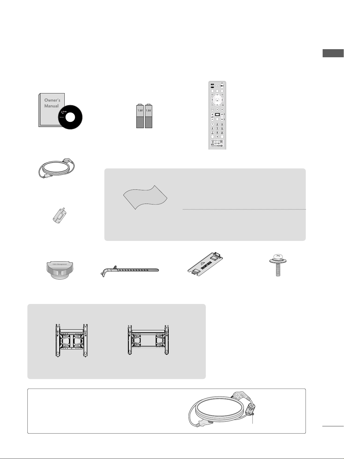
ACCESSORIES
Ensure that the following accessories are included with your TV. If an accessory is missing, please contact the
dealer where you purchased the product.
Owner’s Manual Batteries
Remote Control
Power Cord
Polishing Cloth
Polishing cloth for use on
the screen.
This item is not included for all models.
* Lightly wipe any stains or fingerprints on the
surface of the TV with the polishing cloth.
Do not use excessive force. This may cause
scratching or discolouration.
Cable management clip
(Refer to p.8)
A
Image shown may differ from your TV.
INPUT
TV/RAD
POWER
Q. MENU
MENU
Time Machine
RETURN
EXIT
OK
P
Q.VIEW
RATIO
REPEAT
AV MODE
P
A
G
E
LIST
❁❂✰❁❂✰
GUIDE
TIME
SHIFT
TIME
SHIFT
RECORD
STOP
LIVE
MARK
FAV
CHAR/NUM
DELETE
MUTE
ENERGY SAVING
Cable Holder
(Refer to p.8)
Ferrite Core
(This item is not included
for all models.)
Ferrite core can be used to reduce the electromagnetic
wave when connecting the power cord.
The closer the location of the ferrite core to the power
plug, the better it is.
Use of ferrite core
(This feature is not available for all models.)
Install the power plug closely.
x2
Protection cover
(Refer to p.9)
AW-50PG60MS
(Only 60PS8
***
)
AW-60PG60MS
Wall Mounting Bracket
(Separate purchase)
Bolts for stand assembly
(Refer to P. 6)
x 4

2
CONTENTS
CONTENTS
PREPARATION
Front Panel Controls..................................................... 4
Back Panel Information ................................................ 5
Stand installation .......................................................... 6
Careful installation advice ........................................... 7
Back Cover for Wire Arrangement..............................8
Swivel Stand......................................................................9
Not using the desk-type stand ...................................9
Desktop Pedestal Installation....................................10
Wall Mount: Horizontal installation .........................10
ANTENNA CONNECTION ........................................11
ACCESSORIES
. . . . . . . . . . . . . . . . . . . . . . . . . . . . . . . . . . . . . . . . . . . . .
1
DVR
Time MACHINE (Pause & Replay of Live TV)......56
RECORDING..................................................................59
SCHEDULE list ..............................................................63
Recording Quality.........................................................64
Time machine initialisation.........................................65
To use the internal hard disk.....................................66
USB...................................................................................67
Recorded list..................................................................70
Photo list.........................................................................73
Music list.........................................................................77
MOVIE list ......................................................................80
Divx Resgistration Code .............................................85
Deactivation...................................................................86
EPG (ELECTRONIC PROGRAMME
GUIDE)(IN DIGITAL MODE)
EPG (Electronic Programme Guide)
(in digital mode) ...........................................................53
Button Function in NOW/NEXT Guide Mode...54
Button Function in 8Day Guide Mode ................54
Button Function in Date Change Mode...............55
Button Function in Detailed Information Menu.55
Button Function in Schedule List Mode ..............55
Booster............................................................................39
Software Update...........................................................40
Diagnostics.....................................................................42
Selecting the programme table ................................43
Favourite programme setup.......................................44
Brief Information...........................................................45
Input List.........................................................................46
SIMPLINK........................................................................47
Input Label .....................................................................50
AV Mode .........................................................................51
Simple Manual ...............................................................51
Initialising (Reset to original factory settings)....52
EXTERNAL EQUIPMENT SETUP
Hd receiver setup..........................................................12
DVD SETUP....................................................................14
VCR SETUP.....................................................................16
AV output setup ...........................................................18
Other A/V Source Setup ............................................18
Digital audio out SETUP.............................................19
USB in setup .................................................................19
PC Setup.........................................................................20
Screen Setup for PC mode .....................................22
WATCHING TV / PROGRAMME CONTROL
REMOTE CONTROL KEY FUNCTIONS ................26
Turning on the TV ........................................................28
Programme Selection...................................................28
Volume Adjustment......................................................28
Quick Menu....................................................................29
On-Screen Menus Selection and adjustment.......30
Auto programme Tuning ............................................32
Manual programme Tuning
(In Digital Mode)..........................................................33
Manual programme Tuning
(In Analogue Mode) ....................................................34
Programme Edit ...........................................................36

3
CONTENTS
PICTURE CONTROL
Picture Size (Aspect Ratio) Control........................87
Picture Wizard...............................................................89
Energy Saving ...............................................................91
Preset picture settings
Picture Mode-Preset.................................................92
Manual Picture Adjustment
Picture Mode-User option ......................................93
Picture Improvement Technology ............................94
Expert Picture control .................................................95
Picture Reset..................................................................98
Image Sticking Minimization (ISM) Method.........99
Demo Mode.................................................................100
Mode Setting ...............................................................101
PARENTAL CONTROL / RATINGS
Set Password & Lock System
Setting up Your Password.......................................114
Lock System ...............................................................115
Set Password..............................................................116
Block Programme.........................................................117
Parental Guidance .......................................................118
Input Block....................................................................119
key Lock ........................................................................120
TELETEXT
Switch on/off ..............................................................121
SIMPLE Text..................................................................121
TOP Text........................................................................121
FASTEXT .......................................................................122
Special Teletext Functions........................................122
APPENDIX
Troubleshooting..........................................................123
Maintenance.................................................................125
Product Specifications ..............................................126
Programming the Remote control..........................127
IR Codes........................................................................128
External Control Through rs-232c ........................130
SOUND & LANGUAGE CONTROL
Auto volume leveller (auto volume) ......................102
Clear Voice II................................................................103
Preset Sound Settings (Sound mode)..................104
Sound Setting Adjustment - User Mode .............105
SRS TruSurround XT .................................................105
Balance..........................................................................106
TV Speakers On/Off Setup.....................................107
Selecting digital audio out.......................................108
Audio Reset..................................................................109
Stereo Reception (In Analogue Mode Only) ......110
Speaker Sound Output Selection...........................110
Language Selection (In digital mode only) ..........111
TIME SETTING
Clock Setup ..................................................................112
Auto On/Off Time Setting........................................113
Sleep Timer setting.....................................................113
4
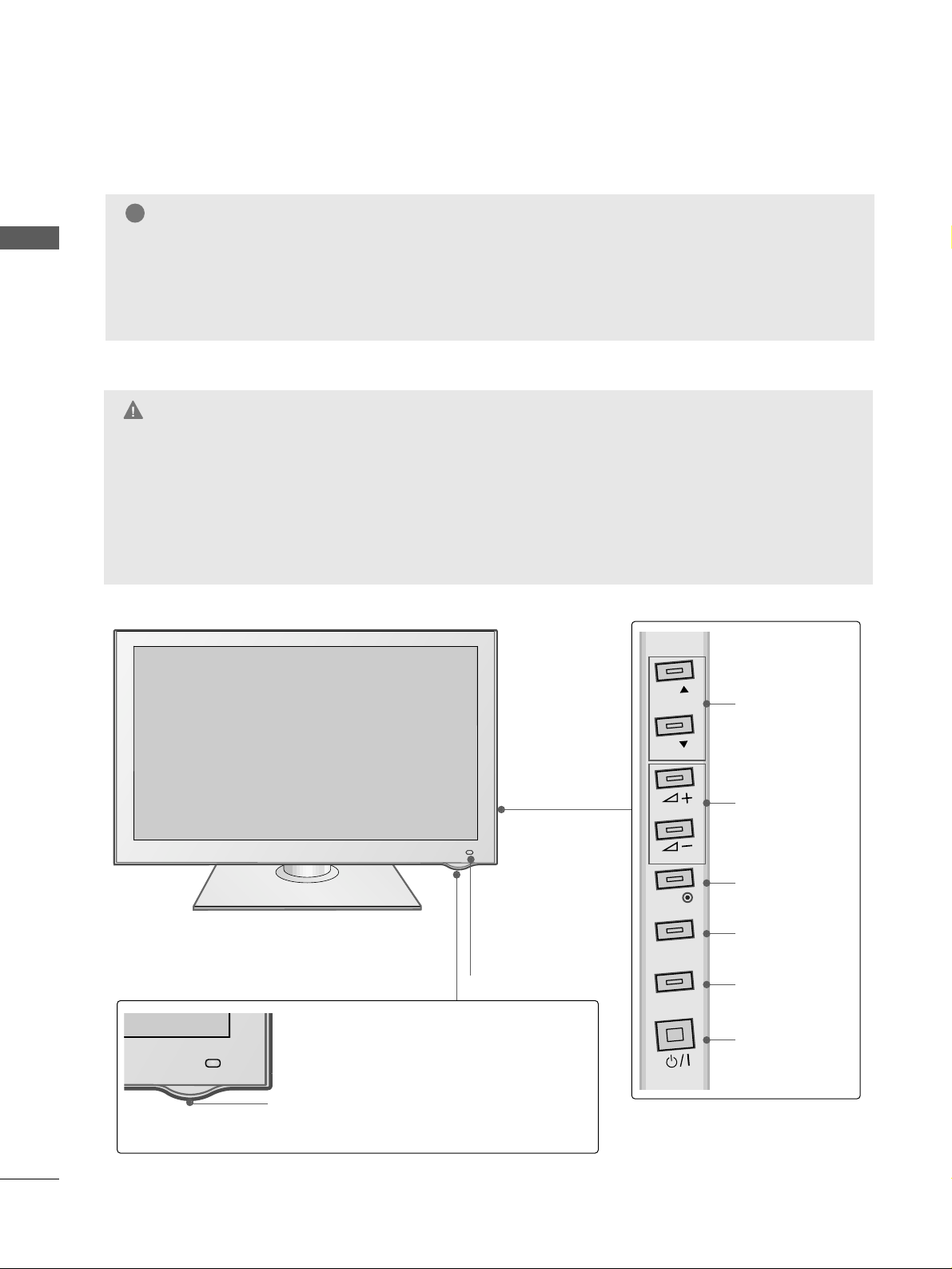
PREPARATION
PREPARATION
Power/Standby Indicator
• Illuminates red in standby mode.
•
The LED is off while the TV remains on.
PROGRAMME
VOLUME
OK
MENU
INPUT
POWER
IInn ttee lllliiggee nn tt SS eennssoorr
Adjusts picture according
to the surrounding conditions.
RReemmoo ttee CCoo nntt rrooll
SS eennssoorr
FRONT PANEL CONTROLS
■
Image shown may differ from your TV.
G
When the TV cannot be turned on with the remote control, press the main power button on the TV.
(When the power is turned off with the main power button on the TV, it will not be turned on with the
remote control).
G
Do not step on the glass stand or subject it to any impact.
It may break, causing possible injury from fragments of glass, or the TV may fall.
G
Do not drag the TV. The floor or the product may be damaged.
CAUTION
NOTE
!
G
TV can be placed in standby mode in order to reduce the power consumption. And the TV should be
switched off using the power switch on the TV if it will not be watched for some time, as this will reduce
energy consumption.
The energy consumed during use can be significantly reduced if the level of brightness of the picture is
reduced, and this will also reduce the overall running cost.
P
P
OK
MENU
INPUT
5
PREPARATION
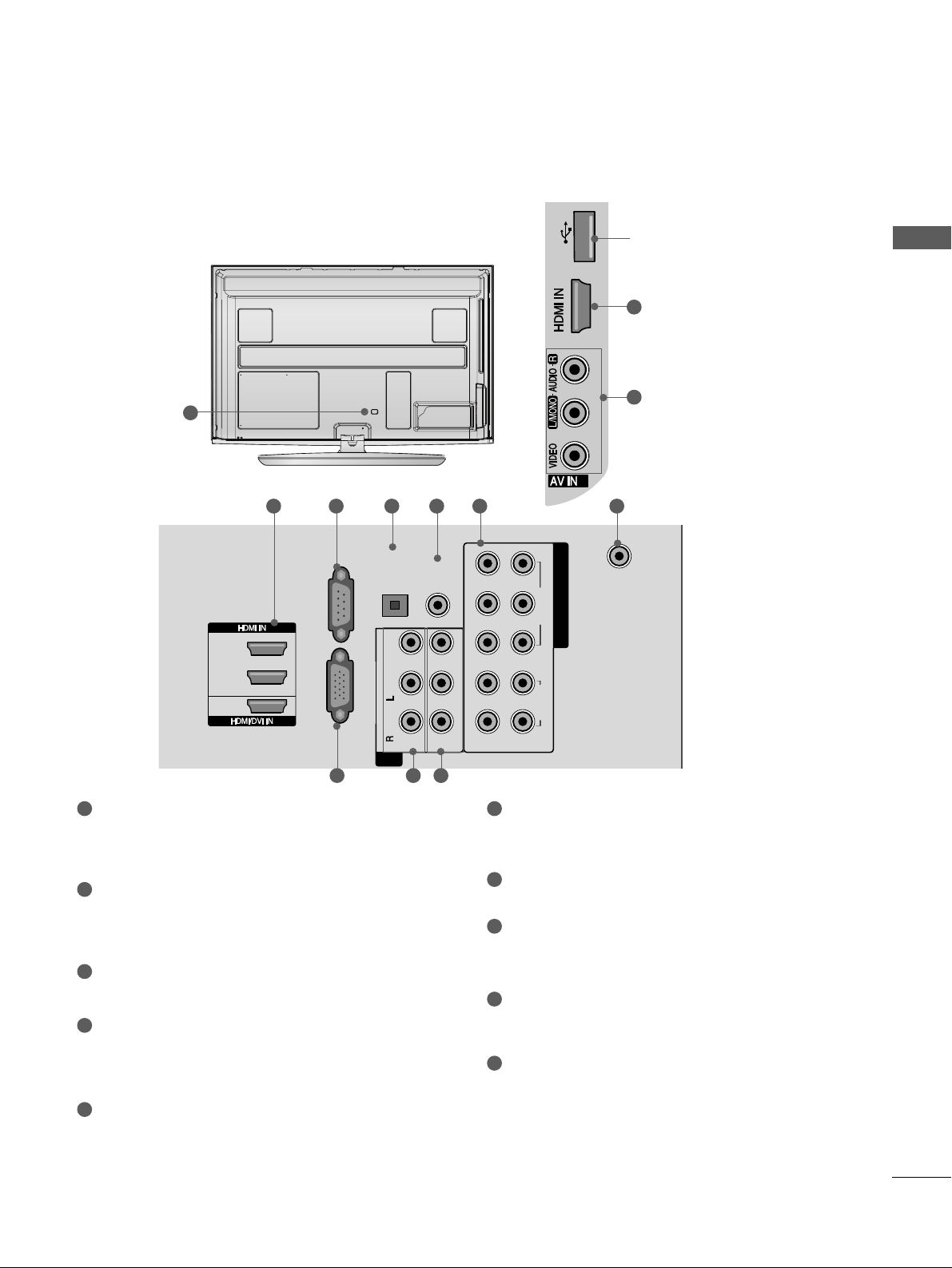
BACK PANEL INFORMATION
A
Image shown may differ from your TV.
ANTENNA
IN
AUDIO IN
(RGB/DVI)
OPTICAL
DIGITAL
AUDIO OUT
RL YP
B
P
R
VIDEO
VIDEO
AUDIO
OUT
IN1
R -AUDIO-LR -AUDIO-L VIDEOVIDEO
1
2
COMPONENT IN
AUDIO
(MONO)
-
-
2
USB IN
RGB IN(PC)
RS-232C IN
(CONTROL & SERVICE)
1
2
3
AV
2
4
USB IN USB IN
1
2 3 4 5 6 7
8 9
10
2
9
Power Cord Socket
This TV operates on an AC power. The voltage is
indicated on the Specifications page. Never
attempt to operate the TV on DC power.
HDMI Input
Connect an HDMI signal to HDMI IN.
Or DVI(VIDEO)signal to HDMI/DVI port with DVI
to HDMI cable.
RGB Input
Connect the output from a PC.
OPTICAL DIGITAL AUDIO OUT
Connect digital audio from various types of
equipment.
Note: In standby mode, these ports do not work.
RGB/DVI Audio Input
Connect the audio from a PC.
Component Input
Connect a component video/audio device to
these jacks.
Antenna Input
Connect RF antenna to this jack.
RS-232C Input
(CONTROL&SERVICE) Port
Connect to the RS-232C port on a PC.
This port is used for Service or Hotel mode.
Audio/Video Input (AV IN1/2)
Connect audio/video output from an external
device to these jacks.
AV Output
Connect second TV or monitor to the AV OUT
socket on the
TV.
1
7
6
8
9
10
2
3
4
5
USB IN
Used for viewing photos and
listening to MP3.
6
PREPARATION
PREPARATION
STAND INSTALLATION
■
Image shown may differ from your TV
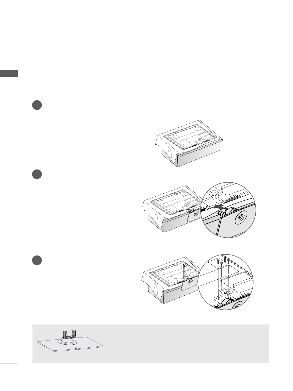
When assembling the desk type stand, check whether the bolt is fully tightened. (If not tightened fully, the
product can tilt forward after the product installation.) If you tighten the bolt with excessive force, the bolt
can deviate from abrasion of the tightening part of the bolt.
1
2
3
Carefully place the TV screen side down on a
cushioned surface to protect the screen from
damage.
Assemble the TV as shown.
Fix the 4 bolts securely using the holes in the
back of the TV.
When assembling the stand, make sure to distinguish and assemble the front
and rear side of the stand correctly.
Front
7
PREPARATION
CAREFUL INSTALLATION ADVICE
2
1
A
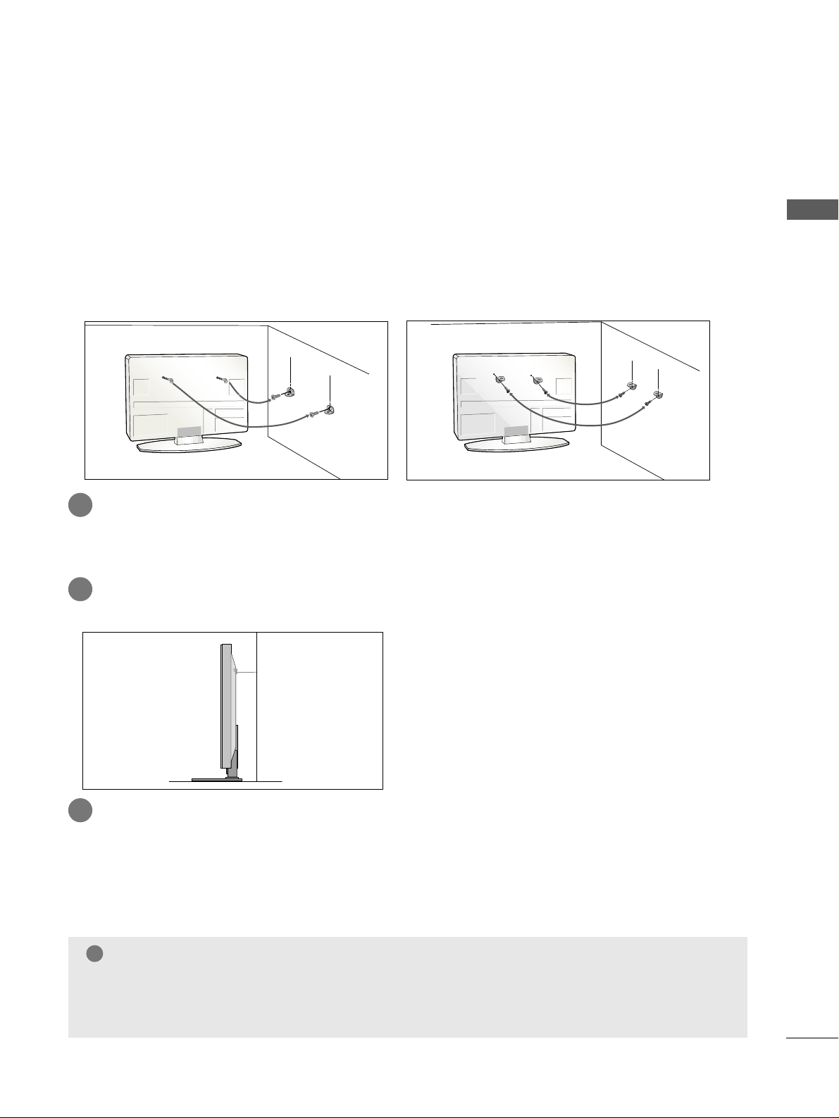
You should purchase necessary components to fix the TV safety and secure to the wall from the market.
A
Position the TV close to the wall to avoid the possibility of it falling when pushed.
A
The instructions shown below are a safer way to set up the TV, by fixing it to the wall, avoiding the possibility
of it falling forwards if pulled. This will prevent the TV from falling forward and causing injury. This will
also prevent the TV from damage. Ensure that children do not climb or hang from the TV.
NOTE
!
G
When moving the TV undo the cords first.
G
Use a platform or cabinet strong and large enough to support the size and weight of the TV.
G
To use the TV safely make sure that the height of the bracket on the wall and on the TV is the same.
2
3
1
1
2
Use the eye-bolts or TV brackets/bolts to fix the product to the wall as shown in the picture.
(If your TV has bolts in the eyebolts, loosen then bolts.)
* Insert the eye-bolts or TV brackets/bolts and tighten them securely in the upper holes.
Secure the wall brackets with the bolts on the wall. Match the height of the bracket that is mounted on the
wall.
3
Use a sturdy rope to tie the product for alignment. It is safer to tie the rope so it becomes horizontal between the wall and the product.
8
PREPARATION
PREPARATION
BACK COVER FOR WIRE ARRANGEMENT
■
Image shown may differ from your TV.
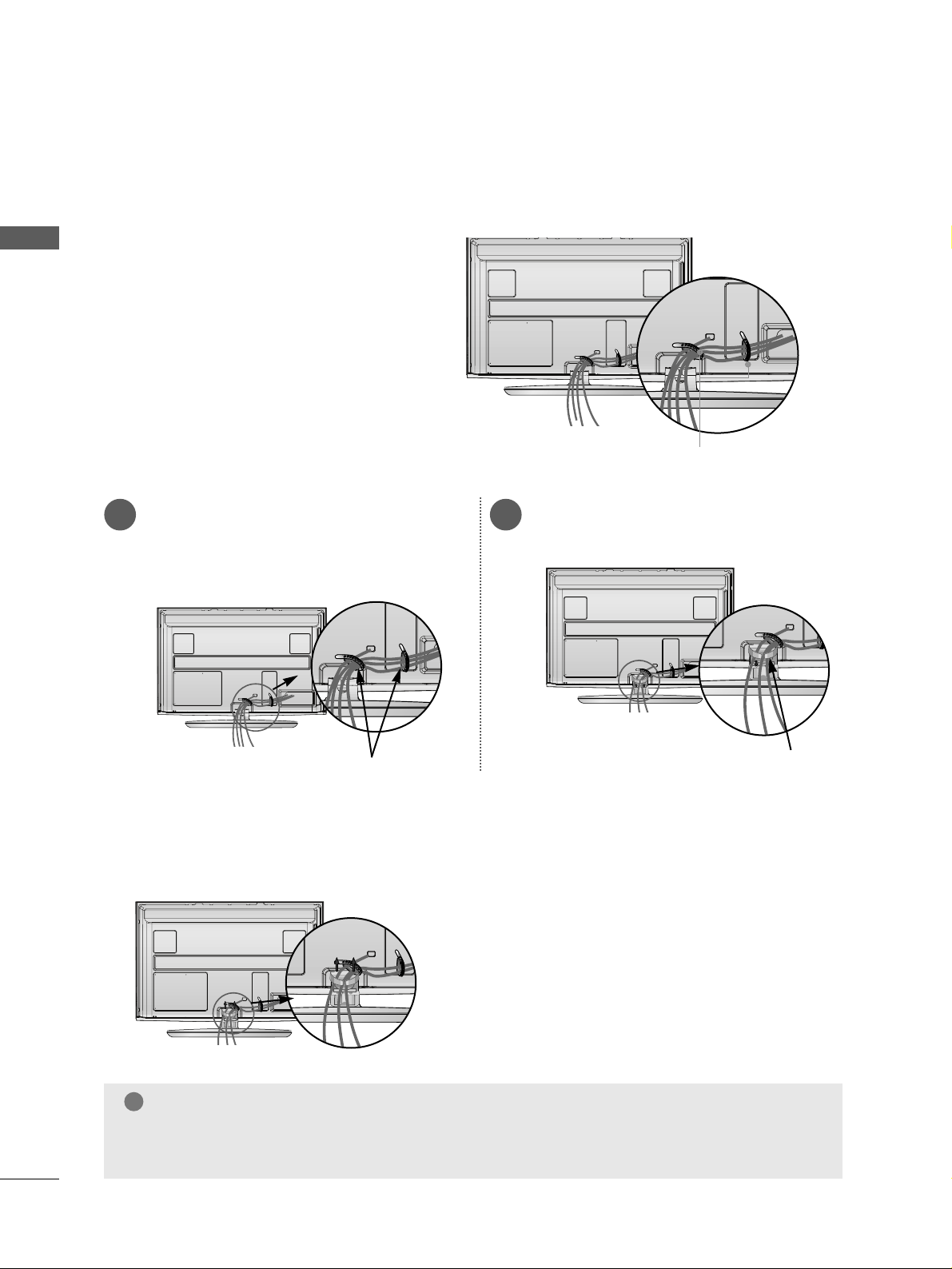
After Connecting the cables as necessary, install
CABLE HOLDER as shown and bundle the
cables.
CABLE HOLDER
After Connecting the cables as necessary, install
CABLE HOLDER as shown and bundle the cables.
To connect additional equipment, see the
EExxtteerrnnaall eeqquuiippmmeenn tt SS eettuupp
section.
1
Install the
CCAABBLLEE MMAANNAAGGEEMMEENNTT CCLLIIPP
as shown.
2
CABLE MANAGEMENT CLIP
CABLE HOLDER
NOTE
!
GG
Do not use the CABLE MANAGEMENT CLIP to lift the TV.
- If the TV is dropped, you may be injured or the TV may be damaged.
Hold the
CC AABBLL EE MMAANN AAGGEEMMEENN TT CCLLIIPP
with both hands and pull it upward.
How to remove the cable management clip
9
PREPARATION
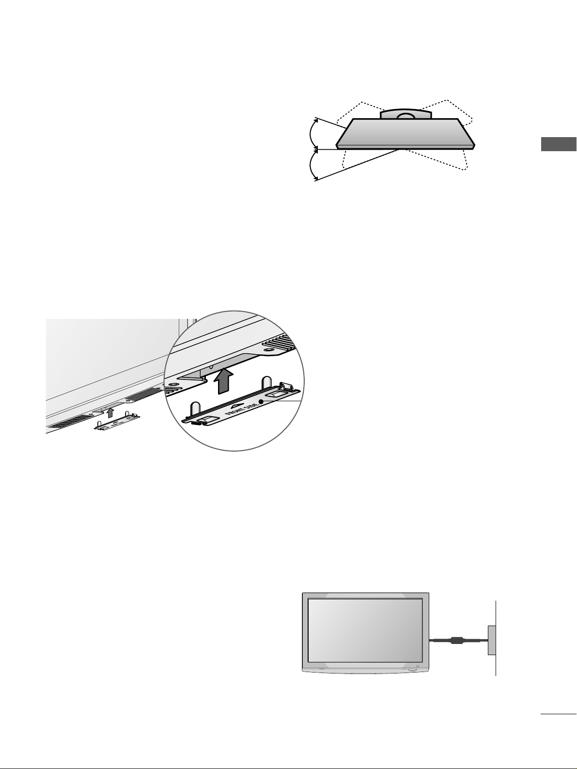
SWIVEL STAND
This feature is not available for all models.
After installing the TV, you can adjust the TV set manually to the left or right direction by 20 degrees to
suit your viewing position.
■
Here shown may differ from your TV.
When installing the wall-mounted unit, use the protection cover. Insert the
PPRROOTTEECCTTIIOONN CCOOVVEERR
into the TV
until clicking sound.
NOT USING THE DESK-TYPE STAND
Protection cover
Power Supply
Circuit breaker
EARTHING
Ensure that you connect the earth wire to prevent possible
electric shock. If grounding methods are not possible, have a
qualified electrician install a separate circuit breaker.
Do not try to earth the TV by connecting it to telephone
wires, lightening rods or gas pipes.
10
PREPARATION
PREPARATION
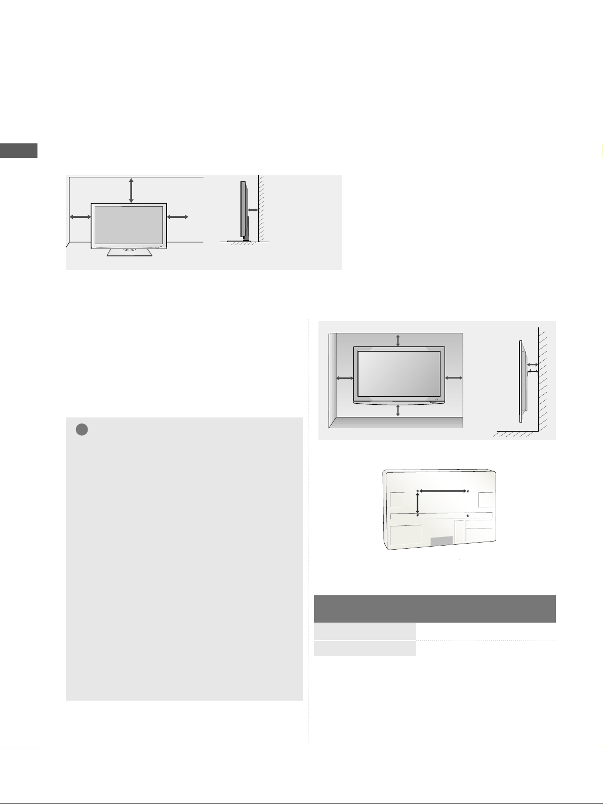
WALL MOUNT: HORIZONTAL INSTALLATION
A
We recommend the use of a LG Brand wall mounting
bracket when mounting the TV to a wall.
A
We recommend that you purchase a wall mounting
bracket which supports VESA standard.
A
LG recommends that wall mounting be performed
by a qualified professional installer.
4 inches 4 inches
4 inches
4 inches
4 inches
NOTE
!
G Should Install wall mount on a solid wall perpen-
dicular to the floor.
G Should use a special wall mount, if you want to
install it to ceiling or slanted wall.
G The surface that wall mount is to be mounted
on should be of sufficient strength to support
the weight of TV set; e.g. concrete, natural rock,
brick and hollow block.
G Installing screw type and length depends on the
wall mount used. Further information, refer to
the instructions included with the mount.
G LG is not liable for any accidents or damage to
property or TV due to incorrect installation:
- Where a non-compliant VESA wall mount is
used.
- Incorrect fastening of screws to surface which
may cause TV to fall and cause personal injury.
- Not following the recommended Installation
method.
4 inches 4 inches
4 inches
4 inches
DESKTOP PEDESTAL INSTALLATION
For adequate ventilation allow a clearance of 4” (10cm) all around the TV.
AA
BB
Model
VESA
(A *B)
Standard
Screw
Quantity
50PS8***
60PS8***
400 * 400
600 * 400
M6
M8
4
4
A
The TV can be installed in various ways such as on a wall, or on a desktop etc.
A
The TV is designed to be mounted horizontally.
11
PREPARATION
IN
R
ANTENNA
IN
R
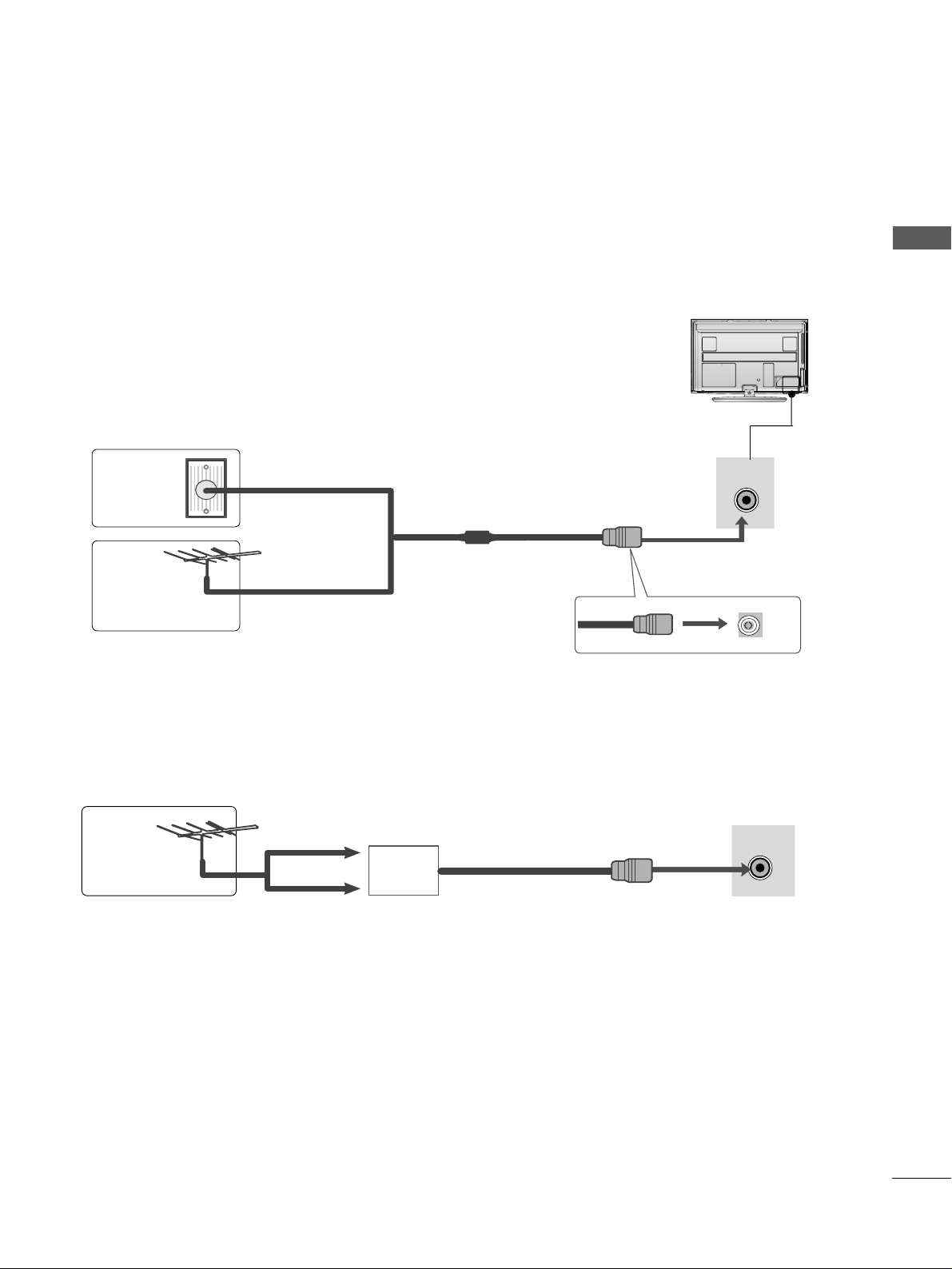
ANTENNA CONNECTION
■
For optimum picture quality, adjust antenna direction.
■
An antenna cable and converter are not supplied.
■
To prevent damage do not connect to the mains outlet until all connections are made between the devices.
Multi-family Dwellings/Apartments
(Connect to wall antenna socket)
Single-family Dwellings /Houses
(Connect to wall jack for outdoor antenna)
Outdoor
Antenna
(VHF, UHF)
Wall
Antenna
Socket
RF Coaxial Wire (75 ohm)
Antenna
UHF
Signal
Amplifier
VHF
■
In poor signal areas, to achieve better picture quality it may be necessary to install a signal amplifier to the
antenna as shown above.
■
If signal needs to be split for two TVs,use an antenna signal splitter for connection.
12
EXTERNAL EQUIPMENT SETUP
EXTERNAL EQUIPMENT SETUP
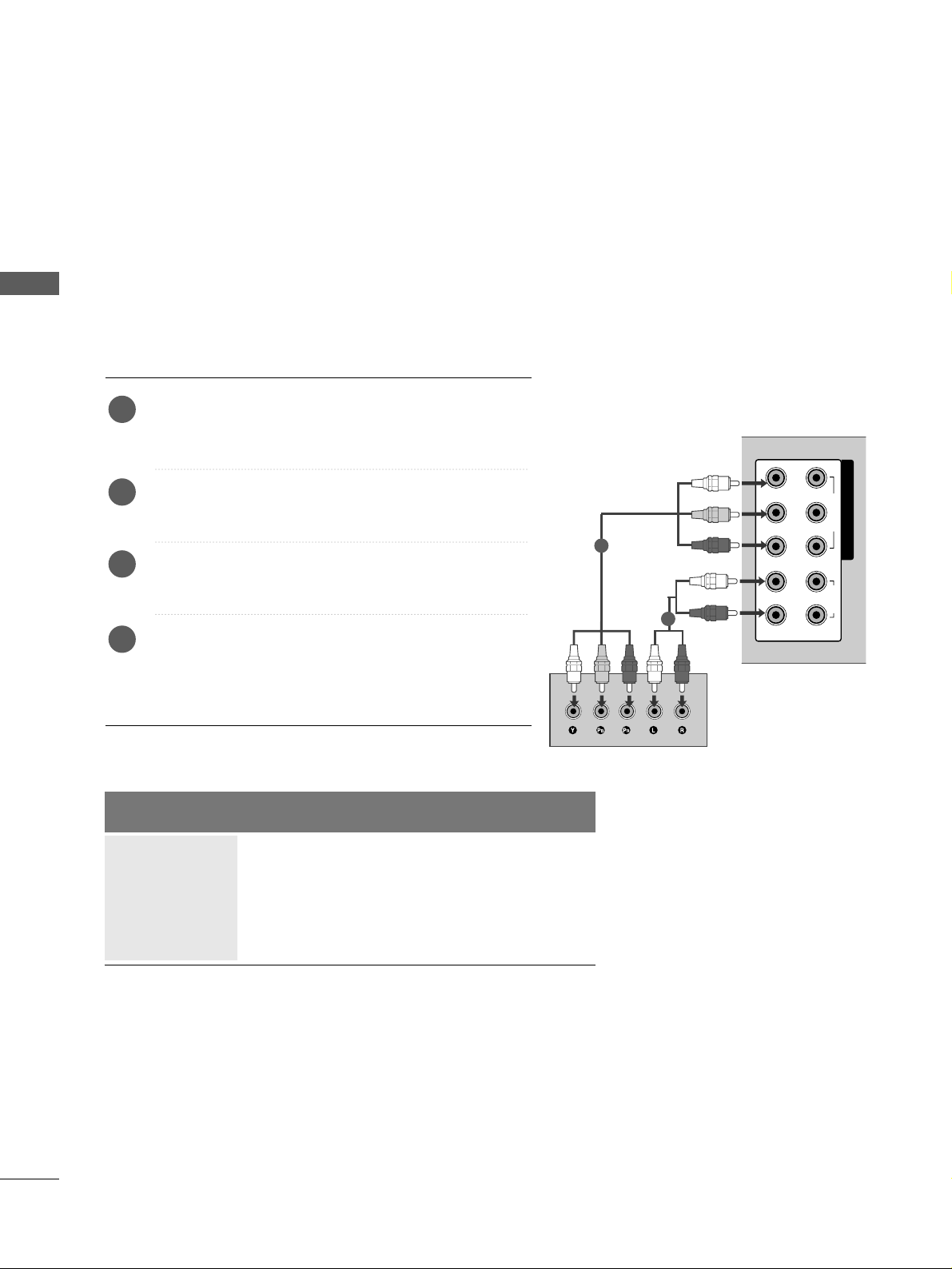
HD RECEIVER SETUP
■
To avoid damaging any equipment, never plug in any power cords until you have finished connecting all equipment.
■
Image shown may differ from your TV.
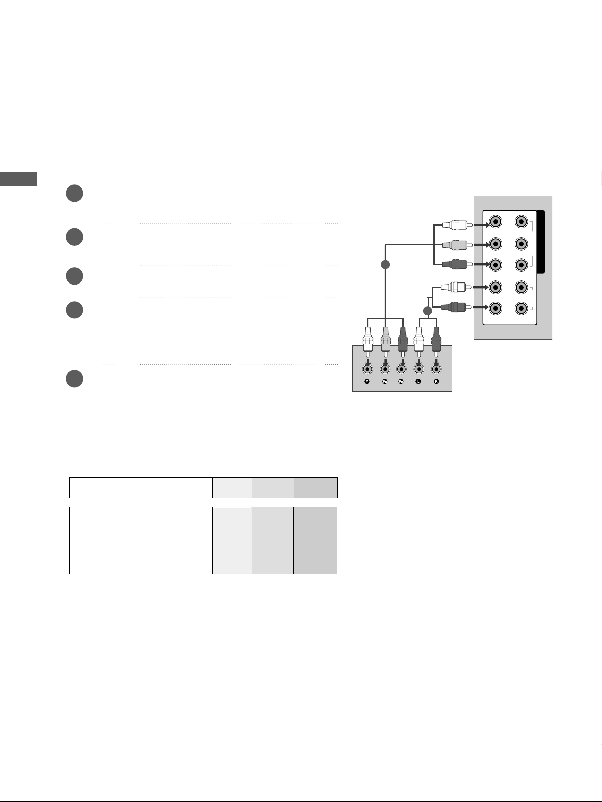
Connecting with a component cables
■
This TV can receive Digital RF/Cable signals without an external digital set-top box. However, if you do receive
Digital signals from a digital set-top box or other digital external device, refer to the diagram as shown below.
Connect the video outputs (Y, PB
, PR
)
of the digital set
top box to the
CC OO MMPPOONNEENN TT IINN VVIIDDEEOO
jacks on the
TV.
Connect the audio output of the digital set-top box to
the
CC OO MMPPOONNEENN TT IINN AA UU DD IIOO
jacks on the TV.
Turn on the digital set-top box.
(
Refer to the owner’s manual for the digital set-top box.
)
Select
CCoommpp oonn ee nntt 11
input source using the
II NN PPUUTT
button on the remote control.
If connected to
CCOOMMPPOONN EENNTT II NN 22
input, select
CCoommpp oonn ee nntt 22
input source.
2
3
4
1
Signal
480i/576i
480p/576p
720p/1080i
10 8 0 p
Component
O
O
O
O
(50/60Hz only)
HDMI
X
O
O
O
(24Hz/30Hz/50Hz/60Hz)
COMPONENT IN
12
VIDEO
AUDIO
RL YP
B
P
R
1
2
13
EXTERNAL EQUIPMENT SETUP
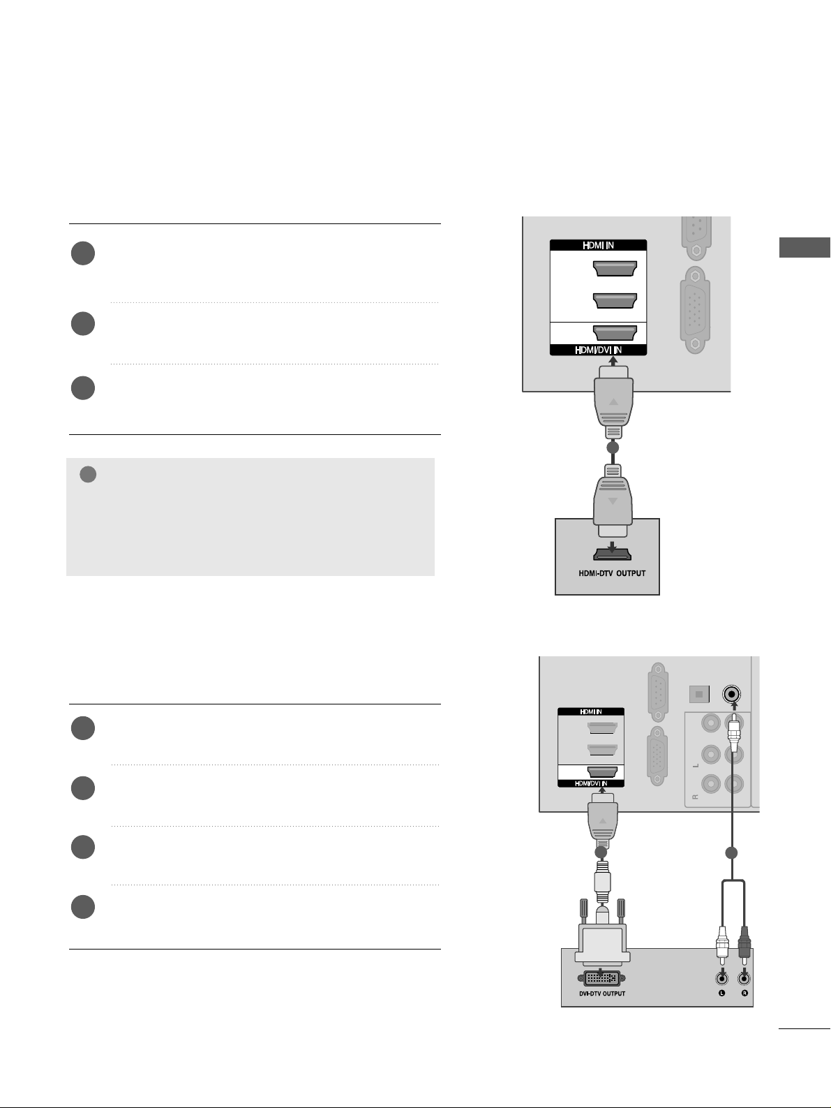
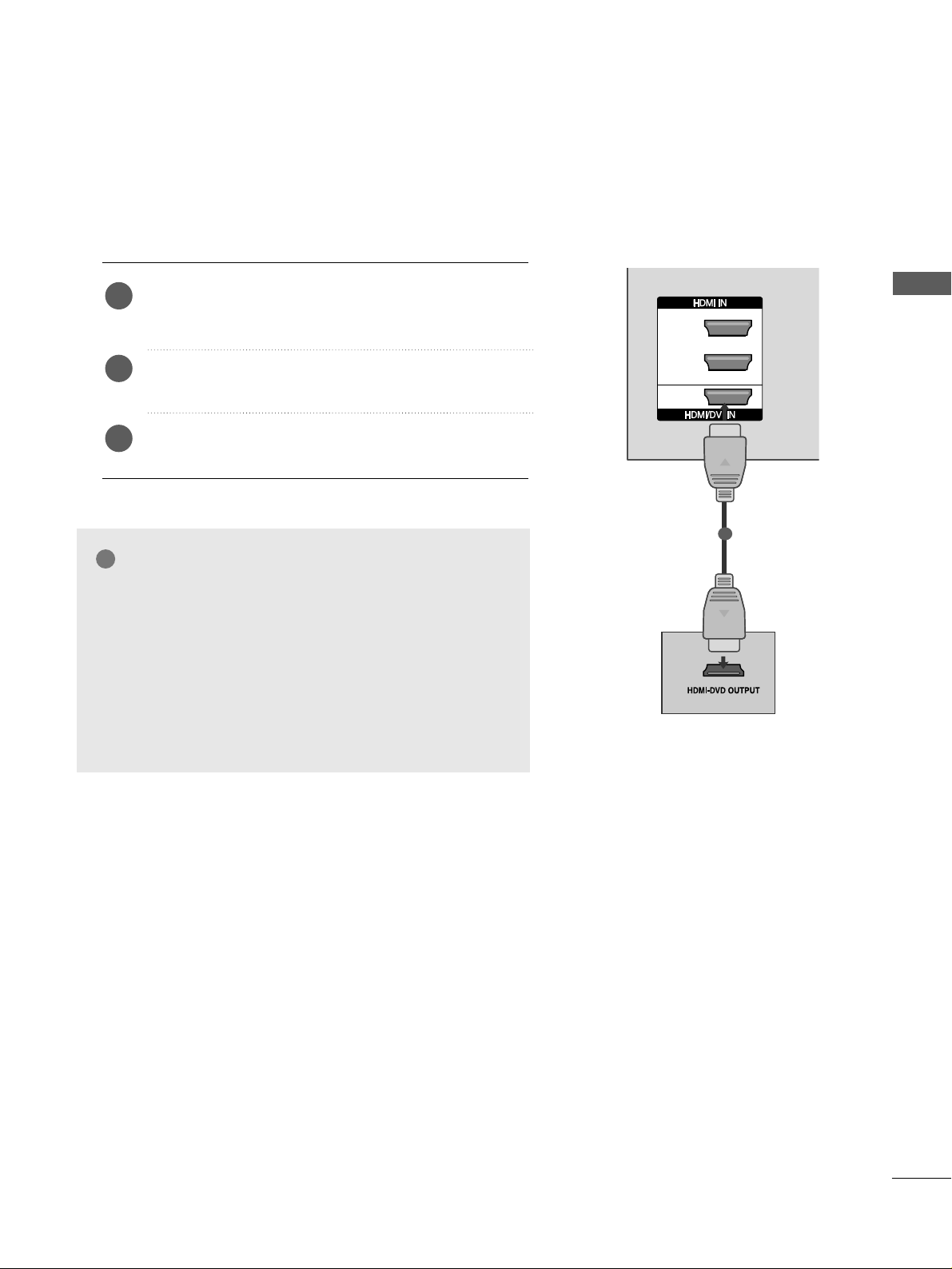
Connecting a set-top box with an HDMI cable
( )
RGB I
RS-232C IN
(CONTROL & SERVICE)
1
2
3
R -AUDIO-L VIDEO
1
Connecting with an HDMI to DVI cable
( )
AUDIO IN
(RGB/DVI)
OPTICAL
DIGITAL
AUDIO OUT
VIDEO
OUT
IN1
Mono
( )
AUDIO
-
-
RGB IN(PC)
RS-232C IN
(CONTROL & SERVICE)
1
2
3
R -AUDIO-L VIDEO
R -AUDIO-LR -AUDIO-L VIDEOVIDEO
1
2
Connect the digital set-top box to
HHDDMMII//DD VV II IINN 11
,
HHDDMMII II NN 22,HHDDMMII II NN 33
or
HHDDMMII II NN 44
jack on the
TV.
Turn on the digital set-top box.
(
Refer to the owner’s manual for the digital set-top box.
)
Select
HH DDMMII11, HH DDMMII22, HH DDMMII33
or
HH DDMMII44
input
source using the
II NN PPUUTT
button on the remote control.
2
3
1
Connect the digital set-top box to
HHDDMMII//DDVVII II NN 11
jack on the TV.
Connect the audio output of the digital set-top box to
the
AAUUDDIIOO IINN ((RRGGBB// DD VV II))
jack on the TV.
Turn on the digital set-top box. (Refer to the owner’s
manual for the digital set-top box.
)
Select
HH DDMMII11
input source using the
II NN PPUU TT
button
on the remote control.
2
3
4
1
NOTE
!
GG
Check that your HDMI cable is version 1.3 or higher.
If the HDMI cables don’t support HDMI version 1.3,
flickering or no screen display can result. Please use the
latest cables that support at least HDMI version 1.3.
14
EXTERNAL EQUIPMENT SETUP
EXTERNAL EQUIPMENT SETUP
DVD SETUP
Connecting with a component cables
COMPONENT IN
12
VIDEO
AUDIO
RL YP
B
P
R
Component Input ports
To achieve better picture quality, connect a DVD player to the component input ports as shown below.
Component ports on the TV
YPBP
R
Video output ports
on DVD player
Y
Y
Y
Y
PB
B-Y
Cb
Pb
P
R
R-Y
Cr
Pr
1
2
Connect the video outputs (Y, P B, P
R
)
of the DVD to the
CC OO MMPPOONNEENN TT IINN VVIIDD EEOO
jacks on the TV.
Connect the audio outputs of the DVD to the
CC OO MMPPOONNEENN TT IINN AA UU DD IIOO
jacks on the TV.
Turn on the DVD player, insert a DVD.
Select
CCoommpp oonn ee nntt 11
input source using the
II NN PPUU TT
button on the remote control.
If connected to
CCOOMMPPOONN EENNTT II NN 22
input, select
CCoommpp oonn ee nntt 22
input source.
Refer to the DVD player's manual for operating
instructions.
2
3
4
5
1
15
EXTERNAL EQUIPMENT SETUP
1
2
3
Connecting the HDMI cable
Connect the HDMI output of the DVD to the
HHDDMMII//DDVVII IINN 11,HHDDMMII IINN 22,HHDDMMII IINN 33
or
HHDD MMII
II NN 44
jack on the TV.
Select
HH DDMMII11, HH DDMMII22, HH DDMMII33
or
HH DDMMII44
input
source using the
II NN PPUUTT
button on the remote control.
Refer to the DVD player's manual for operating
instructions.
2
3
1
1
GG
The TV can receive video and audio signals simultaneously
when using a HDMI cable.
GG
If the DVD does not support Auto HDMI, you must set the
output resolution appropriately.
GG
Check that your HDMI cable is version 1.3 or higher.
If the HDMI cables don’t support HDMI version 1.3, flickering or no screen display can result. Please use the latest
cables that support at least HDMI version 1.3.
NOTE
!
16
EXTERNAL EQUIPMENT SETUP
EXTERNAL EQUIPMENT SETUP
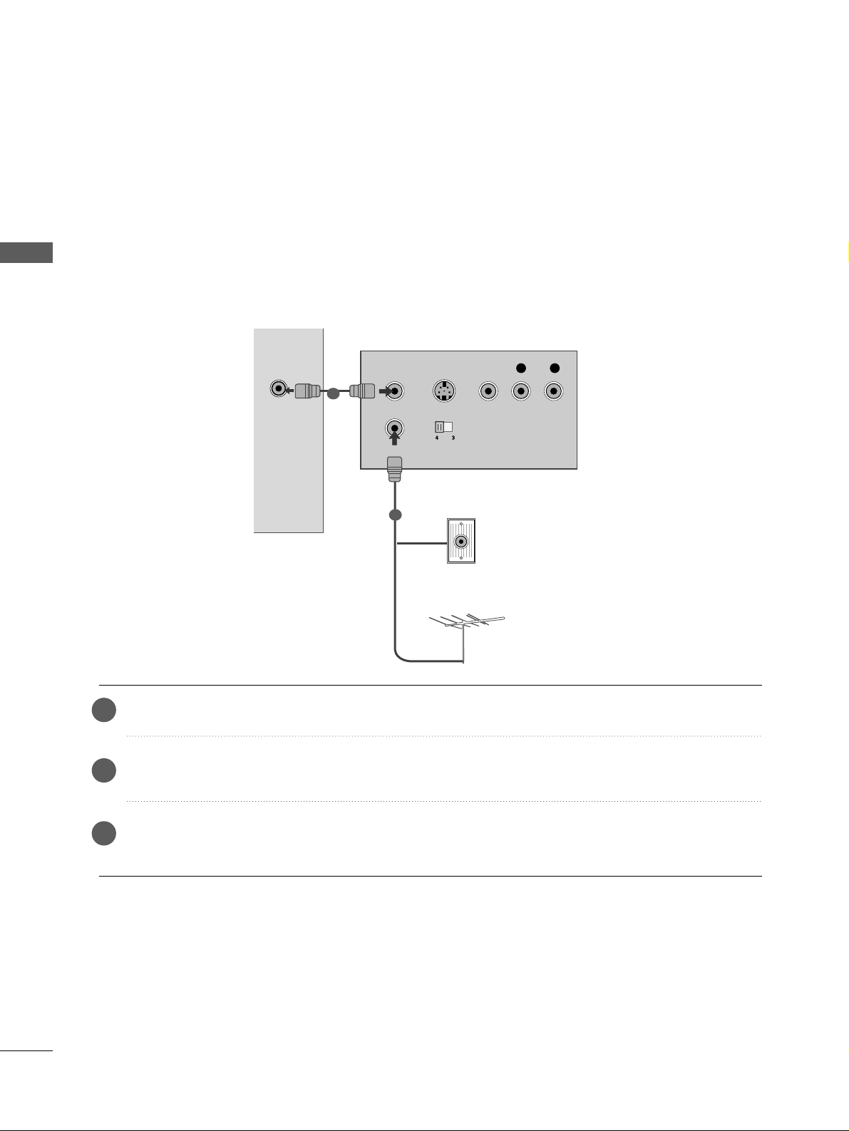
VCR SETUP
■
To avoid picture noise (interference), allow adequate distance between the VCR and TV.
ANTENNA
IN
OUTPUT
SWITCH
ANT IN
R
S-VIDEO VIDEO
ANT OUT
L
Wall Jack
Antenna
1
2
Connecting with a RF Cable
Connect the
AANNTT OO UU TT
socket of the VCR to the
AANN TT EENNNN AA II NN
socket on the TV.
Connect the antenna cable to the
AANNTT IINN
socket of the VCR.
Press the
PPLLAAYY
button on the VCR and match the appropriate channel between the TV and VCR for
viewing.
2
3
1
17
EXTERNAL EQUIPMENT SETUP
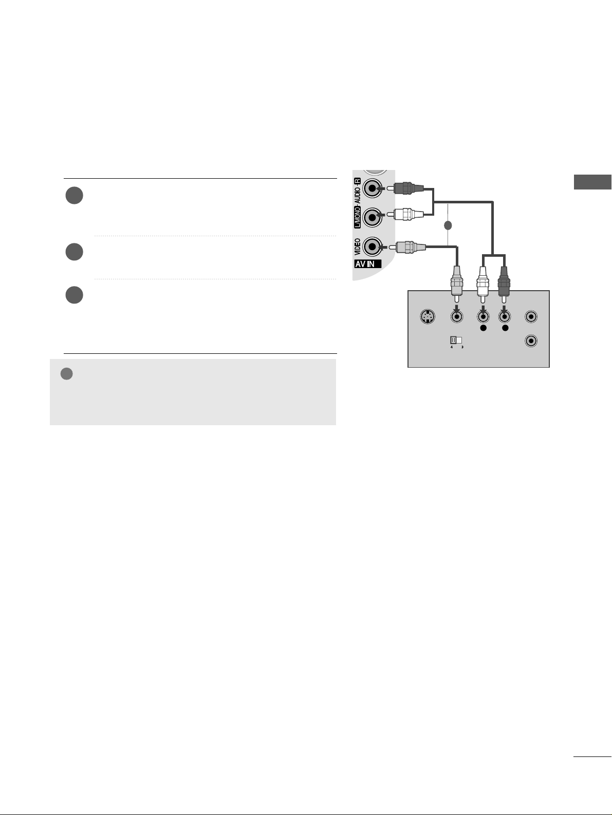
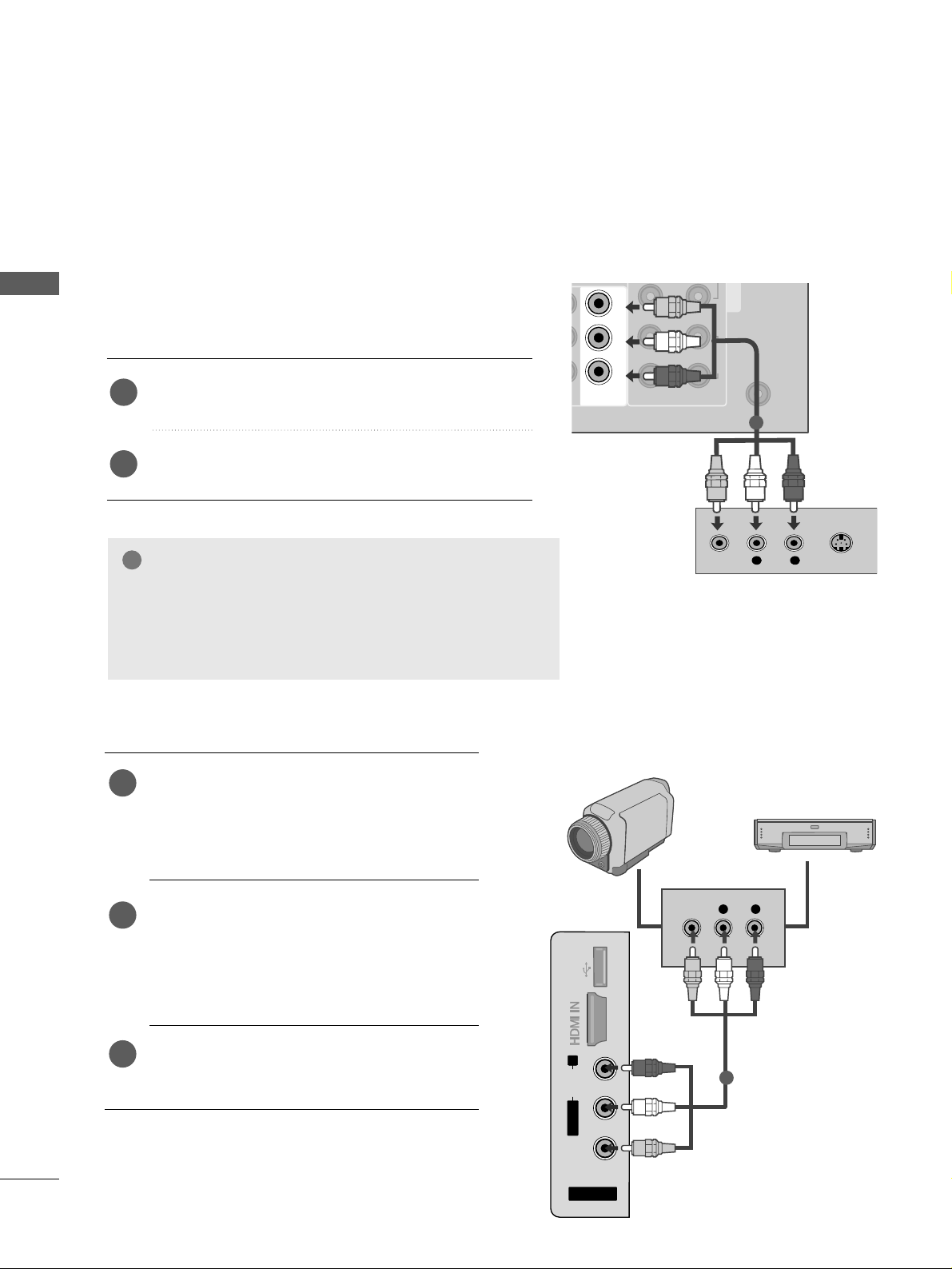
Connecting with an RCA cable
L
R
S-VIDEO
VIDEO
OUTPUT
SWITCH
ANT IN
ANT OUT
2
2
Connect the
AAUUDD IIOO/VVII DD EEOO
jacks between TV and
VCR. Match the jack colours (Video = yellow, Audio Left
= white, and Audio Right = red)
Insert a video tape into the VCR and press PLAY on
the VCR. (Refer to the VCR owner’s manual.
)
Select
AA VV22
input source using the
II NN PPUUTT
button on
the remote control.
If connected to
AAVV II NN 11
input, select
AA VV11
input
source.
1
2
3
G
If you have a mono VCR, connect the audio cable from the
VCR to the
AAUUDDII OO LL // MMOONN OO
jack of the TV.
NOTE
!
1
18
EXTERNAL EQUIPMENT SETUP
EXTERNAL EQUIPMENT SETUP
AV OUTPUT SETUP (
Only Analogue Mode
)
The TV has a special signal output capability which allows you
to hook up the second TV or monitor.
Connect the second TV or monitor to the TV’s
AAVV OOUUTT
jacks.
See the Operating Manual of the second TV or monitor
for further details regarding that device’s input settings.
G
Only Analog Channel and AV can be used for AV out.
Component, RGB, HDMI input sources cannot be used for
AV out.
G
We recommend to use the AV OUT jacks for VCR recording.
NOTE
!
2
1
ANTENNA
IN
CO
1
2
AUDIO
OUT
L R
S-VIDEO
VIDEO
RL P
R
R -AUDIO-LR -AUDIO-L
VIDEO
1
OTHER A/V SOURCE SETUP
Connect the
AAUUDDII OO/VVII DD EEOO
jacks between TV
and external equipment. Match the jack colours
.
(
Video = yellow, Audio Left = white, and Audio Right
= red
)
Select
AAVV22
input source using the
II NN PPUU TT
button
on the remote control.
If connected to
AAVV IINN11
, select
AAVV11
input
source.
Operate the corresponding external equipment.
Refer to external equipment operating guide.
1
2
3
AV IN 2
L/ MONO
R
AUDIO
VIDEO
USB IN
L R
VIDEO
4
Camcorder
Video Game Set
1
19
EXTERNAL EQUIPMENT SETUP
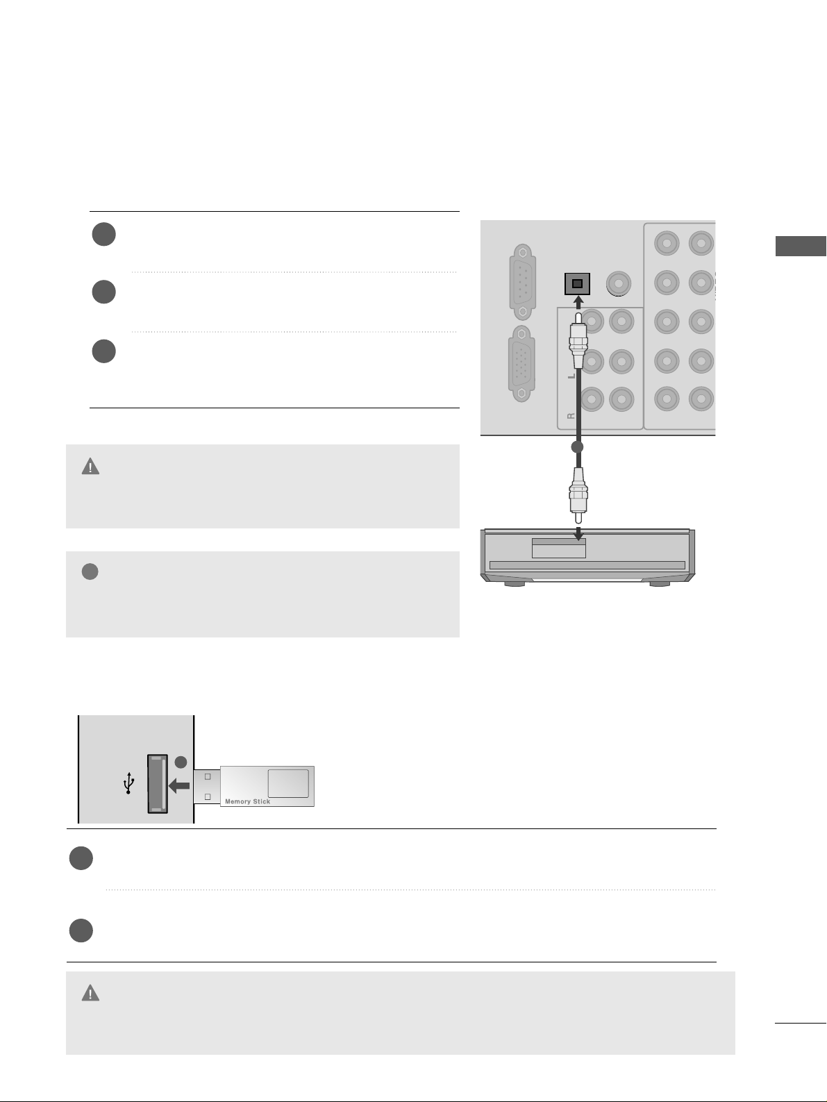
DIGITAL AUDIO OUT SETUP
Sending the TV’s audio signal to external audio equipment via the Digital Audio Output (Optical) port.
If you want to enjoy digital broadcasting through 5.1-channel speakers, connect the OPTICAL DIGITAL
AUDIO OUT terminal on the back of TV to a DVD Home Theatre (or amp).
G
Do not look into the optical output port. Looking at the
laser beam may damage your vision.
CAUTION
OPTICAL
DIGITAL
AUDIO OUT
AUDIO IN
(RGB/DVI)
RL YP
B
P
R
VIDEO
VIDEO
OUT
IN1
1
2
Mono
( )
AUDIO
-
-
RGB IN(PC)
RS-232C IN
(CONTROL & SERVICE)
R -AUDIO-LR -AUDIO-L
VIDEO
Connect one end of an optical cable to the TV Digital
Audio (Optical)Output port.
Connect the other end of the optical cable to the
digital audio (optical)input on the audio equipment.
Set the “TV Speaker option - Off ” in the AUDIO
menu.(
G
pp.. 110066
). Refer to the external audio equipment
instruction manual for operation.
2
3
1
1
G
When connecting with external audio equipments, such as
amplifiers or speakers, please turn the TV speakers off.
NOTE
!
USB IN SETUP
■
Here shown may differ from your TV.
USB IN
Connect the USB device to the
UUSSBB IINN
jacks on the side of TV.
After connecting the
UUSSBB IINN
jacks, you can use the
UU SSBB
function. (
GG
pp..6677
)
2
1
1
G
Before removing the USB device, please use the Remove USB Device in Quick Menu to prevent software,
data loss or damage to USB HDD.
CAUTION
20
EXTERNAL EQUIPMENT SETUP
EXTERNAL EQUIPMENT SETUP
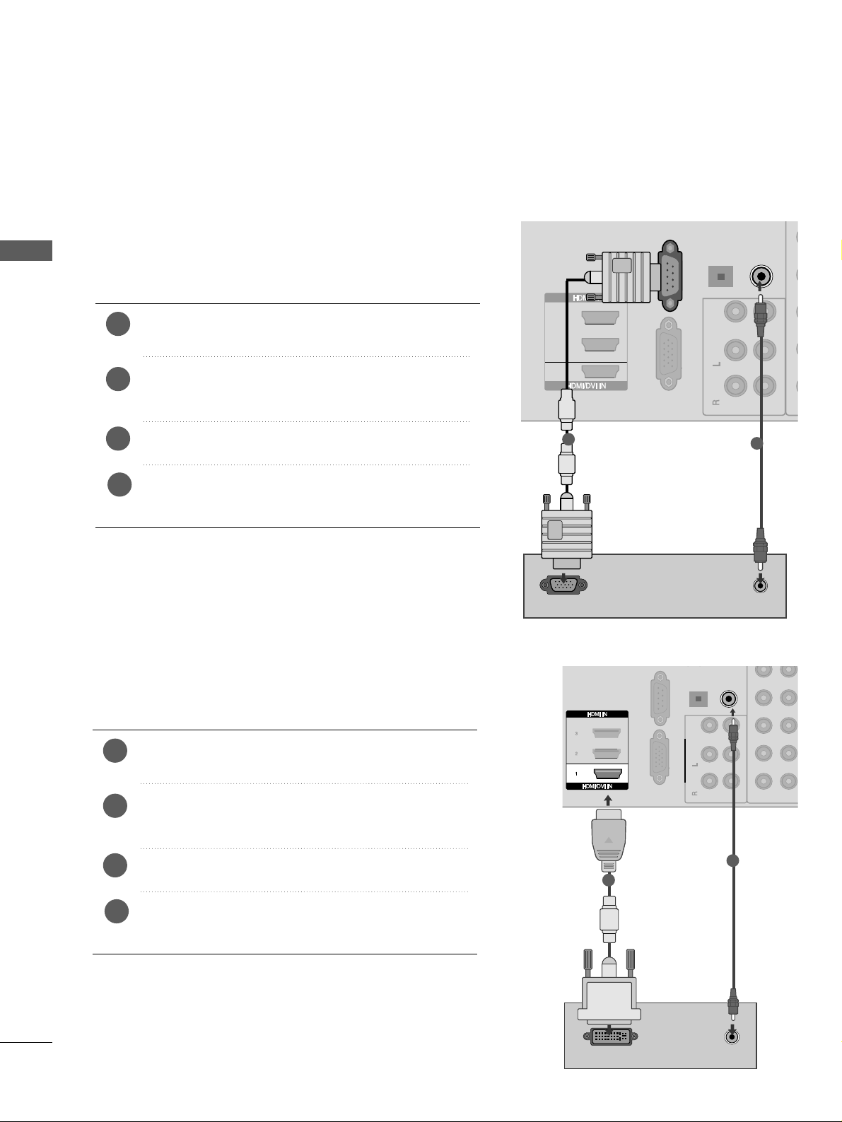
PC SETUP
This TV provides Plug and Play capability, meaning that the PC adjusts automatically to the TV's settings.
Connecting with a D-sub 15 pin cable
AUDIO IN
(RGB/DVI)
OPTICAL
DIGITAL
AUDIO OUT
VIDEO
OUT
IN1
R -AUDIO-LR -AUDIO-L VIDEOVIDEO
Mono
( )
AUDIO
-
-
RGB IN(PC)
1
2
3
AUDIO
RGB OUTPUT
RS-232C IN
(CONTROL & SERVICE)
1
2
4
Connect the RGB output of the PC to the
RRGGBB II NN
((PPCC))
jack on the TV.
Connect the PC audio output to the
AAUUDDIIOO II NN
((RRGGBB//DDVVII))
jack on the TV.
Turn on the PC and the TV
Select
RR GG BB
input source using the INPUT button on
the remote control.
2
3
1
R -AUDIO-L VIDEO
( )
DVI-PC OUTPUT
AUDIO
RGB IN(PC)
RS-232C IN
(CONTROL & SERVICE)
AUDIO IN
(RGB/DVI)
OPTICAL
DIGITAL
AUDIO OUT
RL P
B
P
R
VIDEO
OUT
IN1
R -AUDIO-LR -AUDIO-L VIDEOVIDEO
1
2
Mono
( )
AUDIO
-
-
Connecting with a HDMI to DVI cable
1
2
4
Connect the DVI output of the PC to the
HHDDMMII // DD VVII
II NN 11
jack on the TV.
Connect the PC audio output to the
AAUUDDIIOO II NN
((RRGGBB//DDVVII))
jack on the TV.
Turn on the PC and the TV.
Select
HH DDMMII 11
input source using the INPUT button
on the remote control.
2
3
1
21
EXTERNAL EQUIPMENT SETUP
Supported Display Resolution
RGB-PC, HDMI/DVI-PC mode
Resolution
Horizontal
Frequency(kHz)
Vertical
Frequency(Hz)
HDMI/DVI-DTV mode
59.94
60
59.94
60
50.00
50.00
59.94
60
50.00
59.94
60
24.00
30
50.00
59.94
60
31.649
31.469
31.47
31.50
31.25
37. 50
44.96
45.00
28.125
33.72
33.75
27.00
33.75
56.25
67. 433
67. 50
Resolution
Horizontal
Frequency(kHz)
Vertical
Frequency(Hz)
640x480
720x480
720x576
1280x720
1920x1080
70.08
59.94
60.31
60.00
59.87
60.015
60.02
59.979
59.934
31.468
31.469
37. 879
48.363
47. 776
47. 712
63.98
65.317
66.587
720x400
640x480
800x600
1024x768
1280x768
1360x768
1280x1024
1400x1050
1920x1080
NOTE
!
G
Avoid keeping a fixed image on the set’s screen
for prolonged periods of time. The fixed image
may become permanently imprinted on the
screen; use a screen saver when possible.
G
There may be interference relating to resolution,
vertical pattern, contrast or brightness in PC
mode. Change the PC mode to another resolution
or change the refresh rate to another rate or
adjust the brightness and contrast on the menu
until the picture is clear.
If the refresh rate of the PC graphic card can not
be changed, change the PC graphic card or consult the manufacturer of the PC graphic card.
G
The synchronization input waveform for
Horizontal and Vertical frequencies are separate.
G
We recommend using 1920x1080, 60Hz
(50PS8
***/60PS8***
) for the PC mode, they pro-
vide the best picture quality.
G
Connect the signal cable from the monitor output
port of the PC to the RGB (PC) port of the TV or the
signal cable from the HDMI output port of the PC to
the HDMI IN (or HDMI/DVI IN) port on the TV.
G
Connect the audio cable from the PC to the
Audio input on the TV. (Audio cables are not
included with the TV).
G
If using a sound card, adjust PC sound as
required.
G
If required, adjust the settings for Plug and Play
functionality
G
If the graphic card on the PC does not output
analogue and digital RGB simultaneously, connect
only one of either RGB or HDMI IN (or HDMI/DVI
IN) to display the PC output on the TV.
G
If graphic card on the PC does output analogue
and digital RGB simultaneously, set the TV to
either RGB or HDMI; (the other mode is set to
Plug and Play automatically by the TV.)
G
DOS mode may not work depending on the video
card if you use a HDMI to DVI cable.
G
If you use too long an RGB-PC cable, there may
be interference on the screen. We recommend
using under 5m of cable. This provides the best
picture quality.
22
EXTERNAL EQUIPMENT SETUP
EXTERNAL EQUIPMENT SETUP
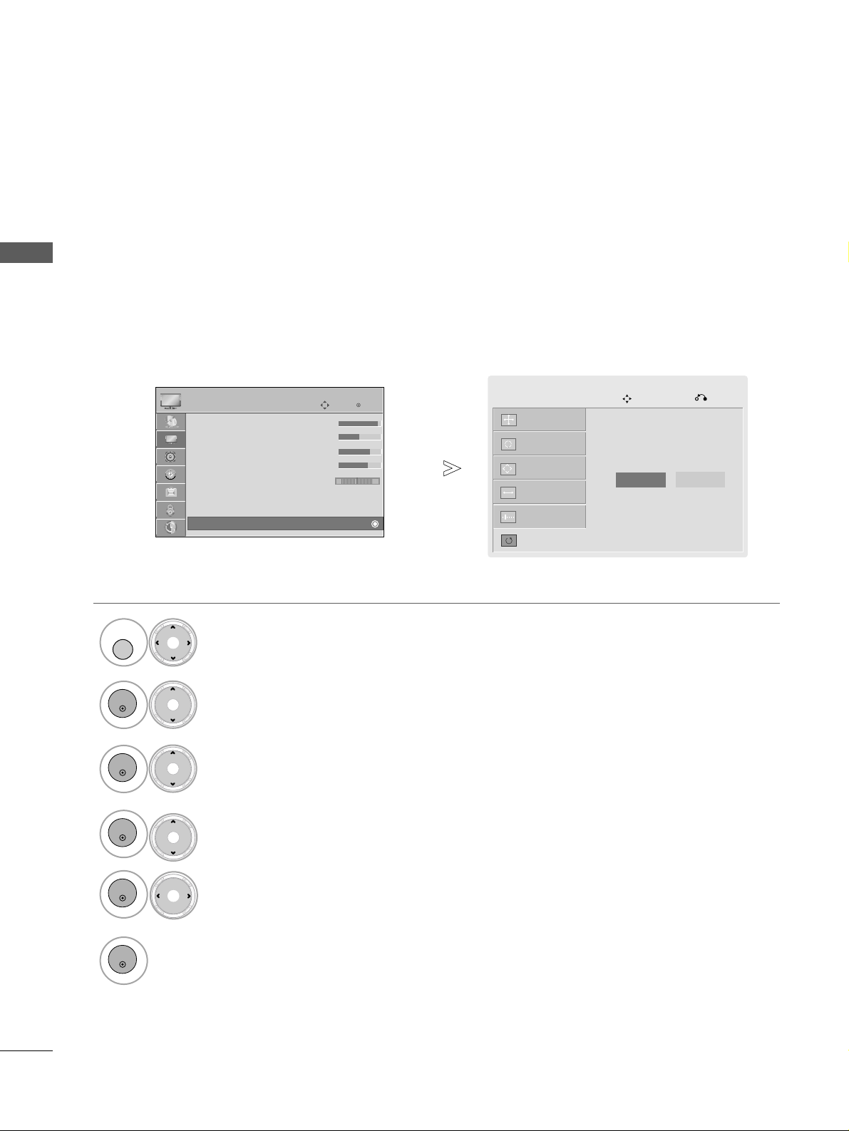
Screen Setup for PC mode
Returns Position, Size and Phase to the factory default settings.
This function works in the following mode : RGB[PC].
Screen Reset
• Press the
MMEENNUU
button to return to normal TV viewing.
• Press the
RR EETTUURR NN
button to move to the previous menu screen.
Run
RReesseett
.
OK
Move
PICTURE
E
RG
• Contrast 100
• Brightness 50
• Sharpness 70
• Colour 70
• Tint 0
• Advanced Control
• Picture Reset
Screen
Select
PPIICCTT UURREE
.
Select
SSccrr eeeenn
.
Select
RReesseett
.
Select
YY ee ss
.
2
OK
4
3
OK
OK
5
OK
6
OK
Select
TTVV SSEETT UUPP
.
1
MENU
To Set
Auto Config.
SCREEN
Move
Previous
Resolution
Position
Size
Phase
Reset
Yes
No
23
EXTERNAL EQUIPMENT SETUP
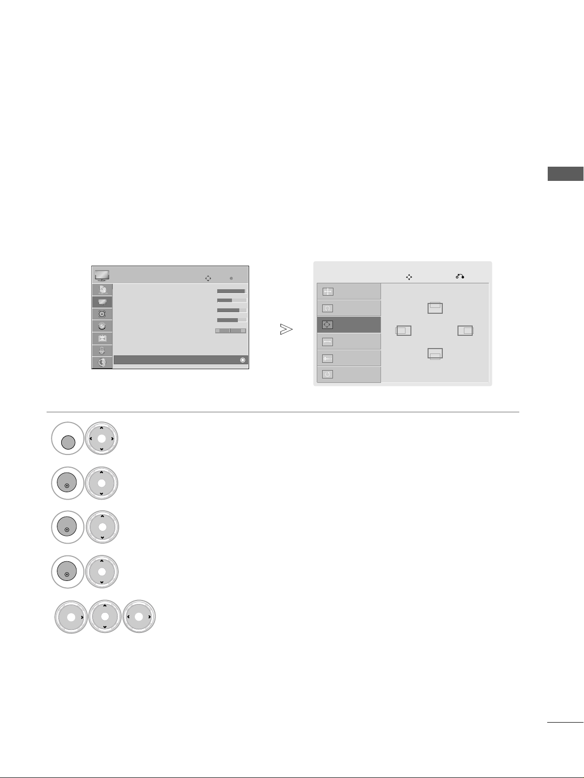
If the picture is not clear after auto adjustment and especially if characters are still trembling, adjust the
picture phase manually.
This function works in the following mode : RGB[PC].
Adjustment for screen Position, Size, Phase
Select
PPIICCTT UURREE
.
Select
SSCCRREEEE NN
.
Select
PPoossiitt ii oonn, SSiizzee
or
PPhhaassee
.
Make appropriate adjustments.
2
OK
Select
TTVV SSEETT UUPP
.
1
MENU
4
5
3
OK
OK
• Press the
MMEENNUU
button to return to normal TV viewing.
• Press the
RR EETTUU RRNN
button to move to the previous menu screen.
Auto Config.
SCREEN
Move
Previous
Resolution
Position
G
Size
Phase
Reset
GF
D
E
OK
Move
PICTURE
E
RG
• Contrast 100
• Brightness 50
• Sharpness 70
• Colour 70
• Tint 0
• Advanced Control
• Picture Reset
Screen
24
EXTERNAL EQUIPMENT SETUP
EXTERNAL EQUIPMENT SETUP
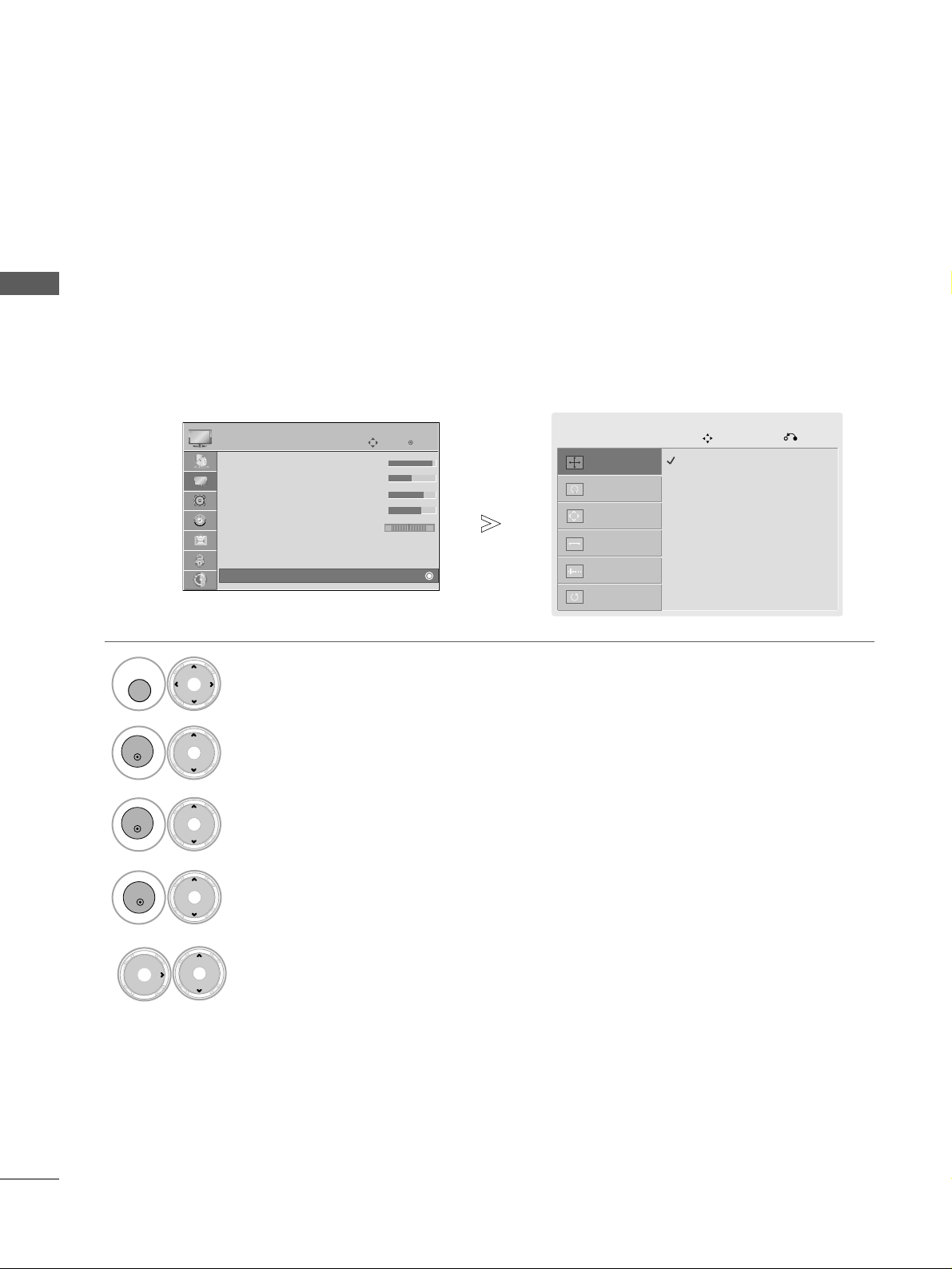
To view a normal picture, match the resolution of RGB mode and selection of PC mode.
This function works in the following mode: RGB[PC]
Selecting Resolution
Select
PPIICCTT UURREE
.
Select
SSCCRREEEE NN
.
Select
RReess oolluuttii oonn
.
Select the desired resolution.
2
OK
Select
TTVV SSEETT UUPP
.
1
MENU
4
5
3
OK
OK
• Press the
MMEENNUU
button to return to normal TV viewing.
• Press the
RR EETTUU RRNN
button to move to the previous menu screen.
Auto Config.
SCREEN
Move
Previous
Resolution
G
Position
Size
Phase
Reset
1024 x 768
1280 x 768
1360 x 768
OK
Move
PICTURE
E
RG
• Contrast 100
• Brightness 50
• Sharpness 70
• Colour 70
• Tint 0
• Advanced Control
• Picture Reset
Screen
25
EXTERNAL EQUIPMENT SETUP
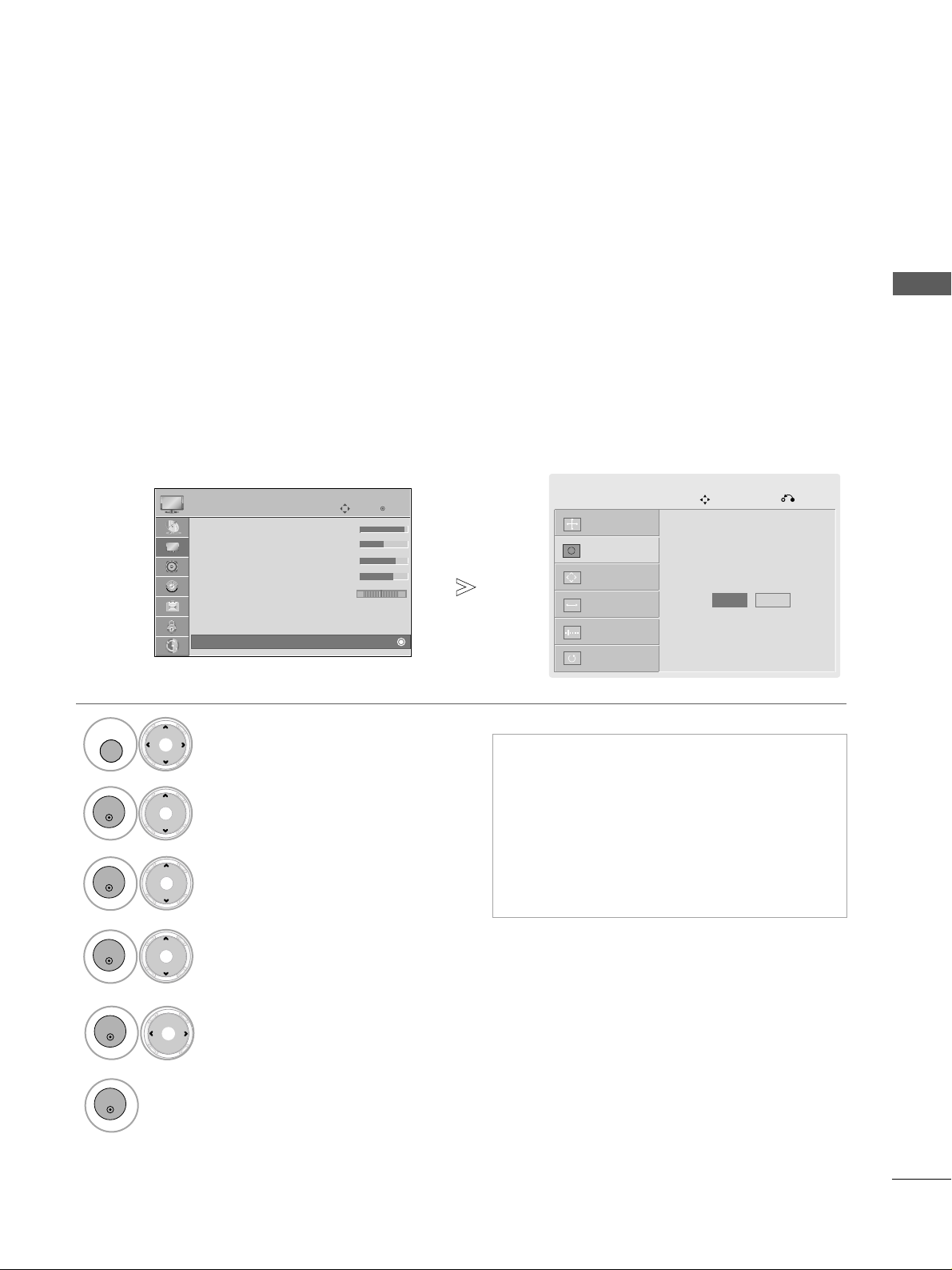
Automatically adjusts picture position and minimizes image instability. After adjustment, if the image is still
not correct, your TV is functioning properly but needs further adjustment.
AAuuttoo ccoo nnff iigguurree
This function is for automatic adjustment of the screen position, size, and phase The displayed image will be
unstable for a few seconds while the auto configuration is in progress.
Auto Configure (RGB [PC] mode only)
•
If the position of the image is still not correct,
try Auto adjustment again.
• If picture needs to be adjusted again after Auto
adjustment in RGB (PC), you can adjust the
PPoossiitt ii oonn, SSiizzee
or
PPhhaassee
.
•
Because the image with the black background
may fail the auto adjustment, use the image with
the bright background.
Select
PPIICCTT UURREE
.
Select
SSCCRREEEE NN
.
Select
AAuuttoo CCoonnff ii gg..
.
2
OK
Select
TTVV SSEETT UUPP
.
1
MENU
4
3
OK
OK
• Press the
MMEENNUU
button to return to normal TV viewing.
• Press the
RR EETTUU RRNN
button to move to the previous menu screen.
5
OK
Select
YY ee ss
.
6
OK
Run
AAuuttoo CCoonnff ii gg..
.
Auto Config.
Screen
Move
Previous
Resolution
Position
Size
Phase
Reset
To Set
Yes No
OK
Move
PICTURE
E
RG
• Contrast 100
• Brightness 50
• Sharpness 70
• Colour 70
• Tint 0
• Advanced Control
• Picture Reset
Screen
26
WATCHING TV / PROGRAMME CONTROL
WATCHING TV / PROGRAMME CONTROL
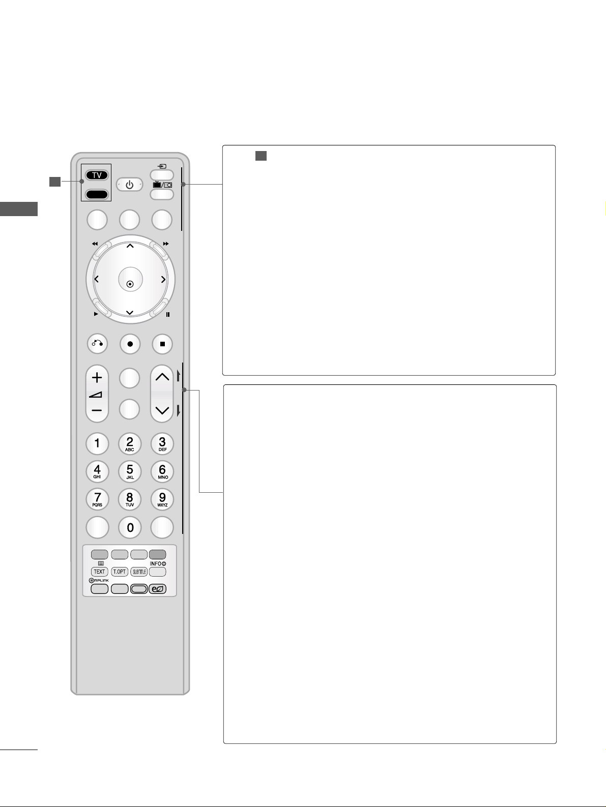
REMOTE CONTROL KEY FUNCTIONS
When using the remote control, aim it at the remote control sensor on the TV.
MODE
POWER
INPUT
TV/RAD
Q. MENU
MENU
GUIDE
Selects the remote operating modes.
Switches the TV on from standby or off to standby.
External input mode rotate in regular sequence.
Switches the TV on from standby.(
GG
pp..4466
)
Selects DTV, Radio and TV programme.
Displays the quick menu. (
GG
pp..2299
)
Displays main menu.
Clears all on-screen displays and returns to TV viewing
from any menu.(
GG
pp..3300~33 11
)
Shows programme schedule. (
GG
pp..5533
)
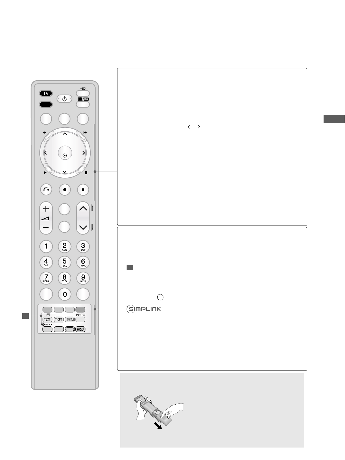
VOLUME UP
/DOWN
MARK
FAV
CHAR/NUM
DELETE
MUTE
Programme
UP/DOWN
PAGE
UP/DOWN
0~9 number
button
LIST
Q.VIEW
Adjusts the volume.
Check and un-check programmes in the USB menu or
Recorded TV menu.
Displays the selected favourite programme.(
GG
pp..4444
)
Used to edit programme title in REC.LIST and schedule list.
Switches the sound on or off.
Selects a programme.
Move from one full set of screen information to the next
one.
Selects a programme.
Selects numbered items in a menu.
Use for character/number input.
Displays the programme table.(
GG
pp..4433
)
Returns to the previously viewed programme.
1
1
Q. MENU
POWER
❁❂✰
MENU
INPUT
TV/RAD
GUIDE
Time Machine
SHIFT
TIME
RETURN
EXIT
LIST
OK
RECORD
MARK
FAV
CHAR/NUM
MUTE
DELETE
STOP
LIVE
P
Q.VIEW
REPEAT
TIME
SHIFT
P
A
G
E
RATIO
AV MODE
ENERGY SAVING
27
WATCHING TV / PROGRAMME CONTROL
Installing Batteries
■
Open the battery compartment
cover on the back side and install
the batteries matching correct
polarity (+ with +, - with -).
■
Install two 1.5V AAA batteries.
Don’t mix old or used batteries with
new ones.
■
Close cover.
INPUT
TV/RAD
POWER
Q. MENU
MENU
Time Machine
RETURN
EXIT
OK
P
Q.VIEW
RATIO
REPEAT
AV MODE
P
A
G
E
LIST
❁❂✰
GUIDE
TIME
SHIFT
TIME
SHIFT
RECORD
STOP
LIVE
MARK
FAV
CHAR/NUM
DELETE
MUTE
ENERGY SAVING
THUMBSTICK
(Up/Down/Left
Right)
OK
Time Machine
control buttons
RETURN(EXIT)
RECORD
STOP
LIVE
Coloured
buttons
REPEAT
TELETEXT
BUTTONS
SUBTITLE
INFO i
RATIO
AV MODE
ENERGY SAVING
Allows you to navigate the on-screen menus and adjust
the system settings to your preference.
Arrow buttons.
Accepts your selection or displays the current mode.
FF
(Rewind),
GG
(Fast Forward), G (Playback)
,
ll ll
(Pause), , (Jump thumbnail)
(Freezes the current frame by pressing the
ll ll
(Pause) button.)
Allows the user to move return one step in an interactive
application or other user interaction function.
Selects button to record the watching programme or make
recording schedules.
Stops processing of time machine function. (Playback,
Record, etc)
Return to the live.
These buttons are used for teletext (on
TTEELLEETT EEXXTT
models only) ,
PPrrooggrraammmmee eedd ii tt,RReeccoorr dd ll ii sstt
,
MMuullttiimm eedd ii aa,GGuuii ddee,SScchh eedd uull ee ll ii sstt
.
Used for playing the Recorded TV function.
These buttons are used for teletext.
For further details, see the ‘Teletext’ section.(
GG
pp..112222
)
Recalls your preferred subtitle in digital mode.
Shows the present screen information.
See a list of AV devices connected to TV.
When you toggle this button, the Simplink menu appears
at the screen.(
GG
pp..4477
)
Selects your desired picture format.
It helps you select and set images and sounds when connecting AV devices.(
GG
pp..5511
)
Adjust the Energy Saving mode of the TV.(
GG
pp..9911
)
2
2
28
WATCHING TV / PROGRAMME CONTROL
WATCHING TV / PROGRAMME CONTROL
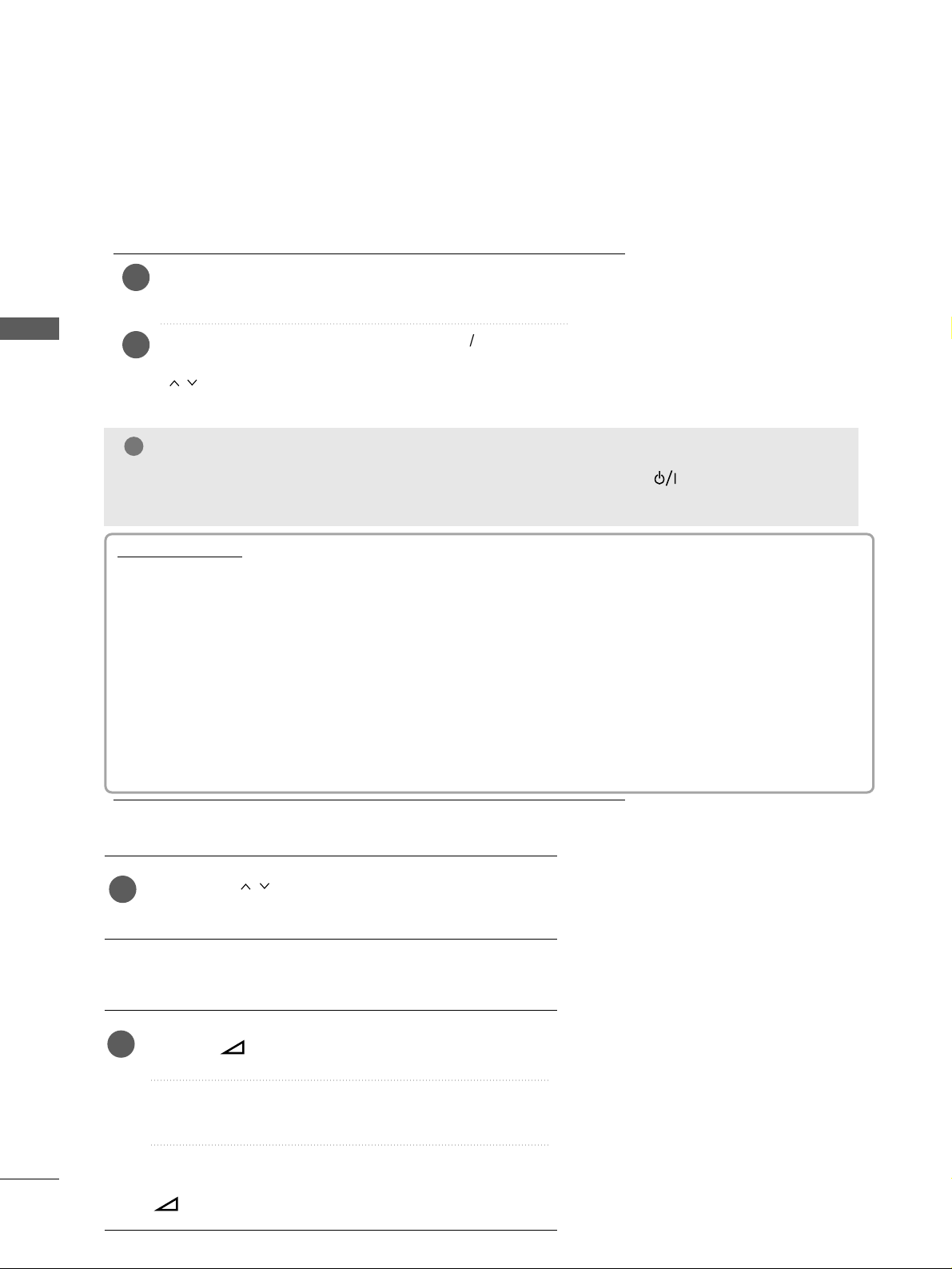
TURNING ON THE TV
Firstly, connect the power cord correctly.
At this stage, the TV switches to standby mode.
In standby mode to turn TV on, press the
rr
/ I, INPUT or
P
D E
button on the TV or press the POWER, INPUT, P
or NUMBER button on the remote control and the
TV will switch on.
2
1
- When your TV is turned on, you will be able to use its features.
PROGRAMME SELECTION
Press the
PP
or NUMBER buttons to select a programme
number.
1
VOLUME ADJUSTMENT
Press the
++ or--
button to adjust the volume.
If you wish to switch the sound off, press the MUTE button.
You can cancel this function by pressing the MUTE,
++ or--
button.
1
Initialising setup
Note:
a. If you close without completing the initial setting, the Initial Setting menu can be displayed again.
b. Press the RETURN button to change the current OSD to the previous OSD.
c. For those countries without confirmed DTV broadcasting standards, some DTV features might not
work, depending on the DTV broadcasting environment.
d. "Home Use” mode is the optimal setting for home environments, and is the TV's default mode.
e. "Store Demo" mode is the optimal setting for store environments. If a user modifies image quality
data, “Store Demo” mode initializes the product to the image quality set by us after a certain period of time.
f. The mode (Home Use, Store Demo) can be changed by executing Mode Setting in the OPTION
menu.
If the OSD (On Screen Display) is displayed on the screen after turning on the TV, you can adjust the
MMooddee SSee ttttii nngg,, TTiimm ee ZZoo nnee, TTiimmee MMaacchh ii nnee SSeettttiinn gg, AAuuttoo ttuu nnii nngg
.
NOTE
!
GG
If the TV is unplugged once or turn off with the AC power control switch (or (power) button) on the
TV, the time setting is set to
AAuu ttoo
to set time automatically.
 Loading...