

LG 50PQ10R Owner's Manual [es]
Please read this manual carefully before operating
your set and retain it for future reference.
The model and serial number of the TV is located
on the back and one side of the TV.
Record it below should you ever need service.
Model:
Serial:
PLASMA TV
OWNER’S MANUAL
P/NO : MFL58486313 (0906-REV00)
Printed in Korea
www.lge.com
42PQ10R
50PQ10R
To view the extended version of owner’s
manual that contains the advanced features of these TV sets, visit our website at
hhttttpp::////wwwwww..llggee..ccoomm
MFL58486313en 6/18/09 1:51 PM Page 1
2
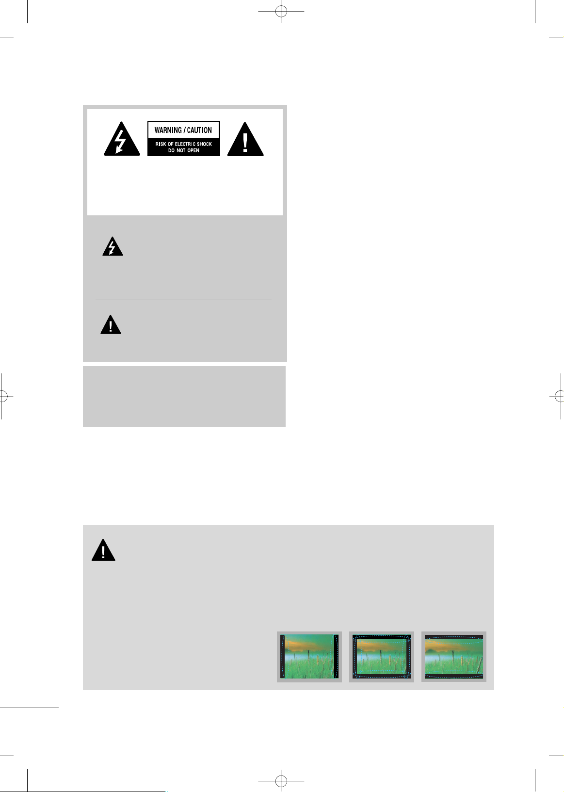
WARNING / CAUTION
The lightning flash with arrowhead symbol,
within an equilateral triangle, is intended
to alert the user to the presence of unin-
sulated “dangerous voltage” within the
product’s enclosure that may be of sufficient magnitude to constitute a risk of electric shock to persons.
The exclamation point within an equilat-
eral triangle is intended to alert the user
to the presence of important operating
and maintenance (servicing) instructions in the literature accompanying the appliance.
TO REDUCE THE RISK OF ELECTRIC SHOCK
DO NOT REMOVE COVER (OR BACK). NO
USER SERVICEABLE PARTS INSIDE. REFER TO
QUALIFIED SERVICE PERSONNEL.
WARNING/CAUTION
TO REDUCE THE RISK OF FIRE AND ELECTRIC
SHOCK, DO NOT EXPOSE THIS PRODUCT TO
RAIN OR MOISTURE.
■
When a fixed image (e.g. logos, screen menus, video game, and computer display) is displayed on the TV
for an extended period, it can become permanently imprinted on the screen. This phenomenon is known
as “image burn” or “burn-in.” Image burn is not covered under the manufacturer’s warranty.
■
In order to prevent image burn, avoid displaying a fixed image on your TV screen for a prolonged period
(2 or more hours for LCD, 1 or more hours for Plasma).
■
Image burn can also occur on the letterboxed
areas of your TV if you use the 4:3 aspect
ratio setting for an extended period.
IMPORTANT INFORMATION TO PREVENT “IMAGE BURN
/ BURN-IN” ON YOUR TV SCREEN
MFL58486313en 6/18/09 1:51 PM Page 2
3
IMPORTANT SAFETY INSTRUCTIONS
SAFETY INSTRUCTIONS
Read these instructions.
Keep these instructions.
Heed all warnings.
Follow all instructions.
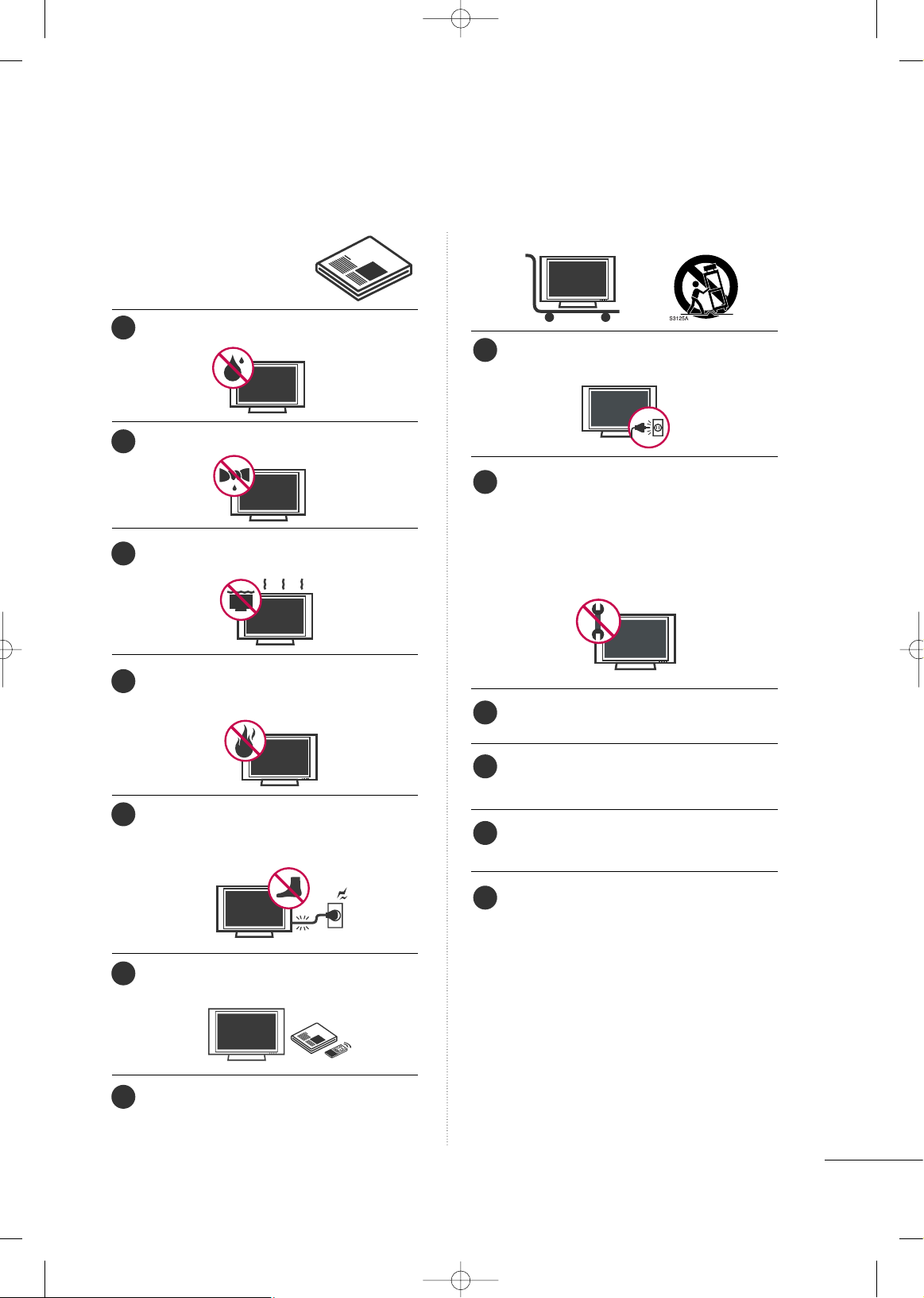
Do not use this apparatus near water.
Clean only with dry cloth.
Do not block any ventilation openings. Install in
accordance with the manufacturer’s instructions.
Do not install near any heat sources such as radiators, heat registers, stoves, or other apparatus
(including amplifiers)that produce heat.
Protect the power cord from being walked on or
pinched particularly at plugs, convenience
receptacles, and the point where they exit from
the apparatus.
Only use attachments/accessories specified by
the manufacturer.
Use only with the cart, stand, tripod, bracket, or
table specified by the manufacturer, or sold with
the apparatus. When a cart is used, use caution
when moving the cart/apparatus combination
to avoid injury from tip-over.
Unplug this apparatus during lighting storms or
when unused for long periods of time.
Refer all servicing to qualified service personnel. Servicing is required when the apparatus
has been damaged in any way, such as powersupply cord or plug is damaged, liquid has
been spilled or objects have fallen into the
apparatus, the apparatus has been exposed
to rain or moisture, does not operate normally, or has been dropped.
Never touch this apparatus or antenna during a thunder or lighting storm.
When mounting a TV on the wall, make sure
not to install the TV by the hanging power
and signal cables on the back of the TV.
Do not allow an impact shock or any objects
to fall into the product, and do not drop
onto the screen with something.
CAUTION concerning the Power Cord:
It is recommend that appliances be placed
upon a dedicated circuit; that is, a single outlet circuit which powers only that appliance and has no additional outlets or branch
cir
cuits. Check the specification page of this
owner's manual to be certain.
Do not connect too many appliances to the same
AC power outlet as this could result in fire or
electric shock.
Do not overload wall outlets. Overloaded wall
outlets, loose or damaged wall outlets, extension
cords, frayed power cords, or damaged or
cracked wire insulation are dangerous. Any of
these conditions could result in electric shock
or fire.
1
8
9
10
11
12
13
2
3
4
5
6
7
MFL58486313en 6/18/09 1:51 PM Page 3
4
SAFETY INSTRUCTIONS
Periodically examine the cord of your appliance,
and if its appearance indicates damage or deterioration, unplug it, discontinue use of the appliance, and have the cord replaced with an exact
replacement part by an authorized servicer.
Protect the power cord from physical or
mechanical abuse, such as being twisted,
kinked, pinched, closed in a door, or walked
upon. Pay particular attention to plugs, wall
outlets, and the point where the cord exits the
appliance.
Do not make the TV with the power cord
plugged in. Do not use a damaged or loose
power cord. Be sure do grasp the plug when
unplugging the power cord. Do not pull on the
power cord to unplug the TV.
WARNING - To reduce the risk of fire or electrical shock, do not expose this product to rain,
moisture or other liquids. Do not touch the TV
with wet hands. Do not install this product near
flammable objects such as gasoline or candles
or expose the TV to direct air conditioning.
Do not expose to dripping or splashing and do
not place objects filled with liquids, such as
vases, cups, etc. on or over the apparatus (e.g.
on shelves above the unit).
GGRR OOUU NNDDIINNGG
Ensure that you connect the earth ground wire
to prevent possible electric shock (i.e. a TV
with a three-prong grounded AC plug must be
connected to a three-prong grounded AC outlet). If grounding methods are not possible,
have a qualified electrician install a separate
circuit breaker.
Do not try to ground the unit by connecting it
to telephone wires, lightening rods, or gas pipes.
DDIISSCCOONNNNEECCTTIINNGG DDEEVVIICCEE FFRROOMM MMAAIINNSS
Mains plug is the disconnecting device. The
plug must remain readily operable.
As long as this unit is connected to the AC wall
outlet, it is not disconnected from the AC
power source even if you turn off this unit by
SWITCH (Some models).
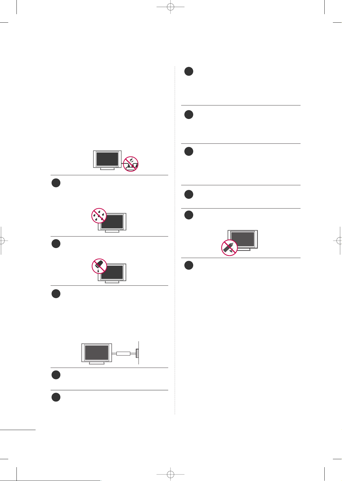
CClleeaanniinngg
When cleaning, unplug the power cord and
scrub gently with a soft cloth to prevent
scratching. Do not spray water or other liquids
directly on the TV as electric shock may occur.
Do not clean with chemicals such as alcohol,
thinners or benzene.
MMoovviinngg
Make sure the product is turned off,
unplugged and all cables have been removed. It
may take 2 or more people to carry larger TVs.
Do not press against or put stress on the front
panel of the TV.
VVee nn ttiillaattiioonn
Install your TV where there is proper ventila-
tion. Do not install in a confined space such as
a bookcase. Do not cover the product with
cloth or other materials (e.g.) plastic while
plugged in. Do not install in excessively dusty
places.
If you smell smoke or other odors coming from
the TV or hear strange sounds, unplug the
power cord contact an authorized service center.
Do not press strongly upon the panel with
hand or sharp object such as nail, pencil or
pen, or make a scratch on it.
Keep the product away from direct sunlight.
Power
Supply
Short-circuit
Breaker
14
20
19
21
22
23
24
15
16
17
18
MFL58486313en 6/18/09 1:51 PM Page 4
5
CONTENTS
is a trademark of SRS Labs, Inc.
TruSurround XT technology is incorporated under
license from SRS Labs, Inc.
Manufactured under license from Dolby Laboratories.
“
Dolby
“and the double-D symbol are trademarks of
Dolby Laboratories.
HDMI, the HDMI logo and High-Definition Multimedia
Interface are trademarks or registered trademarks of
HDMI Licensing LLC."
■
This feature is not available for all models.
FEATURES OF THIS TV
TO VIEW THE EXTENDED VERSION OF OWNER’S MANUAL
To view the extended version of owner’s manual that contains the advanced features of these TV sets, visit
our website at http://www.lge.com
Connect at www.lge.com Select your Region Select SUPPORT Find Product Support and
select Owner’s Manuals Enter your Model No. and then press Search
WARNING / CAUTION
. . . . . . . . . . . . . . . . . . . . . . . . . . . . 2
SAFETY INSTRUCTIONS
. . . . . . . . . . . . . . . . . . . . . . . . . . 3
PREPARATION
To view the extended version of owner’s manual . . 5
Features of this TV
. . . . . . . . . . . . . . . . . . . . . . . . . . . . . . . . . . . . . . . . . . . . 5
Accessories
. . . . . . . . . . . . . . . . . . . . . . . . . . . . . . . . . . . . . . . . . . . . . . . . . . . . . . .6
Front Panel Information
. . . . . . . . . . . . . . . . . . . . . . . . . . . . . . . . . . . . . .7
Back Panel Information
. . . . . . . . . . . . . . . . . . . . . . . . . . . . . . . . . . . . . . 8
Stand Instruction
. . . . . . . . . . . . . . . . . . . . . . . . . . . . . . . . . . . . . . . . . . . . . . 9
Desktop Pedestal Installation
. . . . . . . . . . . . . . . . . . . . . . . . . . .10
Swivel Stand
. . . . . . . . . . . . . . . . . . . . . . . . . . . . . . . . . . . . . . . . . . . . . . . . . . . . 10
Cable Arrangement
. . . . . . . . . . . . . . . . . . . . . . . . . . . . . . . . . . . . . . . . . .10
Remote Control Functions
. . . . . . . . . . . . . . . . . . . . . . . . . . . . . . . . 11
VESA Wall Mounting
. . . . . . . . . . . . . . . . . . . . . . . . . . . . . . . . . . . . . . . . 12
Securing the TV to the wall to prevent falling
When the TV is used on a stand
. . . . . . . . . . . . . . . . . . . . . . . . . . 13
Antenna or Cable Connection
. . . . . . . . . . . . . . . . . . . . . . . . . . 14
EXTERNAL EQUIPMENT SETUP
HD Receiver Setup
. . . . . . . . . . . . . . . . . . . . . . . . . . . . . . . . . . . . . . . . .15
DVD Setup
. . . . . . . . . . . . . . . . . . . . . . . . . . . . . . . . . . . . . . . . . . . . . . . . . . . . . . 16
VCR Setup
. . . . . . . . . . . . . . . . . . . . . . . . . . . . . . . . . . . . . . . . . . . . . . . . . . . . . 17
WATCHING TV
Turning On the TV . . . . . . . . . . . . . . . . . . . . . . . . . . . . . . . . . . . . . . . . . . . 18
Channel Selection
. . . . . . . . . . . . . . . . . . . . . . . . . . . . . . . . . . . . . . . . . . . . 18
Volume Adjustment
. . . . . . . . . . . . . . . . . . . . . . . . . . . . . . . . . . . . . . . . . .18
Channel Setup
. . . . . . . . . . . . . . . . . . . . . . . . . . . . . . . . . . . . . . . . . . . . . . . .19
Initializing setup (mode setting)
. . . . . . . . . . . . . . . . . . . . . . . 20
Quick Menu
. . . . . . . . . . . . . . . . . . . . . . . . . . . . . . . . . . . . . . . . . . . . . . . . . . . . 21
Favorite channel setup
. . . . . . . . . . . . . . . . . . . . . . . . . . . . . . . . . . . . . 22
Favorite channel list
. . . . . . . . . . . . . . . . . . . . . . . . . . . . . . . . . . . . . . . . .22
On-Screen Menus Selection
. . . . . . . . . . . . . . . . . . . . . . . . . . . . . 23
APPENDIX
Troubleshooting . . . . . . . . . . . . . . . . . . . . . . . . . . . . . . . . . . . . . . . . . . . . . . 25
Maintenance
. . . . . . . . . . . . . . . . . . . . . . . . . . . . . . . . . . . . . . . . . . . . . . . . . . . 27
Product Specifications
. . . . . . . . . . . . . . . . . . . . . . . . . . . . . . . . . . . . . 27
MFL58486313en 6/18/09 1:51 PM Page 5
PREPARATION
6
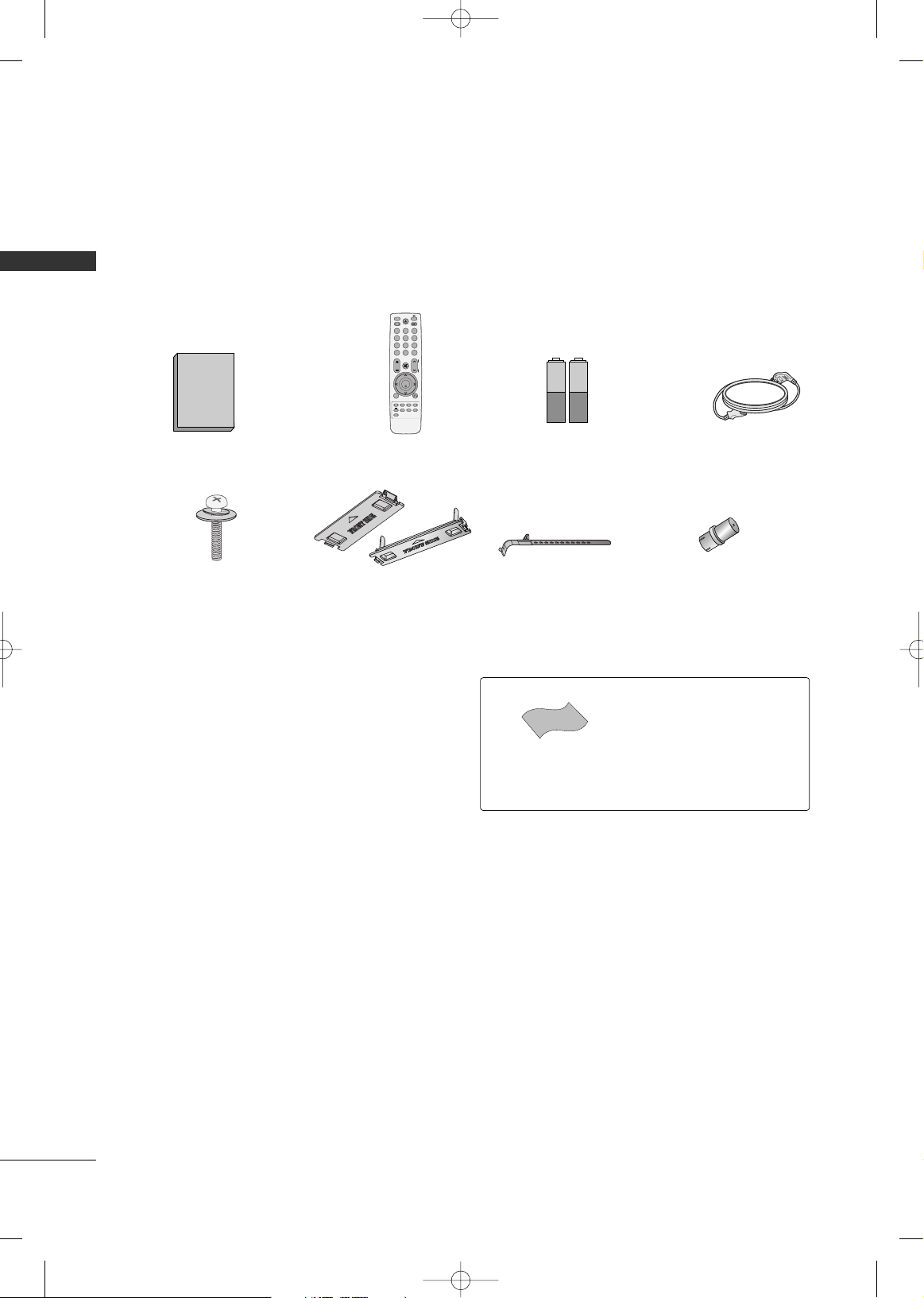
ACCESSORIES
PREPARATION
Ensure that the following accessories are included with your TV. If an accessory is missing, please contact the
dealer where you purchased the product.
The accessories included may differ from the images below.
1.5V 1.5V
Owner’s Manual Power Cord
Remote Control
FAV
FREEZE
Q.MENU
MENU
LIST
123
456
7809
Q.VIEW
MUTE
VOL
CH
P
A
G
E
RETURN
ENTER
INPUT
POWER
AV MODE
POWER SAVING
RATIO
T.OPT
TEXT
Bolts for stand assembly
(Refer to P.9)
x 4
Cable Holder
(Refer to P.10)
* Wipe spots on the exterior only with
the polishing cloth.
* Do not wipe roughly when removing
stain. Excessive pressure may cause
scratch or discoloration.
Polishing Cloth
(Not included with all models.)
Protection Cover
(Refer to P.9)
Batteries
(Some models)
RF Adapter
(Some models)
You must connect it to the antenna
wire after fixing in Antenna Input.
This adapter is only supplied in
AA rrggeenn ttiinnaa
.
x 2
or
MFL58486313en 6/18/09 1:51 PM Page 6
PREPARATION
7
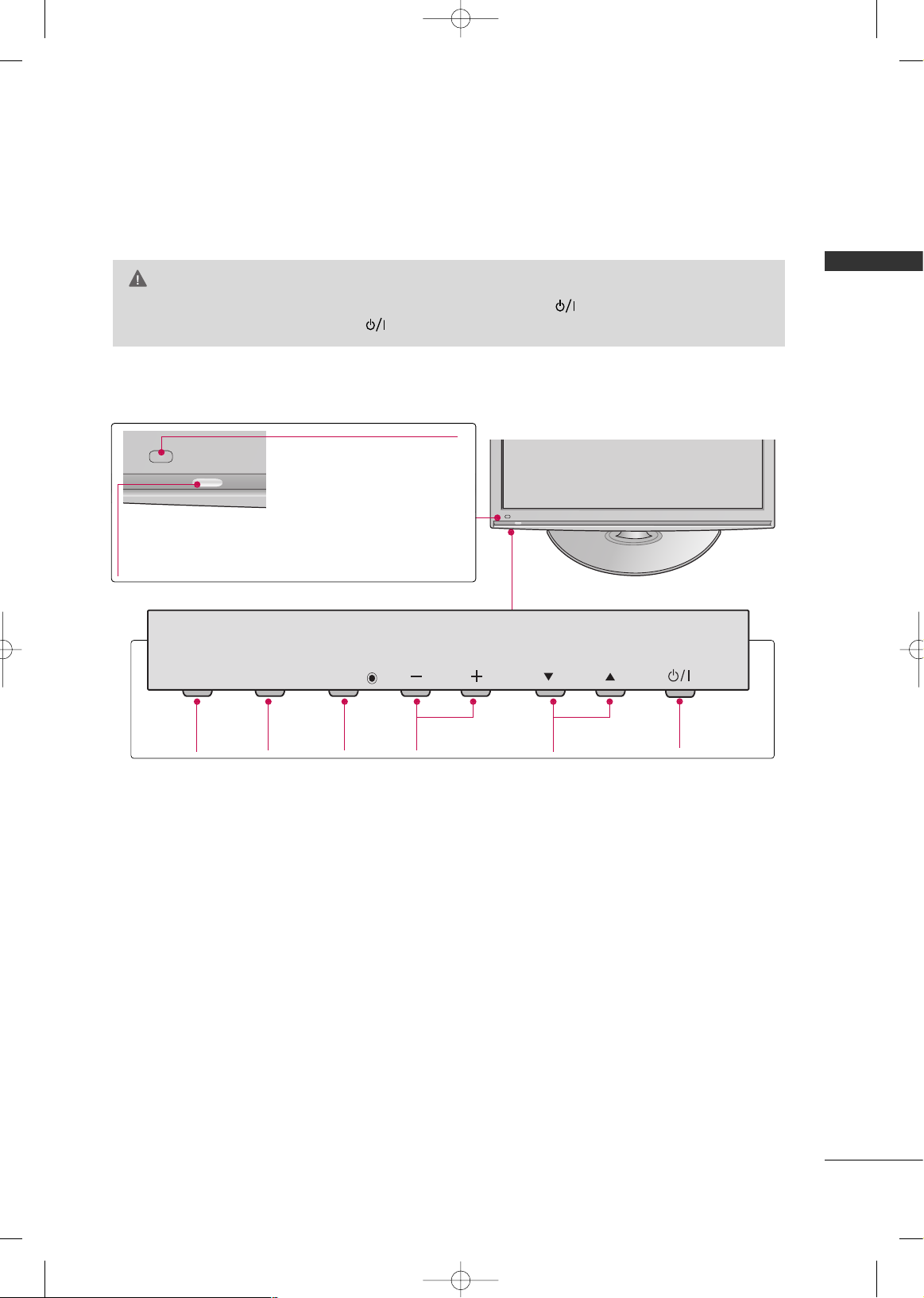
FRONT PANEL INFORMATION
■
Image shown may differ from your TV.
GG
When the TV cannot be turned on with the remote control, press the (power) button on the TV. (The
remote control will not work when the (power) button on the TV is switched off. )
CAUTION
CH
VOL
MENU
INPUT
ENTER
INPUT
Button
POWER
Button
MENU
Button
ENTER
Button
VOLUME
(-, +) Buttons
CHANNEL
(
EE,DD
)Buttons
Power/Standby Indicator
Illuminates red in standby mode.
Illuminates blue when the TV is switched on.
Remote Control Sensor
MFL58486313en 6/18/09 1:51 PM Page 7
INPUT
MENU
ENTER
VOL
CH
PREPARATION
8
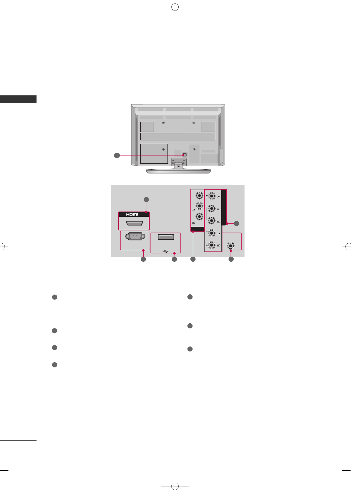
BACK PANEL INFORMATION
PREPARATION
RS-
232
C IN
(CONTROL & SERVICE)
ANTENNA
IN
COMPONENT IN
VIDEO
AUDIO
R
B
IN
USB IN
SERVICE ONLY
IN
VIDEO
MONO
( )
AUDIO
-
-
AV
1
2 4
5
63
7
HDMI
Digital Connection. Supports HD video and Digital
audio.
Accepts DVI video using an adapter or HDMI to
DVI cable (not included)
RS-232C IN (CONTROL & SERVICE) PORT
Used by third party devices.
USB IN SERVICE ONLY
Used for software updates.
AV (Audio/Video) IN
Analog composite connection. Supports standard
definition video only (480i).
COMPONENT IN
Analog Connection. Supports SD/HD.
Uses a red, green, and blue cable for video & red
and white for audio.
ANTENNA IN
Connect over-the air signals to this jack.
Connect cable signals to this jack.
Power Cord Socket
For operation with AC power.
Caution: Never attempt to operate the TV on DC
power.
1
2
3
4
7
5
6
■
Image shown may differ from your TV.
MFL58486313en 6/18/09 1:51 PM Page 8
PREPARATION
9
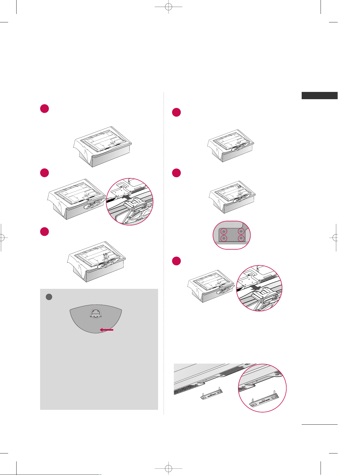
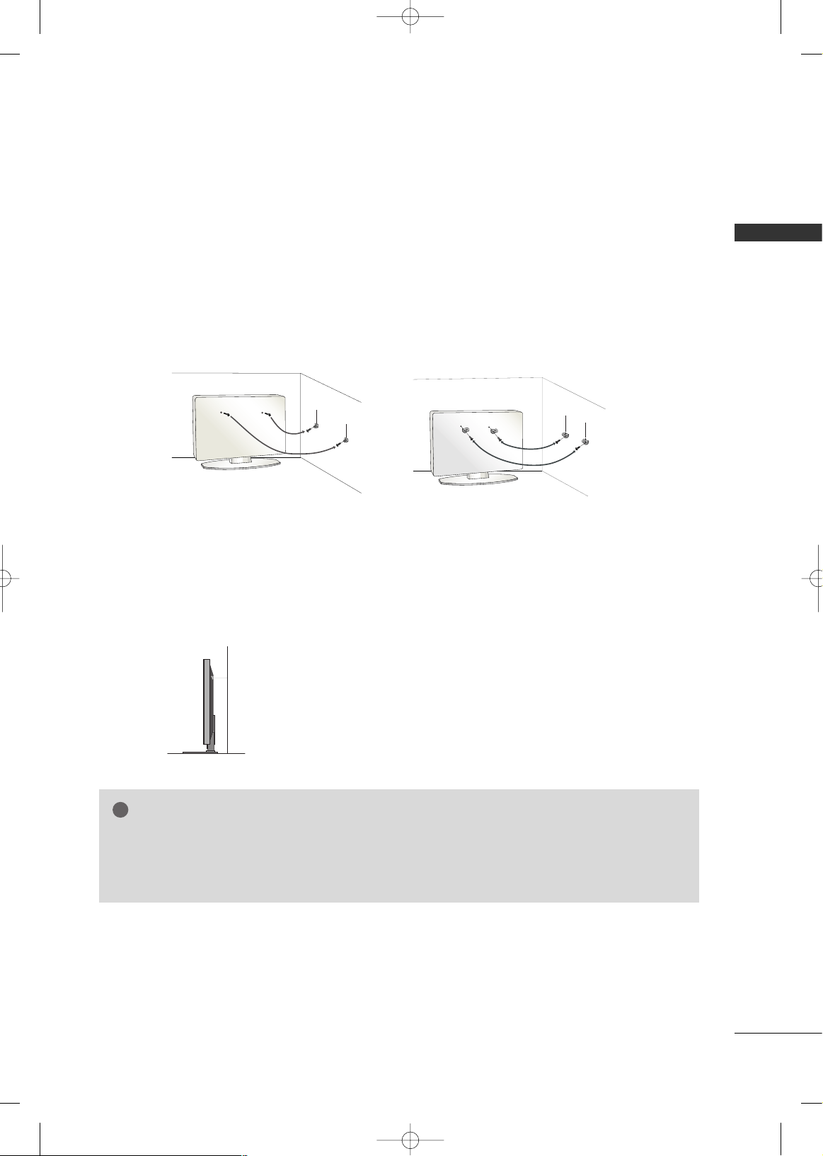
STAND INSTRUCTION
■
Image shown may differ from your TV.
Carefully place the TV screen side down on a
cushioned surface to protect the screen from
damage.
Assemble the TV as shown.
1
2
Fix the 4 bolts securely using the holes in the
back of the TV.
3
Carefully place the TV screen side down on a
cushioned surface to protect the screen from
damage.
1
Loose the bolts from TV.
2
Detach the stand from TV.
3
After removing the stand, install the included
pp rrootteeccttii oonn ccoo vveerr
over the hole for the stand.
Press the
PPRROOTTEECCTTIIOONN CCOOVVEERR
into the TV
until you hear it click.
PROTECTION COVER
Installation Detachment
GG
When assembling the stand, make sure to distinguish
and assemble the front and rear side of the stand
correctly.
GG
When assembling the desk type stand, check
whether the bolt is fully tightened. (If not tightened fully, the product can tilt forward after the
product installation). If you tighten the bolt
with excessive force, the bolt can deviate from
abrasion of the tightening part of the bolt.
NOTE
!
FRONT
MFL58486313en 6/18/09 1:51 PM Page 9
PREPARATION
10
PREPARATION
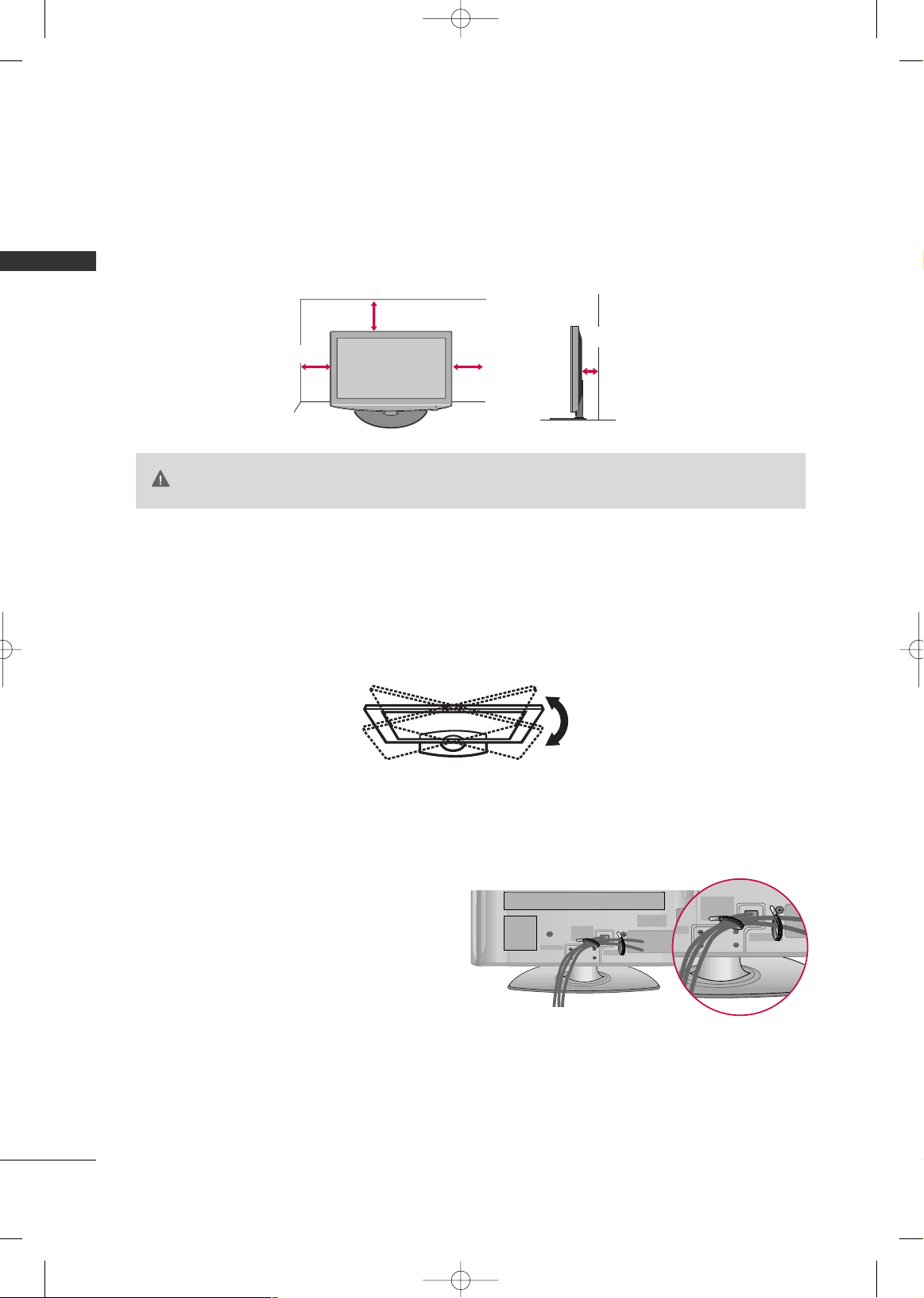
DESKTOP PEDESTAL INSTALLATION
For proper ventilation, allow a clearance of 4 inches on all four sides from the wall.
■
Image shown may differ from your TV.
SWIVEL STAND
(This feature is not available for all models.)
After installing the TV, you can adjust the TV set manually to the left or right direction by 20 degrees to suit
your viewing position.
GG
Ensure adequate ventilation by following the clearance recommendations.
GG
Do not mount near or above any type of heat source.
CAUTION
4 inches
4 inches
4 inches
4 inches
CABLE ARRANGEMENT
■
Image shown may differ from your TV.
After connecting the cables as necessary, install
CABLE HOLDER as shown and bundle the cables.
MFL58486313en 6/18/09 1:51 PM Page 10
PREPARATION
11
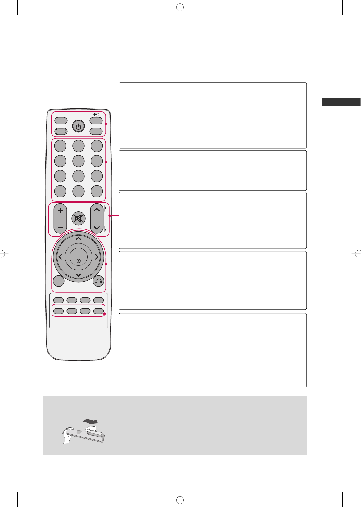
REMOTE CONTROL FUNCTIONS
Installing Batteries
■
Open the battery compartment cover on the back side and install the batteries matching correct polarity.
■
Install two 1.5V AAA batteries. Don’t mix old or used batteries with new
ones.
■
Close cover.
FAV
FREEZE
Q.MENU
MENU
LIST
123
456
7809
Q.VIEW
MUTE
VOL
CH
P
A
G
E
RETURN
ENTER
INPUT
POWER
AV MODE
POWER SAVING
RATIO
SLEEP
RATIO
INPUT
AV MODE
POWER SAVING
POWER
Changes the aspect ratio of the video.
Rotates through inputs.
Also switches the TV on from standby.
Toggles through preset Video and Audio modes.
Adjusts the Power Saving.
Turns the TV on from standby or off to standby.
NUMBER button
LIST
Q.VIEW
Used to enter a program number for multiple
program channels.
Displays the channel list.
Tune to the last channel viewed.
Adjusts the volume.
Switches the sound on or off.
Changes the channel.
Moves from one full set of screen information to the next one.
VOLUME UP
/DOWN
MUTE
CHANNEL
UP/DOWN
PAG E
UP/DOWN
THUMBSTICK
(Up/Down/Left
Right/ENTER)
MENU
RETURN
Navigates the on-screen menus and adjusts the system settings to your preference.
Displays the main menu or clears all on-screen displays and
returns to TV viewing.
Allows the user to move return one step in an interactive
application or other user interaction function.
Q.MENU
FREEZE
SLEEP
FAV
Opens the list of Quick Menu options.
Freezes the current frame.
The TV returns to normal viewing automatically if no signal
is received or no operation is performed for 5 minutes.
It doesn’t work at USB mode.
Select the amount of time before your TV turns off automatically.
Scroll through the programmed Favorite channels.
MFL58486313en 6/18/09 1:51 PM Page 11
PREPARATION
12
PREPARATION
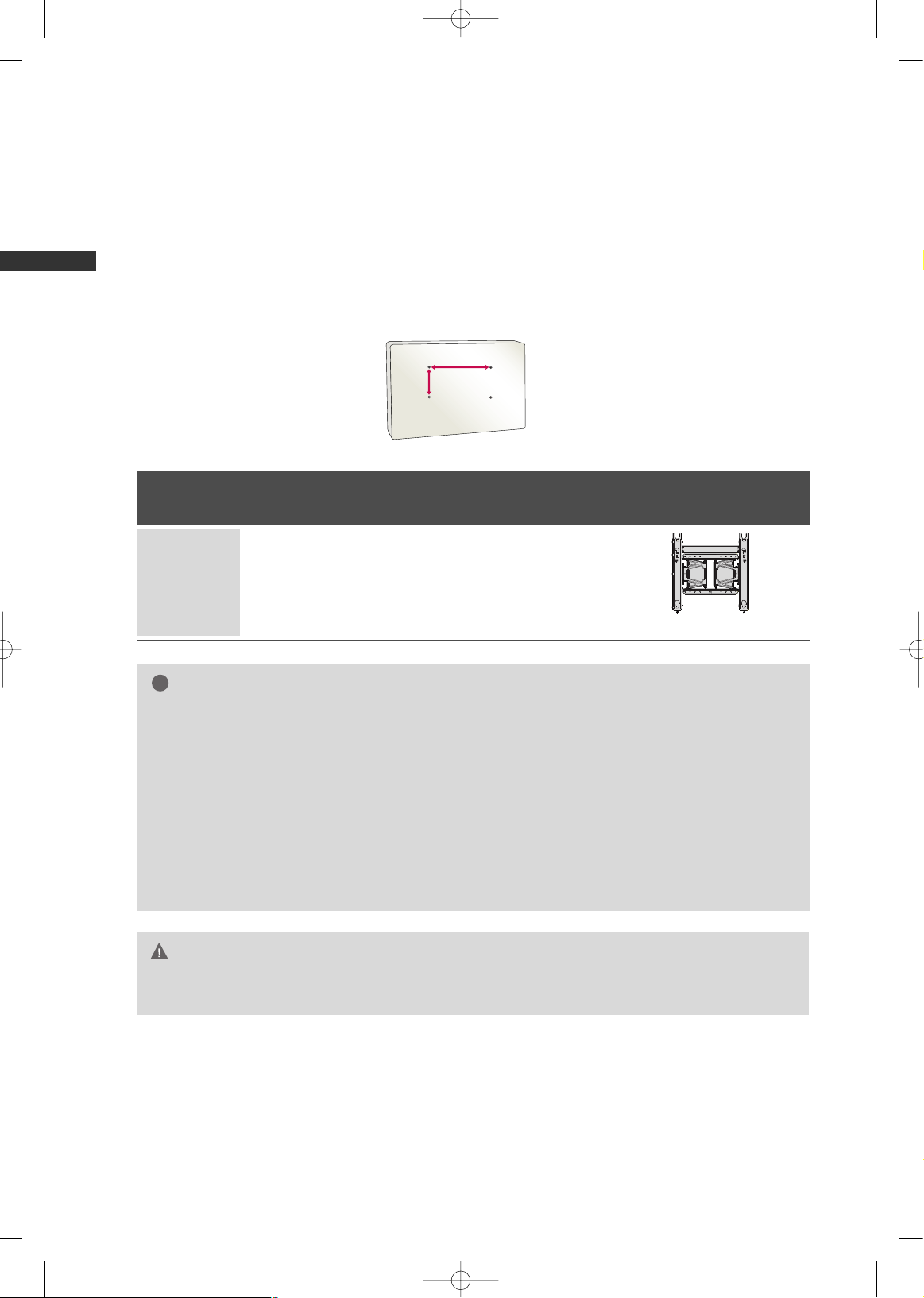
VESA WALL MOUNTING
Install your wall mount on a solid wall perpendicular to the floor. When attaching to other building materials, please
contact your nearest installer.
If installed on a ceiling or slanted wall, it may fall and result in severe personal injury.
We recommend that you use an LG brand wall mount when mounting the TV to a wall.
LG recommends that wall mounting be performed by a qualified professional installer.
GG
Do not install your Wall Mount Bracket while your TV is turned on. It may result in personal injury due to
electric shock.
CAUTION
GG
Screw length needed depends on the wall mount
used. For further information, refer to the instructions included with the mount.
GG
Standard dimensions for wall mount kits are shown
in the table.
GG
When purchasing our wall mount kit, a detailed
installation manual and all parts necessary for
assembly are provided.
GG
Do not use screws longer then the standard dimension, as they may cause damage to the inside to
the TV.
GG
For wall mounts that do not comply with the VESA
standard screw specifications, the length of the
screws may differ depending on their specifications.
GG
Do not use screws that do not comply with the
VESA standard screw specifications.
Do not fasten the screws too strongly. This may
damage the TV or cause the TV to a fall, leading to
personal injury. LG is not liable for these kinds of
accidents.
GG
LG is not liable for TV damage or personal injury
when a non-VESA or non specified wall mount is
used or the consumer fails to follow the TV installation instructions.
NOTE
!
AA
BB
Models
VESA
(A *B)
Standard Screw Quantity
400* 400 M6 4
42PQ10R,
50PQ10R
Wall Mounting Bracket
(sold separately)
(AW-50PG60MS)
MFL58486313en 6/18/09 1:51 PM Page 12
PREPARATION
13
SECURING THE TV TO THE WALL TO PREVENT FALLING
WHEN THE TV IS USED ON A STAND
We recommend that you set up the TV close to a wall so it cannot fall over if pushed backwards.
Additionally, we recommend that the TV be attached to a wall so it cannot be pulled in a forward direction,
potentially causing injury or damaging the product.
Caution: Please make sure that children don’t climb on or hang from the TV.
■
Insert the eye-bolts (or TV brackets and bolts) to tighten the product to the wall as shown in the picture.
*If your product has the bolts in the eye-bolts position before inserting the eye-bolts, loosen the bolts.
* Insert the eye-bolts or TV brackets/bolts and tighten them securely in the upper holes.
Secure the wall brackets with the bolts (sold separately) to the wall. Match the height of the bracket that is
mounted on the wall to the holes in the product.
Ensure the eye-bolts or brackets are tightened securely.
■
Use a sturdy rope (sold separately) to tie the product. It is safer to tie
the rope so it becomes horizontal between the wall and the product.
■
You should purchase necessary components to prevent the TV from tipping over (when not using a wall mount).
■
Image shown may differ from your TV.
GG
Use a platform or cabinet strong enough and large enough to support the size and weight of the TV.
GG
To use the TV safely, make sure that the height of the bracket on the wall and the one on the TV are
the same.
NOTE
!
MFL58486313en 6/18/09 1:51 PM Page 13
PREPARATION
14
PREPARATION
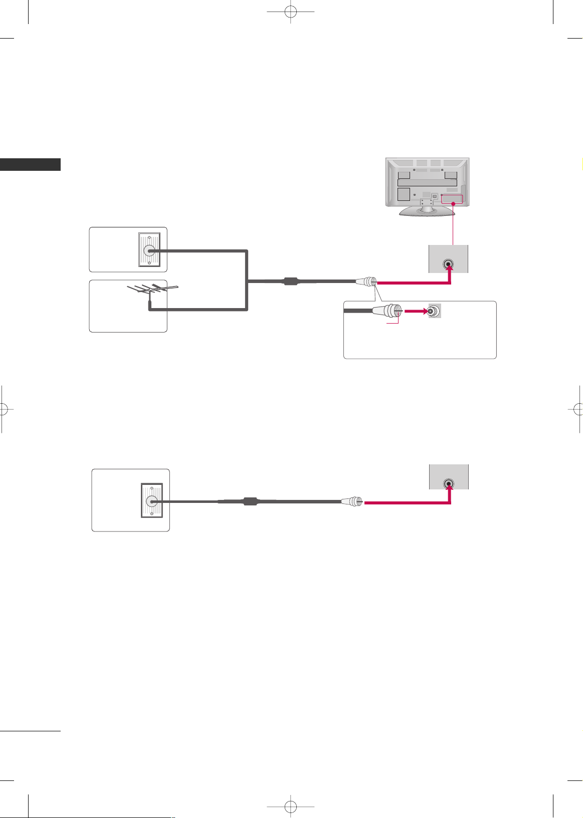
ANTENNA OR CABLE CONNECTION
■
To prevent damage do not connect to the power outlet until all connections are made between the devices.
■
Image shown may differ from your TV.
1. Antenna (Analog)
Wall Antenna Socket or Outdoor Antenna without a Cable Box
Connection.
For optimum picture quality, adjust antenna direction if needed.
2. Cable
Wall
Antenna
Socket
Outdoor
Antenna
(VHF, UHF)
Cable TV
Wall Jack
Multi-family Dwellings/Apartments
(Connect to wall antenna socket)
RF Coaxial Wire (75 ohm)
RF Coaxial Wire (75 ohm)
Single-family Dwellings /Houses
(Connect to wall jack for outdoor antenna)
Be careful not to bend the copper wire
when connecting the antenna.
Copper Wire
( )
(
)
ANTENNA
IN
( )
(
)
■
To improve the picture quality in a poor signal area, please purchase a signal amplifier and install properly.
■
If the antenna needs to be split for two TV’s, install a 2-Way Signal Splitter.
■
If the antenna is not installed properly, contact your dealer for assistance.
MFL58486313en 6/18/09 1:51 PM Page 14
ANTENNA
IN
EXTERNAL EQUIPMENT SETUP
15
EXTERNAL EQUIPMENT SETUP
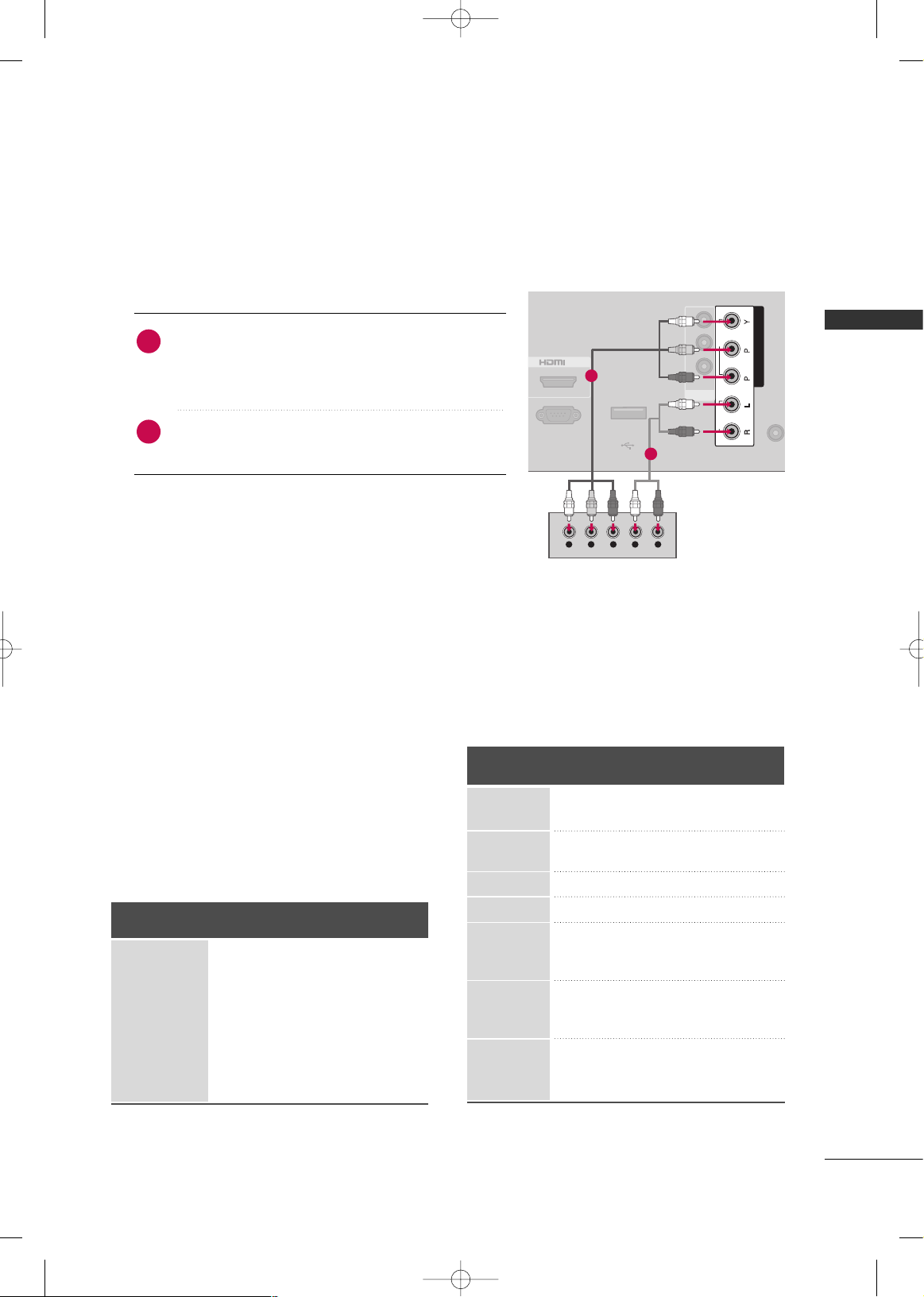
HD RECEIVER SETUP
■
To prevent the equipment damage, never plug in any power cords until you have finished connecting all equipment.
■
Image shown may differ from your TV.
Component Connection
1. How to connect
Connect the video outputs (Y, P
B, PR
)
of the digital set-
top box to the
CCOOMMPPOONNEENNTT IINN VVIIDDEEOO
jacks on the
TV. Match the jack colors (Y = green, P
B = blue, and PR
= red).
Connect the audio output of the digital set-top box to
the
CCOOMMPPOONNEENNTT IINN AAUUDDIIOO
jacks on the TV.
2
1
2. How to use
■
Turn on the digital set-top box.
(
Refer to the owner’s manual for the digital set-top box.
operation
)
■
Select the
CCoommppoo nn eenntt
input source on the TV
using the
IINNPPUUTT
button on the remote control.
ANTENN
IN
COMPONENT IN
IN
USB IN
SERVICE ONLY
IN
VIDEO
MONO
( )
AUDIO
-
-
AV
RS-232C IN
(CONTROL & SERVICE)
VIDEO
AUDIO
R
B
Y L RPBP
R
( )
1
2
Y, C
B/PB, CR/PR
Supported Resolutions
Horizontal Vertical
Frequency(KHz)Frequency(Hz
)
15.73 59.94
15.75 60.00
31.47 59.94
31.50 60.00
15.62 50.00
31.25 50.00
44.96 59.94
45.00 60.00
37.50 50.00
33.72 59.94
33.75 60.00
28.12 50.00
56.25 50.00
67.43 59.94
67.50 60.00
Resolution
720x480 i
720x480 p
128 0 x 720 p
1920 x108 0 i
1920x1080p
Signal
480i
480p
576i
576p
720 p
10 8 0 i
10 8 0 p
Component
Yes
Yes
Yes
Yes
Yes
Yes
Yes
HDMI
No
Yes
No
Yes
Yes
Yes
Yes
720x576i
720x576p
MFL58486313en 6/18/09 1:51 PM Page 15
EXTERNAL EQUIPMENT SETUP
16
EXTERNAL EQUIPMENT SETUP
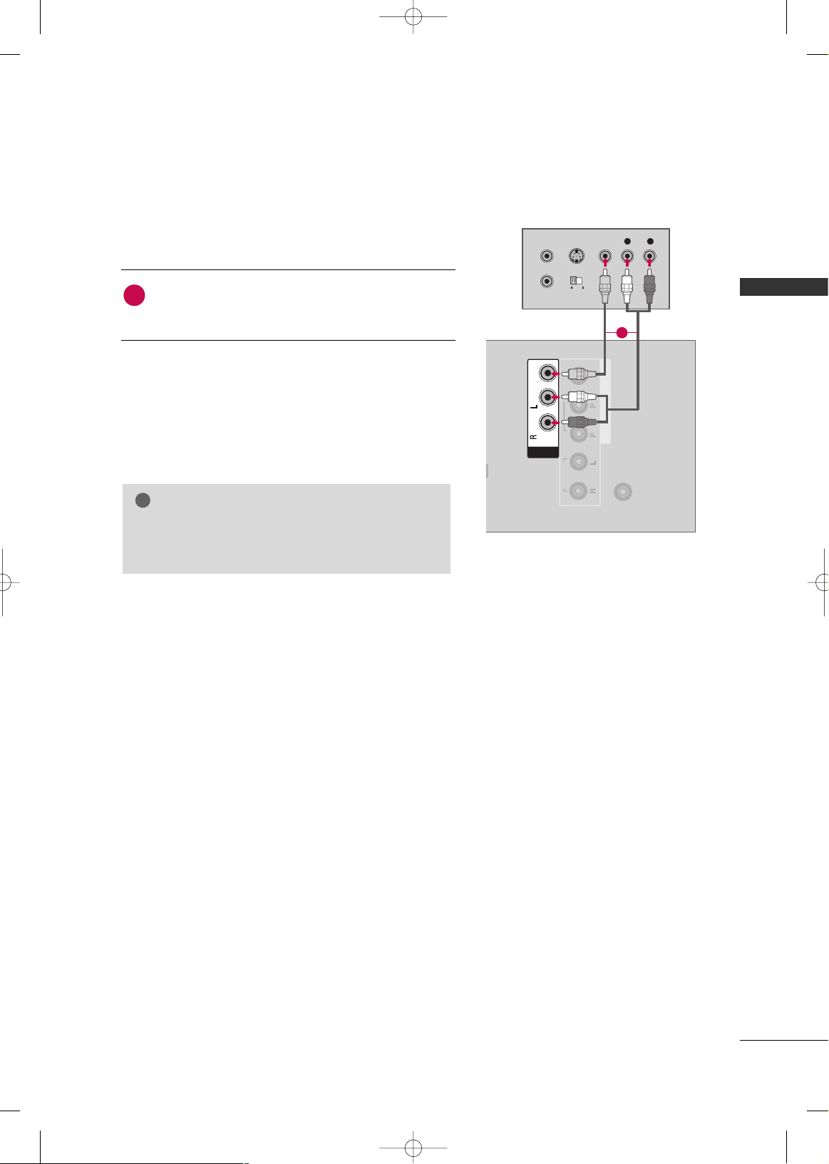
DVD SETUP
Component Connection
Connect the video outputs (Y, P B, P
R
)
of the DVD to the
CCOOMMPPOONNEENNTT IINN VVIIDDEEOO
jacks on the TV.
Match the jack colors (Y = green, P
B = blue, and PR = red
)
.
Connect the audio outputs of the DVD to the
CCOOMMPPOONNEENNTT IINN AAUUDDIIOO
jacks on the TV.
1. How to connect
2. How to use
■
Turn on the DVD player, insert a DVD.
■
Select the
CCoommppoo nn eenntt
input source on the TV using the
IINNPP UUTT
button on the remote control.
■
Refer to the DVD player's manual for operating instructions.
2
1
ANTEN
IN
COMPONENT IN
IN
USB IN
SERVICE ONLY
IN
VIDEO
MONO
( )
AUDIO
-
-
AV
RS-232C IN
(CONTROL & SERVICE)
VIDEO
AUDIO
R
B
Y L RPBP
R
( )
1
2
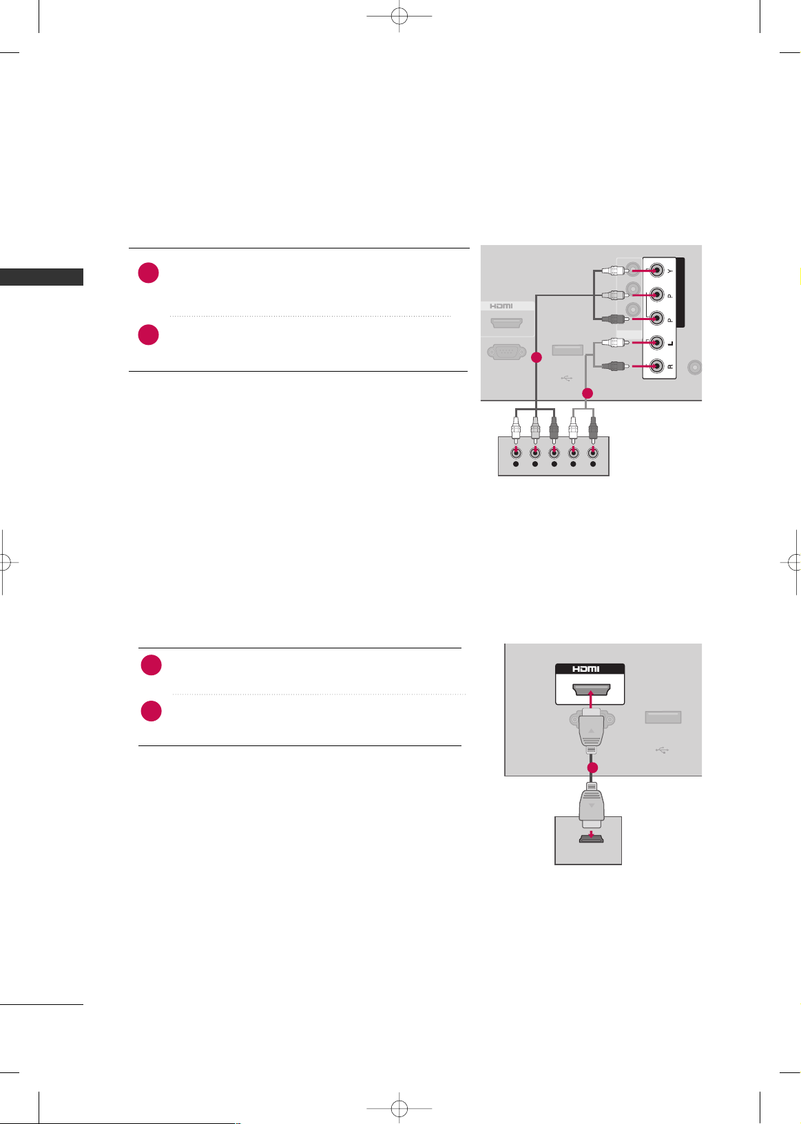
HDMI Connection
Connect the HDMI output of the DVD to the
HHDDMMII IINN
jack on the TV.
No separate audio connection is necessary.
HDMI supports both audio and video.
1. How to connect
2. How to use
■
Select the
HHDDMMII
input source on the TV using the
IINNPPUUTT
button on the remote control.
■
Refer to the DVD player's manual for operating instructions.
2
1
USB IN
SERVICE ONLY
( )
RS-232C IN
(CONTROL & SERVICE)
IN
HDMI-DTV OUTPUT
1
MFL58486313en 6/18/09 1:51 PM Page 16
EXTERNAL EQUIPMENT SETUP
17
VCR SETUP
Composite (RCA) Connection
Connect the
AAUU DDIIOO/VVIIDD EEOO
jacks between TV and
VCR. Match the jack colors (Video = yellow, Audio Left
= white, and Audio Right = red).
1. How to connect
2. How to use
■
Insert a video tape into the VCR and press PLAY on the
VCR. (Refer to the VCR owner’s manual
)
■
Select the
AAVV
input source on the TV using the
IINNPP UUTT
button on the remote control.
1
GG
If you have a mono VCR, connect the audio cable
from the VCR to the
AAUU DDIIOO LL((MMOONNOO ))
jack of
the TV.
NOTE
!
( )
(
)
(
)
ANTENNA
IN
COMPONENT IN
VIDEO
AUDIO
R
B
IN
VIDEO
MONO
( )
AUDIO
-
-
AV
L R
S-VIDEO VIDEO
OUTPUT
SWITCH
ANT IN
ANT OUT
1
MFL58486313en 6/18/09 1:51 PM Page 17
WATCHING TV
18
TURNING ON THE TV
NOTE
!
GG
If you intend to be away on vacation, disconnect the power plug from the wall power outlet.
GG
If you do not complete the Initial setting, it will appear whenever the TV is switched on until the Initial
setting procedure is completed.
GG
If the TV is unplugged once or turn off with the (power)button on the TV, reset the
CClloocckk
function.
(some models)
First, connect the power cord correctly.
At this moment, the TV is in standby mode.
■
In standby mode to turn TV on, press the
IINNPP UUTT,CCHH ((
EE
or
DD
))
button on the TV or press the
PPOOWWEERR
,
IINNPP UUTT, CCHH((
or )),
NNuummbbee rr (( 00~99))
button on the remote control.
Select the viewing source by using the
IINNPPUUTT
button on the remote control.
■
This TV is programmed to remember which power state it was last set to, even if the power cord is out.
1
2
Press the
CCHH ((
or ))or
NNUUMMBBEERR
buttons to select a channel number.
1
VOLUME ADJUSTMENT
CHANNEL SELECTION
Adjust the volume to suit your personal preference.
Press the
VVOOLL ((++
or
--))
button to adjust the volume.
If you want to switch the sound off, press the
MMUUTTEE
button.
You can cancel the Mute function by pressing the
MMUUTTEE, VVOOLL ((++
or
--)) orAAVV MMOODDEE
button.
1
2
3
WATCHING TV
MFL58486313en 6/18/09 1:51 PM Page 18
 Loading...