

LG 50PM4MWA Users manual
PLASMA
P/NO: MFL36274107 (0708-REV00)
Printed in Korea
MONITOR
MODELS:50PM4M
OWNER’S MANUAL
Please read this manual carefully before operating your set.
Retain it for future reference.
Record model number and serial number of the set.
See the label attached on the back cover and quote
this information to your dealer
when you require service.
1
WARNING / CAUTION
WARNING / CAUTION
To prevent fire or shock hazards, do not expose
this product to rain or moisture.
FCC NOTICE
Class B digital device
This equipment has been tested and found to comply
with the limits for a Class B digital device, pursuant to
Part 15 of the FCC Rules. These limits are designed
to provide reasonable protection against harmful
interference in a residential installation. This equipment
generates, uses and can radiate radio frequency energy
and, if not installed and used in accordance with the
instructions, may cause harmful interference to radio
communications. However, there is no guarantee that
interference will not occur in a particular installation.
If this equipment does cause harmful interference to
radio or television reception, which can be determined
by turning the equipment off and on, the user is
encouraged to try to correct the interference by one
or more of the following measures:
- Reorient or relocate the receiving antenna.
- Increase the separation between the equipment and
receiver.
- Connect the equipment to an outlet on a circuit
different from that to which the receiver is connected.
- Consult the dealer or an experienced radio/TV
technician for help.
Any changes or modifications not expressly approved
by the party responsible for compliance could void
the user’s authority to operate the equipment.
CAUTION
Do not attempt to modify this product in any way
without written authorization from LG Electronics.
Unauthorized modification could void the user’s
authority to operate this product
The lightning flash with arrowhead
symbol, within an equilateral triangle, is
intended to alert the user to the presence
of uninsulated “dangerous voltage” within the
product’s enclosure that may be of sufficient
magnitude to constitute a risk of electric shock to
persons.
The exclamation point within an equilateral
triangle is intended to alert the user to
the presence of important operating and
maintenance (servicing) instructions in the literature accompanying the appliance.
TO REDUCE THE RISK OF ELECTRIC SHOCK
DO NOT REMOVE COVER (OR BACK). NO
USER SERVICEABLE PARTS INSIDE. REFER TO
QUALIFIED SERVICE PERSONNEL.
WARNING/CAUTION
TO REDUCE THE RISK OF FIRE AND ELECTRIC
SHOCK, DO NOT EXPOSE THIS PRODUCT TO
RAIN OR MOISTURE.
NOTE TO CABLE/TV INSTALLER
This reminder is provided to call the CATV system
installer’s attention to Article 820-40 of the National
Electric Code (U.S.A.). The code provides guidelines for
proper grounding and, in particular, specifies that the
cable ground shall be connected to the grounding system
of the building, as close to the point of the cable entry
as practical.
2 Plasma Monitor
Safety Instructions
WARNING/CAUTION
TO REDUCE THE RISK OF FIRE AND ELECTRIC SHOCK, DO NOT EXPOSE THIS PRODUCT TO
RAIN OR MOISTURE.
Do not place the set in direct sunlight or near heat sources such as heat registers, stove and so on.
- This may cause a fire.
Do not use the set in damp place such as a bathroom or any place where it is likely to get wet.
- This may cause a fire or could give an electric shock.
Bend antenna cable between inside and outside building to prevent rain from flowing in.
- This may cause water damaged inside the set and could give an electric shock.
Earth wire should be connected.
- If the earth wire is not connected, there is possible a danger of electric shock caused by the current leakage.
- If grounding methods are not possible, a separate circuit breaker should be employed and installed by a qualified electrician.
- Do not connect ground to telephone wires, lightning rods or gas pipe.
Do not place anything containing liquid on top of the set.
- This may cause a fire or could give an electric shock.
Do not insert any object into the exhaust vent.
- This may cause a fire or could give an electric shock.
Do not place heavy objects on the set.
- This may cause serious injury to a child or adult.
Do not use water while cleaning the set.
- This may cause damaged the set or could give an electric shock.
In case of smoke or strange smell from the set, switch it off ,unplug it from the wall outlet and contact your dealer
or service center.
- This may cause a fire or could give an electric shock.
Do not attempt to service the set yourself. Contact your dealer or service center.
- This may cause damaged the set or could give an electric shock.
During a lightning thunder, unplug the set from the wall outlet and don’t touch an antenna cable.
- This may cause damaged the set or could give an electric shock.
WARNING
Safety Instructions
Safety Instructions
Owner’s Manual 3
ENGLISH
Safety Instructions
Never touch the power plug with a wet hand.
- This may cause an electric shock.
Disconnect from the mains and remove all connections before moving.
Do not place the set in a built-in installation such as a bookcase or rack.
- Ventilation required.
When installing the set on a table, be careful not to place the edge of its stand.
- This may cause the set to fall, causing serious injury to a child or adult, and serious damage to the set.
Do not place an outside antenna in the vicinity of overhead power lines or other electric light or power circuits.
- This may cause an electric shock.
There should be enough distance between an outside antenna and power lines to keep the former from touching the
latter even when the antenna falls.
- This may cause an electric shock.
Do not pull the cord but the plug when unplugging.
- This may cause a fire.
Ensure the power cord doesn’t trail across any hot objects like a heater.
- This may cause a fire or an electric shock.
Do not plug when the power cord or the plug is damaged or the connecting part of the power outlet is loose.
- This may cause a fire or an electric shock.
Dispose of used batteries carefully to protect a child from eating them.
- In case that it eats them, take it to see a doctor immediately.
When moving the set assembled with speakers do not carry holding the speakers.
- This may cause the set to fall, causing serious injury to a child or adult, and serious damage to the Monitor.
Unplug this product from the wall outlet before cleaning. Do not use liquid cleaners or aerosol cleaners.
- This may cause damaged the set or could give an electric shock.
Contact the service center once a year to clean the internal part of the set.
- Accumulated dust can cause mechanical failure.
The distance between eyes and the screen should be about 5 ~ 7 times as long as diagonal length of the screen.
- If not, eyes will strain.
Unplug the set from the wall outlet when it is left unattended and unused for long periods of time.
- Accumulated dust may cause a fire or an electric shock from
deterioration or electric leakage.
NOTES
*
Safety instructions have two kinds of information, and each meaning of it is as below.
Take care of danger that may happen under specific condition.
The violation of this instruction may cause serious injuries and even death.
The violation of this instruction may cause light injuries or damage of the
product.
WARNING
NOTES
4 Plasma Monitor
Safety Instructions
Safety Instructions continued
Safety Instructions continued
CAUTION concerning the Power Cord :
- Most appliances recommend they be connected to a dedicated circuit; that is,
a single outlet circuit which powers only that appliance and has no additional
outlets or branch circuits.
- This may cause a fire or an electric shock.
- Do not overload wall outlets. Overloaded wall outlets, loose or damaged wall outlets, extension cords, frayed power cords,
or damaged or cracked wire insulation are dangerous. Any of these conditions could result in electric shock or fire.
Periodically examine the cord of your appliance, and if its appearance indicates damage or deterioration, unplug it, discontinue use of the appliance, and have the cord replaced with an exact replacement part by an authorized servicer.
- Protect the power cord from physical or mechanical abuse, such as being twisted, kinked, pinched, closed in a door, or walked
upon. Pay particular attention to plugs, wall outlets, and the point where the cord exits the appliance.
- Use a dedicated power cord. Do not modify or extend the power cord.
- Do not install, remove, or reinstall the unit by yourself (customer).
For electrical work, contact the dealer, seller, a qualified electrician, or an Authorized Service Center. For installation, always
contact the dealer or an Authorized Service Center.
- Do not use if the power cord or plug is damaged, or socket is loose. Use a dedicated outlet for this appliance.
- Do not over bend the power cord and do not place anything on the power cord. Do not install the monitor near any sharp
edge to avoid wire damage.
Outdoor Use Marking :
- WARNING - To Reduce The Risk Of Fire Or Electric Shock, Do Not Expose This Appliance To Rain Or Moisture.
Wet Location Marking :
- Apparatus shall not be exposed to dripping or splashing and no objects filled with liquids, such as vases, shall be placed on
the apparatus.

Owner’s Manual 5
ENGLISH
Contents
Safety Instructions . . . . . . . . . . . . . . . . . . . . . . . . . . . . .2~4
Introduction
Accessories . . . . . . . . . . . . . . . . . . . . . . . . . . . .7
Controls and Connection Options . . . . . . . . . .8~9
Remote Control Key Functions . . . . . . . . . . . . .10
Installation
Installation Instructions . . . . . . . . . . . . . . . . . . . . .11
External Equipment Connections . . . . . . . . . .12~16
VCR Setup . . . . . . . . . . . . . . . . . . . . . . . . . . . .12
Cable TV Setup . . . . . . . . . . . . . . . . . . . . . . . .12
External A/V Source Setup . . . . . . . . . . . . . . . .13
DVD Setup . . . . . . . . . . . . . . . . . . . . . . . . . . . .13
DTV Setup . . . . . . . . . . . . . . . . . . . . . . . . . . . .14
PC Setup . . . . . . . . . . . . . . . . . . . . . . . . . .15~16
Operation
Turning on the Monitor . . . . . . . . . . . . . . . . . . . . .17
Menu Language Selection . . . . . . . . . . . . . . . . . .17
Picture Menu Options
PSM (Picture Status Memory) . . . . . . . . . . . . . .18
Manual Picture Control (Off option) . . . . . . . . . .18
CSM (Colour Status Memory) . . . . . . . . . . . . . .18
Manual Color Temperature Control . . . . . . . . . .19
XD . . . . . . . . . . . . . . . . . . . . . . . . . . . . . . . . . .19
Advanced - Cinema . . . . . . . . . . . . . . . . . . . . .20
Advanced - Black level . . . . . . . . . . . . . . . . . . .20
Reset . . . . . . . . . . . . . . . . . . . . . . . . . . . . . . . .21
Sound Menu Options
SSM . . . . . . . . . . . . . . . . . . . . . . . . . . . . . . . . .22
AVL(Auto Volume Leveler) . . . . . . . . . . . . . . . .22
Balanec . . . . . . . . . . . . . . . . . . . . . . . . . . . . . .23
Speacker . . . . . . . . . . . . . . . . . . . . . . . . . . . . .23
Timer Menu Options
Clock Setup . . . . . . . . . . . . . . . . . . . . . . . . . . .24
On/Off Timer Setup . . . . . . . . . . . . . . . . . . . . .24
Auto Off . . . . . . . . . . . . . . . . . . . . . . . . . . . . . .25
Special Menu Options
Child Lock . . . . . . . . . . . . . . . . . . . . . . . . . . . .26
ISM (Image Sticking Minimization) Method . . . .26
Tile mode . . . . . . . . . . . . . . . . . . . . . . . . . . . . 27
Low Power . . . . . . . . . . . . . . . . . . . . . . . . . . . .27
XD DEMO . . . . . . . . . . . . . . . . . . . . . . . . . . . .28
Fan . . . . . . . . . . . . . . . . . . . . . . . . . . . . . . . . . .28
Screen Menu Options
Auto Configure . . . . . . . . . . . . . . . . . . . . . . . . .29
Manual Configure (RGB-PC mode only) . . . . . .29
Selecting Wide XGA mode . . . . . . . . . . . . . . . .30
Setting the Picture Format . . . . . . . . . . . . . . . .30
Initializing (Reset to original factory settings) . . .31
External Control Device Setup . . . . . . . . . . . . .32~37
IR Code . . . . . . . . . . . . . . . . . . . . . . . . . . . . . . . .38~39
Programming the remote . . . . . . . . . . . . . . . . . . . . .40
Programming Codes . . . . . . . . . . . . . . . . . . . . . .41~42
Troubleshooting Checklist . . . . . . . . . . . . . . . . . . . 43
Product Specifications . . . . . . . . . . . . . . . . . . . . . . .44
Contents
Contents
After reading this manual, keep it handy for future reference.
6 Plasma Monitor
Introduction
Introduction
Introduction
What is a Plasma Display Panel?
If voltage is applied to gas within glass panels, ultraviolet rays are produced and fused with a fluorescent substance. At that
instant, light is emitted. APlasma Display is a next generation flat Display using this phenomenon.
160° - Wide angle range of vision
Your flat panel plasma screen offers an exceptionally broad viewing angle -- over 160 degrees. This means that the display is
clear and visible to viewers anywhere in the room.
Wide Screen
The screen of the Plasma Display is 42 or 50" so wide that your viewing experience is as if you are in a theater.
Versatile
The light weight and thin size makes it easy to install your plasma display in a variety of locations where conventional TVs would
not fit.
The Plasma Monitor Manufacturing Process: Why minute colored dots may be present on the Plasma
Monitor screen
The Plasma Display Panel which is the display device of this product is composed of 0.9 to 2.2 million cells. Afew cell defects will
normally occur in the Plasma Monitor manufacturing process. Several minute colored dots visible on the screen should be acceptable. This also occurs in other Plasma Monitor manufacturers' products and the tiny dots appearing does not mean that this
Plasma Monitor is defective. Thus a few cell defects are not sufficient cause for the Plasma Monitor to be exchanged or returned.
Our production technology is designed to minimize cell defects during the manufacture and operation of this product.
Cooling Fan Noise
In the same way that a fan is used in a PC computer to keep the CPU (Central Processing Unit) cool, the Plasma Monitor is
equipped with cooling fans to cool the Monitor and improve its reliability. Therefore, a certain level of noise could occur while the
fans are operating and cooling the Plasma Monitor.
The fan noise doesn't have any negative effect on the Plasma Monitor's efficiency or reliability. The noise from these fans is normal during the operation of this product. We hope you understand that a certain level of noise from the cooling fans is acceptable
and is not sufficient cause for the Plasma Monitor to be exchanged or returned.
WARNING
TO REDUCE THE RISK OF FIRE AND ELECTRIC SHOCK, DO NOT EXPOSE THIS PRODUCT TO
RAIN OR MOISTURE.
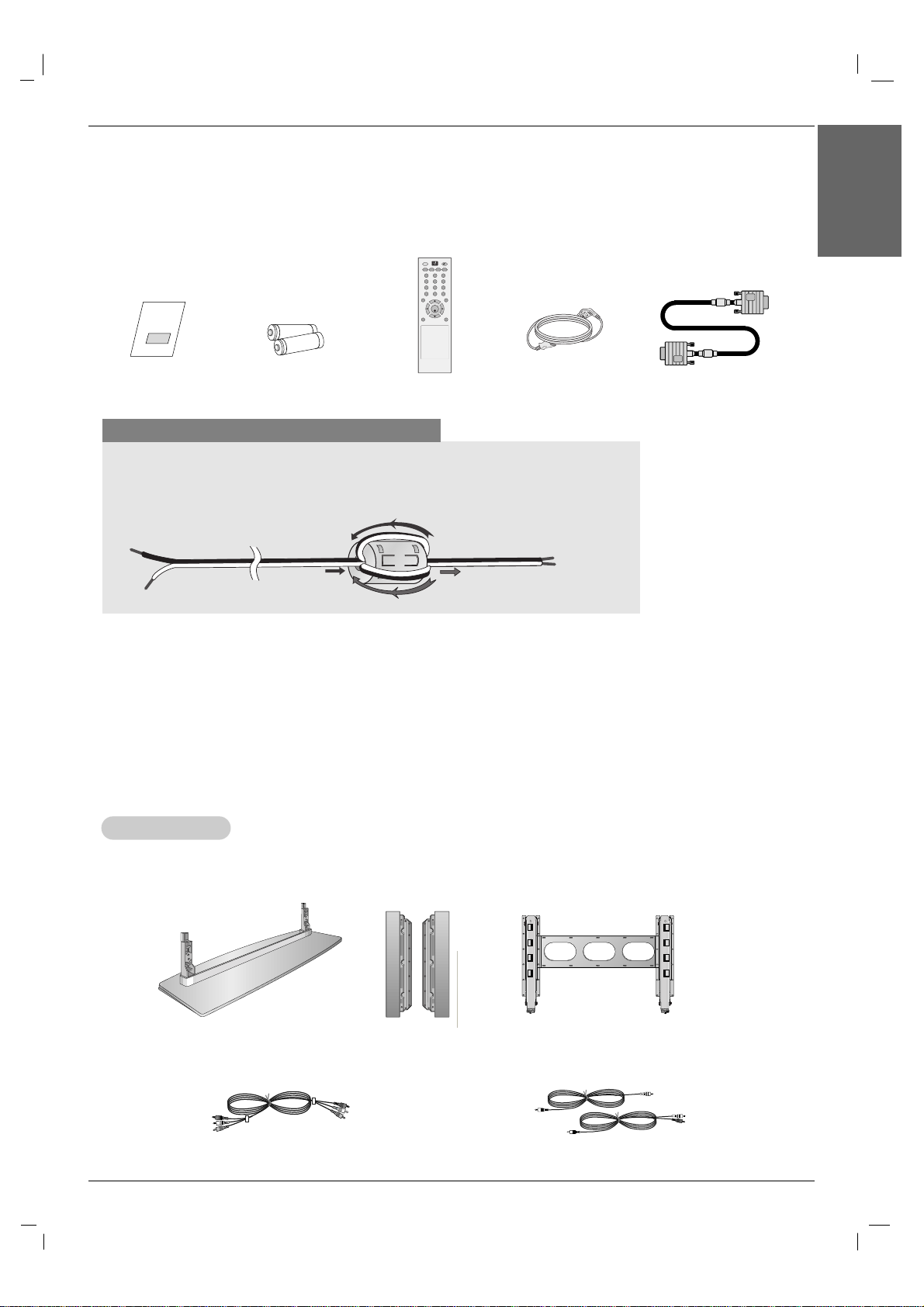
Ensure that the following accessories are included with your plasma display. If an accessory is missing, please contact the dealer
where you purchased the product.
Video cables
Audio cables
- Optional extras can be changed or modified for quality improvement without any notification new optional extras can be added.
- Contract your dealer for buying these items.
Option Extras
Option Extras
Desktop stand speaker
Owner’s Manual 7
Introduction
ENGLISH
Accessories
Accessories
Use the ferrite core with the speaker cables
The ferrite core given as a bundled accessory can be used to reduce the electromagnetic
waves in the connection to the speakers.
Wind the speaker cable on the ferrite core twice, and then plug the cables into the monitor
and the speakers as shown in the following picture:
Owner’s Manual
1.5V
1.5V
Batteries
Power Cord
AV
SLEEP PSM ARC AUTO
MENU EXIT
MUTE
*
POWER
1 2 3
4 5 6
7 8 9
0
INPUT
SET
Remote Control
D-sub 15 pin Cable
Tilt wall mounting bracket
8 Plasma Monitor
Introduction
Controls
Controls
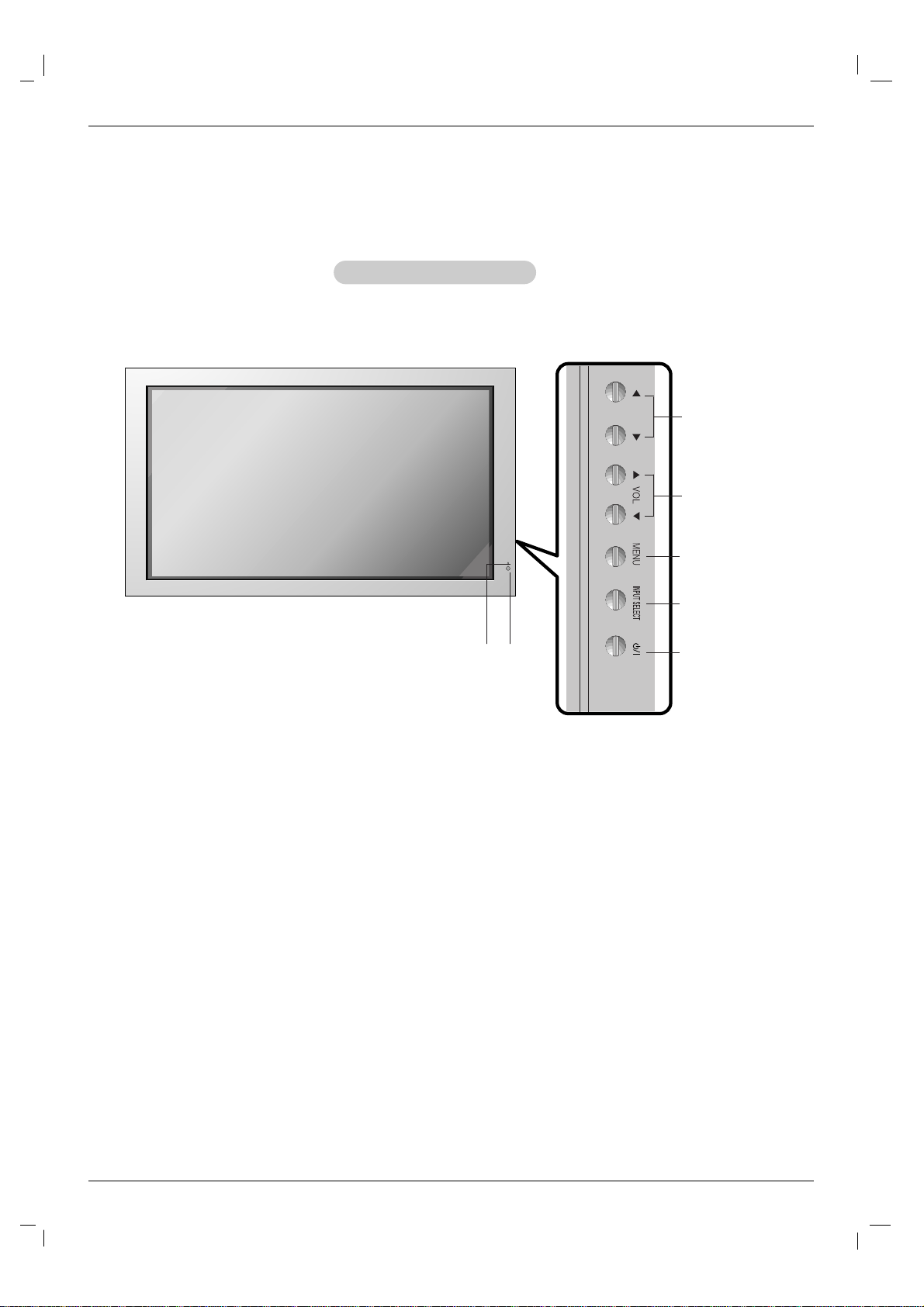
Front Panel Controls
Front Panel Controls
- Here shown may be somewhat different from your set.
1.Power Standby Indicator
Illuminates red in standby mode, Illuminates green when the
Set is turned on.
2. Remote Control Sensor
3. VOLUME (
FF ,GG
) Buttons
4.
EE, DD
Buttons
5. MENU Button
6. INPUT SELECT Button
7. Main Power Button
Switches the set on from standby or off to standby.
2
1
3
4
5
6
7
Owner’s Manual 9
Introduction
ENGLISH
Connection Options
Connection Options
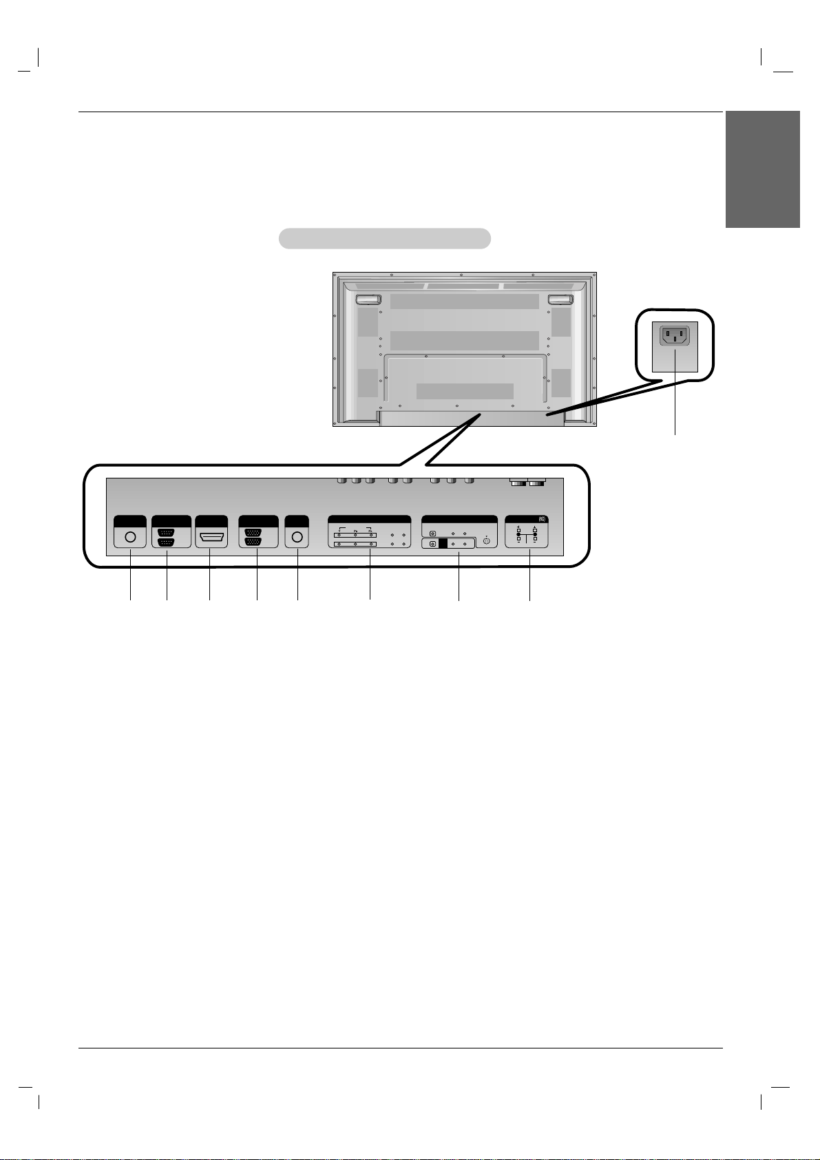
Back Connection Panel
Back Connection Panel
- Here shown may be somewhat different from your set.
REMOTE
CONTROL IN
AUDIO
(RGB/DVI)
HDMI/DVI IN
R
L
RS-232C
(CONTROL/SERVICE)
OUT
IN
RGB
OUT
IN
COMPONENT IN
VIDEO
2
1
L-AUDIO-R
L-AUDIO-R
S-VIDEO
AV IN
VIDEO
AV
OUT
EXTERNAL SPEAKER
1
5
2 3
7
8
9
1. REMOTE CONTROL IN
2. RS-232C INPUT(CONTROL/SERVICE) PORT
Connect to the RS-232C port on a PC.
3. HDMI/DVI IN
Connect a HDMI signal to this jack. Or connect a DVI(Video)
signal.
4. RGB INPUT
Connect the set output connector from a PC to the
appropriate input port.
RGB OUTPUT
You can watch the RGB signal on another set, connect RGB
OUTPUT to another set’s PC input port.
5. AUDIO (RGB/DVI)
Connect the monitor output from a PC to the appropriate
input port.
6. COMPONENT INPUT 1-2
Connect a component video/audio device to these jacks.
7. AV IN
S-VIDEO/AUDIO IN SOCKETS
Connect the S-VIDEO out socket of an VCR to the S-VIDEO
socket.
Connect the audio out sockets of the VCR to the audio sockets as in AV.
8. EXTERNAL SPEAKER (8 ohm output)
Connect to optional external speaker(s).
* For further information, refer to ‘Speaker & Speaker
Stand’ manual.
9. POWER CORD SOCKET
This set operates on an AC power. The voltage is indicated on
the Specifications page. Never attempt to operate the set on
DC power.
4
6
10 Plasma Monitor
Introduction
- When using the remote control, aim it at the remote control sensor on the monitor.
- Under certain conditions such as if the remote IR signal is interrupted, the remote control may not function. Press
the key again as necessary.
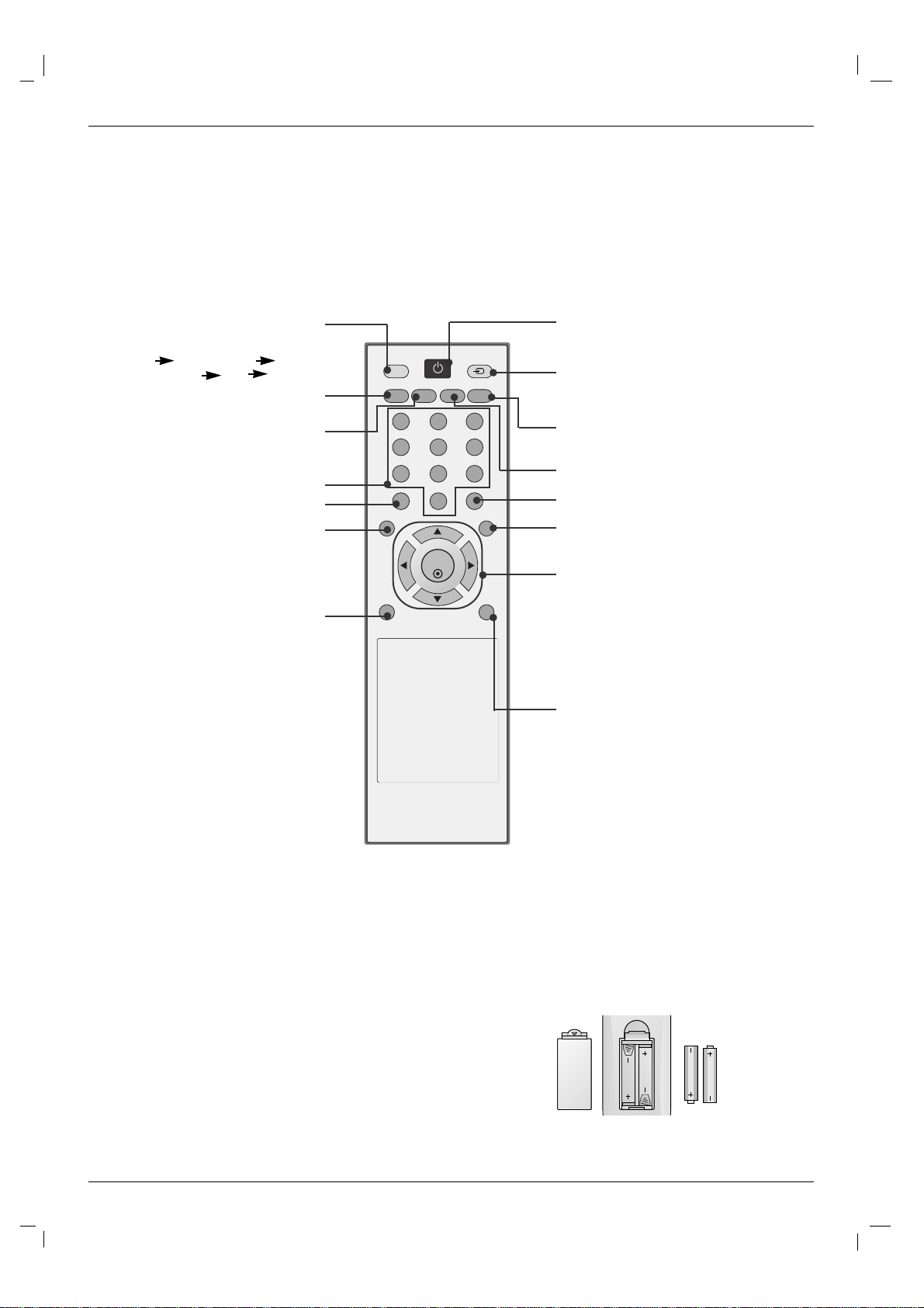
Remote Control Key Functions
Remote Control Key Functions
Installing Batteries
• Open the battery compartment cover on the back side and install the batteries matching correct polarity (+ with +, - with -).
• Install two 1.5V AAAbatteries. Don’t mix old or used batteries with new
ones. Replace cover.
AV
SLEEP PSM ARC AUTO
MENU EXIT
MUTE
*
POWER
1 2 3
4 5 6
7 8 9
0
INPUT
SET
POWER
switches the set on from standby or off to
standby.
INPUT
Selects the TV, AV, Component, RGB or
HDMI modes.
switches the set on from standby.
EXIT
Clears all on-screen displays and returns
to TV viewing from any menu.
There is not a function which is supported.
SET
accepts your selection or displays the
current mode.
FF/ GG
Volume Up/Down
DD/ EE
Adjusts menu settings.
Selects menu item.
*
: No function
AUTO
Automatic adjustment function.
(Operational for the analog signal only)
ARC
Changes the picture format.
NUMBER buttons
There is not a function which is supported.
MENU
Displays on screen menus one by
one.
Exits the current menu.
Memorizes menu changes.
MUTE
Switches the sound on or off.
SLEEP
Sets the sleep timer.
PSM
Adjusts the factory preset picture
according to the room.
AV buttons
Each time you press the lnput
button it will change to
AV1 Component1
Component2 RGB HDMI/DVI.
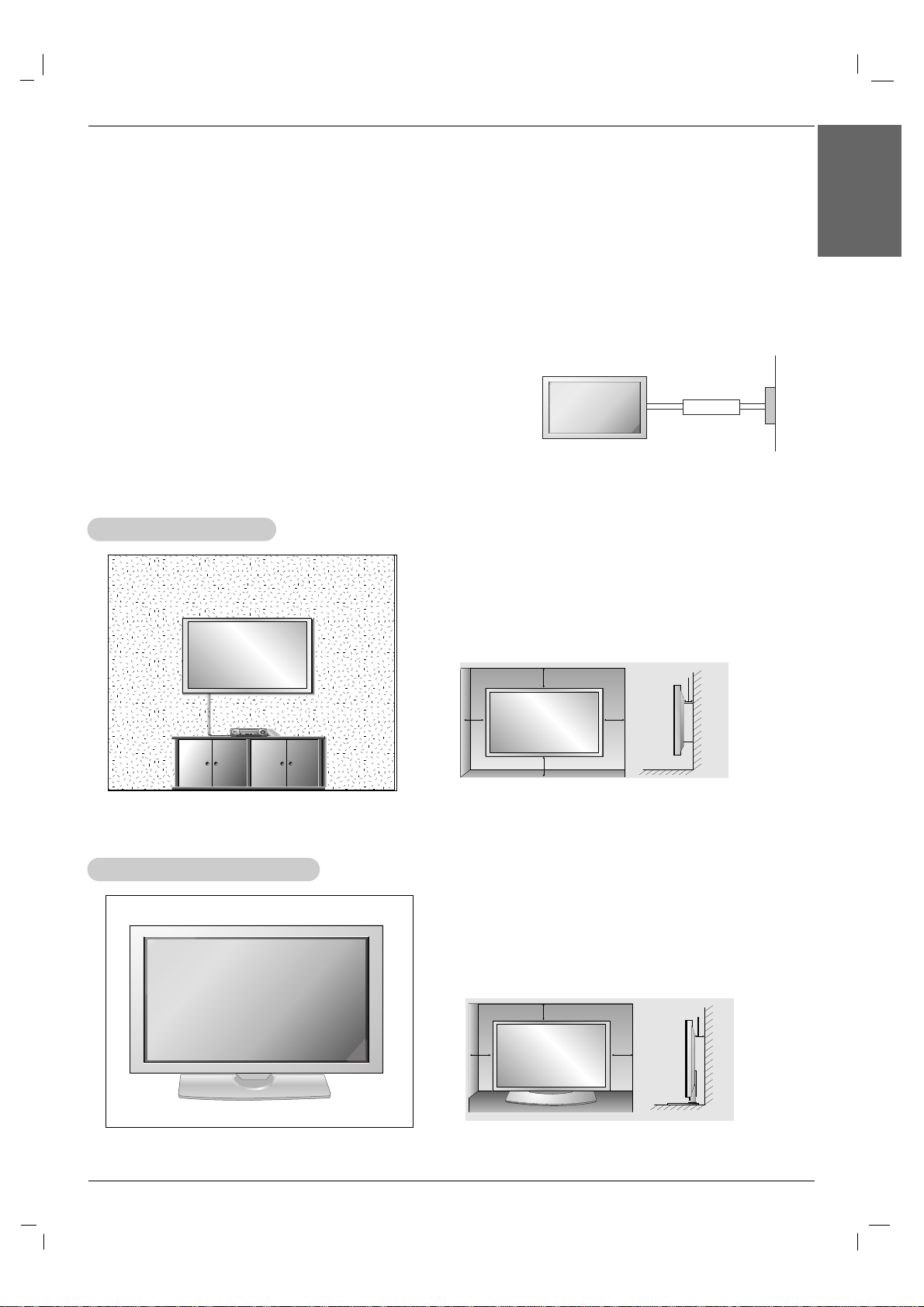
WWall Mount Installation
all Mount Installation
For proper ventilation, allow a clearance of 4” on each
side and 4” from the wall. Detailed installation instructions are available from your dealer, see the optional
Wall Mounting Bracket Installation and Setup Guide.
• Install this monitor only in a location where adequate ventilation is available.
GROUNDING
Ensure that you connect the grounding / earth wire to prevent possible
electric shock. If grounding methods are not possible, have a qualified
electrician install a separate circuit breaker. Do not try to ground the
unit by connecting it to telephone wires, lightening rods, or gas pipes.
Power
Supply
Short-circuit
Breaker
Desktop Pedestal Installation
Desktop Pedestal Installation
For proper ventilation, allow a clearance of 4” on each
side and the top and 4” from the wall. Detailed installation instructions are included in the optional Desktop
Stand Installation and Setup Guide available from your
dealer.
Installation
Installation
Installation Instructions
Installation Instructions
Owner’s Manual 11
Installation
ENGLISH
4 inches
4 inches
4 inches
4 inches4 inches
4 inches
4 inches
4 inches
4 inches
12 Plasma Monitor
Installation
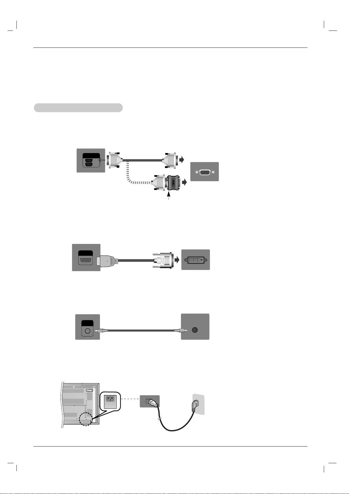
External Equipment Connections
External Equipment Connections
NOTE: Not all cables shown are included with the plasma display.
1. First of all, see if the computer, product and the peripherals are turned off.
Then, connect the signal input cable.
2. Connect the Audio cable.
a. When connecting with the D-Sub signal input cable.
When Connecting to your PC
When Connecting to your PC
RGB
OUT
IN
Rear side of the product.
PC
PC
MAC
b. When connecting with the HDMI to DVI signal input cable (not included).
HDMI/DVI IN
Rear side of the product.
PC
AUDIO
(RGB/DVI)
Rear side of the product.
3. Connect the power cord.
(not included)
PC/MAC
Macintosh Adapter (not included)
Use the standard Macintosh adapter since an incompatible
adapter is available in the market. (Different signaling system)
Owner’s Manual 13
Installation
ENGLISH
4. Turn on power by pressing the power button on the product.
Turn on the PC.
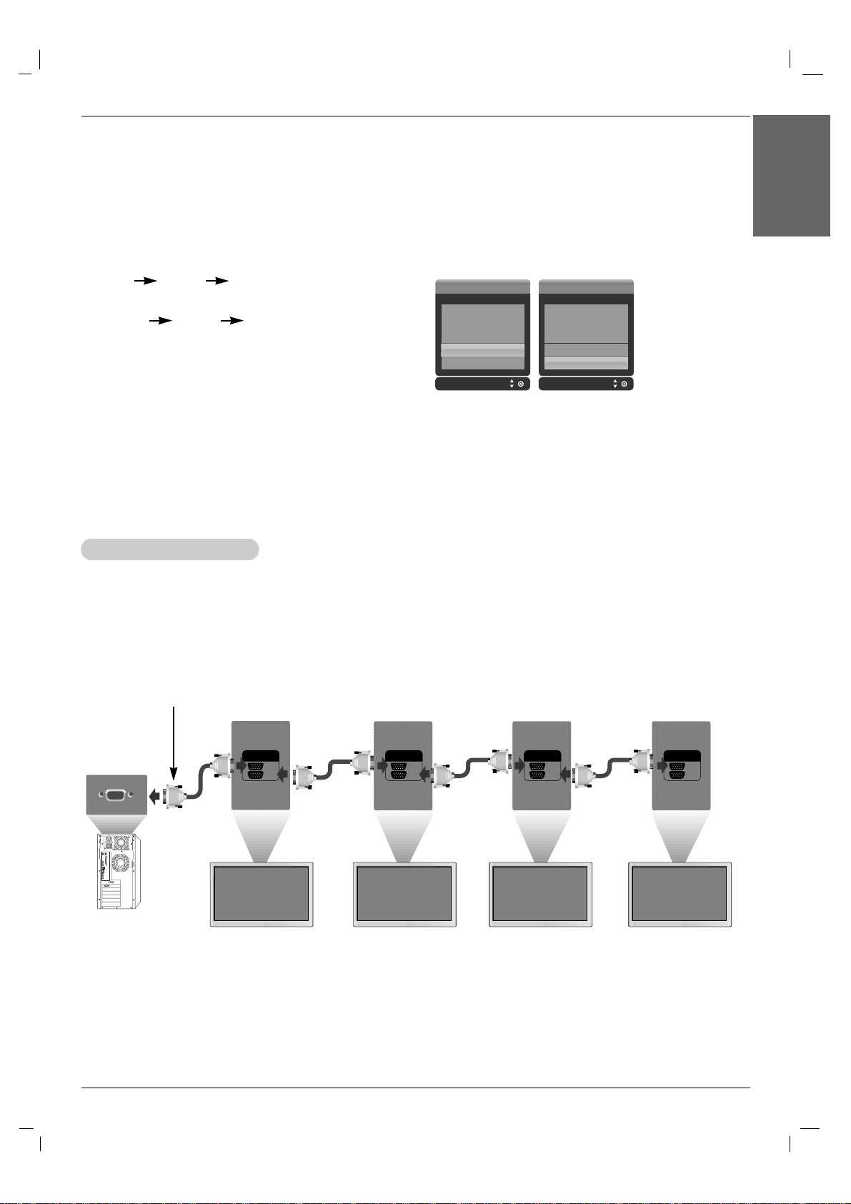
Use this function when displaying ANALOG RGB inputs of a PC to the other product.
• To use different products connected to each other Connect one end of the signal input cable(15-pin
D-Sub Signal Cable) to the RGB OUT connector of product 1 and connect the other end to the RGB IN
connector of other products.
5. Select an input signal.
Press the INPUT button on the remote control to select the input
signal.
INPUT
DD/ EE
SET
Or, press the SOURCE button on the back of the product.
SOURCE
DD/ EE
AUTO/SET
a. When connecting with a D-Sub signal input cable.
• Select RGB : 15-pin D-Sub analog signal.
b. When connecting with a HDMI to DVI signal input cable.
• Select HDMI/DVI : HDMI to DVI Digital signal.
Input Input
AV
Component1
Component2
RGB
HDMI/DVIA
AV
Component1
Component2
RGB
HDMI/DVI
NOTES: • How to connect to two computers.
Connect the signal cables (HDMI to DVI and D-Sub) to each computer.
Press the INPUT button on the remote control to select the computer to use.
• Directly connect to a grounded power outlet on the wall or a power bar with a ground wire.
NOTES: • When multi-connecting in/out cascade format, cables to be less damaged are recommended.
We recommend that you should use cable distributor.
WWatching RGB Outputs
atching RGB Outputs
RGB
OUT
IN
RGB
OUT
IN
RGB
OUT
IN
RGB
OUT
IN
15-pin D-Sub Signal Cable
PC
Product 1 Product 2 Product 3 Product 4
 Loading...