

LG 50PK250-ZA, 42PJ350N-ZA, 50PK250N-ZA, 60PK250-ZA, 60PK250N-ZA Owner's Manual
...
www.lg.com
OWNER’S MANUAL
PLASMA TV
Please read this manual carefully before operating
your set and retain it for future reference.
ENGLISH
Downloaded From TV-Manual.com Manuals

HDMI, the HDMI logo and High-Definition Multimedia Interface
are trademarks or registered trademarks of HDMI Licensing LLC.
Downloaded From TV-Manual.com Manuals
I
CONTENTS
CONTENTS
PREPARATION
42/50PJ2**, 42/50PJ3**, 42/50PJ5**,
42/50PJ6**, 50/60PK2**,50PK3**, 50/60PK5**,
50PK7**.................................................................. A-1
EXTERNAL EQUIPMENT SETUP
Antenna Connection..................................................1
Connecting with a Component cable................... 2
Connecting with an HDMI cable ........................... 3
Connecting with an HDMI to DVI cable .............. 3
Connecting with a Euro Scart cable.......................4
Usb setup .....................................................................4
Connecting with a RCA cable..................................5
Connecting with a RF Cable.....................................5
Connecting with a D-sub 15 pin cable..................6
Insertion of CI Module ..............................................6
Digital audio out Setup.............................................7
Supported Display Resolution.................................8
Screen Setup for PC mode.....................................10
WATCHING TV / PROGRAMME CONTROL
Turning on the TV ................................................... 14
Initializing setup .......................................................14
Programme Selection ............................................. 14
Volume Adjustment ................................................ 14
Quick Menu ............................................................. 15
On-Screen Menus Selection and Adjustment... 16
Auto Programme Tuning......................................... 17
Manual Programme Tuning (In Digital Mode).. 20
Manual Programme Tuning (In Analogue Mode).. 22
Programme Edit ....................................................... 24
Software Update...................................................... 26
Diagnostics............................................................... 28
CI Information.......................................................... 29
Selecting the Programme List .............................. 30
Favourite Programme Setup .................................. 31
Input List................................................................... 32
Data Service...............................................................33
Input Label.................................................................33
Simple manual.......................................................... 34
............................................................. 35
AV Mode ................................................................... 38
Initializing (Reset to original factory settings) ..39
TO USE A BLUETOOTH
Precautions when using the Bluetooth.............. 40
Setting the Bluetooth............................................. 41
Set TV PIN .................................................................42
Bluetooth headset
- Connecting a new Bluetooth headset...........43
- Connecting to Bluetooth headset already
registered......................................................... 43
- Disconnecting the Bluetooth headset during
use............................................................................44
- When requesting to connect to TV from the
Bluetooth headset................................................44
Managing Registered Bluetooth device ............. 45
My Bluetooth Information......................................46
Receiving Photos from external Bluetooth device .........47
Listening to the Musics from external Bluetooth
device..........................................................................47
TO USE A USB DEVICE
When connecting a USB device .......................... 48
Photo List.................................................................. 49
Music List ...................................................................55
Movie List...................................................................60
DivX Registration Code ..........................................66
Deactivation ..............................................................67
Downloaded From TV-Manual.com Manuals

II
CONTENTS
CONTENTS
EPG (ELECTRONIC PROGRAMME
GUIDE) (IN DIGITAL MODE)
Switch on/off EPG .................................................. 68
Select a Programme................................................ 68
Button Function in NOW/NEXT Guide Mode . 68
Button Function in 8 Day Guide Mode...............69
Button Function in Date Change Mode............. 69
Button Function in Extended Description Box .. 70
Button Function in Record/Remind Setting Mode....... 70
Button Function in Schedule List Mode............. 70
PICTURE CONTROL
Picture Size (Aspect Ratio) Control ................... 71
Picture Wizard ...........................................................73
Energy Saving ............................................................74
Preset Picture Settings
- Picture Mode-Preset........................................ 75
Manual Picture Adjustment
- Picture Mode-User option ............................. 76
Picture Improvement Technology........................ 77
Expert Picture Control........................................... 78
Picture Reset ............................................................ 81
Image Sticking Minimization(ISM) Method........82
Demo Mode ............................................................. 83
Mode Setting.............................................................84
SOUND & LANGUAGE CONTROL
Auto Volume Leveler............................................... 85
Clear Voice II .............................................................86
Preset Sound Settings - Sound Mode................ 87
Sound Setting Adjustment -User Mode..............88
Infinite Sound........................................................... 88
Balance...................................................................... 89
TV Speakers On/ Off Setup..................................90
DTV Audio setting (In Digital Mode only)........91
Selecting Digital Audio Out...................................92
Audio Reset ...............................................................93
Audio Description (In Digital Mode only) .........94
I/II
- Stereo/Dual Reception (In Analogue Mode
Only) ...................................................................... 95
- NICAM Reception (In Analogue Mode Only).... 96
- Speaker Sound Output Selection................. 96
On-Screen Menu Language/Country Selection.. 97
Language Selection (In Digital Mode only)...... 98
TIME SETTING
Clock Setup.............................................................. 99
Auto On/ Off Time Setting ................................ 100
Sleep Timer Setting .............................................. 101
PARENTAL CONTROL / RATINGS
Set Password & Lock System............................. 102
Block Programme .................................................. 103
Parental Control (In Digital Mode only) ......... 104
External Input Blocking.........................................105
Key Lock.................................................................. 106
TELETEXT
Switch on/off ......................................................... 107
SIMPLE Text............................................................ 107
TOP Text ................................................................. 107
FASTEXT ................................................................. 108
Special Teletext Functions .................................. 108
DIGITAL TELETEXT
Teletext within Digital Service............................ 109
Teletext in Digital Service.................................... 109
APPENDIX
Troubleshooting ..................................................... 110
Maintenance .......................................................... 112
Product Specifications.......................................... 113
IR Codes .................................................................. 115
External Control Device Setup ........................... 116
Downloaded From TV-Manual.com Manuals
A-1
PREPARATION
PREPARATION
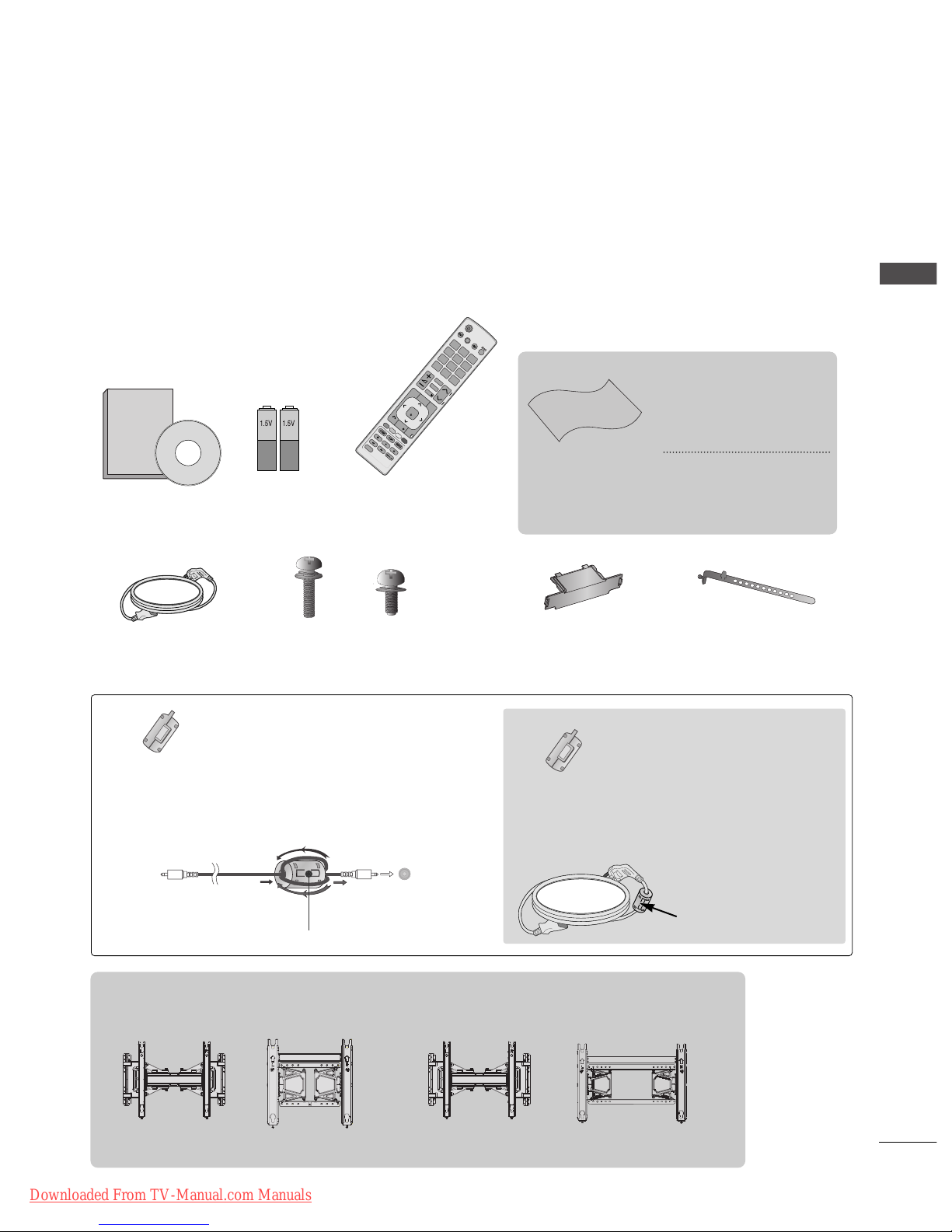
ACCESSORIES
PPLLAASSMMAA TTVV MMooddeellss :: 4422//5500PPJJ22
**** ,,
4422//5500PPJJ33
**** ,,
4422//5500PPJJ55
**** ,,
4422//5500PPJJ66
**** ,,
5500//6600PPKK22
**** ,,
5500 PPKK33
**** ,,
5500//6600PPKK55
**** ,,
5500 PPKK77
** **
Ensure that the following accessories are included with your TV. If an accessory is missing, please contact the
dealer where you purchased the TV.
■
Image shown may differ from your TV.
Batteries
(AAA)
Remote Control
Power Cord
P
A
G
E
P
123
45
0
6
789
LIST
Q.VIEW
AV MODE
INPUT
TV/
RAD
ENERGY
SAVING
MARK
FAV
RATIO
MUTE
MENU
GUIDE
Q.MENU
BACK
INFO
EXIT
OK
FREEZE
A
D
Protection
Cover
x 4
Cable Holder
x 2
x 3
M4x28
M5x14
(Except for 60PK5**, 60PK2**)
Wall Mounting Bracket
(Separate purchase)
(Only 60PK5**, 60PK2**)
(Except for 60PK2**, 60PK5**)
Bolts for stand assembly
Polishing Cloth
Polishing cloth for use
on the screen.
This item is not included for all models.
* Lightly wipe any stains
or fingerprints on the
surface of the TV with
the polishing cloth.
Do not use excessive
force. This may cause
scratching or discolouration.
Ferrite Core
(Black)
(This feature is not
available for all
models.)
Ferrite core can be used to reduce
the electromagnetic wave when
connecting the power cord.
The closer the location of the ferrite core to the power plug, the
better it is.
The ferrite core can be used to reduce the
electromagnetic waves in the PC Audio
cable.
Wind the PC Audio cable on the ferrite core
twice, and then plug the cables into the TV
as shown in the following picture.
Place the ferrite core close to AUDIO
IN(RGB/DVI) jack on the display.
Place the ferrite core close to
AUDIO IN(RGB/DVI) jack on the display.
Ferrite Core
(Gray)
(This feature is not
available for all
models.)
AUDIO IN
(RGB/DVI)
Install the power plug
closely.
AW-50PG60MS AW-50PG60M AW-60PG60M
AW-60PG60MS
or
or
Owner's
Manual
Owner’s Manual
Downloaded From TV-Manual.com Manuals
A-2
PREPARATION
PREPARATION
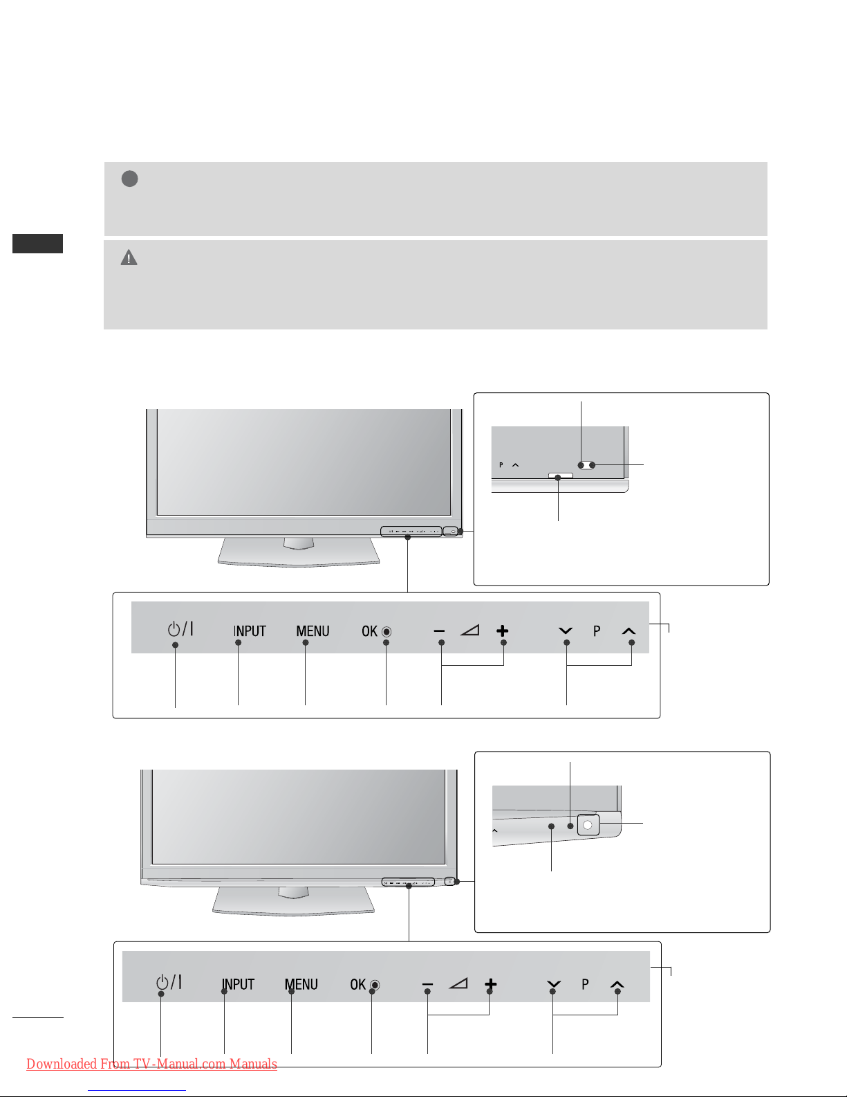
FRONT PANEL CONTROLS
■
Image shown may differ from your TV.
G
Do not step on the glass stand or subject it to any impact.
It may break, causing possible injury from fragments of glass, or the TV may fall.
G
Do not drag the TV. The floor or the product may be damaged.
CAUTION
NOTE
!
G
The energy consumed during use can be significantly reduced if the level of brightness of the picture is
reduced, and this will reduce the overall running cost.
INPUT MENU
OK VOLUME
PROGRAMME
POWER
Power/Standby Indicator
•
Illuminates red in standby mode.
• Turn off red smoothly when the TV is switched on.
Intelligent Sensor
Adjusts picture according
to the surround-
ing conditions
42/50PJ2
**,
50/60PK2
**
Remote Control Sensor
INPUT MENU
OK VOLUME
PROGRAMME
POWER
Power/Standby Indicator
•
Illuminates red in standby mode.
• Turn off red smoothly when the TV is switched on.
Intelligent Sensor
Adjusts picture according
to the surround-
ing conditions
42/50PJ3
**,
50PK3
**
Remote Control Sensor
Touch Sensor
You can use the desired button function by touching.
Touch Sensor
You can use the desired button function by touching.
Downloaded From TV-Manual.com Manuals
A-3
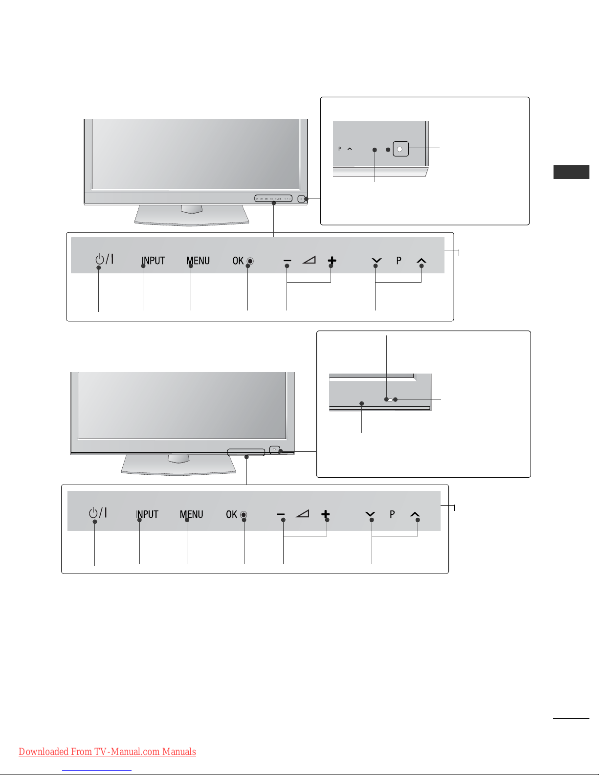
PREPARATION
INPUT MENU
OK VOLUME
PROGRAMME
POWER
Power/Standby Indicator
•
Illuminates red in standby mode.
• Turn off red smoothly when the TV is switched on.
Intelligent Sensor
Adjusts picture according
to the surround-
ing conditions
42/50PJ5
**,
50/60PK5
**
Remote Control Sensor
INPUT MENU
OK VOLUME
PROGRAMME
POWER
Power/Standby Indicator
•
Illuminates red in standby mode.
• Turn off red smoothly when the TV is switched on.
Intelligent Sensor
Adjusts picture according
to the
surrounding conditions
Remote Control Sensor
42/50PJ6
**,
50PK7
**
Touch Sensor
You can use the desired button function by touching.
Touch Sensor
You can use the desired button function by touching.
Downloaded From TV-Manual.com Manuals
A-4
PREPARATION
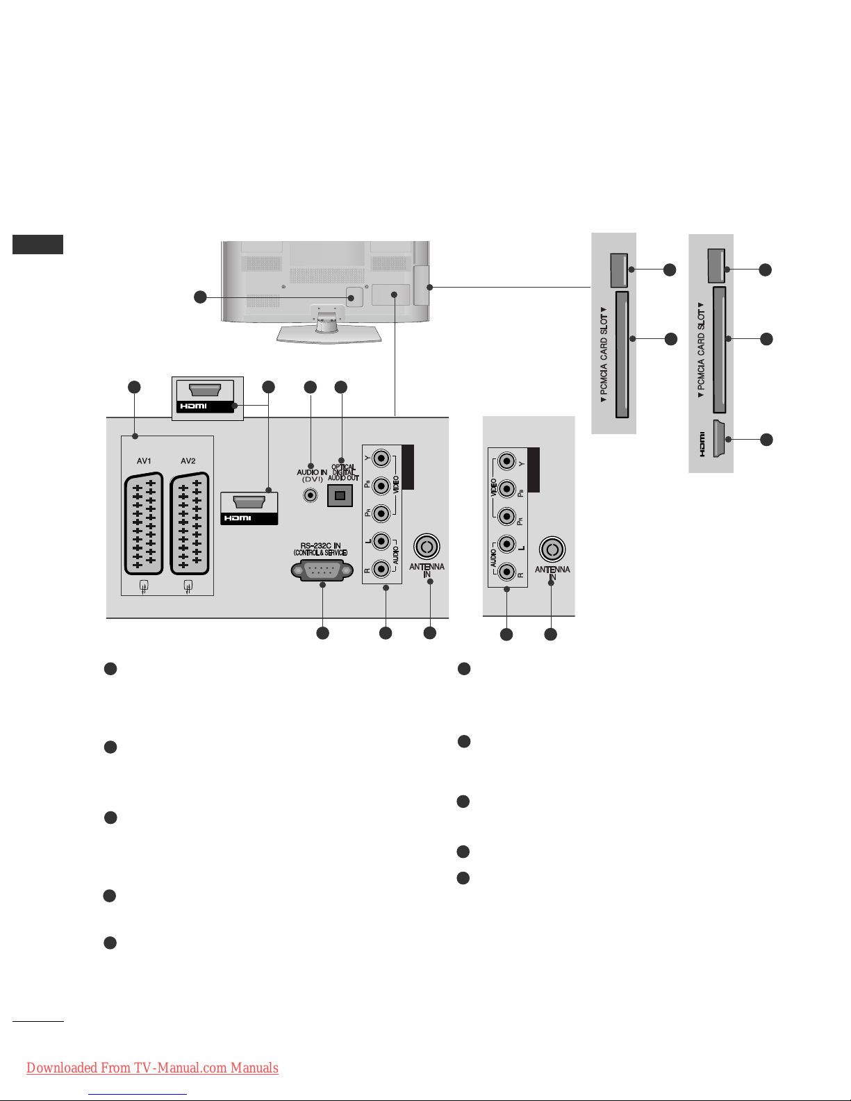
BACK PANEL INFORMATION
■
Image shown may differ from your TV.
Power Cord Socket
This TV operates on an AC power. The voltage is
indicated on the Specifications page. (
GG
p.113 t o
114
) Never attempt to operate the TV on DC power.
Euro Scart Socket (AV1/AV2)
Connect scart socket input or output from an
external device to these jacks.
HDMI/DVI IN Input
Connect an HDMI signal to HDMI IN. Or DVI
(VIDEO) signal to HDMI/DVI port with DVI to
HDMI cable.
DVI Audio Input
Connect the audio from a DVI.
OPTICAL DIGITAL AUDIO OUT
Connect digital audio to various types of equipment.
Connect to a Digital Audio Component.
Use an Optical audio cable.
RS-232C IN (CONTROL & SERVICE) PORT
Connect to the RS-232C port on a PC.
This port is used for Service or Hotel mode.
Component Input
Connect a component video/audio device to
these jacks.
Antenna Input
Connect antenna or cable to this jack.
SERVICE ONLY PORT
PCMCIA (Personal Computer Memory Card
International Association) Card Slot
Insert the CI Module to
PPCC MM CC II AA CC AARRDD SSLLOOTT..
(This feature is not available in all countries.)
1
2
3
4
5
7
6
8
9
10
L/MONO
R
AUDIO
S-VIDEO
USB IN
SERVICE ONLY
IN 2
1
SERSERVICEVICE
ONLY
SERVICE
ONL
Y
SERVICEVICE
ONLY
IN 2
42/50PJ2**, 50/60PK2
**
COMPONENT IN
SERVICE
ONLY
SERVICE
ONL
Y
COMPONENT INCOMPONENT IN
IN 2
(Only 50/60PK2**)
SERVICE
ONLY
SERVICE
ONL
Y
/DVI IN
COMPONENT INCOMPONENT IN
IN 2
2 4 5
76
8
7
8
SERVICE
ONL
Y
COMPONENT IN
/DVI IN1
COMPONENT IN
IN 2
(Only 42/50PJ2**)
(Only 50/60PK2**)
9
10
9
10
3
3
or
Downloaded From TV-Manual.com Manuals
A-5
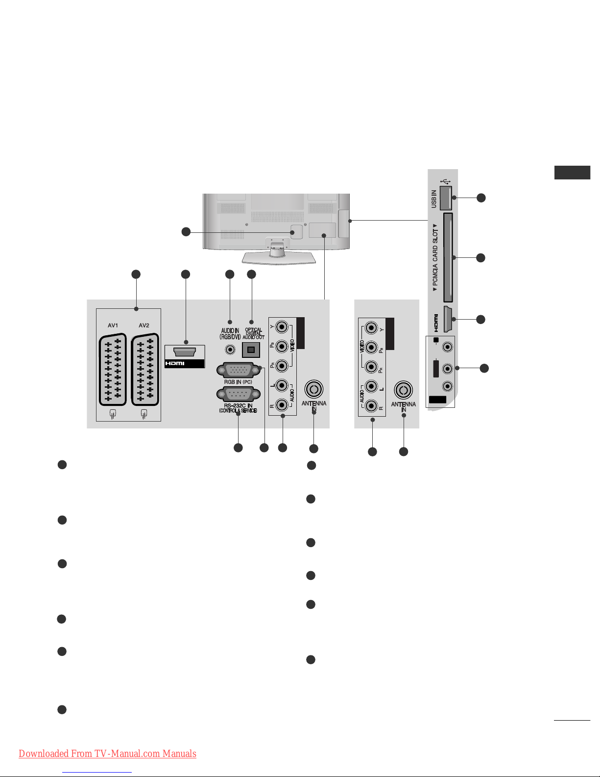
PREPARATION
Power Cord Socket
This TV operates on an AC power. The voltage is
indicated on the Specifications page. (
GG
p.113 t o
114
) Never attempt to operate the TV on DC power.
Euro Scart Socket (AV1/AV2)
Connect scart socket input or output from an
external device to these jacks.
HDMI/DVI IN Input
Connect an HDMI signal to HDMI IN. Or DVI
(VIDEO) signal to HDMI/DVI port with DVI to
HDMI cable.
RGB/DVI Audio Input
Connect the audio from a PC or DVI.
OPTICAL DIGITAL AUDIO OUT
Connect digital audio to various types of equipment.
Connect to a Digital Audio Component.
Use an Optical audio cable.
RS-232C IN (CONTROL & SERVICE) PORT
Connect to the RS-232C port on a PC.
This port is used for Service or Hotel mode.
RGB IN Input
Connect the output from a PC.
Component Input
Connect a component video/audio device to
these jacks.
Antenna Input
Connect antenna or cable to this jack.
USB Input
Connect USB storage device to this jack.
PCMCIA (Personal Computer Memory Card
International Association) Card Slot
Insert the CI Module to
PPCC MM CC II AA CC AARRDD SSLLOOTT..
(This feature is not available in all countries.)
Audio/Video Input
Connect audio/video output from an external
device to these jacks.
1
2
3
4
5
6
7
8
9
10
11
12
L/MONO
R
AUDIO
S-VIDEO
USB IN
SERVICE ONLY
IN 2
1
/DVI IN 1
AV IN 3
L/ MONO
R
AUDIO
VIDEO
S-VIDEO
USB IN
SERVICE ONLY
COMPONENT IN
IN 2
2 43 5
876
AV IN 3
L/MONO
R
AUDIOAUDIO
VIDEOVIDEO
S-VIDEO
USB IN
SERVICE ONLY
IN 2
10
9
11
3
12
42/50PJ3**, 42/50PJ5**, 42/50PJ6**, 50PK3
**
COMPONENT IN
SERVICE
ONLY
SERVICE
ONL
Y
COMPONENT INCOMPONENT IN
IN 2
8
9
or
Downloaded From TV-Manual.com Manuals
L/MONO
R
AUDIO
S-VIDEO
USB IN
SERVICE ONLY
IN 2
A-6
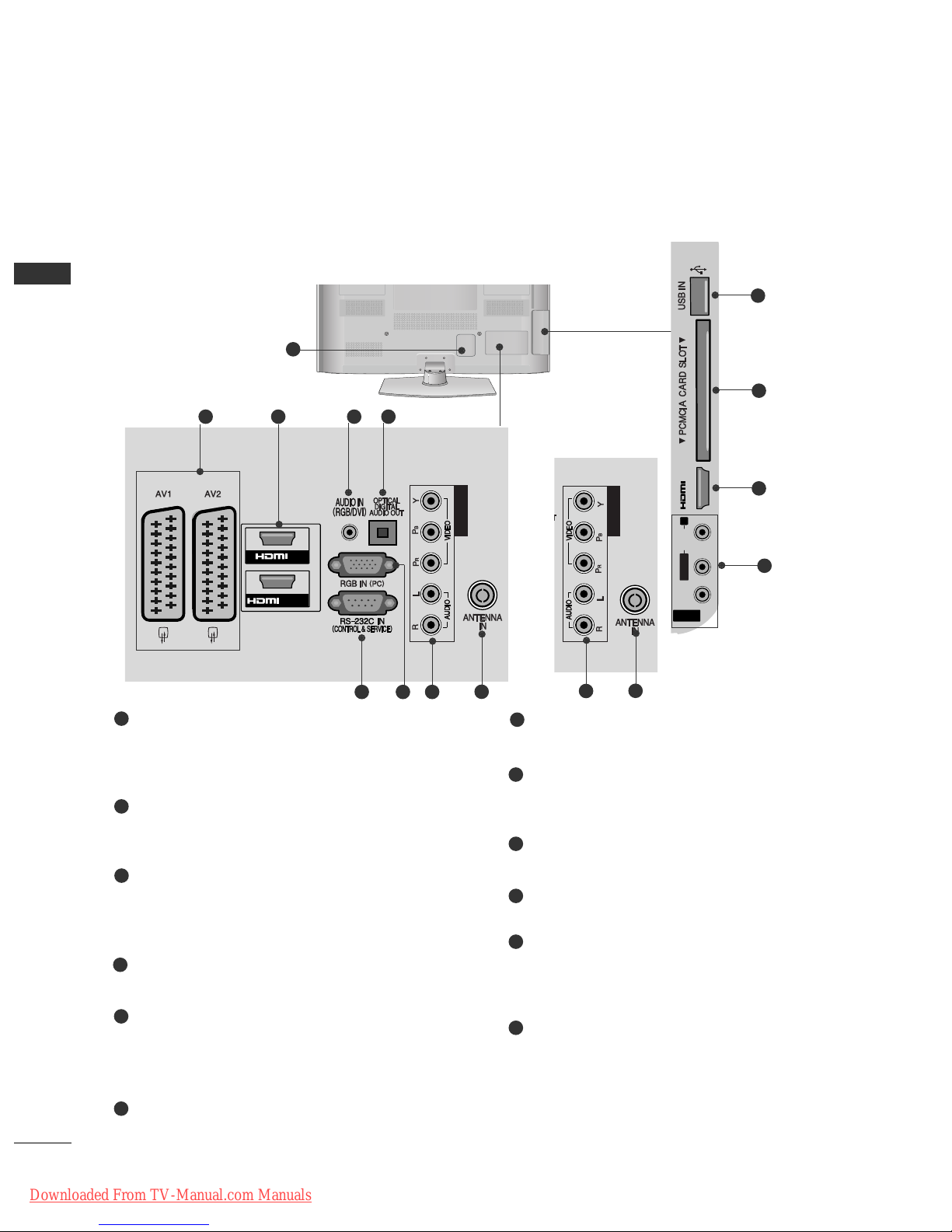
PREPARATION
PREPARATION
Power Cord Socket
This TV operates on an AC power. The voltage is
indicated on the Specifications page. (
GG
p.113 t o
114 ) Never attempt to operate the TV on DC power.
Euro Scart Socket (AV1/AV2)
Connect scart socket input or output from an
external device to these jacks.
HDMI/DVI IN Input
Connect an HDMI signal to HDMI IN. Or DVI
(VIDEO) signal to HDMI/DVI port with DVI to
HDMI cable.
RGB/DVI Audio Input
Connect the audio from a PC or DVI.
OPTICAL DIGITAL AUDIO OUT
Connect digital audio to various types of equipment.
Connect to a Digital Audio Component.
Use an Optical audio cable.
RS-232C IN (CONTROL & SERVICE) PORT
Connect to the RS-232C port on a PC.
This port is used for Service or Hotel mode.
RGB IN Input
Connect the output from a PC.
Component Input
Connect a component video/audio device to
these jacks.
Antenna Input
Connect antenna or cable to this jack.
USB Input
Connect USB storage device to this jack.
PCMCIA (Personal Computer Memory Card
International Association) Card Slot
Insert the CI Module to
PPCC MM CC II AA CC AARRDD SSLLOOTT..
(This feature is not available in all countries.)
Audio/Video Input
Connect audio/video output from an external
device to these jacks.
1
2
3
4
5
6
7
8
9
10
11
12
1
/DVI IN
AV IN 3
L/ MONO
R
AUDIO
VIDEO
S-VIDEO
IN 3
USB IN
SERVICE ONLY
IN
1
2
COMPONENT IN
2 43 5
876
AV IN 3
L/MONO
R
AUDIOAUDIO
VIDEOVIDEO
S-VIDEO
IN 3
USB IN
SERVICE ONLY
10
9
11
3
12
50/60PK5
**,
50PK7
**
COMPONENT IN
SERVICE
ONLY
SERVICE
ONL
Y
COMPONENT INCOMPONENT IN
IN 2
8
9
or
Downloaded From TV-Manual.com Manuals
A-7
PREPARATION
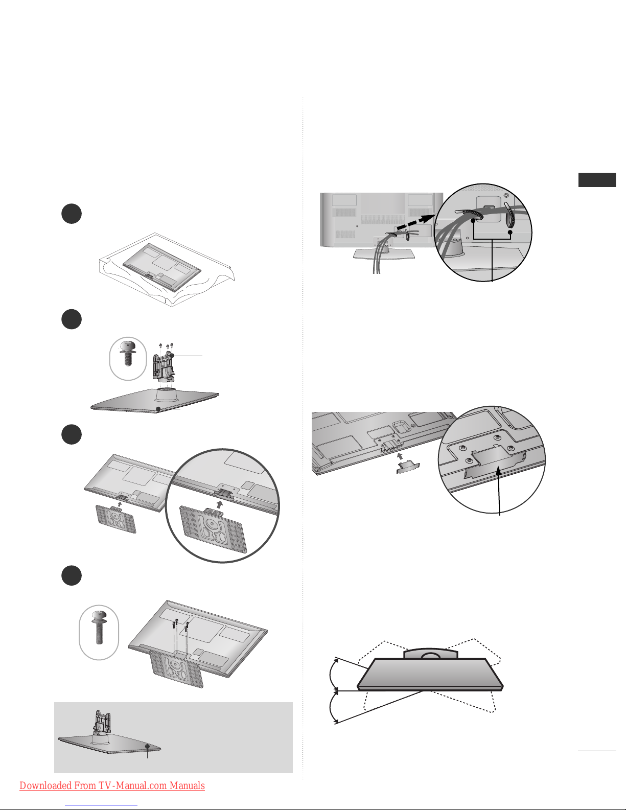
1
3
4
Carefully place the TV screen side down on a cushioned surface to protect the screen from damage.
2
Assemble the parts of the
SSttaa nn dd BB ooddyy
with
the
SSttaa nn dd BB aass ee
of the TV.
Assemble the TV as shown.
Fix the 4 bolts securely using the holes in the
back of the TV.
Stand Body
Stand Base
■
Image shown may differ from your TV
When assembling the desk type stand, check whether
the bolt is fully tightened. (If not tightened fully, the
product can tilt forward after the product installation.)
If you tighten the bolt with excessive force, the bolt can
deviate from abrasion of the tightening part of the bolt.
SWIVEL STAND
■
Image shown may differ from your TV.
After installing the TV, you can adjust the TV set
manually to the left or right direction by 20 degrees
to suit your viewing position.
BACK COVER FOR
WIRE ARRANGEMENT
■
Image shown may differ from your TV.
After Connecting the cables as necessary, install
Cable Holder as shown and bundle the cables.
Cable Holder
■
Image shown may differ from your TV.
When installing the wall-mounted unit, use the protection cover.
NOT USING THE DESKTYPE STAND
Insert the
PPrroott eeccttiioonn
CCoovv eerr
into the TV until click-
ing sound.
Protection Cover
(Fix a Guide to the Outsides.)
M5x14
M4x28
STAND INSTALLATION
(Except for 60PK5**, 60PK2
**
)
Front
When assembling the stand,
make sure to distinguish and
assemble the front and rear
side of the stand correctly.
Downloaded From TV-Manual.com Manuals
A-8
PREPARATION
PREPARATION
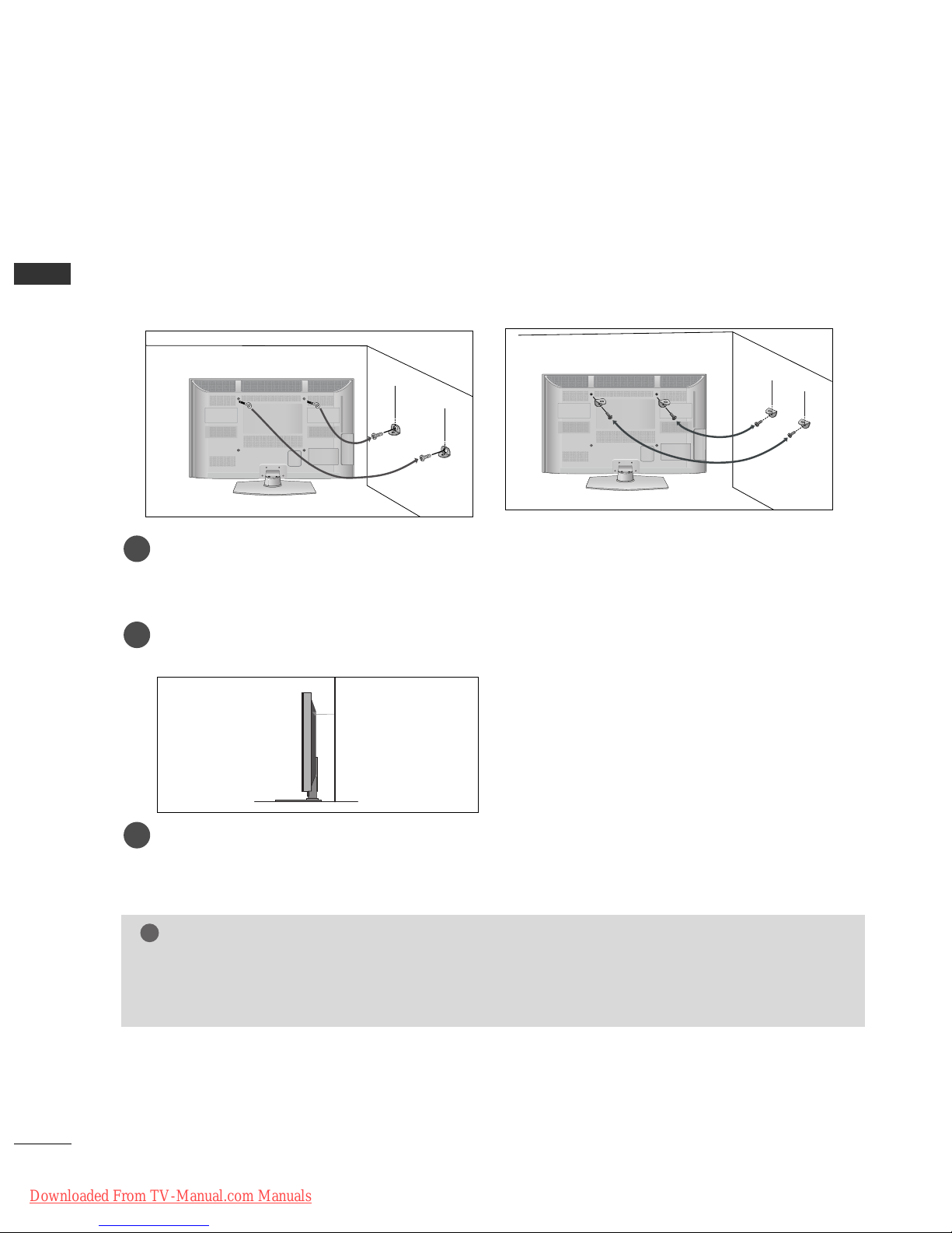
CAREFUL INSTALLATION ADVICE
A
You should purchase necessary components to fix the TV safety and secure to the wall on the market.
A
Position the TV close to the wall to avoid the possibility of it falling when pushed.
A
The instructions shown below are a safer way to set up the TV, by fixing it to the wall, avoiding the possibility of it falling forwards if pulled. This will prevent the TV from falling forward and causing injury. This will
also prevent the TV from damage. Ensure that children do not climb or hang from the TV.
NOTE
!
G
When moving the TV undo the cords first.
G
Use a platform or cabinet strong and large enough to support the size and weight of the TV.
G
To use the TV safely make sure that the height of the bracket on the wall and on the TV is the same.
3
1
2
Use the eye-bolts or TV brackets/bolts to fix the product to the wall as shown in the picture.
(If your TV has bolts in the eyebolts, loosen then bolts.)
* Insert the eye-bolts or TV brackets/bolts and tighten them securely in the upper holes.
Secure the wall brackets with the bolts on the wall. Match the height of the bracket that is mounted on
the wall.
3
Use a sturdy rope to tie the product for alignment. It is safer to tie the rope so it becomes horizontal
between the wall and the product.
2
1
2
1
Downloaded From TV-Manual.com Manuals
A-9
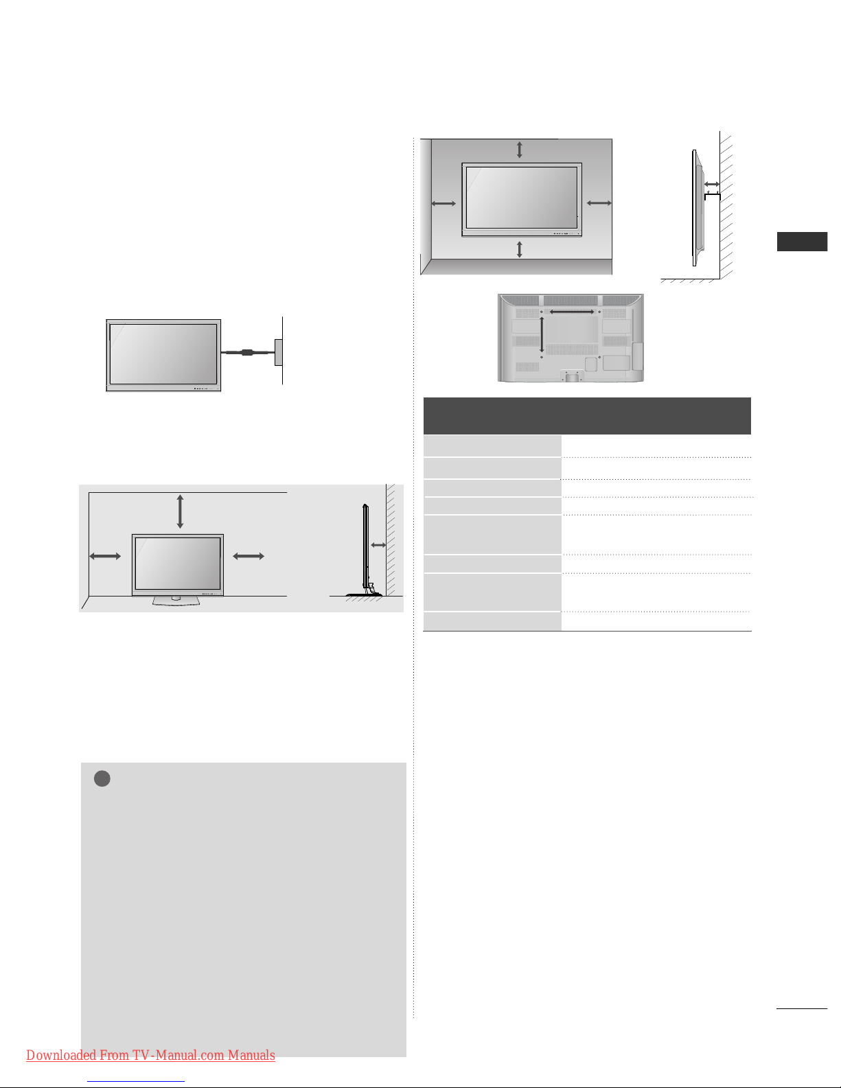
PREPARATION
10 cm
Model
VESA
(A *B)
Standard
Screw
Quantity
42/50PJ2
**
42/50PJ3
**
42/50PJ5
**
42/50PJ6
**
50PK2
**
60PK2
**
50PK3
**
50PK5
**
60PK5
**
50PK7
**
400 * 400
400 * 400
400 * 400
400 * 400
400 * 400
600 * 400
400 * 400
400 * 400
600 * 400
400 * 400
M6
M6
M6
M6
M6
M8
M6
M6
M8
M6
4
4
4
4
4
4
4
4
4
4
A
The TV can be installed in various ways such as on
a wall, or on a desktop etc.
A
The TV is designed to be mounted horizontally.
Power Supply
Circuit breaker
EARTHING
Ensure that you connect the earth wire to prevent
possible electric shock. If grounding methods are not
possible, have a qualified electrician install a separate
circuit breaker.
Do not try to earth the TV by connecting it to telephone wires, lightening rods or gas pipes.
WALL MOUNT: HORIZONTAL
INSTALLATION
A
We recommend the use of a LG Brand wall mounting
bracket when mounting the TV to a wall.
A
We recommend that you purchase a wall mounting
bracket which supports VESA standard.
A
LG recommends that wall mounting be performed
by a qualified professional installer.
10 cm
10 cm
10 cm
NOTE
!
G Should Install wall mount on a solid wall perpen-
dicular to the floor.
G Should use a special wall mount, if you want to
install it to ceiling or slanted wall.
G The surface that wall mount is to be mounted on
should be of sufficient strength to support the
weight of TV set; e.g. concrete, natural rock,
brick and hollow block.
G Installing screw type and length depends on the
wall mount used. Further information, refer to
the instructions included with the mount.
G LG is not liable for any accidents or damage to
property or TV due to incorrect installation:
- Where a non-compliant VESA wall mount is
used.
- Incorrect fastening of screws to surface which
may cause TV to fall and cause personal injury.
- Not following the recommended Installation
method.
10 c m
10 c m
10 c m
10 c m
DESKTOP PEDESTAL INSTALLATION
For adequate ventilation allow a clearance of 10 cm
all around the TV.
10 cm
AA
BB
Downloaded From TV-Manual.com Manuals
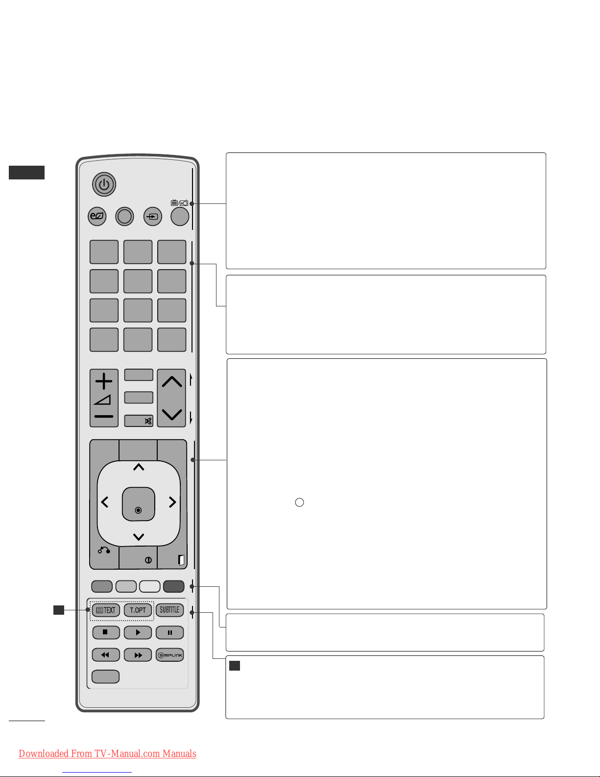
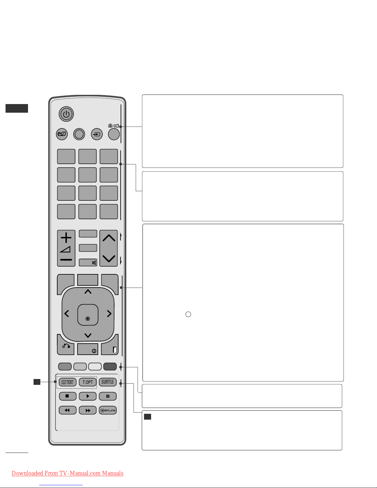
REMOTE CONTROL KEY FUNCTIONS
(Except for 42/50PJ2**, 50/60PK2**)
When using the remote control, aim it at the remote control sensor on the TV.
P
A
G
E
P
123
4506
789
LIST
Q.VIEW
AV MODE INPUT
TV/
RAD
ENERGY
SAVING
MARK
FAV
RATIO
MUTE
MENU
GUIDE
Q.MENU
BACK
INFO
EXIT
OK
FREEZE
AD
rr
(POWER)
ENERGY SAVING
AV MODE
INPUT
TV/RAD
Switches the TV on from standby or off to standby.
Adjust the Energy Saving mode of the TV.(
GG
pp..77 44
)
It helps you select and set images and sounds when connecting AV devices.(
GG
pp..33 88
)
External input mode rotate in regular sequence.
(
GG
pp..33 22
)
Selects Radio, TV and DTV channel.
0 to 9 number
button
LIST
Q.VIEW
Selects a programme.
Selects numbered items in a menu.
Displays the programme table.
(
GG
pp..33 00
)
Returns to the previously viewed programme.
Coloured
buttons
These buttons are used for teletext (on
TTEE LL EETT EE XXTT
models only) ,
PPrrooggrraamm mm ee eeddii tt
.
TELETEXT
BUTTONS
SUBTITLE
These buttons are used for teletext.
For further details, see the ‘Teletext’ section.(
GG
pp..1100 77
)
Recalls your preferred subtitle in digital mode.
1
1
A-10
PREPARATION
PREPARATION
MENU
GUIDE
Q. MENU
BACK
INFO i
EXIT
THUMBSTICK
(Up/Down/Left/Right)
OK
Selects a menu.
Clears all on-screen displays and returns to TV viewing
from any menu.
(
GG
pp..11 66
)
Shows programme schedule.
(
GG
pp..66 88
)
Select the desired quick menu source. (Aspect Ratio,
Clear Voice II , Picture Mode, Sound Mode, Audio, Sleep
Timer, Favourite, USB Device).
(
GG
pp..11 55
)
Allows the user to move return one step in an interactive
application, EPG or other user interaction function.
Shows the present screen information.
Clears all on-screen displays and returns to TV viewing
from any menu.
Allows you to navigate the on-screen menus and adjust
the system settings to your preference.
Accepts your selection or displays the current mode.
Downloaded From TV-Manual.com Manuals
A-11
PREPARATION
P
A
G
E
P
123
4506
789
LIST
Q.VIEW
AV MODE INPUT
TV/
RAD
ENERGY
SAVING
MARK
FAV
RATIO
MUTE
MENU
GUIDE
Q.MENU
BACK
INFO
EXIT
OK
FREEZE
AD
VOLUME UP
/DOWN
FAV
MARK
RATIO
MUTE
Programme
UP/DOWN
PAGE
UP/DOWN
Adjusts the volume.
Displays the selected favourite programme.
Select the input to apply the Picture Wizard settings.
Check and un-check programmes in the USB menu.
Selects your desired Aspect Ratio of picture.(
GG
pp..77 11
)
Switches the sound on or off.
Selects a programme.
Move from one full set of screen information to the next
one.
AD
See a list of AV devices connected to TV.
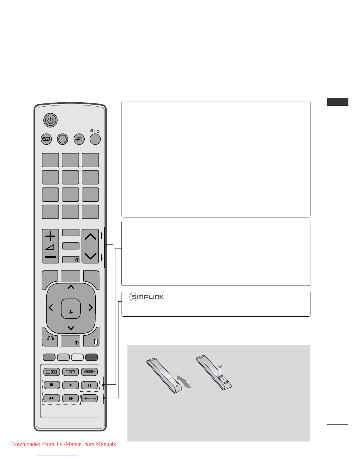
When you toggle this button, the Simplink menu
appears at the screen.(
GG
pp..33 55
)
Switches the Audio Description On or Off.
Installing Batteries
■
Open the battery compartment cover on the back and install the
batteries matching correct polarity (+with +,-with -).
■
Install two 1.5 V AAA batteries. Do not mix old or used batteries
with new ones.
■
Close cover.
■
To remove the batteries, perform the installation actions in reverse.
SIMPLINK /
USB Menu
control buttons
FREEZE
Controls SIMPLINK or USB menu(Photo List and Music
List or Movie List
(Only 42/50PJ5**, 42/50PJ6**, 50PK3**,
50/60PK5**, 50PK7
**
)
Pause the present picture at the screen. (It doesn't
work at USB Mode and Simplink.)
The TV returns to normal viewing automatically if no
signal is received or no operation is performed for 5
minutes.
Downloaded From TV-Manual.com Manuals
A-12
PREPARATION
PREPARATION
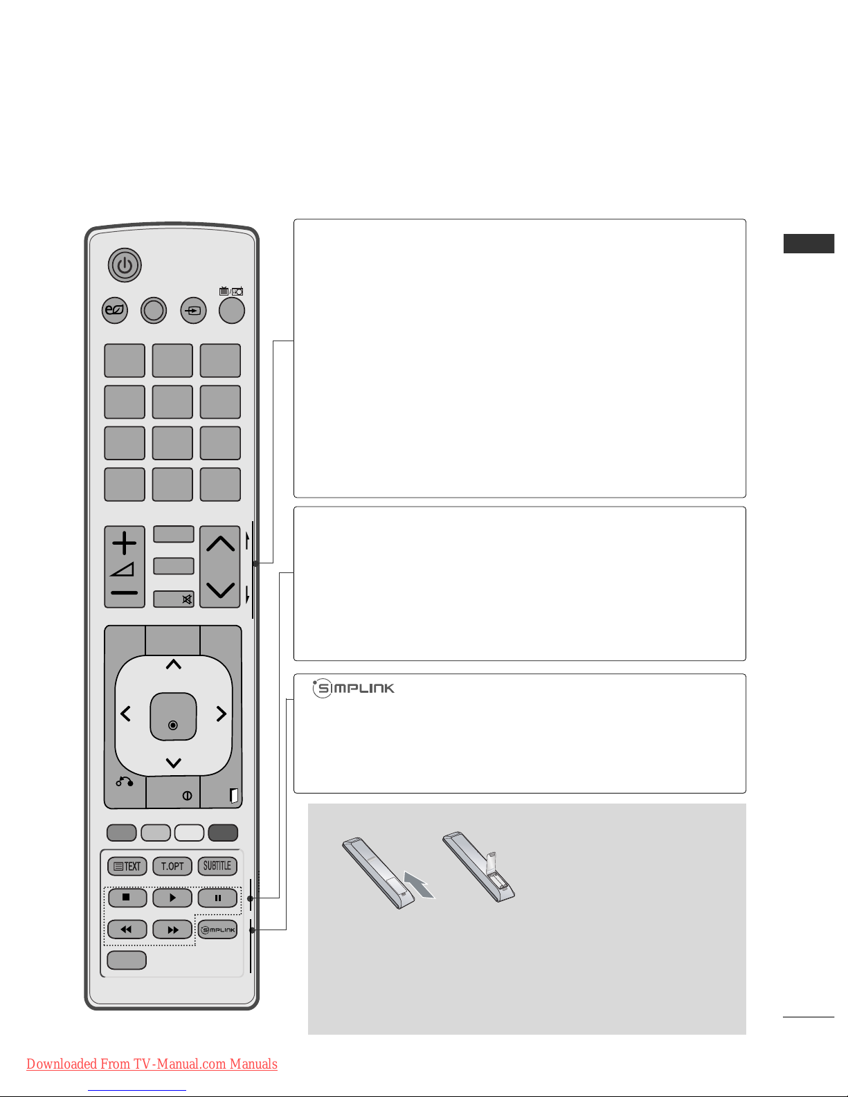
REMOTE CONTROL KEY FUNCTIONS
(Only 42/50PJ2**, 50/60PK2**)
When using the remote control, aim it at the remote control sensor on the TV.
P
A
G
E
P
123
4506
789
LIST
Q.VIEW
AV MODE INPUT
TV/
RAD
ENERGY
SAVING
MARK
FAV
RATIO
MUTE
MENU
GUIDE
Q.MENU
BACK
INFO
EXIT
OK
FREEZE
rr
(POWER)
ENERGY SAVING
AV MODE
INPUT
TV/RAD
Switches the TV on from standby or off to standby.
Adjust the Energy Saving mode of the TV.(
GG
pp..77 44
)
It helps you select and set images and sounds when connecting AV devices.(
GG
pp..33 88
)
External input mode rotate in regular sequence.
(
GG
pp..33 22
)
Selects Radio, TV and DTV channel.
0 to 9 number
button
LIST
Q.VIEW
Selects a programme.
Selects numbered items in a menu.
Displays the programme table.
(
GG
pp..33 00
)
Returns to the previously viewed programme.
Coloured
buttons
These buttons are used for teletext (on
TTEE LL EETT EE XXTT
models only) ,
PPrrooggrraamm mm ee eeddii tt
.
TELETEXT
BUTTONS
SUBTITLE
These buttons are used for teletext.
For further details, see the ‘Teletext’ section.(
GG
pp..1100 77
)
Recalls your preferred subtitle in digital mode.
1
1
MENU
GUIDE
Q. MENU
BACK
INFO i
EXIT
THUMBSTICK
(Up/Down/Left/Right)
OK
Selects a menu.
Clears all on-screen displays and returns to TV viewing
from any menu.
(
GG
pp..11 66
)
Shows programme schedule.
(
GG
pp..66 88
)
Select the desired quick menu source. (Aspect Ratio,
Clear Voice II , Picture Mode, Sound Mode, Audio, Sleep
Timer, Favourite, Energy Saving).
(
GG
pp..11 55
)
Allows the user to move return one step in an interactive
application, EPG or other user interaction function.
Shows the present screen information.
Clears all on-screen displays and returns to TV viewing
from any menu.
Allows you to navigate the on-screen menus and adjust
the system settings to your preference.
Accepts your selection or displays the current mode.
Downloaded From TV-Manual.com Manuals
P
A
G
E
P
123
4506
789
LIST
Q.VIEW
AV MODE INPUT
TV/
RAD
ENERGY
SAVING
MARK
FAV
RATIO
MUTE
MENU
GUIDE
Q.MENU
BACK
INFO
EXIT
OK
FREEZE
A-13
PREPARATION
VOLUME UP
/DOWN
FAV
MARK
RATIO
MUTE
Programme
UP/DOWN
PAGE
UP/DOWN
Adjusts the volume.
Displays the selected favourite programme.
Select the input to apply the Picture Wizard settings.
Check and un-check programmes in the USB menu.
Selects your desired Aspect Ratio of picture.(
GG
pp..77 11
)
Switches the sound on or off.
Selects a programme.
Move from one full set of screen information to the next
one.
See a list of AV devices connected to TV.
When you toggle this button, the Simplink menu
appears at the screen.(
GG
pp..33 55
)
Installing Batteries
■
Open the battery compartment cover on the back and install the
batteries matching correct polarity (+with +,-with -).
■
Install two 1.5 V AAA batteries. Do not mix old or used batteries
with new ones.
■
Close cover.
■
To remove the batteries, perform the installation actions in reverse.
SIMPLINK con-
trol buttons
FREEZE
Controls SIMPLINK.
Pause the present picture at the screen. (It doesn't
work at USB Mode and Simplink.)
The TV returns to normal viewing automatically if no
signal is received or no operation is performed for 5
minutes.
Downloaded From TV-Manual.com Manuals

Downloaded From TV-Manual.com Manuals
1
EXTERNAL EQUIPMENT SETUP
EXTERNAL EQUIPMENT SETUP
■
To prevent damage do not connect to the mains outlet until all connections are made between the devices.
AV IN 3
L/ MONO
R
AUDIO
VIDEO
S-VIDEO
USB IN
SERVICE ONLY
COMPONENT IN
IN 2
AV IN 3
L/ MONO
R
AUDIO
VIDEO
S-VIDEO
USB IN
SERVICE ONLY
COMPONENT IN
IN 2
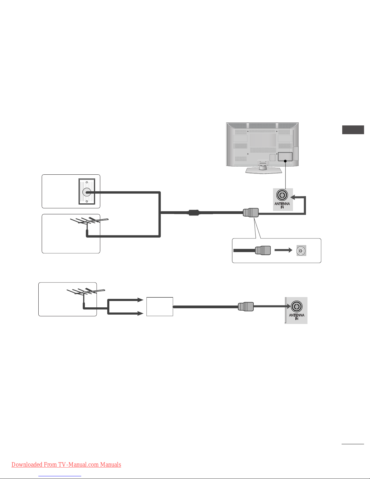
ANTENNA CONNECTION
■
For optimum picture quality, adjust antenna direction.
■
An antenna cable and converter are not supplied.
Multi-family Dwellings/Apartments
(Connect to wall antenna socket)
Single-family Dwellings /Houses
(Connect to wall jack for outdoor antenna)
Outdoor
Antenna
(VHF, UHF)
Wall
Antenna
Socket
RF Coaxial Wire (75 Ω)
Antenna
UHF
Signal
Amplifier
VHF
■
In poor signal areas, to achieve better picture quality it may be necessary to install a signal amplifier to the
antenna as shown above.
■
If signal needs to be split for two TVs,use an antenna signal splitter for connection.
L/MONO
R
AUDIO
VIDEO
S-VIDEO
USB IN
SERVICE ONLY
IN 2
Downloaded From TV-Manual.com Manuals
2
EXTERNAL EQUIPMENT SETUP
EXTERNAL EQUIPMENT SETUP
■
To avoid damaging any equipment, never plug in any power cord until you have finished connecting all equipment.
■
This section on EXTERNAL EQUIPMENT SETUP mainly uses diagrams for the 50/60PK5**models.
■
Image shown may differ from your TV.
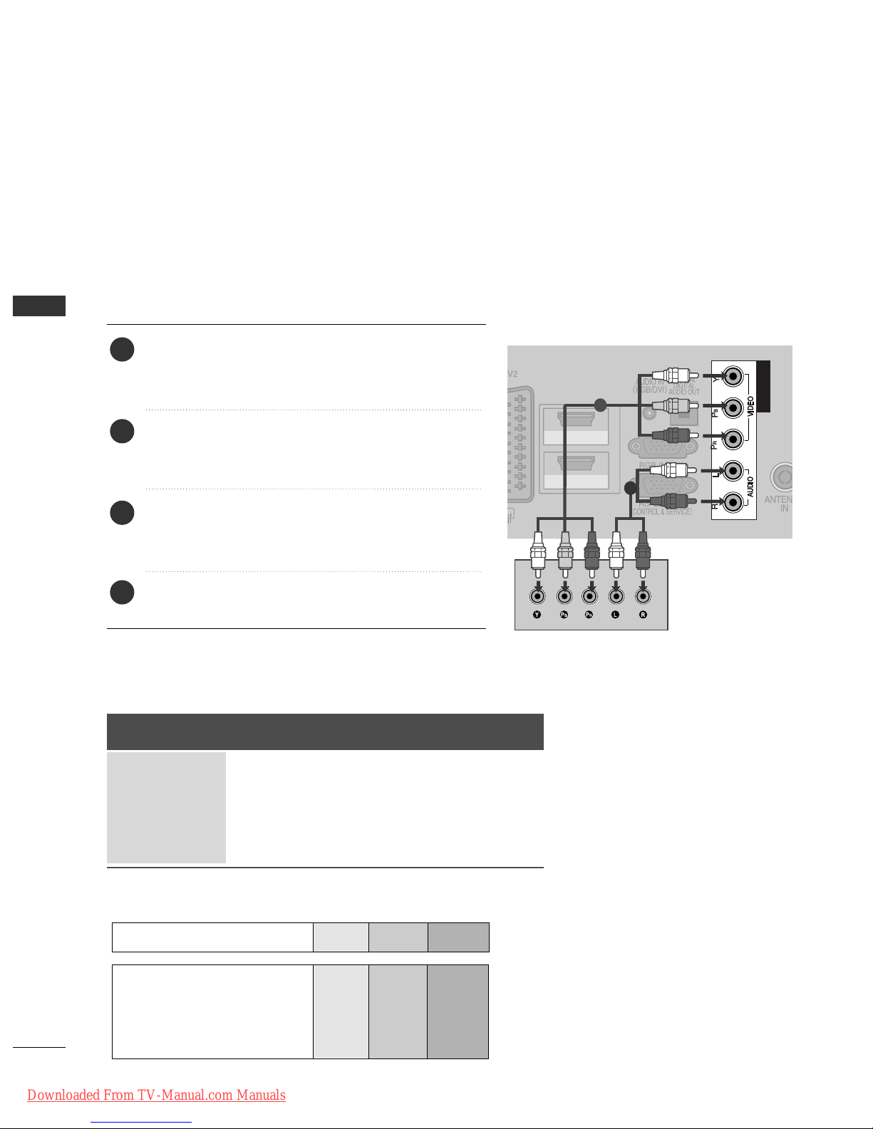
CONNECTING WITH A COMPONENT CABLE
HDMI/DVI IN
HDMI IN
1
2
COMPONENT INCOMPONENT IN
COMPONENT IN
1
2
Signal
480i/576i
480p/576p
720p/1080i
1080p
Component
O
O
O
O
(50 Hz / 60 Hz only)
HDMI
X
O
O
O
(24 Hz/30 Hz/50 Hz/60 Hz)
■
This TV can receive Digital RF/Cable signals without an external digital set-top box. However, if you do receive
Digital signals from a digital set-top box or other digital external device, refer to the diagram as shown below.
Connect the video outputs (Y, PB, PR
)
of the external
equipment (digital set-top box, DVD, etc.) to the
CCOO MM--
PPOONN EE NN TT IINN VVIIDDEEOO
jacks on the TV.
Connect the audio output of the external equipment
(digital set-top box, DVD, etc.) to the
CCOO MMPPOO NNEENNTT
II NN AA UUDDIIOO
jacks on the TV.
Turn on the external equipment.
(
Refer to the external equipment's manual for operating
instructions.)
Select the
CCoomm ppoonneenntt
input source using the
II NN PPUUTT
button on the remote control.
2
3
4
1
GG
HDMI Audio Supported format : Dolby Digital, PCM
DTS Audio format is not supported.
Component Input ports
To achieve better picture quality, connect a DVD player to the component input ports as shown below.
Component ports on the TV
YPB PR
Video output ports
on DVD player
Y
Y
Y
Y
P
B
B-Y
Cb
Pb
PR
R-Y
Cr
Pr
Downloaded From TV-Manual.com Manuals
3
EXTERNAL EQUIPMENT SETUP
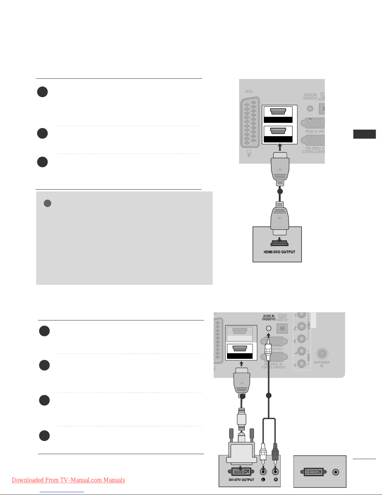
CONNECTING WITH AN HDMI CABLE
COMPONENT IN
HDMI/DVI IN
1
2
HDMI IN
COMPONENT IN
1
Connect the HDMI output of the external equipment
(digital set-top box, DVD, etc.) to
HH DDMMII//DDVVII IINN11
(or
HH DDMMII//DDVVII IINN),HH DDMMII IINN 22
(Except for
42/50PJ2**)
or
HH DDMMII IINN 33
(Only 50/60PK5**,
50PK7**)
jack on the TV.
Turn on the external equipment.
(
Refer to the external equipment's manual for operat-
ing instructions.)
Select
HH DDMMII 11
(or
HH DDMMII
)
,
HH DDMMII 22
(Except for
42/50PJ2**)
or
HH DDMMII 33
(Only 50/60PK5**, 50PK7**)
input source using the
II NN PPUUTT
button on the remote
control.
2
3
1
2
GG
The TV can receive video and audio signals simultaneously
when using an HDMI cable.
GG
If the DVD does not support Auto HDMI, you must set the
output resolution appropriately.
GG
Check that your HDMI cable is version 1.3 or higher.
If the HDMI cables don’t support HDMI version 1.3, flickering or no screen display can result. Please use the latest
cables that support at least HDMI version 1.3.
NOTE
!
COMPONENTCOMPONENT IN
HDMI/DVI IN
1
HDMI IN
2
DVI-PC OUTPUT
AUDIO
CONNECTING WITH AN HDMI TO DVI CABLE
1
2
Connect the digital set-top box or the DVI output of
the PC to
HH DDMMII//DDVVII IINN 11
(or
HH DDMMII//DDVVII IINN
)
jack
on the TV.
Connect the audio output of the digital set-top box or
the PC audio output to the
AA UUDD IIOO IINN ((RRGGBB//DD VVII))
(
or
AA UUDD IIOO IINN ((DD VVII))
)
jack on the TV.
Turn on the digital set-top box or the PC and the TV.
(
Refer to the digital set-top box or the PC manual for
operating instructions.)
Select
HHDDMM II11
(or
HH DDMMII
) input source using the
II NN PPUUTT
button on the remote control.
2
3
4
1
or
Downloaded From TV-Manual.com Manuals
4
EXTERNAL EQUIPMENT SETUP
EXTERNAL EQUIPMENT SETUP
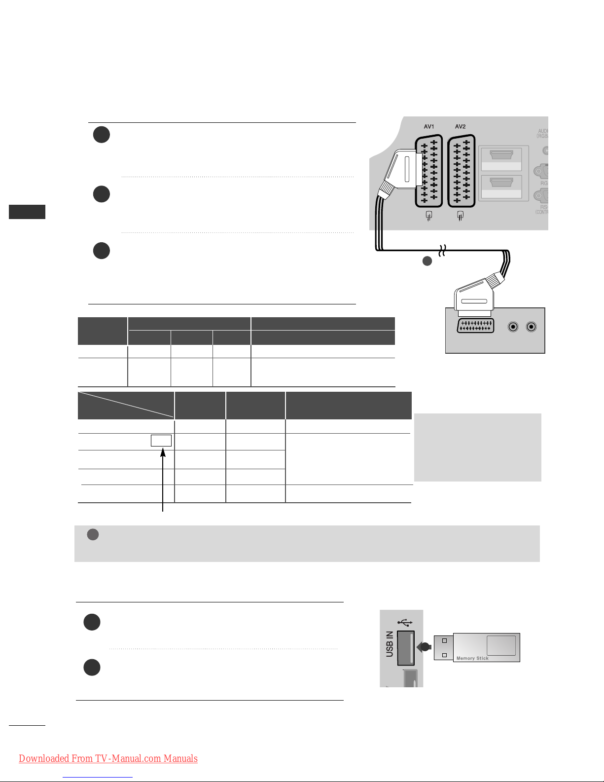
CONNECTING WITH A EURO SCART CABLE
HDMI/DVI IN
HDMI IN
1
2
(R) AUDIO (L)
AUDIO/
VIDEO
COMPONENT IN
1
2
3
1
Connect the Euro scart socket of the external equipment (DVD, VCR, etc.) to the
AA VV 11
Euro scart socket on
the TV.
Turn on the external equipment.
(
Refer to the external equipment's manual for operating
instructions.)
Select
AAVV11
input source using the
II NN PPUUTT
button on
the remote control.
If connected to
AAVV22
Euro scart socket, select
AAVV22
input source.
Scart
AV1
AV2
Input
Video Audio RGB
Output
Video, Audio
Analogue only
Analogue
, DTV, AV1, AV2, AV3(Except for
42/50PJ2**, 50/60PK2**) output is available.
OOO
OOX
GG
TV Out : Outputs analogue
TV signals.
Monitor Out: Outputs
the current screen image.
Digital TV
Analogue TV, AV1,AV3
Component/RGB
HDMI
AV2
AV1
(TV Out)
XO O
OO O
OX
XX
OO O
AV2
(Monitor Out)
AV2
(When DTV scheduled recording is in
progress using recording equipment.)
(The input mode is converted to
DTV.)
Output Type
Current
input mode
(Except for 42/50PJ2**, 50/60PK2**)
NOTE
!
GG
Any Euro scart cable used must be signal shielded.
USB SETUP
(Except for 42/50PJ2**, 50/60PK2**)
1
Connect the USB device to the
UU SS BB IINN
jack on the
TV.
After connecting the
UU SS BB IINN
jack, you use the
UU SS BB
function. (
GG
pp ..4488
)
2
1
Downloaded From TV-Manual.com Manuals
5
EXTERNAL EQUIPMENT SETUP
AV IN 3
L/ MONO
R
AUDIO
VIDEO
S-VIDEO HDMI IN 3
HDMI IN 3
AV IN 3
L/MONO
R
AUDIOAUDIO
VIDEOVIDEO
L
R
S-VIDEO
VIDEO
OUTPUT
SWITCH
ANT IN
ANT OUT
L R
VIDEO
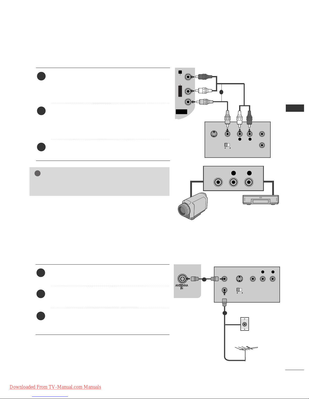
CONNECTING WITH A RCA CABLE
(Except for 42/50PJ2**, 50/60PK2**)
Connect the
AA UU DDII OO/VVIIDDEE OO
jacks between TV and
VCR or external equipment. Match the jack colours
(Video = yellow, Audio Left = white, and Audio Right =
red)
Insert a video tape into the VCR and press PLAY on
the VCR. (Refer to the VCR owner’s manual.
)
Or, Operate the corresponding external equipment.
(Refer to external equipment operating guide.)
Select
AAVV33
input source using the
II NN PPUUTT
button on
the remote control.
1
2
3
GG
If you have a mono VCR, connect the audio cable from the
VCR to the
AA UUDD IIOO LL //MMOONNOO
jack of the TV.
NOTE
!
1
Camcorder
Video Game Set
or
R
S-VIDEO HDMI IN 3
COMPONENT IN
OUTPUT
SWITCH
ANT IN
R
S-VIDEO VIDEO
ANT OUT
L
CONNECTING WITH A RF CABLE
■
To avoid picture noise (interference), allow adequate distance between the VCR and TV.
Connect the
AA NNTT OOUUTT
socket of the VCR to the
AA NNTT EENNNNAA IINN
socket on the TV.
Connect the antenna cable to the
AA NNTT II NN
socket of
the VCR.
Press the
PPLLAAYY
button on the VCR and match the
appropriate channel between the TV and VCR for
viewing.
1
2
3
Wall Jack
Antenna
1
2
Downloaded From TV-Manual.com Manuals
6
EXTERNAL EQUIPMENT SETUP
EXTERNAL EQUIPMENT SETUP
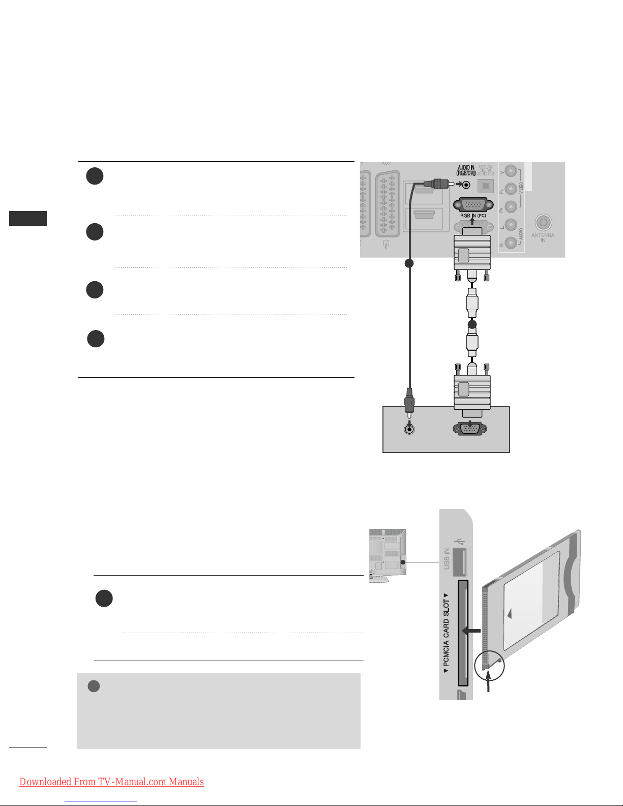
CONNECTING WITH A D-SUB 15 PIN CABLE
(Except for
42/50PJ2**, 50/60PK2**)
This TV provides Plug and Play capability, meaning that the PC adjusts automatically to the TV's settings.
HDMI/DVI IN
HDMI IN
1
2
AUDIO
RGB OUTPUT
COMPONENT IN
1
2
4
Connect the RGB output of the PC to the
RRGGBB II NN
(( PP CC))
jack on the TV.
Connect the PC audio output to the
AA UUDD IIOO IINN
(( RRGGBB// DDVV II))
jack on the TV.
Turn on the PC and the TV
Select
RRGG BB
input source using the INPUT button on
the remote control.
2
3
1
GG
Check if the CI module is inserted into the PCMCIA card slot in
the right direction. If the module is not inserted properly, this
can cause damage to the TV and the PCMCIA card slot.
NOTE
!
Insert the CI Module to
PPCC MM CC II AA
(Personal Computer
Memory Card International Association)
CC AARRDD SSLL OOTT
of TV as shown.
For further information, see p.29.
1
INSERTION OF CI MODULE
-- TToo vviieeww tt hh ee eenncc rryypptt eedd (( ppaa yy)) ssee rrvvii ccee ss iinn ddiiggiitt aall TTVV
mmooddee..
-- TThhii ss ff eeaa ttuurr ee iiss nnoo tt aavvaaii llaa bbllee iinn aallll cc oouunnttrriieess..
AV IN 3
L/MONO
R
AUDIO
VIDEO
S-VIDEO
USB IN
SERVICE ONLY
IN 2
Check this point as shown
and insert the CI Module.
Downloaded From TV-Manual.com Manuals
7
EXTERNAL EQUIPMENT SETUP
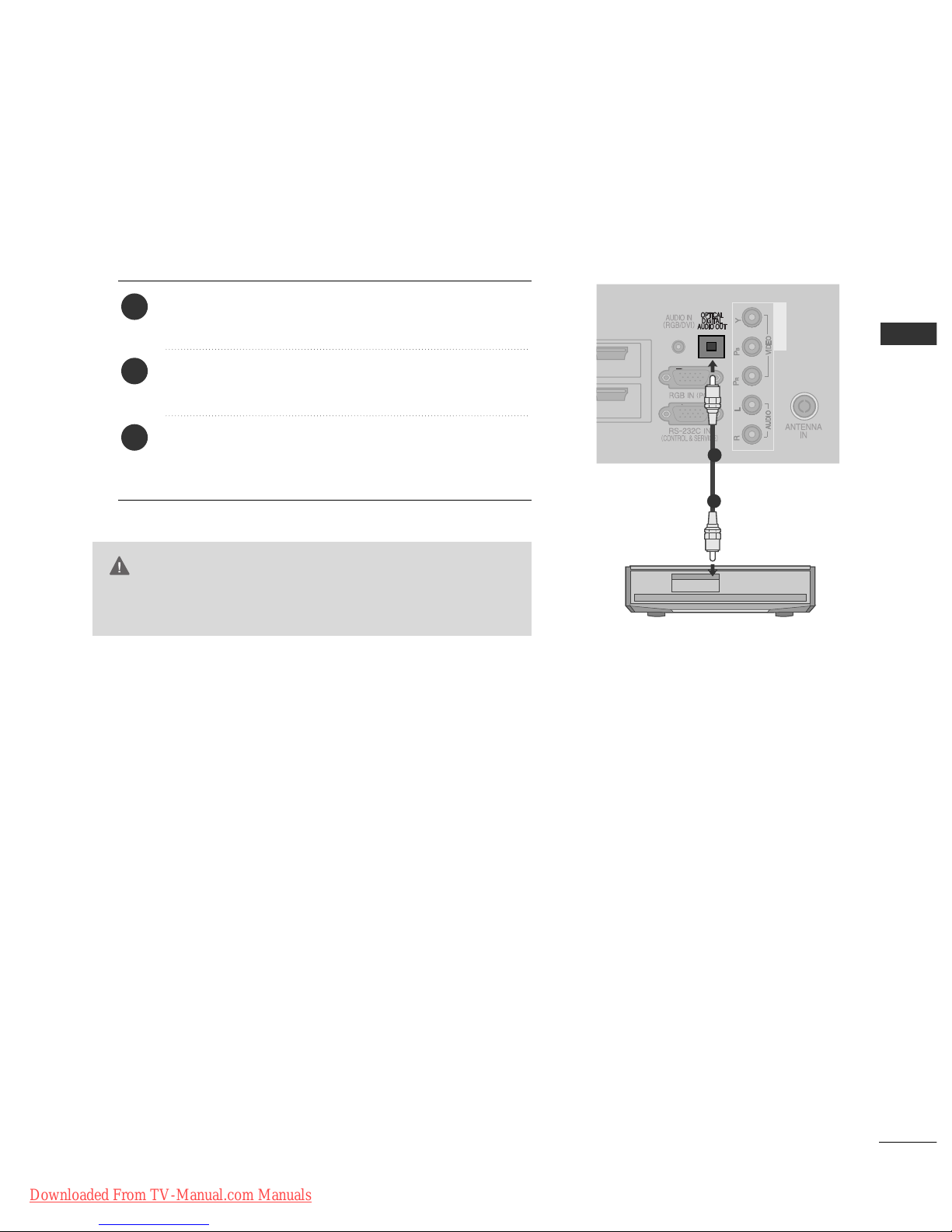
G
Do not look into the optical output port. Looking at the
laser beam may damage your vision.
CAUTION
HDMI IN
1
2
COMPONENT IN
Connect one end of an optical cable to the TV Digital
Audio (Optical)Output port.
Connect the other end of the optical cable to the digital audio (Optical)input on the audio equipment.
Set the “TV Speaker option - Off ” in the AUDIO
menu.(
G
pp ..9900
). Refer to the external audio equipment
instruction manual for operation.
2
3
1
1
2
DIGITAL AUDIO OUT SETUP
Sending the TV’s audio signal to external audio equipment via the Digital Audio Output (Optical) port.
If you want to enjoy digital broadcasting through 5.1-channel speakers, connect the OPTICAL DIGITAL
AUDIO OUT terminal on the back of TV to a Home Theater (or amp).
Downloaded From TV-Manual.com Manuals
8
EXTERNAL EQUIPMENT SETUP
EXTERNAL EQUIPMENT SETUP
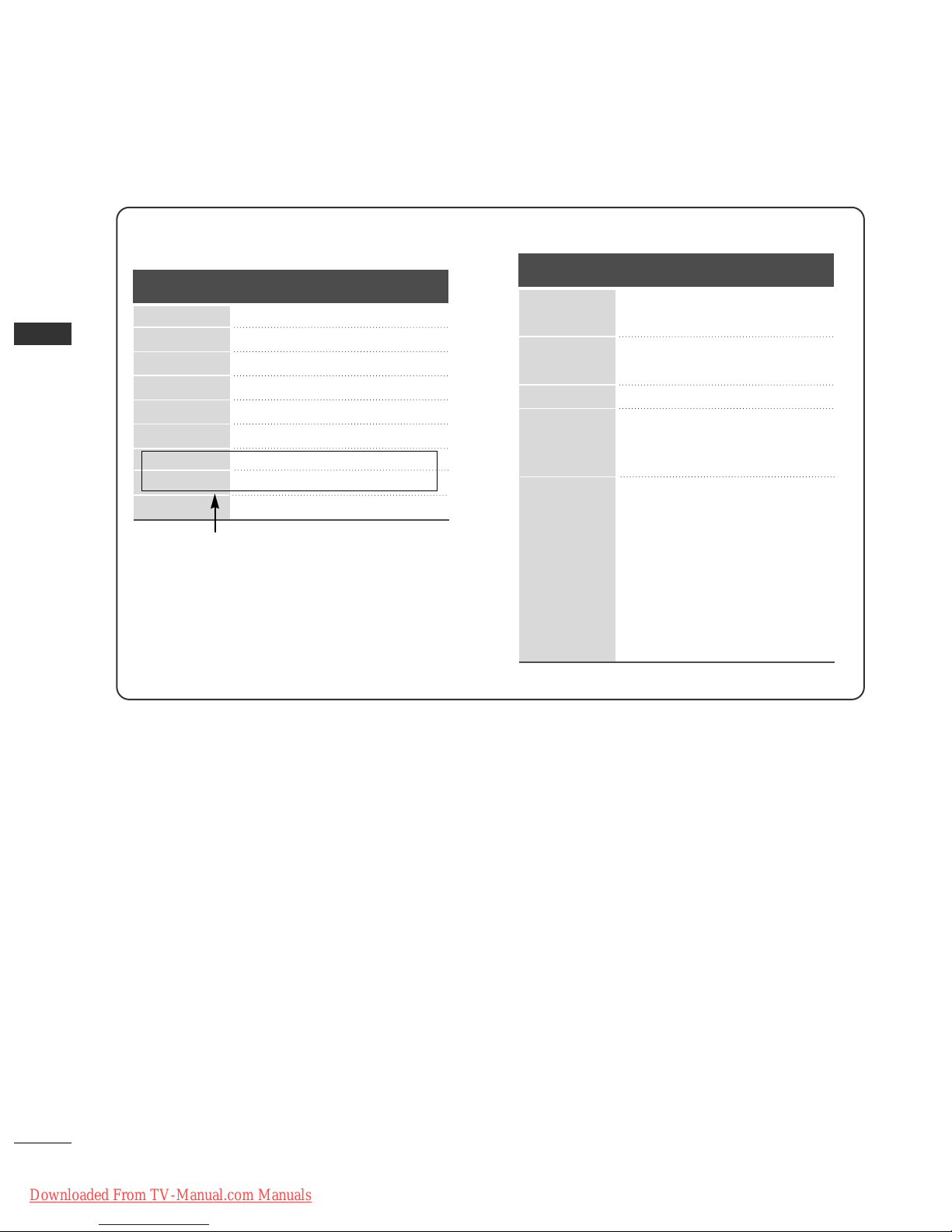
Supported Display Resolution
70.08
59.94
60.31
60.00
59.87
59.8
60.02
59.979
59.934
31.468
31.469
37.879
48.363
47.78
47.72
63.98
65.317
66.587
Resolution
Horizontal
Frequency(kHz)
Vertical
Frequency(Hz)
RGB-PC, HDMI/DVI-PC mode (Except for
42/50PJ2**, 50/60PK2**)
HDMI/DVI-DTV mode
59.94
60
59.94
60
50.00
50.00
59.94
60
50.00
59.94
60
24.00
30
50.00
59.94
60
31.649
31.469
31.47
31.50
31.25
37.50
44.96
45.00
28.125
33.72
33.75
27.00
33.75
56.25
67.433
67.50
Resolution
Horizontal
Frequency(kHz)
Vertical
Frequency(Hz)
640x480
720x480
720x576
1280x720
1920x1080
720x400
640x480
800x600
1024x768
1280x768
1360x768
1280x1024
1400x1050
1920x1080
(Only 50PK3**, 50/60PK5**,
50PK7**, )
Downloaded From TV-Manual.com Manuals

9
EXTERNAL EQUIPMENT SETUP
NOTE
!
G
Avoid keeping a fixed image on the set’s screen
for prolonged periods of time. The fixed image
may become permanently imprinted on the
screen; use a screen saver when possible.
G
There may be interference relating to resolution,
vertical pattern, contrast or brightness in PC
mode. Change the PC mode to another resolution or change the refresh rate to another rate or
adjust the brightness and contrast on the menu
until the picture is clear. If the refresh rate of the
PC graphic card can not be changed, change the
PC graphic card or consult the manufacturer of
the PC graphic card.
G
The synchronization input waveform for
Horizontal and Vertical frequencies are separate.
G
We recommend using 1024 x 768, 60 Hz(Only
42PJ3**, 42PJ5**, 42PJ6**), 1360 x 768, 60
Hz(Only 50PJ3**, 50PJ5**, 50PJ6**), 1920 x 1080,
60 Hz(Only 50PK3**, 50/60PK5**, 50PK7**) for
the PC mode, they provide the best picture quality.
G
Connect the signal cable from the monitor output port of the PC to the RGB (PC) port of the
TV or the signal cable from the HDMI output
port of the PC to the HDMI IN (or HDMI/DVI
IN) port on the TV.
G
Connect the audio cable from the PC to the
Audio input on the TV. (Audio cables are not
included with the TV).
G
If using a sound card, adjust PC sound as
required.
G
If the graphic card on the PC does not output
analogue and digital RGB simultaneously, connect
only one of either RGB or HDMI IN (or
HDMI/DVI IN) to display the PC output on the
TV.
G
If the graphic card on the PC does output analog
and digital RGB simultaneously, set the TV to
either RGB or HDMI; (the other mode is set to
Plug and Play automatically by the TV.)
G
DOS mode may not work depending on the video
card if you use an HDMI to DVI cable.
G
If you use an RGB-PC cable that is too long,
there may be interference on the screen. We recommend using under 5 m of cable. This provides
the best picture quality.
Downloaded From TV-Manual.com Manuals
OK
Move
• Brightness 50
• Sharpness 70
• Colour 70
• Tint 0
•
Colour Temperature
0
• Advanced Control
• Picture Reset
Screen
PICTURE
RG
E
WC
Screen
10
EXTERNAL EQUIPMENT SETUP
EXTERNAL EQUIPMENT SETUP
1
MENU
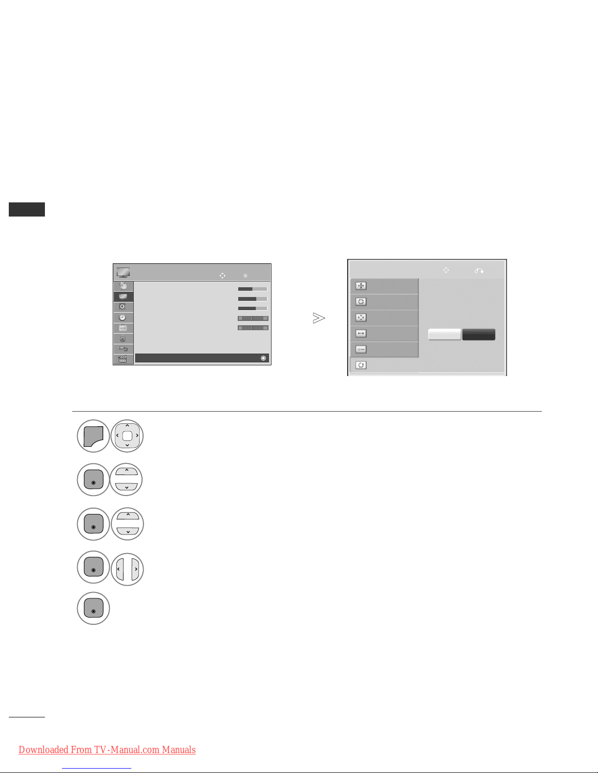
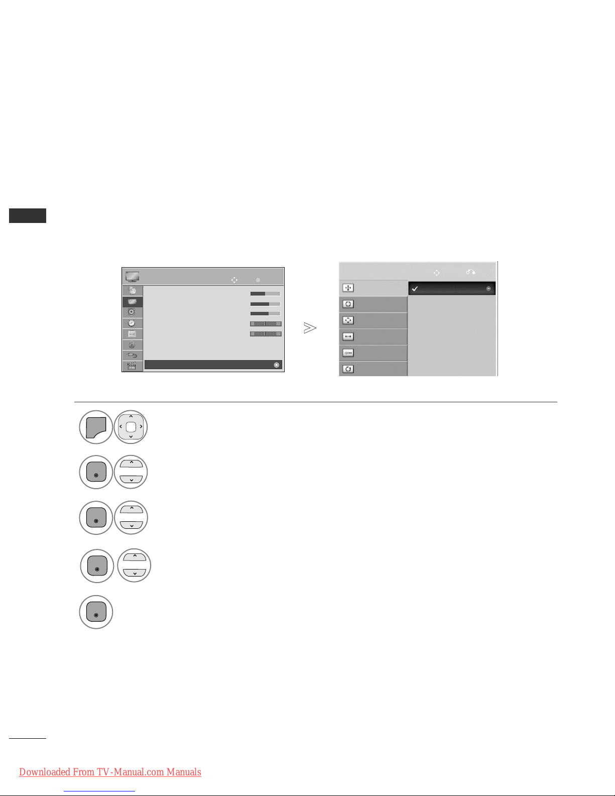
Screen Setup for PC mode(Except for 42/50PJ2**, 50/60PK2**)
Returns Position, Size and Phase to the factory default settings.
This function works in the following mode : RGB[PC].
Screen Reset
Select
PPII CC TTUU RREE
.
Select
SSccrree eenn
.
3
Select
RReess eett
.
2
OK
OK
• Press the
MMEENNUU//EEXXIITT
button to return to normal TV viewing.
• Press the
BBAACCKK
button to move to the previous menu screen.
Select
YYee ss
.
Run
RReess eett
.
4
OK
5
OK
To Set
Auto Config.
SCREEN
Move
Prev.
Resolution
Position
Size
Phase
Reset
Yes No
Downloaded From TV-Manual.com Manuals
OK
Move
• Brightness 50
• Sharpness 70
• Colour 70
• Tint 0
•
Colour Temperature
0
• Advanced Control
• Picture Reset
Screen
PICTURE
RG
E
WC
Screen
11
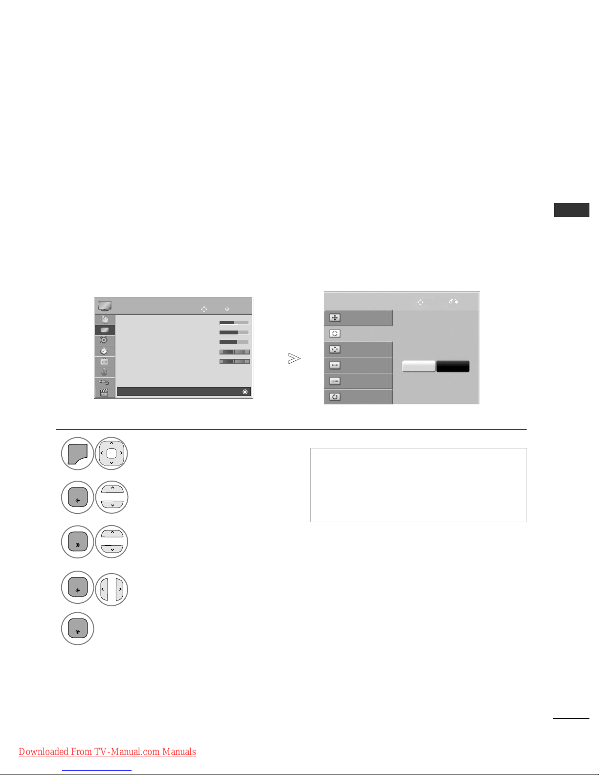
EXTERNAL EQUIPMENT SETUP
Automatically adjusts the picture position and minimizes image instability. After adjustment, if the image is
still not correct, your TV is functioning properly but needs further adjustment.
AAuuttoo ccoo nn ffiigguurr ee
This function is for automatic adjustment of the screen position, size, and phase The displayed image will be
unstable for a few seconds while the auto configuration is in progress.
Auto Configure (RGB [PC] mode only)
• If the position of the image is still not correct,
try Auto adjustment again.
• If picture needs to be adjusted again after Auto
adjustment in RGB (PC), you can adjust the
PPoossiitt iioonn, SSiizz ee
or
PPhhaassee
.
Select
PPII CC TTUU RREE
.
Select
SSccrree eenn
.
Select
AA uutt oo CC oonnffiigg..
.
1
MENU
3
2
OK
OK
•
Press the
MMEENNUU//EEXXIITT
button to return to normal TV viewing.
• Press the
BBAA CCKK
button to move to the previous menu screen.
Select
YYee ss
.
Run
AA uutt oo CC oonnffiigg..
.
4
OK
5
OK
To Set
Auto Config.
SCREEN
Move
Prev.
Resolution
Position
Size
Phase
Reset
Yes No
Downloaded From TV-Manual.com Manuals
OK
Move
• Brightness 50
• Sharpness 70
• Colour 70
• Tint 0
•
Colour Temperature
0
• Advanced Control
• Picture Reset
Screen
PICTURE
RG
E
WC
Screen
12
EXTERNAL EQUIPMENT SETUP
EXTERNAL EQUIPMENT SETUP
To view a normal picture, match the resolution of RGB mode and selection of PC mode.
This function works in the following mode: RGB[PC]
Selecting Resolution
Select
PPII CC TTUU RREE
.
Select
SSccrree eenn
.
Select
RReessooll uutt iioonn
.
Select the desired resolution.
1
MENU
3
4
2
OK
OK
OK
5
OK
• Press the
MMEENNUU//EEXXIITT
button to return to normal TV viewing.
• Press the
BBAA CCKK
button to move to the previous menu screen.
Auto Config.
SCREEN
Move
Prev.
Resolution
Position
Size
Phase
Reset
1024 x 768
1280 x 768
1360 x 768
Downloaded From TV-Manual.com Manuals
 Loading...