

Page 1

IIDD NNuummbbeerr::
5513: 50PG79ED
OWNER’S MANUAL
PP LLAA SS MM AA TT VV MM OO DDEE LL SS
5500PP GG77
******
PLASMA TV
PP ll eeaassee rr eeaadd tthhiiss mmaann uuaall ccaarreeff uullll yy bbeeffoorree
ooppee rr aattiinngg yyoouurr TTVV..
RReettaaiinn iitt ffoorr ff uuttuu rr ee rreeffee rr eennccee..
RReecc oorrdd mmoo ddeell nnuu mmbbeerr aanndd ss eerriiaall nnuu mmbbeerr ooff
tthhee TTVV..
RReeffeerr tt oo tthh ee llaabbee ll oonn tthhee bbaa cckk cc oovv eerr aanndd
qquuoottee tthhiiss iinn ffoorrmmaattiioonn..
TToo yyoouu rr ddeeaallee rr wwhheenn rreeqquuiirriinngg ssee rrvviiccee..
DVB is a registered trademark
of the DVB Project
Page 2

Manufactured under license from Dolby
Laboratories. ‘Dolby’ and the ‘double-D’
symbol are trademarks of Dolby
Laboratories.
Page 3

Protection Cover Ferrite Core
i
OK
TVD/A
INPUT
DVD
SIMPLINK
EXIT
VOL
SIZE
INDEX
TIME
REVEAL
Q.VIEW
PR
MARK
LIVE
I/II
TEXT
GUIDE
VCR
POWER
123
456
789
0
LIST
?
MODE
BRIGHT
MENU
MUTE
INPUT
FAV
SLEEP
PAGE
USB
INFO
i
PIP PR- PIP PR+
PIP INPUTSWAP
TIME
SHIFT
TIME
SHIFT
SUBTITLE
RATIO
PIP
1
ACCESSORIES
ACCESSORIES
Ensure that the following accessories are included with your TV. If an accessory is missing, please contact the
dealer where you purchased the product.
Owner’s Manual Batteries Remote Control Power Cord
Polishing Cloth
Polishing cloth for use on
the screen.
This feature is not available for all models.
* Lightly wipe any stains or fingerprints on the
surface of the TV with the polishing cloth.
Do not use excessive force. This may cause
scratching or discolouration.
Cable management clip
A
Image shown may differ from your TV.
Ferrite core can be used to reduce the electromagnetic
wave when connecting the power cord.
The closer the location of the ferrite core to the power
plug, the better it is.
Use of Ferrite Core
Install as close as possible to
the power plug.
Page 4

CONTENTS
2
CONTENTS
ACCESSORIES
. . . . . . . . . . . . . . . . . . . . . . . . . . . . . . . . . . . . . . . . . . .
1
PREPARATION
Home Menu . . . . . . . . . . . . . . . . . . . . . . . . . . . . . 4
Front Panel Controls . . . . . . . . . . . . . . . . . . . . . . 5
Back Panel Information . . . . . . . . . . . . . . . . . . . . 6
Back Cover for Wire Arrangement . . . . . . . . . . . . 7
Desktop Pedestal Installation . . . . . . . . . . . . . . . . 8
Swivel Stand . . . . . . . . . . . . . . . . . . . . . . . . . . . . . 8
Wall Mount: Horizontal Installation . . . . . . . . . . . .9
Not Using the Desk-type Stand . . . . . . . . . . . . . . . . .9
Please Set it up Carefully so the Product does not
Fall Over. . . . . . . . . . . . . . . . . . . . . . . . . . . . . . .10
Antenna Connection . . . . . . . . . . . . . . . . . . . . . . 11
EXTERNAL EQUIPMENT SETUP
HD Receiver Setup . . . . . . . . . . . . . . . . . . . . . . . . . . . . . . . . . . . . . . . . . .12
DVD Setup
. . . . . . . . . . . . . . . . . . . . . . . . . . . . . . . . . . . . . . . . . . . . . . . . . . . . . . 14
VCR Setup
. . . . . . . . . . . . . . . . . . . . . . . . . . . . . . . . . . . . . . . . . . . . . . . . . . . . . . 16
Digital Audio Output Setup
. . . . . . . . . . . . . . . . . . . . . . . . . . . . . 18
Other A/V Source Setup
. . . . . . . . . . . . . . . . . . . . . . . . . . . . . . . . . . 19
USB In Setup . . . . . . . . . . . . . . . . . . . . . . . . . . . . . . . . . . . . . . . . . . . . . . . . . . 20
PC Setup
. . . . . . . . . . . . . . . . . . . . . . . . . . . . . . . . . . . . . . . . . . . . . . . . . . . . . . . .21
- Screen Setup for PC Mode . . . . . . . . . . . . . . . . . . . . . . . . . 24
WATCHING TV / PROGRAMME CONTROL
Remote Control Key Functions . . . . . . . . . . . . . .26
Turning on the TV . . . . . . . . . . . . . . . . . . . . . . . . 28
Initializing Setup . . . . . . . . . . . . . . . . . . . . . . . . . 28
Programme Selection . . . . . . . . . . . . . . . . . . . . . 29
Volume Adjustment . . . . . . . . . . . . . . . . . . . . . . 29
On-Screen Menus Selection and Adjustment . . 30
Factory Reset . . . . . . . . . . . . . . . . . . . . . . . . . . . . 31
Model Info . . . . . . . . . . . . . . . . . . . . . . . . . . . . . . 32
Auto Programme Tuning . . . . . . . . . . . . . . . . . . .33
Manual Programme Tuning . . . . . . . . . . . . . . . . . 35
Fine Tuning . . . . . . . . . . . . . . . . . . . . . . . . . . . . . 37
Assigning a Station Name . . . . . . . . . . . . . . . . . 38
Booster . . . . . . . . . . . . . . . . . . . . . . . . . . . . . . . . 39
Programme Edit . . . . . . . . . . . . . . . . . . . . . . . . . .40
Input List . . . . . . . . . . . . . . . . . . . . . . . . . . . . . . . 42
Calling Up the Channel List . . . . . . . . . . . . . . . . 43
Input Source Selection . . . . . . . . . . . . . . . . . . . . 44
SIMPLINK . . . . . . . . . . . . . . . . . . . . . . . . . . . . . . 45
Key Lock . . . . . . . . . . . . . . . . . . . . . . . . . . . . . . . 47
DVR
(DIGITAL VIDEO RECORDER)
Timeshift Mode . . . . . . . . . . . . . . . . . . . . . . . . . . 48
Recording . . . . . . . . . . . . . . . . . . . . . . . . . . . . . . 51
Manual Recording . . . . . . . . . . . . . . . . . . . . . . . . 54
Recorded TV . . . . . . . . . . . . . . . . . . . . . . . . . . . . 55
Scheduled List . . . . . . . . . . . . . . . . . . . . . . . . . . . 59
HDD Format . . . . . . . . . . . . . . . . . . . . . . . . . . . . 60
Record Quality . . . . . . . . . . . . . . . . . . . . . . . . . . 61
To Use the USB Device . . . . . . . . . . . . . . . . . . . 62
Photo List . . . . . . . . . . . . . . . . . . . . . . . . . . . . . . 63
Music List . . . . . . . . . . . . . . . . . . . . . . . . . . . . . . 67
EPG(ELECTRONIC PROGRAMME GUIDE)
Switch on/off EPG . . . . . . . . . . . . . . . . . . . . . . . 70
Select a programme . . . . . . . . . . . . . . . . . . . . . . 70
Button Function in NOW/NEXT Guide Mode . 71
Button Function in Extended Description Box . 71
Button Function in 7 Days Guide Mode . . . . . . 72
PICTURE CONTROL
Watching PIP(Picture-In-Picture) . . . . . . . . . . . .73
Picture Size (Aspect Ratio) Control . . . . . . . . . .76
Preset Picture Settings
- Picture Mode - Preset . . . . . . . . . . . . . . . . 77
- Auto Colour Tone Control
(Warm/Medium/Cool) . . . . . . . . . . . . . . . .78
Manual Picture Adjustment
- Picture Mode - User Option . . . . . . . . . . . 79
- Colour Temperature - User Option. . . . . .80
Brightness Adjustment . . . . . . . . . . . . . . . . . . . . . . 81
XD - Picture Improvement Technology . . . . . . . . . . . 82
Advanced - Cinema . . . . . . . . . . . . . . . . . . . . . . . 83
Advanced - Black( Darkness) Level . . . . . . . . . . 84
Picture Reset . . . . . . . . . . . . . . . . . . . . . . . . . . . . 85
Image Sticking Minimization(ISM)Method . . . . . . . .86
Low-Power Picture Mode
. . . . . . . . . . . . . . . . . . . . 87
Page 5

CONTENTS
3
After reading this manual, keep it handy for future reference.
SOUND & LANGUAGE CONTROL
Auto Volume Leveller ( Auto Volume) . . . . . . . . 88
Preset Sound Settings- Sound Mode . . . . . . . . 89
Sound Setting Adjustment - User Mode . . . . . . . . 90
Balance . . . . . . . . . . . . . . . . . . . . . . . . . . . . . . . . .92
TV Speakers On/ Off Setup . . . . . . . . . . . . . . . . 93
I/II
- Stereo/Dual Reception . . . . . . . . . . . . . . . . . 94
- Speaker Sound Output Selection . . . . . . . . 94
Subtitle . . . . . . . . . . . . . . . . . . . . . . . . . . . . . . . . 95
TIME SETTING
Clock Setting . . . . . . . . . . . . . . . . . . . . . . . . . . . . 96
Auto On/ Off Timer Setting . . . . . . . . . . . . . . . .98
Sleep Timer Setting . . . . . . . . . . . . . . . . . . . . . . .99
Auto Sleep Setting . . . . . . . . . . . . . . . . . . . . . . .100
PARENTAL CONTROL / RATINGS
Set Password & Lock System . . . . . . . . . . . . . . 101
Programme Blocking . . . . . . . . . . . . . . . . . . . . . 103
Parental Guidance . . . . . . . . . . . . . . . . . . . . . . . 104
External Input Blocking . . . . . . . . . . . . . . . . . . . 105
TELETEXT
Switch On/Off . . . . . . . . . . . . . . . . . . . . . . . . . 106
Simple Text . . . . . . . . . . . . . . . . . . . . . . . . . . . . 106
TOP Text . . . . . . . . . . . . . . . . . . . . . . . . . . . . . . 106
Fastext . . . . . . . . . . . . . . . . . . . . . . . . . . . . . . . . 107
Special Teletext Functions . . . . . . . . . . . . . . . . 107
APPENDIX
Troubleshooting . . . . . . . . . . . . . . . . . . . . . . . . .108
Maintenance . . . . . . . . . . . . . . . . . . . . . . . . . . . .110
Product Specifications . . . . . . . . . . . . . . . . . . . . 111
Programming the Remote Control . . . . . . . . . 112
IR Codes . . . . . . . . . . . . . . . . . . . . . . . . . . . . . . . 114
External Control Through RS-232C . . . . . . . . . 117
Open Source License . . . . . . . . . . . . . . . . . . . . 123
Page 6
PREPARATION
4
PREPARATION
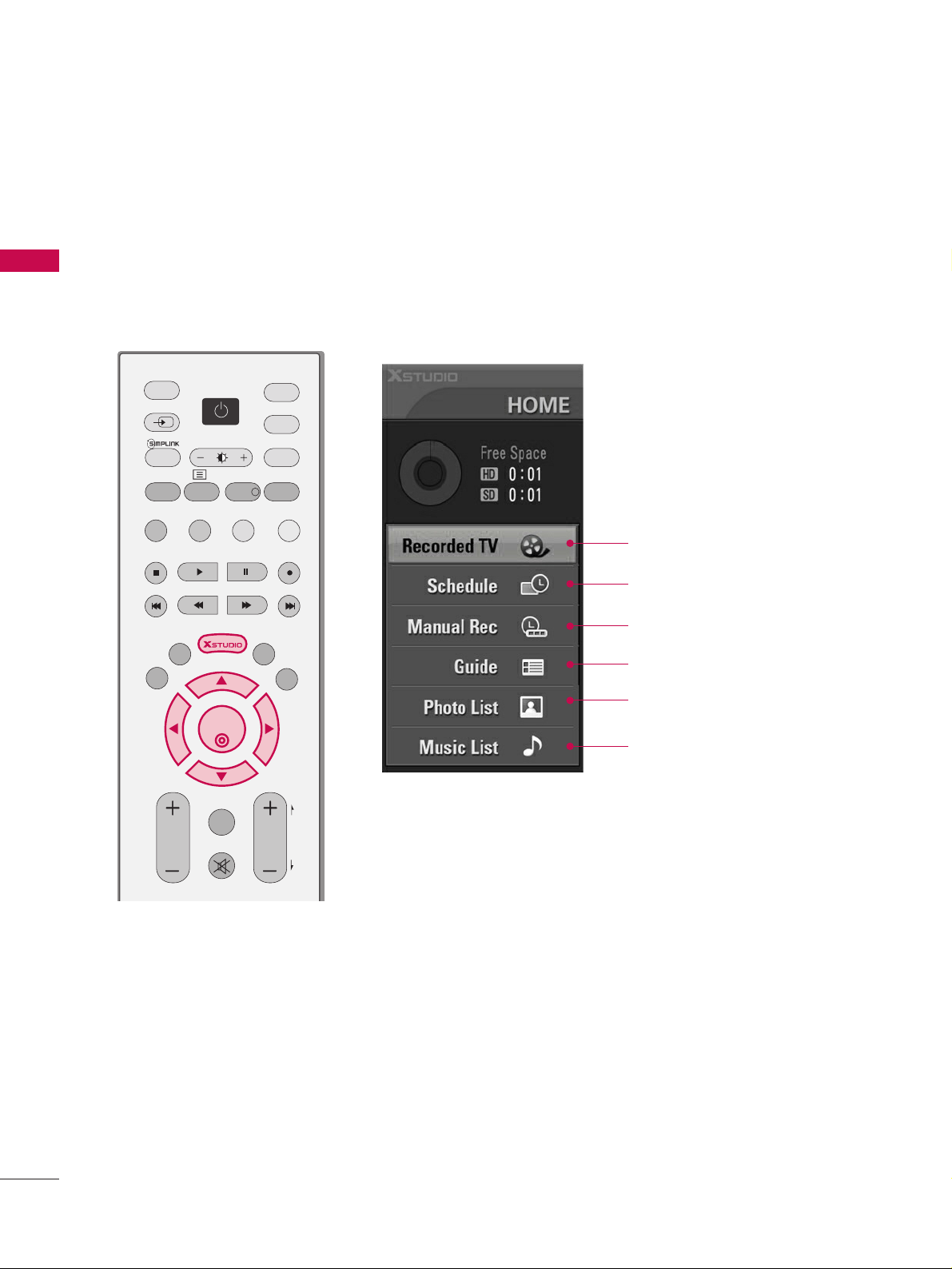
HOME MENU
This menu is a contents guide.
In Home Menu, you enter the Recorded TV and the Guide of X-STUDIO, the X-STUDIO recording schedule,
Manual Recording, Photo List, Music List
TV
DVD
SIMPLINK
EXIT
VOL
Q.VIEW
PR
MARK
LIVE
TEXT
GUIDE
VCR
MODE
BRIGHT
MENU
MUTE
PAG E
INFO
i
PIP PR- PIP PR+
PIP INPUTSWAP
TIME
SHIFT
TIME
SHIFT
PIP
OK
D/A
INPUT
POWER
INPUT
Schedule
GG
pp..5599
Manual Rec
GG
pp..5544
Recorded TV
GG
pp..5555
Guide
GG
pp..7700
Photo List
GG
pp..6633
Music List
GG
pp..6677
Page 7
PREPARATION
5
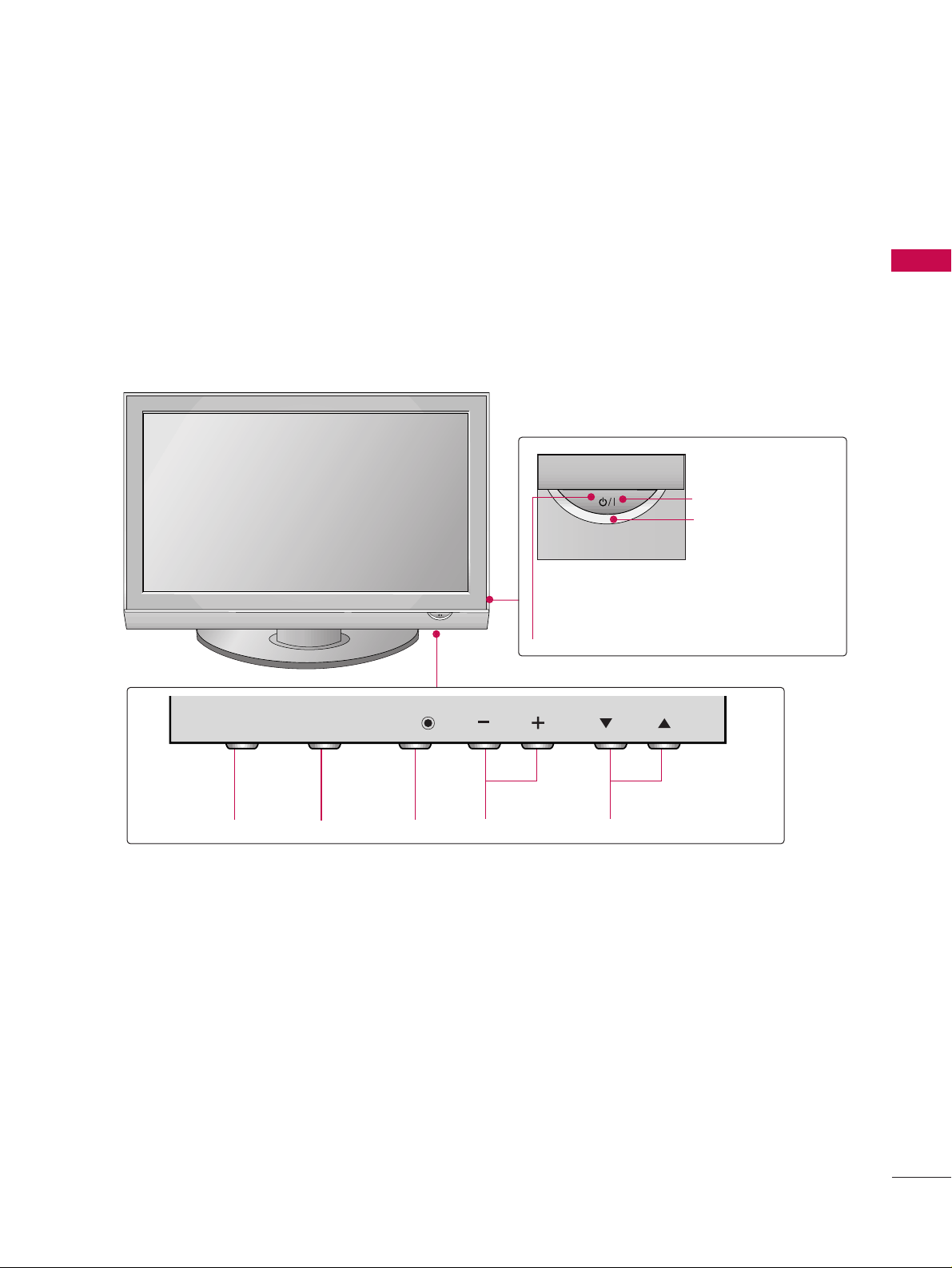
FRONT PANEL CONTROLS
■
Image shown may differ from your TV
■
If your TV has a protection film attached, remove the film and then wipe the product with a polishing cloth.
PROGRAMMEVOLUMEMENU OKINPUT
OKOK
MENUMENU
INPUTINPUT
PRVOLVOL
Remote Control Sensor
POWER Button
Power/Standby Indicator
• illuminates red in standby mode.
• illuminates green when the TV is
switched on.
Page 8
PREPARATION
6
PREPARATION
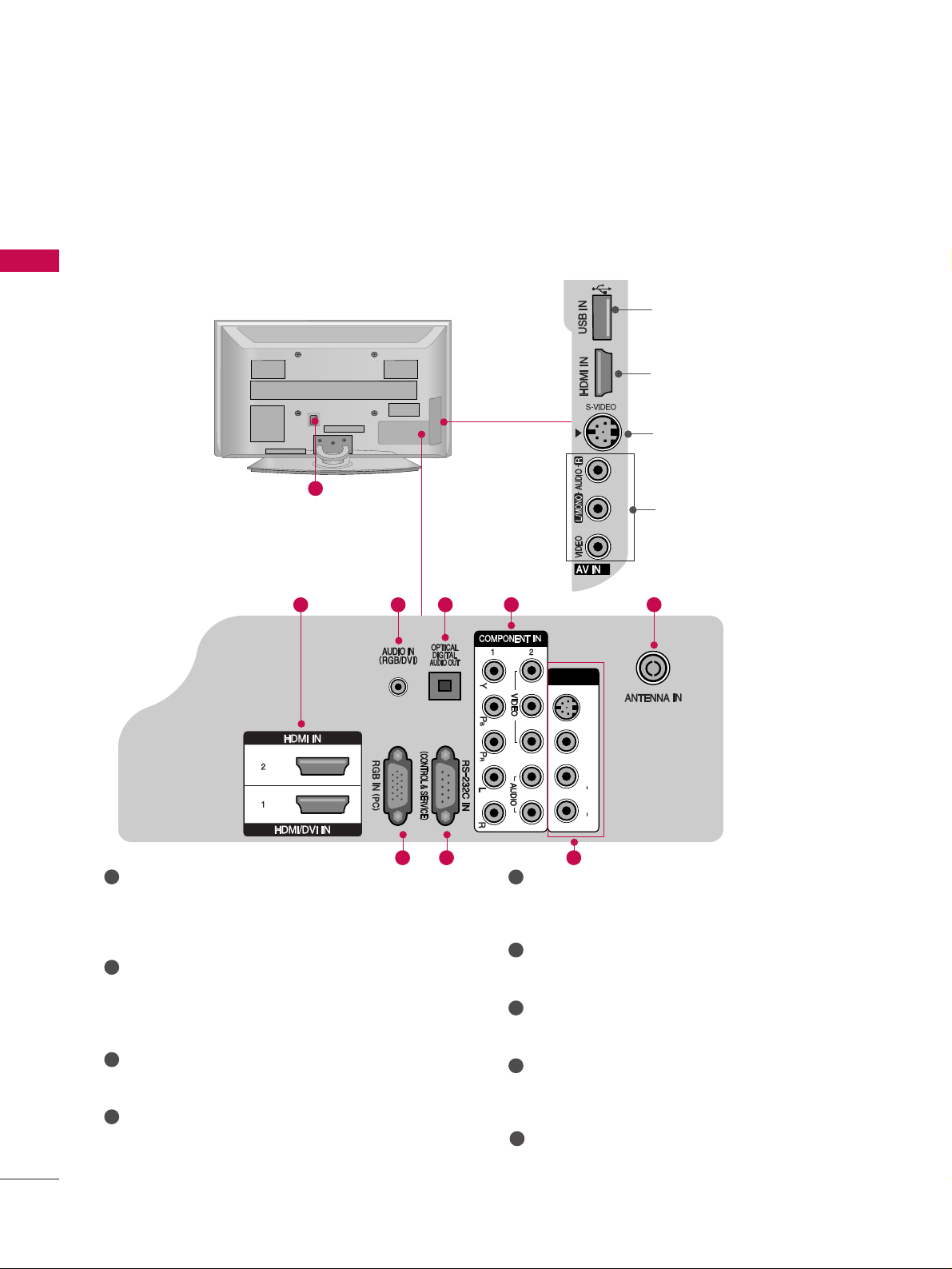
BACK PANEL INFORMATION
■
Image shown may be somewhat different from your TV.
Power Cord Socket
This TV operates on an AC power. The voltage is
indicated on the Specifications page. Never
attempt to operate the TV on DC power.
HDMI Input
Connect a HDMI signal to HDMI IN.
Or DVI(VIDEO)signal to HDMI/DVI port with DVI
to HDMI cable.
RGB/DVI Audio Input
Connect the audio from a PC.
OPTICAL DIGITAL AUDIO OUT
Connect digital audio from various types of equipment.
Note: In standby mode, these ports do not work.
Component Input
Connect a component video/audio device to
these jacks.
RGB Input
Connect the output from a PC.
RS-232C IN (CONTROL & SERVICE) PORT
Connect to the RS-232C port on a PC.
Audio/Video Input (AV IN 1)
Connect audio/video output from an external
device to these jacks.
Antenna Input
Connect RF antenna to this jack.
1
2
3
4
5
6
7
8
1
V IN 1
L/
MONO
AUDIO
VIDEO
S-VIDEO
2 3
4
5
9
8
9
2
3
USB Input
HDMI Input
Connect a HDMI signal
to HDMI IN.
S-Video Input
Connect S-Video out
from an S-VIDEO device.
Audio/Video Input
Connect audio/video
output from an external
device to these jacks.
76
AV IN 1
S-VIDEO
VIDEO
L/
M
ONO
AUDIO
R
Page 9
PREPARATION
7
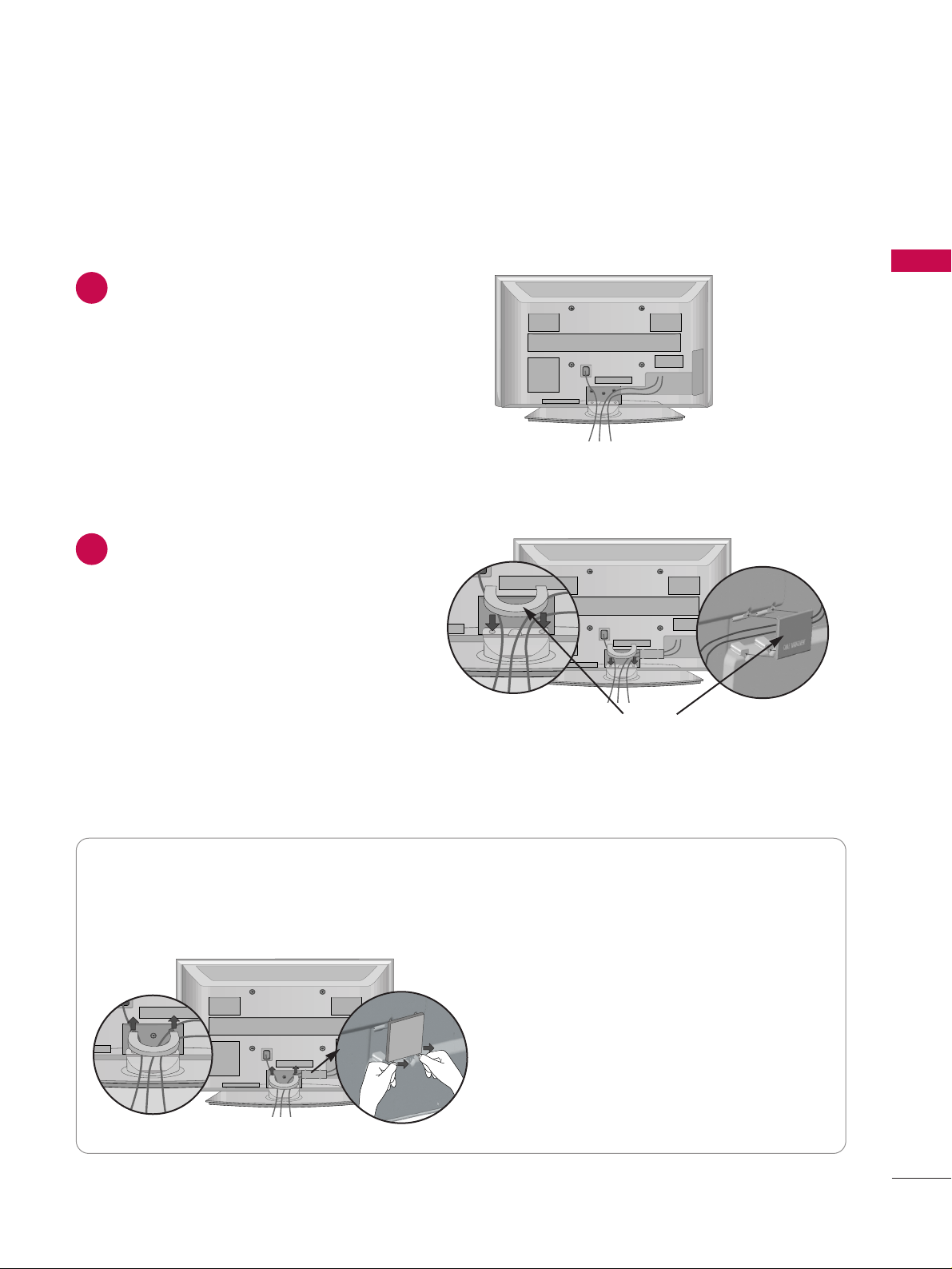
Connect the cables as necessary.
To connect additional equipment, see the
EEXXTTEERR NNAALL EE QQUUIIPPMMEENNTT SS EETT UUPP
section.
1
Install the
CCAABBLLEE MMAANNAAGG EEMMEENNTT CCLLIIPP
as shown.
2
CABLE MANAGEMENT CLIP
Hold the
CCAABBLLEE MMAA NNAAGGEE MMEENNTT CCLLIIPP
with both hands and pull it upward.
How to remove the cable management clip
Separate CABLE MANAGEMENT from TV by
pressing two latches.
BACK COVER FOR WIRE ARRANGEMENT
■
Image shown may be somewhat different from your TV.
Page 10
PREPARATION
8
PREPARATION
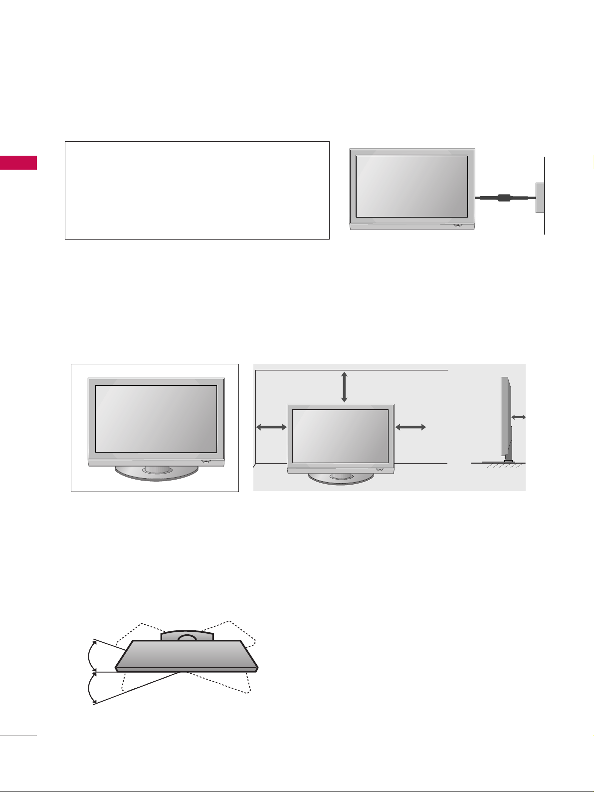
DESKTOP PEDESTAL INSTALLATION
For adequate ventilation allow a clearance of 4” (10cm) all around the TV.
A
The TV can be installed in various ways such as on a wall, or on a desktop etc.
A
The TV is designed to be mounted horizontally.
Power Supply
Circuit breaker
EARTHING
Ensure that you connect the earth wire to prevent possible
electric shock. If grounding methods are not possible, have
a qualified electrician install a separate circuit breaker.
Do not try to earth the TV by connecting it to telephone
wires, lightening rods or gas pipes.
4 inches
4 inches
4 inches
4 inches
SWIVEL STAND
After installing the TV, you can adjust the TV set manually to the left or right direction by 20 degrees to suit
your viewing position.
Page 11
PREPARATION
9
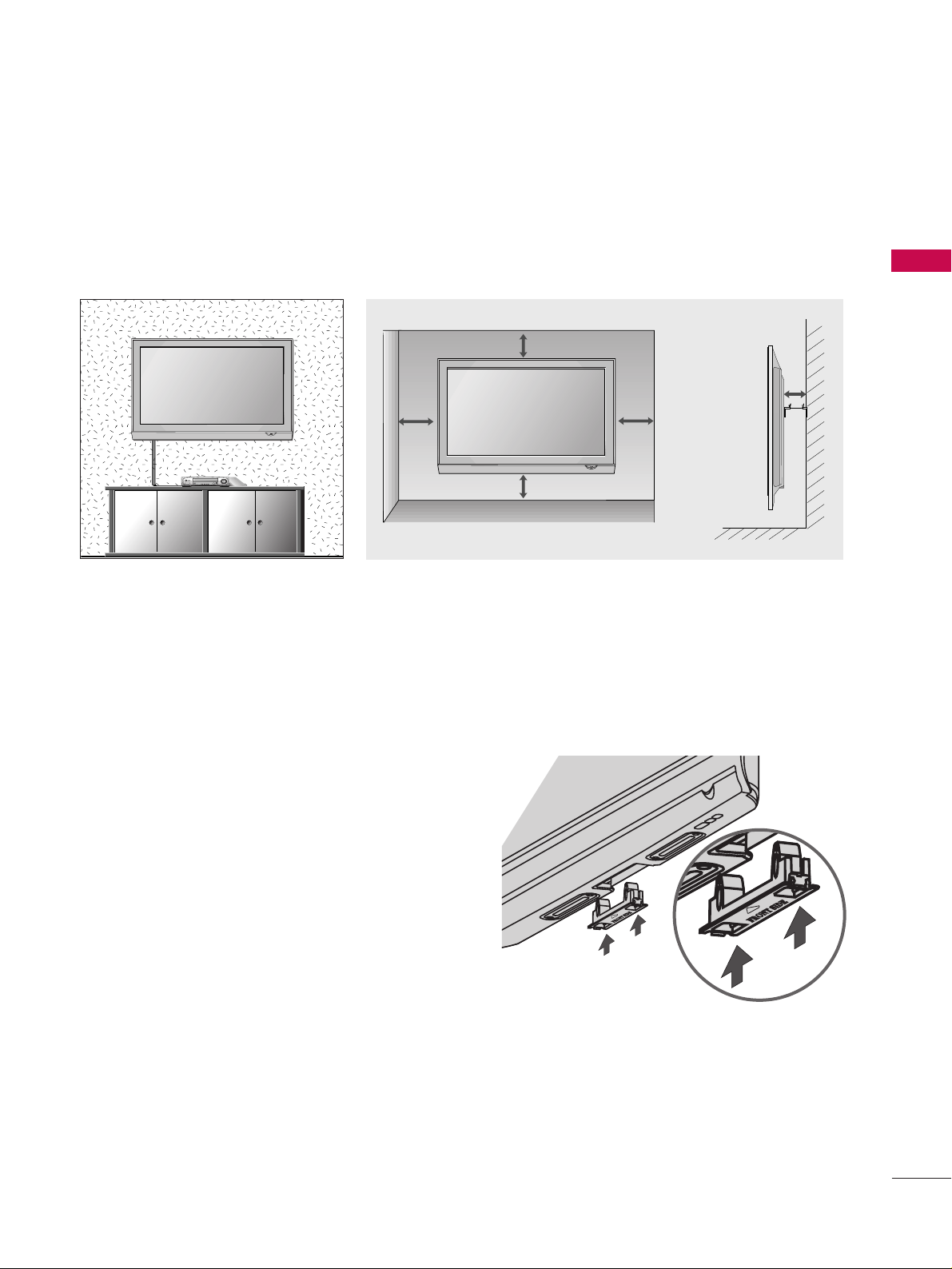
WALL MOUNT: HORIZONTAL INSTALLATION
For adequate ventilation allow a clearance of 4” (10cm) all around the TV. We recommend that you use a
wall mounting bracket of LG brand when mounting the TV to a wall.
4 inches
4 inches
4 inches
4 inches
4 inches
NOT USING THE DESK-TYPE STAND
When installing the wall-mounted unit, use the
protection cover for desk-type stand installation.
Insert the PROTECTION COVER into the TV until
clicking sound.
■
Image shown may differ from your TV.
Page 12
10
PREPARATION
PREPARATION
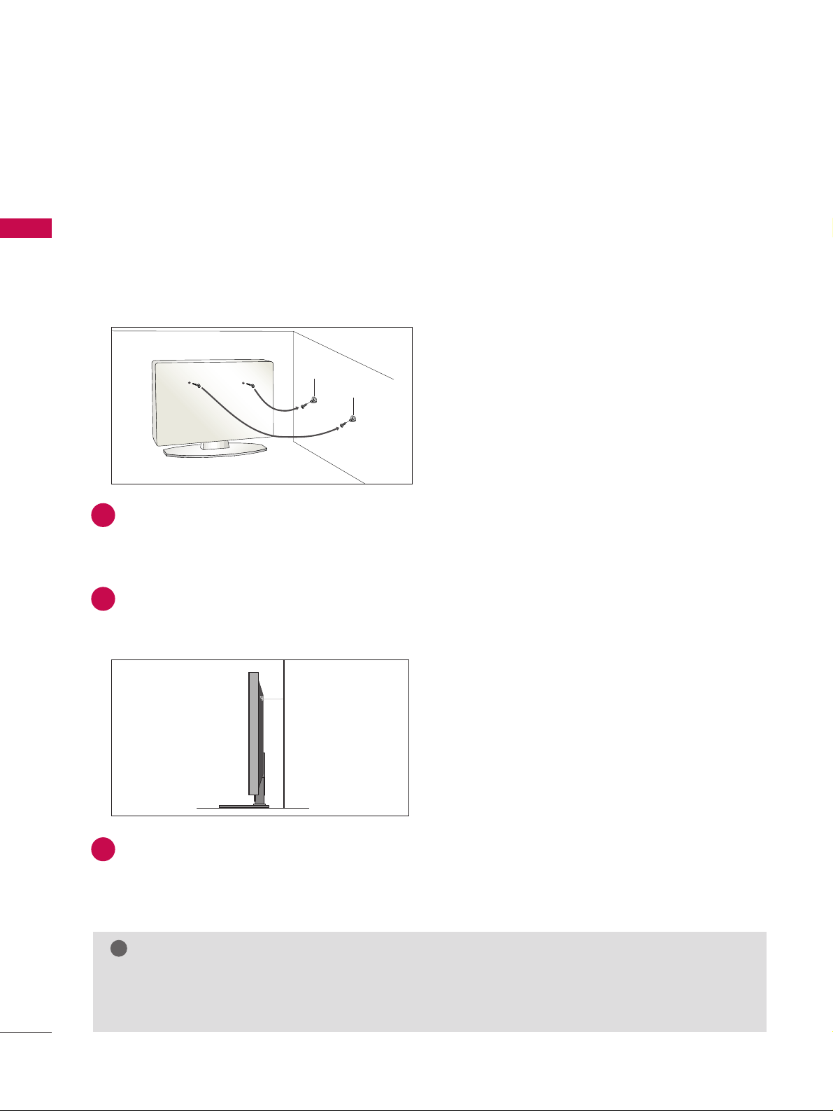
PLEASE SET IT UP CAREFULLY SO THE PRODUCT DOES
NOT FALL OVER.
A
You should purchase necessary components to fix the TV to the wall.
A
Position the TV close to the wall to avoid the possibility of it falling when pushed.
A
The instructions shown below are a safer way to set up the TV, which is to fix it to the wall, avoiding the
possibility of it falling forwards if pulled. This will prevent the TV from falling forward and causing injury.
This will also prevent the TV from damage. Ensure that children do not climb or hang from the TV.
NOTE
!
G
When moving the TV undo the cords first.
G
Use a platform or cabinet strong and large enough to support the size and weight of the TV.
G
To use the TV safely make sure that the height of the bracket on the wall and on the TV is the same.
2
3
1
1
2
Use the eye-bolts or TV brackets/bolts to fix the product to the wall as shown in the picture.
(If your TV has bolts in the eyebolts, loosen then bolts.)
* Insert the eye-bolts or TV brackets/bolts and tighten them securely in the upper holes.
Secure the wall brackets with the bolts on the wall. Match the height of the bracket that is mounted on the
wall.
3
Use a sturdy rope to tie the product. It is safer to tie the rope so it is horizontal between the wall
and the product.
Page 13
PREPARATION
11
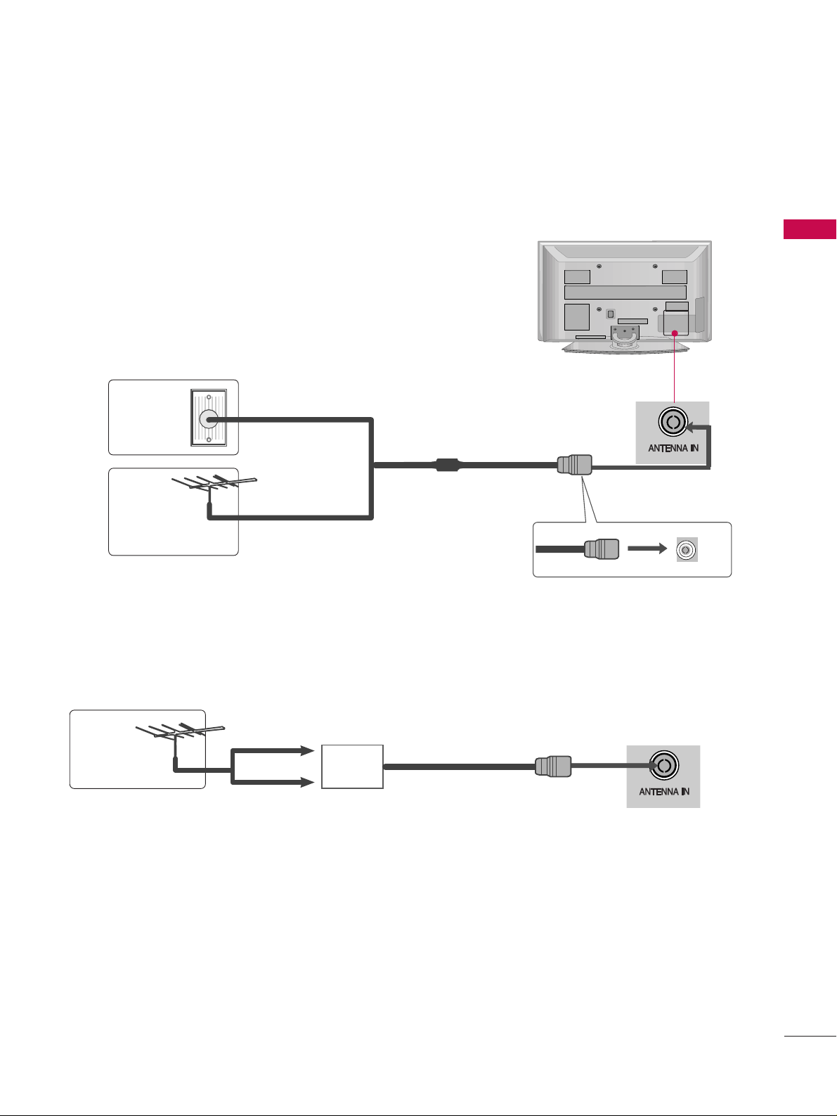
ANTENNA CONNECTION
■
For optimum picture quality, adjust antenna direction.
■
An antenna cable and converter are not supplied.
■
To prevent damage do not connect to the mains outlet until all connections are made between the devices.
Multi-family Dwellings/Apartments
(Connect to wall antenna socket)
Single-family Dwellings /Houses
(Connect to wall jack for outdoor antenna)
Outdoor
Antenna
(VHF, UHF)
Wall
Antenna
Socket
RF Coaxial Wire (75 ohm)
Antenna
UHF
Signal
Amplifier
VHF
■
In poor signal areas, to achieve better picture quality it may be necessary to install a signal amplifier to the
antenna as shown above.
■
If signal needs to be split for two TVs, use an antenna signal splitter for connection.
Page 14
EXTERNAL EQUIPMENT SETUP
12
EXTERNAL EQUIPMENT SETUP
HD RECEIVER SETUP
■
To avoid damaging any equipment, never plug in any power cords until you have finished connecting all equipment.
■
Image shown may differ from your TV.
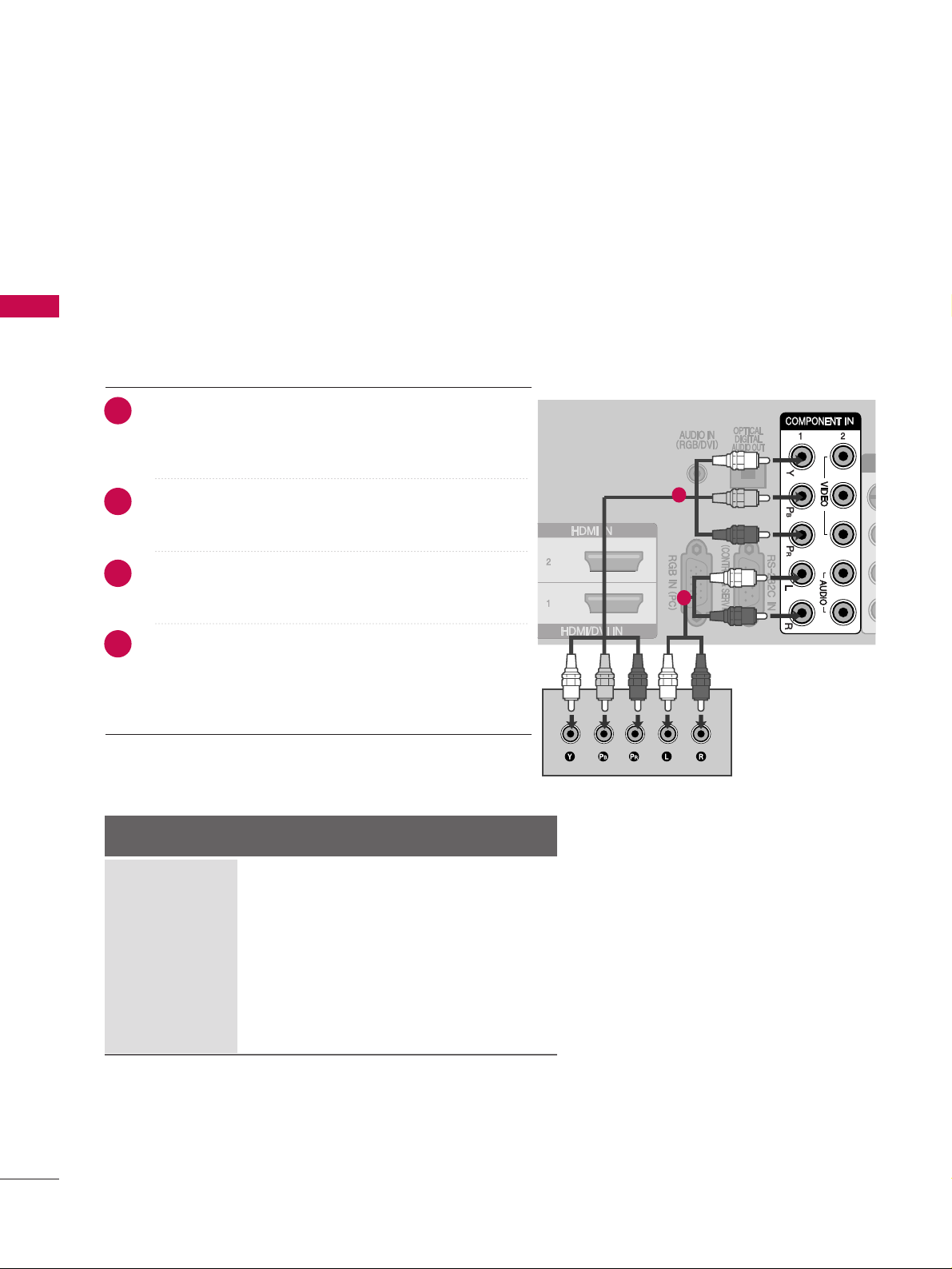
Connecting with a component cables
AAV IN 1
L/ MONO
R
AUDIO
VIDEO
S-VIDEO
1
2
■
This TV can receive Digital RF/Cable signals without an external digital set-top box. However, if you do receive
Digital signals from a digital set-top box or other digital external device, refer to the diagram as shown below.
Connect the video outputs (Y, PB, PR
)
of the digital set
top box to the
CCOO MMPPOONN EENN TT IINN VVIIDDEEOO
jacks on the
TV.
Connect the audio output of the digital set-top box to
the
CCOO MMPPOONN EENN TT IINN AAUUDDIIOO
jacks on the TV.
Turn on the digital set-top box.
(
Refer to the owner’s manual for the digital set-top box.
)
Select
CCoo mmppoonneenntt 11
input source using the
IINNPPUUTT
button on the remote control.
If connected to
CCOO MMPPOONNEE NNTT II NN 22
input, select
CCoo mmppoonneenntt 22
input source.
2
3
4
1
Signal
480i
480p
576i
576p
720p
10 8 0 i
10 8 0 p
Component 1/2
Yes
Yes
Yes
Yes
Yes
Yes
Yes
HDMI 1/2/3
No
Yes
No
Yes
Yes
Yes
Yes
Page 15
EXTERNAL EQUIPMENT SETUP
13
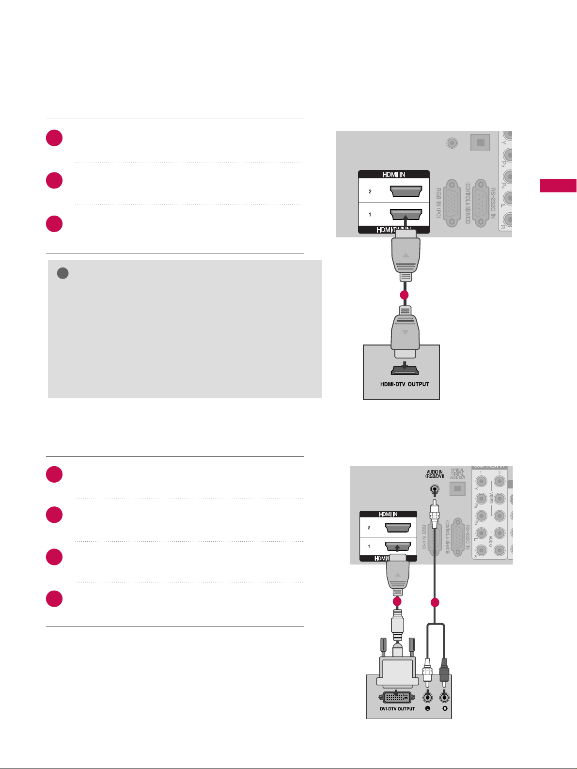
Connecting a set-top box with an HDMI cable
AV IN 1
L/ MONO
R
AUDIO
VIDEO
S-VIDEO
AV IN 1
L/ MONO
R
AUDIO
VIDEO
S-VIDEO
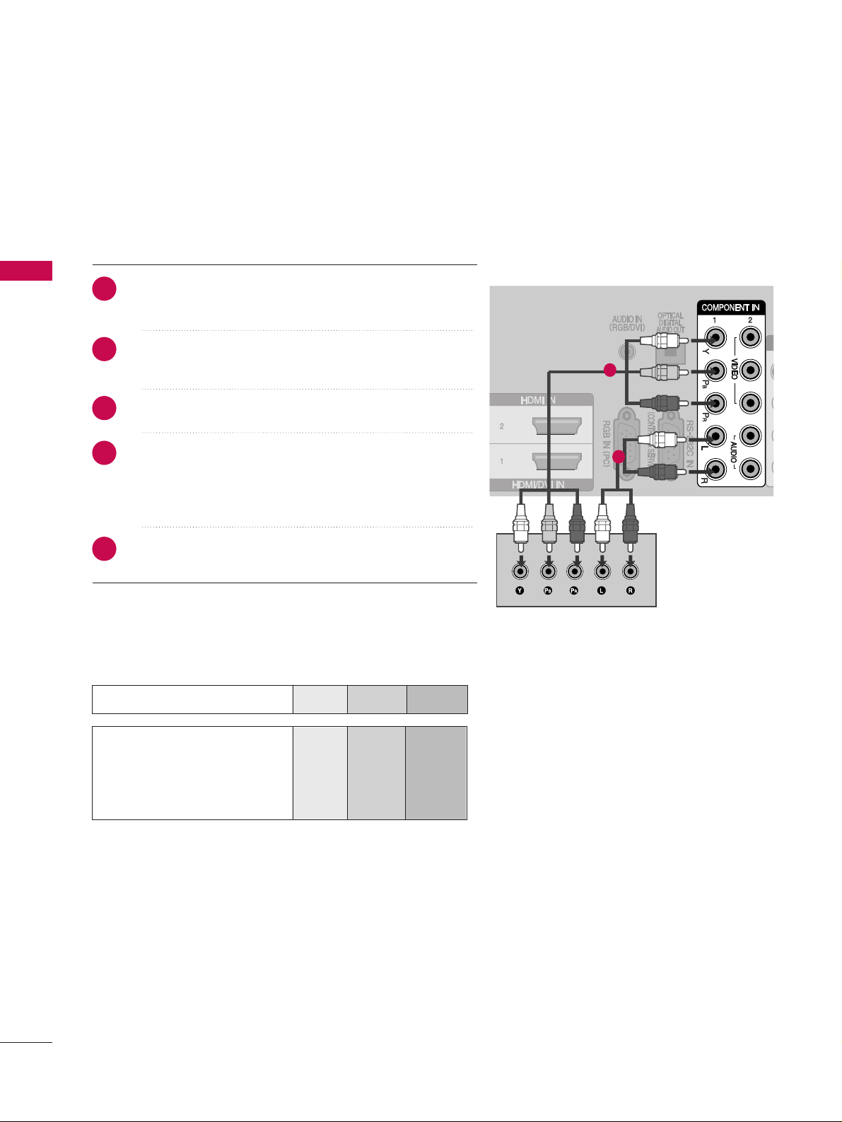
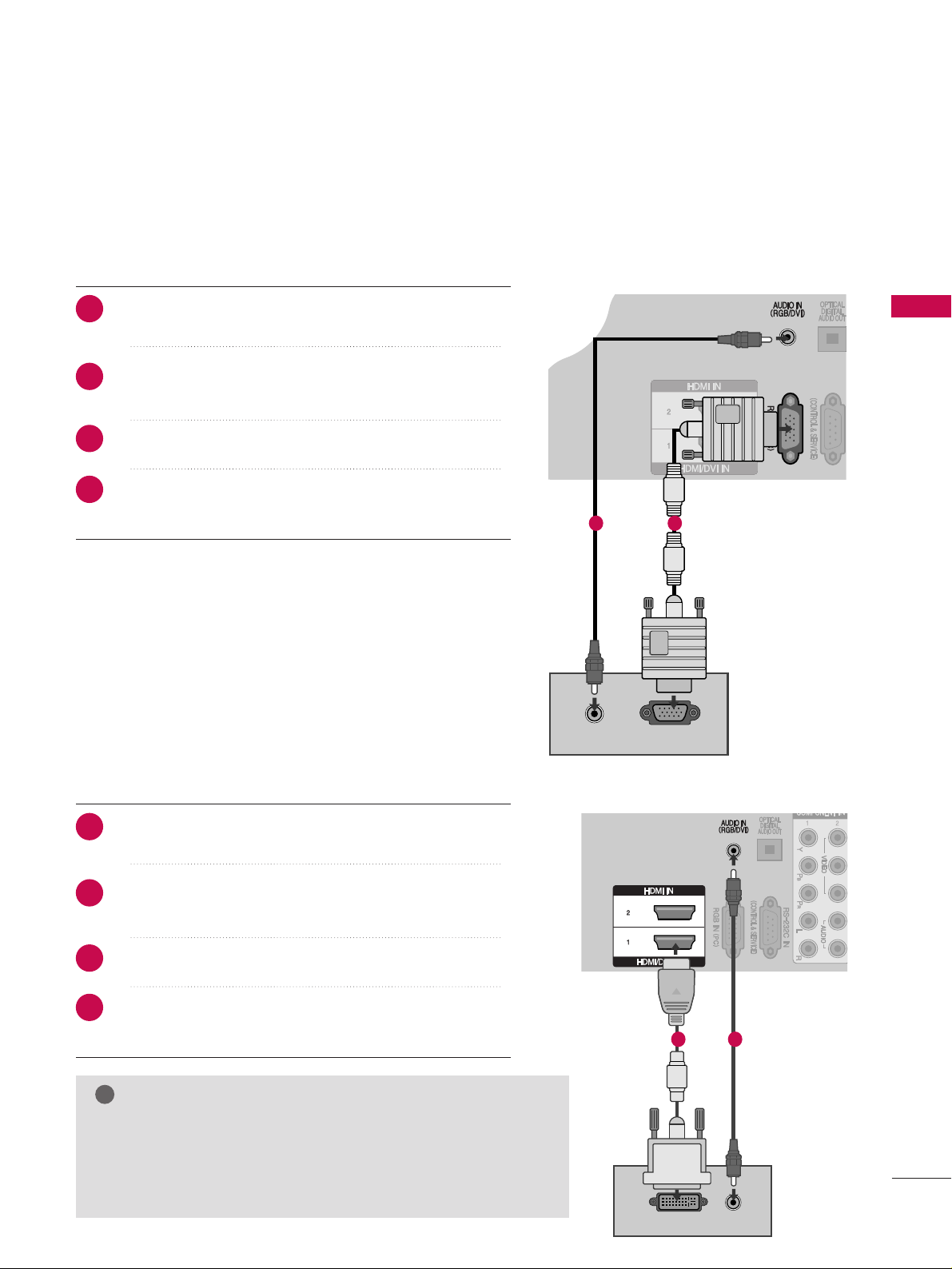
Connecting with an HDMI to DVI cable
AAV IN 1
L/MONO
R
AUDIO
VIDEO
S-VIDEO
Connect the digital set-top box to
HHDDMMII//DDVV II IINN 11
,
HHDDMMII II NN 22
or
HHDDMMII II NN 33
jack on the TV.
Turn on the digital set-top box.
(
Refer to the owner’s manual for the digital set-top box.
)
Select
HHDDMMII11, HHDDMMII 22
or
HHDDMMII 33
input source using
the
IINNPPUUTT
button on the remote control.
Connect the digital set-top box to
HHDDMMII//DDVV II II NN 11
jack on the TV.
Connect the audio output of the digital set-top box to
the
AA UUDDIIOO IINN ((RRGGBB//DD VVII))
jack on the TV.
Turn on the digital set-top box. (Refer to the owner’s
manual for the digital set-top box.
)
Select
HHDDMMII11
input source using the
IINNPPUUTT
button
on the remote control.
1
1
2
2
3
1
2
3
4
1
GG
If the digital set-top box supports Auto HDMI function, the
output resolution of the source device will be automatically
set to 1280x720p.
GG
If the digital set-top box player does not support Auto
HDMI, you need to set the output resolution appropriately.
To get the best picture quality, adjust the output resolution
of the source device to 1920x1080i/1080p.
NOTE
!
Page 16
EXTERNAL EQUIPMENT SETUP
14
EXTERNAL EQUIPMENT SETUP
DVD SETUP
Connecting with a component cables
AAV IN 1
L/ MONO
R
AUDIO
VIDEO
S-VIDEO
Component Input ports
To achieve better picture quality, connect a DVD player to the component input ports as shown below.
Component ports on the TV
YPB PR
Video output ports
on DVD player
Y
Y
Y
Y
PB
B-Y
Cb
Pb
P
R
R-Y
Cr
Pr
Connect the video outputs (Y, P
B, PR
)
of the DVD to the
CCOO MMPPOONN EENN TT IINN VV IIDDEEOO
jacks on the TV.
Connect the audio outputs of the DVD to the
CCOO MMPPOONN EENN TT IINN AAUUDDIIOO
jacks on the TV.
Turn on the DVD player, insert a DVD.
Select
CCoo mmppoonneenntt 11
input source using the
IINNPPUUTT
button on the remote control.
If connected to
CCOO MMPPOONNEE NNTT II NN 22
input, select
CCoo mmppoonneenntt 22
input source.
Refer to the DVD player's manual for operating
instructions.
1
2
2
3
4
1
5
Page 17
EXTERNAL EQUIPMENT SETUP
15
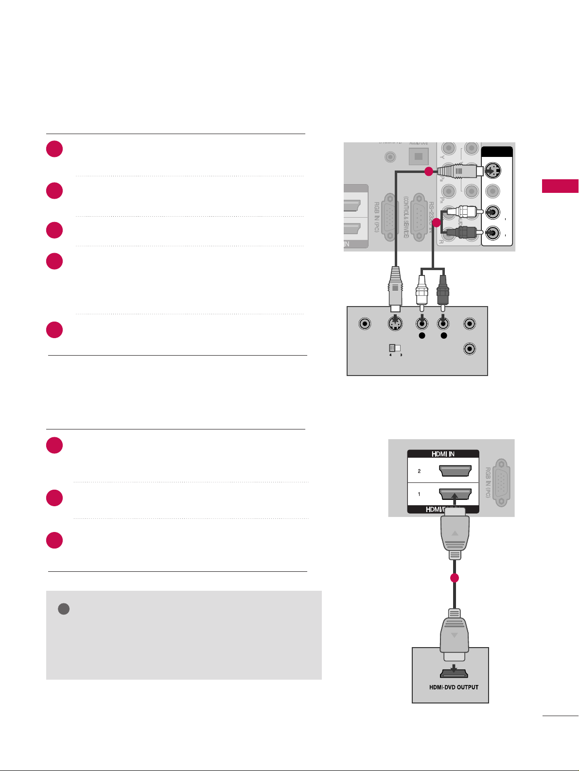
Connecting with a S-Video cable
AV IN 1
L/ MONO
R
AUDIO
VIDEO
S-VIDEO
AV IN 1V IN 1
L/L/M
O
NO
MONO
R
AUDIOAUDIO
VIDEOVIDEO
S-VIDEOS-VIDEO
S-VIDEO
L R
VIDEO ANT IN
OUTPUT
SWITCH
ANT OUT
Connect the S-VIDEO output of the DVD to the
SS --
VVIIDDEE OO
input on the TV.
Connect the audio outputs of the DVD to the
AA UUDDIIOO
input jacks on the TV.
Turn on the DVD player, insert a DVD.
Select
AAVV 11
input source using the
IINNPPUUTT
button on
the remote control.
If connected to
AAVV IINN 22
input, select
AAVV 22
input
source.
Refer to the DVD player's manual for operating
instructions.
AV IN 1
L/ MONO
R
AUDIO
VIDEO
S-VIDEO
Connecting the HDMI cable
Connect the HDMI output of the DVD to the
HHDDMMII//DDVV II IINN 11,HHDDMMII IINN 22orHHDDMMII IINN 33
jack on
the TV.
Select
HHDDMMII11, HHDDMMII22
or
HHDDMMII33
input source using
the
IINNPPUUTT
button on the remote control.
Refer to the DVD player's manual for operating
instructions.
GG
The TV can receive video and audio signals simultaneously
when using a HDMI cable.
GG
If the DVD does not support Auto HDMI, you must set the
output resolution appropriately.
NOTE
!
2
3
4
1
5
2
3
1
1
2
1
Page 18
EXTERNAL EQUIPMENT SETUP
16
EXTERNAL EQUIPMENT SETUP
VCR SETUP
■
To avoid picture noise (interference), allow adequate distance between the VCR and TV.
■
Typically a frozen still picture from a VCR. If 4:3 picture format is used for an extended period the fixed
images on the sides of the screen may remain visible.
AV IN 1
L/L/M
O
N
O
MONO
R
AUDIOAUDIO
VIDEOVIDEO
S-VIDEOS-VIDEO
OUTPUT
SWITCH
ANT IN
R
S-VIDEO VIDEO
ANT OUT
L
Wall Jack
Antenna
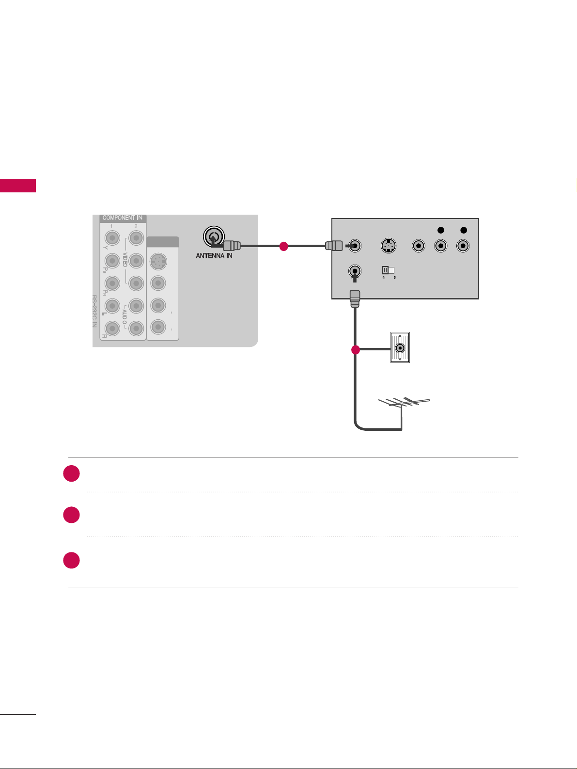
Connecting with a RF Cable
Connect the
AA NNTT OO UUTT
socket of the VCR to the
AA NNTTEENN NNAA IINN
socket on the TV.
Connect the antenna cable to the
AA NNTT IINN
socket of the VCR.
Press the
PP LLAA YY
button on the VCR and match the appropriate channel between the TV and VCR for
viewing.
1
2
2
3
1
Page 19
EXTERNAL EQUIPMENT SETUP
17
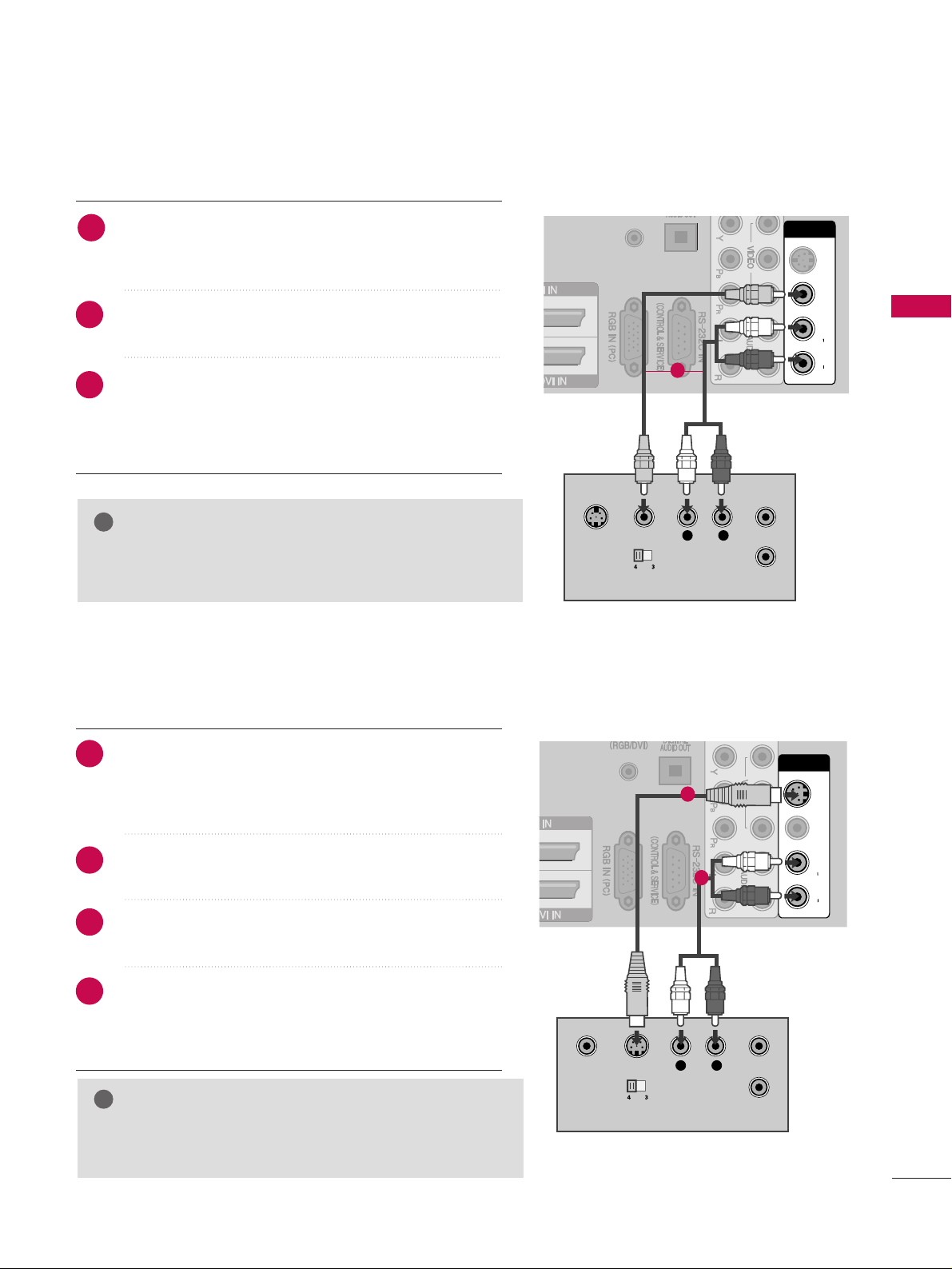
Connecting with an RCA cable
L
R
S-VIDEO
VIDEO
OUTPUT
SWITCH
ANT IN
ANT OUT
AV IN 1
L/ MONO
R
AUDIO
VIDEO
S-VIDEO
AV IN 1V IN 1
L/L/M
O
NO
MONO
R
AUDIOAUDIO
VIDEOVIDEO
S-VIDEOS-VIDEO
2
Connect the
AA UUDDIIOO/VVIIDDEE OO
jacks between TV and
VCR. Match the jack colours (Video = yellow, Audio Left
= white, and Audio Right = red)
Insert a video tape into the VCR and press PLAY on
the VCR. (Refer to the VCR owner’s manual.
)
Select
AAVV 11
input source using the
IINNPPUUTT
button on
the remote control.
If connected to
AAVV IINN 22
input, select
AAVV 22
input
source.
GG
If you have a mono VCR, connect the audio cable from the
VCR to the
AA UUDDII OO LL//MM OONNOO
jack of the TV.
NOTE
!
GG
If both S-VIDEO and VIDEO sockets have been connected to
the S-VHS VCR simultaneously, only the S-VIDEO can be
received.
NOTE
!
AV IN 1
L/ MONO
R
AUDIO
VIDEO
S-VIDEO
AV IN 1V IN 1
L/L/M
ON
O
MONO
R
AUDIOAUDIO
VIDEOVIDEO
S-VIDEOS-VIDEO
S-VIDEO
L R
VIDEO ANT IN
OUTPUT
SWITCH
ANT OUT
Connecting with a S-Video cable
Connect the S-VIDEO output of the VCR to the
SS --
VVIIDDEE OO
input on the TV set. The picture quality is
improved; compared to normal composite (RCA cable)
input.
Connect the audio outputs of the VCR to the
AA UUDDIIOO
input jacks on the TV.
Insert a video tape into the VCR and press PLAY on the
VCR. (Refer to the VCR owner’s manual.)
Select
AAVV 11
input source using the
IINNPPUUTT
button on
the remote control.
If connected to
AAVV IINN 22
input, select
AAVV 22
input
source.
1
2
2
3
1
2
3
4
1
1
Page 20
EXTERNAL EQUIPMENT SETUP
18
EXTERNAL EQUIPMENT SETUP
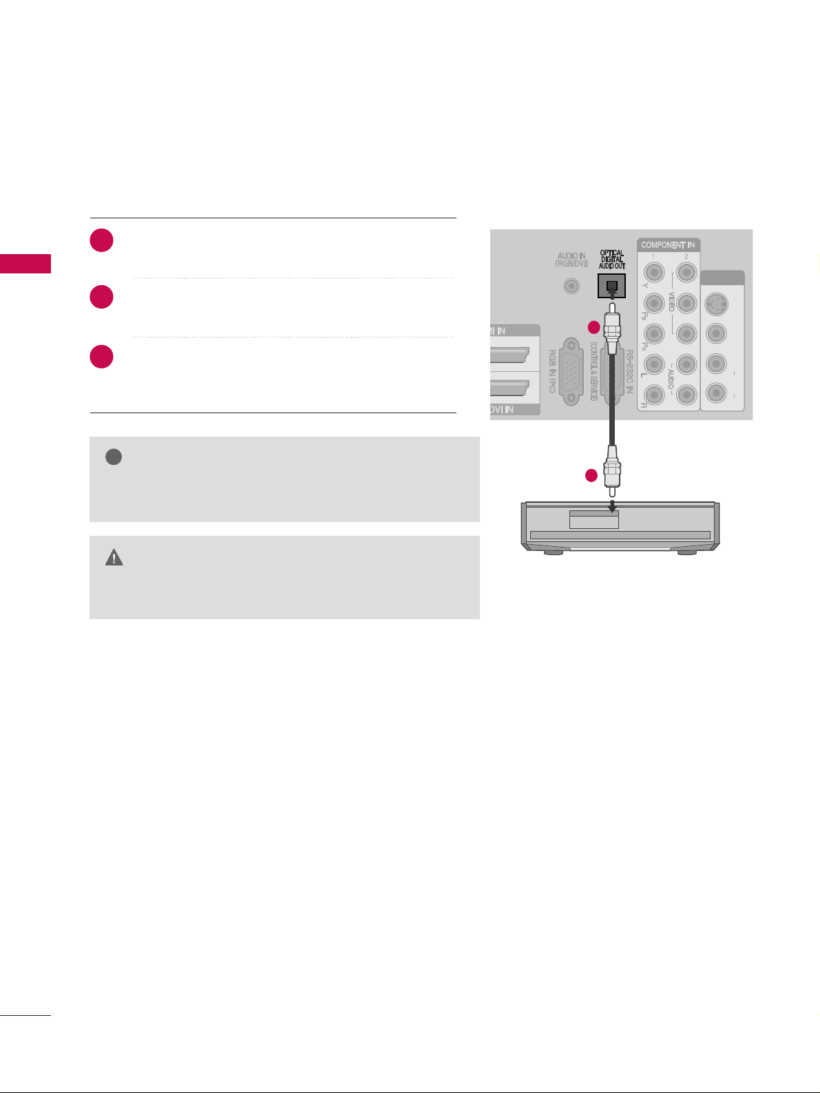
DIGITAL AUDIO OUT SETUP
Sending the TV’s audio signal to external audio equipment via the Digital Audio Output (Optical) port.
AV IN 1V IN 1
L/L/M
ONO
MONO
R
AUDIOAUDIO
VIDEOVIDEO
S-VIDEOS-VIDEO
Connect one end of an optical cable to the TV Digital
Audio (Optical)Output port.
Connect the other end of the optical cable to the
digital audio (optical)input on the audio equipment.
Set the “TV Speaker option - Off ” in the AUDIO
menu.(
G
pp..9933
). Refer to the external audio equipment
instruction manual for operation.
1
2
2
3
1
G
Do not look into the optical output port. Looking at the
laser beam may damage your vision.
CAUTION
GG
When connecting with external audio equipments, such as
amplifiers or speakers, please turn the TV speakers off.
NOTE
!
Page 21

EXTERNAL EQUIPMENT SETUP
19
OTHER A/V SOURCE SETUP
Connect the
AA UUDDIIOO/VVIIDDEE OO
jacks between TV and external equipment. Match the jack colours
.
(
Video = yellow, Audio Left = white, and Audio Right = red
)
Select
AAVV 22
input source with using the
IINNPPUUTT
button on the remote control.
If connected to
AAVV IINN 11
input, select
AAVV 11
input source.
Operate the corresponding external equipment.
Refer to external equipment operating guide.
3
L R
VIDEO
2
Camcorder
Video Game Set
1
2
3
1
Page 22
EXTERNAL EQUIPMENT SETUP
20
EXTERNAL EQUIPMENT SETUP
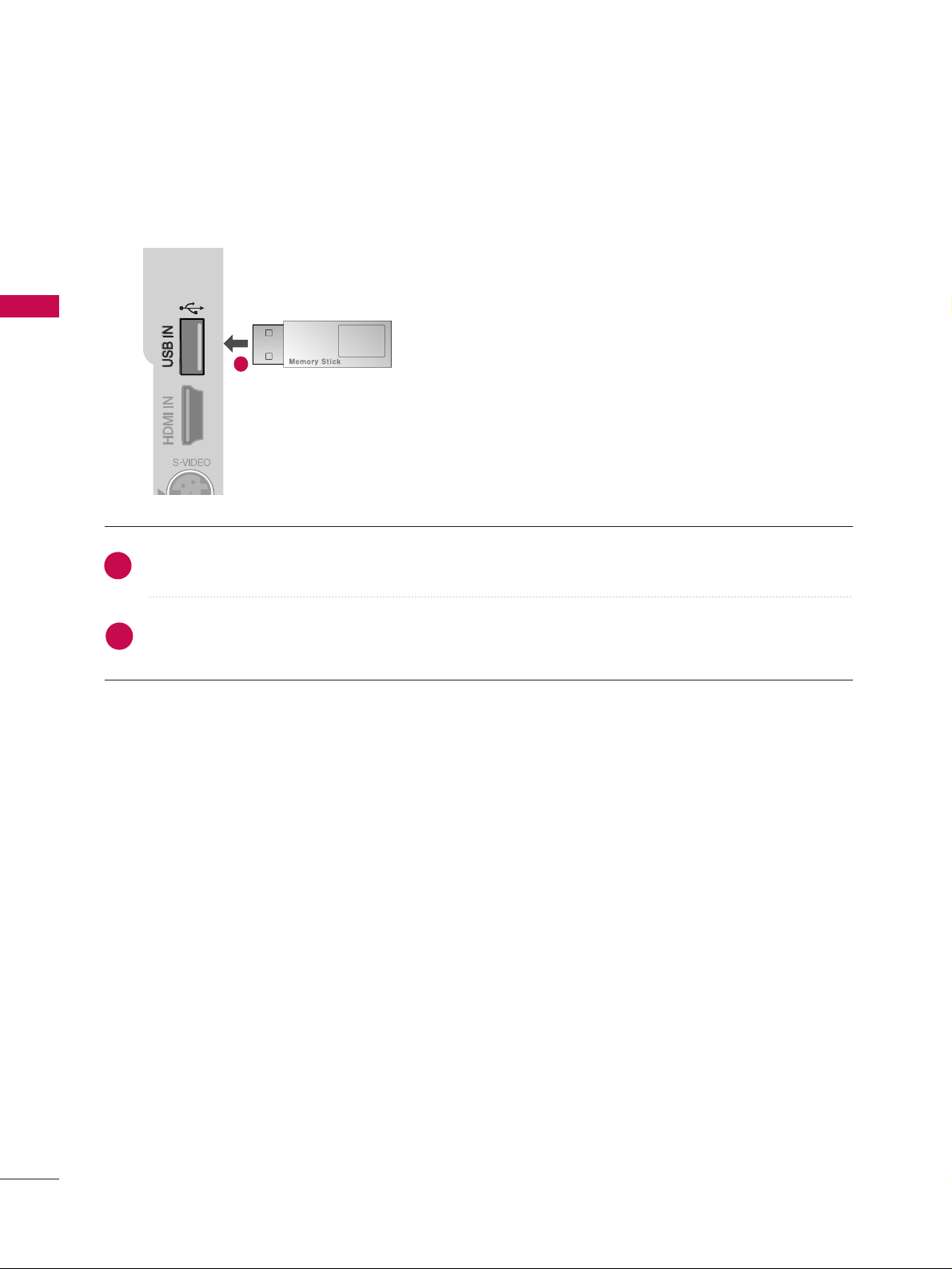
USB IN SETUP
3
Connect the USB device to the
UUSSBB IINN
jacks on the side of TV.
After connecting the
UUSSBB IINN
jacks, you use the
UUSSBB
function. (
GG
pp..6622
)
1
2
1
Page 23
EXTERNAL EQUIPMENT SETUP
21
PC SETUP
This TV provides Plug and Play capability, meaning that the PC adjusts automatically to the TV's settings.
Connecting with a D-sub 15 pin cable
AV IN 1
L/MONO
R
AUDIO
VIDEO
S-VIDEO
AUDIO
RGB OUTPUT
Connect the RGB output of the PC to the
RRGGBB IINN
((PP CC ))
jack on the TV.
Connect the PC audio output to the
AA UUDDII OO II NN
((RRGG BB// DDVVII))
jack on the TV.
Turn on the PC and the TV
Select
RRGGBB -- PPCC
input source using the INPUT button
on the remote control.
AV IN 1
L/MONO
R
AUDIO
VIDEO
S-VIDEO
AV IN 1
L/MONO
R
AUDIO
VIDEO
S-VIDEO
DVI-PC OUTPUT
AUDIO
Connecting with a HDMI to DVI cable
Connect the DVI output of the PC to the
HHDDMMII// DDVVII
IINN11
jack on the TV.
Connect the PC audio output to the
AA UUDDII OO II NN
((RRGG BB// DDVVII))
jack on the TV.
Turn on the PC and the TV.
Select
HHDDMMII11
input source using the INPUT button
on the remote control.
12
1 2
2
3
4
1
2
3
4
1
GG
If the PC has a DVI output and no HDMI output, a separate audio
connection is necessary.
GG
If the PC does not support Auto DVI, you need to set the output
resolution appropriately. To get the best picture quality, adjust the
PC graphics card's output resolution to 1920x1080, 60Hz.
NOTE
!
Page 24

EXTERNAL EQUIPMENT SETUP
22
EXTERNAL EQUIPMENT SETUP
RGB-PC, HDMI/DVI-PC mode
Horizontal Vertical
Frequency(kHz)Frequency(Hz
)
31.469 59.940
37.500 75.000
31.469 70.08
37.879 60.317
46.875 75.000
48.363 60.004
56.476 70.069
60.023 75.029
47.776 59.870
47.712 60.015
47.13 59.65
63.981 60.020
79.976 75.025
75.000 60.000
67.500 60.000
Resolution
720x400
1280x1024
640x480
800x600
1024x768
1280x768
1600x1200
1920x1080
1360x768
1366x768
HDMI/DVI-DTV mode
Horizontal Vertical
Frequency(kHz)Frequency(Hz
)
Resolution
NOTES
!
GG
Depending on the graphics card, DOS mode may not work if a HDMI to DVI Cable is in use.
GG
Avoid keeping a fixed image on the screen for a long period of time. The fixed image may become
permanently imprinted on the screen.
GG
The synchronization input form for Horizontal and Vertical frequencies is separate.
720x480
720x576
1280x720
1920x1080
59.94/60.00
50.00
50.00
59.94/60.00
50.00
23.976/24.00
29.97/30.00
59.94/60.0
50.00
59.94/60.00
31.47/31.50
31.25
37. 50
44.96/45.00
28.125
26.97/27.00
33.716/33.750
33.72/33.75
56.25
67.43/67.50
Page 25

EXTERNAL EQUIPMENT SETUP
23
NOTE
!
G
Avoid keeping a fixed image on the set’s screen for
prolonged periods of time. The fixed image may
become permanently imprinted on the screen; use
a screen saver when possible.
G
Connect the PC to the RGB IN (PC) or HDMI IN
(or HDMI/DVI IN) port of the TV; change the resolution.
G
There may be interference relating to resolution,
vertical pattern, contrast or brightness in PC mode.
Change the PC mode to another resolution or
change the refresh rate to another rate or adjust
the brightness and contrast on the menu until the
picture is clear.
If the refresh rate of the PC graphic card can not be
changed, change the PC graphic card or consult
the manufacturer of the PC graphic card.
G
The synchronization input waveform for Horizontal
and Vertical frequencies are separate.
G
Connect the signal cable from the monitor output
port of the PC to the RGB IN (PC) port of the TV or
the signal cable from the HDMI output port of the
PC to the HDMI IN (or HDMI/DVI IN) port on the
TV.
G
Connect the audio cable from the PC to the Audio
input on the TV. (Audio cables are not included
with the TV).
G
If using a sound card, adjust PC sound as required.
G
This TV uses a VESA Plug and Play Solution. The
TV provides EDID data to the PC system with a
DDC protocol. The PC adjusts automatically when
using this TV.
G
DDC protocol is preset for RGB (Analogue RGB),
HDMI (Digital RGB) mode.
G
If required, adjust the settings for Plug and Play
functionality
G
If the graphic card on the PC does not output analogue and digital RGB simultaneously, connect only
one of either RGB or HDMI IN (or HDMI/DVI IN)
to display the PC output on the TV.
G
If graphic card on the PC does output analogue
and digital RGB simultaneously, set the TV to either
RGB or HDMI; (the other mode is set to Plug and
Play automatically by the TV.)
G
DOS mode may not work depending on the video
card if you use a HDMI to DVI cable.
G
If you use too long an RGB-PC cable, there may be
interference on the screen. We recommend using
under 5m of cable. This provides the best picture
quality.
Page 26

EXTERNAL EQUIPMENT SETUP
24
EXTERNAL EQUIPMENT SETUP
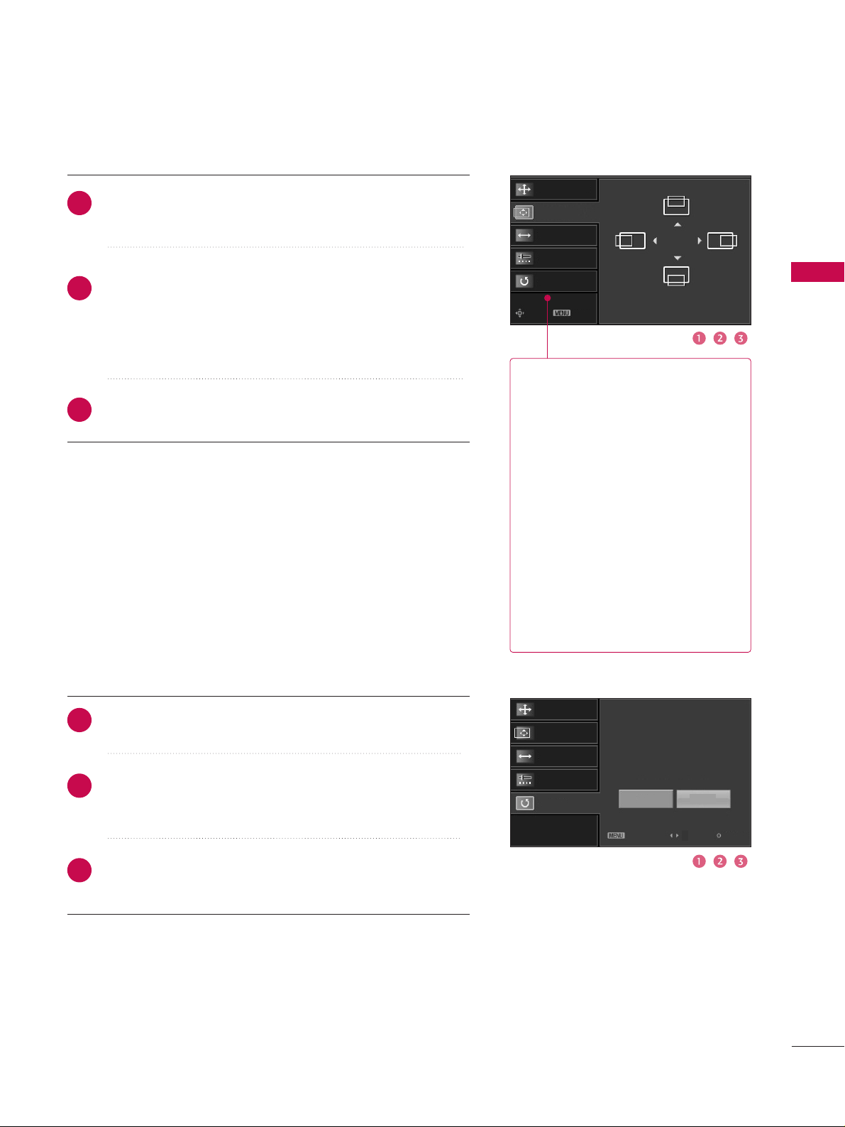
Screen Setup for PC mode
Overview
When the RGB input, of the set is connected to a PC Output, Select
RGB-PC with using the
IINNPPUUTT
button on the remote control.
When you change the resolution, select the proper resolution in
present input to see the best picture appearance.
Picture Mode
Colour Temperature
XD
Advanced
Aspect Ratio
Picture Reset
Screen
G
Selection ( Gor ) leads you to
thescreen adjustment menu.
Picture Mode : User1
Colour Temperature : Cool
XD
Advanced
Aspect Ratio : 16:9
Picture Reset
Screen
Press the
MMEENNUU
button and then useDDor EEbutton
to select the
PPIICCTTUURREE
menu.
Press the
GG
button and then useDDor EEbutton to
select
SSccrreeeenn
.
Press the
GG
button to enter the screen adjustment
menu.
2
3
1
Page 27
EXTERNAL EQUIPMENT SETUP
25
Resolution
Position
GG
Clock
Phase
Reset
Move Prev
Resolution
Position
Clock
Phase
Reset
GG
Initialize Settings.
Yes
No
Prev
Select
OK
RReessoolluuttiioonn
XGA, WXGA(1024(XGA), 1280,
1360, 1366(WXGA))
isn’t distinguished because of
having the same H/V Sync Time.
This function is you to select the
Default Sync Time.
PPoossiittiioonn
This function is to adjust picture
to left/right and up/down as you
prefer.
CClloocckk
This function is to minimize any
vertical bars or stripes visible on
the screen background. And the
horizontal screen size will also
change.
PPhhaassee
This function allows you to
remove any horizontal noise and
clear or sharpen the image of characters.
Use DDor EEbutton to select
RReessoolluuttiioonn, PPoossiittiioonn, CClloocckk
,
or
PPhhaassee
.
Press the
OOKK
button and then use
DD
or EEor
FF
or
GG
button to make appropriate adjustments.
■
The
PPhhaassee
adjustment range is
--1166~++1166
.
■
The
CClloocckk
adjustment range is
--3300~++3300
.
Press the
OOKK
button.
Adjustment for screen Resolution, Position, Clock, Phase, Reset
Use DDor EEbutton to select
RReesseett
.
Press the
OOKK
button and then use
FF
or GGbutton to
select
YYeess
.
Press the
OOKK
button.
Initializing (Reset to original factory values
)
2
3
1
2
3
1
To initialize the adjusted values.
This function allows you to return to the good picture reproduc-
tion programmed at the factory and cannot be change.
Page 28
WATCHING TV/PROGRAMME CONTROL
26
WATCHING TV /PROGRAMME CONTROL
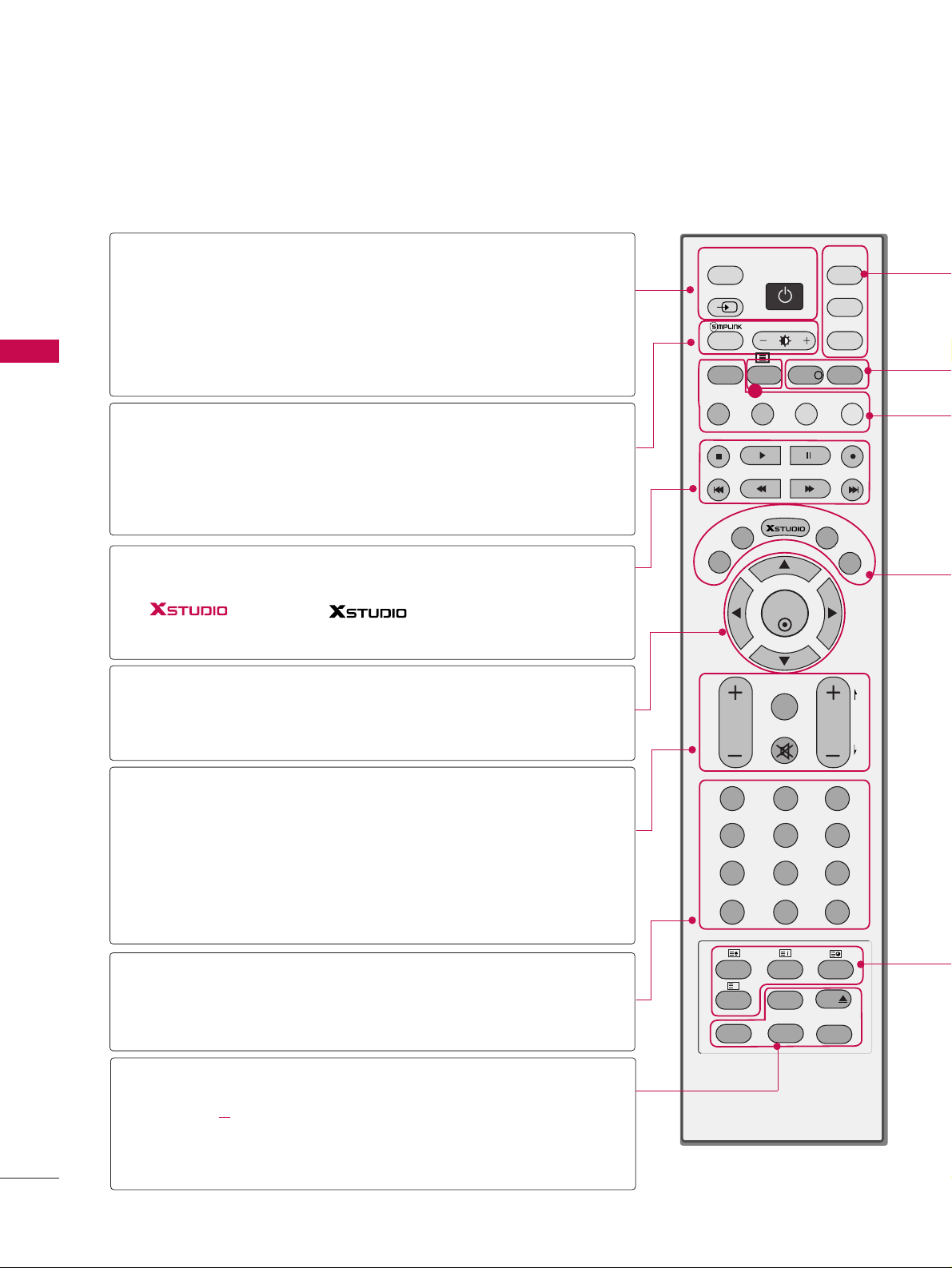
REMOTE CONTROL KEY FUNCTIONS
When using the remote control, aim it at the remote control sensor on the TV.
OK
TVD/A
INPUT
DVD
SIMPLINK
EXIT
VOL
SIZE
INDEX
TIME
REVEAL
Q.VIEW
PR
MARK
LIVE
I/II
PIP
TEXT
GUIDE
VCR
POWER
123
456
789
0
LIST
?
MODE
BRIGHT
MENU
MUTE
INPUT
FAV
SLEEP
PAGE
USB
i
INFO
i
PIP PR- PIP PR+
PIP INPUTSWAP
TIME
SHIFT
TIME
SHIFT
SUBTITLE
RATIO
VCR/DVD
control buttons
1
D/A INPUT
(Digital TV /
Analogue TV)
INPUT
POWER
SIMPLINK
BRIGHT
mode control
buttons
THUMBSTICK
(Up/Down/Left
Right)
(TIME SHIFT)
OK
VOLUME
UP/DOWN
Q.VIEW
MUTE
PROGRAMME
UP/DOWN
PAGE UP/DOWN
NUMBER button
LIST
FAV(FAVORITE)
I/II
USB
DD
SLEEP
SUBTITLE
RATIO
Selects digital or analogue mode.
External input modes rotate in regular sequence: Digital,
Analogue, AV1-2, Component 1-2, RGB-PC, HDMI1,
HDMI2, HDMI3.
Switches the set between ON and STANDBY.
See a list of AV devices connected to TV.
When you toggle this button, the Simplink menu appears
at the screen
GG
p.45-46
Adjusts brightness on screen.
It returns to the default settings brightness by changing
mode source.
Control some video cassette recorders or DVD players
("RECORD" button is not available for DVD player).
Control the mode.
Adjusts menu settings.
Selects menu item.
Accepts your selection or displays the current mode.
Increase/decrease the sound level.
Returns to the previously viewed programme.
Switches the sound on or off.
Select a programme.
Move from one full set of screen information to the next
one.
Selects a programme. Selects numbered items in a menu.
Displays the programme table.
Displays the selected favourite programmes.
Selects the sound output or the audio mode.
Remove the USB device.
Sets the sleep timer.
Recalls your preferred subtitle in digital mode.
Selects your desired picture format.
Page 29
WATCHING TV/PROGRAMME CONTROL
27
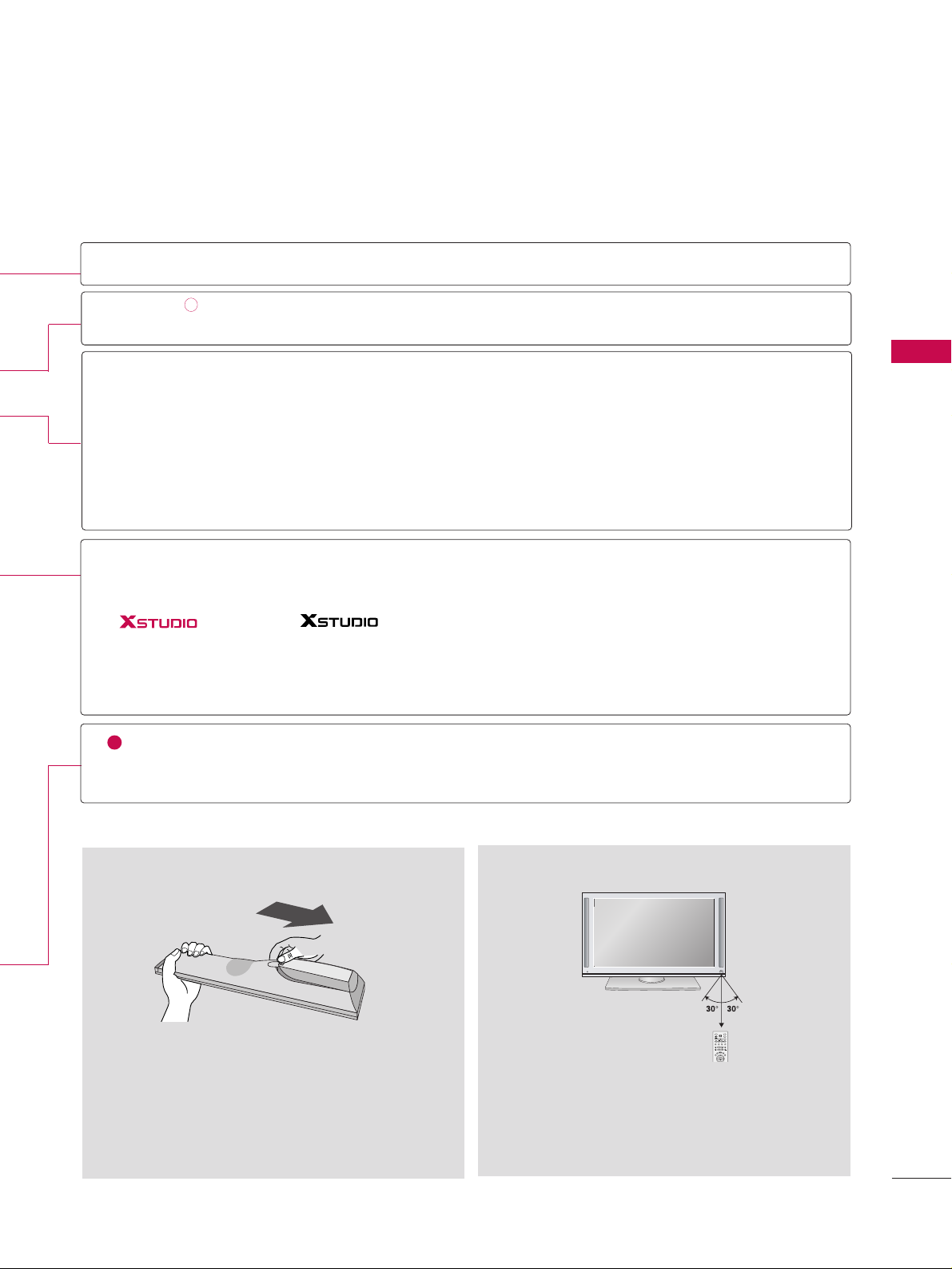
■
Open the battery compartment cover on the back
side and install the batteries matching correct
polarity (+with +,-with -).
■
Install two 1.5V AA batteries. Don’t mix old or
used batteries with new ones.
■
Close cover.
■
Use a remote control up to 7 meters distance and
30 degree (left/right) within the receiving unit
scope.
■
Dispose of used batteries in a recycle bin to
preserve environment.
Installing Batteries
Remote control effective range
TV, VCR, DVD
INFOoo
GUIDE
PIP
PIP PR +/-
SWAP
PIP INPUT
Coloured
Button
EXIT
MENU
LIVE
MARK
TELETEXT
BUTTONS
1
i
Select the remote operating mode: TV, VCR, DVD. Select other operating modes, for the
remote to operate external devices.
Shows the present screen information.
Shows a programme schedule.
Switches to PIP and DW modes or off mode.
Selects a programme for the sub picture.
Alternates between main and sub picture in PIP/DW mode.
Selects the input mode for the sub picture.
They are used as per the indications or functions displayed on the TV screen in the case of
Text displays (Teletext, EPG) and programme edit.
Returns to TV viewing from any menu.
Selects a menu.
Enter to the mode.
In delayed mode, the screen returns to Live programme from TV, AV1 and AV2 modes.
Selects the wanted functions.
These buttons are used for teletext.
Text button is used to enable teletext services while other buttons are for teletext functions.
* For further details, see the ‘Teletext’ section.
i
INPUT
MODE
TVD/A
POWER
INPUT
VCR
BRIGHT
SIMPLINK
DVD
i
PIP
INFO
GUIDE
TEXT
PIP PR-PIP PR+
PIP INPUTSWAP
MENU
LIVE
EXIT
MARK
OK
TIME
TIME
SHIFT
SHIFT
Page 30
If your TV will be turned on, you will be able to use its features.
TURNING ON THE TV
WATCHING TV/PROGRAMME CONTROL
28
WATCHING TV/PROGRAMME CONTROL
INITIALIZING SETUP
If the OSD (On Screen Display) is displayed on the screen
as figure 1 after turning on the set, you can adjust the Auto
Programme tuning, Time Zone selection or Password setting.
1
Welcome
Thank you for choosing LG.
The Following process guides you to complete
initial settings.
Before starting, be sure that the TV antenna
is connected.
Press OK( ) to continue.
Installation Guide
Next
Figure 1.
GG
It will automatically disappear after approx, 40 seconds
unless a button is pressed.
NOTE
!
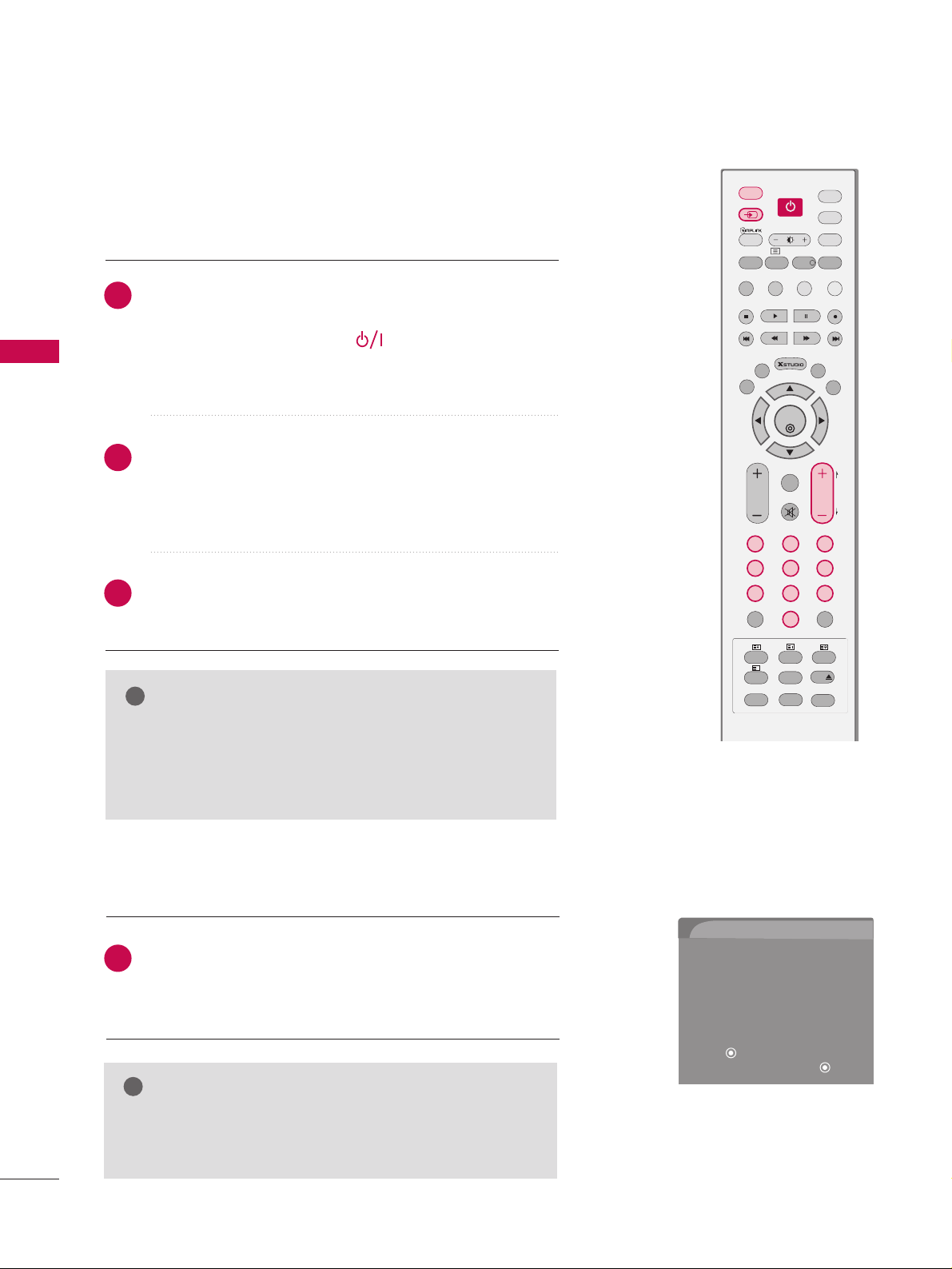
NOTE
!
GG
If you intend to be away on vacation, disconnect the
power plug from the wall power outlet.
GG
When the TV is turned on, the indicator will blink red
before the picture is seen.
Ensure the power cord is connected correctly.
When connected to power the TV switches to standby mode.
■
In standby mode, press the ,
IINNPPUUTT,PPRR
DD
or EEbut-
ton on the TV or press the
PPOOWWEERR, IINNPPUUTT, DD//AA IINNPPUUTT
,
PPRR ++or--, NNuummbbeerr ((00~99))
button on the remote control.
Select the viewing source by using the
IINNPPUUTT
button on
the remote control.
■
This TV is programmed to remember which mode it was
last set to, even if you turn the TV off.
When finished using the TV, press the
PPOOWWEERR
button on
the remote control. The TV reverts to standby mode.
1
2
3
TV
DVD
SIMPLINK
EXIT
VOL
SIZE
INDEX
TIME
REVEAL
Q.VIEW
PR
MARK
LIVE
I/II
TEXT
GUIDE
VCR
123
456
789
0
LIST
?
MODE
BRIGHT
MENU
MUTE
FAV
SLEEP
PAGE
USB
INFO
i
PIP PR- PIP PR+
PIP INPUTSWAP
TIME
SHIFT
TIME
SHIFT
SUBTITLE
RATIO
PIP
OK
D/A
INPUT
POWERPOWER
INPUT
Page 31

VOLUME ADJUSTMENT
WATCHING TV/PROGRAMME CONTROL
29
Press the
PPRR ++
or
--
or
NNUUMMBBEERR
buttons to select a
programme number.
Automatically finds all programmes available through
antenna inputs, and stores them in memory on the programme list.
1
Press the
VVOOLL ++
or
--
button to adjust the volume.
If you want to switch the sound off, press the
MMUUTTEE
button.
You can cancel the Mute function by pressing the
MMUUTTEE
,
II// II II
or
VVOOLL ++
or --button.
Adjust the volume to suit your personal preference.
1
2
3
PROGRAMME SELECTION
VOL
SIZE
INDEX
TIME
REVEAL
Q.VIEW
PR
I/II
123
456
789
0
LIST
?
MUTE
FAV
SLEEP
PAGE
USB
SUBTITLE
RATIO
POWER
TV
DVD
SIMPLINK
EXIT
VOL
SIZE
INDEX
TIME
REVEAL
Q.VIEW
PR
MARK
LIVE
I/II
TEXT
GUIDE
VCR
123
456
789
0
LIST
?
MODE
BRIGHT
MENU
MUTE
FAV
SLEEP
PAGE
USB
INFO
i
PIP PR- PIP PR+
PIP INPUTSWAP
TIME
SHIFT
TIME
SHIFT
SUBTITLE
RATIO
PIP
OK
D/A
INPUT
POWER
INPUT
Page 32

WATCHING TV/PROGRAMME CONTROL
30
WATCHING TV/PROGRAMME CONTROL
ON-SCREEN MENUS SELECTION AND ADJUSTMENT
Press the
MMEENNUU
button and then use DDor EEbutton to select each menu.
Press the
GG
button and then use DDor
EE
or FFor
GG
button to display the available menus.
Your TV's OSD (On Screen Display)may differ slightly from what is shown in this manual.
SETUP
PICTURE
TIME
Auto Tuning
Manual Tuning
Programme Edit
Booster
2
1
AUDIO
Picture Mode : Dynamic
Colour Temperature
XD
Advanced
Aspect Ratio : Auto
Picture Reset
Screen
Sound Mode : Standard
Auto Volume : On
Balance : 0
TV Speaker : On
Clock
Off Time
On Time
Sleep Time
Auto Sleep
TimeShift Mode : On
Record Quality : High
Recorded TV
Schedule List
Manual Record
HDD Format
USB Format
Lock System
Set Password
Block Programme
Parental Guidance
Input Block
DVR
LOCK
Subtitle
Input Label
SIMPLINK
Key Lock
Set ID
ISM Method
Low Power
Factory Reset
Model Info
OPTION
Page 33

WATCHING TV/PROGRAMME CONTROL
31
Subtitle : Off
Input Label
SIMPLINK : Off
Key Lock : Off
Set ID : 1
ISM Method : Normal
Low Power : Off
Factory Reset
Model Info
Subtitle
Input label
SIMPLINK
Key Lock
Set ID
ISM Method
Low Power
Factory Reset
G
Model Info
Off
On
Press the
MM EENNUU
button and then use
DD
or
EE
button to select the
OOPP TTIIOONN
menu.
Press the
GG
button and then use
DD
or
EE
button
to select
Factory Reset
.
Press the
GG
button and then use
DD
or
EE
button
to select
OOnn
or
OOffff
.
Press
EEXXIITT
button to return to normal TV viewing
or press
MMEENNUU
button to return to the previous
menu.
Use to quickly reset all the menu options to their original
factory preset values.
This function deletes all TV programmes.
To begin Factory Reset, input a 4-digit password in Lock
system. Be sure to remember this number!
If you forgot your password, press ‘77’, ‘77’, ‘77’, ‘77’ on the
remote control handset.
2
3
4
1
FACTORY RESET
Selection(ON) resets all
users settings.
WARNING: All channel service and user settings will
be lost and return to initial
setting.
OK
TVD/A
INPUT
DVD
SIMPLINK
EXIT
MARK
LIVE
TEXT
GUIDE
VCR
POWER
MODE
BRIGHT
MENU
INPUT
INFO
i
PIP PR- PIP PR+
PIP INPUTSWAP
TIME
SHIFT
TIME
SHIFT
PIP
POWER
Page 34

WATCHING TV/PROGRAMME CONTROL
32
WATCHING TV/PROGRAMME CONTROL
Subtitle :
Off
Input Label
SIMPLINK : Off
Key Lock : Off
Set ID : 1
ISM Method : Normal
Low Power : Off
Factory Reset
Model Info
Subtitle
Input label
SIMPLINK
Key Lock
Set ID
ISM Method
Low Power
Factory Reset
Model Info
G
MODEL : 50PG79ED-AF
S/W Ver. : 3.00.00
Press the
MM EENNUU
button and then use
DD
or
EE
button to select the
OOPP TTIIOONN
menu.
Press the
GG
button and then use
DD
or
EE
button
to select
Model Info
.
Press the
GG
button to display Model, Software
Version.
Press
EEXXIITT
button to return to normal TV viewing
or press
MMEENNUU
button to return to the previous
menu.
This function enables you to watch Model, Software Version.
2
3
4
1
MODEL INFO
OK
TVD/A
INPUT
DVD
SIMPLINK
EXIT
VOL
Q.VIEW
PR
MARK
LIVE
TEXT
GUIDE
VCR
POWER
MODE
BRIGHT
MENU
INPUT
PAGE
INFO
i
PIP PR- PIP PR+
PIP INPUTSWAP
TIME
SHIFT
TIME
SHIFT
PIP
POWER
Page 35

WATCHING TV/PROGRAMME CONTROL
33
Auto Tuning
Manual Tuning
Programme Edit
Booster
Auto Tuning
Manual Tuning
Programme Edit
Booster
AUTO PROGRAMME TUNING
Press the
MMEENNUU
button and then
DD
or EEbutton to
select the
SS EETTUUPP
menu.
Press the
GG
button and then
DD
or EEbutton to select
AA uuttoo TTuu nnii nngg
.
Press the
GG
button to select
TToo SS tt aarrtt
and then
press the
FF
or GGbutton to select
NNoo
.
Press the
OO KK
button.
A password is required to gain access to Auto programme or
Manual programme menu if the Lock system is turned on.
If you forgot your password, press ‘77’, ‘77’, ‘77’, ‘77’ on the remote
control.
In Australia, if no station name can be assigned to a station, the
programme number is assigned and stored as
----- followed by a
number see ‘Assigning a station name’ section to assign the station name.
2
3
4
1
Auto Tuning
Manual Tuning
Programme Edit
Booster
To Start
G
Press (OK) to start.
To Start
Press (OK) to start.
Option TV/DTV
Option: Select TV/DTV(analogue
and digital), TV(analogue only) or
DTV(digital only) to search.
EXIT
VOL
Q.VIEW
PRPR
MARK
LIVE
123
456
7
89
MENU
MUTE
PAGE
PIP PR- PIP PR+
PIP INPUTSWAP
TIME
SHIFT
TIME
SHIFT
OK
POWER
Option: Select TV/DTV(analogue
and digital), TV(analogue only) or
DTV(digital only) to search.
Select
Move
All of programmes will be deleted.
continue?
No
Yes
FG
Page 36

WATCHING TV/PROGRAMME CONTROL
34
WATCHING TV/PROGRAMME CONTROL
Auto Tuning
Manual Tuning
Programme Edit
Booster
Auto Tuning
Manual Tuning
Programme Edit
Booster
To Start
Press (OK) to start.
To Start
Option: Select TV/DTV(analogue
and digital), TV(analogue only) or
DTV(digital only) to search.
Press (OK) to start.
Option F TV
G
Option: Select TV/DTV(analogue
and digital), TV(analogue only) or
DTV(digital only) to search.
Select
Move
All of analogue programmes will
be deleted. continue?
FG
Press the EEbutton and then FFor GGbutton to select
TTVV
(or DTV or TV/DTV) and then press the
OO KK
button.
Press the
FF
or GGbutton to select
YYeess..
Press the
OO KK
button to begin auto programming.
All of analogue programmes are deleted and all analogue stations are stored.
To stop auto tuning, press the
OO KK
button.
When auto tuning is completed, the
PP rroogg rraammmmee
EEddii tt
menu appears on the screen. See the
‘Programme Edit’ section to edit the stored programme.
Press
EEXXIITT
button to return to normal TV viewing or
press
MMEENNUU
button to return to the previous menu.
6
7
8
5
Auto Tuning
Manual Tuning
Programme Edit
Booster
To Start
Option
Option: Select TV/DTV(analogue
and digital), TV(analogue only) or
DTV(digital only) to search.
Press (OK) to start.
Processing Auto Tuning...
V/UHF CH. 0 0%
No channel(s) found
Press (OK) to stop
the current scan and
start digital channel scan.
MENU Prev.
NOTE
!
GG
In Auto Tuning mode, schedule list is deleted.
No
Yes
Page 37

WATCHING TV/PROGRAMME CONTROL
35
MANUAL PROGRAMME TUNING
Press the
MM EENNUU
button and then use
DD
or
EE
button
to select the
SS EETTUUPP
menu.
Press the
GG
button and then use
DD
or
EE
button to
select
MMaa nnuu aa ll TTuunnii nngg
.
Press the
GG
button and then use
DD
or
EE
button to
select the programme number you want to add.
Press the
OO KK
button to store the programme. When
the programme number you want to add is already
added in programme list, the message
““AA llll rr ee aa dd yy
pprr oo ggrraammmmeedd cchhaann nneell.. DDoo yy oo uu wwaann tt ttoo
uuppddaattee??””
will appear. If you want to keep on manual
tuning, select YES with using
FF
or GGbutton . Then,
press the
OO KK
button. Otherwise select
NNOO
.
When the programme is stored, the Programme edit
menu appears on the screen. See the ‘Programme Edit’
section to edit the stored programme.
Press
EEXXIITT
button to return to normal TV viewing or
press
MMEENNUU
button to return to the previous menu.
2
1
4
3
5
In Digital Mode
Manual programme lets you manually add a programme to
your programme list.
Auto Tuning
Manual Tuning
G
Programme Edit
Booster
Select the digital channel for
manual scanning.
43
Signal Strength
Auto Tuning
Manual Tuning
Programme Edit
Booster
Auto Tuning
Manual Tuning
Programme Edit
Booster
Select the digital channel for
manual scanning.
7
Signal strength
DD
EE
TVD/A
INPUT
DVD
SIMPLINK
EXIT
MARK
LIVE
TEXT
GUIDE
VCR
POWER
MODE
BRIGHT
MENU
INPUT
INFO
i
PIP PR- PIP PR+
PIP INPUTSWAP
TIME
SHIFT
TIME
SHIFT
PIP
OK
POWER
Page 38

WATCHING TV/PROGRAMME CONTROL
36
WATCHING TV/PROGRAMME CONTROL
Auto Tuning
Manual Tuning
G
Programme Edit
Booster
Auto Tuning
Manual Tuning
Programme Edit
Booster
Auto Tuning
Manual Tuning
Programme Edit
Booster
In Analogue Mode
Manual programme lets you manually tune and arrange the stations in whatever order you desire. Also you can assign a station
name with five characters to each programme number.
Press the
MMEENNUU
button and then use
DD
or
EE
button
to select the
SSEETTUUPP
menu.
Press the
GG
button and then use
DD
or
EE
button to
select
MM aa nnuu aall TTuu nniinngg
.
Press the
GG
button to select
BBaa nndd
. Press the FFor
GG
button to select
VV//UUHH FF
or
CCaabb llee
as required.
Press the
EE
button to select
CChh aa nnnneell
. Press the
FF
or GGbutton to select the desired channel number.
Press the
EE
button to select
SS ee aarrcchh
. Press the FFor
GG
button to commence searching. If a station is found
the search will stop.
If this station is the one required, press the
DD
or
EE
button to select Storage. Select the desired programme number with the
FF
or GGbutton.
Press the
OO KK
button to store it.
To store another station, repeat steps 3 to 7.
Press
EEXXIITT
button to return to normal TV viewing or
press
MMEENNUU
button to return to the previous menu.
2
1
4
5
6
7
8
3
9
Storage 0
Band
FF
V/UHF G
Channel 0
Search
Fine
Name
- - - - -
store
POWER
Storage 0
Band V/UHF
Channel 0
Search
Fine
Name
- - - - -
INPUT
INPUT
SIMPLINK
PIP
TEXT
PIP PR- PIP PR+
POWER
BRIGHT
INFO
i
MODE
TVD/A
VCR
DVD
GUIDE
PIP INPUTSWAP
MENU
EXIT
TIME
SHIFT
OK
LIVE
MARK
TIME
SHIFT
Page 39

WATCHING TV/PROGRAMME CONTROL
37
Auto Tuning
Manual Tuning
G
Programme Edit
Booster
Auto Tuning
Manual Tuning
Programme Edit
Booster
FINE TUNING
-
In Analogue Mode only
Normally fine tuning is only necessary if reception is poor.
The finely tuned programme will be indicated by a yellow
number during programme selection.
Press the
MMEENNUU
button and then use
DD
or
EE
button
to select the
SSEETTUUPP
menu.
Press the
GG
button and then use
DD
or
EE
button
select
MMaannuuaall TTuunniinngg
.
Press the
GG
button and then
DD
or
EE
button to
select
FFii nnee
.
Press the
FF
or
GG
button to fine tune for the best
picture and sound.
Press the
OO KK
button to store.
Press
EEXXIITT
button to return to normal TV viewing or
press
MMEENNUU
button to return to the previous menu.
2
3
4
5
6
1
Storage 0
Band V/UHF
Channel 0
Search
Fine
Name
- - - - -
Auto Tuning
Manual Tuning
Programme Edit
Booster
store
Storage 0
Band V/UHF
Channel 1
Search
Fine
F
G
Name
- - - - -
TVD/A
INPUT
DVD
SIMPLINK
EXIT
MARK
LIVE
TEXT
GUIDE
VCR
POWER
MODE
BRIGHT
MENU
INPUT
INFO
i
PIP PR- PIP PR+
PIP INPUTSWAP
TIME
SHIFT
TIME
SHIFT
PIP
OK
POWER
Page 40

WATCHING TV/PROGRAMME CONTROL
38
WATCHING TV/PROGRAMME CONTROL
ASSIGNING A STATION NAME
-
In Analogue Mode only
You can assign a station name with the characters to each programme number.
Press the
MMEENNUU
button and then use
DD
or
EE
button
to select the
SSEETTUUPP
menu.
Press the
GG
button and then use
DD
or
EE
button to
select
MMaannuuaall TTuunniinngg..
Press the
GG
button and then use
DD
or EEbutton to
select
NNaammee
.
Press the
FF
or GGbutton. You can use the numeric
00
to 99, the alphabet AAto
ZZ ++, --
, and blank.
Press the
DD
or EEbutton to select the position and
make your choice of the second character, and so on.
Press the
OO KK
button to store.
Press
EEXXIITT
button to return to normal TV viewing or
press
MMEENNUU
button to return to the previous menu.
2
3
4
5
6
7
1
Auto Tuning
Manual Tuning
G
Programme Edit
Booster
Auto Tuning
Manual Tuning
Programme Edit
Booster
Storage 0
Band V/UHF
Channel 0
Search
Fine
Name
- - - - -
Auto Tuning
Manual Tuning
Programme Edit
Booster
Storage 0
Band V/UHF
Channel 1
Search
Fine
Name
F
- - - - G
TVD/A
INPUT
DVD
SIMPLINK
EXIT
MARK
LIVE
TEXT
GUIDE
VCR
POWER
MODE
BRIGHT
MENU
INPUT
INFO
i
PIP PR- PIP PR+
PIP INPUTSWAP
TIME
SHIFT
TIME
SHIFT
PIP
OK
POWER
D
E
Page 41

WATCHING TV/PROGRAMME CONTROL
39
BOOSTER
If the reception is poor in the fringe areas, set Booster to On.
Press the
MMEENNUU
button and then use
DD
or
EE
button
to select the
SSEETTUUPP
menu.
Press the
GG
button and then use
DD
or
EE
button to
select
BBoooosstteerr..
Press the
GG
button and then use
DD
or EEbutton to
select
OOnn orOOffff
.
Press
EEXXIITT
button to return to normal TV viewing or
press
MMEENNUU
button to return to the previous menu.
2
3
4
1
Auto Tuning
Manual Tuning
Programme Edit
Booster
G
Auto Tuning
Manual Tuning
Programme Edit
Booster
TVD/A
INPUT
DVD
SIMPLINK
EXIT
MARK
LIVE
TEXT
GUIDE
VCR
POWER
MODE
BRIGHT
MENU
INPUT
INFO
i
PIP PR- PIP PR+
PIP INPUTSWAP
TIME
SHIFT
TIME
SHIFT
PIP
OK
POWER
Off
On
Page 42

WATCHING TV/PROGRAMME CONTROL
40
WATCHING TV/PROGRAMME CONTROL
PROGRAMME EDIT
This function enables you to delete or skip the stored programmes. Also you can move some stations to other programme numbers or copy blank station data into the
selected programme number.
Press the
MMEENNUU
button and then use
DD
or
EE
button
to select the
SSEETTUUPP
menu.
Press the
GG
button and then use
DD
or
EE
button to
select
PPrrooggrraammmmee EEddiitt..
.
Press the
GG
button.
■
DDeelleettiinngg aa pprrooggrraammmmee ((IInn AAnnaalloogguuee MMooddee OOnnllyy))
a. Select a programme to be deleted with the
DD
or
EE
or FFor GGbutton.
b. Press the
RREEDD
button twice. The selected programme is deleted, all the following programmes
are shifted up one position.
■
CCooppyyiinngg aa pprrooggrraammmmee ((IInn AAnnaalloogguuee MMooddee OOnnllyy))
a. Select a programme to be copied with the
DD
or
EE
or FFor GGbutton.
b. Press the
GGRR EE EENN
button.
c. Move the programme to the desired programme
number with the
DD
or
EE
or FFor GGbutton.
d. Press the
GGRR EE EENN
button again to copy the programme. All the following programmes are shifted
down one position.
2
3
4
1
Auto Tuning
Manual Tuning
Programme Edit
G
Booster
Auto Tuning
Manual Tuning
Programme Edit
Booster
Selection ( Gor ) leads
you to the programme edit
screen.
Analogue TV Digital TV
MENU_Previous
FAV
FavouriteDelete CopyPR Page Move
+
Move Skip
INPUT
INPUT
SIMPLINK
PIP
TEXT
PIP PR- PIP PR+
MENU
EXIT
TIME
SHIFT
POWER
BRIGHT
OK
INFO
i
LIVE
MODE
TVD/A
VCR
DVD
GUIDE
PIP INPUTSWAP
MARK
TIME
SHIFT
Page 43

WATCHING TV/PROGRAMME CONTROL
41
■
MMoovviinngg aa pprrooggrraammmmee ((IInn AAnnaalloogguuee MMooddee OOnnllyy))
a. Select a programme to be moved with
DD
or
EE
or
FF
or GGbutton.
b. Press the
YYEE LLLLOOWW
button.
c. Move the programme to the desired programme
number with the
DD
or
EE
or FFor GGbutton.
d. Press the
YYEE LLLLOOWW
button again to release this
function.
■
SS kkiippppiinn gg aa pp rrooggrraamm mmee nnuu mmbb eerr
a. Select a programme number to be skipped with
DD
or
EE
or FFor
GG
button.
b. Press the
BBLL UUEE
button. The skipped programme
number turns to blue.
c. Press the
BBLL UUEE
button again to release the
skipped programme.
When a programme number is skipped it means that
you will be unable to select it using the
PPRR++or--
button during normal TV viewing. If you want to select
the skipped programme, directly enter the programme number with the NUMBER buttons or select
it in the programme edit or table menu.
■
SS eell eecc tt iinngg FFaavvoouurriittee PP rrooggrr aa mmmmee
a. Select your favourite programme number with
DD
or
EE
or FFor
GG
button and then press the
FF AAVV
button. It will automatically include the selected programme into your favourite programmes list and a
heart mark will appear in front of that programme
number.
Repeatedly press the
FF AAVV
button to select stored
favourite programmes in normal TV viewing.
5
OK
TVD/A
INPUT
DVD
SIMPLINK
EXIT
VOL
SIZE
INDEX
TIME
REVEAL
Q.VIEW
PR
MARK
LIVE
I/II
TEXT
GUIDE
VCR
POWER
123
456
789
0
LIST
?
MODE
BRIGHT
MENU
MUTE
INPUT
FAV
SLEEP
PAGE
USB
INFO
i
PIP PR- PIP PR+
PIP INPUTSWAP
TIME
SHIFT
TIME
SHIFT
SUBTITLE
RATIO
PIP
Page 44

INPUT LIST
WATCHING TV/PROGRAMME CONTROL
42
WATCHING TV/PROGRAMME CONTROL
DDiiggiittaall
: Select it when watching the Digital TV.
AAnnaalloogguuee
: Select it when watching the Analogue TV.
AAVV 11,, AAVV 22
: Select it when watching the VCR or external equipment.
CCoommppoonneenntt 11--22
: Select it when using the DVD or the Digital set-top box depend on connector.
RRGGBB--PPCC
: Select it when using PC depend on connector.
HHDDMMII,, HHDDMMII22,, HHDDMMII33
: Select it when using DVD, PC or Digital set-top box depend on connector.
Digital
Analogue
AV 1
AV 2
Component1
EE
Input List
AV2
Press the
IINNPPUUTT
button to display external device that is
connected to the unit, on screen.
Press the
OOKK
button to change the input to the active
external device. Use the
IINNPPUUTT
button to select the input
source.
DDiiggiittaall
AAnnaalloogguuee
If all external input sources are connected:
If any external input sources are not connected:
If there is any external input source connected:
(ex: When connected only to AV 2)
DDiiggiittaall AAnnaalloogguuee
AAVV11
DDiiggiittaall AAnnaalloogguuee AAVV22
AAVV22 CCoommppoonneenntt11
HHDDMMII22 HHDDMMII11 RRGGBB--PPCC CCoommppoonneenntt22
2
3
1
HHDDMMII33
DIGITAL
INPUT
D/A
INPUT
SIMPLINK
PIP
PIP PR- PIP PR+
MENU
EXIT
TIME
SHIFT
POWER
TEXT
BRIGHT
INFO
OK
i
LIVE
MODE
TV
VCR
DVD
GUIDE
PIP INPUTSWAP
MARK
TIME
SHIFT
Page 45

WATCHING TV/PROGRAMME CONTROL
43
CALLING UP THE CHANNEL LIST
You can check the programmes stored in the memory by
displaying the channel list.
Press the
DD
or EEbutton to changes current chan-
nel into previous or next channel.
Displaying Channel list
Selecting a programme in the channel list
Paging through a channel list
■
Press the
LL IISS TT
button to display the Channel List
menu.
The Channel list appears on the screen.
Select a programme with the
DD
or
EE
buttons.
The set switches to the chosen programme number.
1
2
1
NOTE
!
GG
You may find some gray programmes.
They have been set up to be skipped by auto tuning or in
the programme edit mode.
GG
Some programmes with the channel number shown in the
channel LIST indicate there is no station name assigned.
PR1
PR2
PR3
PR4
PR5
EE
Channel List
PR
1
TV
DVD
SIMPLINK
EXIT
VOL
SIZE
INDEX
TIME
REVEAL
Q.VIEW
PRPR
MARK
LIVE
I/II
TEXT
GUIDE
VCR
123
456
789
0
LIST
?
MODE
BRIGHT
MENU
MUTE
FAV
SLEEP
PAGE
USB
INFO
i
PIP PR- PIP PR+
PIP INPUTSWAP
TIME
SHIFT
TIME
SHIFT
SUBTITLE
RATIO
PIP
OK
D/A
INPUT
POWER
INPUT
ANALOGUE MONO
Page 46

WATCHING TV/PROGRAMME CONTROL
44
WATCHING TV/PROGRAMME CONTROL
Subtitle
Input Label
G
SIMPLINK
Key Lock
Set ID
ISM Method
Low Power
Factory Reset
Model Info
AV1 PC
AV2 VCR
Component1 DVD
Component2 Set Top Box
RGB-PC VCR
HDMI1 Game
HDMI2 Satellite
HDMI3 Cable Box
Subtitle :
Off
Input Label
SIMPLINK : Off
Key Lock : Off
Set ID : 1
ISM Method : Normal
Low Power : Off
Factory Reset
Model Info
INPUT SOURCE SELECTION
Press the
MMEENNUU
button and then use
DD
or
EE
button
to select the
OOPPTTIIOONN
menu.
Press the
GG
button and then use
DD
or
EE
button to
select
IInnppuutt LLaabbeell
.
Press the
GG
button and then use
DD
or EEto select
AV 1 , AV 2 , Component 1, Component 2, RGB-PC,
HDMI1/2/3.
Press the
GG
button and then useFFor
GG
to select
the label.
Press
EEXXIITT
button to return to normal TV viewing or
press
MMEENNUU
button to return to the previous menu.
Alternatively you can select the Digital, Analogue, AV1-2,
Component 1-2, RGB-PC, HDMI1/2/3 mode by pressing
the INPUT button.
Press the D/A INPUT button to select digital or analogue
mode.
2
3
4
1
5
TV
DVD
SIMPLINK
EXIT
MARK
LIVE
TEXT
GUIDE
VCR
MODE
BRIGHT
MENU
INFO
i
PIP PR- PIP PR+
PIP INPUTSWAP
TIME
SHIFT
TIME
SHIFT
PIP
OK
D/A
INPUT
INPUT
POWER
Page 47

WATCHING TV/PROGRAMME CONTROL
45
Subtitle :
Off
Input Label
SIMPLINK : Off
Key Lock : Off
Set ID : 1
ISM Method : Normal
Low Power : Off
Factory Reset
Model Info
Subtitle
Input label
SIMPLINK
G
Key Lock
Set ID
ISM Method
Low Power
Factory Reset
Model Info
Off
On
Press the
MM EENNUU
button and then use
DD
or
EE
button to select the
OOPP TTIIOONN
menu.
Press the
GG
button and then use
DD
or
EE
button
to select
SIMPLINK
.
Press the
GG
button and then use
DD
or
EE
button
to select
OOnn
or
OOffff
.
Press
EEXXIITT
button to return to normal TV viewing
or press
MMEENNUU
button to return to the previous
menu.
This operates only for the devices with the SIMPLINK
logo. Please check the SIMPLINK logo.
This TV might not function properly when using it with
other products with HDMI-CEC function.
This allows you to control and play other AV devices
connected to the display through HDMI cable without
additional cables and settings.
If you do not want SIMPLINK menu, select “Off”.
2
3
4
1
TV
DVD
EXIT
MARK
LIVE
TEXT
GUIDE
VCR
MODE
BRIGHT
MENU
INFO
i
PIP PR- PIP PR+
PIP INPUTSWAP
TIME
SHIFT
TIME
SHIFT
PIP
OK
D/A
INPUT
POWER
INPUT
SIMPLINK
Page 48

WATCHING TV/PROGRAMME CONTROL
46
WATCHING TV/PROGRAMME CONTROL
NOTE
!
GG
Connect the HDMI/DVI IN or HDMI IN terminal of the TV to the rear terminal (HDMI terminal) of the
SIMPLINK device with the HDMI cable.
GG
After connecting the HDMI terminal for the home theatre with SIMPLINK function in the above method,
connect the VARIABLE AUDIO OUT terminal on the back of the TV to the VARIABLE AUDIO IN terminal
on the back of the SIMPLINK device with the VARIABLE AUDIO OUT cable.
GG
When operating the external device with SIMPLINK, press the TV button among the MODE button on the
remote controller.
GG
When you switch the Input source with the INPUT button on the remote controller, you can stop the
operation of device controlled by SIMPLINK.
GG
When you select or operate the media device with home theatre function, the speaker automatically
switches to home theatre speaker (HT speaker).
GG
When you execute ‘Photo List, Music List’ function during DVD playback included in home theatre supported the SIMPLINK stops and the applicable function is executed after switching the input to TV.
DDiisscc pp llaayy bbaacckk
Control connected AV devices by pressing the
DD
or
EE
or FFor GG,
OOKK
buttons and buttons for play, stop, pause, fast
reverse, fast forward, chapter skip.(The button does not provide such functions)
DDiirreecctt PPllaa yy
After connecting AV devices to TV, you can directly control the devices and play media without additional settings.
SSeellee cc tt AAVV ddeevviiccee
Enables you to select one of AV devices connected to TV and play it.
PPoowweerr oo ffff aallll ddeevviicceess
When you power off TV, all connected devices are turned off.
SSwwiittcchh aauuddiioo--oouutt
Offers an easy way to switch audio-out.
** AA ddeevviiccee,, wwhhiicchh iiss ccoonnnneecctteedd ttoo TTVV tthhrroouugghh HHDDMMII ccaabbllee bbuutt ddooeess nnoott ssuuppppoorrtt SSiimmpplliinnkk,, ddooeess nnoott pprroovviiddee tthhiiss ffuunnccttiioonn..
SIMPLINK Functions
TTVV vviieewwiinngg ::
Switch to the previous TV programme
regardless of the current mode.
DDIISSCC ppll aa yybb aa cckk ::
Select and play discs. When multiple
discs are available, the titles of the discs are conveniently displayed at the bottom of the screen.
VVCCRR ppll aa yybbaacc kk ::
Play and control the connected VCR.
HHDDDD RRee ccoorrddii nngg ss ppllaayybbaacckk ::
Play and control
recordings stored in HDD.
AA uuddii oo OO uutt ttoo HHoommee tthh eeaattrree //AAuuddiioo OOuutt ttoo TTVV ::
Select Home theatre or TV speaker for Audio Out.
SIMPLINK Menu
Press the DDor
EE
or FFor GGbutton and then
OOKK
button to select the desired SIMPLINK source.
GG
Selected Device
GG
When no device is
connected (displayed
in gray)
GG
When a device is
connected (displayed
in bright colour)
1
2
3
4
5
1
2
3
4
5
Page 49

WATCHING TV/PROGRAMME CONTROL
47
KEY LOCK
The TV can be set up so that it can only be used with the
remote control.
This feature can be used to prevent unauthorized viewing by
locking out the front panel controls.
This TV is programmed to remember which option it was last
set to even if you turn the TV off.
Subtitle : Off
Input Label
SIMPLINK : Off
Key Lock : Off
Set ID : 1
ISM Method : Normal
Low Power : Off
Factory Reset
Model Info
Subtitle
Input Label
SIMPLINK
Key Lock
G
Set ID
ISM Method
Low Power
Factory Reset
Model Info
Off
On
Press the
MMEENNUU
button and then use
DD
or
EE
button
to select the
OOPPTTIIOONN
menu.
Press the
GG
button and then use
DD
or
EE
button to
select
KKeeyy LLoocckk
.
Press the
GG
button and then use
DD
or
EE
button to
select
OOnn
or
OOffff
.
Press
EEXXIITT
button to return to TV viewing or press
MMEENNUU
button to return to the previous menu.
2
3
4
1
NOTE
!
GG
With the lock on, the display
‘‘ KKeeyy LLoocckk’’
appears on the screen if any button on the front panel
is pressed while viewing the TV.
GG
The display
‘‘ KKeeyy LLoocckk’’
will not appear on the screen if any button on the front panel is pressed
while displaying the menus.
OK
TVD/A
INPUT
DVD
SIMPLINK
EXIT
MARK
LIVE
TEXT
GUIDE
VCR
POWER
MODE
BRIGHT
MENU
INPUT
INFO
i
PIP PR- PIP PR+
PIP INPUTSWAP
TIME
SHIFT
TIME
SHIFT
PIP
POWER
Page 50

DVR(DIGITAL VIDEO RECORDER)
48
DVR (DIGITAL VIDEO RECORDER)
TIMESHIFT MODE
This function allows the unit to automatically record live
TV and make it available for reviewing at any time.
With Timeshift turned on, you may pause and rewind normal TV viewing at any time without missing any of the live
broadcast.
Press the
MMEENNUU
button and then use
DD
or EEbutton
to select the
DDVVRR
menu.
Press the
GG
button and then use DDor EEbutton to
select the
TTiimmeeSShhiifftt MMooddee
.
Press the
GG
button and then use DDor EEbutton to
select
OOnn
or
OOffff
.
Press
EEXXIITT
button to return to TV viewing or press
MMEENNUU
button to return to the previous menu.
2
4
3
1
TimeShift Mode : On
Record Quality : High
Recorded TV
Schedule List
Manual Record
HDD Format
USB Format
TimeShift Mode
G
Record Quality
Recorded TV
Schedule List
Manual Record
HDD Format
USB Format
Off
On
OK
TVD/A
INPUT
DVD
SIMPLINK
EXIT
MARK
LIVE
TEXT
GUIDE
VCR
POWER
MODE
BRIGHT
MENU
INPUT
INFO
i
PIP PR- PIP PR+
PIP INPUTSWAP
TIME
SHIFT
TIME
SHIFT
PIP
POWER
Page 51

DVR(DIGITAL VIDEO RECORDER)
49
Using the Timeshift Mode function
After selecting the
TTiimmeeSShhiifftt MMooddee OOnn
, press the
OOKK
button.
■
As soon as Timeshift starts, a progress bar indicating the
current recording status is displayed in the bottom of the
screen.
■
Press the
EEXXIITT
button to hide the ‘Progress Bar’ or press
the
OOKK
button to display the 'Progress Bar'.
■
This function is preserved even change a programme on
progressing the Timeshift.
When finished with the Timeshift function, enter the
DDVVRR
menu and turn
TTiimmeeSShhiifftt MMooddee OOffff
.
NOTE
!
GG
DVR (Digital Video Recorder): A device which
records and plays broadcast program contents
onto a hard disk in TV or SET TOP BOX.
GG
If available hard-disk space is low when Timeshift
is initiated, the oldest information is deleted.
GG
In order to save hard-disk space, nothing is saved
when there is no signal.
GG
The total storage space of the hard-disk is 160GB.
10GB minimum is reserved for Timeshift.
GG
When turning power on, it may take up to 3 minutes to initialize the HDD.
GG
Because an analog broadcast is transferred to a
digital signal, video that contains rapid movement
may show "cross stripes". This happens when the
analog signal is compressed and then restored in
the digital signal. The unit will attempt to reduce
this excessive picture noise.
GG
Timeshift is available in AV1-2 mode.
GG
Timeshift is not available for Audio only programmes.
2
1
TThhee ‘‘PPrrooggrreessss BBaarr’’??
This function indicates a possible DVR re-showing
section, a current on-screen and real on-broad-
casting position, a section of section-recording.
Status of current displayed video.
Current save time.
30 minute intervals from Timeshift start time.
(Total - 2 hours).
Indicates current TimeShift Mode position.
1
1
2
3
4
2
3
4
Page 52

DVR(DIGITAL VIDEO RECORDER)
50
DVR (DIGITAL VIDEO RECORDER)
Using the Timeshift Mode function, play
When using Timeshift Mode, there are diverse playback options.
Indicates that the current broadcast and displayed video differ.
When playing, press the
RREEWW(( )) oorr FFFF(( ))
button.
■
Press -> -> -> to speed up.
■
Pressing these buttons repeatedly increases the fast forward/reverse speed.
Press the or button to move back and forth within the current program.
■
Press the button to jump about 30 seconds forward.
■
Pressing the button to jump about 8 seconds backward.
During playback, press the
PPaauussee(( ))
button.
■
Still screen is displayed.
■
Repeatedly press the
PPaauussee(( ))
button to advance frame by frame.
■
Press the
PPaauussee(( ))
button and then the
FFFF(( ))
button for slow motion
(as indicated by . )
■
When using the FFor
GG
button during playback the cursor can be viewed on
the screen.
Press the
PPLLAAYY(( ))
button to return to normal playback.
If you want to return to the last selected input mode, press the
LLIIVVEE
button.
Using the remote control
You can shift playback to any point within the recorded program.
Forth and Back +/- Directly View Stop Play
Frame by
Frame
Slow
Motion
Pause
+
-
INPUT
D/A
INPUT
SIMPLINK
PIP
TEXT
PIP PR- PIP PR+
MENU
EXIT
TIME
SHIFT
POWER
BRIGHT
OK
INFO
i
LIVE
MODE
TV
VCR
DVD
GUIDE
PIP INPUTSWAP
MARK
TIME
SHIFT
LIVE
Page 53

RECORDING
DVR(DIGITAL VIDEO RECORDER)
51
Select the desired programme to record and then press the button.
During recording is displayed. Use this feature to record up to 2
hours of programming.
If you want to stop recording, press the button. And then recording will
stop.
You can add/subtract recording time by pressing the button while recording. Press the
FF
or
GG
button repeatedly to add/subtract to the recording
time. Each time you press
FF
or GGbutton the recording duration changes as
shown below.
Instant Record
Use this function to record the program you are watching on the main screen.
(AV 1-2, Analogue or Digital broadcast.)
This function records the currently displayed programme.
++1100mm iinn-->> ++ 2200mmii nn-->> ++ 3300mmii nn-->> ++ 4400mmii nn-->> ++ 5500mmii nn-->> ++11hh rr
--1100mm iinn-->> -- 2200mmiinn-->> -- 3300mmiinn-->> -- 4400mmiinn-->> -- 5500mmiinn
NNoo CChh aa nnggee
■
While recording, if you press the button before 10
seconds of recording time has passed, this message is
displayed.
■
If you press the button after more than 10 seconds
of recording time has passed, this message is displayed.
2
3
1
Page 54

DVR(DIGITAL VIDEO RECORDER)
52
DVR (DIGITAL VIDEO RECORDER)
NOTE
!
GG
When recording, if the available storage space
becomes low, the recording will be automatically
stopped.
GG
Recordings of less than 10 seconds will not be
saved.
GG
To save disk space while recording analog or di-
gital broadcasts, no data is saved if there is no
signal.
GG
The recording function will not initiate for a
copy-protected program.
GG
The displayed time differs slightly from the actual
time.
GG
In no signal or film source, the displayed time
slightly differ from the actual time.
GG
The recording can not be used with content-protected programs on progressing Timeshift.
If you press Record while watching a broadcast
(with content-protected program) using the
Timeshift function, recording begins from that
point.
GG
If you record for a long time, in a state of the
Analogue signal is weak, remained recording time
may be short.
GG
Broadcast materials are protected by copyright
and that recording and playback of certain material would only be permissible by permission of the
copyright owner. Audio and video recordings you
make using this recorder are for your personal use
only. You may not sell, lend or rent them to other
people.
The extra recording time added to the existing setting
equals the final recording time.
After adjusting the recording time, select
OOKK
. Press the
OOKK
button to check the adjusted recording time. The progress
bar will be displayed.
Recording stops when the selected duration is reached or
when you press the button.
Note: Although recording has stopped, the Timeshift feature remains active.
Elapsed recording time
Total recording duration
4
5
SEVEN NEWS AT 4.30
4:30pm ~ 5:00pm
4:50pm
Record Time 4:47pm ~ 5:47pm (recording 60min)
Page 55

DVR(DIGITAL VIDEO RECORDER)
53
Watching & Record
While recording, you can change programmes or inputs without
disturbing the recording.
After starting an Instant Record or Reserved Record,
change the programme or input.
■
When changing to the programme being recorded in
Watch & Record, the screen is changed to Instant Record
state or Reserved Record state.
NOTE
!
CAUTION
GG
When a digital broadcast is being recorded, another
digital broadcast can be watched.
GG
if you turn the power off while recording, the message
shown below is displayed.
GG
If you select Yes, recording continues and the power is
turned off.
GG
If you select No, recording stops and then power is turned
off.
1
TTiimm eerr rreeccoo rrddiinngg iinn pprrooggrr eessss..
DD oo yy oouu ww aann tt ttoo rreecc oorrdd aa fftt eerr ttuunnii nngg ooffff ??
Page 56

MANUAL RECORDING
DVR(DIGITAL VIDEO RECORDER)
54
DVR (DIGITAL VIDEO RECORDER)
This function is used to perform reserved recording.
Press the button to display
HHOOMMEE
menu. Use the
DD
or EEbutton to select the
MMaannuuaall RReecc
and then use the
OOKK
or
GG
button.
MMaannuuaall RReecc
screen is displayed as shown below.
Use the
DD
or
EE
or FFor
GG
button to set the
IInnppuutt
,
PPrrooggrraammmmee,DDaattee,SSttaarrtt ttiimmee,RReeccoorrddiinngg ttiimmee,RReeppeeaatt
.
After setting the
MMaannuuaall RReecc
, press the
OOKK
button.
GG
IInnppuu tt
: Select the input source from the available options
(TV, DTV, AV1-2).
GG
PP rroogg rraammmmee
: Select either the current programme or a
scanned programme.
GG
DDaattee
: You can select a date up to one month in the
future. The max duration is 8 hours.
GG
SS tt aarrtt ttii mmee
: Ensure you have set AM or PM correctly.
GG
RReeccoorr dd iinngg ttii mmee
: Recording time is minimum 2 minutes
to maximum 180 minutes.
GG
RReeppeeaatt
: Choose either Once, Daily, Weekly.
2
3
1
TV
DVD
SIMPLINK
EXIT
MARK
LIVE
TEXT
GUIDE
VCR
MODE
BRIGHT
MENU
INFO
i
PIP PR- PIP PR+
PIP INPUTSWAP
TIME
SHIFT
TIME
SHIFT
PIP
OK
D/A
INPUT
POWER
INPUT
Free Space 14 : 41 36 : 43
Recording time Repeat
HD
SD
2008/6/4 10: 35 PM
PR1
TV
12/22(Thu)
10:37 am
30min
Navigate
D
E
Page 57

DVR(DIGITAL VIDEO RECORDER)
55
RECORDED TV
You can view the recorded program list at a glance.
Press the button to display
HHOOMMEE
menu.
Use the
DD
or
EE
button to select the
RReeccoorrddeedd TTVV
and then
use the
OOKK
or
GG
button.
Screen Components
Storage
Current page/Total pages
Marked thumbnail photo
number
Direct Buttons
Usable HDD
1
1
1
2
2
3
3 4
4
5
5
TV
DVD
SIMPLINK
EXIT
MARK
LIVE
TEXT
GUIDE
VCR
MODE
BRIGHT
MENU
INFO
i
PIP PR- PIP PR+
PIP INPUTSWAP
TIME
SHIFT
TIME
SHIFT
PIP
OK
D/A
INPUT
POWER
INPUT
Built-in HDD
External USB
Built-in HDD
External USB
Page 58

DVR(DIGITAL VIDEO RECORDER)
56
DVR (DIGITAL VIDEO RECORDER)
Use the
PPRR ++//--
button for page up/down navigation.
Use the button to move or delete from the list. A is
displayed next to the thumbnail photo if an item is marked.
Use
DD
or
EE
or FFor
GG
button to navigate the appropriate
thumbnail photo, then press the
OOKK
button to open the
pop-up menu.
GG
PPllaayy FFiirrsstt
: Begin playback of selected recorded programme
from the beginning.
GG
PPllaayy PPrreevviioouuss
: Begin playback of selected recorded pro
gram from last scene where you left off.
GG
MMaarrkk AAllll
: mark all recorded programmes on the current
folder.
GG
UUnnmmaarrkk AAllll
: Change marked recorded programmes to
unmarked recorded programmes.
GG
CCooppyy ttoo UUSSBB
: Copies the recorded programme in the
internal HDD to the USB storage device.
GG
DDeelleettee
: Delete the selected recorded programmes.
GG
RReennaammee
: Edit recorded programme title.
GG
CCaanncceell
: Close the Pop-up menu.
Press
EEXXIITT
button to return to TV viewing or press
button to return to the
HHOOMMEE
menu.
MARK
Recorded programme Selection and PopUp Menu
The thumbnail recorded list is shown above.
2
1
3
4
Built-in HDD
External USB
Built-in HDD
External USB
Built-in HDD
External USB
Choose from the alphabets below.
Page 59

DVR(DIGITAL VIDEO RECORDER)
57
■
If the HDD has a problem performing a function
(Recording) related to the DVR, select
YYeess
or
NNoo
to ini-
tialize HDD.
If you select
YYeess
, the Recorded List (Recording) will be
deleted. If you select
NNoo
, the DVR may not function pro-
perly.
■
If the temperature is below zero (0°C), a warning message is displayed to protect the HDD from error and the
DVR from incorrect operation.
Page 60

DVR(DIGITAL VIDEO RECORDER)
58
DVR (DIGITAL VIDEO RECORDER)
Playing recorded programmes
You can play the selected program in the recorded program list.
Play a recorded program.
While playing, You can see a diversified playback screen as shown below.
■
At first, an icon showing current playback mode is displayed as marking
. Then press the
OOKK
button to display the progress bar.
■
To stop displaying the recorded programs icon, press the
EEXXIITT
button.
TThhee ‘‘PPrrooggrreessss BBaarr’’ ??
This function indicates a possible DVR
re-showing section, a current on-screen
and real on-broadcasting position, a
section of section-recording.
Indicates movement of recorded
program.
Indicates status of recorded program.
Indicates elapsed playback time.
Indicates total playback time.
Indicates a quarter of program runtime.
Indicates current playback position.
Using the remote control
You can shift playback to any point within the recorded program.
When playing, press the
RREEWW(( ))
or
FFFF(( ))
button.
■
Press -> -> -> to speed up.
■
Pressing these buttons repeatedly increases the fast forward/reverse speed.
Press the or button to move back and forth within the current program.
■
Press the button to jump about 30 seconds forward.
■
Pressing the button to jump about 8 seconds backward.
During playback, press the
PPaauussee (( ))
button.
■
Still screen is displayed.
■
Repeatedly press the
PPaauussee (( ))
button to advance frame by frame.
■
Press the
PPaauussee (( ))
button and then the
FFFF (( ))
button for slow motion
(as indicated by ).
After using
GG
to rewind while playing, press the
FF
button to return to the prior
screen.
Press the
PPLLAAYY(( ))
button to return to a normal playback.
When playing the recorded program: Return to the last selected input source.
When delaying: Return to the last selected input source.
If you press the
SSTTOOPP(( ))
button, you can watch TV.
2
1
1
1
2
3
4
5
6
2 3 4 5 6
LIVE
Page 61

59
SCHEDULED LIST
This function is available to use in DVR menu.
Press the button to display
HHOOMMEE
menu.
Use the
DD
or
EE
button to select the
SScchheedduullee
and then use
the
OOKK
or
GG
button.
SScchheedduullee
screen is displayed as shown.
Use
DD
or
EE
button to select recorded programme.
2
1
Programme Selection and PopUp Menu
Use DDor EEbutton to select the programme you
want.
Press the
OOKK
button to open the pop-up menu.
Press
EEXXIITT
button to return to TV viewing or
press button to return to the
HHOOMMEE
menu.
GG
MMooddiiffyy
: Modify the programme selection.
GG
DDeelleettee
: Delete the programme.
GG
DDeelleettee AAllll
: Delete all programmes.
2
1
3
Schedule
Free Space
Page 1/2 Programme no. 0/0
Modify/Timer recordingNavigateHome Exit
StartTitle Programme Start time
Manual Rec
Move Page
2008/8/5 3: 35 PM
SEVEN NEWS AT 4.30
DTV7 Set. 5 Aug 2008 4:05pm ~ 5:05pm (60min)
Set recording timer Once
SEVEN NEWS AT 4.30
4:05pm ~ 5:05pm
Schedule
Free Space
Page 1/2 Programme no. 0/0
Modify/Timer recordingNavigateHome Exit
Start dateTitle Programme Start time
Manual Rec
Move Page
2008/8/5 3: 35 PM
SEVEN NEWS AT 4.30
DTV7 Set. 5 Aug 2008 4:05pm ~ 5:05pm (60min)
Set recording timer Once
DVR(DIGITAL VIDEO RECORDER)
Page 62

HDD FORMAT
Press the
MMEENNUU
button and then useDDor EEbutton
to select the
DDVVRR
menu.
Press the
GG
button and then useDDor EEbutton to
select
HHDDDD FFoorrmmaatt
.
Press the
OOKK
or
GG
button.
Select
YYeess
or
NNoo
to format HDD as shown below.
Press
EEXXIITT
button to return to TV viewing or press
MMEENNUU
button to return to the previous menu.
DVR(DIGITAL VIDEO RECORDER)
60
DVR (DIGITAL VIDEO RECORDER)
Erases all programs and initializes the hard drive.
- If you select
YYeess
, the Recorded List (Recording) will
be deleted. Even if you select
NNoo
, the DVR may not
function if there are problems with the hard drive.
2
3
4
1
TimeShift Mode : On
Record Quality : High
Recorded TV
Schedule List
Manual Record
HDD Format
USB Format
TimeShift Mode
Record Quality
Recorded TV
Schedule List
Manual Record
HDD Format
G
USB Format
Press (OK) to start
initializing Timeshift.
TVD/A
INPUT
DVD
SIMPLINK
EXIT
MARK
LIVE
TEXT
GUIDE
VCR
POWER
MODE
BRIGHT
MENU
INPUT
INFO
i
PIP PR- PIP PR+
PIP INPUTSWAP
TIME
SHIFT
TIME
SHIFT
PIP
OK
POWER
IInniittiiaalliizzee TT iimm eesshh iifftt??
IInniittiiaalliizziinngg wwiillll ddeelleettee aallll pprrooggrraammmmeess aanndd ttiimmeerr rreeccoorrddiinngg lliiss ttss..
Yes No
Page 63

RECORD QUALITY
DVR(DIGITAL VIDEO RECORDER)
61
This function is available on Manual record.
In Analogue, AV1-2, this function is also available.
The record quality always works best on Timeshift and
Instant record.
Press the
MMEENNUU
button and then use
DD
or EEbutton
to select the
DDVVRR
menu.
Press the
GG
button and then useDDor EEbutton to
select
RReeccoorrdd QQuuaalliittyy
.
Press the
GG
button and then useDDor EEbutton to
select
HHiigghh, BBeesstt
or
BBaassiicc
.
Press
EEXXIITT
button to return to TV viewing or press
MMEENNUU
button to return to the previous menu.
2
3
4
1
TimeShift Mode : On
Record Quality : High
Recorded TV
Schedule List
Manual Record
HDD Format
USB Format
TimeShift Mode
Record Quality
Recorded TV
Schedule List
Manual Record
HDD Format
USB Format
Only available in timer
recording for Analogue and
AV1, AV2 source.
High
Best
Basic
OK
TVD/A
INPUT
DVD
SIMPLINK
EXIT
MARK
LIVE
TEXT
GUIDE
VCR
POWER
MODE
BRIGHT
MENU
INPUT
INFO
i
PIP PR- PIP PR+
PIP INPUTSWAP
TIME
SHIFT
TIME
SHIFT
PIP
POWER
Page 64

DVR(DIGITAL VIDEO RECORDER)
62
DVR (DIGITAL VIDEO RECORDER)
Precautions when using the USB device
GG
Press the USB button of remote control before removing the USB device.
GG
Only a USB storage device is recognizable.
GG
If the USB storage device is connected through a USB hub, the device is not recognizable.
GG
A USB storage device using an automatic recognition programme may not be recognized.
GG
A USB storage device which uses its own driver may not be recognized.
GG
In case of a card reader, up to four memory cards are concurrently recognizable.
GG
The recognition speed of a USB storage device may depend on each device.
GG
Please do not turn off the TV or unplug the USB device when the connected USB storage device is working. When such
device is suddenly separated or unplugged, the stored files or the USB storage device may be damaged.
GG
Please do not connect the USB storage device which was artificially manoeuvred on the PC. The device may cause the
product to malfunction or fail to be played. Never forget to use only a USB storage device which has normal music files or
image files.
GG
Please use only a USB storage device which was formatted as a FAT32 file system provided with the Windows operating
system. In case of a storage device formatted as a different utility programme which is not supported by Windows, it may
not be recognized.
GG
Please connect power to a USB storage device which requires an external power supply. If not, the device may not be recognized.
GG
Please connect a USB storage device with cable is offered by USB maker. If connected with cable is not offered by USB
maker or an excessively long cable, the device may not be recognized.
GG
Some USB storage devices may not be supported or operated smoothly.
GG
If the name of a folder or file is too long, it will not be displayed or recognized.
GG
Please backup the important file because a data of USB device may be damaged. Data management is consumer's
responsibility and in consequence the manufactures does not cover the product bearing data damage.
Connect the USB device to the
UUSSBB IINN
jacks on the side of TV.
Press the
DD
or EEbutton to select the desired item.
Press the
OOKK
button.
TO USE THE USB DEVICE
Enjoy the recorded media, photo and music stored in the USB device.When you connect a USB device, this
screen is displayed, automatically.
In USB device, you can not add a new folder or delete the existing folder.
When connecting the USB device
For the case when the USB
which contains photo and music
files is connected
For the case when the USB
which defaulted to backup
use of the record list
1
Connected to USB.
Choose from below.
Photo List
Music List
USB HDD
USB memory stick
USB HDD is connected.
Select a menu.
Recorded TV
2 3
2 3
2
3
1
3
R
AUDIO
S-VIDEO
USB IN
GG
This product incorporates copy protection technology that is protected by U.S. and foreign patents,
including patent numbers 5,315,448 and 6,836,549, and other intellectual property rights. The use of
Macrovision’s copy protection technology in the product must be authorized by Macrovision. Reverse
engineering or disassembly is prohibited.
Cancel
USB Backup
Cancel
Page 65

PHOTO LIST
DVR(DIGITAL VIDEO RECORDER)
63
Screen Components
Current page/Total pages
Total number of marked
thumbnail photos
Corresponding buttons
on the remote control
Usable USB memory
It’s available to playback the photo file(*.jpg) in the USB device.
The On Screen Display may be different from your set. Images
are an example to assist with the TV operation.
Page 66

DVR(DIGITAL VIDEO RECORDER)
64
DVR (DIGITAL VIDEO RECORDER)
Photo Selection and PopUp Menu
As shown, up to 15 thumbnail photos are listed per page.
Use the
PPRR ++
or --button to navigate in the thumbnail
photo page.
Use the
MMAARRKK
button to mark or unmark a photo. When
one or more photos are marked, you can view individual
photos or a slide show of the marked photos. If no photos
are marked, you can view all photos individually or all photos in the folder in a slide show.
1
2
Use
DD
or EEor
FF
or
GG
button to navigate the appropriate
thumbnail photos, then press the
OOKK
button to show the
PopUp menu.
Repeatedly, press
EEXXIITT
button to return to TV viewing or
press the button to return to the X-STUDIO menu.
VViieeww
: Display the selected item.
MMaarrkk AAllll
: Mark all photos on the screen.
DDeelleettee
: Delete the selected photo item.
CCaanncceell
: Close the pop-up menu.
3
4
Page 67

Use
DD
or EEor
FF
or
GG
button to navigate the appropriate
thumbnail photos, then press the
OOKK
button to show the
PopUp menu.
Use
DD
or EEbutton to Move to the
VViieeww
menu, then press
the
OOKK
button.
The selected photo is displayed in full size.
Set up the menu in Full-Sized Screen
DVR(DIGITAL VIDEO RECORDER)
65
You can change the settings to display photos stored on a USB
device, on a full-sized screen.
Detailed operations are available on full-sized photo view screen.
Use the
PPRR ++
or --button to navigate the thumbnail photo
page.
1
2
3
The aspect ratio of a photo may change the size of
the photo displayed on the screen in full size.
4
SSlliiddeesshhooww
: When no picture is selected, all photos
in the current folder are displayed during slide show.
When selected, the selected photos are displayed
during slide show. To start slide show, press
OOKK
button on .
■
Set the time interval of the slide show in
OOpptt iioo nn
.
■
A slide show continues for a maximum of 4 hours.
After 4 hours, the slide show will end and go to TV
mode or external input mode.
BBGGMM
: Listen to music while viewing photos in full
size. To start BGM, press
OOKK
button on .
■
Set the BGM device and album in
OOppttiioonn
.
((RRoottaattee))
: Rotate photos.
■
Rotates the photo 90°, 18 0 °, 270°, 360° clockwise upon
OOKK
button on
((RRoottaattee))
.
DDeelleettee
: Delete photos. Use
FF
or
GG
button to select
DDeelleettee
and press
OOKK
button.
Page 68

Use
DD
or EEor
FF
or
GG
button to select the previous or
next photo.
Use
DD
or EEor
FF
or
GG
button to select and control the
menu on the full-sized screen.
Use
EEXXIITT
button to go back to the photo list from the full
sized screen.
Repeatedly, press
EEXXIITT
button to return to TV viewing or
press button to return to the X-STUDIO menu.
DVR(DIGITAL VIDEO RECORDER)
66
DVR (DIGITAL VIDEO RECORDER)
5
OOppttiioonn
: Set values for
SSlliiddee SSppeeeedd
and
MMuussiicc
ffoollddeerr
. Use
FF
or GGbutton to select
OOppttiioonn
and
press
OOKK
button.
■
Use
FF
or
GG
button and
OOKK
button to set values.
Then go to and press
OOKK
to save the set-
tings.
■
You cannot change
MMuussiicc FF oo lldd ee rr
while BGM is
playing.
HHiiddee
: Hide the menu on the full-sized screen. Use
FF
or
GG
button to select
HHiiddee
and press
OOKK
button.
■
To see the menu again on the full-sized screen,
press
OOKK
button to display.
6
7
NOTE
!
If it is Progressive JPEG format, some photos may be not decoded.
OK
OK
Page 69

MUSIC LIST
DVR(DIGITAL VIDEO RECORDER)
67
Purchased music files(*.MP3) may contain copyright restrictions.
Playback of these files may not be supported by this model.
Music file on your USB device can be played by this unit.
The On Screen Display may be different from your set. Images
are an example to assist with the TV operation.
Screen Components
Current page/Total pages
Total number of marked music
Current playing time/Total play-
ing time
Corresponding buttons
on the remote control
Usable USB memory
Page 70

DVR(DIGITAL VIDEO RECORDER)
68
DVR (DIGITAL VIDEO RECORDER)
Use the
PPRR ++
or --button to navigate in the music titles
page.
Use
MMAARRKK
button to mark or unmark a music. When one or
more music files are marked, the marked music will be
played in sequence. For example, if you want to listen to
only one music repeatedly, just mark the music only and
play it. If no music is marked, all the music in the folder will
be played in sequence.
Music Selection and PopUp Menu
As shown , up to 8 music titles are listed per page.
Use
DD
or EEbutton to navigate the appropriate music, then
press the
OOKK
button to show up the pop-up menu.
PPllaayy
(During stop) : Play the selected music.
Once a music finishes playing, the next selected
one will be played. When there are no selected
music to play, the next one in the current folder will
be played. If you go to a different folder and press
the
OOKK
button, the current music in playback will
stop.
SSttoopp PPllaayy
(During playback) : Stop the playing music.
PPllaayy WWiitthh PPhhoottoo
: Start playing the selected music
and then move to the Photo List.
MMaarrkk AAllll
: Mark all music in the folder.
DDeelleettee
: Delete the selected music.
CCaanncceell
: Close the pop-up menu.
1
2
3
Page 71

DVR(DIGITAL VIDEO RECORDER)
69
NOTE
!
When music is playing, is displayed in front of the music title.
A damaged or corrupted music does not play but displays 00:00 in playtime.
A music downloaded from a paid service with copyright protection does not start but dis-
plays inappropriate information in playtime.
If you press
OOKK
,
,
EEXXIITT
buttons, screen saver is stopped.
The
, , , ,
buttons on the remote control are also available in this mode.
Repeatedly, press
EEXXIITT
button to return to TV viewing or
press button to return to the X-STUDIO menu.
■
If you don't press any button for a while during the playing, the play information box (as shown in the below) will
float as a screen saver.
■
The ‘Screen Saver’?
Screen saver is to prevent screen pixel damage due to an
fixed image remaining on the screen for a extended period
of time.
4
Page 72

EPG(ELECTRONIC PROGRAMME GUIDE)
70
EPG(ELECTRONIC PROGRAMME GUIDE)
-
In Digital Mode Only
This system has an Electronic Programme Guide (EPG) to help your navigation through all the possible viewing options.
The EPG supplies information such as programme listings, start and end times
for all available services. In addition, detailed information about the programme is often available in the EPG (the availability and amount of these
programme details will vary, depending on the particular broadcaster).
This function can be used only when the EPG information is broadcasted by
broadcasting companies.
The EPG displays the programme description for next 7 days.
Switch on/off EPG
Select a programme
Press the
GGUUIIDDEE
button to switch on EPG.
Press the
GGUUIIDDEEorEEXXIITT
button again to switch off EPG and return to TV viewing.
2
1
Press the DDor
EE
or FFor GGbuttons to select desired programme, then press the
OO KK
button to display the selected programme.
1
TV
DVD
SIMPLINK
EXIT
MARK
LIVE
TEXT
GUIDE
VCR
MODE
BRIGHT
MENU
INFO
i
PIP PR- PIP PR+
PIP INPUTSWAP
TIME
SHIFT
TIME
SHIFT
PIP
OK
D/A
INPUT
POWER
INPUT
Page 73

EPG(ELECTRONIC PROGRAMME GUIDE)
71
Button Function in NOW/NEXT Guide Mode
Remote Control Buttons
Function
GREEN Change to 7Day’s EPG Guide
YELLOW Shows the Schedule list
BLUE Selects the Radio programmes
D/E/F/G
Select the Broadcasting Programme
EXIT Switch off EPG
INFO i The detail information on or off
Button Function in Extended Description Box
Remote Control Buttons
Function
Change to the selected programme
INFO i The detail information on or off
Catch me if you can
29 Nine high definition 19:50 - 21:20
Michael and jay end up serving together on the same jury, but Miceal, a big fan of the Godfather movies, suspects a
man(Steve Schirripa) he mets is part of the Mafia and wants Michael to find the defentdant innocent. Michael and Jay
end up serving together on the same jury, but Miceal, a big fan of the Godfather movies, suspects a man (Steve Schirripa)
he mets is part of the Mafia and wants Michael to find the defentdant innocent.
PrProgramme Guide
ogramme Guide
TV NOW NEXT
27 Discovery The Sahara The Sahara
29 UKTV Food Catch me if you can Catch me if you can
30 CBBC Channel Uptown Girls Uptown Girls
31 Cbeebies The Lord of the Rings 3 - T... The Lord of the Rings 3 - T...
39 E4 + 1 Charlie and the Chocolate F... Charlie and the Chocolate F...
More Infoi7 Day’s EPG Schedule Radio
Fri 13 Jun 10:06 AM
Catch me if you can
29 Nine high definition 19:50 - 21:20
Michael and jay end up serving together on the same jury, but Miceal, a big fan of the Godfather movies, suspects a
man(Steve Schirripa) he mets is part of the Mafia and wants Michael to find the defentdant innocent. Michael and Jay
end up serving together on the same jury, but Miceal, a big fan of the Godfather movies, suspects a man (Steve Schirripa)
he mets is part of the Mafia and wants Michael to find the defentdant innocent.
PrProgramme Guide
ogramme Guide
BackRecording i
7 Day’s EPG
7 Day’s EPG
Fri 13 Jun 10:06 AM
i
Information
Jane hates Lara being together on the same jury, but miceal, a big fan of the Godfather friends movies, suspects
s man(Jamie Oliver) he mets is part of the Mafia and wants Michael to find the defentdant innocent - - or else,
Miceal, a big fan fo the Godfather movies, suspects a man(Steve Schirripa) he mets is part of the Mafia and
wants Michael to find the defentdant innocent - - or else. Michael and jay end up serving together on the same
jury, but Miceal, a big fan of the Godfather movies, suspects a man(Steve Schirripa) he mets is part of the Mafia
Subtitle
cc
Digital
TEXT
576i
16:9
G
Page 74

EPG(ELECTRONIC PROGRAMME GUIDE)
72
EPG(ELECTRONIC PROGRAMME GUIDE)
Button Function in 7 Days Guide Mode
Remote Control Buttons
Function
GREEN Change to Now/Next Guide
RED Enter Recording/Reservation/Cancel setting mode
YELLOW Shows the Schedule List
BLUE Selects the Radio programmes
D/E/F/G
Select the Broadcasting Programme
EXIT Switch off EPG
Selects the page
Selects the day
INFO i The detail information on or off
RReesseerrvvaattiioonn
WWaattcchhiinngg RReesseerrvvaattiioonn
RReeccoorrddiinngg RReesseerrvvaattiioonn
GG
Press the RED button repeatedly to make reservation.
GG
You can also adjust INFO i on the remote control.
GG
The following symbol will appear on the reserved programme.:
CCaanncceell
Catch me if you can
29 Nine high definition 19:50 - 21:20
Michael and jay end up serving together on the same jury, but Miceal, a big fan of the Godfather movies, suspects a
man(Steve Schirripa) he mets is part of the Mafia and wants Michael to find the defentdant innocent. Michael and joy
end up serving together on the same jury, but Miceal, a big fan of the Godfather movies, suspects a man (Steve Schirripa)
he mets is part of the Mafia and wants Michael to find the defentdant innocent.
PrProgramme Guide
ogramme Guide
More InfoDay MovePage Move iNow/Next
Fri 13 Jun 10:06 AM
Fri 22 Dec
27 Discovery The sound of musiiDiscovery News
The bachelor
Wimbledon
Spondge
The best of friends 9
29 UKTV Food29 UKTV Food Survivor 7 Jamie Oliver
Catch me if you can
30 CBBC Channel NBC News
31 Cbeebies The Lord of the Rings 3 - T...
39 E4 + 1 The O.C. Season 2 News Break
10:00 20:00
Recording Schedule Radio
Page 75

PICTURE CONTROL
73
PICTURE CONTROL
WATCHING PIP(PICTURE-IN-PICTURE)
Watching PIP/Double Window
Press the
PPIIPP
button to access the sub picture.
Each press of PIP changes the PIP options as shown below.
DW Mode
PIP lets you view 2 different inputs (sources) on your TV screen
at the same time. One source will be large and the other source
will be shown in a smaller inset image.
DW mode splits the screen into two images, allowing two picture sources to be shown on the TV screen at the same time.
Each source is given half the screen.
PIP Off
NOTE
!
GG
When the sub picture size is 1/2 of the main picture, the picture quality may deteriorate.
GG
The motion of the sub picture can be unnatural because the set displays full screen by synchronizing
the main picture source when the refresh rate between the main picture source and the sub picture
source is different in PIP mode.
PIP Mode
TV
DVD
SIMPLINK
EXIT
MARK
LIVE
TEXT
GUIDE
VCR
MODE
BRIGHT
MENU
INFO
i
PIP PR- PIP PR+
PIP INPUTSWAP
TIME
SHIFT
TIME
SHIFT
PIP
OK
D/A
INPUT
POWER
INPUT
Page 76

PICTURE CONTROL
74
PICTURE CONTROL
Input Source Selection for Sub Picture
Use the
PP II PP IINNPPUUTT
button to select the input source for the sub picture. Each
press of
PPIIPP IINNPPUUTT
changes the PIP source.
Program selection for Sub Picture(PIP mode only)
Moving the sub picture(PIP mode only)
Press the
PPIIPP
button.
Select the
DDiiggiittaall
or
AAnnaalloogguuee
option on the Sub input menu or with the
PPIIPP IINNPPUUTT
button. Use the
PPIIPP PPRR++/ PPIIPP PPRR--
button to select a programme
for the sub picture.
In PIP mode, press the DDor
EE
or FFor
GG
button to move
the sub picture to a different location on the screen.
1
1
2
Main Picture Source Available Sub Picture Sources
Digital
Analogue Analogue, Digital, AV1, and AV2
AV1-2, Component1-2, RGB, HDMI/DVI
Page 77

PICTURE CONTROL
75
Swapping the PIP/DW
Repeatedly, use the
SSWWAAPP
button to switch the main and sub pictures.
■
When the main picture is in Digital, Analogue or AV modes, swapping is available.
Main Picture Sub Picture
Adjusting Main and Sub Picture Sizes for DW
Use the DDor EEbutton to change main and sub picture sizes in DW mode.
Main Picture Sub Picture
SWAP
SWAP
PIP
DW
1
1
Page 78

PICTURE CONTROL
76
PICTURE CONTROL
PICTURE SIZE(ASPECT RATIO)CONTROL
You can watch TV in various picture formats; Auto, 4:3, 16:9 (Wide), 14:9,
Zoom and 1:1 Pixel.
Auto
Selects the proper picture proportion to
match the source’s image. (4:3 4:3, 16:9
16:9
)
4:3
Choose 4:3 when you want to view a picture
with an original 4:3 aspect ratio.
16:9
Adjust the picture horizontally, in a linear proportion to fill the entire screen.
14:9
The screen size is, more enlarged at both
sides, to create a spectacular view.
You can move the 14:9 screen using
DD
or
EE
button. The adjustment range is -10 - +10.
Zoom
Choose Zoom when you want to view the
picture without any alteration. However, the
top and bottom portions of the picture will be
cropped.
You can move the Zoom screen using
DD
or
EE
button. The adjustment range is -16 - +16.
1:1 Pixel
Choose 1:1Pixel when you want to view the
picture of best quality without loss of original
picture in high resolution image.
NOTE
!
Press the
RRAATTIIOO
button repeatedly to select the desired picture format.
■
You can also adjust
AAssppeecctt RRaattiioo
in the
PPIICCTTUURREE mmeennuu
.
1
GG
If a fixed image is displayed on the screen for a long time, it image may
become imprinted on the screen and remain visible.
This phenomenon is common to all manufacturers and in consequence the
manufacturer’s warranty does not cover the product bearing this phenomenon.
NOTE
!
GG
In HDMI/DVI-PC and RGB-PC mode, 4:3 and 16:9 is available.
GG
Auto: When your TV receives the wide screen signal, it will be automatically changed to the picture format
sent. (Not available in all countries)
GG
In HDMI/DVI(1080i or 1080p)mode, 1:1 Pixel is available.
EXIT
VOL
SIZE
INDEX
TIME
REVEAL
Q.VIEW
PR
MARK
LIVE
I/II
123
456
789
0
LIST
?
MENU
MUTE
FAV
SLEEP
PAGE
USB
TIME
SHIFT
TIME
SHIFT
SUBTITLE
RATIO
OK
Page 79

PICTURE CONTROL
77
PRESET PICTURE SETTINGS
DDyy nnaamm iicc
Select this option to display with a sharp image.
SS tt aann dd aa rr dd
The most general and natural screen display status.
MM ii lldd
Select this option to display with a mild image.
UUss eerr 11//22
Select this option to use the user-defined setting.
Picture Mode -Preset
Press the
MMEENNUU
button and then use
DD
or
EE
button
to select the
PPIICCTTUURREE
menu.
Press the
GG
button and then use
DD
or
EE
button to
select
PP iiccttuu rree MMooddee
.
Press the
GG
button and then use
DD
or
EE
button to
select
DDyynnaammiicc, SSttaannddaarrdd, MMiilldd, UUsseerr11
, or
UUsseerr22
.
Press
EEXXIITT
button to return to normal TV viewing or
press
MMEENNUU
button to return to the previous menu.
• Picture Mode adjusts the TV for the best picture
appearance. Select the preset value in the
PP iiccttuu rree
MM oo ddee
menu based on the programme category.
• Dynamic, Standard and Mild are programmed for
optimum picture reproduction at the factory and
cannot be changed.
2
4
3
1
Picture Mode : User1
Colour Temperature : Cool
XD
Advanced
Aspect Ratio : 16:9
Picture Reset
Screen
Picture Mode
G
Colour Temperature
XD
Advanced
Aspect Ratio
Picture Reset
Screen
Dynamic
Standard
Mild
User 1
User 2
OK
TVD/A
INPUT
DVD
SIMPLINK
EXIT
VOL
Q.VIEW
PR
MARK
LIVE
TEXT
GUIDE
VCR
POWER
MODE
BRIGHT
MENU
INPUT
PAGE
INFO
i
PIP PR- PIP PR+
PIP INPUTSWAP
TIME
SHIFT
TIME
SHIFT
PIP
POWER
NOTE
!
GG
In RGB-PC, HDMI-PC mode, to get the best picture quality, adjust the picture mode to Standard.
Page 80

PICTURE CONTROL
78
PICTURE CONTROL
Auto Colour Tone Control (Warm/Medium/Cool)
Choose one of three automatic colour adjustments. Set to
warm to enhance hotter colours such as red, or set to cool to
see less intense colours with more blue.
When selecting Picture Mode options (Dynamic, Standard and
Mild),
CCoolloouurr TTeemmppeerraattuurree
is automatically change.
When selecting Picture Mode options (User 1 and User 2), you
can choose the
CCoolloouurr TTeemmppeerraattuurree
.
Press the
MMEENNUU
button and then use
DD
or EEbutton
to select the
PPIICCTTUURREE
menu.
Press the
GG
button and then useDDor EEbutton to
select
CCoolloouurr TTeemmppeerraattuurree
.
Press the
GG
button and then useDDor EEbutton to
select either
CCooooll,, MMeeddiiuumm,, WWaarrmm
or
UUsseerr
.
Press
EEXXIITT
button to return to TV viewing or press
MMEENNUU
button to return to the previous menu.
Picture Mode
Colour Temperature
G
XD
Advanced
Aspect Ratio
Picture Reset
Screen
Cool
Medium
Warm
User
2
3
4
1
Picture Mode : User1
Colour Temperature : Cool
XD
Advanced
Aspect Ratio : 16:9
Picture Reset
Screen
OK
TVD/A
INPUT
DVD
SIMPLINK
EXIT
VOL
Q.VIEW
PR
MARK
LIVE
TEXT
GUIDE
VCR
POWER
MODE
BRIGHT
MENU
INPUT
PAGE
INFO
i
PIP PR- PIP PR+
PIP INPUTSWAP
TIME
SHIFT
TIME
SHIFT
PIP
POWER
Page 81

PICTURE CONTROL
79
MANUAL PICTURE ADJUSTMENT
Picture Mode -User Option
Press the
MMEENNUU
button and then useDDor EEbutton
to select the
PPIICCTTUURREE
menu.
Press the
GG
button and then useDDor EEbutton to
select
PPiiccttuurree MMooddee
.
Press the
GG
button and then useDDor EEbutton to
select
UUsseerr 11
or
UUsseerr 22
.
Press the
GG
button and then useDDor EEbutton to
select the desired picture option
((
CCoonnttrraasstt,,
BBrriigghhttnneessss,, CCoolloouurr,, SShhaarrppnneessss orTTiinntt
))
.
Press the
GG
button and then use
FF
or GGbutton to
make appropriate adjustments.
Press
EEXXIITT
button to return to TV viewing or press
MMEENNUU
button to return to the previous menu.
You can adjust picture Contrast, Brightness, Colour,
Sharpness and Tint options to the levels you prefer.
2
3
4
5
6
1
Contrast 85
EE
Picture Mode : User1
Colour Temperature
XD
Advanced
Aspect Ratio : 16:9
Picture Reset
Screen
EE
User1
Contrast 85
G
Brightness 50
Colour 50
Sharpness 50
Tint 0
R G
Press to confirm.
MENU
Picture Mode
Colour Temperature
XD
Advanced
Aspect Ratio
Picture Reset
Screen
Dynamic
Standard
Mild
User 1
G
User 2
Selection ( Gor ) leads you to
the detailed setting screen.
POWER
MENU
EXIT
TIME
SHIFT
VOL
OK
Q.VIEW
MUTE
LIVE
MARK
TIME
SHIFT
PAGE
PR
Page 82

PICTURE CONTROL
80
PICTURE CONTROL
You can also adjust the detailed settings(Red, Green, Blue)
by selecting the
UUsseerr
menu.
This feature operate only if the picture mode set
UUsseerr 11
or
UUsseerr 22
.
Press the
MMEENNUU
button and then useDDor EEbutton
to select the
PPIICCTTUURREE
menu.
Press the
GG
button and then useDDor EEbutton to
select
CCoolloouurr TTeemmppeerraattuurree
.
Press the
GG
button and then useDDor EEbutton to
select
UUsseerr
.
Press the
GG
button and then useDDor EEbutton to
select
RReedd, GGrreeeenn
, or
BBlluuee
.
Press the
GG
button and then use
FF
or GGbutton to
make appropriate adjustments.
■
The adjustment range of
RReedd, GGrreeeenn
, or
BBll uuee
is -20~ +20.
Press
EEXXIITT
button to return to TV viewing or press
MMEENNUU
button to return to the previous menu.
Red 0
EE
Picture Mode
Colour Temperature
XD
Advanced
Aspect Ratio
Picture Reset
Screen
Press to confirm.
MENU
Selection ( Gor ) leads you t o
the detailed setting screen.
Cool
Medium
Warm
User
G
User
Red 0
G
Green 0
Blue 0
2
3
4
5
6
1
Colour Temperature -User Option
Picture Mode : User1
Colour Temperature : Cool
XD
Advanced
Aspect Ratio : 16:9
Picture Reset
Screen
EE
OK
EXIT
VOL
Q.VIEW
PR
MARK
LIVE
MENU
MUTE
PAGE
TIME
SHIFT
TIME
SHIFT
POWER
Page 83

PICTURE CONTROL
81
BRIGHTNESS ADJUSTMENT
Press the button.
Adjust the desired screen brightness.
Adjust the brightness using this button on the remote control.
2
1
TV
DVD
SIMPLINK
EXIT
MARK
LIVE
TEXT
GUIDE
VCR
MODE
MENU
INFO
i
PIP PR- PIP PR+
PIP INPUTSWAP
TIME
SHIFT
TIME
SHIFT
PIP
OK
D/A
INPUT
POWER
INPUT
BRIGHT
Page 84

PICTURE CONTROL
82
PICTURE CONTROL
XD - PICTURE IMPROVEMENT TECHNOLOGY
XD is LG Electronics unique picture improving technology to display a real HD
source through an digital signal processing algorithm.
When selecting Picture Mode options (Dynamic, Standard and Mild), XD is
automatically change to Auto.
When selecting Picture Mode options (User 1 and User 2), you can choose
the Auto / Manual and when selecting Manual, you can adjust the XD
Contrast, XD colour and XD Noise.
Press the
MMEENNUU
button and then useDDor EEbutton
to select the
PPIICCTTUURREE
menu.
Press the
GG
button and then useDDor EEbutton to
select
XXDD
.
Press the
GG
button and then use
FF
or GGbutton to
select
AAuuttoo orMMaannuuaall
.
*
SS eellee ccttiinngg tthhee MMaannuuaall
1. Press the
EE
button and then use DDor EEbutton to
select
XXDD CCoonnttrraasstt,, XXDD CCoolloouurr
or
XXDD NNooiissee
.
■
XXDD CCoonnttrraasstt ::
Optimizing the contrast automatically
according to the brightness of the reflection.
■
XXDD CCoolloouurr ::
Adjusting the colours of the reflection automatically to reproduce as closely as
possible to the natural colours.
■
XXDD NNooiissee ::
Removing the noise up to the point where it
does not damage the original picture.
2. Use the
FF
or GGbutton to select
OO nn
or
OOffff
.
Press
EEXXIITT
button to return to TV viewing or press
MMEENNUU
button to return to the previous menu.
Picture Mode
Colour Temperature
XD
G
Advanced
Aspect Ratio
Picture Reset
Screen
Manual
XD Contrast On
XD Colour On
XD Noise On
2
3
4
1
Picture Mode : User1
Colour Temperature : Cool
XD
Advanced
Aspect Ratio : 16:9
Picture Reset
Screen
OK
TVD/A
INPUT
DVD
SIMPLINK
EXIT
VOL
Q.VIEW
PR
MARK
LIVE
TEXT
GUIDE
VCR
POWER
MODE
BRIGHT
MENU
INPUT
PAGE
INFO
i
PIP PR- PIP PR+
PIP INPUTSWAP
TIME
SHIFT
TIME
SHIFT
PIP
POWER
Page 85

PICTURE CONTROL
83
ADVANCED -CINEMA
Press the
MMEENNUU
button and then use
DD
or
EE
button
to select the
PPIICCTTUURREE
menu.
Press the
GG
button and then use
DD
or
EE
button to
select
AAddvvaanncceedd
.
Press the
GG
button and then use
DD
or
EE
button to
select
CCiinneemmaa
.
Press the
FF
or GGbutton to select
OOnn
or
OOffff
.
Press
EEXXIITT
button to return to TV viewing or press
MMEENNUU
button to return to the previous menu.
Set up the TV for the best picture appearance for viewing
movies.
When you operate Cinema, the TV will adjust 24 fps video
from movies to 30 fps video for display (This function is
only available in TV(Analogue, DTV), AV1, AV2, Component
480i, 576i mode.)
2
3
4
5
1
Picture Mode
Colour Temperature
XD
Advanced
G
Aspect Ratio
Picture Reset
Screen
Cinema Off
Black Level Low
Picture Mode : User1
Colour Temperature : Cool
XD
Advanced
Aspect Ratio : 16:9
Picture Reset
Screen
OK
TVD/A
INPUT
DVD
SIMPLINK
EXIT
VOL
Q.VIEW
PR
MARK
LIVE
TEXT
GUIDE
VCR
POWER
MODE
BRIGHT
MENU
INPUT
PAGE
INFO
i
PIP PR- PIP PR+
PIP INPUTSWAP
TIME
SHIFT
TIME
SHIFT
PIP
POWER
Page 86

PICTURE CONTROL
84
PICTURE CONTROL
ADVANCED-BLACK(DARKNESS) LEVEL
Press the
MMEENNUU
button and then use
DD
or
EE
button
to select the
PPIICCTTUURREE
menu.
Press the
GG
button and then use
DD
or
EE
button to
select
AAddvvaanncceedd
.
Press the
GG
button and then use
DD
or
EE
button to
select
BBllaacckk LLeevveell
.
Press the
FF
or GGbutton to select
LLooww
, or
HHiigghh
.
■
LLooww
The reflection of the screen gets darker.
■
HHiigghh
The reflection of the screen gets brighter.
Press
EEXXIITT
button to return to TV viewing or press
MMEENNUU
button to return to the previous menu.
Adjusting the contrast and the brightness of the screen
using the black level of the screen.
This feature operates only in HDMI1, HDMI2, HDMI3 or
AV1, AV2 mode.
Picture Mode
Colour Temperature
XD
Advanced
G
Aspect Ratio
Picture Reset
Screen
Cinema Off
Black Level Low
2
3
4
5
1
Picture Mode : User1
Colour Temperature : Cool
XD
Advanced
Aspect Ratio : 16:9
Picture Reset
Screen
OK
TVD/A
INPUT
DVD
SIMPLINK
EXIT
VOL
Q.VIEW
PR
MARK
LIVE
TEXT
GUIDE
VCR
POWER
MODE
BRIGHT
MENU
INPUT
PAGE
INFO
i
PIP PR- PIP PR+
PIP INPUTSWAP
TIME
SHIFT
TIME
SHIFT
PIP
POWER
Page 87

PICTURE CONTROL
85
PICTURE RESET
Press the
MMEENNUU
button and then useDDor EEbutton
to select the
PPIICCTTUURREE
menu.
Press the
GG
button and then useDDor EEbutton to
select
PPiiccttuurree RReesseett
.
Press the
GG
button to reset the Picture menu options
to original values.
Use to quickly reset all the Picture menu options to their original factory preset values.
Picture Mode
Colour Temperature
XD
Advanced
Aspect Ratio
Picture Reset
G
Screen
Selection ( Gor ) resets the
video configuration.
2
3
1
Picture Mode : User1
Colour Temperature : Cool
XD
Advanced
Aspect Ratio : 16:9
Picture Reset
Screen
OK
TVD/A
INPUT
DVD
SIMPLINK
EXIT
VOL
Q.VIEW
PR
MARK
LIVE
TEXT
GUIDE
VCR
POWER
MODE
BRIGHT
MENU
INPUT
PAGE
INFO
i
PIP PR- PIP PR+
PIP INPUTSWAP
TIME
SHIFT
TIME
SHIFT
PIP
POWER
Page 88

PICTURE CONTROL
86
PICTURE CONTROL
Subtitle :
Off
Input Label
SIMPLINK : Off
Key Lock : Off
Set ID : 1
ISM Method : Normal
Low Power : Off
Factory Reset
Model Info
Subtitle
Input Label
SIMPLINK
Key Lock
Set ID
ISM Method
G
Low Power
Factory Reset
Model Info
Normal
Orbiter
Inversion
White Wash
IMAGE STICKING MINIMIZATION(ISM)METHOD
A frozen or still picture from a PC/Video game displayed on the
screen for prolonged periods will result in a ghost image
remaining even when you change the image. Avoid allowing a
fixed image to remain on the screen for prolonged periods.
OOrrbb iittee rr
Orbiter may help prevent ghost images. However, it is best
not to allow any fixed image to remain on the screen. To
avoid a permanent image on the screen, the screen will move
every 2 minutes.
IInn vvee rr ssii oonn
This function inverts the panel colour of the screen.
The panel colour is automatically inverted every 30 minutes.
WW hhiittee WWaasshh
White wash removes permanent images from the screen.
Note: An excessive permanent image may be impossible to
clear entirely with White Wash.
Press the
MM EENNUU
button and then
DD
or EEbutton to
select the
OO ppttiioonn
menu.
Press the
GG
button and then DDor EEbutton to select
IISSMM MM eetthhoodd
.
Press the
GG
button and then DDor EEbutton to select
either
NNoorr mmaall, OO rrbb iitteerr, IInnvveerrssiioo nn
or
WWhhii ttee WWaasshh
.
If you do not need this function, set
NNoorr mmaall
.
Press the
EEXXIITT
button to return to normal TV viewing.
2
3
4
1
OK
TVD/A
INPUT
DVD
SIMPLINK
EXIT
VOL
Q.VIEW
PR
MARK
LIVE
TEXT
GUIDE
VCR
POWER
MODE
BRIGHT
MENU
INPUT
PAGE
INFO
i
PIP PR- PIP PR+
PIP INPUTSWAP
TIME
SHIFT
TIME
SHIFT
PIP
POWER
Page 89

PICTURE CONTROL
87
LOW-POWER PICTURE MODE
This function allows you to reduce the power consumption of the TV.
OK
TVD/A
INPUT
DVD
SIMPLINK
EXIT
VOL
Q.VIEW
PR
MARK
LIVE
TEXT
GUIDE
VCR
POWER
MODE
BRIGHT
MENU
INPUT
PAGE
INFO
i
PIP PR- PIP PR+
PIP INPUTSWAP
TIME
SHIFT
TIME
SHIFT
PIP
POWER
Subtitle :
Off
Input Label
SIMPLINK : Off
Key Lock : Off
Set ID : 1
ISM Method : Normal
Low Power : Off
Factory Reset
Model Info
Subtitle
Input Label
SIMPLINK
Key Lock
Set ID
ISM Method
Low Power
G
Factory Reset
Model Info
Off
On
Press the
MM EENNUU
button and then DDor EEbutton to
select the
OO ppttiioonn
menu.
Press the
GG
button and then DDor EEbutton to select
LLoo ww PPooww ee rr
.
Press the
GG
button and then DDor EEbutton to select
OO nn
or
OO ff ff
.
Press the
EEXXIITT
button to return to normal TV viewing.
2
3
4
1
Page 90

AUTO VOLUME LEVELLER(AUTO VOLUME
)
SOUND & LANGUAGE CONTROL
88
SOUND & LANGUAGE CONTROL
AVL automatically keeps on an equal volume level even if
you change programmes.
Press the
MMEENNUU
button and then use
DD
or
EE
button
to select the
AAUUDDIIOO
menu.
Press the
GG
button and then use
DD
or
EE
button to
select
AAuuttoo VVoolluummee
.
Press the
GG
button and then use
DD
or
EE
button to
select
OOnn
or
OOffff
.
Press
EEXXIITT
button to return to TV viewing or press
MMEENNUU
button to return to the previous menu.
2
3
4
1
Sound Mode
Auto Volume
G
Balance
TV Speaker
Off
On
Sound Mode : Standard
Auto Volume : On
Balance : 0
TV Speaker : On
OK
TVD/A
INPUT
DVD
SIMPLINK
EXIT
VOL
Q.VIEW
PR
MARK
LIVE
TEXT
GUIDE
VCR
POWER
MODE
BRIGHT
MENU
INPUT
PAGE
INFO
i
PIP PR- PIP PR+
PIP INPUTSWAP
TIME
SHIFT
TIME
SHIFT
PIP
POWER
Page 91

SOUND & LANGUAGE CONTROL
89
PRESET SOUND SETTINGS -SOUND MODE
Sound Mode lets you enjoy the best sound without any special
adjustment because the TV sets the appropriate sound options
based on the program content.
Standard, Music, Movie, Sports and User are preset for good
sound quality at the factory and are not adjustable.
Sound Mode
G
Auto Volume
Balance
TV Speaker
Standard
Music
Movie
Sports
User
Sound Mode : Standard
Auto Volume : On
Balance : 0
TV Speaker : On
Press the
MMEENNUU
button and then use
DD
or
EE
button
to select the
AAUUDDIIOO
menu.
Press the
GG
button and then use
DD
or
EE
button to
select
SSoouunndd MMooddee
.
Press the
GG
button and then use
DD
or
EE
button to
select
SS tt aanndd aa rrdd, MM uussiicc, MM oo vviiee, SS ppoorrtt ss
, or
UUss ee rr
.
Press
EEXXIITT
button to return to TV viewing or press
MMEENNUU
button to return to the previous menu.
2
3
4
1
OK
TVD/A
INPUT
DVD
SIMPLINK
EXIT
VOL
Q.VIEW
PR
MARK
LIVE
TEXT
GUIDE
VCR
POWER
MODE
BRIGHT
MENU
INPUT
PAGE
INFO
i
PIP PR- PIP PR+
PIP INPUTSWAP
TIME
SHIFT
TIME
SHIFT
PIP
POWER
Page 92

SOUND & LANGUAGE CONTROL
90
SOUND & LANGUAGE CONTROL
SOUND SETTING ADJUSTMENT-USER MODE
Press the
MMEENNUU
button and then useDDor EEbutton
to select the
AAUUDDIIOO
menu.
Press the
GG
button and then useDDor EEbutton to
select
SSoouunndd MMooddee
.
Press the
GG
button and then useDDor EEbutton to
select
UUsseerr
.
Press the
GG
button and then useDDor EEbutton to
select the desired sound option (
TTrreebbllee,, BBaassss ,,
or
FFrroonntt SSuurrrroouunndd
).
Adjust the sound to suit your taste and room situations.
2
3
4
1
Sound Mode
Auto Volume
Balance
TV Speaker
Selection ( Gor ) leads you to
the detailed setting screen.
Standard
Music
Movie
Sports
User
G
User
Treble 50
G
Bass 50
Front Surround Off
Press to confirm.
MENU
OK
TVD/A
INPUT
DVD
SIMPLINK
EXIT
VOL
Q.VIEW
PR
MARK
LIVE
TEXT
GUIDE
VCR
POWER
MODE
BRIGHT
MENU
INPUT
PAGE
INFO
i
PIP PR- PIP PR+
PIP INPUTSWAP
TIME
SHIFT
TIME
SHIFT
PIP
POWER
Page 93

SOUND & LANGUAGE CONTROL
91
Press the
GG
button and then use or button to
make appropriate adjustments.
*
SS eell ee ccttiinngg tthhee FF rroonntt SSuurrrroouunndd
Press the
GG
button and then use or button to
select
OOffff
or
SSRRSS
(
Sound Retrieval System)
TTrruuSSuurrrroouunndd
XXTT
.
Press
EEXXIITT
button to return to TV viewing or press
MMEENNUU
button to return to the previous menu.
Front Surround SRS TruSurround XT
SS RRSS TTrr uuSS uurrrroo uunn dd XXTT
Takes advantage of any multi-channel format without
needing to add extra speakers or equipment. Dialog
clarity, bass enrichment, and the addition of stereo
audio enhancement produces an immersive sound
experience from standard stereo material.
6
5
GG
is a trademark of SRS Labs, Inc.
GG
TruSurround XT technology is incorporated under license from SRS Labs, Inc.
R
TruSurround XT
Page 94

SOUND & LANGUAGE CONTROL
92
SOUND & LANGUAGE CONTROL
BALANCE
Adjust the left/right sound of speaker to suit your taste and
room situations.
Press the
MMEENNUU
button and then useDDor EEbutton
to select the
AAUUDDIIOO
menu.
Press the
GG
button and then useDDor EEbutton to
select
BBaallaannccee
.
Press the
GG
button and then use or button to
make appropriate adjustments.
Press
EEXXIITT
button to return to TV viewing or press
MMEENNUU
button to return to the previous menu.
2
3
4
1
L R
Balance 0
Sound Mode
Auto Volume
Balance 0
TV Speaker
L R
Sound Mode : Standard
Auto Volume : On
Balance : 0
TV Speaker : On
OK
TVD/A
INPUT
DVD
SIMPLINK
EXIT
VOL
Q.VIEW
PR
MARK
LIVE
TEXT
GUIDE
VCR
POWER
MODE
BRIGHT
MENU
INPUT
PAGE
INFO
i
PIP PR- PIP PR+
PIP INPUTSWAP
TIME
SHIFT
TIME
SHIFT
PIP
POWER
Page 95

SOUND & LANGUAGE CONTROL
93
TV SPEAKERS ON/OFF SETUP
Press the
MMEENNUU
button and then useDDor EEbutton
to select the
AAUUDDIIOO
menu.
Press the
GG
button and then useDDor EEbutton to
select
TTVV SSppeeaakkeerr
.
Press the
GG
button and then useDDor EEbutton to
select
OOnn
or
OOffff
.
Press
EEXXIITT
button to return to TV viewing or press
MMEENNUU
button to return to the previous menu.
Turn the TV speakers off if using external audio equipment.
Feature turns the TV Speakers option On or Off.
2
3
4
1
Sound Mode
Auto Volume
Balance
TV Speaker
G
Off
On
Sound Mode : Standard
Auto Volume : On
Balance : 0
TV Speaker : On
OK
TVD/A
INPUT
DVD
SIMPLINK
EXIT
VOL
Q.VIEW
PR
MARK
LIVE
TEXT
GUIDE
VCR
POWER
MODE
BRIGHT
MENU
INPUT
PAGE
INFO
i
PIP PR- PIP PR+
PIP INPUTSWAP
TIME
SHIFT
TIME
SHIFT
PIP
POWER
Page 96

SOUND & LANGUAGE CONTROL
94
SOUND & LANGUAGE CONTROL
I/II
■
Mono sound selection
If the stereo signal is weak in stereo reception, you can switch to
mono by pressing the
II// II II
button twice. In mono reception, the
clarity of sound is improved. To switch back to stereo, press the
II// II II
button twice again.
Broadcast On Screen Display
Mono MONO
Stereo MONO / STEREO
SPEAKER SOUND OUTPUT SELECTION
In AV 1-2, Component 1-2, RGB-PC, HDMI1/2/3 mode, you can
select output sound for the left and right loudspeakers.
Repeatedly press the
II// II II
button to select the sound output.
L+R: Audio signal from audio L input is sent to the left loud
speaker and audio signal from audio R input is sent to the right
loud speaker.
L+L: Audio signal from audio L input is sent to left and right loud
speakers.
R+R: Audio signal from audio R input is sent to left and right loud
speakers.
NOTE
!
GG
In digital mode, if the OSD (On Screen Display) is
Displayed on the screen after press the
II// II II
button, you
can selected the audio language and type(MPEG or
DOLBY DIGITAL).
GG
IN MPEG mode only, you can selected L or R audio sound.
STEREO/DUAL RECEPTION -
In Analogue Mode only
TV
DVD
SIMPLINK
EXIT
VOL
SIZE
INDEX
TIME
REVEAL
Q.VIEW
PR
MARK
LIVE
I/II
TEXT
GUIDE
VCR
123
456
789
0
LIST
?
MODE
BRIGHT
MENU
MUTE
FAV
SLEEP
PAGE
USB
INFO
i
PIP PR- PIP PR+
PIP INPUTSWAP
TIME
SHIFT
TIME
SHIFT
SUBTITLE
RATIO
PIP
OK
D/A
INPUT
POWER
INPUT
Page 97

SOUND & LANGUAGE CONTROL
95
Subtitle :
Off
Input Label
SIMPLINK : Off
Key Lock : Off
Set ID : 1
ISM Method : Normal
Low Power : Off
Factory Reset
Model Info
Subtitle
G
Input Label
SIMPLINK
Key Lock
Set ID
ISM Method
Low Power
Factory Reset
Model Info
Off
On
SUBTITLE
-
In Digital Mode only
Press the
MMEENNUU
button and then use
DD
or
EE
button
to select the
OOPPTTIIOONN
menu.
Press the
GG
button and then use
DD
or
EE
button to
select
SSuubbttiittllee
.
Press the
GG
button and then use
DD
or
EE
button to
select
OOnn
or
OOffff
.
Press
EEXXIITT
button to return to TV viewing or press
MMEENNUU
button to return to the previous menu.
2
3
4
1
You can select Subtitle on or off with the SUBTITLE button
in DTV mode.
EXIT
VOL
SIZE
INDEX
TIME
REVEAL
Q.VIEW
PR
MARK
LIVE
I/II
123
456
789
0
LIST
?
MENU
MUTE
FAV
SLEEP
PAGE
USB
TIME
SHIFT
TIME
SHIFT
SUBTITLE
RATIO
OK
Page 98

CLOCK SETTING
TIME SETTING
96
The time is set automatically from a digital channel signal.
The digital channel signal includes information for the current
time provided by the broadcasting station.
Set the clock manually if the current time is set incorrectly by
the auto clock function.
Press the
MMEENNUU
button and then useDDor EEbutton
to select the
TTIIMMEE
menu.
Press the
GG
button and then useDDor EEbutton to
select
CClloocckk
.
Press the
GG
button and then useDDor EEbutton to
select
AAuuttoo
.
Press the
GG
button and then useDDor EEbutton to
select your viewing area Time Zone :
NNSSWW//AACCTT,NNTT,TTAASS,WWAA,SSAA,QQLLDD
, or
VVIICC
.
Press
EEXXIITT
button to return to TV viewing or press
MMEENNUU
button to return to the previous menu.
2
3
4
5
1
Clock
G
Off Time
On Time
Sleep Time
Auto Sleep
Time Zone TA S
Auto Clock Setting
Clock : -- -- ---- --:-- --
Off Time : Off
On Time : Off
Sleep Time : Off
Auto Sleep : Off
Year - - - Date - - / - Time - - : - - - -
Auto
Clock
Off Time
On Time
Sleep Time
Auto Sleep
Year - - - Date - - / - Time - - : - - - -
Auto
Time Zone
NSW/ACT
TIME SETTING
OK
TVD/A
INPUT
DVD
SIMPLINK
EXIT
VOL
Q.VIEW
PR
MARK
LIVE
TEXT
GUIDE
VCR
POWER
MODE
BRIGHT
MENU
INPUT
PAGE
INFO
i
PIP PR- PIP PR+
PIP INPUTSWAP
TIME
SHIFT
TIME
SHIFT
PIP
POWER
Page 99

Press the
MMEENNUU
button and then useDDor EEbutton
to select the
TTIIMMEE
menu.
Press the
GG
button and then useDDor EEbutton to
select
CClloocckk
.
Press the
GG
button and then useDDor EEbutton to
select
MMaannuuaall
.
Press the
GG
button and then useFFor GGbutton to
select either the year, date, or time option. Once
selected, use the
DD
or EEbutton to set the year, date,
and time options.
Press
EEXXIITT
button to return to TV viewing or press
MMEENNUU
button to return to the previous menu.
TIME SETTING
97
If the current time setting is wrong, reset the clock manually.
2
3
4
1
Manual Clock Setting
Clock : -- -- ---- --:-- --
Off Time : Off
On Time : Off
Sleep Time : Off
Auto Sleep : Off
Clock
G
Off Time
On Time
Sleep Time
Auto Sleep
Year - - - Date - - / - Time - - : - - - -
Manual
5
OK
TVD/A
INPUT
DVD
SIMPLINK
EXIT
VOL
Q.VIEW
PR
MARK
LIVE
TEXT
GUIDE
VCR
POWER
MODE
BRIGHT
MENU
INPUT
PAGE
INFO
i
PIP PR- PIP PR+
PIP INPUTSWAP
TIME
SHIFT
TIME
SHIFT
PIP
POWER
Page 100

TIME SETTING
98
TIME SETTING
AUTO ON/OFF TIMER SETTING
The timer function operates only if the current time has been set.
The Off-Time function overrides the On-Time function if they are
both set to the same time.
The TV must be in standby mode for the On-Time to work.
If you do not press any button within 2 hours after the TV turns on
with the On Time function, the TV will automatically revert to
standby mode.
Press the
MMEENNUU
button and then use
DD
or EEbutton
to select the
TTIIMMEE
menu.
Press the
GG
button and then useDDor EEbutton to
select
OOnn TTiimmee
or
OOffff TTiimmee
.
Press the
GG
button and then useDDor EEbutton to
select
OOnn
.
■
To cancel
OOnn TTiimmee
or
OOffff TTiimmee
function, select
OOffff
.
Press the
GG
button and then useDDor EEbutton to
set the hour.
Press the
GG
button and then useDDor EEbutton to
set the minutes.
OOnnllyy OOnn TTiimmee
Press the
GG
button and then useDDor EEbutton to
select the channel at turn-on.
Press the
GG
button and then useDDor EEbutton to
set the sound level at turn-on.
Press
EEXXIITT
button to return to TV viewing or press
MMEENNUU
button to return to the previous menu.
2
3
4
5
6
7
1
Clock
Off Time
On Time
G
Sleep Time
Auto Sleep
Off
On
Time 6 : 30 AM
PR 7
Vol 17
Clock :
-- -- ---- --:-- --
Off Time : Off
On Time : Off
Sleep Time : Off
Auto Sleep : Off
ANALOGUE
OK
TVD/A
INPUT
DVD
SIMPLINK
EXIT
VOL
Q.VIEW
PR
MARK
LIVE
TEXT
GUIDE
VCR
POWER
MODE
BRIGHT
MENU
INPUT
PAGE
INFO
i
PIP PR- PIP PR+
PIP INPUTSWAP
TIME
SHIFT
TIME
SHIFT
PIP
POWER
 Loading...