

LG 50PG60D User Manual
Please read this manual carefully before operating
your TV.
Retain it for future reference.
Record model number and serial number of the TV.
Refer to the label on the back cover and quote this
information.
To your dealer when requiring service.
OWNER’S MANUAL
PLASMA TV MODELS
4422 PPGG66
****
5500 PPGG66
****
Trade Mark of the DVB Digital Video
Broadcasting Project (1991 to 1996)
IIDD NNuumm bb eerr(( ss)) ::
5277: 42PG60D 5293: 50PG60D
PLASMA TV

“ This product incorporates copy protection technology that is protected by U.S. and foreign patents,
including patent numbers 5,315,448 and 6,836,549, and other intellectual property rights. The use of
Macrovision’s copy protection technology in the product must be authorized by Macrovision. Reverse
engineering or disassembly is prohibited. ”
Polishing Cloth
Polishing cloth for use on the
screen.
Lightly wipe any stains or fingerprints on
the surface of the TV with the polishing
cloth.
Do not use excessive force. This may
cause scratching or discolouration.
1
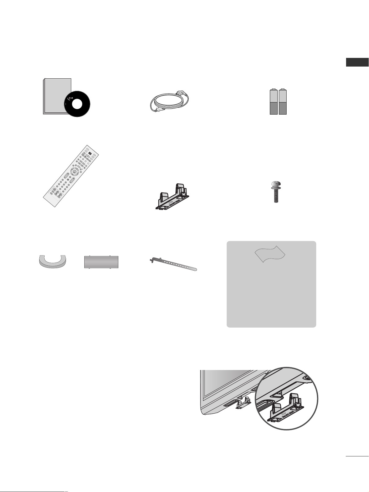
ACCESSORIES
ACCESSORIES
Ensure that the following accessories are included with your TV. If an accessory is missing, please contact the
dealer where you purchased the TV.
Owner's
Manual
Owner's manual
Owner’s Manual
Batteries
OK
INPUT
MODE
TV
D/A
DVD
EX
IT
VOL PR
GUIDE
BA
C
K
MENU
RATIO
I/II
VCR
POWER
123
456
789
0
Q.VIEW
LIST
INDEX
S
LE
E
P
HOLD
R
E
V
E
A
L
?
SUBTITLE
TEXT
INPUT
BRIGHT
MUTE
TV/RADIO
UPDATE
SIMPLINK
INFO i
FAV
TIM
E
Remote Control
Power Cord
Cable management clip
(50PG6**)
Cable Holder
(42PG6**)
Protection Cover
When installing the wall-mounted unit, use the protection
cover for desk-type stand installation.
NOT USING THE DESK-TYPE STAND
4-Bolts for stand assembly
(Refer to p.6)
(Only 42PG6**)
x 4
A
Image shown may differ from your TV.

2
CONTENTS
CONTENTS
ACCESSORIES
. . . . . . . . . . . . . . . . . . . . . . . . . . . . . . . . . . . . . . . . . . . . .
1
PREPARATION
Front Panel Controls . . . . . . . . . . . . . . . . . . . . . . . . 4
Back Panel Information . . . . . . . . . . . . . . . . . . . . . . 5
Stand Installation . . . . . . . . . . . . . . . . . . . . . . . . . . . 6
Please set it up carefully so the product
does not fall over . . . . . . . . . . . . . . . . . . . . . . . . . . . 7
Back Cover for Wire Arrangement . . . . . . . . . . . . . . 8
Desktop Pedestal Installation . . . . . . . . . . . . . . . . . . 9
Wall Mount: Horizontal Installation . . . . . . . . . . . . . 9
Antenna Connection . . . . . . . . . . . . . . . . . . . . . . . . 10
EXTERNAL EQUIPMENT SETUP
HD Receiver Setup . . . . . . . . . . . . . . . . . . . . . . . . 11
DVD Setup . . . . . . . . . . . . . . . . . . . . . . . . . . . . . . . . 13
VCR Setup . . . . . . . . . . . . . . . . . . . . . . . . . . . . . . . . 16
Digital Audio Out Setup . . . . . . . . . . . . . . . . . . . . . 18
Other A/V Source Setup . . . . . . . . . . . . . . . . . . . . 19
PC Setup . . . . . . . . . . . . . . . . . . . . . . . . . . . . . . . . . 20
- Screen Setup for PC mode . . . . . . . . . . . . . . . 23
WATCHING TV / PROGRAMME CONTROL
Remote Control Key Functions . . . . . . . . . . . . . . . . 27
Turning on the TV . . . . . . . . . . . . . . . . . . . . . . . . . . 29
Programme Selection . . . . . . . . . . . . . . . . . . . . . . . 30
Volume Adjustment . . . . . . . . . . . . . . . . . . . . . . . . 30
On-Screen Menus Selection and Adjustment . . . . 31
Auto Programme Tuning (In Digital Mode) . . . . . . 32
Manual Programme Tuning (In Digital Mode) . . . . 33
Programme Edit (In Digital Mode) . . . . . . . . . . . . . 34
5V Antenna Power(In Digital Mode Only) . . . . . . .36
Booster (In Digital Mode Only) . . . . . . . . . . . . . . . 37
Software Update (In Digital Mode Only) . . . . . . . 38
Diagnostics (In Digital Mode Only) . . . . . . . . . . . . 39
Auto Programme Tuning (In Analogue Mode) . . . . . 40
Manual Programme Tuning (In Analogue Mode)
. . . . . . . 41
Fine Tuning (In Analogue Mode) . . . . . . . . . . . . . . 42
Assigning a Station Name (In Analogue Mode)
. . . . . . 42
Programme Edit (In Analogue Mode)
. . . . . . . . . . . . . 43
Selecting the Programme Table . . . . . . . . . . . . . . 45
Input Source Selection . . . . . . . . . . . . . . . . . . . . . 46
SIMPLINK Function . . . . . . . . . . . . . . . . . . . . . . . . 47
EPG (ELECTRONIC PROGRAMME GUIDE)
(IN DIGITAL MODE)
Switch On/Off EPG . . . . . . . . . . . . . . . . . . . . . . . . . 49
Select Programme . . . . . . . . . . . . . . . . . . . . . . . . . . 49
Button Function in NOW/NEXT Guide Mode . . . . . 50
Button Function in 8 Day Guide Mode . . . . . . . . . . 50
Button Function in Date Change Mode . . . . . . . . . . 50
Button Function in Extended Description Box . . . . . 51
Button Function in Remind Mode . . . . . . . . . . . . . . 51
Button Function in Schedule List Mode . . . . . . . . . . 51
PICTURE CONTROL
Picture Size (Aspect Ratio) Control . . . . . . . . . . . . . . . . . 52
Preset Picture Settings
- Picture Mode-Preset . . . . . . . . . . . . . . . . . . . . . . . . . . 54
-
Auto Colour Tone Control (Warm/Medium/Cool)
. . . .55
Manual Picture Adjustment
- Picture Mode-User Option . . . . . . . . . . . . . . . . . . . . 56
- Colour Tone - User Option . . . . . . . . . . . . . . . . . . . . .57
XD - Picture Improvement Technology . . . . . . . . . . . . . . 58
XD Demo . . . . . . . . . . . . . . . . . . . . . . . . . . . . . . . . . . . . . . 59
Advanced - Cinema . . . . . . . . . . . . . . . . . . . . . . . . . . . . . . 60
Advanced - Black(Darkness) Level . . . . . . . . . . . . . . . . . . 61
Picture Reset . . . . . . . . . . . . . . . . . . . . . . . . . . . . . . . . . . . . 62
Image Sticking Minimization(ISM) Method . . . . . . . . . . . 63
Low-Power Picture Mode . . . . . . . . . . . . . . . . . . . . . . . . . . 64

3
CONTENTS
SOUND & LANGUAGE CONTROL
Auto Volume Leveler . . . . . . . . . . . . . . . . . . . . . . . . 65
Preset Sound Settings - Sound Mode . . . . . . . . . . 66
Sound Setting Adjustment - User Mode . . . . . . . . . . 67
Balance . . . . . . . . . . . . . . . . . . . . . . . . . . . . . . . . . . . 68
TV Speakers On/Off Setup . . . . . . . . . . . . . . . . . . 69
Selecting Digital Audio . . . . . . . . . . . . . . . . . . . . . . 70
I/II
-
Stereo/Dual Reception (In Analogue Mode Only)
. 71
-
NICAM Reception (In Analogue Mode Only) . . . . . . .
72
- Speaker Sound Output Selection . . . . . . . . . . 72
Language Selection
(In Digital Mode Only) . . . . . .73
TIME SETTING
Clock Setup . . . . . . . . . . . . . . . . . . . . . . . . . . . . . 74
Auto On/Off Timer Setting . . . . . . . . . . . . . . . . . 75
Auto Shut-Off Setting . . . . . . . . . . . . . . . . . . . . . 76
Time Zone Setup . . . . . . . . . . . . . . . . . . . . . . . . . 77
Sleep Timer Setting . . . . . . . . . . . . . . . . . . . . . . . 77
PARENTAL CONTROL / RATINGS
Set Password & Lock System . . . . . . . . . . . . . . . . . 78
Parental Control . . . . . . . . . . . . . . . . . . . . . . . . . . . 79
TELETEXT
Switch On/Off . . . . . . . . . . . . . . . . . . . . . . . . . . . . . 80
SIMPLE Text . . . . . . . . . . . . . . . . . . . . . . . . . . . . . . . 80
TOP Text . . . . . . . . . . . . . . . . . . . . . . . . . . . . . . . . . 80
FASTEXT . . . . . . . . . . . . . . . . . . . . . . . . . . . . . . . . . 81
Special Teletext Functions . . . . . . . . . . . . . . . . . . . . 81
APPENDIX
Troubleshooting . . . . . . . . . . . . . . . . . . . . . . . . . . 82
Maintenance . . . . . . . . . . . . . . . . . . . . . . . . . . . . 84
Product Specifications . . . . . . . . . . . . . . . . . . . . . 85
Programming the Remote Control . . . . . . . . . . . . 86
Programming Code . . . . . . . . . . . . . . . . . . . . . . . 86
IR Codes . . . . . . . . . . . . . . . . . . . . . . . . . . . . . . . 88
External Control Device Setup . . . . . . . . . . . . . . 90
4
PREPARATION
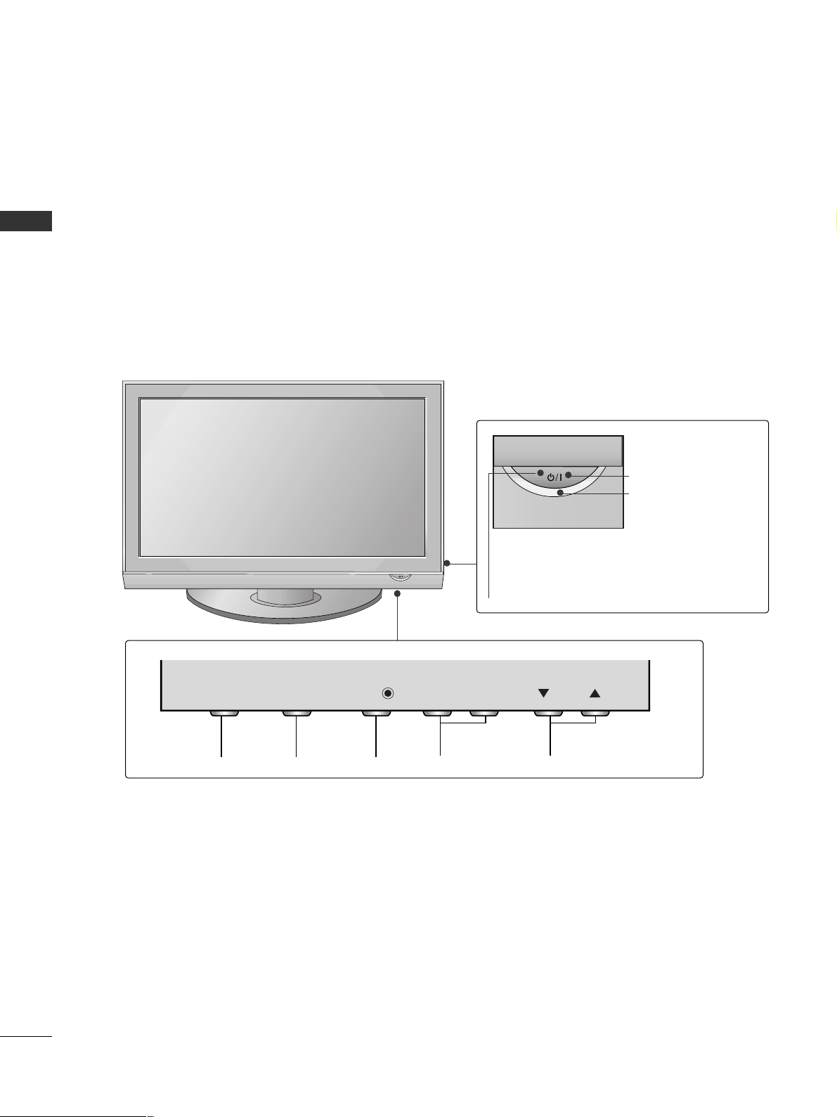
FRONT PANEL CONTROLS
PREPARATION
A
Image shown may differ from your TV.
A
If your TV has a protection film attached, remove the film and then wipe the TV with a polishing cloth.
PROGRAMMEVOLUMEMENU OKINPUT
Remote Control Sensor
POWER
Power/Standby Indicator
• illuminates red in standby mode.
• illuminates green when the TV is
switched on.
VOL
OK
MENU
INPUT
INPUT
MENU
OK
- +
VOL
PR
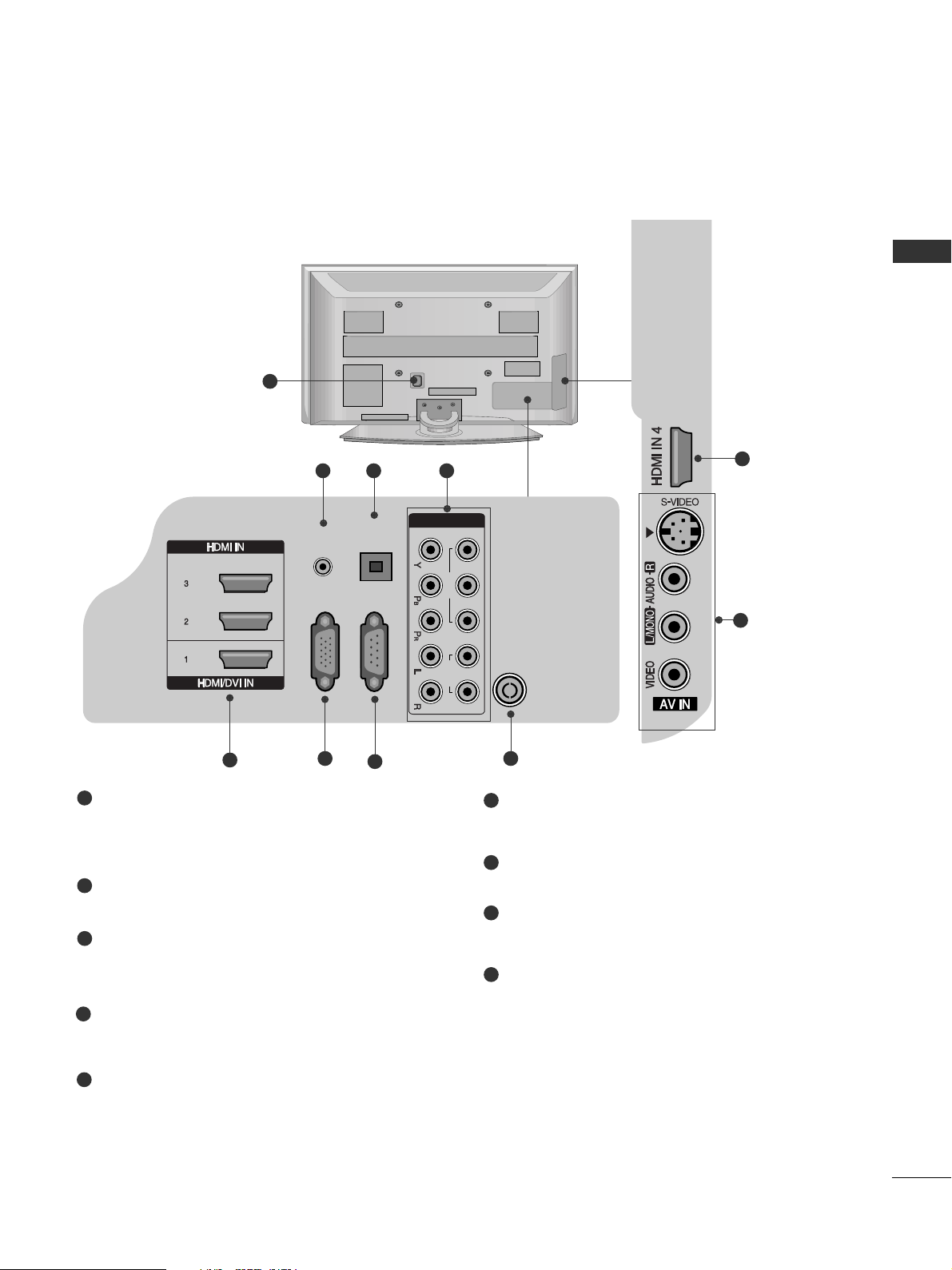
Power Cord Socket
This TV operates on an AC power. The voltage is
indicated on the Specifications page. Never
attempt to operate the TV on DC power.
AUDIO IN (RGB/DVI)
Connect the audio from a PC.
OPTICAL DIGITAL AUDIO OUT
Connect digital audio from various types of equipment.
Note: In standby mode, these ports do not work.
Component Input
Connect a component video/audio device to
these jacks.
HDMI IN 1/2/3/4
Connect a HDMI signal to HDMI IN or DVI (VIDEO)
signal to HDMI/DVI port with DVI to HDMI cable.
RGB IN (PC)
Connect the output from a PC.
RS-232C IN (CONTROL & SERVICE) PORT
Connect to the RS-232C port on a PC.
Antenna Input
Connect RF antenna to this jack.
AV (Audio/Video) IN
Connect audio/video output from an external
device to these jacks.
S-VIDEO
Connect S-Video out from an S-VIDEO device.
5
BACK PANEL INFORMATION
A
Image shown may differ from your TV.
1
2
3
4
5
7
6
8
9
1
5
2 43
8
7
6
5
PREPARATION
9
OPTICAL
DIGITAL
AUDIO OUT
(CONTROL & SERVICE)
AUDIO IN
(RGB/DVI)
RGB IN
(PC)
COMPONENT IN
1 2
VIDEO
RS-232C IN
AUDIO
ANTENNA IN
6
PREPARATION
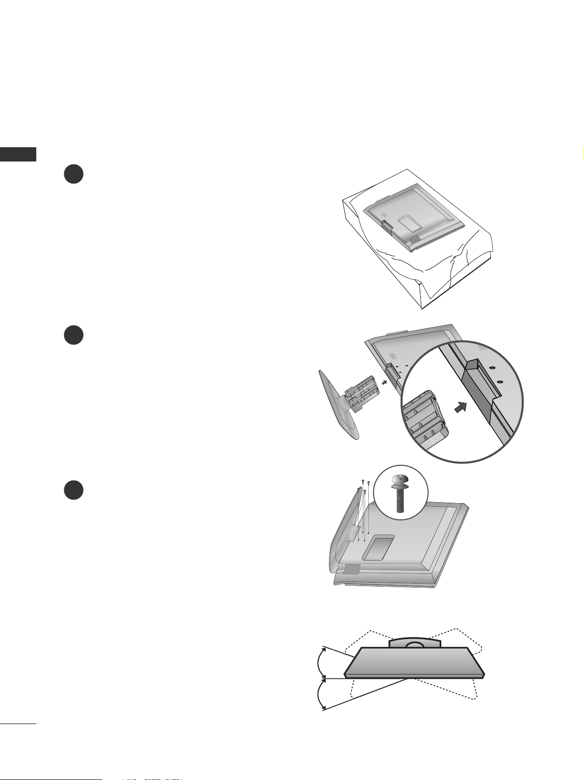
STAND INSTALLATION
(only 42PG6**)
1
2
3
Carefully place the TV screen side down on a
cushioned surface to protect the screen from
damage.
Assemble the TV as shown.
Fix the 4 bolts securely using the holes in the
back of the TV.
Swivel Stand
After installing the TV, you can adjust the TV set
manually to the left or right direction by 20 degrees
to suit your viewing position.
PREPARATION
A
When assembling the desk type stand, check whether the bolt is fully tightened. (If not tightened fully, the
product can tilt forward after the product installation.) If you tighten the bolt with excessive force, the bolt
can deviate from abrasion of the tightening part of the bolt.
7
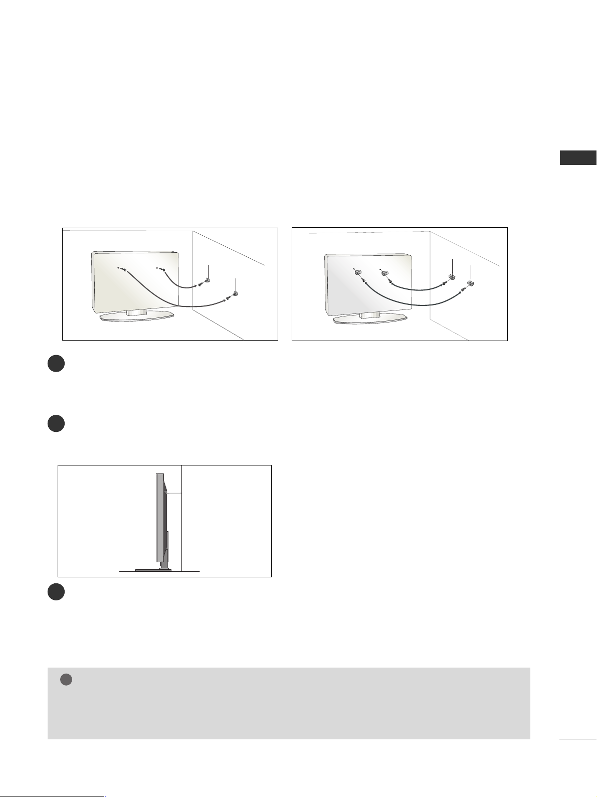
PLEASE SET IT UP CAREFULLY SO THE PRODUCT DOES NOT FALL OVER.
■
You should purchase necessary components to fix the TV to the wall on the market.
■
Position the TV close to the wall to avoid the possibility of it falling when pushed.
■
The instructions shown below are a safer way to set up the TV, which is to fix it to the wall, avoiding the possibility of it falling forwards if pulled. This will prevent the TV from falling forward and causing injury. This will
also prevent the TV from damage. Ensure that children do not climb or hang from the TV.
NOTE
!
G
When moving the TV undo the cords first.
G
Use a platform or cabinet strong and large enough to support the size and weight of the TV.
G
To use the TV safely make sure that the height of the bracket on the wall and on the TV is the same.
3
1
2
Use the eye-bolts or TV brackets/bolts to fix the TV to the wall as shown in the picture.
(If your TV has bolts in the eyebolts, loosen these bolts.)
* Insert the eye-bolts or TV brackets/bolts and tighten them securely in the upper holes.
Secure the wall brackets with the bolts on the wall. Match the height of the bracket that is mounted
on the wall.
3
Use a sturdy rope to tie the TV. It is safer to tie the rope so it becomes horizontal between the wall
and the TV.
2
1
2
1
PREPARATION
8
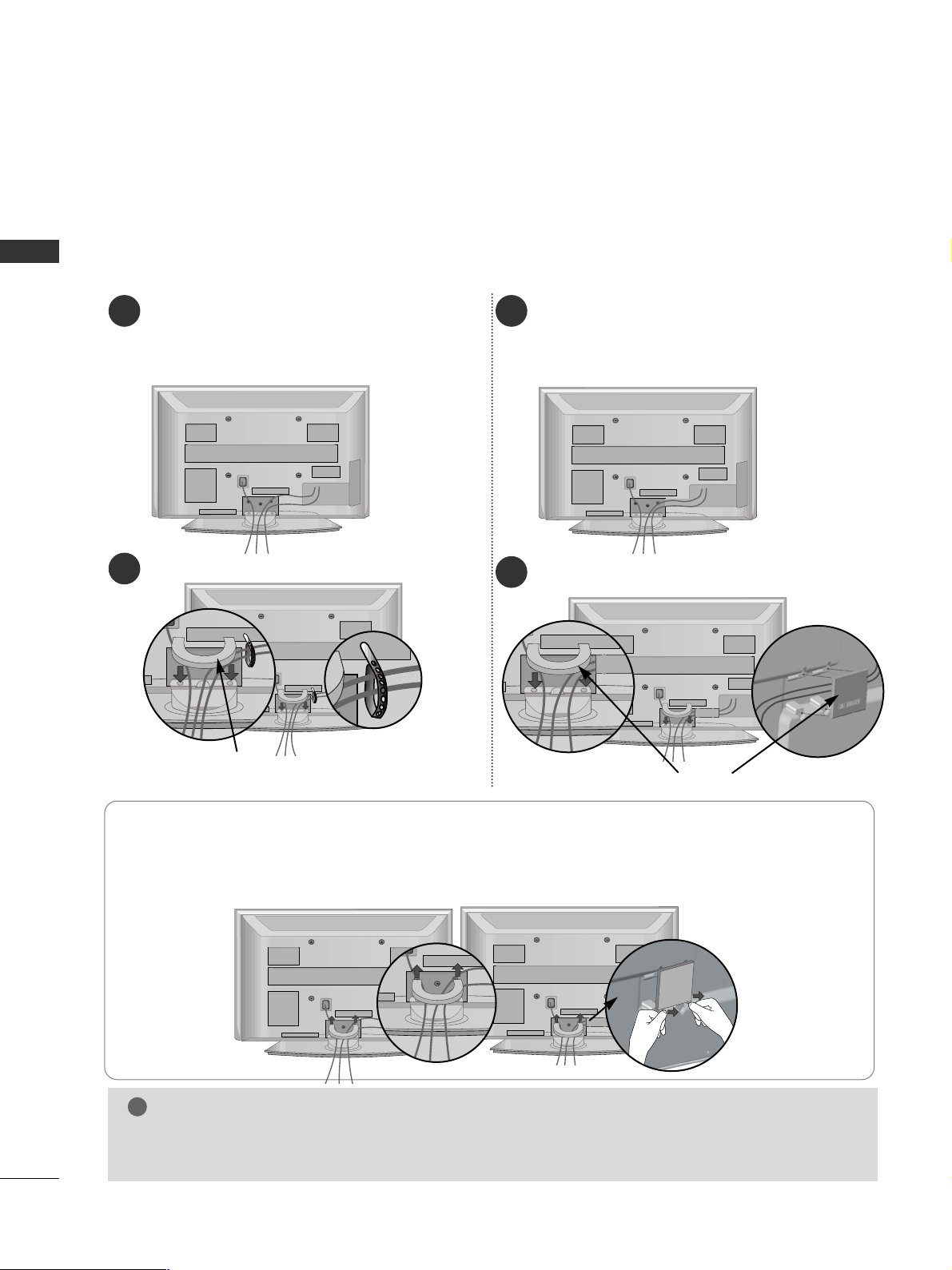
PREPARATION
BACK COVER FOR WIRE ARRANGEMENT
Connect the cables as necessary.
To connect additional equipment, see the
EExx tteerrnnaa ll ee qquuii ppmmeenntt SSeettuupp
section.
1
Install the
CCAABBLLEE MMAANNAAGGEEMMEENNTT CCLLIIPP
as shown.
2
Hold the
CC AABBLLEE MMAANNAA GGEEMMEENNTT CCLLIIPP
with both hands and pull it upward.
NOTE
!
GG
Do not use the CABLE MANAGEMENT CLIP to lift the TV.
- If the TV is dropped, you may be injured or the TV may be damaged.
HHooww ttoo rreemmoovvee tthhee ccaabbllee mmaannaaggeemmeenntt cclliipp
■
Image shown may differ from your TV.
CABLE MANAGEMENT CLIP
Connect the cables as necessary.
To connect additional equipment, see the
EExx tteerrnnaa ll ee qquuiippmmeenntt SSee ttuupp
section.
1
Install the
CC AABBLLEE MMAA NNAAGGEEMMEENN TT CCLLIIPP
as shown.
2
CABLE MANAGEMENT CLIP
42PG6
**
50PG6
**
50PG6
**
42PG6
**
Separate CABLE
MANAGEMENT from
TV by pressing two
latches.
Fix the
CC aabb llee HHoollddeerr
as
shown and bundle the
cables.
For the 42PG6**
model, press the
center of the
CABLE MANAGEMENT CLIP and
then lift up it.
PREPARATION
9
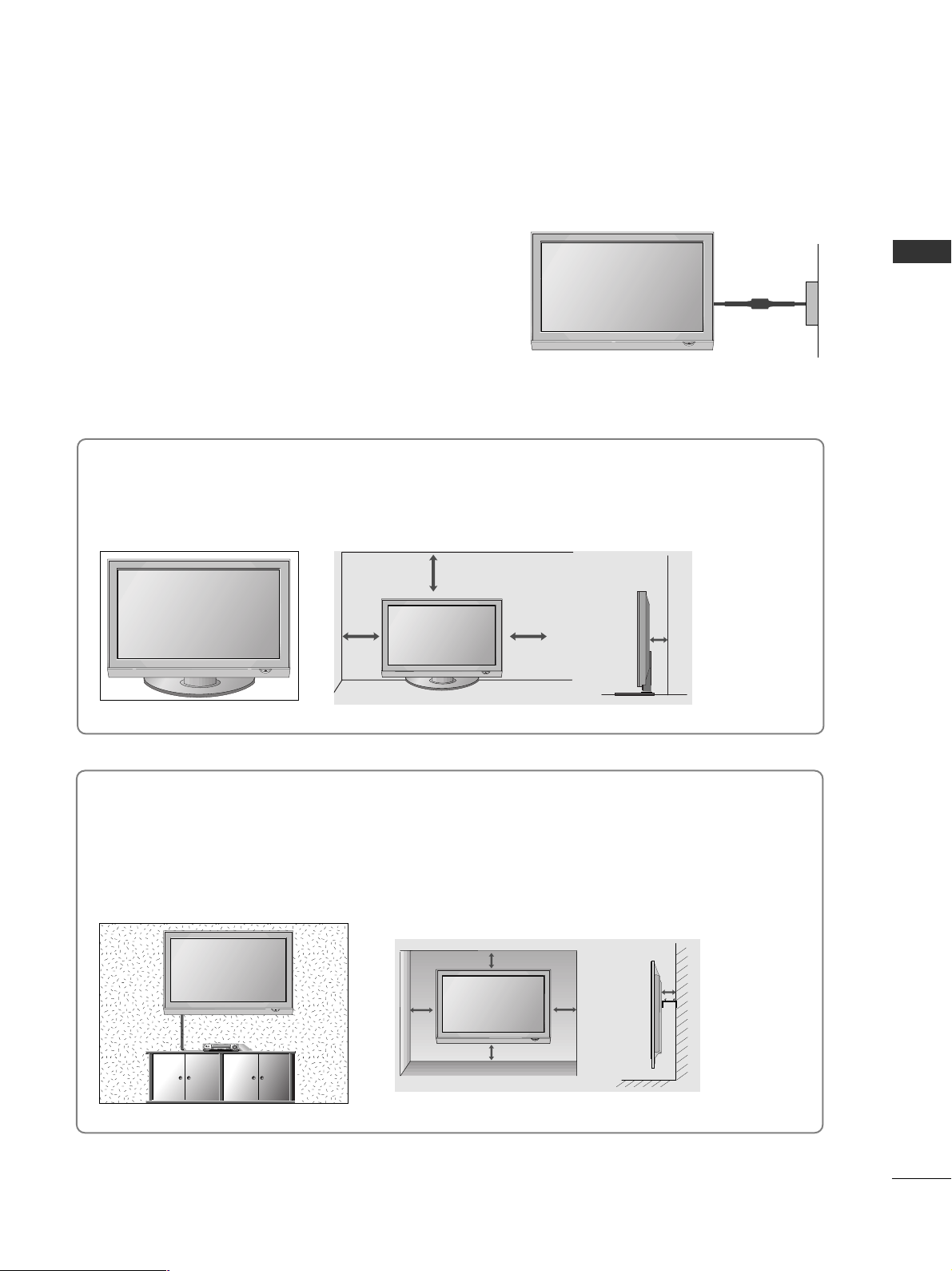
DESKTOP PEDESTAL INSTALLATION
For adequate ventilation allow a clearance of 4” (10cm) all around the TV.
EARTHING
Ensure that you connect the earth wire to prevent possible
electric shock. Do not try to earth the TV by connecting it
to telephone wires, lightening rods or gas pipes.
Power Supply
Circuit
breaker
■
The TV can be installed in various ways such as on a wall or on a desktop etc.
■
The TV is designed to be mounted horizontally.
4 inches
4 inches 4 inches 4 inches
WALL MOUNT: HORIZONTAL INSTALLATION
For adequate ventilation allow a clearance of 4” (10cm) all around the TV. We recommend that you use
a wall mounting bracket of LG brand when mounting the TV to a wall.
4 inches
4 inches
4 inches 4 inches
4 inches
PREPARATION
ANTENNA IN
10
PREPARATION
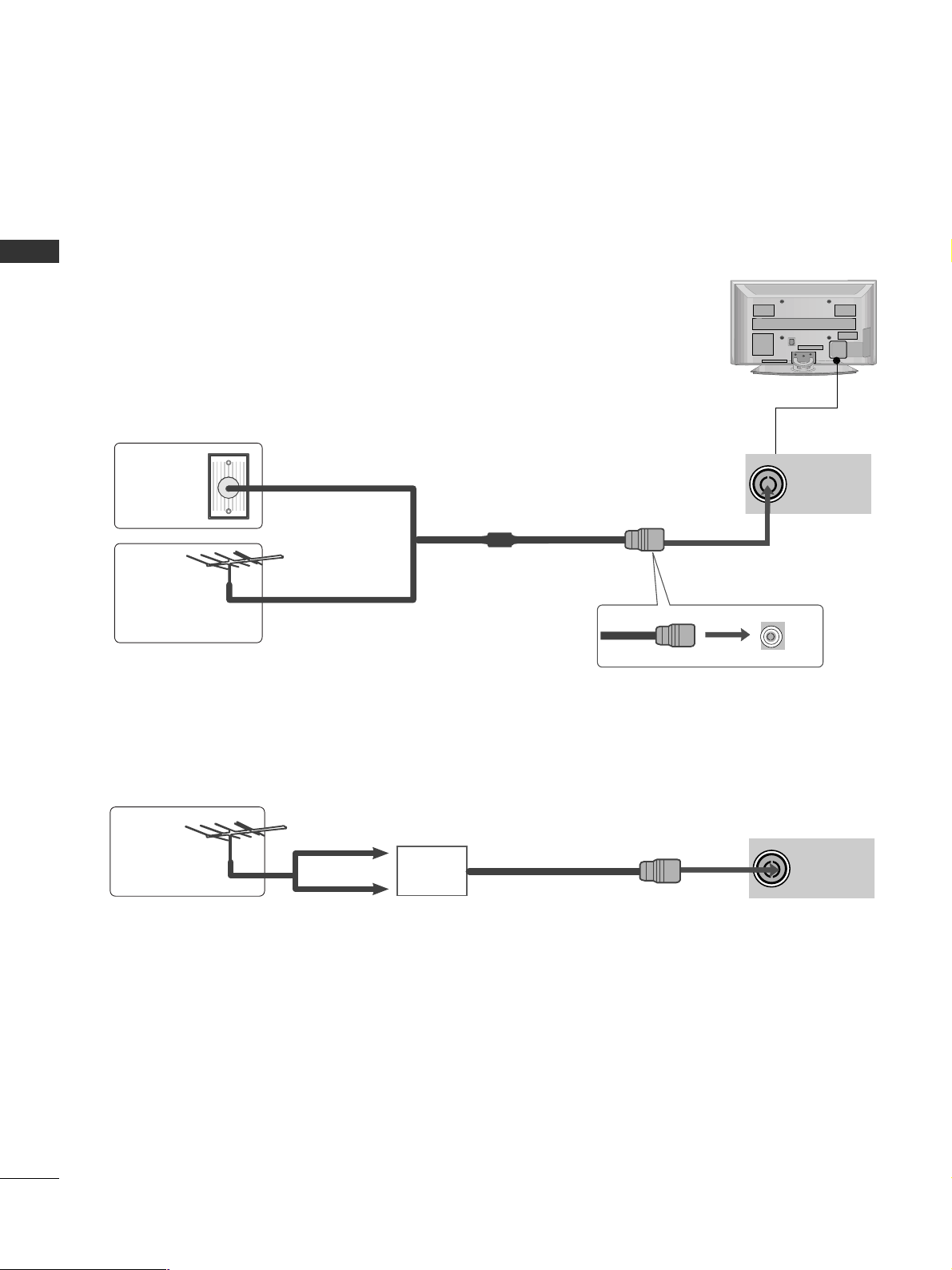
ANTENNA IN
■
For optimum picture quality, adjust antenna direction.
■
An antenna cable and converter are not supplied.
■
To prevent damage do not connect to the mains outlet until all connections are made between the devices.
Multi-family Dwellings/Apartments
(Connect to wall antenna socket)
Single-family Dwellings /Houses
(Connect to wall jack for outdoor antenna)
Outdoor
Antenna
(VHF, UHF)
Wall
Antenna
Socket
RF Coaxial Wire (75 ohm)
ANTENNA CONNECTION
Antenna
UHF
Signal
Amplifier
VHF
■
In poor signal areas, to achieve better picture quality it may be necessary to install a signal amplifier to the
antenna as shown above.
■
If signal needs to be split for two TVs,use an antenna signal splitter for connection.
- 5V antenna power works In Digital
mode only. (Refer to p. 36)
PREPARATION
11
EXTERNAL EQUIPMENT SETUP
HD RECEIVER SETUP
■
This TV can receive Digital RF/Cable signals without an external digital set-top box. However, if you do receive
Digital signals from a digital set-top box or other digital external device, refer to the diagram as shown below.
VIDEO
12
AUDIO
COMPONENT IN
RGB IN
(PC)
RS-232C IN
(CONTROL & SERVICE)
OPTICAL
DIGITAL
AUDIO OUT
AUDIO IN
(RGB/DVI)
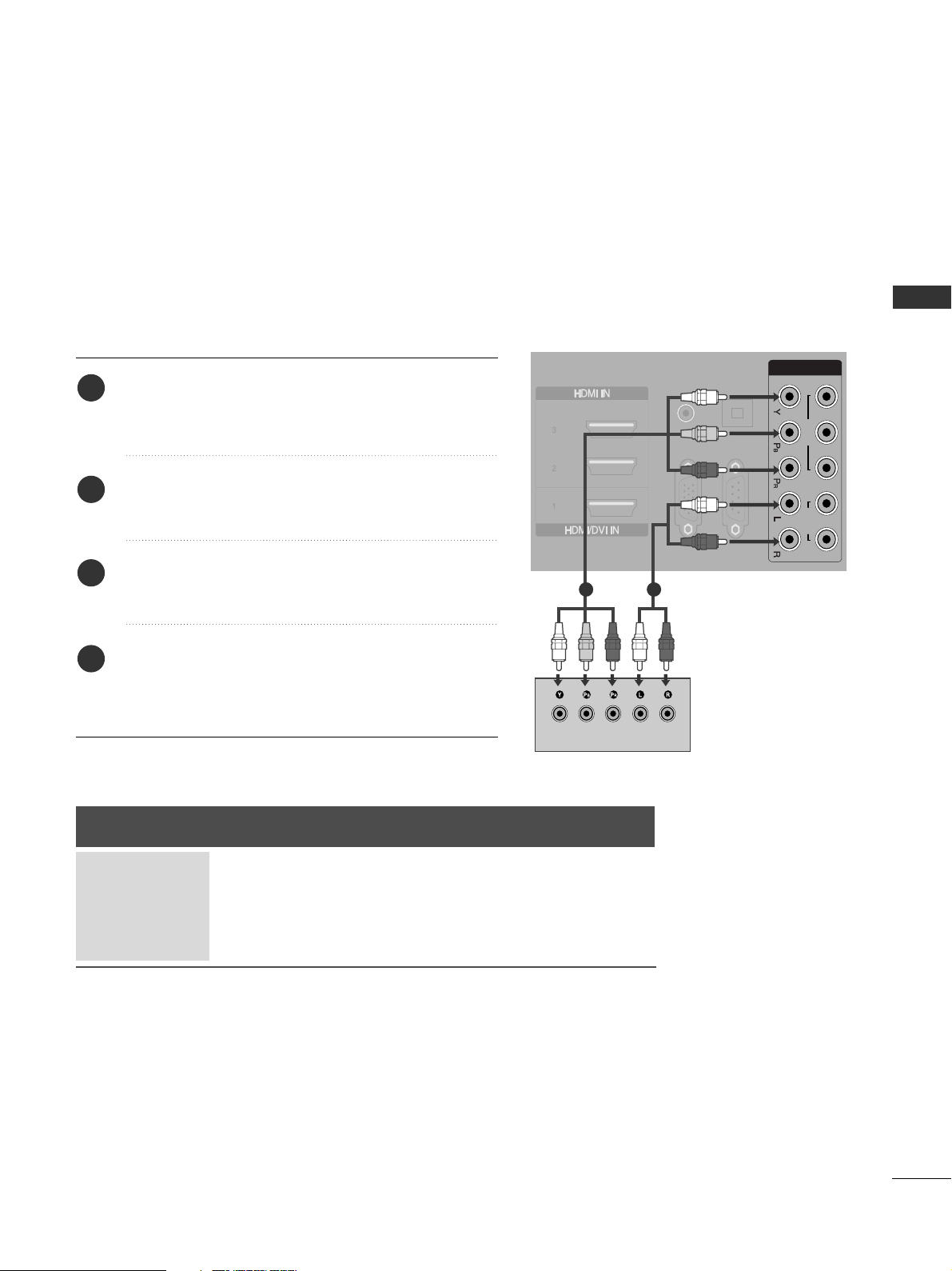
Connecting with a component cable
Connect the video outputs (Y, PB
, PR
)
of the digital set
top box to the
CC OOMMPPOO NNEENNTT IINN11 VVIIDDEEOO
jacks on
the TV.
Connect the audio output of the digital set-top box to
the
CC OOMMPPOO NNEENNTT II NN11 AAUU DDIIOO
jacks on the TV.
Turn on the digital set-top box.
(
Refer to the owner’s manual for the digital set-top box.
)
Select Component1 input source using the
II NNPPUU TT
button on the remote control.
If connected to
CC OOMMPPOO NNEENNTT II NN22
, select
Component2 input source.
2
3
4
1
Signal
480i/576i
480p/576p
720p/1080i
10 8 0 p
Component
Yes
Yes
Yes
No
HDMI1/2/3/4
No
Yes
Yes
Yes
1 2
■
To avoid damaging any equipment, never plug in any power cords until you have finished connecting all equipment.
EXTERNAL EQUIPMENT SETUP
12
EXTERNAL EQUIPMENT SETUP
RGB IN
(PC)
RS-232C IN
(CONTROL & SERVICE)
DIGITAL
AUDIO OUT
(RGB/DVI)
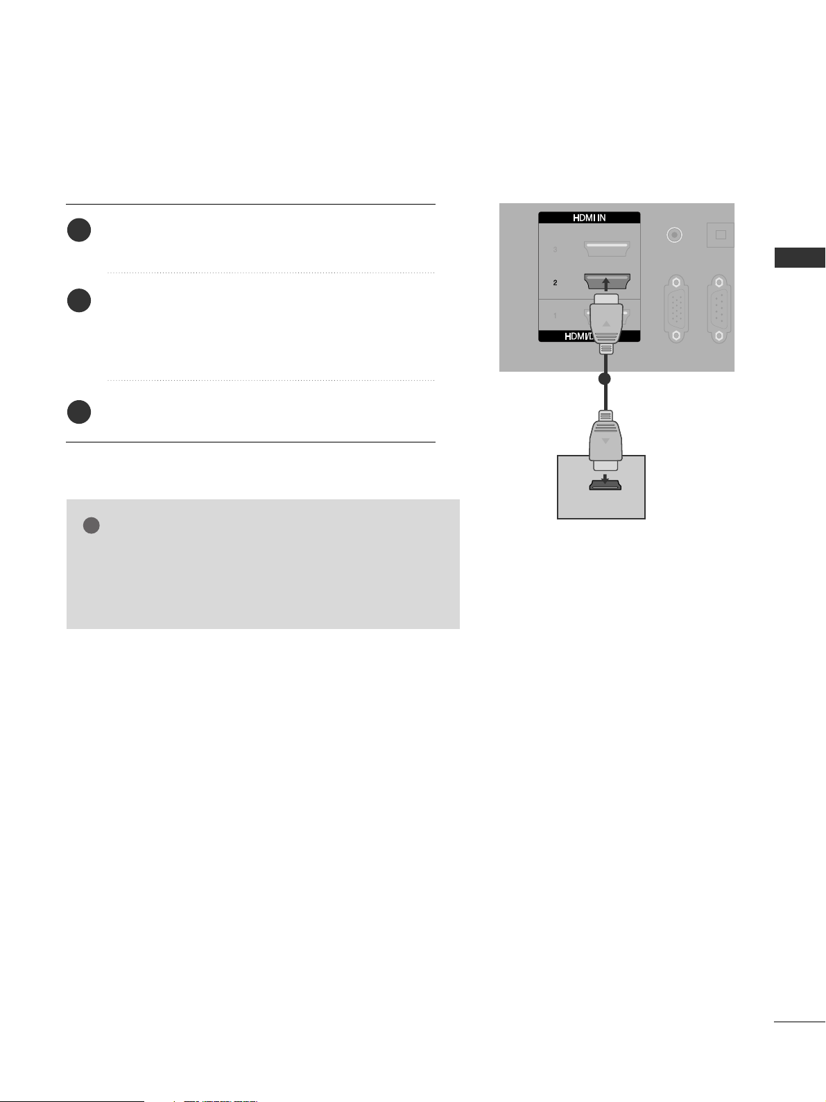
HDMI-DTV OUTPUT
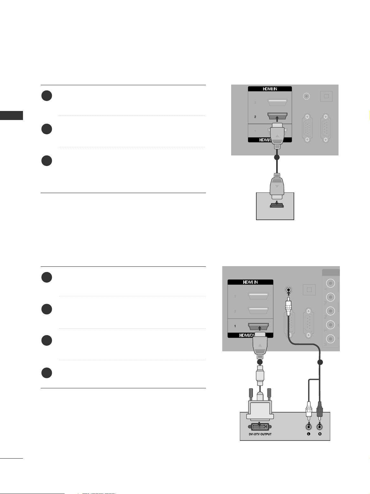
Connecting a set-top box with an HDMI cable
Connect the digital set-top box to
HHDDMMII IINN 22
jack on
the TV.
Turn on the digital set-top box.
(
Refer to the owner’s manual for the digital set-top box.
)
Select HDMI2 input source using the
II NNPPUU TT
button
on the remote control.
If connected to
HHDDMMII II NN 33
(or
HHDDMMII II NN 44
) jack,
select HDMI3 (or HDMI4) input source.
2
3
1
AUDIO IN
(RGB/DVI)
VIDEO AUDIO
COMPONE
RGB IN
(PC)
RS-232C IN
(CONTROL & SERVICE)
OPTICAL
DIGITAL
AUDIO OUT
1
1
2
Connect the digital set-top box to
HHDDMMII//DDVVII II NN 11
jack on the TV.
Connect the audio output of the digital set-top box to
the
AAUU DDIIOO II NN ((RRGGBB// DDVVII))
jack on the TV.
Turn on the digital set-top box. (Refer to the owner’s
manual for the digital set-top box.
)
Select HDMI1 input source using the
II NNPPUU TT
button
on the remote control.
2
3
4
1
Connecting with a HDMI to DVI cable
EXTERNAL EQUIPMENT SETUP
13
DVD SETUP
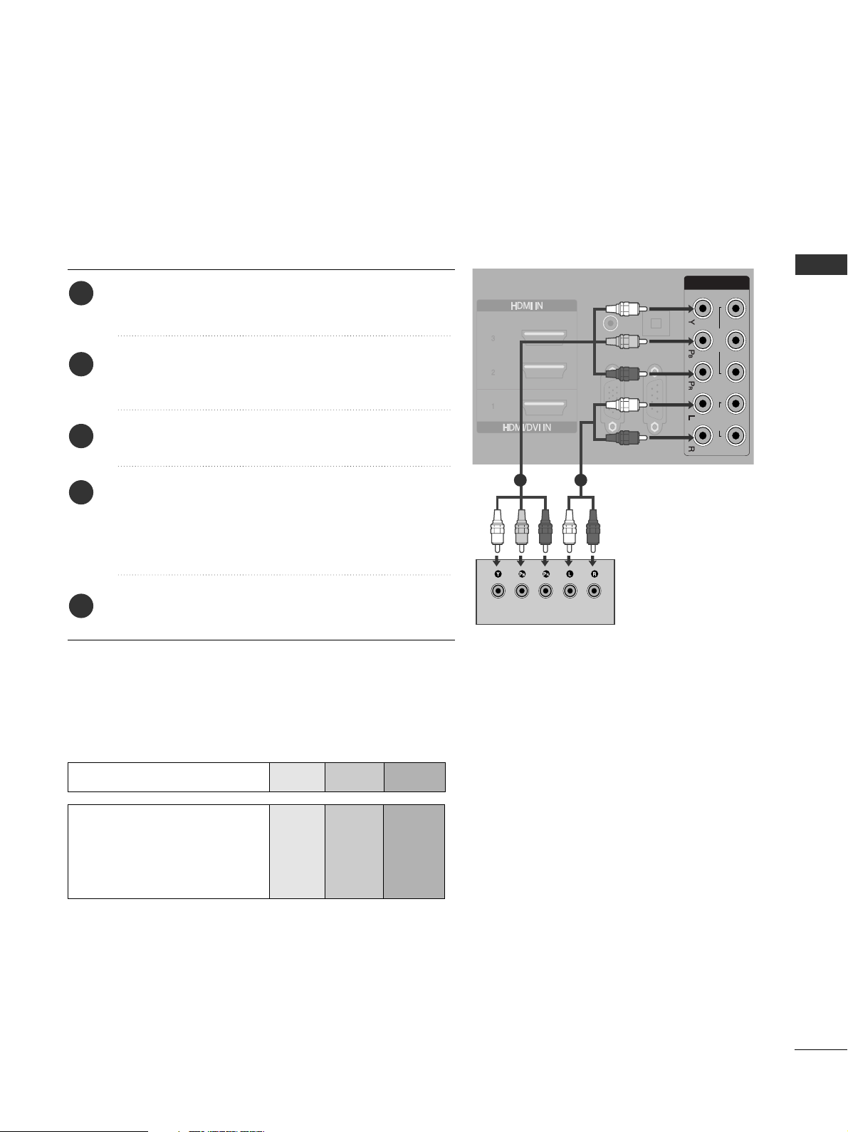
Connecting with a component cable
Component Input ports
To achieve better picture quality, connect a DVD player to the component input ports as shown below.
Component ports on the TV
YPB PR
Video output ports
on DVD player
Y
Y
Y
Y
P
B
B-Y
Cb
Pb
P
R
R-Y
Cr
Pr
Connect the video outputs (Y, PB, PR
)
of the DVD to the
CC OOMMPPOO NNEENNTT II NN11 VVIIDD EEOO
jacks on the TV.
Connect the audio outputs of the DVD to the
CC OOMMPPOO NNEENNTT II NN11 AAUU DDIIOO
jacks on the TV.
Turn on the DVD player, insert a DVD.
Select Component1 input source using the
II NNPPUU TT
button on the remote control.
If connected to
CC OOMMPPOO NNEENNTT II NN22
, select
Component2 input source.
Refer to the DVD player's manual for operating
instructions.
2
3
4
5
1
VIDEO
12
AUDIO
COMPONENT IN
RGB IN
(PC)
RS-232C IN
(CONTROL & SERVICE)
OPTICAL
DIGITAL
AUDIO OUT
AUDIO IN
(RGB/DVI)
1 2
EXTERNAL EQUIPMENT SETUP

14
EXTERNAL EQUIPMENT SETUP
Connecting with a S-Video cable
L R
S-VIDEOVIDEO
OUTPUT
SWITCH
ANT IN
ANT OUT
Connect the S-VIDEO output of the DVD to the
SS--
VVIIDDEEOO
input on the TV.
Connect the audio outputs of the DVD to the
AAUU DDIIOO
input jacks on the TV.
Turn on the DVD player, insert a DVD.
Select AV input source using the INPUT button on
the remote control.
Refer to the DVD player's manual for operating
instructions.
2
3
4
5
1
1
2
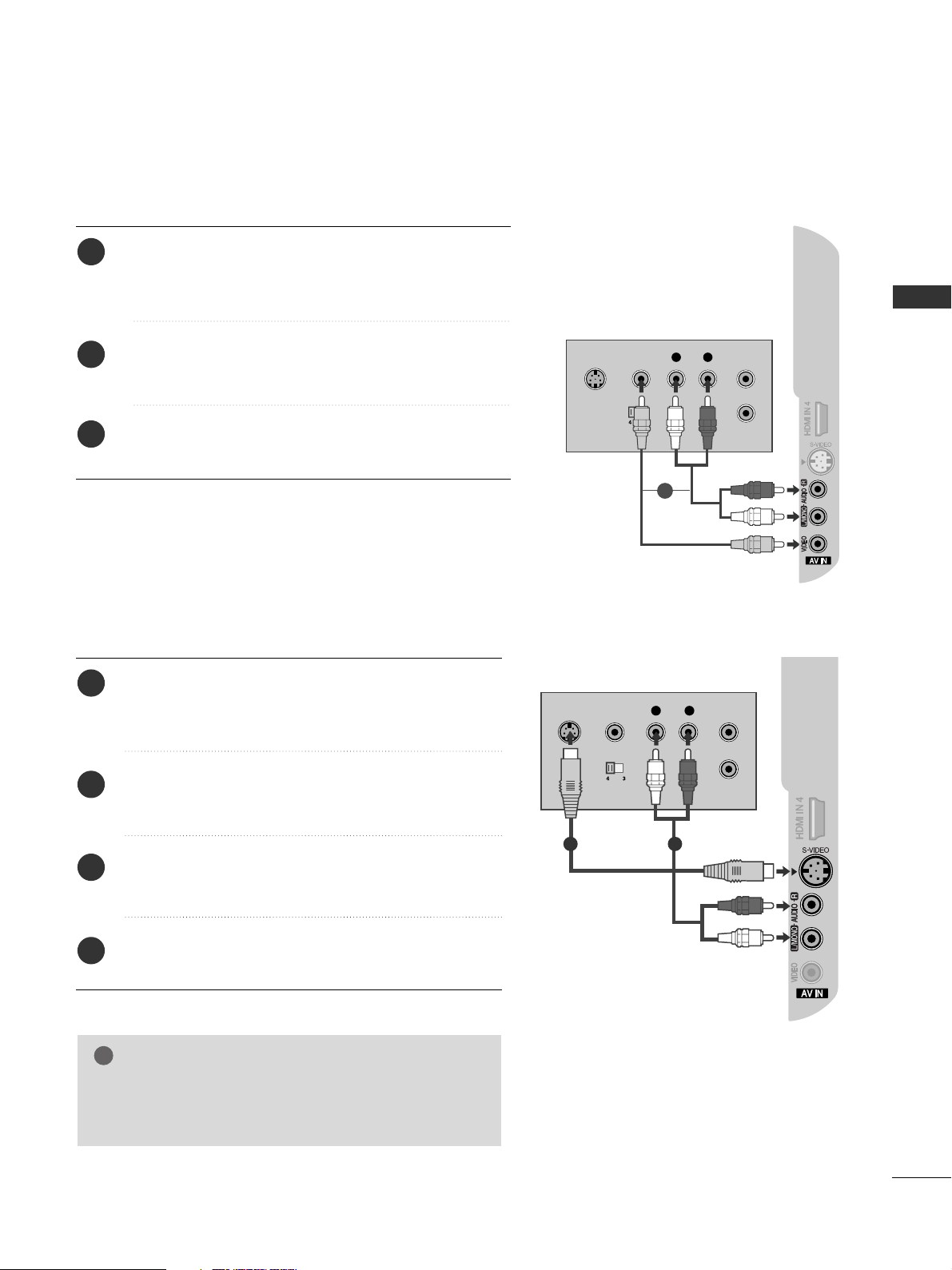
Connecting with a RCA cable
Connect the
AAUU DDIIOO/VVIIDDEEOO
jacks between TV and
DVD player. Match the jack colours (Video = yellow, Audio
Left = white, and Audio Right = red)
Insert a DVD into the DVD player and press PLAY on the
DVD player. (Refer to the DVD player owner’s manual.
)
Select
AV input source using the
II NNPPUU TT
button on the
remote control.
2
3
1
L R
S-VIDEO VIDEO
OUTPUT
SWITCH
ANT IN
ANT OUT
EXTERNAL EQUIPMENT SETUP
1
15
AUDIO IN
(RGB/DVI)
RGB IN
(PC)
(CONTROL & SERVICE)
DIGITAL
AUDIO OUT
HDMI-DVD OUTPUT
Connecting HDMI cable
Connect the HDMI output of the DVD to the
HHDDMMII
II NN 22
jack on the set.
Select HDMI2 input source using the
II NNPPUU TT
button
on the remote control.
If connected to
HHDDMMII II NN 33
(or
HHDDMMII II NN 44
) jack,
select HDMI3 (or HDMI4) input source.
Refer to the DVD player's manual for operating
instructions.
1
2
3
GG
The TV can receive video and audio signals simultaneously
when using a HDMI cable.
GG
If the DVD does not support Auto HDMI, you must set the
output resolution appropriately.
NOTE
!
1
EXTERNAL EQUIPMENT SETUP
16
EXTERNAL EQUIPMENT SETUP
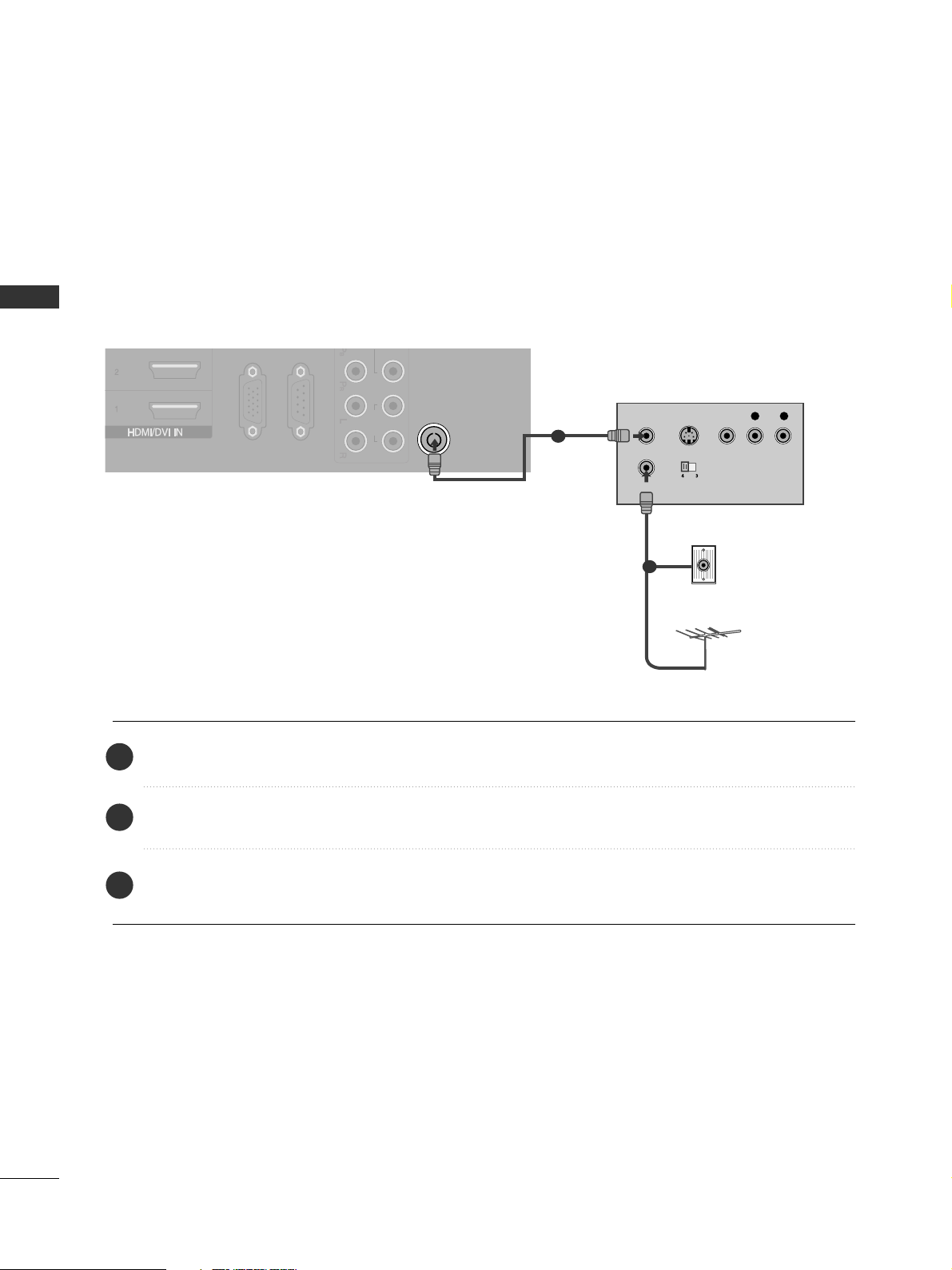
When connecting with a RF Cable
■
To avoid picture noise (interference), allow adequate distance between the VCR and TV.
■
If 4:3 picture format is used for an extended period the fixed images on the sides of the screen may remain
visible.
ANTENNA IN
AUDIO
RGB IN
(PC)
RS-232C IN
(CONTROL & SERVICE)
OUTPUT
SWITCH
ANT IN
R
S-VIDEO VIDEO
ANT OUT
L
Wall Jack
Antenna
Connect the
AANN TT OOUU TT
socket of the VCR to the
AANNTTEENN NNAA II NN
socket on the TV.
Connect the antenna cable to the
AANN TT IINN
socket of the VCR.
Press the PLAY button on the VCR and match the appropriate channel between the TV and VCR for
viewing.
VCR SETUP
1
2
2
3
1
EXTERNAL EQUIPMENT SETUP
17
L R
S-VIDEO VIDEO
OUTPUT
SWITCH
ANT IN
ANT OUT
Connecting with a RCA cable
Connect the
AAUU DDIIOO/VVIIDDEEOO
jacks between TV and
VCR. Match the jack colours (Video = yellow, Audio Left =
white, and Audio Right = red)
Insert a video tape into the VCR and press PLAY on the
VCR. (Refer to the VCR owner’s manual.
)
Select
AV input source using the
II NNPPUU TT
button on the
remote control.
2
3
1
GG
If both S-VIDEO and VIDEO sockets have been
connected to the S-VHS VCR simultaneously, only
the S-VIDEO can be received.
NOTE
!
S-VIDEO
L R
VIDEO
OUTPUT
SWITCH
ANT IN
ANT OUT
Connecting with a S-Video cable
Connect the S-VIDEO output of the VCR to the
SS --
VVIIDDEEOO
input on the TV. The picture quality is improved;
compared to normal composite (RCA cable) input.
Connect the audio outputs of the VCR to the
AAUU DDIIOO
input jacks on the TV.
Insert a video tape into the VCR and press PLAY on the
VCR. (Refer to the VCR owner’s manual.)
Select AV input source using the
IINNPPUUTT
button on the
remote control.
2
3
4
1
1 2
EXTERNAL EQUIPMENT SETUP
1
18
EXTERNAL EQUIPMENT SETUP
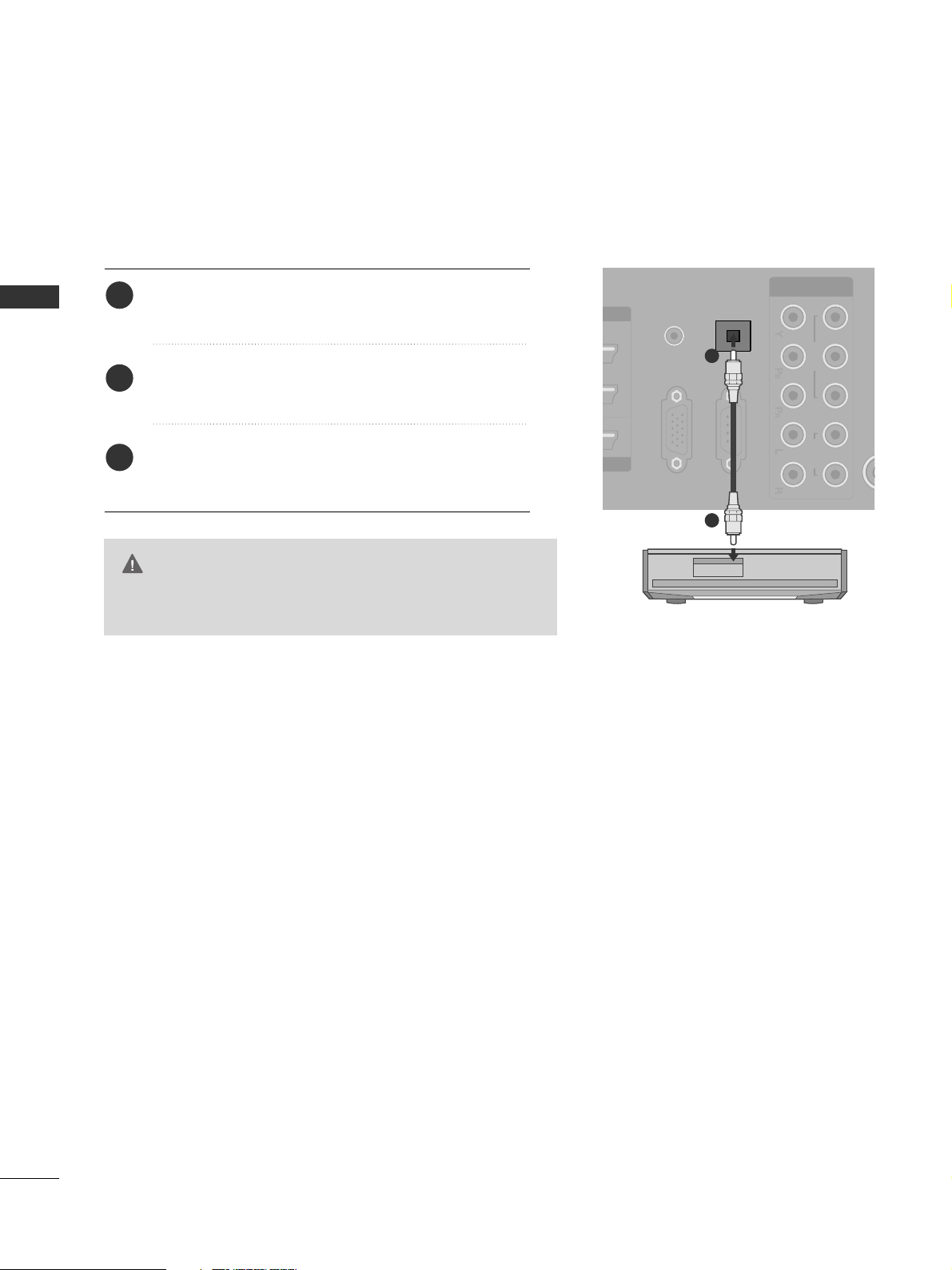
DIGITAL AUDIO OUT SETUP
- Sending the TV’s audio signal to external audio equipment via
the Digital Audio Output (Optical) port.
G
Do not look into the optical output port. Looking at the
laser beam may damage your vision.
CAUTION
OPTICAL
DIGITAL
AUDIO OUT
VIDEO AUDIO
COMPONENT IN
RGB IN
(PC)
RS-232C IN
(CONTROL & SERVICE)
AUDIO IN
(RGB/DVI)
Connect one end of an optical cable to the TV Digital
Audio (Optical)Output port.
Connect the other end of the optical cable to the
digital audio (optical)input on the audio equipment.
Set the “TV Speaker option - Off ” in the AUDIO
menu.(
G
pp..6699
). Refer to the external audio equipment
instruction manual for operation.
2
3
1
1
2
EXTERNAL EQUIPMENT SETUP
19
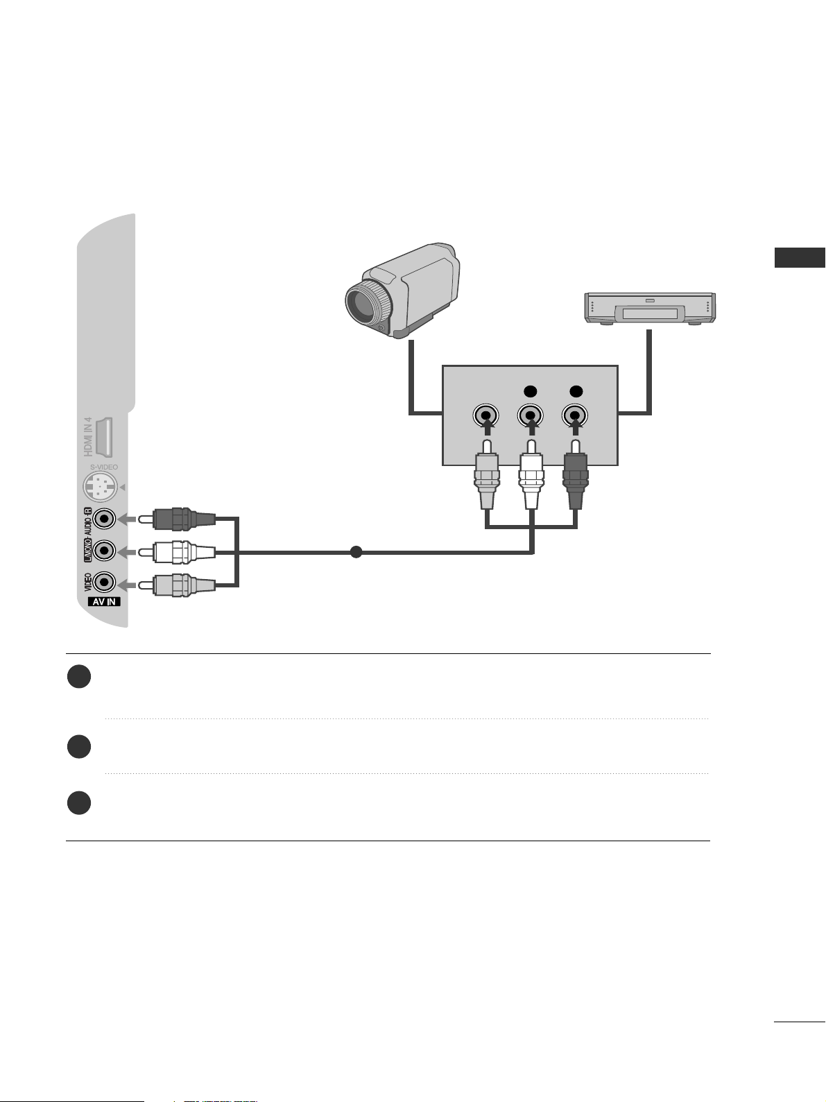
OTHER A/V SOURCE SETUP
Connect the
AAUU DDIIOO/VVIIDDEEOO
jacks between TV and external equipment. Match the jack colors
.
(
Video = yellow, Audio Left = white, and Audio Right = red
)
Select AV input source using the
II NNPPUU TT
button on the remote control.
Operate the corresponding external equipment.
Refer to external equipment operating guide.
L R
VIDEO
Camcorder
Video Game Set
1
1
2
3
EXTERNAL EQUIPMENT SETUP
20
EXTERNAL EQUIPMENT SETUP
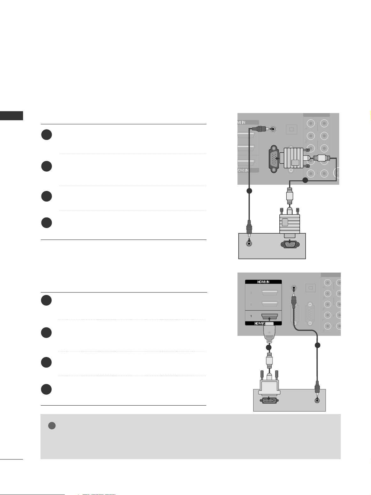
PC SETUP
This TV provides Plug and Play capability, meaning that the PC adjusts automatically to the TV's settings.
Connecting with a D-sub 15 pin cable
RGB IN
(PC)
AUDIO IN
(RGB/DVI)
VIDEO AUDIO
COMPONENT IN
RS-232C IN
(CONTROL & SERVICE)
OPTICAL
DIGITAL
AUDIO OUT
RGB OUTPUT
AUDIO
Connect the RGB output of the PC to the RGB IN
(PC) jack on the TV.
Connect the PC audio output to the AUDIO IN
(RGB/DVI) jack on the TV.
Turn on the PC and the TV.
Select RGB input source using the INPUT button on
the remote control.
2
3
4
1
Connecting with a HDMI to DVI cable
GG
If the PC has a DVI output and no HDMI output, a separated audio connection is necessary.
GG
If the PC does not support Auto DVI, you need to set the output resolution appropriately.
NOTE
!
AUDIO IN
(RGB/DVI)
VIDEO AUDIO
COMPONENT IN
RGB IN
(PC)
RS-232C IN
(CONTROL & SERVICE)
OPTICAL
DIGITAL
AUDIO OUT
AUDIO
DVI-PC OUTPUT
Connect the DVI output of the PC to the
HHDDMMII//DDVVII
II NN 11
jack on the TV.
Connect the PC audio output to the
AAUU DDIIOO IINN
((RR GGBB //DD VVII))
jack on the TV.
Turn on the PC and the TV.
Select HDMI1 input source using the INPUT button
on the remote control.
2
3
4
1
2
1
1
2
EXTERNAL EQUIPMENT SETUP

21
NOTE
!
G
To enjoy vivid picture and sound, connect a PC to
the TV.
G
Avoid keeping a fixed image on the TV’s screen for
prolonged periods of time. The fixed image may
become permanently imprinted on the screen; use
a screen saver when possible.
G
Connect the PC to the RGB (PC) or HDMI IN (or
HDMI/DVI IN) port of the TV; change the resolution.
G
There may be interference relating to resolution,
vertical pattern, contrast or brightness in PC
mode. Change the PC mode to another resolution
or change the refresh rate to another rate or
adjust the brightness and contrast on the menu
until the picture is clear. If the refresh rate of the
PC graphic card can not be changed, change the
PC graphic card or consult the manufacturer of
the PC graphic card.
G
The synchronization input waveform for
Horizontal and Vertical frequencies are separate.
G
We recommend using 1024x768, 60Hz for the
PC mode, these should provide the best picture
quality.
G
Connect the signal cable from the monitor output
port of the PC to the RGB (PC) port of the TV or
the signal cable from the HDMI output port of
the PC to the HDMI IN (or HDMI/DVI IN) port
on the TV.
G
Connect the audio cable from the PC to the
Audio input on the TV. (Audio cables are not
included with the TV).
G
If using a sound card, adjust PC sound as
required.
G
This TV uses a VESA Plug and Play Solution. The
TV provides EDID data to the PC system with a
DDC protocol. The PC adjusts automatically when
using this TV.
G
DDC protocol is preset for RGB (Analog RGB),
HDMI (Digital RGB) mode.
G
If required, adjust the settings for Plug and Play
functionality.
G
If the graphic card on the PC does not output
analogue and digital RGB simultaneously, connect
only one of either RGB or HDMI IN (or HDMI/DVI
IN) to display the PC output on the TV.
G
If the graphic card on the PC does output analogue and digital RGB simultaneously, switch the
TV to either RGB or HDMI; (the other mode is set
to Plug and Play automatically by the TV.)
G
DOS mode may not work depending on the video
card if you use a HDMI to DVI cable.
G
If you use too long an RGB[PC] cable, there may
be interference on the screen. We recommend
using under 5m of cable. This provides the best
picture quality.
EXTERNAL EQUIPMENT SETUP
22
EXTERNAL EQUIPMENT SETUP
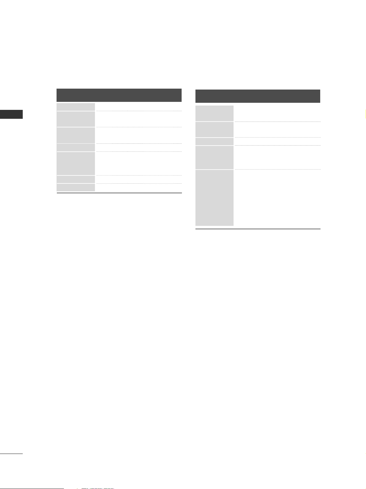
Supported Display Resolution
Resolution
720x400
640x480
Horizontal
Frequency(kHz)
Vertical
Frequency(Hz)
800x600
832x624
1024x768
1280x768
1360x768
RGB[PC] / HDMI[PC] mode
640x480
720x480
720x576
1280x720
1920x1080
31.469
31.469
31.47
31.50
31.25
37. 50
44.96
45.00
33.72
33.75
28.125
27.00
56.25
67. 433
67. 500
HDMI[DTV] mode
Resolution
Horizontal
Frequency(kHz)
Vertical
Frequency(Hz)
31.468
31.469
37. 500
37. 879
46.875
49.725
48.363
56.476
60.023
47. 693
47. 649
70.08
59.94
75.00
60.31
75.00
74.55
60.00
70.00
75.03
59.99
59.94
59.94
60.00
59.94
60.00
50.00
50.00
59.94
60.00
59.94
60.00
50.00
24.00
50.00
59.94
60.00
EXTERNAL EQUIPMENT SETUP
23
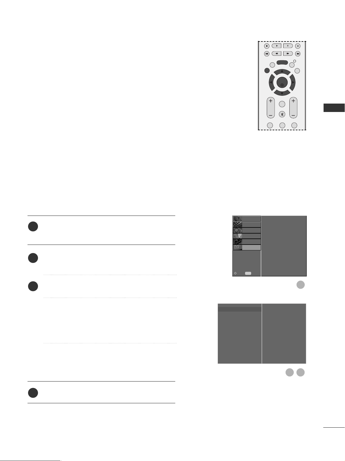
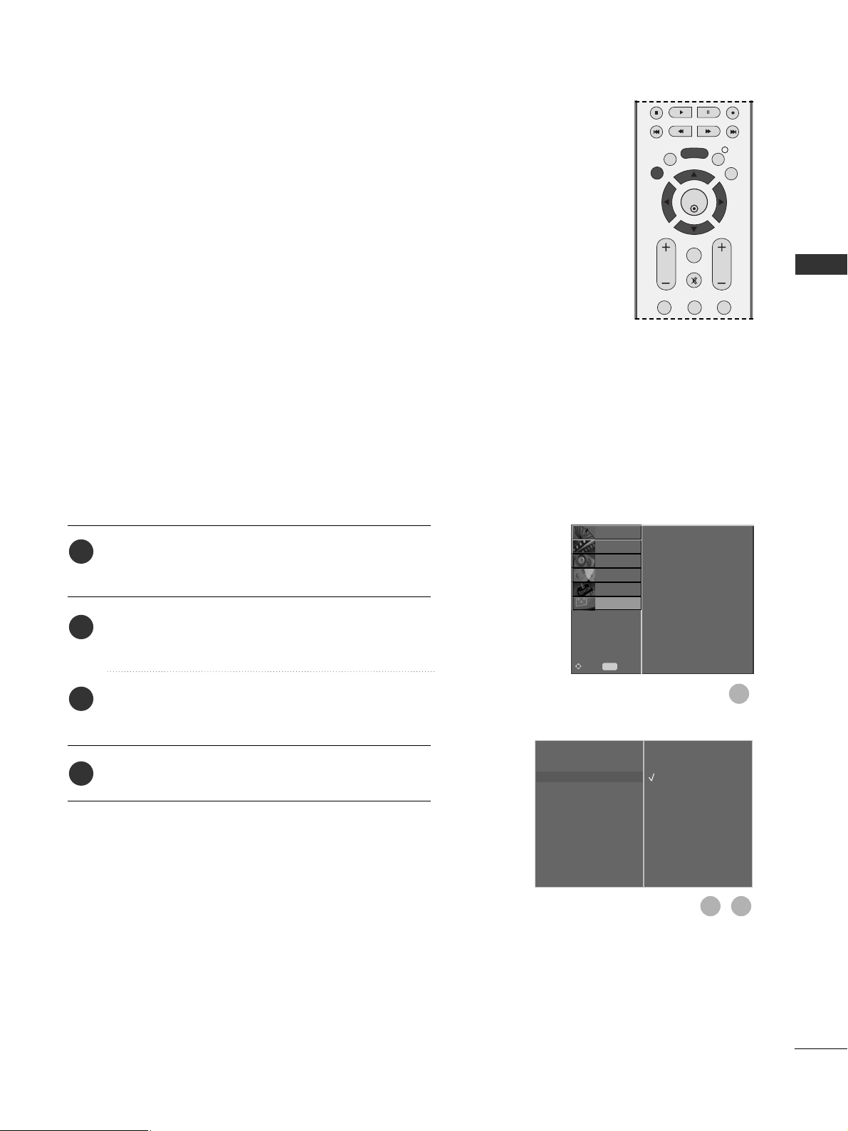
Screen Setup for PC mode
Automatically adjusts picture position and minimizes image
instability. After adjustment, if the image is still not correct, your
TV is functioning properly but needs further adjustment.
Auto configure
This function is for automatic adjustment of the screen position,
clock, and phase. The displayed image will be unstable for a few
seconds while the auto configuration is in progress.
Press the MENU button and then
D
or
E
button to
select the SCREEN menu.
Press the
G
button and then
D
or
E
button to select
Auto Config..
Press the
G
button to start Auto Config..
• When Auto Config. has finished, OK will be shown
on screen.
• If the position of the image is still not correct, try
Auto adjustment again.
• If picture needs to be adjusted again after Auto
adjustment in RGB (PC), you can adjust the
Manual Config..
Press the EXIT button to return to normal TV viewing.
Auto Configure (RGB [PC] mode only)
Auto Config. G
Manual Config.
XGA Mode
Aspect Ratio
Reset
To Set
1
3
2
1
2
3
4
Auto Config.
Manual Config.
XGA Mode
Aspect Ratio
Reset
SETUP
O
PICTURE
O
Prev.
MENU
Move
AUDIO
O
TIME
O
OPTION
O
SCREEN G
EXTERNAL EQUIPMENT SETUP
EXIT
BACK
MENU
INFO i
GUIDE
VOL PR
123
OK
FAV
MUTE

24
EXTERNAL EQUIPMENT SETUP
If the picture is not clear after auto adjustment and especially if
characters are still trembling, adjust the picture phase manually.
To correct the screen size, adjust Clock.
This function works in the following mode : RGB[PC].
Clock This function is to minimize any vertical bars or stripes
visible on the screen background the horizontal screen
size will also change.
Phase This function allows you to remove any horizontal noise
and clear or sharpen the image of characters.
H-Position / V-Position This function is to adjust picture to
left/right and up/down as you prefer.
Press the MENU button and then
D
or
E
button to
select the SCREEN menu.
Press the
G
button and then
D
or
E
button to select
Manual Config..
Press the
G
button and then
D
or
E
button to select
Phase, Clock, H-Position or V-Position.
Press the
F
or
G
button to make appropriate
adjustments.
Press the EXIT button to return to normal TV viewing.
Adjustment for screen Phase, Clock, Position
Auto Config.
Manual Config.
G
XGA Mode
Aspect Ratio
Reset
Phase
Clock
H-Position
V-Position
0
0
0
0
1
1
2
3
4
5
Auto Config.
Manual Config.
XGA Mode
Aspect Ratio
Reset
SETUP
O
PICTURE
O
Prev.
MENU
Move
AUDIO
O
TIME
O
OPTION
O
SCREEN G
3 4
2
OK
EXIT
VOL PR
GUIDE
BACK
MENU
123
MUTE
INFO i
FAV
EXTERNAL EQUIPMENT SETUP
25
To view a normal picture, match the resolution of RGB mode
and selection of XGA mode.
This function works in the following mode: RGB[PC] mode
Press the MENU button and then
D
or
E
button to
select the SCREEN menu.
Press the
G
button and then
D
or
E
button to select
XGA Mode.
Press the
G
button and then
D
or
E
button to select
the desired XGA resolution.
Press the EXIT button to return to normal TV viewing.
Selecting Wide XGA mode
Auto Config.
Manual Config.
XGA Mode
G
Aspect Ratio
Reset
1024 X 768
1280 X 768
1360 X 768
1
1
2
3
4
Auto Config.
Manual Config.
XGA Mode
Aspect Ratio
Reset
SETUP
O
PICTURE
O
Prev.
MENU
Move
AUDIO
O
TIME
O
OPTION
O
SCREEN G
3
2
EXTERNAL EQUIPMENT SETUP
OK
EXIT
VOL PR
GUIDE
BACK
MENU
123
MUTE
INFO i
FAV
26
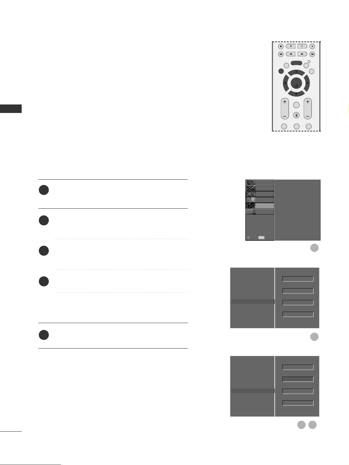
This function operates in current mode.
To initialize the adjusted value
Press the MENU button and then
D
or
E
button to
select the OPTION menu.
Press the
G
button and then
D
or
E
button to select
Factory Mode.
Press the
G
button and then
D
or
E
button to select
Factory Reset.
Press the OK button.
The message “If you enter a password, all user
setting will be reset” will appear.
Use NUMBER buttons to input a 4-digit password.
Initializing (Reset to original factory settings)
1
2
3
4
5
Language
Country
Lock System
Parental Control
Input Label
SIMPLINK
Factory Mode
G
Set ID
Factory Reset
ISM Method
Low Power
1
2
Language
Country
Lock System
Parental Control
Input Label
SIMPLINK
Factory Mode
SETUP
O
PICTURE
O
SCREEN
O
Prev.
MENU
Move
AUDIO
O
TIME
O
OPTION G
Language
Country
Lock System
Parental Control
Input Label
SIMPLINK
Factory Mode
Set ID
Factory Reset
ISM Method
Low Power
OK
4
3
OK
Normal
Off
1
Normal
Off
1
OK
EXIT
VOL PR
GUIDE
BACK
MENU
123
MUTE
INFO i
FAV
EXTERNAL EQUIPMENT SETUP
27
WATCHING TV / PROGRAMME CONTROL
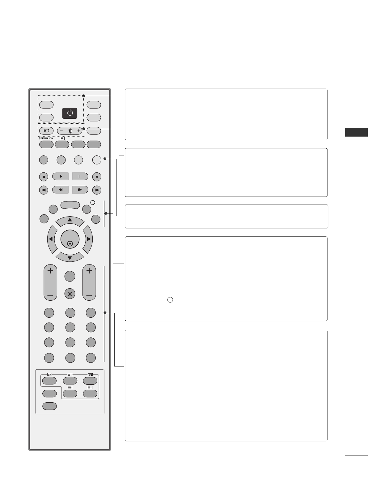
REMOTE CONTROL KEY FUNCTIONS
When using the remote control, aim it at the remote control sensor on the TV.
OK
INPUT MODE
TV
D/A
DVD
EXIT
VOL PR
GUIDE
BACK
MENU
RATIO
I/II
VCR
POWER
123
456
789
0
Q.VIEW
LIST
INDEX
SLEEP
HOLD
REVEAL
?
SUBTITLE
TEXT
INPUT
BRIGHT
MUTE
TV/RADIO
UPDATE
SIMPLINK
INFO i
FAV
TIME
POWER
D/A INPUT
TV/RADIO
Switches the TV on from standby or off to standby.
Selects digital or analogue mode.
Switches the TV on from standby.
Selects Radio or TV channel in digital mode.
INPUT
Brightness
adjustment
External input mode rotate in regular sequence.
Switches the TV on from standby.
Adjusts screen brightness.
This returns to the default settings brightness by
changing mode source.
Coloured
buttons
These buttons are used for teletext (on TELETEXT
models only) or
PPrrooggrraa mm mm ee eeddiitt
.
EXIT
BACK
MENU
INFO i
GUIDE
Clears all on-screen displays and returns to TV viewing
from any menu.
Allows the user to move back one step in an interactive
application, EPG or other user interaction function.
Selects a menu.
Shows the present screen information.
Shows programme schedule.
VOLUME UP
/DOWN
FAV
MUTE
Programme
UP/DOWN
0~9 number
button
LIST
Q.VIEW
Adjusts the volume.
Displays the selected favourite programme.
Switches the sound on or off.
Selects a programme.
Selects a programme.
Selects numbered items in a menu.
Displays the programme table.
Returns to the previously viewed programme.
WATCHING TV / PROGRAMME CONTROL
28
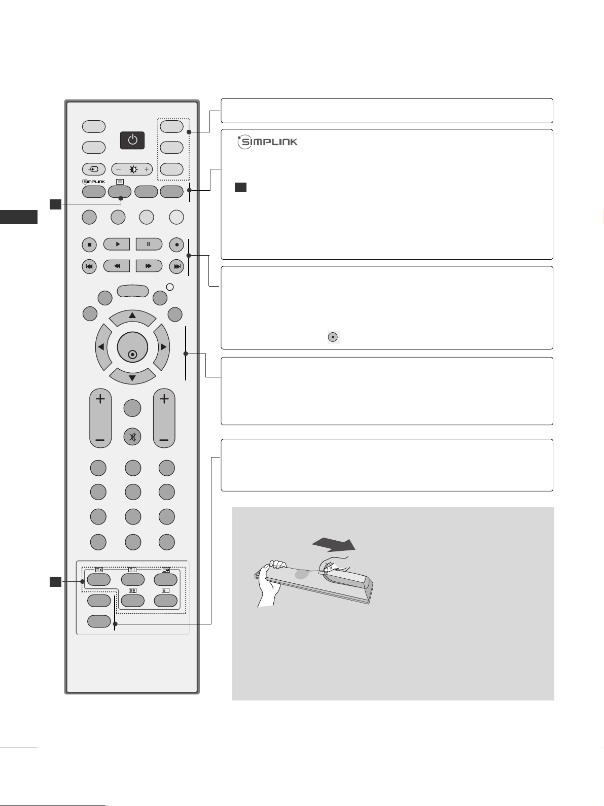
WATCHING TV / PROGRAMME CONTROL
WATCHING TV / PROGRAMME CONTROL
Installing Batteries
■
Open the battery compartment cover on the back and install the
batteries matching correct polarity (+with +,-with -).
■
Install two 1.5V AA batteries. Do not mix old or used batteries
with new ones.
■
Close cover.
OK
INPUT MODE
TV
D/A
DVD
EXIT
VOL PR
GUIDE
BACK
MENU
RATIO
I/II
VCR
POWER
123
456
789
0
Q.VIEW
LIST
INDEX
SLEEP
HOLD
REVEAL
?
SUBTITLE
TEXT
INPUT
BRIGHT
MUTE
TV/RADIO
UPDATE
SIMPLINK
INFO i
FAV
TIME
1
1
MODE
Selects the remote operating modes.
TELETEXT
BUTTONS
RATIO
I/II
See a list of AV devices connected to TV.
When you toggle this button, the Simplink menu appears
at the screen. (
G p.47)
These buttons are used for teletext.
For further details, see the ‘Teletext’ section.
Selects your desired picture format.
Selects the sound output.
THUMBSTICK
(Up/Down/Left
Right)
OK
Allows you to navigate the on-screen menus and adjust
the system settings to your preference.
Accepts your selection or displays the current mode.
SLEEP
SUBTITLE
Sets the sleep timer.
Recalls your preferred subtitle in digital mode.
VCR/DVD
control buttons
Controls some video cassette recorders or DVD players
when you have already selected DVD or VCR mode button.
Control connected AV devices by pressing the
DD
or EEor
FF
or GG, OK buttons and buttons for play, stop, pause,
fast reverse, fast forward, chapter skip.
(The button does not provide such functions.)
1
 Loading...