

Page 1

PLASMA TV
MANUAL DE SERVIÇO
ATENÇÃO
Antes de reparar este chassis, leia as PRECAUÇÕES DE SEGURANÇA
contidas neste manual.
CHASSIS : PB82C
MODELO : 50PG60D 50PG60D-SA
website:http://biz.LGservice.com
Internal Use Only
Page 2

- 2 -
Copyright © 2008 LG Electronics. Inc. All right reserved.
Only for training and service purposes
LGE Internal Use Only
CONTEÚDO
CONTEÚDO............................................................................................................... 2
PRECAUÇÕES DE SEGURANÇA ............................................................................3
INSTRUÇÕES DE REGULAÇÃO ..............................................................................4
GUIA DE RESOLUÇÃO DE PROBLEMAS ...............................................................9
DIAGRAMA DE BLOCOS ........................................................................................40
VISTAS EXPLODIDAS............................................................................................. 42
LISTA DAS VISTAS EXPLODIDAS..........................................................................43
DIAGRAMA ELÉTRICO................................................................................................
PAINEL DE CIRCUITO IMPRESSO .............................................................................
Page 3
- 3 -
Copyright © 2008 LG Electronics. Inc. All right reserved.
Only for training and service purposes
LGE Internal Use Only
PRECAUÇÕES DE SEGURANÇA
ADVERTÊNCIA : Antes de reparar este chassis., leia as “ PRECAUÇÕES DE RADIAÇÃO POR RAIO X “, “ INSTRUÇÕES
DE SEGURANÇA “ e “ AVISO SOBRE SEGURANÇA DE PRODUTOS “.
Muitas partes elétricas e mecânicas neste chassis, tem características relacionadas com a segurança. Estas características
frequentemente não são verificadas nas inspeções visuais e a proteção que proporcionam contra a RADIAÇÃO DE RAIO “ X “ nem
sempre se obtem utilizando componente com maior potência ou de maior isolação. As peças que têm essas características de
segurança são identificadas por uma marca [ ] impressa sobre o diagrama esquemático e a marca [
★ ] impressa na lista de
partes elétricas. Antes de substituir algum destes componentes, leia cuidadosamente este manual. O uso de peças de reposição que
não tenham as mesmas características de segurança, como especificado na lista de material de reposição, pode gerar Radiação de
Raios “X”.
1. Quando o receptor está em operação, são geradas tensões
potencialmente altas em torno de 25-29 kV. Operar o receptor
fora de seu gabinete ou com a tampa traseira removida pode
causar perigo de choque elétrico.
(1) Ninguém deverá tentar reparar o aparelho sem estar
familiarizado com as precauções que são necessárias
quando se trabalha com um equipamento de alta tensão.
(2) Sempre descarregue o anodo do cinescópio ao terra para
evitar o risco de choque elétrico antes de remover o conector
do anodo (chupeta de alta tensão).
(3) Descarregue completamente o potencial do cinescópio
antes de manuseá-lo. O cinescópio é de alto vácuo, e se
quebrar, os fragmentos de vidro são expelidos violentamente.
2. S e queimar algúm fusível deste receptor de televisão,
substitua-o por outro especificado na lista de peças elétricas.
3. Quando substituir placas de circuito impresso ou módulos, fixe
seus fios nos terminais antes de soldar.
4. Quando substituir uma resistência de potência (resistor de
película de óxido metálico) no painel de circuito impresso,
mantenha os seus terminais com 10mm de distância do
painel.
5. Mantenha os fios e cabos distantes de componentes de alta
potência e de alta temperatura.
6. Este receptor deve operar em redes de 100 a 240 V AC.
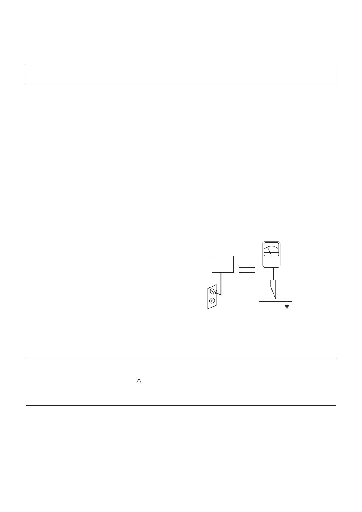
7. Antes de devolver este aparelho ao cliente, faça uma
verificação de fuga de corrente sobre as partes metálicas
expostas do gabinete, tais com antenas, terminais, cabeças
de parafusos, tampas de metal, alavancas de controle, etc., e
certifique-se de que o aparelho funciona sem perigo de
choque elétrico. Ligue o cabo de rede do aparelho
diretamente a uma tomada de força de 100-240 V AC. Não
utilize um transformador de isolação durante este teste.
Utilize um voltímetro de no mínimo 1KW por Volt de
sensibilidade, da forma que se segue.
Quando a unidade estiver conectada ao AC, pulse o
comutador primeiramente em “ON” (ligado) e em seguida em
“OFF” (desligado), meça desde um ponto de terra conhecido
(tal como um terminal de terra central da rede elétrica) a
todas as partes metálicas expostas do televisor ( antenas,
teclas metálicas, capas metálicas, alavancas de controle,
etc..) especialmente qualquer parte metálica que possa
oferecer um caminho ao chassis. Nenhuma medição de
corrente elétrica deve exceder 0,5 mA. Repita a prova
mudando a posição do pluque de rede na tomada AC.
Qualquer medição que não esteja dentro dos limites aqui
especificados, representam risco potencial de choque elé
trico que deve ser sanado antes que o aparelho retorne ao
cliente.
INSTRUÇÕES DE SEGURANÇA
AVISO SOBRE SEGURANÇA DE PRODUTO
DEVICE
UNDER
TEST
TEST ALL
EXPOSED MET AL
SURFA CES
2-WIRE CORD
ALSO TEST WITH
PLUG REVERSED
(USING AC ADAPTER
PLUG AS REQUIRED)
EAR TH
GROUND
LEAKAGE
CURRENT
TESTER
(READING SHOULD
NO T BE ABOVE
0.5mA)
+-
Aparelho
a ser
examinado
Probador
de fuga de
corriente
A leitura não deve
exceder 0.5mA
Prove todas as
superficies
metálicas
Também prove com
o plugue de rede
invertendo a
polaridade
Terra
Page 4
- 4 -
Copyright © 2008 LG Electronics. Inc. All right reserved.
Only for training and service purposes
LGE Internal Use Only
INSTRUÇÕES DE REGULAÇÃO
1. Application Object
These instructions are applied to all of the PDP TV, PB82C
2. Notes
(1) Because this is not a hot chassis, it is not necessary to use
an isolation transformer. However, the use of isolation
transformer will help protect test equipment.
(2) Adjustments must be done in the correct order.
(3) The adjustments must be performed in the circumstance of
25±5°C of temperature and 65±10% of relative humidity if
there is no specific designation.
(4) The input voltage of the receiver be must kept 100~220V,
50/60Hz when adjusting.
(5) The receiver must be operational for about 15 minutes
prior to the adjustments.
3. Component 480i/1080p RGB
1080p Manual Adjustment
3-1. Synopsis
Component 480i/1080p RGB 1080p adjustment to set the
black level and the Gain to optimum.
3-2. Test Equipment
(1) Service R/C
(2) 801GF(802B, 802F, 802R) or MSPG925FA Pattern
Generator (480i/1080i The Horizontal 100% Color Bar
Pattern adjust to within 0.7±0.1Vp-p)
[ Because the above pattern can differ by the model and
pattern for each device, you must check the pattern first.
3-3. ADC 480i Component1 Adjustment
(1) Check the connection Component1 to the Test Equipment.
(MSPG-925FA => Model: 209, Pattern: 65)
(2) Select Component1 as the input with 100% Horizontal
Color Bar Pattern(HozTV31Bar) in 480i Mode and select
‘Normal’ in screen.
(3) After receiving signal for at least 1 second, press the ADJ
Key on the Service R/C to enter the ‘Ez - Adjust’ and select
the ‘3. ADC 480i Comp1’.
Pressing the Enter Key to adjust automatically.
(4) When the adjustment is over, 'ADC Component1 Success’
is displayed.
(5) If the adjustment has errors, 'ADC Component1 480i Fail’
is displayed. And error massage(‘Component1 Not
Connected’ or ‘Not Valid Format’ or ‘Check Signal Status’)
is displayed for 1 second.
3-4. ADC 1080p or 1080p Component1/
RGB Adjustment
(1) Check the connection Component1, RGB to the Test
Equipment (MSPG-925FA => Model: 225, Pattern: 65)
(2) Select Component1 as the input with 100% Horizontal
Color Bar Pattern(HozTV31Bar) in 1080p Mode and select
‘Normal’ in screen.
(3) After receiving signal for at least 1 second, press the ADJ
Key on the Service R/C to enter the ‘Ez - Adjust’ and select
the ‘4. ADC 1080p Comp1/RGB’.
Pressing the Enter Key to adjust automatically component1.
(4) When the adjustment is over, 'ADC Component1 Success’
is displayed. If the adjustment has errors, 'ADC
Component1 1080p Fail’ is displayed.
(5) After the Component1 adjustment is over, convert the
RGB-DTV Mode and start RGB adjustment.
When the adjustment is over, 'ADC RGB 1080P Success’
is displayed.
(6) Readjust after confirming the case Pattern or adjustment
condition where the adjustment errors.
Error massage is ‘Component1 Not Connected’ or ‘Not
Valid Format’ or ‘Check Signal Status’.
(7) After adjustment is complete, exit the adjustment mode by
pressing the ADJ KEY.
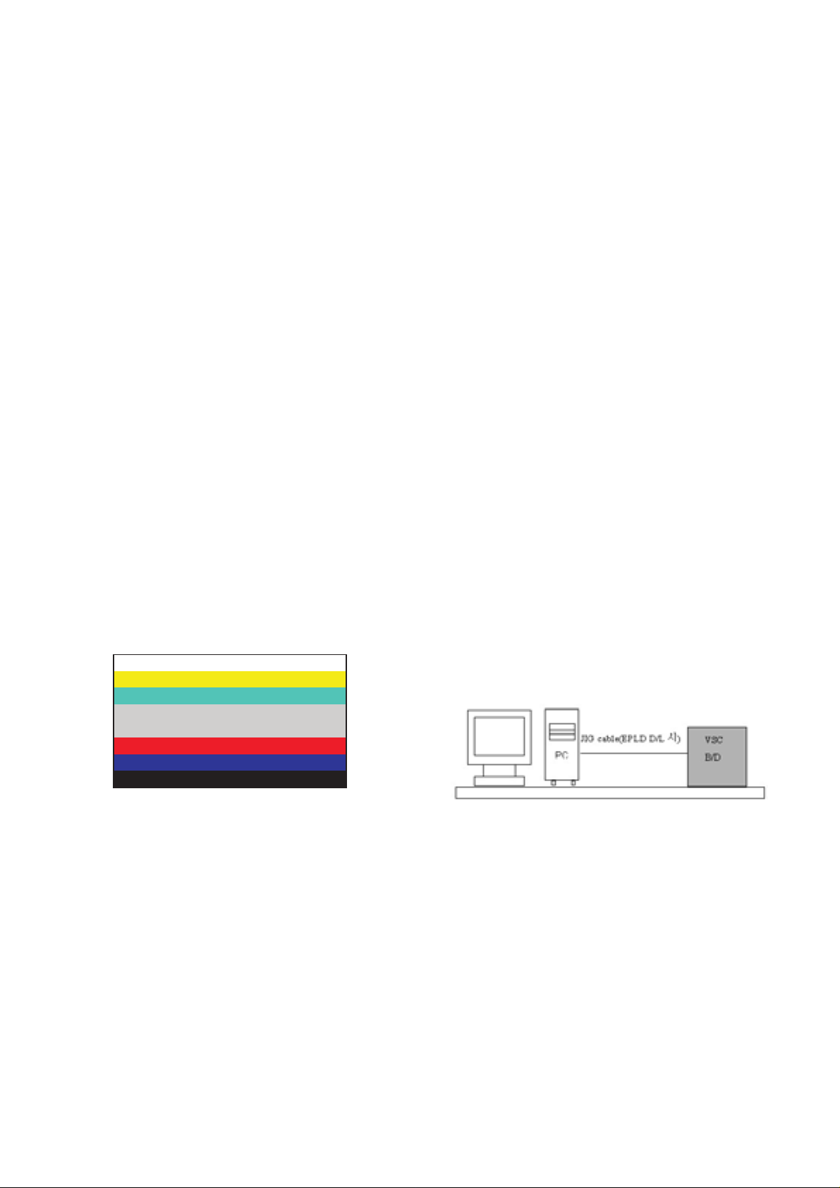
4. EPLD Download
(1) Required Test Equipment: PC, Jig for download
(2) Connect the power of VSC B/D.
(3) Execute download program(iMPACK) of PC.
(4) After execute Programmer, click the Program icon.
(5) After enter, exit.
<Fig. 1> ADC Adjustment Pattern: 480i, 1080p/ 60Hz Pattern
Page 5

- 5 -
<HEAT RUN>
O Preliminary action is applied to the test for afterimage
discharge detection, and 100% FULL WHITE PATTERN
must be operated automatically.
(1) Pressing Power On key on the adjustment R/C
(2) Full Test Pattern(2 min 30sec) --> Full Black
Pattern(30sec) --> Full White Pattern
(Full White Pattern when the main power is turned on
again after being turned off)
(3) Pattern Mode is deselected by pressing CH +/-, Exit Key.
[ Set is activated HEAT-RUN without signal generator in this
mode.
5. Voltage Adjustment(50” Model)
5-1. Test Equipment
(1) D.M.M 1EA
(2) Voltage adjustment bar
5-2. Connection Diagram for Measuring
Refer to Fig 1.
5-3. Adjustment
(1) Va Voltage Adjustment
1) Connect + terminal of D.M.M to Va pin of P811 and
connect – terminal to GND pin of P811.
2) Adjust VR901 voltage to match that of the label on the
Top/Right of the panel. (Deviation : ±0.5V)
(2) Vs Voltage Adjustment
1) Connect + terminal of D.M.M to Vs pin of P811 and
connect – terminal to GND pin of P811.
2) Adjust VR951 voltage to match that of the label on the
Top/Right of the panel. (Deviation : ±0.5V)
Copyright © 2008 LG Electronics. Inc. All right reserved.
Only for training and service purposes
LGE Internal Use Only
Test Pattern 2min 30sec
Test Pattern 30sec
If you turn on a still screen more than 20 minutes (Especially
Digital pattern(13 CH), Cross Hatch Pattern), an afterimage
may occur in the black level part of the screen.
Each PCB Assy must be checked by Check JIG Set before
assembly. (Especially, be careful Power PCB Assy which can
cause Damage to the PDP Module.)
<Fig. 1> Connection Diagram for Measuring (Power Board):
LGIT 50” EAY39190301
Page 6
- 6 -
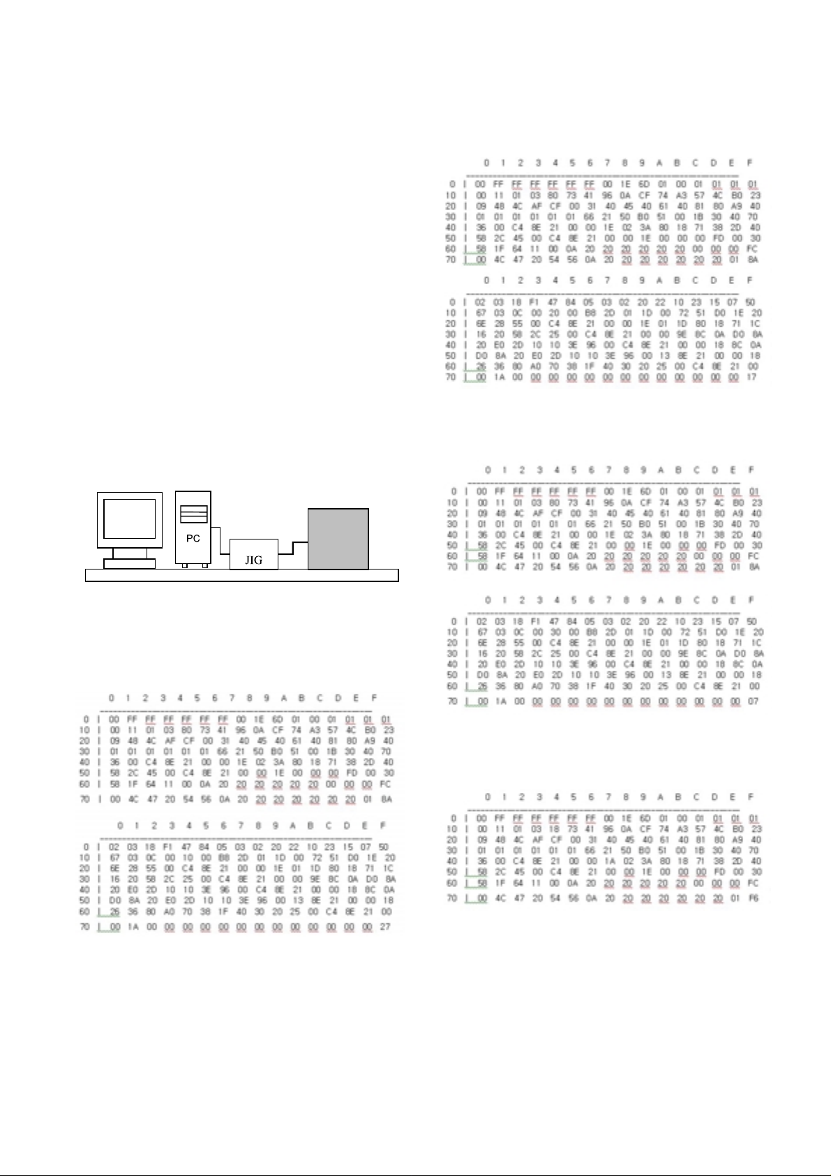
6. EDID(The Extended Display
Identification Data)/DDC
(Display Data Channel) Download
It is the feature to implement the “Plug and Play” which
automatically reconfigures the user’sl environment to directly
use by exchanging information without any command directly
to the PC or the monitor by the user, which is established by
the VESA
6-1. HDMI EDID Data Input
(1) Required Test Equipment
1) PC, Jig for adjusting DDC. (PC serial to D-sub
Connection equipment)
2) S/W for writing DDC(EDID data write & read)
3) D-Sub cable
4) Jig for HDMI Cable connection
(2) Preparation for Adjustments &
Setting of Device
1) Set devices as below and turn on the PC and JIG.
2) Open S/W for writing DDC (EDID data write & read).
(operated in DOS mode)
6-2. EDID DATA for 50PG60D-SA
:EDID for HDMI-1 (DDC (Display Data Channel) Data)
EDID table =
:EDID for HDMI-2 (DDC (Display Data Channel) Data)
EDID table =
:EDID for HDMI-3 (DDC (Display Data Channel) Data)
EDID table =
:EDID Data for RGB
EDID table =
Copyright © 2008 LG Electronics. Inc. All right reserved.
Only for training and service purposes
LGE Internal Use Only
LCD TV SET
(or Digital Board)
Page 7
- 7 -
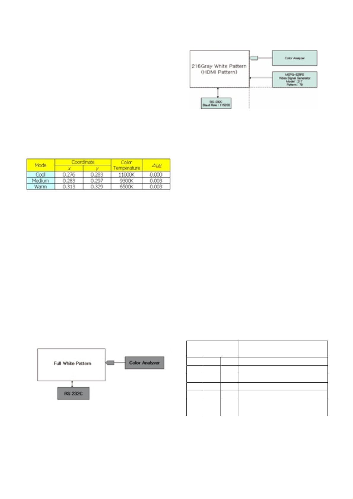
7. Adjustment of White Balance
7-1. Required Test Equipment
(1) Color Analyzer : CA-210 (CH 10), CA-100, CA-100+
=> To adjust color temperature of PDP, CS-1000 is the
Color Analyzer(CA-210) and should be set to use CH 10
in which white, red, green, and blue color are corrected.
Conduct the adjustment according to the coordinates for
White Balance adjustment in the table below.
(2) Computer for adjusting (necessary for the automatic
adjustment, possible to communicate with the RS-232C,
Baud Rate : 115200)
(3) Video Signal Generator MSPG-925F 720p, 216Gray
(Model :217, Pattern 78)
[Full white 216gray]
[
Adjustment Environment and Reference
1) Environment illuminance
Adjust it to 10 LUX or less at the place where the light
source such as lamp should be blocked at maximum.
2) Probe location
- PDP: Locate the Color Analyzer (CA-100, CA-100+,
CA210) close to the module surface to measure and
adjust
- LCD: Maintain the Color Analyzer (CA-210) close to the
module surface by 10cm or less and keep the probe of
the Color Analyzer perpendicular to the module surface
(80°~ 100°).
7-2. Connection Diagram of Equipment
for Measuring
(Automatic Adjustment)
Use the internal pattern to adjust White Balance. The pattern
is automatically given when the automatic adjustment device
is connected or when a user presses ADJ on the remote
controller to start Ez Adjust and then selects 6.White-Balance.
7-3. White Balance Adjustment Method
Basically it uses the internal pattern but when internal pattern
is not possible, you can select HDMI input for adjustment.
Through the option at the most bottom part of the Ez Adjust
Menu 7.White Balance menu, you can select NONE, INNER
and HDMI, and the default is set to INNER. When the
adjustment cannot be done with the internal pattern, you can
select HDMI input for adjustment.
For manual adjustment, press the ADJ KEY of the adjustment
R/C to enter Ez Adjust 7.White-Balance, and the pattern is
automatically displayed. (When you set the Option to INNER,
the default is always set to INNER)
(1) Connect the set according to the internal pattern or HDMI
input in accordance with measuring device connection
diagram.
(2) Set the Baud Rate of RS-232C to 115200. It is set to
115200 as default.
(3) Connect the RS-232C Cable to the set.
(4) Connect the HDMI Cable to the set. (Limited to the set with
HDMI option)
(5) Select and adjust the model applicable to PB82C chassis
from the adjuster.
7-4. Automatic Adjustment
(1) Execute POWER ON(Â) of the adjustment R/C to execute
automatic adjustment or set the Baud Rate to 115200.
(2) Always start adjustment with “wb 00 00” and end
adjustment with “wb 00 ff” (Adjust the offset if necessary)
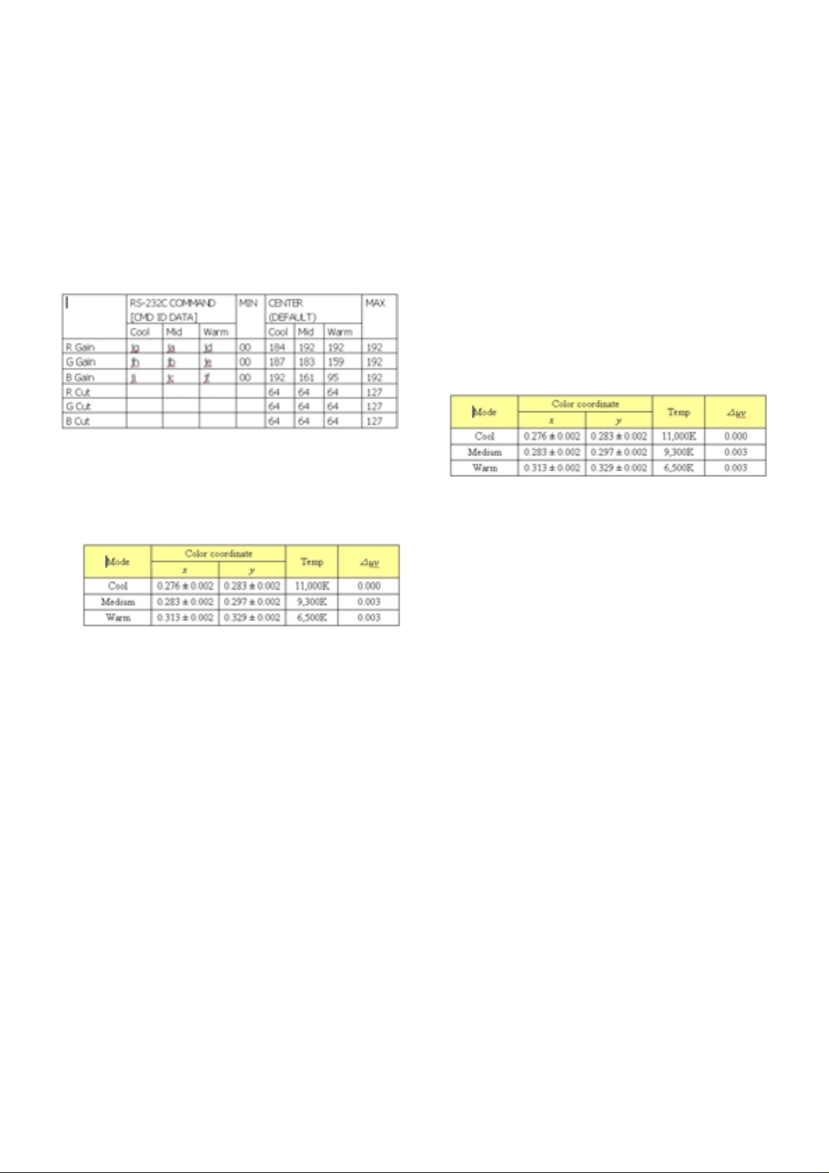
(3) RS-232C command used for the automatic adjustment
Copyright © 2008 LG Electronics. Inc. All right reserved.
Only for training and service purposes
LGE Internal Use Only
(internal pattern)
Connection Diagram for Internal Pattern
Connection Diagram for HDMI Input
wb
wb
wb
wb
wb
wb
00
00
00
00
00
00
00
10
1f
20
2f
ff
White Balance Adjustment Start
Gain Adjustment Start(Internal white pattern)
Gain Adjustment End
Offset Adjustment Start(Internal white pattern)
Offset Adjustment End
White Balance Adjustment End
(Disappear Internal pattern)
RS-232C COMMAND
[CMD ID DATA]
Meaning
Page 8
- 8 -
Ex) Wb 00 00-----white balance Automatic Adjustment Start
Wb 00 10-----Gain Adjustment start (Internal pattern)
Ja 00 ff------Adjustment Data
Jb 00 c0
...
...
Wb 00 1f-----Gain Adjustment End
*(wb 00 20(Start), wb 00 2f(End))----- When adjust Off-set
Wb 00 ff------White Balance Automatic Adjustment End
(Disappear Inside pattern)
(4) Adjustment Map
(5) Execute POWER ON(
Â) of the adjustment R/C to execute
automatic adjustment.
- Set the Baud Rate to 115200.
- Always start adjustment with “wb 00 00” and end
adjustment with “wb 00 ff”
- Adjust the offset if necessary
7-5. Manual Adjustment
(1) Required Test Equipment: CA-210 (CH-10), CA-100(CH-
10), CA-100+(CH-10)
=> To adjust color temperature of PDP, CS-1000 is the
Color Analyzer and should be set to use CH 10 in which
white, red, green, and blue color are corrected. Conduct
the adjustment according to the coordinates for White
Balance adjustment in the table below.
(2) Enter the ‘Ez - Adjust’ by pressing the ADJ on the Service
R/C.
(3) Select 10.TEST PATTERN using the CH + / - KEY and
press the Enter KEY to execute a heat run for more than
30 minutes.
(4) Zero Calibrate CA-100+/CA-100 Probe, and stick the
sensor to the center of PDP module surface when you
adjust.
Execute a Zero Calibration for CA-210 Probe and put it at
distance of less than 10Cm from the PDP module surface
center during the adjustment.
(5) Select ‘7. White-Balance’ of ‘Ez - Adjust’ by pressing the
ADJ KEY on the Service R/C. Then enter adjustment mode
by pressing the Right KEY (
G
) .
(The internal pattern of full white appears by pressing
G
)
(6) The adjustment is conducted in three levels of color
temperature; COOL, MEDIUM, and WARM.
1) When R GAIN is set to 192
- Control G GAIN and B GAIN by lowering from 192.
2) When B GAIN is set to 192
- Control R GAIN and G GAIN by lowering from 192.
3) When G GAIN is set to 192
- Control R GAIN and B GAIN by lowering from 192.
One of R Gain / G Gain / B Gain should be kept on 192,
and adjust other two lower than 192.
(When R/G/B GAIN are all 192, it is the FULL DYNAMIC
Range of Module)
(7) Use the Vol. +, - key for adjustment.
(8) When the adjustment is completed, press the ENTER (
Á
KEY) button to move to the Ez –Adjust screen. Press the
ADJ KEY to exit the adjustment mode.
Copyright © 2008 LG Electronics. Inc. All right reserved.
Only for training and service purposes
LGE Internal Use Only
Page 9

- 9 -
Copyright © 2008 LG Electronics. Inc. All right reserved.
Only for training and service purposes
LGE Internal Use Only
GUIA DE RESOLUÇÃO DE PROBLEMAS
Flash
(32MB)
DDR1(128MB)
(16Mx16x4)
DDR1(128MB)
(16Mx16x4)
TEA6420
Audio
SW
MTV416
(Micom )
NTP3000A
(Digital AMP)
64Bit I/F
RGB-PC
HDMI
1/2/3
COMP 1
COMP 2
AV1
AV2
RGB-PC
I2S
MCLK
Digital out
COMP1
COMP2
AV1
AV2
BCM7412
(MPEG4
Decoder)
Analog
/Digital
Tuner
TC90512
DVI
I2S
SIF
SPDIF Out
CVBS
CVBS/Y/C
Y/Cb/Cr
R/G/B
DDR1
(32MB)
CS5340
L/R
Serial TP
20bits
12bit YCbCr 4:2:2
NIM TUNER
TMDS_RX+-
EPM240F
MNT out (Audio Only)
TMDS351
(3x1,S/W)
CVBS/Y/C
MC33078
(AMP)
L/R
RS232
RX/TX
DVI
4:2:2 20bit YCbCr
Full HD(1080P)
WXGA(768P)
RF
Switch
DM1/DP1
Serial
TP
74HC04
SPDIF Out
(Coaxial)
Video
Front
End
Dual
HDMI
Rx
HD/SD
Video
Encoder
Audio
DSP
USB2.0
PKT
HSX
PCI/
EBI
HD-DVI
IB0
Parse2
RSBUF
XCBUF
RMX0
BCM3553
Local KEY
24C16
74LVC14APW
X-tal(54M)
Reset
KIA7029
NVRAM
I2C
Power-Up Boot Fail Trouble Shooting
LCD Only
Page 10
- 10 -
Copyright © 2008 LG Electronics. Inc. All right reserved.
Only for training and service purposes
LGE Internal Use Only
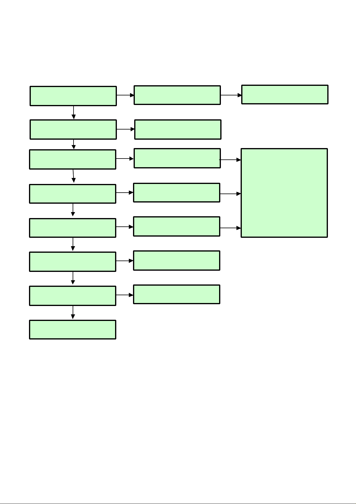
Power-Up Boot Fail Trouble Shooting
Check P801 All
Voltage Level (16V, 12V, 5V)
Check Power connector
OK ?
Replace Power board
Y
NY
Check IC801 #2 Pin / L805
Voltage Level 3.3V
Replace IC801/ L805 &
Recheck
Y
N
Check IC803 #5 Pin / L807
Voltage Level 2.6V
Replace IC803 or L807 &
Recheck
Y
N
Check C830, C853, C856
Voltage Level 1.2V
Replace IC802 or IC805 &
Recheck
Y
N
Check X200 Clock
54MHz
Replace X200
Y
N
Check R154 Clock
33MHz
Maybe BCM3553 has troubles.
Y
N
Replace IC101 Flash Memory
N
N
N
Check Micom IC407
Redownload or replace
Check Q801 Output
Voltage Level (5V)
C882, C880, C884,C885
Replace Q801
C882, C880, C884,C885 & Recheck
N
Y
Page 11
- 11 -
Copyright © 2008 LG Electronics. Inc. All right reserved.
Only for training and service purposes
LGE Internal Use Only
No OSD Trouble Shooting
Flash
(32MB)
DDR1(128MB)
(16Mx16x4)
DDR1(128MB)
(16Mx16x4)
TEA6420
Audio
SW
MTV416
(Micom )
NTP3000A
(Digital AMP)
64Bit I/F
RGB-PC
HDMI
1/2/3
COMP 1
COMP 2
AV1
AV2
RGB-PC
I2S
MCLK
Digital out
COMP1
COMP2
AV1
AV2
BCM7412
(MPEG4
Decoder)
Analog
/Digital
Tuner
TC90512
DVI
I2S
SIF
SPDIF Out
CVBS
CVBS
Y/Cb/Cr
R/G/B
DDR1
(32MB)
CS5340
L/R
Serial TP
20bits
12bit YCbCr 4:2:2
NIM TUNER
TMDS_RX+-
EPM240F
MNT out (Audio Only)
TMDS351
(3x1,S/W)
CVBS/Y/C
MC33078
(AMP)
L/R
RS232
RX/TX
DVI
Full HD(1080P)
WXGA(768P)
RF
Switch
DM1/DP1
Serial
TP
74HC04
SPDIF Out
(Coaxial)
Video
Front
End
Dual
HDMI
Rx
HD/SD
Video
Encoder
Audio
DSP
USB2.0
PKT
HSX
PCI/
EBI
HD-DVI
IB0
Parse2
RSBUF
XCBUF
RMX0
BCM3553
Local KEY
24C16
74LVC14APW
X-tal(54M)
Reset
KIA7029
NVRAM
I2C
LCD Only
4:2:2 20bit YCbCr
Page 12
- 12 -
Copyright © 2008 LG Electronics. Inc. All right reserved.
Only for training and service purposes
LGE Internal Use Only
No OSD Trouble Shooting
Check P902
#33(TXAC-) , #32(TXAC+) ,
#17(TXBC-) , #16(TXBC+)
Maybe BCM3553 has problems
Check LVDS Cable
Check PDP Module
Control board
Refer to Module CAS
Y
N
Y
Replace Cable
N
Y
Check PDP Vs,Va Voltage
Module 5V
Replace Power
N
Check P801 Disp_EN ,
VaVs ON, 5V_MNT
Check Micom Path
N
Y
Page 13
- 13 -
Copyright © 2008 LG Electronics. Inc. All right reserved.
Only for training and service purposes
LGE Internal Use Only
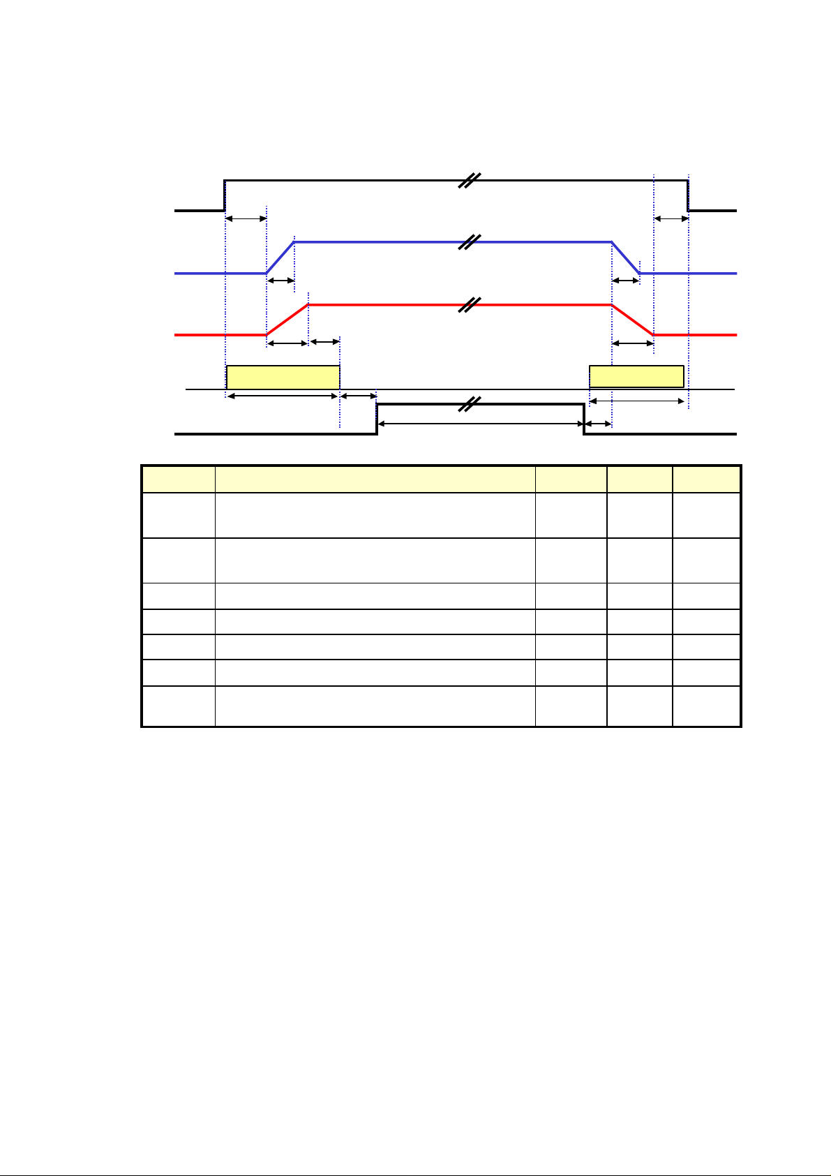
No OSD Trouble Shooting (Module Power Sequence)
Normal Display
Vcc
(5V)
Va
Vs
DISPEN
T
VaR
T
VsR
T
On
T
VaF
T
VsF
T
Off
☞1)
Power_on
3 Sec
Power_off
3 Sec
Min
100ms
Min.
2Frame
(Recommend: 2 sec)
msec50090Falling Time of Vs (90% to 10%)T
VsF
msec2000600
Time interval between 90% of Vcc and 90% of Vs
when Power On
T
on
+
T
VsR
msec800100Rising Time of Vs (10% to 90%)T
VsR
msec30050Falling Time of Va (90% to 10%)T
VaF
msec30010Rising Time of Va (10% to 90%)T
VaR
msec-20
Time interval between 10% of Vs and 90% of Vcc
when Power Off
T
Off
msec-500
Time interval between 90% of Vcc and 10% of Vs
when Power On
T
On
unitMax.Min.DescriptionSymbol
Page 14
- 14 -
Copyright © 2008 LG Electronics. Inc. All right reserved.
Only for training and service purposes
LGE Internal Use Only
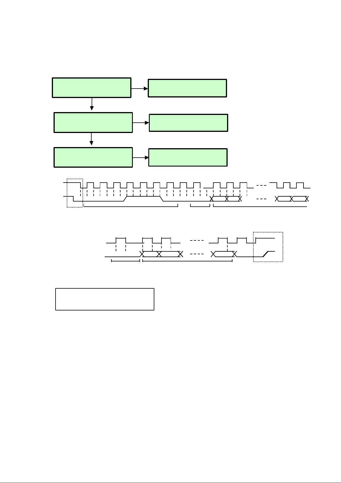
Module Control Trouble Shooting
Check the PDP Module Control
Board
Replace Module Control Board
N
Y
Check the IIC Tthe IIC Test
- Debug Menu IIC Test
Remove R937, R936
Check each IC sharing
IIC channel 2
N
Check P902 SCL,SDA line SCL,SDA
line R937, R936
Check Signal
N
Y
SCL (continue)
SDA (continue)
ACK
By Slave
9 1
D0
D7
9
ACK
By Slave
Command Data
for Addr
Stop
By Master
D6
SCL
8
SDA
00
111
A7W
Start
By
Master
Chip ID Address Byte
(0x1C)
ACK
By Slave
0
1
9 1
A6 A1 A0
Command Address
Addr=A[7:0]
0
Write
only
Master : Image Board
Slave : PDP Module
Page 15
- 15 -
Copyright © 2008 LG Electronics. Inc. All right reserved.
Only for training and service purposes
LGE Internal Use Only
Flash
(32MB)
DDR1(128MB)
(16Mx16x4)
DDR1(128MB)
(16Mx16x4)
TEA6420
Audio
SW
MTV416
(Micom )
NTP3000
(Digital AMP)
64Bit I/F
RGB-PC
HDMI
1/2/3
COMP 1
COMP 2
AV1
AV2
RGB-PC
I2S
MCLK
Digital out
COMP1
COMP2
AV1
AV2
BCM7412
(MPEG4
Decoder)
Analog
/Digital
Tuner
TC90512
DVI
I2S
SIF
SPDIF Out
CVBS
CVBS/Y/C
Y/Cb/Cr
R/G/B
DDR1
(32MB)
CS5340
L/R
Serial TP
20bits
12bit YCbCr 4:2:2
NIM TUNER
TMDS_RX+-
EPM240F
MNT out (Audio Only)
TMDS341A
(3x1,S/W)
CVBS/Y/C
MC33078
(AMP)
L/R
RS232
RX/TX
DVI
Full HD(1080P)
WXGA(768P)
RF
Switch
DM1/DP1
Serial
TP
Video
Front
End
Dual
HDMI
Rx
HD/SD
Video
Encoder
Audio
DSP
USB2.0
PKT
HSX
PCI/
EBI
HD-DVI
IB0
Parse2
RSBUF
XCBUF
RMX0
BCM3553
Local KEY
24C16
74LVC14APW
X-tal(54M)
Reset
KIA7029
NVRAM
I2C
Digital TV Video Trouble Shooting
4:2:2 20bit YCbCr
Page 16

- 16 -
Copyright © 2008 LG Electronics. Inc. All right reserved.
Only for training and service purposes
LGE Internal Use Only
Digital TV Video Trouble Shooting
Check RF Cable
Check TP Clock, Data, Sync
R925 (38.1MHz), R804, R803
Maybe Tuner(TU800) has problems
Check BCM3553 Output TP Clock,
Data, Sync
R153, R155, R152
Check BCM7412 Clock, Hsync, Vsync
R1088 (Typ . 74.25MHz), R1087, R1086
Y
Y
N
Check Tuner 5V Power
IC810 #3 Pin
Replace IC810
Y
N
Y
Maybe BCM3553(IC100) has problems
N
Maybe BCM7412(IC1000) has problems
N
Check PLD Clock, Hsync , Vsync
R1102 (Typ. 74.25MHz), R1100, R1101
Y
Redownload PLD file or replace
N
Maybe BCM3553(IC100) has problems
Y
Check D805 color
Bad Tuner. Replace Tuner.
None
red
Check BCM7412 Input Clock
R107 (27MHz)
Replace it
N
Y
Page 17

- 17 -
Copyright © 2008 LG Electronics. Inc. All right reserved.
Only for training and service purposes
LGE Internal Use Only
Clock Operate below 81Mbps
Valid Pin --> high Pull - up
DVI Output (DDR Mode)
Digital TV Video Trouble Shooting
Refer to BCM7412 Input / Output Signal
Page 18

- 18 -
Copyright © 2008 LG Electronics. Inc. All right reserved.
Only for training and service purposes
LGE Internal Use Only
Flash
(32MB)
DDR1(128MB)
(16Mx16x4)
DDR1(128MB)
(16Mx16x4)
TEA6420
Audio
SW
MTV416
(Micom )
NTP3000
(Digital AMP)
64Bit I/F
RGB-PC
HDMI
1/2/3
COMP 1
COMP 2
AV1
AV2
RGB-PC
I2S
MCLK
Digital out
COMP1
COMP2
AV1
AV2
BCM7412
(MPEG4
Decoder)
Analog
/Digital
Tuner
TC90512
DVI
I2S
SIF
SPDIF Out
CVBS
CVBS/Y/C
Y/Cb/Cr
R/G/B
DDR1
(64MB)
CS5340
L/R
Serial TP
20bits
NIM TUNER
TMDS_RX+-
EPM240F
MNT out (Audio Only)
TMDS351A
(3x1,S/W)
CVBS/Y/C
MC33078
(AMP)
L/R
RS232
RX/TX
DVI
Full HD(1080P)
WXGA(768P)
RF
Switch
DM1/DP1
Serial
TP
Video
Front
End
Dual
HDMI
Rx
HD/SD
Video
Encoder
Audio
DSP
USB2.0
PKT
HSX
PCI/
EBI
HD-DVI
IB0
Parse2
RSBUF
XCBUF
RMX0
BCM3553
Local KEY
24C16
74LVC14APW
X-tal(54M)
Reset
KIA7029
NVRAM
I2C
Analog TV Video Trouble Shooting
4:2:2 20bit YCbCr
12bit YC 4:2:2
Page 19

- 19 -
Copyright © 2008 LG Electronics. Inc. All right reserved.
Only for training and service purposes
LGE Internal Use Only
Analog TV Video Trouble Shooting
Check RF Cable
Check CVBS signal
TU800 #17 Pin
Maybe Tuner(TU800) has problems
Check CVBS signal
IC808 #8 Pin
Check CVBS signal
C658
Y
Y
N
Check Tuner 5V Power
IC810 #3 Pin
Replace it
Y
N
Y
Replace IC808 or check L800 5V power
N
Replace it
N
Y
Maybe BCM3553(IC100) has problems
Page 20

- 20 -
Copyright © 2008 LG Electronics. Inc. All right reserved.
Only for training and service purposes
LGE Internal Use Only
Flash
(32MB)
DDR1(128MB)
(16Mx16x4)
DDR1(128MB)
(16Mx16x4)
TEA6420
Audio
SW
MTV416
(Micom )
NTP3000
(Digital AMP)
64Bit I/F
RGB-PC
HDMI
1/2/3
COMP 1
COMP 2
AV1
AV2
RGB-PC
I2S
MCLK
Digital out
COMP1
COMP2
AV1
AV2
BCM7412
(MPEG4
Decoder)
Analog
/Digital
Tuner
TC90512
DVI
I2S
SIF
SPDIF Out
CVBS
CVBS/Y/C
Y/Cb/Cr
R/G/B
DDR1
(64MB)
CS5340
L/R
Serial TP
20bits
20bit YCbCr 4:2:2
NIM TUNER
TMDS_RX+-
EPM240F
MNT out (Audio Only)
TMDS351A
(3x1,S/W)
CVBS/Y/C
MC33078
(AMP)
L/R
RS232
RX/TX
DVI
Full HD(1080P)
WXGA(768P)
RF
Switch
DM1/DP1
Serial
TP
Video
Front
End
Dual
HDMI
Rx
HD/SD
Video
Encoder
Audio
DSP
USB2.0
PKT
HSX
PCI/
EBI
HD-DVI
IB0
Parse2
RSBUF
XCBUF
RMX0
BCM3553
Local KEY
24C16
74LVC14APW
X-tal(54M)
Reset
KIA7029
NVRAM
I2C
Component Video Trouble Shooting
12bit YC 4:2:2
Page 21

- 21 -
Copyright © 2008 LG Electronics. Inc. All right reserved.
Only for training and service purposes
LGE Internal Use Only
Component Video Trouble Shooting
Check signal format
Is it supported?
Check signal
L700, L701. L702 / L704, L705, L706
Replace it.
Check signal
C638, C639, C640 / C628, C629, C630
Y
Y
N
Check JK700 / JK702
Replace connector
Y
N
Y
Replace it
N
Maybe BCM3553(IC100) has problems
Y
Check Component Cable
Page 22

- 22 -
Copyright © 2008 LG Electronics. Inc. All right reserved.
Only for training and service purposes
LGE Internal Use Only
Flash
(32MB)
DDR1(128MB)
(16Mx16x4)
DDR1(128MB)
(16Mx16x4)
TEA6420
Audio
SW
MTV416
(Micom )
NTP3000
(Digital AMP)
64Bit I/F
RGB-PC
HDMI
1/2/3
COMP 1
COMP 2
AV1
AV2
RGB-PC
I2S
MCLK
Digital out
COMP1
COMP2
AV1
AV2
BCM7412
(MPEG4
Decoder)
Analog
/Digital
Tuner
TC90512
DVI
I2S
SIF
SPDIF Out
CVBS
CVBS/Y/C
Y/Cb/Cr
R/G/B
DDR1
(64MB)
CS5340
L/R
Serial TP
20bits
12bit YCbCr 4:2:2
NIM TUNER
TMDS_RX+-
EPM240F
MNT out (Audio Only)
TMDS351A
(3x1,S/W)
CVBS/Y/C
MC33078
(AMP)
L/R
RS232
RX/TX
DVI
Full HD(1080P)
WXGA(768P)
RF
Switch
DM1/DP1
Serial
TP
Video
Front
End
Dual
HDMI
Rx
HD/SD
Video
Encoder
Audio
DSP
USB2.0
PKT
HSX
PCI/
EBI
HD-DVI
IB0
Parse2
RSBUF
XCBUF
RMX0
BCM3553
Local KEY
24C16
74LVC14APW
X-tal(54M)
Reset
KIA7029
NVRAM
I2C
RGB Video Trouble Shooting
20bit YCbCr 4:2:2
Page 23

- 23 -
Copyright © 2008 LG Electronics. Inc. All right reserved.
Only for training and service purposes
LGE Internal Use Only
RGB Video Trouble Shooting
Check signal format
Is it supported?
Check signal, Hsync, Vsync
C742, C743, C744, R839, R843
Replace it.
Check signal
R767, R774, R778
Y
Y
N
Check JK706
Replace connector
Y
N
Y
Check the Transistor Buffer Circuit
N
Maybe BCM3553(IC100) has problems
Check L703 Voltage Level 9V
Y
Replace L708 / Q701 / Q702 / Q703
N
Check Signal
C635, C636, C637
Y
Replace it
N
Check RGB Cable
Y
Page 24

- 24 -
Copyright © 2008 LG Electronics. Inc. All right reserved.
Only for training and service purposes
LGE Internal Use Only
Flash
(32MB)
DDR1(128MB)
(16Mx16x4)
DDR1(128MB)
(16Mx16x4)
TEA6420
Audio
SW
MTV416
(Micom )
NTP3000
(Digital AMP)
64Bit I/F
RGB-PC
HDMI
1/2/3
COMP 1
COMP 2
AV1
AV2
RGB-PC
I2S
MCLK
Digital out
COMP1
COMP2
AV1
AV2
BCM7412
(MPEG4
Decoder)
Analog
/Digital
Tuner
TC90512
DVI
I2S
SIF
SPDIF Out
CVBS
CVBS/Y/C
Y/Cb/Cr
R/G/B
DDR1
(64MB)
CS5340
L/R
Serial TP
20bits
12bit YCbCr 4:2:2
NIM TUNER
TMDS_RX+-
EPM240F
MNT out (Audio Only)
TMDS351
(3x1,S/W)
CVBS/Y/C
MC33078
(AMP)
L/R
RS232
RX/TX
DVI
Full HD(1080P)
WXGA(768P)
RF
Switch
DM1/DP1
Serial
TP
Video
Front
End
Dual
HDMI
Rx
HD/SD
Video
Encoder
Audio
DSP
USB2.0
PKT
HSX
PCI/
EBI
HD-DVI
IB0
Parse2
RSBUF
XCBUF
RMX0
BCM3553
Local KEY
24C16
74LVC14APW
X-tal(54M)
Reset
KIA7029
NVRAM
I2C
AV Video Trouble Shooting
20bit YCbCr 4:2:2
Page 25

- 25 -
Copyright © 2008 LG Electronics. Inc. All right reserved.
Only for training and service purposes
LGE Internal Use Only
AV Video Trouble Shooting
Check signal format
Is it supported?
Check signal
R755 (Composite), R814 / R815 (S-Video) (Rear)
R758 (Composite)
Replace it.
Check signal
C651 (Composite), C648 / C649 (S-Video) (Rear)
C652 (Composite) (Side)
Y
N
Check JK701 (Rear)
Check JK705 (Side)
Replace connector
Y
N
Y
Replace it
N
Maybe BCM3553(IC100) has problems
Y
Check AV Cable / S-Video Cable
Y
Page 26

- 26 -
Copyright © 2008 LG Electronics. Inc. All right reserved.
Only for training and service purposes
LGE Internal Use Only
Flash
(32MB)
DDR1(128MB)
(16Mx16x4)
DDR1(128MB)
(16Mx16x4)
TEA6420
Audio
SW
MTV416
(Micom )
NTP3000
(Digital AMP)
64Bit I/F
RGB-PC
HDMI
1/2/3
COMP 1
COMP 2
AV1
AV2
RGB-PC
I2S
MCLK
Digital out
COMP1
COMP2
AV1
AV2
BCM7412
(MPEG4
Decoder)
Analog
/Digital
Tuner
TC90512
DVI
I2S
SIF
SPDIF Out
CVBS
CVBS/Y/C
Y/Cb/Cr
R/G/B
DDR1
(64MB)
CS5340
L/R
Serial TP
20bits
12bit YCbCr 4:2:2
NIM TUNER
TMDS_RX+-
EPM240F
MNT out (Audio Only)
TMDS351
(3x1,S/W)
CVBS/Y/C
MC33078
(AMP)
L/R
RS232
RX/TX
DVI
Full HD(1080P)
WXGA(768P)
RF
Switch
DM1/DP1
Serial
TP
Video
Front
End
Dual
HDMI
Rx
HD/SD
Video
Encoder
Audio
DSP
USB2.0
PKT
HSX
PCI/
EBI
HD-DVI
IB0
Parse2
RSBUF
XCBUF
RMX0
BCM3553
Local KEY
24C16
74LVC14APW
X-tal(54M)
Reset
KIA7029
NVRAM
I2C
HDMI Video Trouble Shooting
20bit YCbCr 4:2:2
Page 27

- 27 -
Copyright © 2008 LG Electronics. Inc. All right reserved.
Only for training and service purposes
LGE Internal Use Only
HDMI Video Trouble Shooting
Check signal format
Is it supported?
Y
Check J600 / J601 / J1101
Replace connector
Y
N
Y
Check HDMI Cable
Check EDID NVRAM
(IC1102, 603, 604)
Power & I2C Signal (#5, #6)
Replace it or redownload
Y
N
Check HDCP Key NVRAM (IC102)
Power & I2C Signal (#5, #6)
Replace it
Y
N
Check IC804 Out Voltage Level
3.3V
Replace it
Y
N
Check L823 Voltage Level 3.3V
Replace it
Y
N
Check IC601 Clock Signal
#26, #27
Replace it
Y
N
Maybe BCM3553(IC100) has problems
Page 28

- 28 -
Copyright © 2008 LG Electronics. Inc. All right reserved.
Only for training and service purposes
LGE Internal Use Only
Flash
(32MB)
DDR1(128MB)
(16Mx16x4)
DDR1(128MB)
(16Mx16x4)
TEA6420
Audio
SW
MTV416
(Micom )
NTP3000A
(Digital AMP)
64Bit I/F
RGB-PC
HDMI
1/2/3
COMP 1
COMP 2
AV1
AV2
RGB-PC
I2S
MCLK
Digital out
COMP1
COMP2
AV1
AV2
BCM7412
(MPEG4
Decoder)
Analog
/Digital
Tuner
TC90512
DVI
I2S
SIF
SPDIF Out
CVBS
CVBS/Y/C
Y/Cb/Cr
R/G/B
DDR1
(64MB)
CS5340
L/R
Serial TP
20bits
12bit YCbCr 4:2:2
NIM TUNER
TMDS_RX+-
EPM240F
MNT out (Audio Only)
TMDS341A
(3x1,S/W)
CVBS/Y/C
MC33078
(AMP)
L/R
RS232
RX/TX
DVI
Full HD(1080P)
WXGA(768P)
RF
Switch
DM1/DP1
Serial
TP
Video
Front
End
Dual
HDMI
Rx
HD/SD
Video
Encoder
Audio
DSP
USB2.0
PKT
HSX
PCI/
EBI
HD-DVI
IB0
Parse2
RSBUF
XCBUF
RMX0
BCM3553
Local KEY
24C16
74LVC14APW
X-tal(54M)
Reset
KIA7029
NVRAM
I2C
All Source Audio Trouble Shooting
20bit YCbCr 4:2:2
Page 29

- 29 -
Copyright © 2008 LG Electronics. Inc. All right reserved.
Only for training and service purposes
LGE Internal Use Only
All Source Audio Trouble Shooting
Make sure you can t hear any audio
Check Signal
L504, L505
Replace it.
Check Signal
L508, L509, L510, L511
Y
N
Check IC501 Power 19V, 3.3V, 1.8V
L500, L501, L502, L503
Replace L
Y
N
Y
Replace it
N
Check Connector
P501
Y
Check BCM3553 I2S Output
R627, R628, R629
Y
Replace it.
N
Replace connector
N
Check speaker
Y
Replace speaker
N
Maybe NTP3000 has problems. Replace it
Y
Page 30

- 30 -
Copyright © 2008 LG Electronics. Inc. All right reserved.
Only for training and service purposes
LGE Internal Use Only
Flash
(32MB)
DDR1(128MB)
(16Mx16x4)
DDR1(128MB)
(16Mx16x4)
TEA6420
Audio
SW
MTV416
(Micom )
NTP3000A
(Digital AMP)
64Bit I/F
RGB-PC
HDMI
1/2/3
COMP 1
COMP 2
AV1
AV2
RGB-PC
I2S
MCLK
Digital out
COMP1
COMP2
AV1
AV2
BCM7412
(MPEG4
Decoder)
Analog
/Digital
Tuner
TC90512
DVI
I2S
SIF
SPDIF Out
CVBS
CVBS/Y/C
Y/Cb/Cr
R/G/B
DDR1
(32MB)
CS5340
L/R
Serial TP
20bits
12bit YCbCr 4:2:2
NIM TUNER
TMDS_RX+-
EPM240F
MNT out (Audio Only)
TMDS351A
(3x1,S/W)
CVBS/Y/C
MC33078
(AMP)
L/R
RS232
RX/TX
DVI
Full HD(1080P)
WXGA(768P)
RF
Switch
DM1/DP1
Serial
TP
Video
Front
End
Dual
HDMI
Rx
HD/SD
Video
Encoder
Audio
DSP
USB2.0
PKT
HSX
PCI/
EBI
HD-DVI
IB0
Parse2
RSBUF
XCBUF
RMX0
BCM3553
Local KEY
24C16
74LVC14APW
X-tal(54M)
Reset
KIA7029
NVRAM
I2C
Digital TV Audio Trouble Shooting
20bit YCbCr 4:2:2
Page 31

- 31 -
Copyright © 2008 LG Electronics. Inc. All right reserved.
Only for training and service purposes
LGE Internal Use Only
Digital TV Audio Trouble Shooting
Check video output
Follow procedure All source audio trouble
shooting
Y
Follow procedure digital TV video
trouble shooting
N
N
Maybe BCM3553 internal audio DSP has
problems. Replace it
Page 32

- 32 -
Copyright © 2008 LG Electronics. Inc. All right reserved.
Only for training and service purposes
LGE Internal Use Only
Flash
(32MB)
DDR1(128MB)
(16Mx16x4)
DDR1(128MB)
(16Mx16x4)
TEA6420
Audio
SW
MTV416
(Micom)
NTP3000
(Digital AMP)
64Bit I/F
RGB-PC
HDMI
1/2/3
COMP 1
COMP 2
AV1
AV2
RGB-PC
I2S
MCLK
Digital out
COMP1
COMP2
AV1
AV2
BCM7412
(MPEG4
Decoder)
Analog
/Digital
Tuner
TC90512
DVI
I2S
SIF
SPDIF Out
CVBS
CVBS/Y/C
Y/Cb/Cr
R/G/B
DDR1
(32MB)
CS5340
L/R
Serial TP
20bits
12bit YCbCr 4:2:2
NIM TUNER
TMDS_RX+-
EPM240F
MNT out (Audio Only)
TMDS341A
(3x1,S/W)
CVBS/Y/C
MC33078
(AMP)
L/R
RS232
RX/TX
DVI
Full HD(1080P)
WXGA(768P)
RF
Switch
DM1/DP1
Serial
TP
Video
Front
End
Dual
HDMI
Rx
HD/SD
Video
Encoder
Audio
DSP
USB2.0
PKT
HSX
PCI/
EBI
HD-DVI
IB0
Parse2
RSBUF
XCBUF
RMX0
BCM3553
Local KEY
24C16
74LVC14APW
X-tal(54M)
Reset
KIA7029
NVRAM
I2C
Analog TV Audio Trouble Shooting
20bit YCbCr 4:2:2
Page 33

- 33 -
Copyright © 2008 LG Electronics. Inc. All right reserved.
Only for training and service purposes
LGE Internal Use Only
Analog TV Audio Trouble Shooting
Check video output
Follow procedure All source audio trouble
shooting
Y
Follow procedure analog TV video
trouble shooting
N
N
Maybe BCM3553 audio block has
problems. Replace it
Check L801 voltage level 5V Replace it
N
Y
Check SIF signal
C801 / C806 / Q800
Replace it
N
Y
Check SIF signal
R726 / C665
Replace it
N
Y
Page 34

- 34 -
Copyright © 2008 LG Electronics. Inc. All right reserved.
Only for training and service purposes
LGE Internal Use Only
Flash
(32MB)
DDR1(128MB)
(16Mx16x4)
DDR1(128MB)
(16Mx16x4)
TEA6420
Audio
SW
MTV416
(Micom)
NTP3000
(Digital AMP)
64Bit I/F
RGB-PC
HDMI
1/2/3
COMP 1
COMP 2
AV1
AV2
RGB-PC
I2S
MCLK
Digital out
COMP1
COMP2
AV1
AV2
BCM7412
(MPEG4
Decoder)
Analog
/Digital
Tuner
TC90512
DVI
I2S
SIF
SPDIF Out
CVBS
CVBS/Y/C
Y/Cb/Cr
R/G/B
DDR1
(32MB)
CS5340
L/R
Serial TP
20bits
12bit YCbCr 4:4:4
NIM TUNER
TMDS_RX+-
EPM240F
MNT out (Audio Only)
TMDS341A
(3x1,S/W)
CVBS/Y/C
MC33078
(AMP)
L/R
RS232
RX/TX
DVI
Full HD(1080P)
WXGA(768P)
RF
Switch
DM1/DP1
Serial
TP
74HC04
SPDIF Out
(Coaxial)
Video
Front
End
Dual
HDMI
Rx
HD/SD
Video
Encoder
Audio
DSP
USB2.0
PKT
HSX
PCI/
EBI
HD-DVI
IB0
Parse2
RSBUF
XCBUF
RMX0
BCM3553
Local KEY
24C16
74LVC14APW
X-tal(54M)
Reset
KIA7029
NVRAM
I2C
Component / RGB / AV Audio Trouble Shooting
20bit YCbCr 4:2:2
Page 35

- 35 -
Copyright © 2008 LG Electronics. Inc. All right reserved.
Only for training and service purposes
LGE Internal Use Only
Component / RGB / AV Audio Trouble Shooting
Check video output
Y
Follow procedure external
input video trouble shooting
N
Check Connector
J700 / J702 (Component)
J703 (RGB)
J701 / P700 & cable (AV Rear, AV Side)
Replace connector
N
Y
Check signal
C734 / R746 / C735 / R752 (Component1)
C736 / R829 / C737 / R833 (Component2)
C733 / R837 / C732 / R838 (RGB)
C701 / R816 / C700 / R817 (AV Rear)
C729 / R858 / C728 / R859 (AV Side)
Replace it
N
Y
Check IC500 power L512 voltage level 9V Replace it
N
Y
Check signal
R532 / R533 / C555 / R568 / C563 / R582
Replace it or IC500
N
Y
Check IC503 power L513 voltage level 9V Replace it
N
Y
Check signal
C554 / R569 / R581 / C562
Replace it or IC503
N
Y
Check IC502 power L514 voltage level
3.3V & L515 voltage level 5V
Replace it
N
Y
Check IC502 power L514 voltage level
3.3V & L515 voltage level 5V
Replace it
N
Y
Check I2S signal
R548 / R549 / R550
Replace it or IC502
N
Y
Check Audio clock
R134
Replace it
N
Y
Maybe BCM3553 has problems
Page 36

- 36 -
Copyright © 2008 LG Electronics. Inc. All right reserved.
Only for training and service purposes
LGE Internal Use Only
HDMI Audio Trouble Shooting
Flash
(32MB)
DDR1(128MB)
(16Mx16x4)
DDR1(128MB)
(16Mx16x4)
TEA6420
Audio
SW
MTV416
(Micom)
NTP3000
(Digital AMP)
64Bit I/F
RGB-PC
HDMI
1/2/3
COMP 1
COMP 2
AV1
AV2
RGB-PC
I2S
MCLK
Digital out
COMP1
COMP2
AV1
AV2
BCM7412
(MPEG4
Decoder)
Analog
/Digital
Tuner
TC90512
DVI
I2S
SIF
SPDIF Out
CVBS
CVBS/Y/C
Y/Cb/Cr
R/G/B
DDR1
(32MB)
CS5340
L/R
Serial TP
20bits
12bit YCbCr 4:2:2
NIM TUNER
TMDS_RX+-
EPM240F
MNT out (Audio Only)
TMDS351
(3x1,S/W)
CVBS/Y/C
MC33078
(AMP)
L/R
RS232
RX/TX
DVI
Full HD(1080P)
WXGA(768P)
RF
Switch
DM1/DP1
Serial
TP
Video
Front
End
Dual
HDMI
Rx
HD/SD
Video
Encoder
Audio
DSP
USB2.0
PKT
HSX
PCI/
EBI
HD-DVI
IB0
Parse2
RSBUF
XCBUF
RMX0
BCM3553
Local KEY
24C16
74LVC14APW
X-tal(54M)
Reset
KIA7029
NVRAM
I2C
20bit YCbCr 4:2:2
Page 37

- 37 -
Copyright © 2008 LG Electronics. Inc. All right reserved.
Only for training and service purposes
LGE Internal Use Only
HDMI Audio Trouble Shooting
Check video output
Follow procedure All source audio trouble
shooting
Y
Follow procedure HDMI video trouble
shooting
N
N Maybe BCM3553 audio block has
problems. Replace it
Check EDID NVRAM (IC1101, 603, 604)
Power & I2C Signal (#5, #6)
Replace it or redownload
Y
N
Page 38

- 38 -
Copyright © 2008 LG Electronics. Inc. All right reserved.
Only for training and service purposes
LGE Internal Use Only
Flash
(32MB)
DDR1(128MB)
(16Mx16x4)
DDR1(128MB)
(16Mx16x4)
TEA6420
Audio
SW
MTV416
(Micom)
NTP3000
(Digital AMP)
64Bit I/F
RGB-PC
HDMI
1/2/3
COMP 1
COMP 2
AV1
AV2
RGB-PC
I2S
MCLK
Digital out
COMP1
COMP2
AV1
AV2
BCM7412
(MPEG4
Decoder)
Analog
/Digital
Tuner
TC90512
DVI
I2S
SIF
SPDIF Out
CVBS
CVBS/Y/C
Y/Cb/Cr
R/G/B
DDR1
(32MB)
CS5340
L/R
Serial TP
20bits
12bit YCbCr 4:2:2
NIM TUNER
TMDS_RX+-
EPM240F
MNT out (Audio Only)
TMDS351
(3x1,S/W)
CVBS/Y/C
MC33078
(AMP)
L/R
RS232
RX/TX
DVI
Full HD(1080P)
WXGA(768P)
RF
Switch
DM1/DP1
Serial
TP
Video
Front
End
Dual
HDMI
Rx
HD/SD
Video
Encoder
Audio
DSP
USB2.0
PKT
HSX
PCI/
EBI
HD-DVI
IB0
Parse2
RSBUF
XCBUF
RMX0
BCM3553
Local KEY
24C16
74LVC14APW
X-tal(54M)
Reset
KIA7029
NVRAM
I2C
USB Trouble Shooting
20bit YCbCr 4:2:2
Page 39

- 39 -
Copyright © 2008 LG Electronics. Inc. All right reserved.
Only for training and service purposes
LGE Internal Use Only
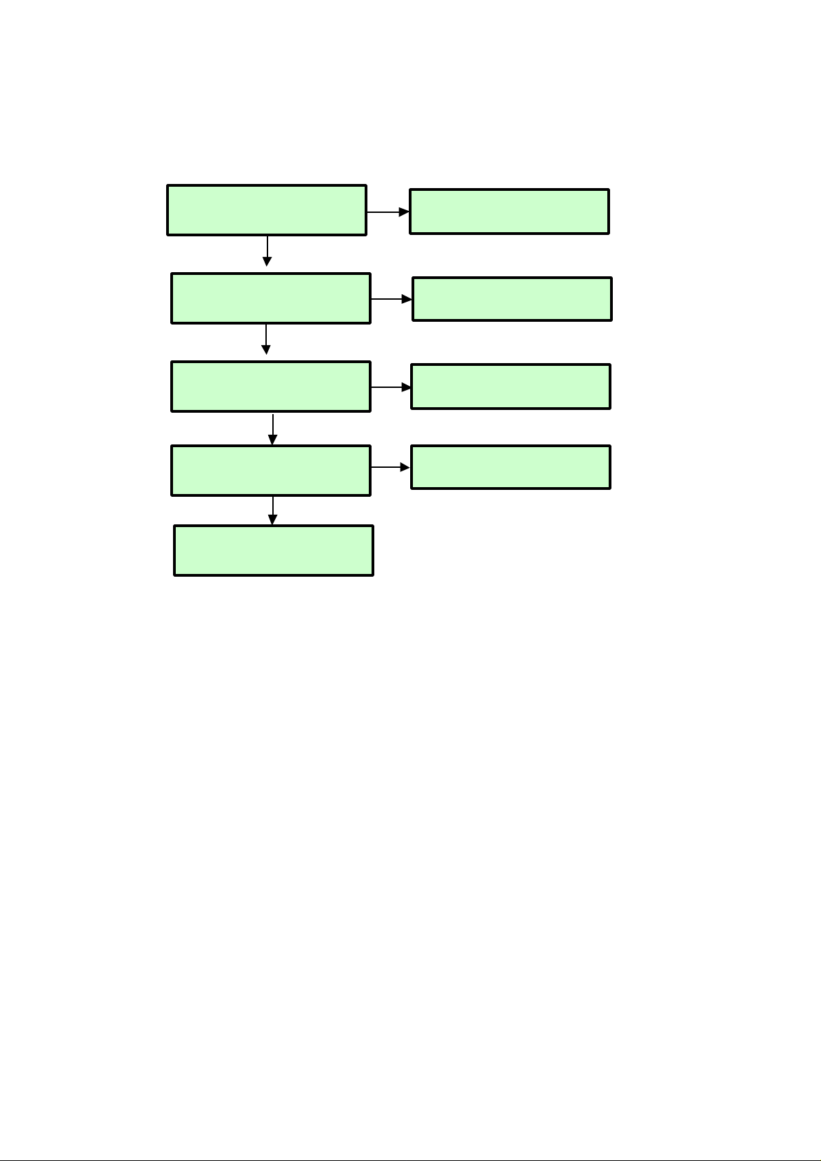
USB Trouble Shooting
Check USB 2.0 Cable
Check L205 voltage level 5V
Y
N
Replace it or IC202
Check JK201
Replace it
Y
N
Check USB Device
If device is 2.5 inch HDD, check power adaptor
Y
Maybe BCM3553 has problems
Y
¥ Exception
- USB power could be disabled by inrushing current
- In this case, remove the device and try to reboot the TV (AC power off/on)
Page 40

- 40 -
Copyright © 2008 LG Electronics. Inc. All right reserved.
Only for training and service purposes
LGE Internal Use Only
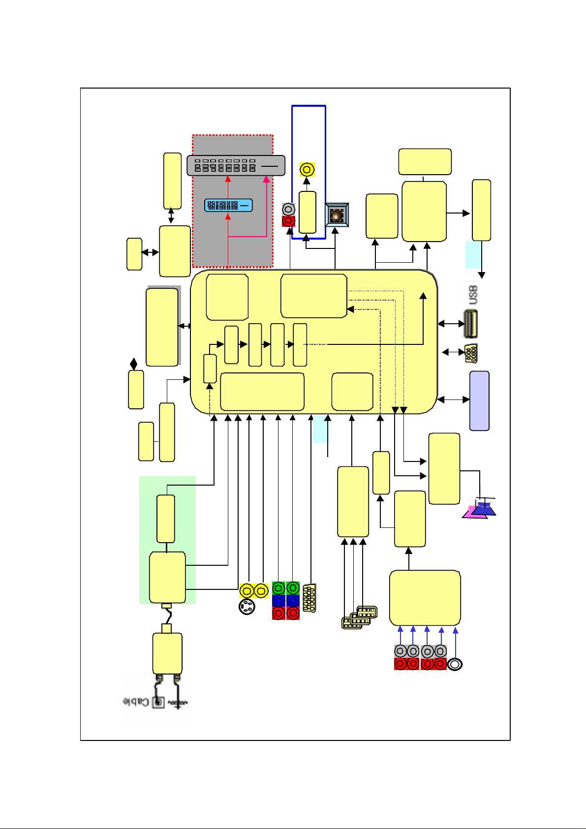
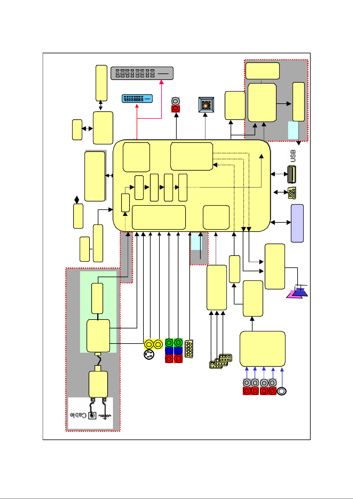
DIAGRAMA DE BLOCOS
Flash
(32MB)
DDR1(128MB)
DDR1(128MB)
(16Mx16x4)
TEA6420
Audio
SW
MTV416
(Micom)
NTP3000A
(Digital AMP)
64Bit I/F
RGB-PC
HDMI
1/2/3
COMP 1
COMP 2
AV1
AV2
RGB-PC
I2S
MCLK
Digital out
COMP1
COMP2
AV1
AV2
BCM7412
(MPEG4
Decoder)
Analog
/Digital
Tuner
TC90512
DVI
I2S
SIF
SPDIF Out
CVBS
CVBS
Y/Cb/Cr
R/G/B
DDR1
(32MB)
CS5340
L/R
Serial TP
30bits
20bit YCbCr 4:2:2
NIM TUNER
TMDS_RX+-
EPM240F
MNT out (Audio Only)
TMDS351
(3x1,S/W)
CVBS/Y/C
MC33078
(AMP)
L/R
RS232
RX/TX
DVI
4:4:4 30bit YCbCr
Full HD(1080P)
WXGA(768P)
RF
Switch
DM1/DP1
Serial
TP
74HC04
SPDIF Out
(Coaxial)
Video
Front
End
Dual
HDMI
Rx
HD/SD
Video
Encoder
Audio
DSP
USB2.0
PKT
HSX
PCI/
EBI
HD-DVI
IB0
Parse2
RSBUF
XCBUF
RMX0
BCM3553
Local KEY
24C16
74LVC14APW
X-tal(54M)
Reset
KIA7029
NVRAM
I2C
LCD Only
Page 41

- 41 -
MEMO
Copyright © 2008 LG Electronics. Inc. All right reserved.
Only for training and service purposes
LGE Internal Use Only
Page 42

- 42 -
Copyright © 2008 LG Electronics. Inc. All right reserved.
Only for training and service purposes
LGE Internal Use Only
VISTAS EXPLODIDAS
603
602
601
520
400
590
501
307
120
121
306
560
570
571
310
302
303
305
300
304
200
250
901900
240
209
208
201
204
207
A2
A21
205
206
580
202
203
301
401
Many electrical and mechanical parts in this chassis have special safety-related characteristics. These
parts are identified by in the Schematic Diagram and EXPLODED VIEW.
It is essential that these special safety parts should be replaced with the same components as
recommended in this manual to prevent X-RADIATION, Shock, Fire, or other Hazards.
Do not modify the original design without permission of manufacturer.
IMPORTANT SAFETY NOTICE
Page 43

Copyright©2008 LG Electronics. Inc. All right reserved.
Only for training and service purposes
LGE Internal Use Only
Page 44

Copyright©2008 LG Electronics. Inc. All right reserved.
Only for training and service purposes
LGE Internal Use Only
Page 45

Copyright©2008 LG Electronics. Inc. All right reserved.
Only for training and service purposes
LGE Internal Use Only
Page 46

Copyright©2008 LG Electronics. Inc. All right reserved.
Only for training and service purposes
LGE Internal Use Only
MAIN(TOP) MAIN(BOTTOM)
PRE-AMP(TOP)
CONTROL(TOP)
CONTROL(BOTTOM)
PRE-AMP(BOTTOM)
Page 47

Depto de Assistência Técnica
Av. D. Pedro I, W7777 - Distrito Industrial
Piracangagua II - Taubaté - SP - Brasil
Cx. Postal 324 - CEP 12.010-970
Tel. : (012) 221-8555 Fax. : (012)221-8550
Jan., 2008
Printed in KoreaP/NO : MFL42027405
LG Electronics Inc.
 Loading...