

LG 50PG6010-ZE Schematic

PLASMA TV
SERVICE MANUAL
CAUTION
BEFORE SERVICING THE CHASSIS,
READ THE SAFETY PRECAUTIONS IN THIS MANUAL.
CHASSIS : PD81A
MODEL : 50PG6010 50PG6010-ZE
website:http://biz.LGservice.com
Internal Use Only

- 2 -
LGE Internal Use OnlyCopyright©2008 LG Electronics. Inc. All right reserved.
Only for training and service purposes
CONTENTS
CONTENTS .............................................................................................. 2
SAFETY PRECAUTIONS ..........................................................................3
SPECIFICATION ........................................................................................4
ADJUSTMENT INSTRUCTION .................................................................6
TROUBLE SHOOTING ............................................................................11
BLOCK DIAGRAM...................................................................................20
EXPLODED VIEW .................................................................................. 30
SVC. SHEET ...............................................................................................
PRINTED CIRCUIT DIAGRAM ....................................................................
- 3 -
LGE Internal Use OnlyCopyright©2008 LG Electronics. Inc. All right reserved.
Only for training and service purposes
SAFETY PRECAUTIONS
Many electrical and mechanical parts in this chassis have special safety-related characteristics. These parts are identified by in the
Schematic Diagram and Replacement Parts List.
It is essential that these special safety parts should be replaced with the same components as recommended in this manual to prevent
X-RADIATION, Shock, Fire, or other Hazards.
Do not modify the original design without permission of manufacturer.
General Guidance
An isolation Transformer should always be used during the
servicing of a receiver whose chassis is not isolated from the AC
power line. Use a transformer of adequate power rating as this
protects the technician from accidents resulting in personal injury
from electrical shocks.
It will also protect the receiver and it's components from being
damaged by accidental shorts of the circuitry that may be
inadvertently introduced during the service operation.
If any fuse (or Fusible Resistor) in this monitor is blown, replace it
with the specified.
When replacing a high wattage resistor (Oxide Metal Film Resistor,
over 1W), keep the resistor 10mm away from PCB.
Keep wires away from high voltage or high temperature parts.
Due to high vacuum and large surface area of picture tube,
extreme care should be used in handling the Picture Tube.
Do not lift the Picture tube by it's Neck.
Leakage Current Cold Check(Antenna Cold Check)
With the instrument AC plug removed from AC source, connect an
electrical jumper across the two AC plug prongs. Place the AC
switch in the on position, connect one lead of ohm-meter to the AC
plug prongs tied together and touch other ohm-meter lead in turn to
each exposed metallic parts such as antenna terminals, phone
jacks, etc.
If the exposed metallic part has a return path to the chassis, the
measured resistance should be between 1MΩ and 5.2MΩ.
When the exposed metal has no return path to the chassis the
reading must be infinite.
An other abnormality exists that must be corrected before the
receiver is returned to the customer.
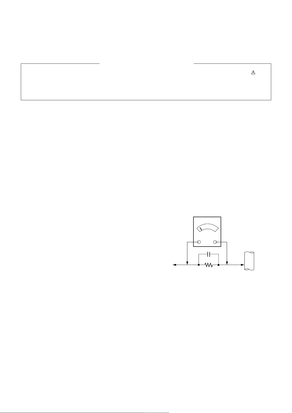
Leakage Current Hot Check (See below Figure)
Plug the AC cord directly into the AC outlet.
Do not use a line Isolation Transformer during this check.
Connect 1.5K/10watt resistor in parallel with a 0.15uF capacitor
between a known good earth ground (Water Pipe, Conduit, etc.)
and the exposed metallic parts.
Measure the AC voltage across the resistor using AC voltmeter
with 1000 ohms/volt or more sensitivity.
Reverse plug the AC cord into the AC outlet and repeat AC voltage
measurements for each exposed metallic part. Any voltage
measured must not exceed 0.75 volt RMS which is corresponds to
0.5mA.
In case any measurement is out of the limits specified, there is
possibility of shock hazard and the set must be checked and
repaired before it is returned to the customer.
Leakage Current Hot Check circuit
1.5 Kohm/10W
To Instrument's
exposed
METALLIC PARTS
Good Earth Ground
such as WATER PIPE,
CONDUIT etc.
AC Volt-meter
IMPORTANT SAFETY NOTICE
0.15uF
- 4 -
LGE Internal Use OnlyCopyright©2008 LG Electronics. Inc. All right reserved.
Only for training and service purposes
SPECIFICATIONS
NOTE : Specifications and others are subject to change without notice for improvement
.
V Application Range
This spec is applied to the 50” PLASMA TV used PD81A Chassis.
V Specification
Each part is tested as below without special appointment.
1) Temperature : 25±5°C (77±9°F), CST : 40±5
2) Relative Humidity: 65±10%
3) Power Voltage: Standard Input voltage (100-240V~, 50/60Hz)
* Standard Voltage of each product is marked by models.
4) Specification and performance of each parts are followed each drawing and specification by part number in accordance with SBOM.
5) The receiver must be operated for about 20 minutes prior to the adjustment.
V Test Method
1) Performance : LGE TV test method followed.
2) Demanded other specification
Safety : CB specification
EMC : CISPR 13 specification
V General Specification1 ( 50” WXGA Module)
Display Screen Device
Aspect Ratio
PDP Module
Operating Environment
Storage Environment
Input Voltage
1
2
3
4
5
6
No Item Specification Remark
50” Wide Color Display Module
16:9
PDP50G1,
RGB Closed(Well) Type, Glass Filter(38%)
Pixel Format : 1365horiz. By 768 ver.l
1)Temp. : 0~40deg
2)Humidity : 20~80%
3)Temp. : -20~60deg
4)Humidity : 10~90%
100-240V~, 50/60Hz
Plasma Display Panel
LGE SPEC.
Maker : LG
Chassis
PD81A 50PG6010 Austria,Belgium,Bulgaria,Coratia,Czech,Denmark,Finland,
France,Germany,Greece,Hungary,Italy,Luxembourg,
Netherlands,Norway,Poland,Portugal,Rumania,Russia,Ser
bia,Slovenia,Spain,Sweden,Switzerland,UK
LG
Model Name Market Brand Remark
50PG6010-ZE Safety : IEC/EN60065
EMI : EN55013
EMS : EN55020
Austria,Belgium,Bulgaria,Coratia,Czech,Denmark,Finlan
d,France,Germany,Greece,Hungary,Italy,Luxembourg,
Netherlands,Norway,Poland,Portugal,Rumania,Russia,
Serbia,Slovenia,Spain,Sweden,Switzerland,UK
Model ApplianceMarket Remark

- 5 -
LGE Internal Use OnlyCopyright©2008 LG Electronics. Inc. All right reserved.
Only for training and service purposes
V Module Specification
V General Specification2 ( 50” FHD Module )
Market
roadcasting system
Receiving system
Scart Jack(2EA)
Video Input (1EA)
S-Video Input (1EA)
Component Input (1EA)
RGB Input
HDMI Input(4EA)
Audio Input (3EA)
SPDIF Out(1EA)
USB
1
2
3
4
5
6
7
8
9
10
11
12
No Item Specification Remark
Austria,Belgium,Bulgaria,Coratia,Czech,Denmark,Finland
,France,Germany,Greece,Hungary,Italy,Luxembourg,
Netherlands,Norway,Poland,Portugal,Rumania,Russia,
Serbia,Slovenia,Spain,Sweden,Switzerland,UK
1) PAL/SECAM BG
2) PAL/SECAM DK
3) PAL I / II
4) SECAM L/L’
5) DVB T
Analog : Upper Heterodyne
Digital : COFDM
PAL, SECAM
PAL, SECAM, NTSC
PAL, SECAM, NTSC
Y/Cb/Cr, Y/Pb/Pr
RGB-PC
HDMI-PC
HDMI-DTV
RGB/DVI Audio, Component, AV
SPDIF OUT
For SVC, S/W Download, X-Studio
25 Country
EU(PAL Marker)
Scart1 Jack is Full scart and support
RF-OUT(Analoge)
Scart2 Jack is Half scart and support
MNT-OUT
Analog(D-Sub 15Pin)
HDMI1/DVI,HDMI2,HDMI3,HDMI4
L/R Input
Side(X-Studio Only PG60 Series)
Display Screen Device
Aspect Ratio
PDP Module
Operating Environment
Storage Environment
Input Voltage
1
2
3
4
5
6
No Item Specification Remark
50” Wide Color Display Module
16:9
PDP50G1,
RGB Closed(Well) Type, Glass Filter(38%)
Pixel Format : 1365horiz. By 768 ver.
1)Temp. : 0~40deg
2)Humidity : 20~80%
3)Temp. : -20~60deg
4)Humidity : 10~90%
100-240V~, 50/60Hz
Plasma Display Panel
LGE SPEC.
Maker : LG
- 6 -
LGE Internal Use OnlyCopyright©2008 LG Electronics. Inc. All right reserved.
Only for training and service purposes
ADJUSTMENT INSTRUCTION
1. Application Object
These instructions are applied all of the 50” PLASMA TV,
PD81A Chassis.
2. Note
(1) Because this is not a hot chassis, it is not necessary to use
an isolation transformer. However, the use of isolation
transformer will help protect test instrument.
(2) Adjustment must be done in the correct order.
(3) The adjustment must be performed in the circumstance of
25±5°C of temperature and 65±10% of relative humidity if
there is no specific designation.
(4) The input voltage of the receiver must keep 100-240V~,
50/60Hz.
(5) The receiver must be operated for about 15 minutes prior
to the adjustment.
O After RGB Full white HEAT-RUN Mode, the receiver must
be operated prior to adjustment.
O Enter into HEAT-RUN MODE
1) Press the POWER ON KEY on R/C for adjustment.
2) OSD display and screen display PATTERN MODE.
- Select “3. Test Pattern” by using
D/E(CH+/-) and
press ENTER(
V)
- Select “White” by using (
F/GVOL+/-) and press
ENTER(
V)
* Set is activated HEAT-RUN without signal generator in
this mode.
* Single color pattern(RED/BLUE/GREEN) of HEAT-RUN
mode uses to check PANEL.
3.
S/W auto download using the USB
Memory stick
(1) Insert the USB memory sick the PCB ASSEMBLY.
(2) Using ‘power on’ button of the control R/C, power on TV.
(3) S/W download process is executed automatically.
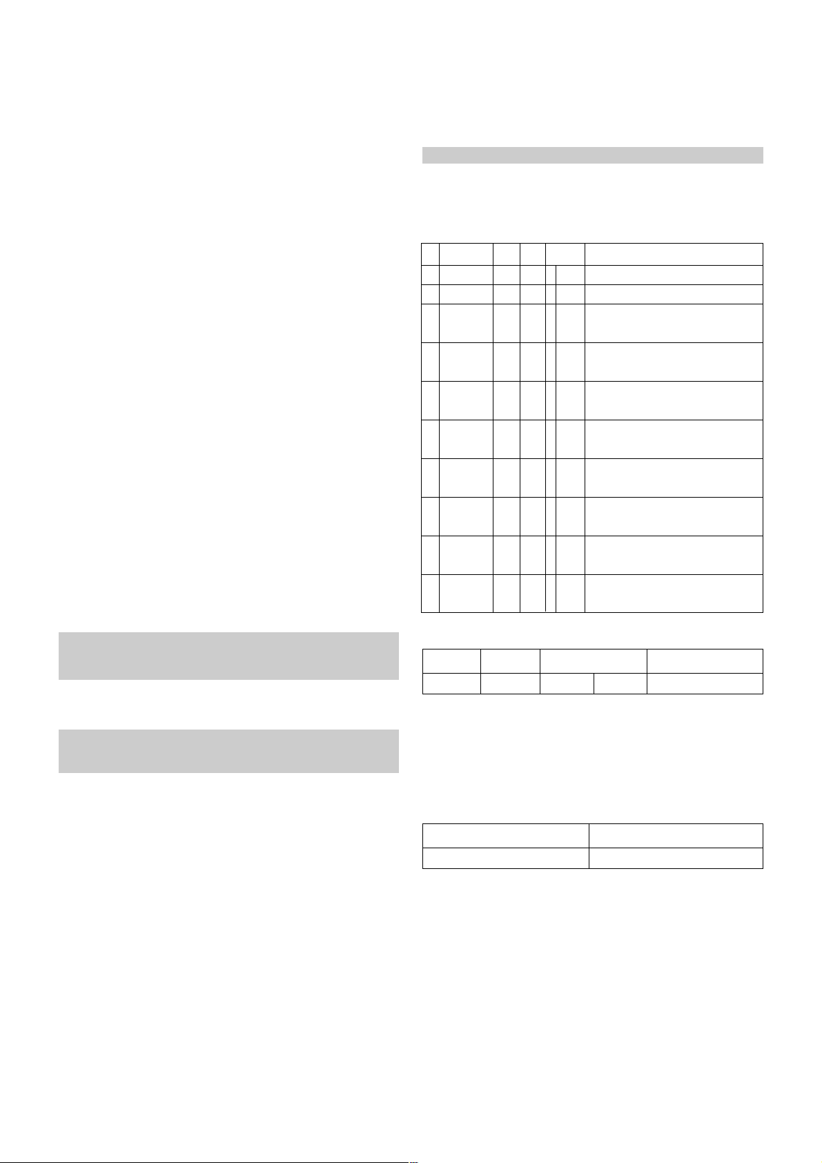
4.
Auto-control adjustment process
V
All adjustment process is executed one time through RS-232C.
V Command send -> ADC Calibration -> Model name
download -> EDID download.
V Adjsutment process protocol(RS-232C)
5. Manual model name download
(1) Press ADJ KEY on R/C for model name D/L.
(2) Select “0.Model Option” and press ENTER(
V).
(3) Select model name by using
D/E (CH+/-)and press
ENTER(
V).
* Using ‘power on’ button off the control R/C, power on TV.
All adjustment process is executed one time through RS-232C.
Do not connect extrenal input calbe.
* Using ‘power on’ button of the control R/C, power on TV.
USB file(EPK) version must be bigger than downloaded
version of main B/D.
* Using ‘power on’ button off the control R/C, power on TV.
1
2
3
4
5
6
7
8
9
10
Ready
ADC
ADC
Confirmation
ADC
Mode Out
Download
Mode In
EDID
Download
Check EDID
Status
Define model
name
Adjustment
Confirmation
Download
Mode Out
NO
Item
Remark
CMD1 CMD2
Data 0
a
a
a
a
a
a
a
a
a
a
d
d
d
d
e
e
e
e
e
e
0
0
9
0
0
0~4,9
0~4,9
1~7
9
0
0
1
9
9
0
1
2
5
9
9
Ready
ADC start
Transmitting adjustment mode In
instruction, operate adjustment command.
All=0 ; HDMI1,2,3,4=1,2,3,4 ; RGB=9
All=0 ; HDMI1,2,3,4=1,2,3,4 ; RGB=9
Model define index(Data0) are listed at
next table.
EDID data existence check in SET
assembly
ae55
50PG6010-ZE
CMD1 CMD2 Data 0 Remark
50PG6010-ZE
37000001
Model Name Model Option Value
- 7 -
LGE Internal Use OnlyCopyright©2008 LG Electronics. Inc. All right reserved.
Only for training and service purposes
6. Manual
ADC Adjustment
V Adjustment is done using internal ADC, so input signal is
not necessary.
V Do not connect external input cable.
6-1. Required Equipment
(1) Press ADJ KEY on R/C and enter EZ ADJUST.
(2) Select “1.EDID D/L” by using
D/ E(CH+/-) and press
ENTER(
V).
(3) Select “Start” by using
F/G(VOL+/-) and press ENTER(V).
(4) ADC Adjustment is executed automatically.
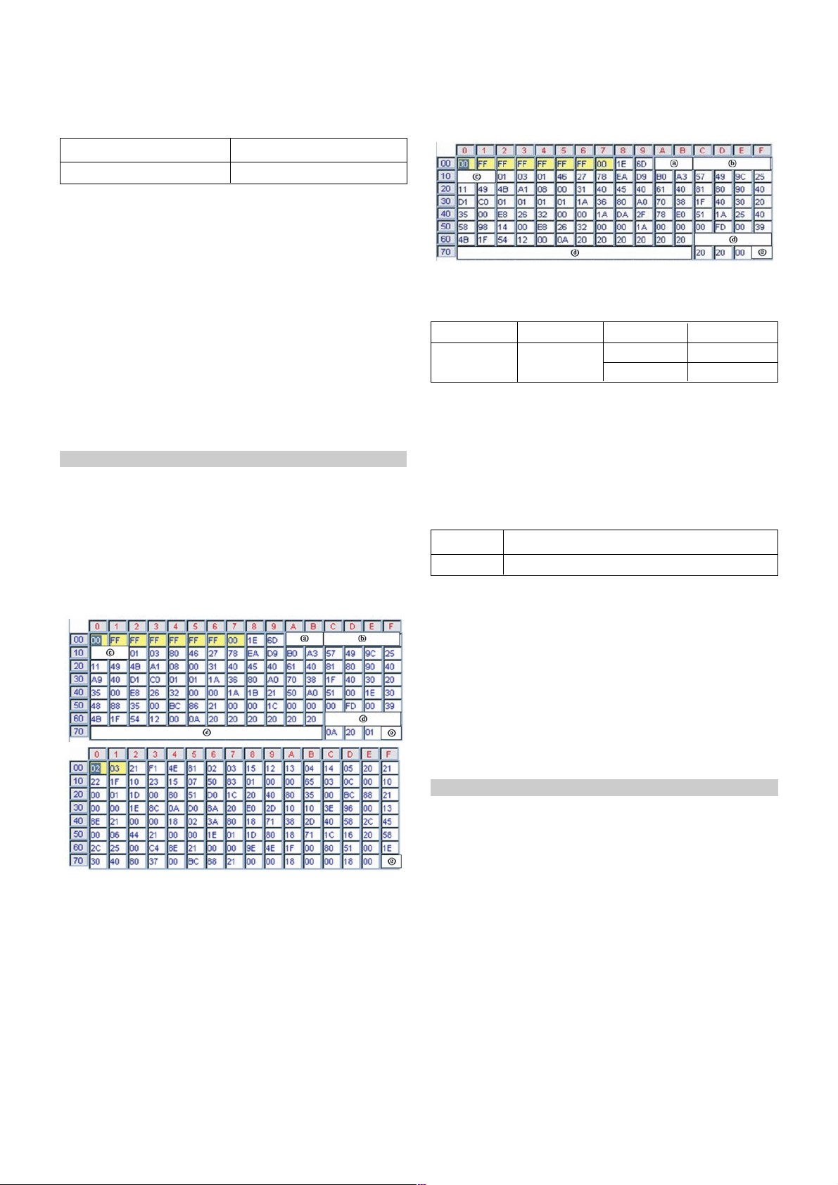
7. EDID Download
7-1. Required Equipment
(1) Press ADJ KEY on R/C and enter EZ ADJUST.
(2) Select “5.EDID D/L” by using
D/E(CH+/-) and press
ENTER(
V).
(3) Select “Start” and press ENTER(
V).
(4) EDID download is executed automatically.
(5) Press EXIT key on R/C.
7-2.
EDID DATA
(1) HDMI1(256bytes)
(2) RGB(128bytes)
-> Detail EDID Options are below (ⓐ, ⓑ, ⓒ, ⓓ, ⓔ)
ⓐ Product ID
ⓑ Serial No
=> Controlled on production line
ⓒ Month, Year
=> Controlled on production line:
ex) Monthly: ‘11’ -> ‘0B’
Year: ‘2007’ -> ‘11’
ⓓ Model Name(Hex)
ⓔ Checksum
=> Changeable by total EDID data.
8. PCMCIA CARD Checking Method
: You must adjust DTV29 Channel and insert PCMCIA CARD
to socket.
1) If PCMCIA CARD works normally, normal signals display
on screen. But it works abnormally, “No CA module” words
display on screen.
*Do not connect HDMI and RGB cable.
NO SIGNAL or White noise NO SIGNAL
RF Input AV / Component / RGB input
50PG6010-ZE
EDID MODEL Product ID FUCTIONModel Name
Analog
Digital
50138(C3DA)
50139(C3DB)
50PG6010-ZE
50PG6010
00 00 00 FC 00 35 30 50 47 39 30 31 30 0A 20 20 20 20
Model Name Model Name(Hex)
* Set up “RF mode” before launching products.
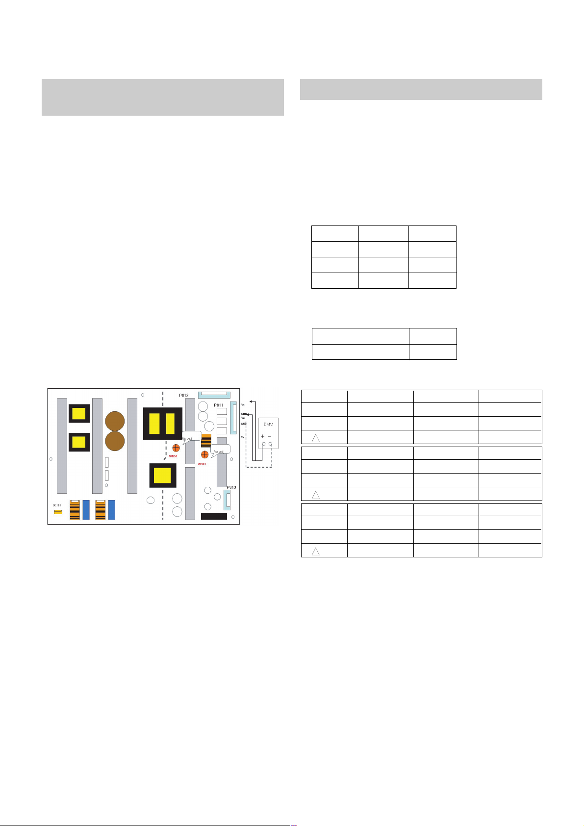
9. POWER PCB Assy Voltage
Adjustments (Va, Vs Voltage adjustments)
9-1. Test Equipment : D.M.M. 1EA
9-2.Connection Diagram for Measuring
: refer to Fig.1
9-3. Adjustment Method
(1) Va Adjustment
1) After receiving 100% Full White Pattern, HEAT RUN.
2) Connect + terminal of D.M.M to Va pin of P811, connect
- terminal to GND pin of P811.
3) After turning VR901, voltage of D.M.M adjustment as
same as Va voltage which on label of panel right/top.
(Deviation; ±0.5V)
(2) Vs Adjustment
1) Connect + terminal of D.M.M to Vs pin of P811, connect
– terminal to GND pin of P811.
2) After turning VR951, voltage of D.M.M adjustment as
same as Va voltage which on label of panel right/top.
(Deviation; ±0.5V)
10. Adjustment of White Balance
10-1. Required Equipment
(1) Color Analyzer : CS-100, CA-100+(CH.10), CA-
210(CH.10))
* Please adjust CA-100+/CA-210 by CS-1000 before
measuring.
-> You should use Channel 10 which is Matrix
compensated.
N Color temperature standards according to CSM and Module.
N Change target luminance and range of the Auto adjustment
W/B equipment.
N White balance adjustment coordinate and color temperature.
- 8 -
LGE Internal Use OnlyCopyright©2008 LG Electronics. Inc. All right reserved.
Only for training and service purposes
Each PCB assembly must be checked by check JIG set.
(Because power PCB Assembly damages to PDP Module,
especially be careful)
(Fig.1) Connection diagram of power adjustment for measuring
* Before adjusting White-balance, the AV ADC should be done.
If ADC status were “NG”, Need to ADC adjustment.
PLASMA Remark
11000K
9300K
6500K
Cool
Normal
Warm
CSM
65
20Range
Target luminance
0.276
0.283
0.000
0.276±0.002
0.283±0.002
0.000
0.276±0.002
0.283±0.002
0.000
X
y
uv
Cool CS-1000 CA-100+(CH.10) CA-210(CH.10)
0.285
0.293
0.000
0.285±0.002
0.293±0.002
0.000
0.285±0.002
0.293±0.002
0.000
X
y
uv
Medium CS-1000 CA-100+(CH.10) CA-210(CH.10)
0.313
0.329
0.003
0.313±0.002
0.329±0.002
0.003
0.313±0.002
0.329±0.002
0.003
X
y
uv
Warm CS-1000 CA-100+(CH.10) CA-210(CH.10)
10-2. Connection Picture of the Measuring
Instrument(On Automatic control)
(1) Inside PATTERN is used when W/B is controlled. Connect
to auto controller or push control R/C IN-START -> Enter
the mode of White-Balance, the pattern will come out.
10-3. Auto-control interface and directions
(1) Adjust in the place where the influx of light like floodlight
around is blocked.(illumination is less than 10ux)
(2) Measure and adjust after sticking the Color Analyzer(CA-
100+, CA210) to the side of the module.
(3) Aging time
- After aging start, keep the power on(no suspension of
power supply) and heat-run over 15 minutes.
- keep white pattern using inside pattern.
A Auto adjustment Map(RS-232C)
11. Adjustment of White Balance
(1) Press ADJ KEY on R/C and enter EZ ADJUST.
Select “3. Test Pattern” by using
D/E(CH+/-) and press
ENTER(
V)
Select “White” by using
F/G(VOL+/-) and press ENTER(V)
and heat run over 15minutes.
(2) Zero Calibrate CA-100+/CA-210, and when controlling,
stick the sensor to the center of PDP module.
(3) Press ADJ KEY on R/C and enter EZ ADJUST.
Select “2. White Balance” and press
G(VOL +).
Set test-pattern on and display inside pattern.
(5) Control is carried out on three color temperatures, COOL,
MEDIUM,WARM.
(Control is carried out thress times)
<Temperature : COOL>
- R-Cut / G-Cut / B-Cut is set to 64/
- Control R-Gain and G-Gain.
- Each Gain is limited to 192.
<Temperature : MEDIUM>
- R-Cut / G-Cut / B-Cut is set to 64/
- Control R-Gain and G-Gain.
- Each Gain is limited to 192.
<Temperature : WARM>
- R-Cut / G-Cut / B-Cut is set to 64/
- Control G-Gain and B-Gain.
- Each Gain is limited to 192.
12. Input the Shipping Option Data
1) Push the IN-START key in a Adjust Remocon.
2) Input the Option Number that was specified in the BOM, into
the Shipping area.
3) The work is finished, Push
V Key.
13. Set Information
(Serial No& Model name)
13-1.
Check the serial number & Model Name
(1) Push the menu button in DTV mode.
(2) Select the SETUP -> Diagnostics -> To set.
(3) Check the Serial Number.
- 9 -
LGE Internal Use OnlyCopyright©2008 LG Electronics. Inc. All right reserved.
Only for training and service purposes
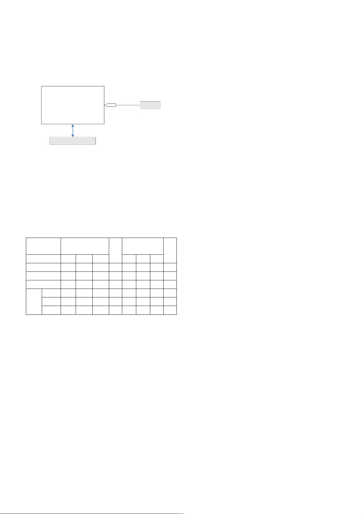
(Fig.6) Auto AV(CVBS) Color Balance Test Pattern
Full White Pattern
RS-232C Communication
CA-210
Color
ANALYZER
TYPE : CA-210
R Gain
G Gain
B Gain
R Offset
G Offset
B Offset
Cool Med Warm Cool Med Warm
jg Ja js 00 192 192 192 255
jh Jb je 00 192 192 192 255
ji Jc jf 00 192 192 192 255
62 63 66 128
58 57 62 128
71 71 64 128
RS-232C COMMAND
[CMD ID DATA]
Min
CENTER
(DEFAULT)
MAX
50PG1
14. SET factoring condition
(1) This adjustment is setting factory shipment mode.
(2) Push the IN-STOP key of adjustment remote controller before
the factory shipment.
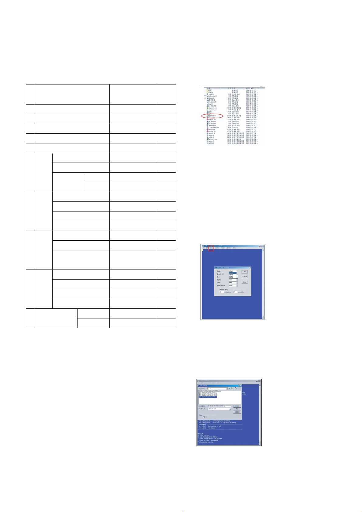
15. Flash Memory Download
15-1. Configuration Environment
(1) To installation the ‘LG Term’, extract ‘lgterm.zip’ to a folder.
(2) Execute ‘lgterm.exe’.
(3) Before downloading epk file, change the baud-rate value.
1) Press the ‘IN-START’ button.
2) Select the ‘System’ menu.
3) Enter ‘115200bps’ on the ‘Baudrate’.
4) Exit the menu.
15-2. Download epk file using ‘LG Term’
(1) Execute ‘lgterm.exe’
(2) Select a serial port and change a baud-rate value.
1) Select a serial port which is connected through a RS232 cable on ‘Setup’ Menu.
* If the selected port is not connected, a warning message
will appear.
2) Change the baud-rate from a default value to
‘115200bps’ on ‘Setup’ Menu.
(3) Press the OK button.
(4) Turn on the TV set and press the ‘Enter’ key at the same
time.
(5) Douglas prompt will appear.
(6) Insert ‘swuhz’ and enter.
(7) Change the baud-rate to ‘460800bps’ on ‘Setup’ Menu.
(8) Press ‘Alt+F’, ‘T’, ‘Z’, ‘S’ in order.
(9) Select the epk file.
(10) It will take 4~5 minutes.
(11) To apply last epk file, TV set should be restarted.
- 10 -
LGE Internal Use OnlyCopyright©2008 LG Electronics. Inc. All right reserved.
Only for training and service purposes
1
2
3
4
5
6
7
8
9
10
Antenna
10
Off
16:9
1
Vivid
Medium
Off
Auto
Standard
Off
0
On
On
--
Off
On
Off
Normal
Off
Item ConditionNo
Remark
Input Mode
Volume Level
Mute
Aspect Ratio
SET ID
Picture PSM
Color Temp.
Advanced Cinema
Black level
Sound SSM
AVL
Balance
TV Speaker
Time Auto Clock
Manual Clock
Off Timer / On Timer
Sleep Timer / Auto Off
Option SIMPLINK
Key Lock
ISM Method
Power Saving
Channel Memory Analog
Digital
- 11 -
LGE Internal Use OnlyCopyright©2008 LG Electronics. Inc. All right reserved.
Only for training and service purposes
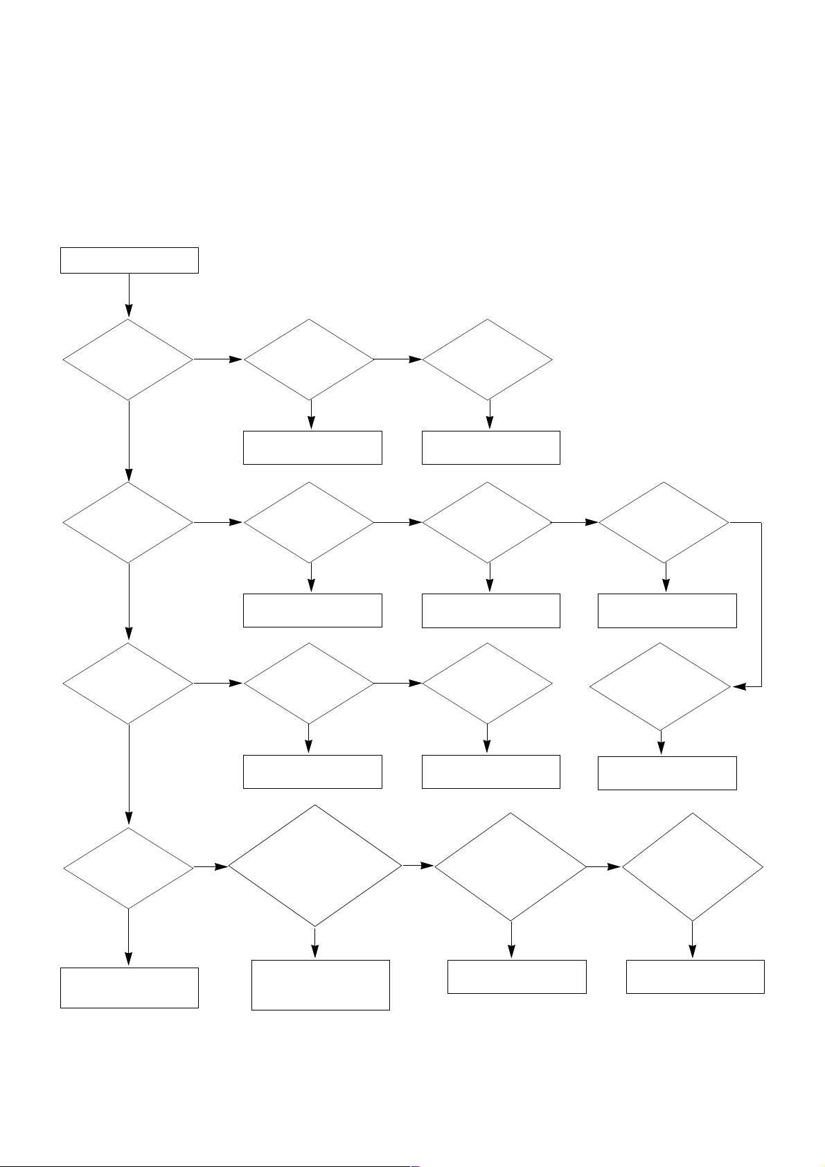
TROUBLE SHOOTING GUIDE
1. Power Board
1-1. The whole flowchart which it follows in voltage output state
Start check
Manufacture enterprise
meaning of a passage
1. Check the Power Off
condition.
Doesn't the
screen whole come
out?
Is it identical
with Power Off
condition?
Yes
Yes
No
No
No
No
No
2. Check the Interface
signal condition.
Is the Interface
signal operated?
Yes
3. Check the St-by 5V
signal circuit.
Doesn't the
low pressure output
come out?
Doesn't the
St-by 5V signal
come out?
Yes
Yes
No
4. Check the 5V Monitor
signal circuit.
Doesn't the
5V Monitor signal
come out?
Yes
7. Check the VSC Vs-ON
signal
Doesn't the
high tension output
come out?
Doesn't the
VSC signal Vs-ON
come out?
Yes
Yes
Does
high tension
output voltage Drop
occur?
When the
Y B/D Module
input connector is
removed, does output
voltage drop
occur?
When the
Y, Z B/D Module
input connector is remove,
does Power Board hightension
output voltage Drop
occur?
Yes No No
9. Check the Power
Board Output high
tension circuit
Yes
10. Check the Z B/D
Module output circuit
Yes
When the
Z B/D Module
input connector is
removed, does output
voltage Drop
occurs?
11. Check the Y B/D
Module output circuit
Yes
No
8. Check the Vs, Va
voltage output circuit.
Doesn't the
Vs, Va voltage output
come out?
Yes
No
No
5. Check the VSC RL-ON
signal.
Doesn't the
VSC signal RL-ON
come out?
Yes
6. Check the VSC low
pressure output
Doesn't the
VSC low pressure
output come out?
Yes
 Loading...