

Page 1

PLASMA TV
SERVICE MANUAL
CAUTION
BEFORE SERVICING THE CHASSIS,
READ THE SAFETY PRECAUTIONS IN THIS MANUAL.
CHASSIS : PD61A
MODEL : 50PC1DA 50PC1DA-EC
website:http://biz.LGservice.com
Page 2

- 2 -
CONTENTS
SAFETY PRECAUTIONS ....................................................................................3
DESCRIPTION OF CONTROLS ..........................................................................4
SPECIFICATIONS ................................................................................................9
ADJUSTMENT INSTRUCTIONS .......................................................................11
TROUBLE SHOOTING GUIDE..........................................................................17
BLOCK DIAGRAM.............................................................................................22
EXPLODED VIEW..............................................................................................24
EXPLODED VIEW PARTS LIST ........................................................................25
REPLACEMENT PARTS LIST...........................................................................26
SCHEMATIC DIAGRAM.........................................................................................
PRINTED CIRCUIT DIAGRAM ..............................................................................
Page 3
- 3 -
SAFETY PRECAUTIONS
Many electrical and mechanical parts in this chassis have special safety-related characteristics. These parts are identified by in the
Schematic Diagram and Replacement Parts List.
It is essential that these special safety parts should be replaced with the same components as recommended in this manual to prevent
X-RADIATION, Shock, Fire, or other Hazards.
Do not modify the original design without permission of manufacturer.
General Guidance
An isolation Transformer should always be used during the
servicing of a receiver whose chassis is not isolated from the AC
power line. Use a transformer of adequate power rating as this
protects the technician from accidents resulting in personal injury
from electrical shocks.
It will also protect the receiver and it's components from being
damaged by accidental shorts of the circuitry that may be
inadvertently introduced during the service operation.
If any fuse (or Fusible Resistor) in this monitor is blown, replace it
with the specified.
When replacing a high wattage resistor (Oxide Metal Film Resistor,
over 1W), keep the resistor 10mm away from PCB.
Keep wires away from high voltage or high temperature parts.
Due to high vacuum and large surface area of picture tube,
extreme care should be used in handling the Picture Tube.
Do not lift the Picture tube by it's Neck.
Leakage Current Cold Check(Antenna Cold Check)
With the instrument AC plug removed from AC source, connect an
electrical jumper across the two AC plug prongs. Place the AC
switch in the on position, connect one lead of ohm-meter to the AC
plug prongs tied together and touch other ohm-meter lead in turn to
each exposed metallic parts such as antenna terminals, phone
jacks, etc.
If the exposed metallic part has a return path to the chassis, the
measured resistance should be between 1MΩ and 5.2MΩ.
When the exposed metal has no return path to the chassis the
reading must be infinite.
An other abnormality exists that must be corrected before the
receiver is returned to the customer.
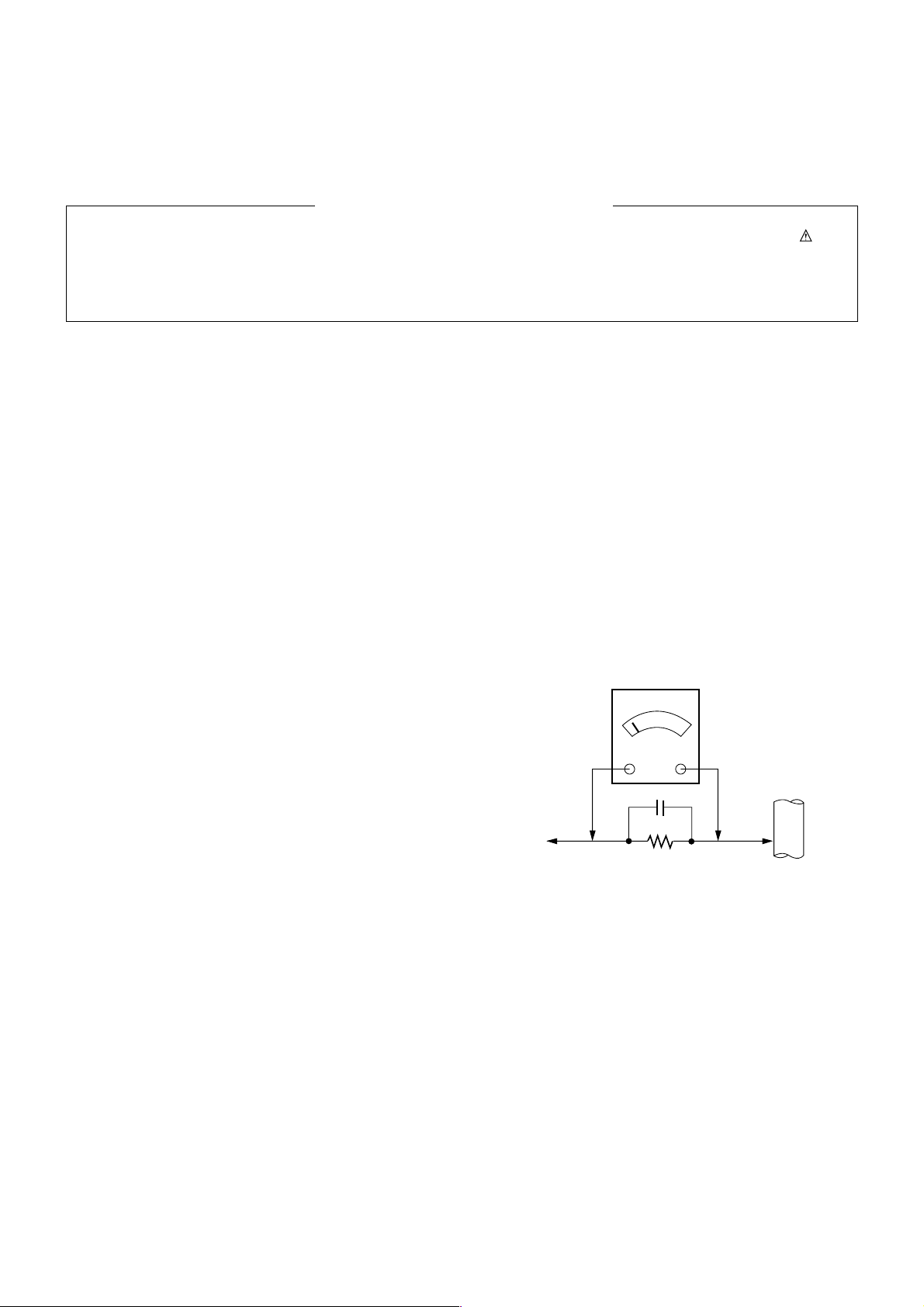
Leakage Current Hot Check (See below Figure)
Plug the AC cord directly into the AC outlet.
Do not use a line Isolation Transformer during this check.
Connect 1.5K/10watt resistor in parallel with a 0.15uF capacitor
between a known good earth ground (Water Pipe, Conduit, etc.)
and the exposed metallic parts.
Measure the AC voltage across the resistor using AC voltmeter
with 1000 ohms/volt or more sensitivity.
Reverse plug the AC cord into the AC outlet and repeat AC voltage
measurements for each exposed metallic part. Any voltage
measured must not exceed 0.75 volt RMS which is corresponds to
0.5mA.
In case any measurement is out of the limits specified, there is
possibility of shock hazard and the set must be checked and
repaired before it is returned to the customer.
Leakage Current Hot Check circuit
1.5 Kohm/10W
To Instrument's
exposed
METALLIC PARTS
Good Earth Ground
such as WATER PIPE,
CONDUIT etc.
AC Volt-meter
IMPORTANT SAFETY NOTICE
0.15uF
Page 4

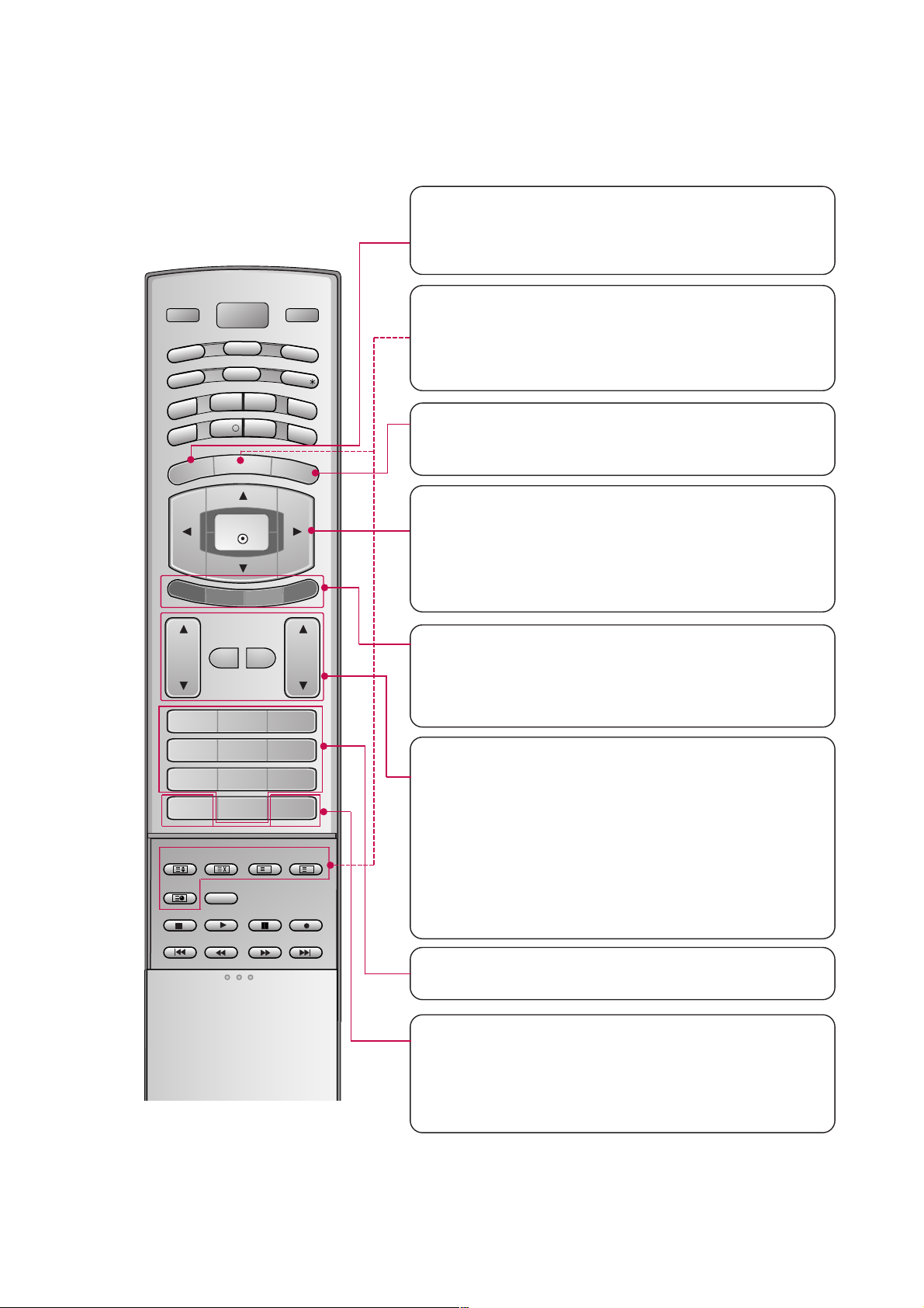
POWER
Switches the set between ON and STANDBY.
D/A TV
INPUT
VOL
LIST
Q.VIEW
PR
POWER
1 2 3
4 5 6
7809
INDEX
POSITION
SIZE
REVEAL
I/II
TIME
GUIDE
PIP PR-
PIP
MENU
MUTE FAV
EXIT
VCR
TV
DVD
ARC
TEXT
SWAP
BACK
PIP PR+
INFO
i
?
i
OK
SUBTITLE/
PIP INPUT
SLEEP
D/A TV (Digital TV / Analogue TV)
Selects digital or analogue mode.
INPUT
Selects the DTV, TV, AV, Component, RGB or HDMI
modes.
switches the set on from standby.
TV, DVD, VCR
Selects the remote operating mode: TV, VCR, DVD.
Select other operating modes, for the remote to operate external devices.
GUIDE
Shows programme schedule.
ARC (Aspect Ratio Control)
Selects your desired picture format.
SUBTITLE/
*
Recalls your preferred subtitle in digital mode.
PIP
Switches the sub picture on or off,select PIP, DW1/2
or POP modes.
SIZE
Adjusts the sub picture size.
POSITION
Moves the sub picture position.
PIP PR +/-
Selects a programme for the sub picture.
SWAP
Alternates between main and sub picture.
PIP INPUT
Selects the input mode for the sub picture.
BACK
Allow the user to move back one step in an interactive application, EPG or other user interaction
function.
SLEEP
Sets the sleep timer.
- 4 -
DESCRIPTION OF CONTROLS
Page 5
- 5 -
MENU
Displays on screen menus one by one.
Exits the current menu.
Memorizes menu changes.
OK
Accepts your selection or displays the current
mode.
DD / EE / FF / GG
Adjusts menu settings.
Selects menu item.
COLOURED BUTTONS
They are used as per the indications or functions displayed on TV screen in case of Text displays
(Teletext, EPG) and programme edit.
VOL
DD / EE
(Volume Up/Down)
Increases/decreases sound level.
PR
DD / EE
(Programme Up/Down)
Selects a programme.
LIST
Displays the programme table.
Q.VIEW
Returns to the previously viewed programme.
NUMBER BUTTONS
MUTE
Switches the sound on or off.
FAV (FAVOURITE)
Displays the selected favourite programmes.
D/A TV
INPUT
VOL
LIST
Q.VIEW
PR
POWER
1 2 3
4 5 6
7809
INDEX
POSITION
SIZE
REVEAL
I/II
TIME
GUIDE
PIP PR-
PIP
MENU
MUTE FAV
EXIT
VCR
TV
DVD
ARC
TEXT
SWAP
BACK
PIP PR+
INFO
i
?
i
OK
SUBTITLE/
PIP INPUT
SLEEP
EXIT
Clears all on-screen displays and returns to TV
viewing from any menu.
TELETEXT BUTTONS
These buttons are used for teletext.
Text button is used to enable teletext services while
other buttons are for teletext functions. * For further
details, see the ‘Teletext’ section.
Page 6

- 6 -
PR
VOL
OK
MENU
INPUT
PROGRAMME Buttons
VOLUME Buttons
MENU Button
OK Button
INPUT Button
POWER Button
Power/Standby
Indicator
• illuminates red in
standby mode.
• illuminates white
when the set is
switched on.
Front Panel Controls
Page 7

- 7 -
AV IN 4V IN 4
L/L/MONOMONO
R
AUDIOAUDIO
VIDEOVIDEO
HDMI INHDMI IN
DIGITDIGITALAL AUDIO AUDIO
OUTOUT
OPTICALPTICAL
1(DVI)1(DVI)
2
RS-232C INRS-232C IN
(CONTROL(CONTROL & SERSERVICE)VICE)
RGB (PCRGB (PC/DTV)DTV)
RGB INRGB IN
AUDIO (RGB/DVI)AUDIO (RGB/DVI)
ININ
OUTOUT
VIDEOVIDEO
AUDIOAUDIO
MONO
( )
VIDEOVIDEO
AUDIOAUDIO
COMPONENT IN
S-VIDEOS-VIDEO
AV IN 3V IN 3
VARIABLEARIABLE
AUDIO OUTAUDIO OUT
REMOTEREMOTE
CONTROLCONTROL
AV 1V 1 AV 2 DTV OUTDTV OUT
ANTENNAANTENNA
IN
ANTENNAANTENNA
OUTOUT
EJECTEJECT PCMCIAPCMCIA SLOT SLOT
AUDIO Input
VIDEO Input
DIGITAL AUDIO OUT
OPTICAL
AV IN 3
VARIABLE AUDIO OUT
AV 1/2
DTV OUT
COMPONENT IN
HDMI/DVI IN
42PC1DV models have
a unit of HDMI / DVI
input jack.
ANTENNA IN
ANTENNA OUT
AUDIO IN
(RGB/DVI)
RGB IN
(PC/DTV)
AC IN
RS-232C INPUT
(CONTROL&SERVICE)
REMOTE CONTROL Port
PCMCIA (Personal
Computer Memory
Card International
Association) Slot
Back Connection Panel
HDMI IN
Page 8
- 8 -
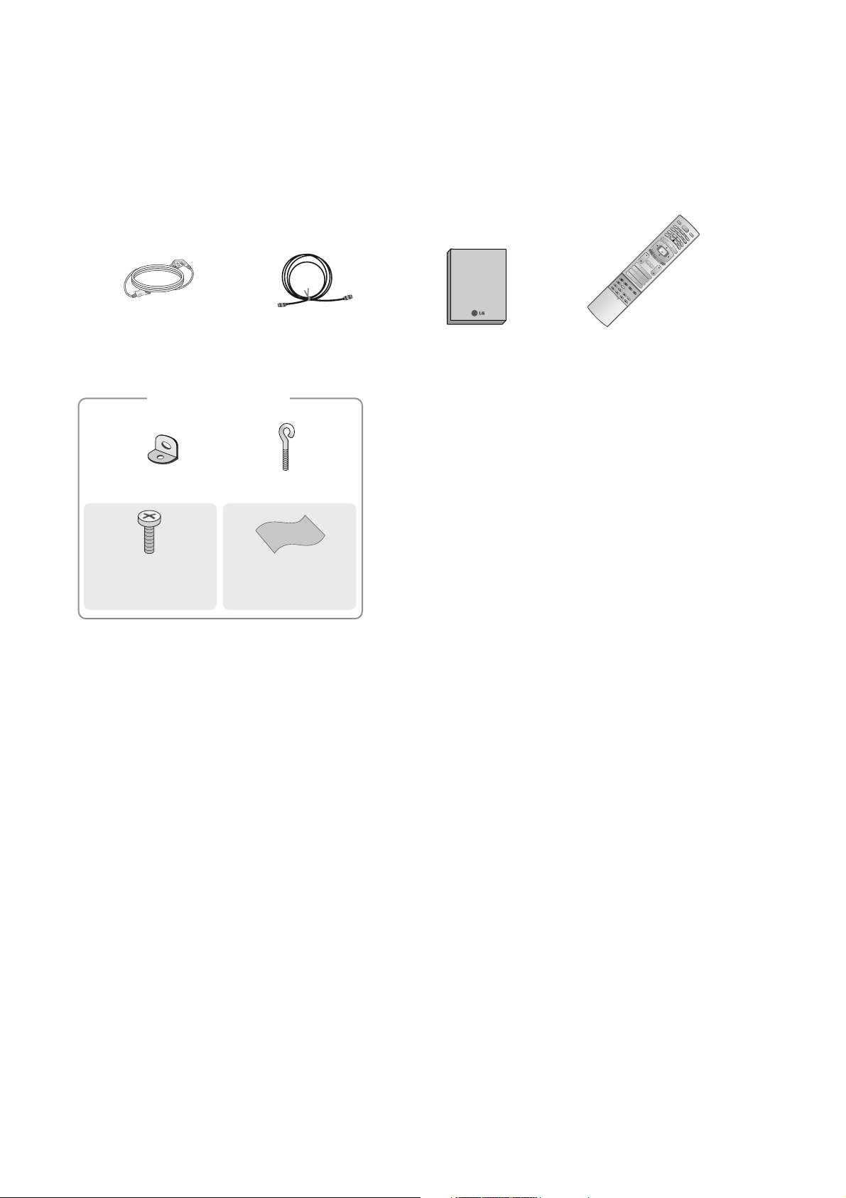
ACCESSORIES
Owner’s Manual
75Ω RF Coaxial
Power Cord
D/A TV
INPUT
VOL
LIST
Q.VIEW
PR
POWER
1 2 3
456
78
0
9
INDEX
POSITION
SIZE
REVEAL
I/II
TIME
G
U
ID
E
P
I
P
P
R
-
P
IP
M
E
N
U
MUTE FAV
E
X
IT
V
C
R
TV
DVD
ARC
TEXT
S
WAP
BAC
K
P
I
P
P
R
+
I
N
F
O
i
?
i
OK
S
U
B
T
I
T
L
E
/
P
IP
IN
P
U
T
S
L
E
E
P
D/A
VOL
LIST
Q.VIEW
PR
1 2 3
456
78
0
9
INDEX
POSITION
SIZE
REVEAL
I/II
TIME
G
U
ID
E
P
I
P
P
R
-
P
IP
M
E
N
U
MUTE FAV
EX
IT
T
V
ARC
TEXT
S
WAP
B
AC
K
P
IP
P
R
+
I
N
F
O
i
?
i
OK
S
L
E
E
P
VOL
LIST
Q.VIE
1 2 3
456
78
0
9
POSITION
SIZE
TIME
MUTE FAV
Remote Control /
Batteries
2-Wall brackets
2-eye-bolts
For 42PC1D*,
42PC3D*, 50PC1D*
Polishing Cloth
(42/50PC1D only)
Polish the screen
with the cloth.
2-bolts
(42PC1D*, 42PC3D*
only)
Owner’s Manual
Page 9

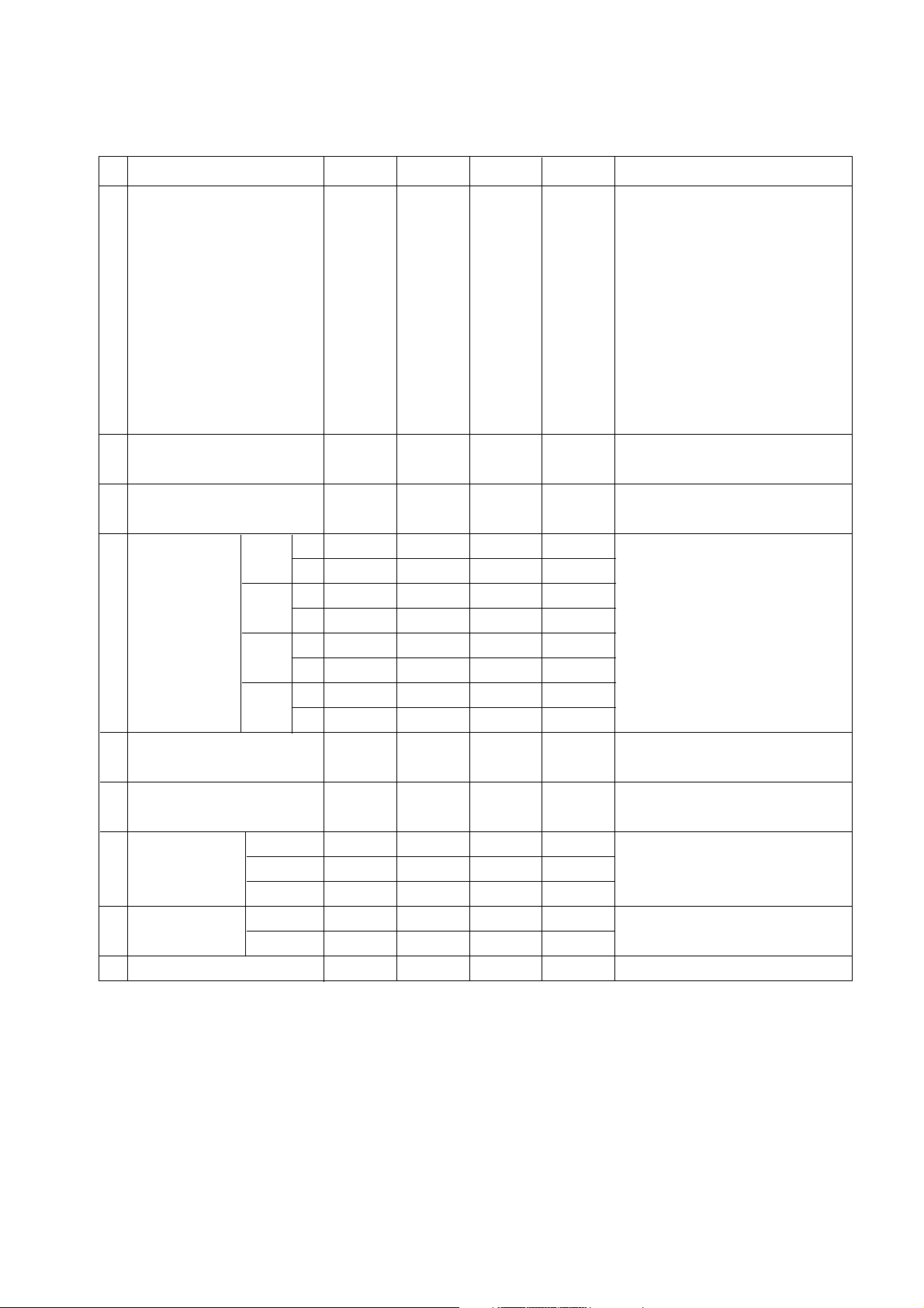
SPECIFICATIONS
NOTE : Specifications and others are subject to change without notice for improvement
.
V Application Range
This spec is applied to the 50” PLASMA TV used PD61A Chassis.
V Specification
Each part is tested as below without special appointment.
1) Temperature : 25±5°C (77±9°F), CST : 40±5
2) Relative Humidity: 65±10%
3) Power Voltage: Standard Input voltage (100-240V~, 50/60Hz)
* Standard Voltage of each product is marked by models.
4) Specification and performance of each parts are followed each drawing and specification by part number in accordance with SBOM.
5) The receiver must be operated for about 20 minutes prior to the adjustment.
V Test Method
1) Performance : LGE TV test method followed.
2) Demanded other specification
Safety : CE, IEC specification
EMC : CE, IEC
V General Specification
1. Module Specification
1-1. 50” XGA MODULE
- 9 -
Chassis
PD61A 50PC1DV-EC The United Kingdom LG
Model Name Market Place Brand Remark
50PC1DV-EC
Safety : IEC/EN60065
EMI : EN55013
EMS : EN55020
The United Kingdom
TEST
Model ApplianceMarket Remark
Display Screen Device
Aspect Ratio
PDP Module
Operating Environment
Storage Environment
Input Voltage
1
2
3
4
5
6
No Item Specification Remark
50” Wide Color Display Module
16:9
PDP50X4,
RGB Closed Type
1)Temp. : 0~55deg
2)Humidity : 20~80%
3)Temp. : -20~60deg
4)Humidity : 10~90%
100-240V~, 50/60Hz
Plasma Display Panel
LGE SPEC.
Maker : LGIT
Page 10
- 10 -
2. Model Specification ( 50” X4 module, Set with 38% Filter)
White peak Brightness
White average brightness
Brightness uniformity
Color Coordinate White X
Y
Red X
Y
Green X
Y
Blue X
Y
Color coordinate uniformity
Contrast ratio at dark room
Color Temperature Normal
Warm
Cool
Color pull in Range PAL
NTSC
Color killer Sensitivity
300
60
-10
0.275
0.280
0.650
0.305
0.230
0.655
0.130
0.035
-0.01
3000:1
8300
5500
9500
-500
-500
320
75
0
0.285
0.290
0.665
0.320
0.245
0.670
0.145
0.050
Average
3500:1
9300
6500
10500
+10
0.295
0.300
0.680
0.335
0.260
0.685
0.160
0.065
+0.01
10300
7500
11500
+500
+500
-80
1
2
3
4
5
6
7
8
9
No Item Remark
(*) Peak Brightness Mode
- 1/100 ~ 3/100 white window pattern
(Typically 1% window size)
- APC : User (Decrease brightness
from dynamic mode until entering
the peak brightness mode,
brightness : below 7 on OSD Menu)
- HDMI PC(1366*768 / 60Hz ) input
- Peak Brightness Condition may
slightly different between Sets.
- Full White Pattern
- APC : Clear (Dynamic)
- 85IRE Full White Pattern
- APC : Clear (Dynamic)
- 85IRE Full White Pattern
- APC : Clear (Dynamic)
- 85IRE Full White Pattern
- APC : Clear (Dynamic)
(*) Same as
Peak Brightness Mode Condition
- 85IRE Full White Pattern
- APC : Clear (Dynamic)
cd/m
2
cd/m
2
%
Hz
Hz
dBm
Min Typ Max Unit
Page 11

- 11 -
4. Model General Specification
3. General Specifications(PDP 50X4)
Market
Broadcasting system
Receiving system
Scart Jack (3EA)
Video Input (2EA)
S-Video Input (1EA)
Component Input (1EA)
RGB Input
HDMI Input(2EA)
Audio Input (4EA)
Wired Control(2EA)
1
2
3
4
5
6
7
8
9
10
11
No Item Specification Remark
The United Kingdom
1) PAL-BG
2) PAL-DK
3) PAL-I, I’
4) DVB-T(ID TV)
Analog : Upper Heterodyne
Digital : COFDM
PAL, SECAM
PAL, SECAM, NTSC
PAL, SECAM, NTSC
Y/Cb/Cr, Y/Pb/Pr
RGB-PC,
RGB-DTV
HDMI-PC
HDMI-DTV & SOUND
PC Audio, Component, AV(2EA)
Discrete IR(Input, Output)
UK
Scart 3 Jack is only DTV output
4 System : PAL, SECAM, NTSC, PAL60
4 System : PAL, SECAM, NTSC, PAL60
VGA model has only 1 HDMI input
L/R Input
Display area
Outline dimension
Number of Pixels
Cell pitch
Pixel type
Weight(net)
Weight(gross)
Operation Environment Temperature
Humidity
Pressure
Storage Environment Temperature
Humidity
Pressure
I mage stick minimization Start time
mode Low Brightness
Arrival Time
1106.5(H) * 622.1(V) °
± 0.5
1190(H) * 700(V)*52(D) °
±1
1366(H) * 768(V)
270(H) *810(V)
RGB Closed type
19.7 20.2 20.7
278.7 279.2 284.2
0 ~ 55
20 ~ 80
800 ~ 1100
-20 ~ 60
10 ~ 90
700 ~ 1100
4.5 5 5.5
14 15 16
1
2
3
4
5
6
7
8
9
10
No Item Remark
1Pixel=3RGB Cells
1Pixel=3RGB Cells
5EA 1Box
Altitude : 0 to 2000M
mm
mm
um
Kg
Kg
deg
%
hPa
deg
%
hPa
min
min
Min Typ Max Unit
Page 12
- 12 -
ADJUSTMENT INSTRUCTIONS
1. Application Object
These instructions are applied to all of the 50” PLASMA TV,
PD61A Chassis.
2. Notes
(1) Because this is not a hot chassis, it is not necessary to use
an isolation transformer. However, the use of isolation
transformer will help protect test instrument.
(2) Adjustment must be done in the correct order.
(3) The adjustment must be performed in the circumstance of
25±5°C of temperature and 65±10% of relative humidity if
there is no specific designation.
(4) The input voltage of the receiver must keep 100-240V~,
50/60Hz.
(5) The receiver must be operated for about 15 minutes prior
to the adjustment.
O After RGB Full white HEAT-RUN Mode, the receiver must
be operated prior to adjustment.
O Enter into HEAT-RUN MODE
1) Press the POWER ON KEY on R/C for adjustment.
2) OSD display and screen display PATTERN MODE.
[ Set is activated HEAT-RUN without signal generator in
this mode.
[ Single color pattern(RED/BLUE/GREEN) of HEAT-RUN
mode uses to check PANEL.
Caution) If you turn on a still screen more than 20 minutes,
(Especially digital pattern, cross hatch pattern) after
image may be occur in the black level part of the screen.
3. Channel memory
3-1. Setting up the LGIDS
1) Install the LGIDS. (idsinst.exe)
2) After installation, restart your PC.
3) Extract [files.zip] to folder [c:\LGIDS\files].
4) Start LGIDS.
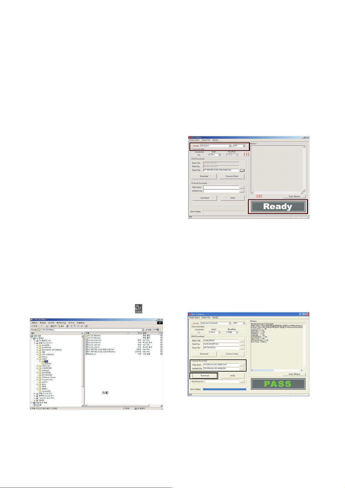
3-2. Channel memory Method
1) Select “PDP” and “Hurricane” on Model dialog. And check
your connection in Communication dialog. (If your
connection is ‘NG’, then set your PORT(COM1,2,3,...)
correctly.)
2) Connect RS-232C cable and turn on the power.
(If your connection has completed, you can see “Ready”.)
[ If your set is not an end products but only a board, you
have to make your board to Stand-by state (LED_R). And
you have to Download in Stand_by power state.
3) Select proper CH_memory file(*.nvm) for each model at
[NVRAM Download] $ [Write Batch]
Next, select proper binary file(*.bin) including the CH
information for each model at [NVRAM File].
File name : H2_CH_Memory_RZ.nvm
4) Click the [Download] button.
It means the completion of the CH memory download if all
items show ‘OK’ and Status is changed by ‘PASS’ at the
lower right corner of the window.
5) If you want to check whether the CH information is
memorized correctly or not, click the [Verify] button.
And then compare NVRAM File(*.bin) with the CH
information downloaded.
(Fig. 1)
(Fig. 2)
(1)
(2)(2)
(4)
(3)
(Fig. 3)
Page 13
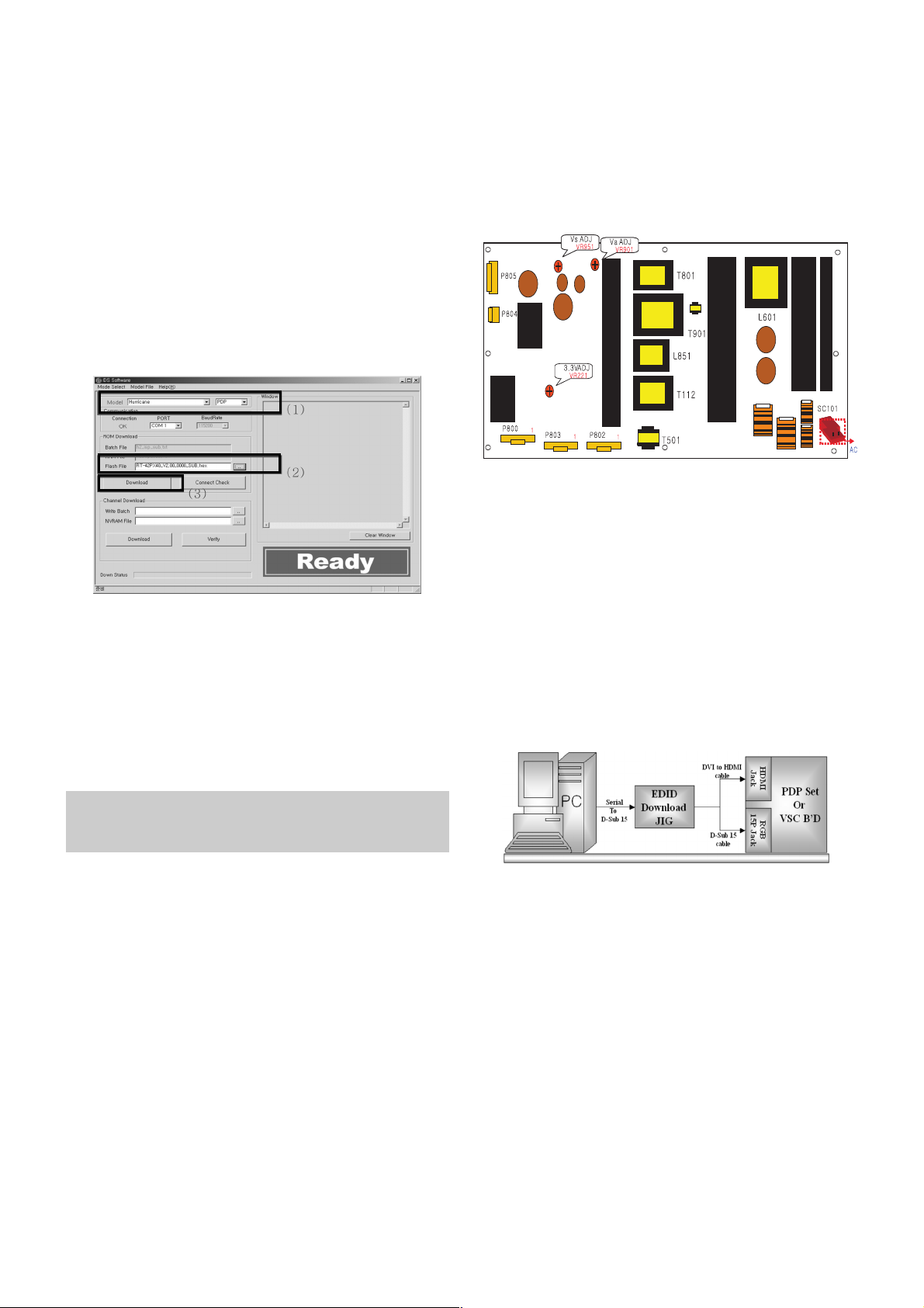
4. Sub Program Down Load
1) Select “ PDP” and “Hurricane” on Model dialog. and check
your connection in Communication dialog. (If your
connection is ‘NG’, then set your PORT(COM1,2,3,...)
correctly.
2) Connect RS232 cable and turn on the power. (Use the
special Cable for Sub-program)
(If your connection has completed, you can see ‘Ready’)
3) Select proper ‘Model’ for each model.
4) Select ‘flash file’ for each model.
5) Click the [Download] button.
It means the completion of the ROM download if all items
show ‘OK’ and Status is changed by ‘PASS’ at the lower
right corner of the window.
5. PCMCIA CARD Checking Method
1) You must adjust DTV 29 Channel and insert PCMCIA
CARD to socket.
2) If PCMCIA CARD works normally, normal signal display on
screen. But it works abnormally, “No CA module” words
display on screen.
6. POWER PCB Assy Voltage
Adjustments
(Va, Vs Voltage adjustments)
6-1. Test Equipment : D.M.M. 1EA
6-2.Connection Diagram for Measuring
: refer to Fig.5
6-3. Adjustment Method
(1) Va Adjustment
1) After receiving 100% Full White Pattern, HEAT RUN.
2) Connect + terminal of D.M.M to Va pin of P805, connect
- terminal to GND pin of P805.
3) After turning VR0901, voltage of D.M.M adjustment as
same as Va voltage which on label of panel right/top.
(Deviation; ±0.5V)
(2) Vs Adjustment
1) Connect + terminal of D.M.M to Vs pin of P805, connect
– terminal to GND pin of P805.
2) After turning VR951, voltage of D.M.M adjustment as
same as Va voltage which on label of panel right/top.
(Deviation; ±0.5V)
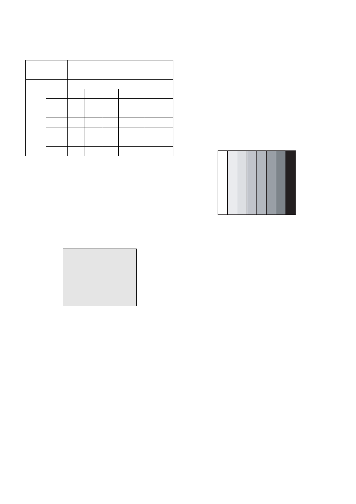
7. EDID (The Extended Display
Identification Data)/ DDC (Display
Data Channel) download
7-1. Required Test Equipment
1) Adjusting PC with S/W for writing EDID Data.(S/W : EDID
TESTER Ver.2.5)
2) A Jig for EDID Download.
3) Cable : Serial(9Pin or USB) to D-sub 15Pin cable, D-sub
15Pin cable, DVI to HDMI cable.
7-2. Setting of device
7-3. Preparation for Adjustment
1) As above Fig. 6, Connect the Set, EDID Download Jig, PC
& Cable.
2) Turn on the PC & EDID Download Jig. And Execute the
S/W : EDID TESTER Ver,2.5.
3) Set up S/W option.
Repeat Number : 5
Device Address : A0
PageByte : 8
4) Power on the Set.
- 13 -
Each PCB assembly must be checked by check JIG set.
(Because power PCB Assembly damages to PDP Module,
especially be careful)
(Fig. 5) Connection diagram of power adjustment for measuring
(Fig. 6) Connection Diagram of DDC download
(1)
(2)
(3)(3)
(Fig. 4)
Page 14

- 14 -
7-4. Sequence of Adjustment
- DDC data of Analog-RGB
1) Init the data.
2) Load the EDID data.(Open File).
[ Analog file ] (for RGB)
[ Digital file ] (for GDMI)
3) Set the S/W as below.
4) Push the “Write Data & Verify”button. And confirm “Yes”.
5) If the writing is finished, you will see the “OK” message.
8. Auto AV(CVBS) Color Balance
8-1. Requirement
V This AV color balance adjustment should be performed
before white Balance Adjustment.
V It is very import to use adjustment pattern like Fig.7.
1) Within the pattern, color sequence should be aligned.
: W-Y-C-G-M-R-BLUE-BLACK.
(If color sequence is reversed (Black -> ... -> White),
reverse the pattern with REV key, when using Master
pattern generator like MSPG-925)
2) If minimum Black level and/or maximum White level is
not correct, select 100% color bar pattern.
8-2. Required Equipment
1) Remote controller for adjustment.
2) AV Pattern Generator.
: 802F Pattern Generator, Master(MSPG-925FA), etc.
(Which has PAL Composite Video format output with
standard(1.0 Vpp) Vertical 100% Color Bar Pattern as Fig.7)
8-3. Method of Auto AV(CVBS) Color Balance
1) Input the PAL Composite Video into video input.
(Input 50Hz : AV3/AV4 Input)
2) Set the PSM to Standard mode in Picture menu.
3) Press IN-STAR key on R/C for adjustment.
4) Press the
G(Vol. +) key operate to set, then it becomes
automatically.
5) Auto-RGB OK means completed adjustment.
9. Adjustment of White Balance
9-1. Required Equipment
1) Remote controller for adjustment.
2) Color Analyzer. (CA-100 or same product)
3) Auto W/B adjustment instrument(only for Auto adjustment)
4) AV Pattern Generator.
9-2. Connecting diagram of equipment for
measuring (For Auto Adjustment)
(Fig. 7) Auto AV(CVBS) Color Balance Test Pattern
(Fig. 8) Connection Diagram of Auto W/B Adjustment
Page 15
- 15 -
W Auto adjustment Map(RS-232C)
9-3. Adjustment of White Balance
(For Manual adjustment)
O Operate the zero-calibration of the CA-100, then stick
sensor to PDP module surface when you adjust.
O For manual adjustment, it is also possible by the following
sequence.
1) Select white pattern of heat-run mode by pressing power on
key on remote control for adjustment then operate heat run
more than 15 minutes.
2) As below Fig.9, Supply 216Level (85 IRE) full screen
pattern to Video input.
(Input 50Hz, PD61A/C all model : AV4 Input)
3) Press the TV/AV KEY on R/C for converting input mode.
4) Set the PSM to Standard mode in Picture menu.
5) Enter the White Balance adjustment mode by pressing the
IN-START key twice(White Balance) on R/C.
6) Stick sensor to center of the screen and select each items
(Red/Green/Blue Gain and Offset) using
D / E(CH +/-) key
on R/C.
7) Adjust Only High Light with R Gain/ B Gain using
F / G
(VOL+/-) key on R/C.
8) Adjust it until color coordination becomes as below.
(Initially, R/G/B gain and R/G/B offset values are fixed as
below.
Red Gain : 82, Green Gain : 80, Blue Gain : 86
Red Offset : 7F, Green Offset : 7E, Blue Offset : 82)
[PD61A]-VGA 42”, XGA 42”,50” Module.
Brightness : High Light : 60 ± 20cd/m2
Color-Coordinate : High Light : X : 0.285 ± 0.003
Y : 0.290 ± 0.003
Color Temperature : 9,300°K ± 500°K.
9) When adjustment is completed, Exit adjustment mode using
EXIT key on R/C.
10. Auto Component Color Balance
10-1. Requirement
- It is very import to use correct adjustment pattern like fig.10.
V Within the pattern, color sequence should be aligned.
: W-Y-C-G-M-R-BLUE-BLACK.
(If color sequence is reversed(Black -> ... > White), reverse
the pattern with REV key, when using Master pattern.
generator like MSPG-925)
V If Minimum Black Level and/or Maximum White Level is not
correct, select 100% Color Bar Pattern.
10-2. Required Test Equipment
1) Remote controller for adjustment
2) 802F Pattern Generator
(Which has 720p Ypbpr output with Standard(0.7Vpp)
Vertical 100% Color Bar Pattern as Fig.10)
10-3. Method of auto component color balance
1) Input the Component 720p 100% Color Bar signal into
Component1 or Component2.
2) Set the PSM to Standard mode in Picture menu.
3) Press IN-START key on R/C for adjustment.
4) Press the
G(Vol. +) key operate to set, then it becomes
automatically.
5) Auto-RGB OK means complete adjustment
11. Auto RGB Color Balance
11-1. Requirement
- It is very import to use correct adjustment pattern like fig.11
V Within the pattern, color sequence should be aligned.
: W-Y-C-G-M-R-BLUE-BLACK.
(If color sequence is reversed(Black -> ... > White), reverse
the pattern with REV key, when using Master pattern
generator like MSPG-925)
V If Minimum Black Level and/or Maximum White Level is not
correct, Do select 100% Color Bar Pattern.
11-2. Required Test Equipment
1) Remote controller for adjustment.
2) 802F Pattern Generator, Master(MSPG-925FA), etc.
(Which has XGA 60Hz PC Format output with standard
(0.7Vpp) 100% Color Bar Pattern as Fig.11)
(Fig. 10) Auto Component Color Balance Test Pattern
(Fig. 9) Pattern for Adjustment of White Balance
216 Level (85 IRE)216 Level (85 IRE)
Type
Baud Rate
115200
Index
R Gain
G Gain
B Gain
R Offset
G Offset
B Offset
Data bit
8
Cmd1 Cmd2
ja
jb
jc
jd
je
jf
Stop bit
1
Parity
NONE
PD61A/C
Protocol
Setting
Data Min Value
00(00)
00(00)
00(00)
00(00)
00(00)
00(00)
Max Value
255(FF)
255(FF)
255(FF)
255(FF)
255(FF)
255(FF)
Page 16

- 16 -
11-3. Method of Auto RGB Color Balance
1) Input the PC 1024x768 60Hz 100%Color bar into RGB.
2) Set the PSM to Standard mode in Picture menu.
3) Press ADJ key on R/C for adjustment.
4) Press the
G(Vol. +) key operate To set, then it becomes
automatically.
5) Auto-RGB OK means completed adjustment.
12. Default value in adjustment mode
( Default valued maybe modified during E/S & L/P Event for
adjustment time reduction, but will be fixed beforeMass Production.)
12-1. Auto Color Balance (Component/RGB)
12-2. White Balance
13. EEPROM Data Write
13-1. Signal TABLE
CMD : A0h
LENGTH : 85~94h (1~16 bytes)
ADH : E2PROM Sub Address high (00~1F)
ADL : E2PROM Sub Address low (00~FF)
Data : Write data
CS :
CMD + LENGTH + ADH + ADL + Data_1 + ... + Data_n
Delay : 20ms
13-2. Command Set
* Description
FOS Default write : <7mode data> write
Vtotal, V_Frequency, Sync_Polarity, Htotal, Hstart, Vstart, 0, Phase
Data write : Model Name and Serial Number write in EEPROM,.
13-3. Method & notice
1) Serial number D/L is using of scan equipment.
2) Setting of scan equipment operated by Manufacturing
Technology Group.
3) Press FRONT-AV on control R/C before Serial number D/L.
4) Serial number D/L must be conformed when it is produced
in production line, because serial number D/L is mandatory
by D-book 4.0.
(Fig. 13) Default Value on OSD
(Fig. 12) Default Value on OSD
(Fig. 11) Auto RGB Color Balance Test Pattern
CMD
LENGTH
ADH ADL
DATA_1 DATA_N
... CS DELAY
No
1
EEPROM WRITE
A0h 84h+n n-byted Write
(n=1~16)
Adjust mode CMD(hex) LENGTH(hex) Description
Page 17

- 17 -
TROUBLE SHOOTING GUIDE
1. Power Board
1-1. The full flowchart for the voltage output
Start check
Manufacture’s model
passage
1. Check the Power Off
status.
Does the whole
screen appear?
Is it
identical to when the
power is off?
No
Yes
No
Yes
Yes
Yes
Yes
2. Check the Interface
signal status.
Is the Interface
signal operating?
Yes
3. Check the St-by 5V
signal circuit.
Does the
low pressure output
appear?
Does the
St-by 5V signal
appear?
No
No
Yes
4. Check the 5V Monitor
signal circuit.
Does the
5V Monitor signal
appear?
No
7. Check the VSC Vs-ON
signal
Does the
high tension output
appear?
Does the
VSC signal Vs-ON
appear?
No
No
Does the
high tension
output voltage
occur?
When
removing the Y B/D
Module input connector,
does output voltage
drop?
When the
Y, Z B/D Module
input connector, does Power
Board high tension
output voltage drop?
No No No
9. Check the Power
Board Output high
tension circuit
Yes
10. Check the Z B/D
Module output circuit
Yes
When
removing the Z B/D
Module input connector,
does output voltage
drop?
11. Check the Y B/D
Module output circuit
Yes
Yes
8. Check the Vs, Va
voltage output circuit.
Does the
Vs, Va voltage output
appear?
No
Yes
Yes
5. Check the VSC RL-ON
signal.
Does the
VSC signal RL-ON
appear?
No
6. Check the VSC low
pressure output
Does the
VSC low pressure
output appear?
No
Page 18

- 18 -
1-2.Power Board Structure
T801: Vs Trans
T901: Va Trans
T902: Vs aux. Trans
L851: Vs Inductor
T112: Low Voltage Trans
T501: ST-BY Trans
T601: PFC Inductor
Page 19

- 19 -
2. In case of strange screen display in specific modes
2-1. In case of no OSD display
(1) Symptom
1) LED is white.
2) The minute discharge is continuously accomplished from the module.
(2) Follow check
Is the LVDS cable
normal ?
Is the VSC Board
normal?
Is the LVDS cable
connected?
Re-insert the Cable.
Yes
No
No
Yes
Does the FIL8532 IC
(IC800) Operate?
Replace the FIL8532 IC
(IC800).
No
Is the Ctrl Board of
Module normal?
Replace the Ctrl B/D.
No
No
Yes
Replace the VSC B/D
Replace the cable.
Yes
Page 20

- 20 -
2-2. In case of there is no display on the screen in specific modes
(1) Symptom
1) There is no screen display from a specific input mode
(RF, AV, Component, RGB, DVI).
(2) Check following
1) Check the all input mode should become normality display
.
2) Check the Video(Main)/Data(Sub), Video(Main)/Video(Sub) should become
normality display from the PIP mode or DW mode. (Re-Check it Swap)
(3) In case of an unusual display in TV mode RF mode
(4) In case of an unusual display in TV mode AV mode
(5) In case of an unusual display in TV mode Component, RGB-DTV/ PC mode
(6) In case of an unusual display in TV mode HDMI mode
Is the Tuner normal?
Is the CXA2069Q
normal?(IC300)
Is the Tuner Cable
connected?
Re-insert the cable
Yes
No
No
Yes
Is the FIL8532(IC800)
normal?
Replace the Tuner.
No
Are the Input voltage, IIC Communication
and CVBS output normal?
Yes
Are the Input voltage, IIC
Communication and HV sync
normal?
No
Replace the IC.
No
Are the Input voltage, IIC
Communication and HV sync
normal?
No
Replace the IC.
No
Is the CXA2069Q
normal?
Yes
Is the FIL8532
normal?
Are the Input voltage, IIC
Communication and HV sync
normal?
No
Replace the IC.
No
Are the Input voltage, IIC
Communication and HV sync
normal?
No
Replace the IC.
No
Is the FIL8532
normal?
Are the Input voltage, IIC
Communication and HV sync
normal?
No
Replace the IC.
No
Is the Sil9011
normal?
Yes
Is the FIL8532
normal?
Are the Input voltage, IIC
Communication and HV sync
normal?
No
Replace the IC.
No
Are the Input voltage, IIC
Communication and HV sync
normal?
No
Replace the IC.
No
Page 21

- 21 -
3. In case of no sound
(1) Symptom
1) LED is white.
2) Screen display appears but there is no sound.
(2) Follow Check
Replace the IC404.
Is the RF/ AV/
Component/ RGB/
HDMI sound normal?
No
Is the MSP4410K
(IC404) normal?
Replace the IC403.
Yes
Is the NSP2100
(IC403) normal?
Replace the IC405.
Yes
Is the TAS5122
(IC405) normal?
Replace the IC800.
Yes
Yes
No No No
No
Is the FLI8532
(IC404) normal?
Replace the
VSC B/D.
Is the SPK cable
normal?
Is the SPK cable
connected?
Re-insert the cable
No
No
Is the Flat cable
connected?
Re-insert the cable
No
Replace the SPK cable.
Yes
Yes
Yes
Page 22

- 22 -
BLOCK DIAGRAM
Comp
(DVD/DTV)
Rx0/1,Tx0/1
IR/TX
SCL/SDA
H/V(RGB)
SCL/SDA
Rx0/1/2/C•
ICL3232C
24LC02BT
74HC14D
24LC02BT
Hudson
( Sub CH.
Decoding /
2D Comb /
2D De-int. /
Scaling )
CXA2069Q
A/V Switch
Tuner
TU_Main
Sil9012
TMDS Rx
(HDCP)
RGB_PC /DTV
RGB H/V
RGB H/V
Cortez
( Main CH.
Decoding /
3D Comb /
3D De-int. /
Scaling & FRC /
PIP Mux. /
GUI /
VSB Decoding /
Audio Delay /
CPU )
I
2
C
RS232_Rx/Tx_Cortez
Side-AV B D
AV
S-AV
YCin5
HY5DU281622E
DDRRAM (128MB X2)
AM29LV
F-ROM (2MB)
PC_Audio LR
SIF
AM_Audio
AVin5
MSP4410K
Audio SW &
Tone Control
NSP2100A
PWM Mod .
TAS5112
Digital Amp
LRCK/LRCH
SCK
R_SPK_out
AV_LR
PC_Audio LR
AM_Audio, SIF
I
2
S
Comp
Scart_RGB / FB
Comp_L/R
AVin2 (YC/CVBS/L/R/Scart_ID)
AVin4(CVBS/L/R)
YCin4
V or Y / C (Main)
L_CH
R_CH
DTV_LRout
LVDS_31P
/
Tx0/1/2/3/C•
Disp_En
SCL /SDA
V_out1
Y_in1
V or Y / C (Sub)
/
L_SPK_out
I
2
S
I
2
S
I
2
C
For DDC_RGB
For DDC_HDMI
I
2
C
RGB
(PC/DTV)
HDMI
(PC/DTV)
RS232
R/C OUT
Scart1
Scart2
DTV OUT
AV
S-AV
PC_Audio
TV_out (CVBS/L/R)
AVin1 (CVBS/L/R/Scart_ID)
DTV_out (CVBS/L/R)
CI SLOT
STi5100
Tuner
4M BYTE
FRESH
MEMORY
HY5DU561622D
DDRRAM (256MB)
T.S 7 , SYNC,CK,VALID
74LVC541
74LVC
541
74LVC
245
CVBS
27MHZ
CRYSTAL
YCbCr 656 Format _8bit
DIGITAL
ANALOG
/
Spliter
SN74
LVTH541
I
2
C
URAT_DATA_IN/OUT
IN
OUT
Wired-or 8bit
I
2
C
I
2
C
MNT_out (CVBS/L/R) ,SOUND MUTE
I
2
S (HDM I Sound) 3bit
TV_LRout
CVBS
SN74
LVTH541
/
I
2
S , 27M CLK _4bit
SPDIF OUT
SPDIF_out
SPDIF_out_A
/
/
HDMI_Data
24bit_A
H/V SYNC,CLK,DE 4bit
HDMI_Data
24bit_B
H/V SYNC,CLK,DE
4bit
EPF_R/L
RS232_Rx/Tx_Hud
74LCX157
RS232_Rx/Tx_STi
RS232_Rx/Tx_STi
Comp
24bit_A
24bit_B
I
2
S (DTV Sound) 3bit
27M CLK
DTV_LRout
TV_LRout
Comp (Y/Pb/Pr)
Comp_L/R
L_CH
R_CH
Variable_L/R
Variable_L/R
74LCX157
SPDIF_out_B
SPDIF_out_B
SPDIF_out_A
R/C IN
74LVC541
Page 23

MEMO
- 23 -
Page 24

- 24 -
EXPLODED VIEW
305
303
302
301
304
200
201
202
203
204
240
400
250
205
206
208
101
207
501
502
520
530
580
300
121
560
120
570
600
602
601
431
430
Page 25

- 25 -
EXPLODED VIEW PARTS LIST
101 5900904001A Fan Module, 1.7KRPM DC 12V 250UA 3W 50HZ 1.5M3 per MIN 396X60.2X108.3MM DONGYANG CHEMICAL
120 EAB30829601 Speaker, Woofer g2060102 ND 15W 8OHM 82DB 100HZ 240 X 57 X 49 LUG MACOM
121 EAB30824301 Speaker, Tweeter D013d03k1401 ND 15W 8OHM 86DB 0HZ 88 X 38.3 X 10 LUG
200 EAJ37049801 PDP, Module-XGA PDP50X40400.ASLGB XGA 50INCH 1365X768 16/9 PDP DIVISION
201 6871QCH083A Hand Insert PCB Assembly, CTRL Board CTRL ASS’Y HAND INSERT 50” CTRL PDP DIVISION
202 6871QDH115A Hand Insert PCB Assembly, Y DRIVE TOP YDRV ASS’Y HAND INSERT 50” X4 PDP DIVISION
203 6871QDH116A Hand Insert PCB Assembly, Y DRIVE BOTTOM YDRV ASS’Y HAND INSERT 50” X4 YDRV BTM PDP DIVISION
204 6871QLH063A Hand Insert PCB Assembly, X_LEFT BOARD XRLT ASS’Y HAND INSERT 50” X4 PDP DIVISION
205 6871QRH073A Hand Insert PCB Assembly, X_RIGHT BOARD XRRT ASS’Y HAND INSERT 50” X4 PDP DIVISION
206 6871QXH034A Hand Insert PCB Assembly, X_CENTER BOARD XRCT ASS’Y HAND INSERT 50” X4 PDP DIVISION
207 EBR36223601 Hand Insert PCB Assembly, EBR36223601 YSUS ASS’Y HAND INSERT 50” X4. Adapted OSP. PDP DIVISION
208 EBR36223801 Hand Insert PCB Assembly, EBR36223801 ZSUS ASS’Y HAND INSERT 50” X4. Adapted OSP. PDP DIVISION
240 4980900101C Supporter, ASSY AL VERTICAL Right SKD
250 4980900102C Supporter, ASSY AL VERTICAL Left SKD
300 30919E0004Y Cover Assembly, 50PC1DA-EC FOR SKD PD62A 50” FOR SKD
301 4980900103B Supporter, FILTER AL 50PC3D-UD.SUSULLJR
302 4980900104B Supporter, FILTER AL 50PC3D-UD.SUSULLJR BOTTOM
303 4980900105B Supporter, FILTER AL 50PC3D-UD.SUSULLJR RIGHT
304 4980900106B Supporter, FILTER AL 50PC3D-UD.SUSULLJR LEFT
305 5230V00017D Filter , CUTTING ACRYL TOP 50” PDP MITSUI 50” GLASS FILTER
400 3809900102G Cover Assembly , 50PC1DR-UA.SUSLLJR NON SKD
430 3501900004B Base Assembly, STAND 50PC1R-TA PA61A SKD
431 35509K0101A Cover, MOLD HIPS 50PC1R-TA CABLE NON
501 3301900089D Plate Assembly, AV VTCP-PRESS
502 3301900092M Plate Assembly, ASSY DIGITAL COVER ASSY 2HDMI
520 68719MMX24A Hand Insert PCB Assembly, Main MAIN1 M.I PD61A 50PC1D-EC AEKLLHX -
530 68719SMM59A Hand Insert PCB Assembly, Sub M.I PD61A 50PC1D-EC AEKLLHX -
560 68719SML96A Hand Insert PCB Assembly, Sub M.I PD61A 42PC1DV-EC SEKLLJP -
570 68719SMM33A Hand Insert PCB Assembly, Sub M.I PD61A 42PC1D-EC SEKLLJP -
580 6709900020B Power Supply Assembly, 50INCH UNIFAICATION PSU PDP LGIT PA61A 530W 50PB2DR
600 68719SMJ15A Hand Insert PCB Assembly, Sub M.I PD61A 42PC1DV-EC AEKLLAX -
601 4811900021C Bracket Assembly, SIDE AV 42PC1R-ZH PP62A CORTEZ-A, EU
602 48149V0003B Plate, PRESS SPTE T0.3 SIDE AV 50PC1R
No. Part No. Descriptions
The components identified by mark is
critical for safety.
Replace only with part number specified.
Page 26

- 26 -
C1 0CH3104K566 0805B104K500CT 100nF 10% 50V X7R -5
C100 0CE106WFKDC MVK4.0TP16VC10M 10uF 20% 16V 16MA -
C100 0CC050CK11A C1608C0G1H050DT 5pF 0.5PF 50V C0G -
C1000 0CE477WF6DC MVK10TP16VC470M 470uF 20% 16V 80MA
C1001 0CK104CK56A 0603B104K500CT 100nF 10% 50V X7R -5
C1002 0CK474CH94A 0603F474Z250CT 470nF -20TO+80% 25V
C1003 0CK474CH94A 0603F474Z250CT 470nF -20TO+80% 25V
C1004 0CK103CK56A 0603B103K500CT 10nF 10% 50V X7R -55
C1005 0CE477WF6DC MVK10TP16VC470M 470uF 20% 16V 80MA
C1006 0CK104CK56A 0603B104K500CT 100nF 10% 50V X7R -5
C1007 0CE107WF6DC MVK6.3TP16VC100M 100uF 20% 16V 80MA
C1008 0CK104CK56A 0603B104K500CT 100nF 10% 50V X7R -5
C1009 0CE107WF6DC MVK6.3TP16VC100M 100uF 20% 16V 80MA
C101 0CC050CK11A C1608C0G1H050DT 5pF 0.5PF 50V C0G -
C101 0CK104CF56A 0603B104K160CT 100nF 10% 16V X7R -5
C101 0CH5101K416 C2012C0G1H101JT 100pF 5% 50V C0G -5
C101 0CH5101K416 C2012C0G1H101JT 100pF 5% 50V C0G -5
C1011 0CK103CK56A 0603B103K500CT 10nF 10% 50V X7R -55
C1013 0CK104CK56A 0603B104K500CT 100nF 10% 50V X7R -5
C1014 0CK103CK56A 0603B103K500CT 10nF 10% 50V X7R -55
C1015 0CE107WF6DC MVK6.3TP16VC100M 100uF 20% 16V 80MA
C1017 0CK103CK56A 0603B103K500CT 10nF 10% 50V X7R -55
C1018 0CK104CK56A 0603B104K500CT 100nF 10% 50V X7R -5
C1019 0CE476WF6DC MVK6.3TP16VC47M 47uF 20% 16V 80MA -
C102 0CK105CD56A C1608X7R1A105KT 1uF 10% 10V X7R -55
C102 0CC050CK11A C1608C0G1H050DT 5pF 0.5PF 50V C0G -
C102 0CH5101K416 C2012C0G1H101JT 100pF 5% 50V C0G -5
C102 0CH5330K416 C2012C0G1H330JT 33pF 5% 50V C0G -55
C1029 0CK104CK56A 0603B104K500CT 100nF 10% 50V X7R -5
C103 0CE4763F618 ESF476M016T1A5E05G 47uF 20% 16V 60M
C103 0CC050CK11A C1608C0G1H050DT 5pF 0.5PF 50V C0G -
C103 0CK104CF56A 0603B104K160CT 100nF 10% 16V X7R -5
C1030 0CE476WF6DC MVK6.3TP16VC47M 47uF 20% 16V 80MA -
C1035 0CK104CK56A 0603B104K500CT 100nF 10% 50V X7R -5
C104 0CE4763F618 ESF476M016T1A5E05G 47uF 20% 16V 60M
C104 0CC050CK11A C1608C0G1H050DT 5pF 0.5PF 50V C0G -
C104 0CK104CF56A 0603B104K160CT 100nF 10% 16V X7R -5
C1040 0CK103CK56A 0603B103K500CT 10nF 10% 50V X7R -55
C1043 0CE476WF6DC MVK6.3TP16VC47M 47uF 20% 16V 80MA -
C1044 0CK104CK56A 0603B104K500CT 100nF 10% 50V X7R -5
C1045 0CK104CK56A 0603B104K500CT 100nF 10% 50V X7R -5
C1046 0CE477WF6DC MVK10TP16VC470M 470uF 20% 16V 80MA
C1047 0CE476WF6DC MVK6.3TP16VC47M 47uF 20% 16V 80MA -
C1048 0CK104CK56A 0603B104K500CT 100nF 10% 50V X7R -5
C1049 0CK104CK56A 0603B104K500CT 100nF 10% 50V X7R -5
C105 0CE4763F618 ESF476M016T1A5E05G 47uF 20% 16V 60M
C105 0CC050CK11A C1608C0G1H050DT 5pF 0.5PF 50V C0G -
C105 0CK104CF56A 0603B104K160CT 100nF 10% 16V X7R -5
C1050 0CE477WF6DC MVK10TP16VC470M 470uF 20% 16V 80MA
C1051 0CE477WF6DC MVK10TP16VC470M 470uF 20% 16V 80MA
C1052 0CK104CK56A 0603B104K500CT 100nF 10% 50V X7R -5
C1053 0CK103CK56A 0603B103K500CT 10nF 10% 50V X7R -55
C1054 0CK104CK56A 0603B104K500CT 100nF 10% 50V X7R -5
C1055 0CK104CK56A 0603B104K500CT 100nF 10% 50V X7R -5
C1056 0CK104CK56A 0603B104K500CT 100nF 10% 50V X7R -5
C1057 0CK104CK56A 0603B104K500CT 100nF 10% 50V X7R -5
C1058 0CK104CK56A 0603B104K500CT 100nF 10% 50V X7R -5
C1059 0CK103CK56A 0603B103K500CT 10nF 10% 50V X7R -55
C106 0CC050CK11A C1608C0G1H050DT 5pF 0.5PF 50V C0G -
C106 0CK104CF56A 0603B104K160CT 100nF 10% 16V X7R -5
C1060 0CK103CK56A 0603B103K500CT 10nF 10% 50V X7R -55
C1061 0CK103CK56A 0603B103K500CT 10nF 10% 50V X7R -55
C1062 0CK103CK56A 0603B103K500CT 10nF 10% 50V X7R -55
C1063 0CK103CK56A 0603B103K500CT 10nF 10% 50V X7R -55
C1064 0CE476WF6DC MVK6.3TP16VC47M 47uF 20% 16V 80MA -
C1065 0CE476WF6DC MVK6.3TP16VC47M 47uF 20% 16V 80MA -
C1066 0CE476WF6DC MVK6.3TP16VC47M 47uF 20% 16V 80MA -
C1067 0CE476WF6DC MVK6.3TP16VC47M 47uF 20% 16V 80MA -
C1068 0CE476WF6DC MVK6.3TP16VC47M 47uF 20% 16V 80MA -
C1069 0CE476WF6DC MVK6.3TP16VC47M 47uF 20% 16V 80MA -
C107 0CK105CD56A C1608X7R1A105KT 1uF 10% 10V X7R -55
C107 0CC050CK11A C1608C0G1H050DT 5pF 0.5PF 50V C0G -
C1070 0CK104CK56A 0603B104K500CT 100nF 10% 50V X7R -5
C1071 0CE477WF6DC MVK10TP16VC470M 470uF 20% 16V 80MA
C1072 0CK104CK56A 0603B104K500CT 100nF 10% 50V X7R -5
C1073 0CE477WF6DC MVK10TP16VC470M 470uF 20% 16V 80MA
C1074 0CK104CK56A 0603B104K500CT 100nF 10% 50V X7R -5
C1075 0CK104CK56A 0603B104K500CT 100nF 10% 50V X7R -5
C1076 0CK104CK56A 0603B104K500CT 100nF 10% 50V X7R -5
C1077 0CK104CK56A 0603B104K500CT 100nF 10% 50V X7R -5
C1078 0CK103CK56A 0603B103K500CT 10nF 10% 50V X7R -55
C1079 0CK103CK56A 0603B103K500CT 10nF 10% 50V X7R -55
C108 0CE106WFKDC MVK4.0TP16VC10M 10uF 20% 16V 16MA -
C1080 0CK103CK56A 0603B103K500CT 10nF 10% 50V X7R -55
C1081 0CK103CK56A 0603B103K500CT 10nF 10% 50V X7R -55
C1082 0CE476WF6DC MVK6.3TP16VC47M 47uF 20% 16V 80MA -
C1083 0CE476WF6DC MVK6.3TP16VC47M 47uF 20% 16V 80MA -
C1084 0CE476WF6DC MVK6.3TP16VC47M 47uF 20% 16V 80MA -
C1085 0CE476WF6DC MVK6.3TP16VC47M 47uF 20% 16V 80MA -
C1086 0CK104CK56A 0603B104K500CT 100nF 10% 50V X7R -5
C1087 0CE477WF6DC MVK10TP16VC470M 470uF 20% 16V 80MA
C1088 0CK104CK56A 0603B104K500CT 100nF 10% 50V X7R -5
C1089 0CK104CK56A 0603B104K500CT 100nF 10% 50V X7R -5
C109 0CK103CK56A 0603B103K500CT 10nF 10% 50V X7R -55
C109 0CK104CF56A 0603B104K160CT 100nF 10% 16V X7R -5
C1090 0CK104CK56A 0603B104K500CT 100nF 10% 50V X7R -5
C1091 0CK104CK56A 0603B104K500CT 100nF 10% 50V X7R -5
C1092 0CK104CK56A 0603B104K500CT 100nF 10% 50V X7R -5
C1093 0CK103CK56A 0603B103K500CT 10nF 10% 50V X7R -55
LOC. NO. PART NO. DESCRIPTION / SPECIFICATION LOC. NO. PART NO. DESCRIPTION / SPECIFICATION
REPLACEMENT PARTS LIST
DATE: 2007. 04. 20.
CAPACITORs
Page 27

- 27 -
C1094 0CK103CK56A 0603B103K500CT 10nF 10% 50V X7R -55
C1095 0CK103CK56A 0603B103K500CT 10nF 10% 50V X7R -55
C1096 0CK103CK56A 0603B103K500CT 10nF 10% 50V X7R -55
C1097 0CK103CK56A 0603B103K500CT 10nF 10% 50V X7R -55
C1098 0CE476WF6DC MVK6.3TP16VC47M 47uF 20% 16V 80MA -
C1099 0CE476WF6DC MVK6.3TP16VC47M 47uF 20% 16V 80MA -
C110 0CK102CK56A 0603B102K500CT 1nF 10% 50V X7R -55T
C110 0CK104CF56A 0603B104K160CT 100nF 10% 16V X7R -5
C1100 0CK104CK56A 0603B104K500CT 100nF 10% 50V X7R -5
C1101 0CK103CK56A 0603B103K500CT 10nF 10% 50V X7R -55
C1102 0CE476WF6DC MVK6.3TP16VC47M 47uF 20% 16V 80MA -
C1103 0CK104CK56A 0603B104K500CT 100nF 10% 50V X7R -5
C1104 0CK103CK56A 0603B103K500CT 10nF 10% 50V X7R -55
C1105 0CE107WF6DC MVK6.3TP16VC100M 100uF 20% 16V 80MA
C1106 0CK104CK56A 0603B104K500CT 100nF 10% 50V X7R -5
C1107 0CE476WF6DC MVK6.3TP16VC47M 47uF 20% 16V 80MA -
C1108 0CK103CK56A 0603B103K500CT 10nF 10% 50V X7R -55
C1109 0CK104CK56A 0603B104K500CT 100nF 10% 50V X7R -5
C111 0CK103CK56A 0603B103K500CT 10nF 10% 50V X7R -55
C111 0CK104CF56A 0603B104K160CT 100nF 10% 16V X7R -5
C1110 0CE477WF6DC MVK10TP16VC470M 470uF 20% 16V 80MA
C1111 0CK104CK56A 0603B104K500CT 100nF 10% 50V X7R -5
C1112 0CK104CK56A 0603B104K500CT 100nF 10% 50V X7R -5
C1113 0CK103CK56A 0603B103K500CT 10nF 10% 50V X7R -55
C1114 0CE476WF6DC MVK6.3TP16VC47M 47uF 20% 16V 80MA -
C1115 0CK104CK56A 0603B104K500CT 100nF 10% 50V X7R -5
C1116 0CE476WF6DC MVK6.3TP16VC47M 47uF 20% 16V 80MA -
C112 0CK102CK56A 0603B102K500CT 1nF 10% 50V X7R -55T
C112 0CK104CF56A 0603B104K160CT 100nF 10% 16V X7R -5
C1125 0CK104CK56A 0603B104K500CT 100nF 10% 50V X7R -5
C1126 0CE477WF6DC MVK10TP16VC470M 470uF 20% 16V 80MA
C1129 0CK104CK56A 0603B104K500CT 100nF 10% 50V X7R -5
C113 0CK103CK56A 0603B103K500CT 10nF 10% 50V X7R -55
C113 0CK104CF56A 0603B104K160CT 100nF 10% 16V X7R -5
C1130 0CK104CK56A 0603B104K500CT 100nF 10% 50V X7R -5
C1133 0CK103CK56A 0603B103K500CT 10nF 10% 50V X7R -55
C1134 0CK103CK56A 0603B103K500CT 10nF 10% 50V X7R -55
C1137 0CE107WF6DC MVK6.3TP16VC100M 100uF 20% 16V 80MA
C1138 0CE107WF6DC MVK6.3TP16VC100M 100uF 20% 16V 80MA
C1139 0CK104CK56A 0603B104K500CT 100nF 10% 50V X7R -5
C114 0CK102CK56A 0603B102K500CT 1nF 10% 50V X7R -55T
C114 0CK104CF56A 0603B104K160CT 100nF 10% 16V X7R -5
C1140 0CK104CK56A 0603B104K500CT 100nF 10% 50V X7R -5
C1141 0CK104CK56A 0603B104K500CT 100nF 10% 50V X7R -5
C1142 0CK104CK56A 0603B104K500CT 100nF 10% 50V X7R -5
C1144 0CK103CK56A 0603B103K500CT 10nF 10% 50V X7R -55
C1145 0CK103CK56A 0603B103K500CT 10nF 10% 50V X7R -55
C1146 0CK103CK56A 0603B103K500CT 10nF 10% 50V X7R -55
C1147 0CK103CK56A 0603B103K500CT 10nF 10% 50V X7R -55
C1149 0CE107WF6DC MVK6.3TP16VC100M 100uF 20% 16V 80MA
C115 0CK104CF56A 0603B104K160CT 100nF 10% 16V X7R -5
C115 0CK103CK56A 0603B103K500CT 10nF 10% 50V X7R -55
C1150 0CE107WF6DC MVK6.3TP16VC100M 100uF 20% 16V 80MA
C1151 0CE107WF6DC MVK6.3TP16VC100M 100uF 20% 16V 80MA
C1152 0CE107WF6DC MVK6.3TP16VC100M 100uF 20% 16V 80MA
C1155 0CK104CK56A 0603B104K500CT 100nF 10% 50V X7R -5
C1157 0CK103CK56A 0603B103K500CT 10nF 10% 50V X7R -55
C1159 0CE476WF6DC MVK6.3TP16VC47M 47uF 20% 16V 80MA -
C116 0CE106WFKDC MVK4.0TP16VC10M 10uF 20% 16V 16MA -
C116 0CK102CK56A 0603B102K500CT 1nF 10% 50V X7R -55T
C1161 0CK104CK56A 0603B104K500CT 100nF 10% 50V X7R -5
C1162 0CE107WF6DC MVK6.3TP16VC100M 100uF 20% 16V 80MA
C1163 0CK104CK56A 0603B104K500CT 100nF 10% 50V X7R -5
C1164 0CK104CK56A 0603B104K500CT 100nF 10% 50V X7R -5
C1165 0CE107WF6DC MVK6.3TP16VC100M 100uF 20% 16V 80MA
C1166 0CE107WF6DC MVK6.3TP16VC100M 100uF 20% 16V 80MA
C1167 0CK104CK56A 0603B104K500CT 100nF 10% 50V X7R -5
C1168 0CK104CK56A 0603B104K500CT 100nF 10% 50V X7R -5
C1169 0CK104CK56A 0603B104K500CT 100nF 10% 50V X7R -5
C117 0CK104CK56A 0603B104K500CT 100nF 10% 50V X7R -5
C117 0CK104CF56A 0603B104K160CT 100nF 10% 16V X7R -5
C1170 0CK104CK56A 0603B104K500CT 100nF 10% 50V X7R -5
C1171 0CK104CK56A 0603B104K500CT 100nF 10% 50V X7R -5
C1172 0CK104CK56A 0603B104K500CT 100nF 10% 50V X7R -5
C1173 0CK104CK56A 0603B104K500CT 100nF 10% 50V X7R -5
C1174 0CK104CK56A 0603B104K500CT 100nF 10% 50V X7R -5
C1175 0CK104CK56A 0603B104K500CT 100nF 10% 50V X7R -5
C1176 0CK103CK56A 0603B103K500CT 10nF 10% 50V X7R -55
C1177 0CK103CK56A 0603B103K500CT 10nF 10% 50V X7R -55
C1178 0CK103CK56A 0603B103K500CT 10nF 10% 50V X7R -55
C1179 0CK103CK56A 0603B103K500CT 10nF 10% 50V X7R -55
C118 0CE106WH6DC MVK5.0TP25VC10M 10uF 20% 25V 25MA -
C118 0CK104CF56A 0603B104K160CT 100nF 10% 16V X7R -5
C1180 0CK103CK56A 0603B103K500CT 10nF 10% 50V X7R -55
C1181 0CK103CK56A 0603B103K500CT 10nF 10% 50V X7R -55
C1182 0CK103CK56A 0603B103K500CT 10nF 10% 50V X7R -55
C1183 0CK103CK56A 0603B103K500CT 10nF 10% 50V X7R -55
C1184 0CK103CK56A 0603B103K500CT 10nF 10% 50V X7R -55
C1185 0CE476WF6DC MVK6.3TP16VC47M 47uF 20% 16V 80MA -
C1186 0CE476WF6DC MVK6.3TP16VC47M 47uF 20% 16V 80MA -
C1187 0CE476WF6DC MVK6.3TP16VC47M 47uF 20% 16V 80MA -
C1188 0CE107WF6DC MVK6.3TP16VC100M 100uF 20% 16V 80MA
C1189 0CE107WF6DC MVK6.3TP16VC100M 100uF 20% 16V 80MA
C119 0CE106WH6DC MVK5.0TP25VC10M 10uF 20% 25V 25MA -
C119 0CK104CF56A 0603B104K160CT 100nF 10% 16V X7R -5
C1190 0CE107WF6DC MVK6.3TP16VC100M 100uF 20% 16V 80MA
C1191 0CE107WF6DC MVK6.3TP16VC100M 100uF 20% 16V 80MA
C1192 0CE107WF6DC MVK6.3TP16VC100M 100uF 20% 16V 80MA
C1193 0CE107WF6DC MVK6.3TP16VC100M 100uF 20% 16V 80MA
C1194 0CE477WF6DC MVK10TP16VC470M 470uF 20% 16V 80MA
C1197 0CK104CK56A 0603B104K500CT 100nF 10% 50V X7R -5
C1198 0CK103CK56A 0603B103K500CT 10nF 10% 50V X7R -55
C1199 0CE107WF6DC MVK6.3TP16VC100M 100uF 20% 16V 80MA
C120 0CE106WH6DC MVK5.0TP25VC10M 10uF 20% 25V 25MA -
C120 0CK104CF56A 0603B104K160CT 100nF 10% 16V X7R -5
C121 0CE106WH6DC MVK5.0TP25VC10M 10uF 20% 25V 25MA -
C121 0CK104CF56A 0603B104K160CT 100nF 10% 16V X7R -5
C122 0CK104CF56A 0603B104K160CT 100nF 10% 16V X7R -5
C123 0CK104CF56A 0603B104K160CT 100nF 10% 16V X7R -5
C124 0CK104CF56A 0603B104K160CT 100nF 10% 16V X7R -5
LOC. NO. PART NO. DESCRIPTION / SPECIFICATION LOC. NO. PART NO. DESCRIPTION / SPECIFICATION
Page 28

- 28 -
C1246 0CK104CK56A 0603B104K500CT 100nF 10% 50V X7R -5
C1247 0CE476WF6DC MVK6.3TP16VC47M 47uF 20% 16V 80MA -
C125 0CK104CF56A 0603B104K160CT 100nF 10% 16V X7R -5
C126 0CE227SF6DC MVG6.3TP16VC220M 220uF 20% 16V 130M
C126 0CK104CF56A 0603B104K160CT 100nF 10% 16V X7R -5
C127 0CK103CK56A 0603B103K500CT 10nF 10% 50V X7R -55
C127 0CK104CF56A 0603B104K160CT 100nF 10% 16V X7R -5
C128 0CK102CK56A 0603B102K500CT 1nF 10% 50V X7R -55T
C128 0CK104CF56A 0603B104K160CT 100nF 10% 16V X7R -5
C129 0CK103CK56A 0603B103K500CT 10nF 10% 50V X7R -55
C129 0CK104CF56A 0603B104K160CT 100nF 10% 16V X7R -5
C130 0CK102CK56A 0603B102K500CT 1nF 10% 50V X7R -55T
C130 0CK104CF56A 0603B104K160CT 100nF 10% 16V X7R -5
C131 0CE106WH6DC MVK5.0TP25VC10M 10uF 20% 25V 25MA -
C131 0CK104CF56A 0603B104K160CT 100nF 10% 16V X7R -5
C1310 0CE107WF6DC MVK6.3TP16VC100M 100uF 20% 16V 80MA
C1311 0CK103CK56A 0603B103K500CT 10nF 10% 50V X7R -55
C1313 0CE107WF6DC MVK6.3TP16VC100M 100uF 20% 16V 80MA
C1314 0CK104CK56A 0603B104K500CT 100nF 10% 50V X7R -5
C1317 0CK103CK56A 0603B103K500CT 10nF 10% 50V X7R -55
C1318 0CE107WF6DC MVK6.3TP16VC100M 100uF 20% 16V 80MA
C1319 0CK104CK56A 0603B104K500CT 100nF 10% 50V X7R -5
C132 0CE106WH6DC MVK5.0TP25VC10M 10uF 20% 25V 25MA -
C132 0CK104CF56A 0603B104K160CT 100nF 10% 16V X7R -5
C133 0CK104CF56A 0603B104K160CT 100nF 10% 16V X7R -5
C134 0CK104CF56A 0603B104K160CT 100nF 10% 16V X7R -5
C135 0CK103CK56A 0603B103K500CT 10nF 10% 50V X7R -55
C135 0CK104CF56A 0603B104K160CT 100nF 10% 16V X7R -5
C136 0CK103CK56A 0603B103K500CT 10nF 10% 50V X7R -55
C136 0CK104CF56A 0603B104K160CT 100nF 10% 16V X7R -5
C137 0CK104CF56A 0603B104K160CT 100nF 10% 16V X7R -5
C138 0CK104CF56A 0603B104K160CT 100nF 10% 16V X7R -5
C139 0CK104CF56A 0603B104K160CT 100nF 10% 16V X7R -5
C140 0CE226WF6DC MVK5.0TP16VC22M 22uF 20% 16V 30MA -
C140 0CK104CF56A 0603B104K160CT 100nF 10% 16V X7R -5
C1400 0CK104CK56A 0603B104K500CT 100nF 10% 50V X7R -5
C1401 0CK103CK56A 0603B103K500CT 10nF 10% 50V X7R -55
C1404 0CK471CK56A C1608X7R1H471KT 470pF 10% 50V X7R -
C1405 0CK104CK56A 0603B104K500CT 100nF 10% 50V X7R -5
C1407 0CK471CK56A C1608X7R1H471KT 470pF 10% 50V X7R -
C1408 0CK103CK56A 0603B103K500CT 10nF 10% 50V X7R -55
C1409 0CK103CK56A 0603B103K500CT 10nF 10% 50V X7R -55
C141 0CK103CK56A 0603B103K500CT 10nF 10% 50V X7R -55
C141 0CK104CF56A 0603B104K160CT 100nF 10% 16V X7R -5
C1411 0CK103CK56A 0603B103K500CT 10nF 10% 50V X7R -55
C1412 0CK103CK56A 0603B103K500CT 10nF 10% 50V X7R -55
C1417 0CK102CK56A 0603B102K500CT 1nF 10% 50V X7R -55T
C1418 0CK102CK56A 0603B102K500CT 1nF 10% 50V X7R -55T
C1419 0CK104CK56A 0603B104K500CT 100nF 10% 50V X7R -5
C142 0CK104CK56A 0603B104K500CT 100nF 10% 50V X7R -5
C142 0CK104CF56A 0603B104K160CT 100nF 10% 16V X7R -5
C143 0CK104CK56A 0603B104K500CT 100nF 10% 50V X7R -5
C143 0CK104CF56A 0603B104K160CT 100nF 10% 16V X7R -5
C1430 0CE227WJ6DC MVK10TP35VC220M 220uF 20% 35V 375MA
C1430 0CK104CK56A 0603B104K500CT 100nF 10% 50V X7R -5
C1431 0CE227WJ6DC MVK10TP35VC220M 220uF 20% 35V 375MA
C1431 0CK104CK56A 0603B104K500CT 100nF 10% 50V X7R -5
C1432 0CE227WJ6DC MVK10TP35VC220M 220uF 20% 35V 375MA
C1432 0CK104CK56A 0603B104K500CT 100nF 10% 50V X7R -5
C1433 0CE227WJ6DC MVK10TP35VC220M 220uF 20% 35V 375MA
C1433 0CE107WF6DC MVK6.3TP16VC100M 100uF 20% 16V 80MA
C1434 0CC331CK41A C1608C0G1H331JT 330pF 5% 50V C0G -5
C1439 0CE107WF6DC MVK6.3TP16VC100M 100uF 20% 16V 80MA
C1439 0CK104CK56A 0603B104K500CT 100nF 10% 50V X7R -5
C144 0CE226WF6DC MVK5.0TP16VC22M 22uF 20% 16V 30MA -
C144 0CK104CF56A 0603B104K160CT 100nF 10% 16V X7R -5
C1440 0CC470CK41A C1608C0G1H470JT 47pF 5% 50V C0G -55
C1440 0CK104CK56A 0603B104K500CT 100nF 10% 50V X7R -5
C1441 0CK104CK56A 0603B104K500CT 100nF 10% 50V X7R -5
C1442 0CK104CK56A 0603B104K500CT 100nF 10% 50V X7R -5
C145 0CK104CK56A 0603B104K500CT 100nF 10% 50V X7R -5
C145 0CK104CF56A 0603B104K160CT 100nF 10% 16V X7R -5
C146 0CK104CF56A 0603B104K160CT 100nF 10% 16V X7R -5
C147 0CK104CF56A 0603B104K160CT 100nF 10% 16V X7R -5
C148 0CK104CF56A 0603B104K160CT 100nF 10% 16V X7R -5
C149 0CK104CF56A 0603B104K160CT 100nF 10% 16V X7R -5
C150 0CE227SF6DC MVG6.3TP16VC220M 220uF 20% 16V 130M
C150 0CK104CF56A 0603B104K160CT 100nF 10% 16V X7R -5
C1503 0CE107WF6DC MVK6.3TP16VC100M 100uF 20% 16V 80MA
C1506 0CE476WF6DC MVK6.3TP16VC47M 47uF 20% 16V 80MA -
C1507 0CE476WF6DC MVK6.3TP16VC47M 47uF 20% 16V 80MA -
C1508 0CE476WF6DC MVK6.3TP16VC47M 47uF 20% 16V 80MA -
C1509 0CK104CK56A 0603B104K500CT 100nF 10% 50V X7R -5
C151 0CK104CF56A 0603B104K160CT 100nF 10% 16V X7R -5
C1510 0CK103CK56A 0603B103K500CT 10nF 10% 50V X7R -55
C1511 0CE477WF6DC MVK10TP16VC470M 470uF 20% 16V 80MA
C1512 0CK104CK56A 0603B104K500CT 100nF 10% 50V X7R -5
C1513 0CE476WF6DC MVK6.3TP16VC47M 47uF 20% 16V 80MA -
C1514 0CK103CK56A 0603B103K500CT 10nF 10% 50V X7R -55
C152 0CE227SF6DC MVG6.3TP16VC220M 220uF 20% 16V 130M
C152 0CK104CF56A 0603B104K160CT 100nF 10% 16V X7R -5
C1521 0CE107WF6DC MVK6.3TP16VC100M 100uF 20% 16V 80MA
C1523 0CK103CK56A 0603B103K500CT 10nF 10% 50V X7R -55
C1525 0CK104CK56A 0603B104K500CT 100nF 10% 50V X7R -5
C153 0CE227SF6DC MVG6.3TP16VC220M 220uF 20% 16V 130M
C153 0CK104CF56A 0603B104K160CT 100nF 10% 16V X7R -5
C154 0CC221CK41A C1608C0G1H221JT 220pF 5% 50V C0G -5
C154 0CK104CF56A 0603B104K160CT 100nF 10% 16V X7R -5
C155 0CC221CK41A C1608C0G1H221JT 220pF 5% 50V C0G -5
C155 0CK104CF56A 0603B104K160CT 100nF 10% 16V X7R -5
C156 0CC331CK41A C1608C0G1H331JT 330pF 5% 50V C0G -5
C156 0CK104CF56A 0603B104K160CT 100nF 10% 16V X7R -5
C157 0CC221CK41A C1608C0G1H221JT 220pF 5% 50V C0G -5
C157 0CK104CF56A 0603B104K160CT 100nF 10% 16V X7R -5
C158 0CK104CF56A 0603B104K160CT 100nF 10% 16V X7R -5
C159 0CC331CK41A C1608C0G1H331JT 330pF 5% 50V C0G -5
C159 0CK104CF56A 0603B104K160CT 100nF 10% 16V X7R -5
C160 0CK104CF56A 0603B104K160CT 100nF 10% 16V X7R -5
C161 0CK104CF56A 0603B104K160CT 100nF 10% 16V X7R -5
C162 0CK104CF56A 0603B104K160CT 100nF 10% 16V X7R -5
LOC. NO. PART NO. DESCRIPTION / SPECIFICATION LOC. NO. PART NO. DESCRIPTION / SPECIFICATION
Page 29

- 29 -
C163 0CK104CF56A 0603B104K160CT 100nF 10% 16V X7R -5
C164 0CK106EF56A C3216X7R1C106KT 10uF 10% 16V X7R -5
C165 0CK106EF56A C3216X7R1C106KT 10uF 10% 16V X7R -5
C166 0CK106EF56A C3216X7R1C106KT 10uF 10% 16V X7R -5
C167 0CC100CK41A C1608C0G1H100JT 10pF 5% 50V C0G -55
C168 0CC220CK41A C1608C0G1H220JT 22pF 5% 50V C0G -55
C169 0CC101CK41A C1608C0G1H101JT 100pF 5% 50V C0G -5
C169 0CK103CK56A 0603B103K500CT 10nF 10% 50V X7R -55
C170 0CK103CK56A 0603B103K500CT 10nF 10% 50V X7R -55
C171 0CK104CF56A 0603B104K160CT 100nF 10% 16V X7R -5
C172 0CK104CF56A 0603B104K160CT 100nF 10% 16V X7R -5
C173 0CK103CK56A 0603B103K500CT 10nF 10% 50V X7R -55
C174 0CK103CK56A 0603B103K500CT 10nF 10% 50V X7R -55
C175 0CK103CK56A 0603B103K500CT 10nF 10% 50V X7R -55
C176 0CK104CF56A 0603B104K160CT 100nF 10% 16V X7R -5
C177 0CK104CF56A 0603B104K160CT 100nF 10% 16V X7R -5
C178 0CK104CF56A 0603B104K160CT 100nF 10% 16V X7R -5
C179 0CE106WFKDC MVK4.0TP16VC10M 10uF 20% 16V 16MA -
C18 0CC470CK41A C1608C0G1H470JT 47pF 5% 50V C0G -55
C180 0CK105CD56A C1608X7R1A105KT 1uF 10% 10V X7R -55
C1800 0CK104CK56A 0603B104K500CT 100nF 10% 50V X7R -5
C1801 0CK104CK56A 0603B104K500CT 100nF 10% 50V X7R -5
C1802 0CK104CK56A 0603B104K500CT 100nF 10% 50V X7R -5
C1803 0CK104CK56A 0603B104K500CT 100nF 10% 50V X7R -5
C1804 0CK104CK56A 0603B104K500CT 100nF 10% 50V X7R -5
C1805 0CK104CK56A 0603B104K500CT 100nF 10% 50V X7R -5
C1806 0CK104CK56A 0603B104K500CT 100nF 10% 50V X7R -5
C1807 0CK104CK56A 0603B104K500CT 100nF 10% 50V X7R -5
C1808 0CK104CK56A 0603B104K500CT 100nF 10% 50V X7R -5
C1809 0CK104CK56A 0603B104K500CT 100nF 10% 50V X7R -5
C181 0CK104CF56A 0603B104K160CT 100nF 10% 16V X7R -5
C1810 0CK104CK56A 0603B104K500CT 100nF 10% 50V X7R -5
C1813 0CK104CK56A 0603B104K500CT 100nF 10% 50V X7R -5
C1814 0CE227WF6DC MVK8.0TP16VC220M 220uF 20% 16V 80MA
C1815 0CK104CK56A 0603B104K500CT 100nF 10% 50V X7R -5
C182 0CK104CF56A 0603B104K160CT 100nF 10% 16V X7R -5
C183 0CK104CF56A 0603B104K160CT 100nF 10% 16V X7R -5
C184 0CK104CF56A 0603B104K160CT 100nF 10% 16V X7R -5
C185 0CK104CF56A 0603B104K160CT 100nF 10% 16V X7R -5
C186 0CK103CK56A 0603B103K500CT 10nF 10% 50V X7R -55
C187 0CK103CK56A 0603B103K500CT 10nF 10% 50V X7R -55
C188 0CK103CK56A 0603B103K500CT 10nF 10% 50V X7R -55
C189 0CK103CK56A 0603B103K500CT 10nF 10% 50V X7R -55
C190 0CK103CK56A 0603B103K500CT 10nF 10% 50V X7R -55
C191 0CK822CK46A 0603B822J500CT 8.2nF 10% 50V X7R -5
C192 0CK822CK46A 0603B822J500CT 8.2nF 10% 50V X7R -5
C193 0CC300CK41A C1608C0G1H300JT 30pF 5% 50V C0G -55
C194 0CC300CK41A C1608C0G1H300JT 30pF 5% 50V C0G -55
C195 0CK475CC94A C1608Y5V0J475ZT 4.7uF -20TO+80% 6.3
C196 0CK475CC94A C1608Y5V0J475ZT 4.7uF -20TO+80% 6.3
C197 0CK104CF56A 0603B104K160CT 100nF 10% 16V X7R -5
C198 0CK103CK56A 0603B103K500CT 10nF 10% 50V X7R -55
C199 0CC470CK41A C1608C0G1H470JT 47pF 5% 50V C0G -55
C200 0CE477WF6DC MVK10TP16VC470M 470uF 20% 16V 80MA
C201 0CE475WK6DC MVK5.0TP50VC4.7M 4.7uF 20% 50V 19MA
C201 0CE477WF6DC MVK10TP16VC470M 470uF 20% 16V 80MA
C202 0CE477WF6DC MVK10TP16VC470M 470uF 20% 16V 80MA
C203 0CK103CK56A 0603B103K500CT 10nF 10% 50V X7R -55
C204 0CK103CK56A 0603B103K500CT 10nF 10% 50V X7R -55
C205 0CK103CK56A 0603B103K500CT 10nF 10% 50V X7R -55
C205 0CK103CK56A 0603B103K500CT 10nF 10% 50V X7R -55
C206 0CE477WF6DC MVK10TP16VC470M 470uF 20% 16V 80MA
C206 0CK103CK56A 0603B103K500CT 10nF 10% 50V X7R -55
C207 0CC270CK41A C1608C0G1H270JT 27pF 5% 50V C0G -55
C207 0CK103CK56A 0603B103K500CT 10nF 10% 50V X7R -55
C208 0CE107WF6DC MVK6.3TP16VC100M 100uF 20% 16V 80MA
C208 0CC270CK41A C1608C0G1H270JT 27pF 5% 50V C0G -55
C209 0CK104CF56A 0603B104K160CT 100nF 10% 16V X7R -5
C210 0CC101CK41A C1608C0G1H101JT 100pF 5% 50V C0G -5
C210 0CK104CF56A 0603B104K160CT 100nF 10% 16V X7R -5
C211 0CK103CK56A 0603B103K500CT 10nF 10% 50V X7R -55
C211 0CK106EF56A C3216X7R1C106KT 10uF 10% 16V X7R -5
C212 0CE227SF6DC MVG6.3TP16VC220M 220uF 20% 16V 130M
C212 0CK106EF56A C3216X7R1C106KT 10uF 10% 16V X7R -5
C213 0CK223CK56A UMK107JB223KA-T 22nF 10% 50V X7R -5
C213 0CK106EF56A C3216X7R1C106KT 10uF 10% 16V X7R -5
C214 0CK103CK56A 0603B103K500CT 10nF 10% 50V X7R -55
C214 0CK106EF56A C3216X7R1C106KT 10uF 10% 16V X7R -5
C215 0CK153CK56A 0603B153K500CT 15nF 10% 50V X7R -55
C215 0CK106EF56A C3216X7R1C106KT 10uF 10% 16V X7R -5
C216 0CE107WF6DC MVK6.3TP16VC100M 100uF 20% 16V 80MA
C216 0CK106EF56A C3216X7R1C106KT 10uF 10% 16V X7R -5
C217 0CK104CK56A 0603B104K500CT 100nF 10% 50V X7R -5
C217 0CK106EF56A C3216X7R1C106KT 10uF 10% 16V X7R -5
C218 0CK104CK56A 0603B104K500CT 100nF 10% 50V X7R -5
C218 0CK106EF56A C3216X7R1C106KT 10uF 10% 16V X7R -5
C219 0CK104CK56A 0603B104K500CT 100nF 10% 50V X7R -5
C219 0CK106EF56A C3216X7R1C106KT 10uF 10% 16V X7R -5
C220 0CC271CK41A C1608C0G1H271JT 270pF 5% 50V C0G -5
C220 0CK106EF56A C3216X7R1C106KT 10uF 10% 16V X7R -5
C221 0CE476WK6DC MVK8.0TP50VC47M 47uF 20% 50V 170MA
C221 0CK103CK56A 0603B103K500CT 10nF 10% 50V X7R -55
C222 0CK104CK56A 0603B104K500CT 100nF 10% 50V X7R -5
C222 0CK103CK56A 0603B103K500CT 10nF 10% 50V X7R -55
C223 0CK103CK56A 0603B103K500CT 10nF 10% 50V X7R -55
C224 0CC271CK41A C1608C0G1H271JT 270pF 5% 50V C0G -5
C224 0CK103CK56A 0603B103K500CT 10nF 10% 50V X7R -55
C225 0CE476WF6DC MVK6.3TP16VC47M 47uF 20% 16V 80MA -
C225 0CK103CK56A 0603B103K500CT 10nF 10% 50V X7R -55
C226 0CE106WFKDC MVK4.0TP16VC10M 10uF 20% 16V 16MA -
C226 0CK104CK56A 0603B104K500CT 100nF 10% 50V X7R -5
C227 0CK103CK56A 0603B103K500CT 10nF 10% 50V X7R -55
C227 0CK104CK56A 0603B104K500CT 100nF 10% 50V X7R -5
C228 0CE476WF6DC MVK6.3TP16VC47M 47uF 20% 16V 80MA -
C229 0CK104CK56A 0603B104K500CT 100nF 10% 50V X7R -5
C230 0CE477SF6DC VMV477M016S0ANG030 470uF 20% 16V -
C2500 0CK102CK56A 0603B102K500CT 1nF 10% 50V X7R -55T
C2501 0CK102CK56A 0603B102K500CT 1nF 10% 50V X7R -55T
C2502 0CK102CK56A 0603B102K500CT 1nF 10% 50V X7R -55T
C2503 0CK102CK56A 0603B102K500CT 1nF 10% 50V X7R -55T
LOC. NO. PART NO. DESCRIPTION / SPECIFICATION LOC. NO. PART NO. DESCRIPTION / SPECIFICATION
Page 30

- 30 -
C2504 0CK104CK56A 0603B104K500CT 100nF 10% 50V X7R -5
C2505 0CK102CK56A 0603B102K500CT 1nF 10% 50V X7R -55T
C2506 0CK102CK56A 0603B102K500CT 1nF 10% 50V X7R -55T
C2507 0CK102CK56A 0603B102K500CT 1nF 10% 50V X7R -55T
C2508 0CK102CK56A 0603B102K500CT 1nF 10% 50V X7R -55T
C2509 0CK103CK56A 0603B103K500CT 10nF 10% 50V X7R -55
C2510 0CK102CK56A 0603B102K500CT 1nF 10% 50V X7R -55T
C2511 0CK102CK56A 0603B102K500CT 1nF 10% 50V X7R -55T
C2512 0CK102CK56A 0603B102K500CT 1nF 10% 50V X7R -55T
C2513 0CK104CK56A 0603B104K500CT 100nF 10% 50V X7R -5
C2514 0CK104CK56A 0603B104K500CT 100nF 10% 50V X7R -5
C2515 0CK102CK56A 0603B102K500CT 1nF 10% 50V X7R -55T
C2516 0CK104CK56A 0603B104K500CT 100nF 10% 50V X7R -5
C2517 0CK104CK56A 0603B104K500CT 100nF 10% 50V X7R -5
C2518 0CE106WFKDC MVK4.0TP16VC10M 10uF 20% 16V 16MA -
C2519 0CK102CK56A 0603B102K500CT 1nF 10% 50V X7R -55T
C2520 0CK104CK56A 0603B104K500CT 100nF 10% 50V X7R -5
C2521 0CK103CK56A 0603B103K500CT 10nF 10% 50V X7R -55
C2522 0CK102CK56A 0603B102K500CT 1nF 10% 50V X7R -55T
C2523 0CK104CK56A 0603B104K500CT 100nF 10% 50V X7R -5
C2524 0CK102CK56A 0603B102K500CT 1nF 10% 50V X7R -55T
C2525 0CE106WFKDC MVK4.0TP16VC10M 10uF 20% 16V 16MA -
C2526 0CK102CK56A 0603B102K500CT 1nF 10% 50V X7R -55T
C2527 0CE106WFKDC MVK4.0TP16VC10M 10uF 20% 16V 16MA -
C2528 0CK104CK56A 0603B104K500CT 100nF 10% 50V X7R -5
C2529 0CC180CK41A C1608C0G1H180JT 18pF 5% 50V C0G -55
C2530 0CK103CK56A 0603B103K500CT 10nF 10% 50V X7R -55
C2531 0CK102CK56A 0603B102K500CT 1nF 10% 50V X7R -55T
C2532 0CK103CK56A 0603B103K500CT 10nF 10% 50V X7R -55
C2533 0CE106WFKDC MVK4.0TP16VC10M 10uF 20% 16V 16MA -
C2534 0CK102CK56A 0603B102K500CT 1nF 10% 50V X7R -55T
C2535 0CK103CK56A 0603B103K500CT 10nF 10% 50V X7R -55
C2536 0CK103CK56A 0603B103K500CT 10nF 10% 50V X7R -55
C2537 0CK102CK56A 0603B102K500CT 1nF 10% 50V X7R -55T
C2538 0CK104CK56A 0603B104K500CT 100nF 10% 50V X7R -5
C2539 0CK102CK56A 0603B102K500CT 1nF 10% 50V X7R -55T
C2540 0CK104CK56A 0603B104K500CT 100nF 10% 50V X7R -5
C2541 0CK104CK56A 0603B104K500CT 100nF 10% 50V X7R -5
C2542 0CK102CK56A 0603B102K500CT 1nF 10% 50V X7R -55T
C2543 0CK104CK56A 0603B104K500CT 100nF 10% 50V X7R -5
C2544 0CK104CK56A 0603B104K500CT 100nF 10% 50V X7R -5
C2545 0CK103CK56A 0603B103K500CT 10nF 10% 50V X7R -55
C2546 0CE106WFKDC MVK4.0TP16VC10M 10uF 20% 16V 16MA -
C2547 0CK102CK56A 0603B102K500CT 1nF 10% 50V X7R -55T
C2548 0CK104CK56A 0603B104K500CT 100nF 10% 50V X7R -5
C2549 0CK102CK56A 0603B102K500CT 1nF 10% 50V X7R -55T
C2550 0CK102CK56A 0603B102K500CT 1nF 10% 50V X7R -55T
C2551 0CK102CK56A 0603B102K500CT 1nF 10% 50V X7R -55T
C2552 0CK103CK56A 0603B103K500CT 10nF 10% 50V X7R -55
C2553 0CE106WFKDC MVK4.0TP16VC10M 10uF 20% 16V 16MA -
C2554 0CK102CK56A 0603B102K500CT 1nF 10% 50V X7R -55T
C2555 0CC180CK41A C1608C0G1H180JT 18pF 5% 50V C0G -55
C2556 0CK103CK56A 0603B103K500CT 10nF 10% 50V X7R -55
C2557 0CK104CK56A 0603B104K500CT 100nF 10% 50V X7R -5
C2558 0CK102CK56A 0603B102K500CT 1nF 10% 50V X7R -55T
C2559 0CK102CK56A 0603B102K500CT 1nF 10% 50V X7R -55T
C2560 0CK102CK56A 0603B102K500CT 1nF 10% 50V X7R -55T
C2561 0CK104CK56A 0603B104K500CT 100nF 10% 50V X7R -5
C2562 0CK102CK56A 0603B102K500CT 1nF 10% 50V X7R -55T
C2563 0CK103CK56A 0603B103K500CT 10nF 10% 50V X7R -55
C2564 0CK104CK56A 0603B104K500CT 100nF 10% 50V X7R -5
C2565 0CK102CK56A 0603B102K500CT 1nF 10% 50V X7R -55T
C2566 0CE476WF6DC MVK6.3TP16VC47M 47uF 20% 16V 80MA -
C2567 0CK104CK56A 0603B104K500CT 100nF 10% 50V X7R -5
C2568 0CK103CK56A 0603B103K500CT 10nF 10% 50V X7R -55
C2569 0CK103CK56A 0603B103K500CT 10nF 10% 50V X7R -55
C2570 0CK104CK56A 0603B104K500CT 100nF 10% 50V X7R -5
C2571 0CK104CK56A 0603B104K500CT 100nF 10% 50V X7R -5
C2572 0CK104CK56A 0603B104K500CT 100nF 10% 50V X7R -5
C2573 0CK104CK56A 0603B104K500CT 100nF 10% 50V X7R -5
C2574 0CK104CK56A 0603B104K500CT 100nF 10% 50V X7R -5
C2575 0CK104CK56A 0603B104K500CT 100nF 10% 50V X7R -5
C2579 0CC101CK41A C1608C0G1H101JT 100pF 5% 50V C0G -5
C290 0CK106EF56A C3216X7R1C106KT 10uF 10% 16V X7R -5
C300 0CE227WF6DC MVK8.0TP16VC220M 220uF 20% 16V 80MA
C300 0CK103CK56A 0603B103K500CT 10nF 10% 50V X7R -55
C301 0CK103CK56A 0603B103K500CT 10nF 10% 50V X7R -55
C301 0CK104CF56A 0603B104K160CT 100nF 10% 16V X7R -5
C302 0CE107WF6DC MVK6.3TP16VC100M 100uF 20% 16V 80MA
C302 0CC470CK41A C1608C0G1H470JT 47pF 5% 50V C0G -55
C303 0CK104CF56A 0603B104K160CT 100nF 10% 16V X7R -5
C303 0CK103CK56A 0603B103K500CT 10nF 10% 50V X7R -55
C304 0CE226WF6DC MVK5.0TP16VC22M 22uF 20% 16V 30MA -
C304 0CC470CK41A C1608C0G1H470JT 47pF 5% 50V C0G -55
C305 0CE107WF6DC MVK6.3TP16VC100M 100uF 20% 16V 80MA
C305 0CK104CF56A 0603B104K160CT 100nF 10% 16V X7R -5
C306 0CC470CK41A C1608C0G1H470JT 47pF 5% 50V C0G -55
C306 0CK104CF56A 0603B104K160CT 100nF 10% 16V X7R -5
C307 0CC470CK41A C1608C0G1H470JT 47pF 5% 50V C0G -55
C307 0CK104CF56A 0603B104K160CT 100nF 10% 16V X7R -5
C308 0CE476WF6DC MVK6.3TP16VC47M 47uF 20% 16V 80MA -
C308 0CE227WF6DC MVK8.0TP16VC220M 220uF 20% 16V 80MA
C309 0CK104CF56A 0603B104K160CT 100nF 10% 16V X7R -5
C309 0CK103CK56A 0603B103K500CT 10nF 10% 50V X7R -55
C310 0CE227WF6DC MVK8.0TP16VC220M 220uF 20% 16V 80MA
C310 0CK474CH94A 0603F474Z250CT 470nF -20TO+80% 25V
C311 0CE227WF6DC MVK8.0TP16VC220M 220uF 20% 16V 80MA
C311 0CK104CF56A 0603B104K160CT 100nF 10% 16V X7R -5
C312 0CK225DFK4A C2012Y5V1C225MT 2.2uF 20% 16V Y5V -
C313 0CK474CH94A 0603F474Z250CT 470nF -20TO+80% 25V
C314 0CE227WF6DC MVK8.0TP16VC220M 220uF 20% 16V 80MA
C315 0CK104CF56A 0603B104K160CT 100nF 10% 16V X7R -5
C316 0CK225DFK4A C2012Y5V1C225MT 2.2uF 20% 16V Y5V -
C316 0CK104CF56A 0603B104K160CT 100nF 10% 16V X7R -5
C317 0CK104CF56A 0603B104K160CT 100nF 10% 16V X7R -5
C317 0CK225DFK4A C2012Y5V1C225MT 2.2uF 20% 16V Y5V -
C318 0CK104CF56A 0603B104K160CT 100nF 10% 16V X7R -5
C318 0CK474CH94A 0603F474Z250CT 470nF -20TO+80% 25V
C319 0CK104CF56A 0603B104K160CT 100nF 10% 16V X7R -5
C319 0CK225DFK4A C2012Y5V1C225MT 2.2uF 20% 16V Y5V -
LOC. NO. PART NO. DESCRIPTION / SPECIFICATION LOC. NO. PART NO. DESCRIPTION / SPECIFICATION
Page 31

- 31 -
C320 0CK104CF56A 0603B104K160CT 100nF 10% 16V X7R -5
C320 0CK474CH94A 0603F474Z250CT 470nF -20TO+80% 25V
C321 0CK104CF56A 0603B104K160CT 100nF 10% 16V X7R -5
C321 0CK474CH94A 0603F474Z250CT 470nF -20TO+80% 25V
C322 0CK474CH94A 0603F474Z250CT 470nF -20TO+80% 25V
C322 0CK104CF56A 0603B104K160CT 100nF 10% 16V X7R -5
C323 0CK474CH94A 0603F474Z250CT 470nF -20TO+80% 25V
C323 0CK104CF56A 0603B104K160CT 100nF 10% 16V X7R -5
C324 0CK225DFK4A C2012Y5V1C225MT 2.2uF 20% 16V Y5V -
C324 0CK104CF56A 0603B104K160CT 100nF 10% 16V X7R -5
C325 0CK474CH94A 0603F474Z250CT 470nF -20TO+80% 25V
C325 0CC101CK41A C1608C0G1H101JT 100pF 5% 50V C0G -5
C326 0CK474CH94A 0603F474Z250CT 470nF -20TO+80% 25V
C327 0CK225DFK4A C2012Y5V1C225MT 2.2uF 20% 16V Y5V -
C328 0CK225DFK4A C2012Y5V1C225MT 2.2uF 20% 16V Y5V -
C328 0CK104CF56A 0603B104K160CT 100nF 10% 16V X7R -5
C329 0CK474CH94A 0603F474Z250CT 470nF -20TO+80% 25V
C330 0CE226WF6DC MVK5.0TP16VC22M 22uF 20% 16V 30MA -
C330 0CK474CH94A 0603F474Z250CT 470nF -20TO+80% 25V
C331 0CK474CH94A 0603F474Z250CT 470nF -20TO+80% 25V
C331 0CK104CF56A 0603B104K160CT 100nF 10% 16V X7R -5
C332 0CK225DFK4A C2012Y5V1C225MT 2.2uF 20% 16V Y5V -
C333 0CK474CH94A 0603F474Z250CT 470nF -20TO+80% 25V
C334 0CK474CH94A 0603F474Z250CT 470nF -20TO+80% 25V
C335 0CK225DFK4A C2012Y5V1C225MT 2.2uF 20% 16V Y5V -
C336 0CK474CH94A 0603F474Z250CT 470nF -20TO+80% 25V
C337 0CE106WFKDC MVK4.0TP16VC10M 10uF 20% 16V 16MA -
C337 0CK474CH94A 0603F474Z250CT 470nF -20TO+80% 25V
C338 0CK225DFK4A C2012Y5V1C225MT 2.2uF 20% 16V Y5V -
C338 0CK104CF56A 0603B104K160CT 100nF 10% 16V X7R -5
C339 0CK474CH94A 0603F474Z250CT 470nF -20TO+80% 25V
C341 0CK821CK56A C1608X7R1H821KT 820pF 10% 50V X7R -
C341 0CK104CF56A 0603B104K160CT 100nF 10% 16V X7R -5
C342 0CK563CK56A C1608X7R1H563KT 56nF 10% 50V X7R -5
C343 0CE105WK6DC MVK4.0TP50VC1M 1uF 20% 50V 5.6MA -4
C344 0CE105WK6DC MVK4.0TP50VC1M 1uF 20% 50V 5.6MA -4
C344 0CK104CF56A 0603B104K160CT 100nF 10% 16V X7R -5
C345 0CK223CK56A UMK107JB223KA-T 22nF 10% 50V X7R -5
C346 0CK103CK56A 0603B103K500CT 10nF 10% 50V X7R -55
C347 0CC151CK41A C1608C0G1H151JT 150pF 5% 50V C0G -5
C348 0CK104CF56A 0603B104K160CT 100nF 10% 16V X7R -5
C349 0CE476WF6DC MVK6.3TP16VC47M 47uF 20% 16V 80MA -
C350 0CK104CF56A 0603B104K160CT 100nF 10% 16V X7R -5
C351 0CE475WK6DC MVK5.0TP50VC4.7M 4.7uF 20% 50V 19MA
C352 0CK682CK51A C1608Y5P1H682KT 6.8nF 10% 50V Y5P -
C353 0CE475WK6DC MVK5.0TP50VC4.7M 4.7uF 20% 50V 19MA
C354 0CK682CK51A C1608Y5P1H682KT 6.8nF 10% 50V Y5P -
C355 0CC820CK41A C1608C0G1H820JT 82pF 5% 50V C0G -55
C361 0CK104CF56A 0603B104K160CT 100nF 10% 16V X7R -5
C363 0CK104CF56A 0603B104K160CT 100nF 10% 16V X7R -5
C364 0CK104CF56A 0603B104K160CT 100nF 10% 16V X7R -5
C373 0CK104CF56A 0603B104K160CT 100nF 10% 16V X7R -5
C374 0CK104CF56A 0603B104K160CT 100nF 10% 16V X7R -5
C375 0CK104CF56A 0603B104K160CT 100nF 10% 16V X7R -5
C376 0CK105DH56A C2012X7R105KFT 1uF 10% 25V X7R -55T
C401 0CK104CF56A 0603B104K160CT 100nF 10% 16V X7R -5
C402 0CK103CK56A 0603B103K500CT 10nF 10% 50V X7R -55
C404 0CC470CK41A C1608C0G1H470JT 47pF 5% 50V C0G -55
C404 0CK104CF56A 0603B104K160CT 100nF 10% 16V X7R -5
C405 0CK104CK56A 0603B104K500CT 100nF 10% 50V X7R -5
C405 0CK104CF56A 0603B104K160CT 100nF 10% 16V X7R -5
C406 0CE226WF6DC MVK5.0TP16VC22M 22uF 20% 16V 30MA -
C406 0CK104CF56A 0603B104K160CT 100nF 10% 16V X7R -5
C407 0CH5100K416 0805N100J500LT 10pF 5% 50V C0G -55T
C407 0CK104CF56A 0603B104K160CT 100nF 10% 16V X7R -5
C408 0CH5100K416 0805N100J500LT 10pF 5% 50V C0G -55T
C408 0CK104CF56A 0603B104K160CT 100nF 10% 16V X7R -5
C409 0CK104CK56A 0603B104K500CT 100nF 10% 50V X7R -5
C409 0CK104CF56A 0603B104K160CT 100nF 10% 16V X7R -5
C410 0CK104CF56A 0603B104K160CT 100nF 10% 16V X7R -5
C410 0CK104CK56A 0603B104K500CT 100nF 10% 50V X7R -5
C411 0CK104CF56A 0603B104K160CT 100nF 10% 16V X7R -5
C411 0CK104CK56A 0603B104K500CT 100nF 10% 50V X7R -5
C412 0CK104CF56A 0603B104K160CT 100nF 10% 16V X7R -5
C412 0CC560CK41A C1608C0G1H560JT 56pF 5% 50V C0G -55
C413 0CC560CK41A C1608C0G1H560JT 56pF 5% 50V C0G -55
C414 0CK104CK56A 0603B104K500CT 100nF 10% 50V X7R -5
C415 0CK104CK56A 0603B104K500CT 100nF 10% 50V X7R -5
C416 0CE107WF6DC MVK6.3TP16VC100M 100uF 20% 16V 80MA
C417 0CE335SK6DC VMV335M050S0ANB010 3.3uF 20% 50V -
C418 0CE106WFKDC MVK4.0TP16VC10M 10uF 20% 16V 16MA -
C418 0CK474CH94A 0603F474Z250CT 470nF -20TO+80% 25V
C419 0CK474CH94A 0603F474Z250CT 470nF -20TO+80% 25V
C419 0CK104CF56A 0603B104K160CT 100nF 10% 16V X7R -5
C420 0CE106WFKDC MVK4.0TP16VC10M 10uF 20% 16V 16MA -
C420 0CK103CK56A 0603B103K500CT 10nF 10% 50V X7R -55
C421 0CK474CH94A 0603F474Z250CT 470nF -20TO+80% 25V
C421 0CK104CF56A 0603B104K160CT 100nF 10% 16V X7R -5
C423 0CK474CH94A 0603F474Z250CT 470nF -20TO+80% 25V
C424 0CE226WF6DC MVK5.0TP16VC22M 22uF 20% 16V 30MA -
C426 0CK474CH94A 0603F474Z250CT 470nF -20TO+80% 25V
C427 0CK104CK56A 0603B104K500CT 100nF 10% 50V X7R -5
C429 0CK474CH94A 0603F474Z250CT 470nF -20TO+80% 25V
C431 0CK103CK56A 0603B103K500CT 10nF 10% 50V X7R -55
C432 0CK102CK56A 0603B102K500CT 1nF 10% 50V X7R -55T
C433 0CK474CH94A 0603F474Z250CT 470nF -20TO+80% 25V
C435 0CK474CH94A 0603F474Z250CT 470nF -20TO+80% 25V
C436 0CC101CK41A C1608C0G1H101JT 100pF 5% 50V C0G -5
C437 0CC101CK41A C1608C0G1H101JT 100pF 5% 50V C0G -5
C440 0CE106WH6DC MVK5.0TP25VC10M 10uF 20% 25V 25MA -
C442 0CK105DF64A 0805F105Z160CT 1uF -20TO+80% 16V Y5
C443 0CK104CK56A 0603B104K500CT 100nF 10% 50V X7R -5
C444 0CK103CK56A 0603B103K500CT 10nF 10% 50V X7R -55
C445 0CK471CK56A C1608X7R1H471KT 470pF 10% 50V X7R -
C446 0CK104CK56A 0603B104K500CT 100nF 10% 50V X7R -5
C447 0CE335WK6D8 MVK4.0TP50VC3.3M 3.3uF 20% 50V 14MA
C448 0CE107WF6DC MVK6.3TP16VC100M 100uF 20% 16V 80MA
C449 0CK102CK56A 0603B102K500CT 1nF 10% 50V X7R -55T
C450 0CK104CK56A 0603B104K500CT 100nF 10% 50V X7R -5
C451 0CK104CK56A 0603B104K500CT 100nF 10% 50V X7R -5
LOC. NO. PART NO. DESCRIPTION / SPECIFICATION LOC. NO. PART NO. DESCRIPTION / SPECIFICATION
Page 32

- 32 -
C452 0CE107WF6DC MVK6.3TP16VC100M 100uF 20% 16V 80MA
C453 0CK104CK56A 0603B104K500CT 100nF 10% 50V X7R -5
C454 0CK104CK56A 0603B104K500CT 100nF 10% 50V X7R -5
C455 0CE106WH6DC MVK5.0TP25VC10M 10uF 20% 25V 25MA -
C456 0CE106WH6DC MVK5.0TP25VC10M 10uF 20% 25V 25MA -
C457 0CK104CK56A 0603B104K500CT 100nF 10% 50V X7R -5
C458 0CE106WH6DC MVK5.0TP25VC10M 10uF 20% 25V 25MA -
C459 0CK104CK56A 0603B104K500CT 100nF 10% 50V X7R -5
C460 0CK105DF64A 0805F105Z160CT 1uF -20TO+80% 16V Y5
C461 0CK682CK51A C1608Y5P1H682KT 6.8nF 10% 50V Y5P -
C462 0CK682CK51A C1608Y5P1H682KT 6.8nF 10% 50V Y5P -
C463 0CK104CK56A 0603B104K500CT 100nF 10% 50V X7R -5
C464 0CK102CK56A 0603B102K500CT 1nF 10% 50V X7R -55T
C465 0CK104CK56A 0603B104K500CT 100nF 10% 50V X7R -5
C466 0CK105DF64A 0805F105Z160CT 1uF -20TO+80% 16V Y5
C467 0CE475WK6DC MVK5.0TP50VC4.7M 4.7uF 20% 50V 19MA
C468 0CE475WK6DC MVK5.0TP50VC4.7M 4.7uF 20% 50V 19MA
C469 0CE475WK6DC MVK5.0TP50VC4.7M 4.7uF 20% 50V 19MA
C470 0CK682CK51A C1608Y5P1H682KT 6.8nF 10% 50V Y5P -
C471 0CK104CK56A 0603B104K500CT 100nF 10% 50V X7R -5
C473 0CK104CK56A 0603B104K500CT 100nF 10% 50V X7R -5
C474 0CK682CK51A C1608Y5P1H682KT 6.8nF 10% 50V Y5P -
C475 0CK104CK56A 0603B104K500CT 100nF 10% 50V X7R -5
C476 0CK104CK56A 0603B104K500CT 100nF 10% 50V X7R -5
C477 0CK104CK56A 0603B104K500CT 100nF 10% 50V X7R -5
C478 0CK104CK56A 0603B104K500CT 100nF 10% 50V X7R -5
C479 0CK104CK56A 0603B104K500CT 100nF 10% 50V X7R -5
C482 0CK103CK56A 0603B103K500CT 10nF 10% 50V X7R -55
C483 0CK104CK56A 0603B104K500CT 100nF 10% 50V X7R -5
C485 0CK104CK56A 0603B104K500CT 100nF 10% 50V X7R -5
C486 0CK333CK56A C1608X7R1H333KT 33nF 10% 50V X7R -5
C487 0CK333CK56A C1608X7R1H333KT 33nF 10% 50V X7R -5
C488 0CK333CK56A C1608X7R1H333KT 33nF 10% 50V X7R -5
C489 0CK333CK56A C1608X7R1H333KT 33nF 10% 50V X7R -5
C490 0CK474CH94A 0603F474Z250CT 470nF -20TO+80% 25V
C491 0CK474CH94A 0603F474Z250CT 470nF -20TO+80% 25V
C492 0CE475WK6DC MVK5.0TP50VC4.7M 4.7uF 20% 50V 19MA
C494 0CE475WK6DC MVK5.0TP50VC4.7M 4.7uF 20% 50V 19MA
C495 0CF4741L430 PCMT365 76474 470nF 5% 63V MPE -40T
C496 0CF4741L430 PCMT365 76474 470nF 5% 63V MPE -40T
C497 0CK104CK56A 0603B104K500CT 100nF 10% 50V X7R -5
C498 0CK104CK56A 0603B104K500CT 100nF 10% 50V X7R -5
C499 0CK104CK56A 0603B104K500CT 100nF 10% 50V X7R -5
C500 0CK104CF56A 0603B104K160CT 100nF 10% 16V X7R -5
C501 0CE477WF6DC MVK10TP16VC470M 470uF 20% 16V 80MA
C502 0CE226WF6DC MVK5.0TP16VC22M 22uF 20% 16V 30MA -
C502 0CK103CK56A 0603B103K500CT 10nF 10% 50V X7R -55
C503 0CK103CK56A 0603B103K500CT 10nF 10% 50V X7R -55
C503 0CK104CF56A 0603B104K160CT 100nF 10% 16V X7R -5
C504 0CK104CF56A 0603B104K160CT 100nF 10% 16V X7R -5
C505 0CC120CK41A C1608C0G1H120JT 12pF 5% 50V C0G -55
C505 0CK103CK56A 0603B103K500CT 10nF 10% 50V X7R -55
C506 0CE107WF6DC MVK6.3TP16VC100M 100uF 20% 16V 80MA
C507 0CC120CK41A C1608C0G1H120JT 12pF 5% 50V C0G -55
C507 0CK103CK56A 0603B103K500CT 10nF 10% 50V X7R -55
C508 0CE477WF6DC MVK10TP16VC470M 470uF 20% 16V 80MA
C509 0CE477WF6DC MVK10TP16VC470M 470uF 20% 16V 80MA
C510 0CE477WF6DC MVK10TP16VC470M 470uF 20% 16V 80MA
C511 0CK104CK56A 0603B104K500CT 100nF 10% 50V X7R -5
C511 0CK104CF56A 0603B104K160CT 100nF 10% 16V X7R -5
C512 0CE476WF6DC MVK6.3TP16VC47M 47uF 20% 16V 80MA -
C512 0CK104CF56A 0603B104K160CT 100nF 10% 16V X7R -5
C513 0CK104CK56A 0603B104K500CT 100nF 10% 50V X7R -5
C513 0CK104CF56A 0603B104K160CT 100nF 10% 16V X7R -5
C514 0CK104CK56A 0603B104K500CT 100nF 10% 50V X7R -5
C514 0CK103CK56A 0603B103K500CT 10nF 10% 50V X7R -55
C515 0CK103CK56A 0603B103K500CT 10nF 10% 50V X7R -55
C516 0CK103CK56A 0603B103K500CT 10nF 10% 50V X7R -55
C517 0CE227WF6DC MVK8.0TP16VC220M 220uF 20% 16V 80MA
C518 0CK104CF56A 0603B104K160CT 100nF 10% 16V X7R -5
C519 0CE477WF6DC MVK10TP16VC470M 470uF 20% 16V 80MA
C520 0CK104CF56A 0603B104K160CT 100nF 10% 16V X7R -5
C521 0CE227WF6DC MVK8.0TP16VC220M 220uF 20% 16V 80MA
C522 0CK104CF56A 0603B104K160CT 100nF 10% 16V X7R -5
C523 0CK104CF56A 0603B104K160CT 100nF 10% 16V X7R -5
C524 0CE227WF6DC MVK8.0TP16VC220M 220uF 20% 16V 80MA
C525 0CE227WF6DC MVK8.0TP16VC220M 220uF 20% 16V 80MA
C526 0CE477WF6DC MVK10TP16VC470M 470uF 20% 16V 80MA
C527 0CK104CF56A 0603B104K160CT 100nF 10% 16V X7R -5
C528 0CK104CF56A 0603B104K160CT 100nF 10% 16V X7R -5
C529 0CE227WF6DC MVK8.0TP16VC220M 220uF 20% 16V 80MA
C530 0CE475WK6DC MVK5.0TP50VC4.7M 4.7uF 20% 50V 19MA
C530 0CE227WF6DC MVK8.0TP16VC220M 220uF 20% 16V 80MA
C531 0CE475WK6DC MVK5.0TP50VC4.7M 4.7uF 20% 50V 19MA
C531 0CK104CF56A 0603B104K160CT 100nF 10% 16V X7R -5
C532 0CK104CF56A 0603B104K160CT 100nF 10% 16V X7R -5
C533 0CK682CK51A C1608Y5P1H682KT 6.8nF 10% 50V Y5P -
C533 0CK104CF56A 0603B104K160CT 100nF 10% 16V X7R -5
C534 0CK104CF56A 0603B104K160CT 100nF 10% 16V X7R -5
C535 0CE227WF6DC MVK8.0TP16VC220M 220uF 20% 16V 80MA
C535 0CK682CK51A C1608Y5P1H682KT 6.8nF 10% 50V Y5P -
C536 0CE227WF6DC MVK8.0TP16VC220M 220uF 20% 16V 80MA
C537 0CK105CD56A C1608X7R1A105KT 1uF 10% 10V X7R -55
C538 0CE226WF6DC MVK5.0TP16VC22M 22uF 20% 16V 30MA -
C539 0CK104CF56A 0603B104K160CT 100nF 10% 16V X7R -5
C540 0CE107WF6DC MVK6.3TP16VC100M 100uF 20% 16V 80MA
C541 0CK104CF56A 0603B104K160CT 100nF 10% 16V X7R -5
C542 0CK104CF56A 0603B104K160CT 100nF 10% 16V X7R -5
C543 0CK104CF56A 0603B104K160CT 100nF 10% 16V X7R -5
C544 0CK105CD56A C1608X7R1A105KT 1uF 10% 10V X7R -55
C545 0CK105CD56A C1608X7R1A105KT 1uF 10% 10V X7R -55
C546 0CE477WF6DC MVK10TP16VC470M 470uF 20% 16V 80MA
C547 0CK105CD56A C1608X7R1A105KT 1uF 10% 10V X7R -55
C600 0CK104CK56A 0603B104K500CT 100nF 10% 50V X7R -5
C601 0CK104CK56A 0603B104K500CT 100nF 10% 50V X7R -5
C601 0CK104CK56A 0603B104K500CT 100nF 10% 50V X7R -5
C602 0CE107WF6DC MVK6.3TP16VC100M 100uF 20% 16V 80MA
C602 0CK104CK56A 0603B104K500CT 100nF 10% 50V X7R -5
C603 0CK104CK56A 0603B104K500CT 100nF 10% 50V X7R -5
C603 0CK104CK56A 0603B104K500CT 100nF 10% 50V X7R -5
LOC. NO. PART NO. DESCRIPTION / SPECIFICATION LOC. NO. PART NO. DESCRIPTION / SPECIFICATION
Page 33

- 33 -
C604 0CK104CK56A 0603B104K500CT 100nF 10% 50V X7R -5
C605 0CK104CK56A 0603B104K500CT 100nF 10% 50V X7R -5
C605 0CK104CK56A 0603B104K500CT 100nF 10% 50V X7R -5
C606 0CE107WF6DC MVK6.3TP16VC100M 100uF 20% 16V 80MA
C606 0CK104CK56A 0603B104K500CT 100nF 10% 50V X7R -5
C607 0CE107VH6DC VGV107M025S0ANG020 100uF 20% 25V 18
C607 0CK104CK56A 0603B104K500CT 100nF 10% 50V X7R -5
C608 0CE227SF6DC MVG6.3TP16VC220M 220uF 20% 16V 130M
C609 0CE227SF6DC MVG6.3TP16VC220M 220uF 20% 16V 130M
C609 0CK104CK56A 0603B104K500CT 100nF 10% 50V X7R -5
C610 0CE227SF6DC MVG6.3TP16VC220M 220uF 20% 16V 130M
C610 0CE107WF6DC MVK6.3TP16VC100M 100uF 20% 16V 80MA
C611 0CK104CK56A 0603B104K500CT 100nF 10% 50V X7R -5
C612 0CE107VH6DC VGV107M025S0ANG020 100uF 20% 25V 18
C612 0CK104CK56A 0603B104K500CT 100nF 10% 50V X7R -5
C613 0CK104CK56A 0603B104K500CT 100nF 10% 50V X7R -5
C614 0CE107WF6DC MVK6.3TP16VC100M 100uF 20% 16V 80MA
C614 0CE476WF6DC MVK6.3TP16VC47M 47uF 20% 16V 80MA -
C615 0CE476WF6DC MVK6.3TP16VC47M 47uF 20% 16V 80MA -
C615 0CK104CK56A 0603B104K500CT 100nF 10% 50V X7R -5
C616 0CK104CK56A 0603B104K500CT 100nF 10% 50V X7R -5
C617 0CK104CK56A 0603B104K500CT 100nF 10% 50V X7R -5
C618 0CK104CK56A 0603B104K500CT 100nF 10% 50V X7R -5
C618 0CK104CK56A 0603B104K500CT 100nF 10% 50V X7R -5
C619 0CK104CK56A 0603B104K500CT 100nF 10% 50V X7R -5
C619 0CK104CK56A 0603B104K500CT 100nF 10% 50V X7R -5
C620 0CE476WF6DC MVK6.3TP16VC47M 47uF 20% 16V 80MA -
C620 0CK104CK56A 0603B104K500CT 100nF 10% 50V X7R -5
C621 0CE476WF6DC MVK6.3TP16VC47M 47uF 20% 16V 80MA -
C622 0CE476WF6DC MVK6.3TP16VC47M 47uF 20% 16V 80MA -
C622 0CK104CK56A 0603B104K500CT 100nF 10% 50V X7R -5
C623 0CK104CK56A 0603B104K500CT 100nF 10% 50V X7R -5
C623 0CK103CK56A 0603B103K500CT 10nF 10% 50V X7R -55
C624 0CE107WF6DC MVK6.3TP16VC100M 100uF 20% 16V 80MA
C624 0CK103CK56A 0603B103K500CT 10nF 10% 50V X7R -55
C625 0CK104CK56A 0603B104K500CT 100nF 10% 50V X7R -5
C626 0CK103CK56A 0603B103K500CT 10nF 10% 50V X7R -55
C627 0CE107WF6DC MVK6.3TP16VC100M 100uF 20% 16V 80MA
C627 0CE107WF6DC MVK6.3TP16VC100M 100uF 20% 16V 80MA
C628 0CE107WF6DC MVK6.3TP16VC100M 100uF 20% 16V 80MA
C628 0CK104CK56A 0603B104K500CT 100nF 10% 50V X7R -5
C630 0CK104CK56A 0603B104K500CT 100nF 10% 50V X7R -5
C631 0CK104CK56A 0603B104K500CT 100nF 10% 50V X7R -5
C631 0CK104CK56A 0603B104K500CT 100nF 10% 50V X7R -5
C633 0CK103CK56A 0603B103K500CT 10nF 10% 50V X7R -55
C634 0CK104CK56A 0603B104K500CT 100nF 10% 50V X7R -5
C636 0CE107WF6DC MVK6.3TP16VC100M 100uF 20% 16V 80MA
C637 0CE107WF6DC MVK6.3TP16VC100M 100uF 20% 16V 80MA
C639 0CK104CK56A 0603B104K500CT 100nF 10% 50V X7R -5
C641 0CE107WF6DC MVK6.3TP16VC100M 100uF 20% 16V 80MA
C644 0CK104CK56A 0603B104K500CT 100nF 10% 50V X7R -5
C645 0CK104CK56A 0603B104K500CT 100nF 10% 50V X7R -5
C647 0CK104CK56A 0603B104K500CT 100nF 10% 50V X7R -5
C650 0CK103CK56A 0603B103K500CT 10nF 10% 50V X7R -55
C651 0CK103CK56A 0603B103K500CT 10nF 10% 50V X7R -55
C653 0CK103CK56A 0603B103K500CT 10nF 10% 50V X7R -55
C655 0CE107WF6DC MVK6.3TP16VC100M 100uF 20% 16V 80MA
C656 0CE107WF6DC MVK6.3TP16VC100M 100uF 20% 16V 80MA
C658 0CE107WF6DC MVK6.3TP16VC100M 100uF 20% 16V 80MA
C681 0CK103CK56A 0603B103K500CT 10nF 10% 50V X7R -55
C682 0CK104CK56A 0603B104K500CT 100nF 10% 50V X7R -5
C700 0CC300CK41A C1608C0G1H300JT 30pF 5% 50V C0G -55
C701 0CC300CK41A C1608C0G1H300JT 30pF 5% 50V C0G -55
C703 0CK104CK56A 0603B104K500CT 100nF 10% 50V X7R -5
C704 0CK104CK56A 0603B104K500CT 100nF 10% 50V X7R -5
C705 0CK104CK56A 0603B104K500CT 100nF 10% 50V X7R -5
C706 0CK104CK56A 0603B104K500CT 100nF 10% 50V X7R -5
C708 0CK104CK56A 0603B104K500CT 100nF 10% 50V X7R -5
C709 0CK104CK56A 0603B104K500CT 100nF 10% 50V X7R -5
C710 0CK104CK56A 0603B104K500CT 100nF 10% 50V X7R -5
C711 0CK104CK56A 0603B104K500CT 100nF 10% 50V X7R -5
C713 0CK104CK56A 0603B104K500CT 100nF 10% 50V X7R -5
C714 0CK104CK56A 0603B104K500CT 100nF 10% 50V X7R -5
C715 0CK104CK56A 0603B104K500CT 100nF 10% 50V X7R -5
C717 0CK104CK56A 0603B104K500CT 100nF 10% 50V X7R -5
C721 0CK104CK56A 0603B104K500CT 100nF 10% 50V X7R -5
C723 0CK104CK56A 0603B104K500CT 100nF 10% 50V X7R -5
C724 0CK104CK56A 0603B104K500CT 100nF 10% 50V X7R -5
C725 0CK104CK56A 0603B104K500CT 100nF 10% 50V X7R -5
C728 0CE226WF6DC MVK5.0TP16VC22M 22uF 20% 16V 30MA -
C729 0CE226WF6DC MVK5.0TP16VC22M 22uF 20% 16V 30MA -
C730 0CE226WF6DC MVK5.0TP16VC22M 22uF 20% 16V 30MA -
C731 0CE226WF6DC MVK5.0TP16VC22M 22uF 20% 16V 30MA -
C732 0CK104CK56A 0603B104K500CT 100nF 10% 50V X7R -5
C733 0CK104CK56A 0603B104K500CT 100nF 10% 50V X7R -5
C734 0CK104CK56A 0603B104K500CT 100nF 10% 50V X7R -5
C735 0CE226WF6DC MVK5.0TP16VC22M 22uF 20% 16V 30MA -
C736 0CK104CK56A 0603B104K500CT 100nF 10% 50V X7R -5
C737 0CE226WF6DC MVK5.0TP16VC22M 22uF 20% 16V 30MA -
C738 0CK104CK56A 0603B104K500CT 100nF 10% 50V X7R -5
C739 0CE226WF6DC MVK5.0TP16VC22M 22uF 20% 16V 30MA -
C740 0CK104CK56A 0603B104K500CT 100nF 10% 50V X7R -5
C741 0CK104CK56A 0603B104K500CT 100nF 10% 50V X7R -5
C742 0CK104CK56A 0603B104K500CT 100nF 10% 50V X7R -5
C743 0CK104CK56A 0603B104K500CT 100nF 10% 50V X7R -5
C744 0CK104CK56A 0603B104K500CT 100nF 10% 50V X7R -5
C745 0CE226WF6DC MVK5.0TP16VC22M 22uF 20% 16V 30MA -
C746 0CK104CK56A 0603B104K500CT 100nF 10% 50V X7R -5
C747 0CK104CK56A 0603B104K500CT 100nF 10% 50V X7R -5
C748 0CK104CK56A 0603B104K500CT 100nF 10% 50V X7R -5
C749 0CK104CK56A 0603B104K500CT 100nF 10% 50V X7R -5
C750 0CE226WF6DC MVK5.0TP16VC22M 22uF 20% 16V 30MA -
C751 0CK104CK56A 0603B104K500CT 100nF 10% 50V X7R -5
C752 0CE226WF6DC MVK5.0TP16VC22M 22uF 20% 16V 30MA -
C753 0CK104CK56A 0603B104K500CT 100nF 10% 50V X7R -5
C754 0CK104CK56A 0603B104K500CT 100nF 10% 50V X7R -5
C755 0CK104CK56A 0603B104K500CT 100nF 10% 50V X7R -5
C756 0CK104CK56A 0603B104K500CT 100nF 10% 50V X7R -5
C757 0CK104CK56A 0603B104K500CT 100nF 10% 50V X7R -5
C758 0CK104CK56A 0603B104K500CT 100nF 10% 50V X7R -5
LOC. NO. PART NO. DESCRIPTION / SPECIFICATION LOC. NO. PART NO. DESCRIPTION / SPECIFICATION
Page 34

- 34 -
C759 0CK104CK56A 0603B104K500CT 100nF 10% 50V X7R -5
C760 0CE226WF6DC MVK5.0TP16VC22M 22uF 20% 16V 30MA -
C761 0CK104CK56A 0603B104K500CT 100nF 10% 50V X7R -5
C762 0CE226WF6DC MVK5.0TP16VC22M 22uF 20% 16V 30MA -
C763 0CK104CK56A 0603B104K500CT 100nF 10% 50V X7R -5
C764 0CE226WF6DC MVK5.0TP16VC22M 22uF 20% 16V 30MA -
C765 0CK104CK56A 0603B104K500CT 100nF 10% 50V X7R -5
C766 0CK104CK56A 0603B104K500CT 100nF 10% 50V X7R -5
C767 0CE226WF6DC MVK5.0TP16VC22M 22uF 20% 16V 30MA -
C768 0CK104CK56A 0603B104K500CT 100nF 10% 50V X7R -5
C769 0CK104CK56A 0603B104K500CT 100nF 10% 50V X7R -5
C770 0CK104CK56A 0603B104K500CT 100nF 10% 50V X7R -5
C771 0CE226WF6DC MVK5.0TP16VC22M 22uF 20% 16V 30MA -
C772 0CK104CK56A 0603B104K500CT 100nF 10% 50V X7R -5
C773 0CK104CK56A 0603B104K500CT 100nF 10% 50V X7R -5
C774 0CK104CK56A 0603B104K500CT 100nF 10% 50V X7R -5
C775 0CK104CK56A 0603B104K500CT 100nF 10% 50V X7R -5
C776 0CK104CK56A 0603B104K500CT 100nF 10% 50V X7R -5
C800 0CK104CK56A 0603B104K500CT 100nF 10% 50V X7R -5
C803 0CK104CK56A 0603B104K500CT 100nF 10% 50V X7R -5
C805 0CK104CK56A 0603B104K500CT 100nF 10% 50V X7R -5
C810 0CC300CK41A C1608C0G1H300JT 30pF 5% 50V C0G -55
C811 0CC300CK41A C1608C0G1H300JT 30pF 5% 50V C0G -55
C812 0CK104CK56A 0603B104K500CT 100nF 10% 50V X7R -5
C813 0CK104CK56A 0603B104K500CT 100nF 10% 50V X7R -5
C814 0CK104CK56A 0603B104K500CT 100nF 10% 50V X7R -5
C815 0CK104CK56A 0603B104K500CT 100nF 10% 50V X7R -5
C816 0CK104CK56A 0603B104K500CT 100nF 10% 50V X7R -5
C817 0CK104CK56A 0603B104K500CT 100nF 10% 50V X7R -5
C818 0CK104CK56A 0603B104K500CT 100nF 10% 50V X7R -5
C819 0CK104CK56A 0603B104K500CT 100nF 10% 50V X7R -5
C820 0CK104CK56A 0603B104K500CT 100nF 10% 50V X7R -5
C821 0CK104CK56A 0603B104K500CT 100nF 10% 50V X7R -5
C822 0CK104CK56A 0603B104K500CT 100nF 10% 50V X7R -5
C823 0CK104CK56A 0603B104K500CT 100nF 10% 50V X7R -5
C824 0CK104CK56A 0603B104K500CT 100nF 10% 50V X7R -5
C825 0CK104CK56A 0603B104K500CT 100nF 10% 50V X7R -5
C826 0CK104CK56A 0603B104K500CT 100nF 10% 50V X7R -5
C828 0CK104CK56A 0603B104K500CT 100nF 10% 50V X7R -5
C829 0CK104CK56A 0603B104K500CT 100nF 10% 50V X7R -5
C830 0CK104CK56A 0603B104K500CT 100nF 10% 50V X7R -5
C831 0CK104CK56A 0603B104K500CT 100nF 10% 50V X7R -5
C832 0CE226WF6DC MVK5.0TP16VC22M 22uF 20% 16V 30MA -
C833 0CE226WF6DC MVK5.0TP16VC22M 22uF 20% 16V 30MA -
C834 0CE226WF6DC MVK5.0TP16VC22M 22uF 20% 16V 30MA -
C835 0CE226WF6DC MVK5.0TP16VC22M 22uF 20% 16V 30MA -
C836 0CE226WF6DC MVK5.0TP16VC22M 22uF 20% 16V 30MA -
C837 0CE226WF6DC MVK5.0TP16VC22M 22uF 20% 16V 30MA -
C838 0CE226WF6DC MVK5.0TP16VC22M 22uF 20% 16V 30MA -
C839 0CE226WF6DC MVK5.0TP16VC22M 22uF 20% 16V 30MA -
C840 0CE226WF6DC MVK5.0TP16VC22M 22uF 20% 16V 30MA -
C841 0CK104CK56A 0603B104K500CT 100nF 10% 50V X7R -5
C842 0CK104CK56A 0603B104K500CT 100nF 10% 50V X7R -5
C843 0CK104CK56A 0603B104K500CT 100nF 10% 50V X7R -5
C844 0CK104CK56A 0603B104K500CT 100nF 10% 50V X7R -5
C845 0CK104CK56A 0603B104K500CT 100nF 10% 50V X7R -5
C846 0CK104CK56A 0603B104K500CT 100nF 10% 50V X7R -5
C847 0CK104CK56A 0603B104K500CT 100nF 10% 50V X7R -5
C848 0CK104CK56A 0603B104K500CT 100nF 10% 50V X7R -5
C849 0CK104CK56A 0603B104K500CT 100nF 10% 50V X7R -5
C850 0CK104CK56A 0603B104K500CT 100nF 10% 50V X7R -5
C851 0CE226WF6DC MVK5.0TP16VC22M 22uF 20% 16V 30MA -
C852 0CK104CK56A 0603B104K500CT 100nF 10% 50V X7R -5
C853 0CE226WF6DC MVK5.0TP16VC22M 22uF 20% 16V 30MA -
C854 0CK104CK56A 0603B104K500CT 100nF 10% 50V X7R -5
C855 0CK104CK56A 0603B104K500CT 100nF 10% 50V X7R -5
C856 0CK104CK56A 0603B104K500CT 100nF 10% 50V X7R -5
C857 0CK104CK56A 0603B104K500CT 100nF 10% 50V X7R -5
C858 0CK104CK56A 0603B104K500CT 100nF 10% 50V X7R -5
C859 0CK104CK56A 0603B104K500CT 100nF 10% 50V X7R -5
C860 0CK104CK56A 0603B104K500CT 100nF 10% 50V X7R -5
C861 0CK104CK56A 0603B104K500CT 100nF 10% 50V X7R -5
C862 0CK104CK56A 0603B104K500CT 100nF 10% 50V X7R -5
C863 0CK104CK56A 0603B104K500CT 100nF 10% 50V X7R -5
C864 0CK104CK56A 0603B104K500CT 100nF 10% 50V X7R -5
C865 0CK104CK56A 0603B104K500CT 100nF 10% 50V X7R -5
C866 0CK104CK56A 0603B104K500CT 100nF 10% 50V X7R -5
C867 0CK104CK56A 0603B104K500CT 100nF 10% 50V X7R -5
C868 0CK103CK56A 0603B103K500CT 10nF 10% 50V X7R -55
C869 0CK104CK56A 0603B104K500CT 100nF 10% 50V X7R -5
C870 0CK104CK56A 0603B104K500CT 100nF 10% 50V X7R -5
C871 0CK104CK56A 0603B104K500CT 100nF 10% 50V X7R -5
C872 0CK103CK56A 0603B103K500CT 10nF 10% 50V X7R -55
C873 0CK104CK56A 0603B104K500CT 100nF 10% 50V X7R -5
C874 0CK104CK56A 0603B104K500CT 100nF 10% 50V X7R -5
C875 0CK104CK56A 0603B104K500CT 100nF 10% 50V X7R -5
C876 0CK104CK56A 0603B104K500CT 100nF 10% 50V X7R -5
C877 0CK104CK56A 0603B104K500CT 100nF 10% 50V X7R -5
C878 0CK104CK56A 0603B104K500CT 100nF 10% 50V X7R -5
C879 0CK104CK56A 0603B104K500CT 100nF 10% 50V X7R -5
C880 0CK104CK56A 0603B104K500CT 100nF 10% 50V X7R -5
C881 0CK104CK56A 0603B104K500CT 100nF 10% 50V X7R -5
C882 0CK104CK56A 0603B104K500CT 100nF 10% 50V X7R -5
C883 0CK104CK56A 0603B104K500CT 100nF 10% 50V X7R -5
C884 0CE226WF6DC MVK5.0TP16VC22M 22uF 20% 16V 30MA -
C885 0CK104CK56A 0603B104K500CT 100nF 10% 50V X7R -5
C886 0CK104CK56A 0603B104K500CT 100nF 10% 50V X7R -5
C887 0CK104CK56A 0603B104K500CT 100nF 10% 50V X7R -5
C888 0CK104CK56A 0603B104K500CT 100nF 10% 50V X7R -5
C889 0CK104CK56A 0603B104K500CT 100nF 10% 50V X7R -5
C890 0CK104CK56A 0603B104K500CT 100nF 10% 50V X7R -5
C891 0CK104CK56A 0603B104K500CT 100nF 10% 50V X7R -5
C892 0CK104CK56A 0603B104K500CT 100nF 10% 50V X7R -5
C893 0CK104CK56A 0603B104K500CT 100nF 10% 50V X7R -5
C894 0CK104CK56A 0603B104K500CT 100nF 10% 50V X7R -5
C895 0CK104CK56A 0603B104K500CT 100nF 10% 50V X7R -5
C896 0CE226WF6DC MVK5.0TP16VC22M 22uF 20% 16V 30MA -
C897 0CK104CK56A 0603B104K500CT 100nF 10% 50V X7R -5
C898 0CK104CK56A 0603B104K500CT 100nF 10% 50V X7R -5
C899 0CK104CK56A 0603B104K500CT 100nF 10% 50V X7R -5
LOC. NO. PART NO. DESCRIPTION / SPECIFICATION LOC. NO. PART NO. DESCRIPTION / SPECIFICATION
Page 35

- 35 -
C900 0CK104CK56A 0603B104K500CT 100nF 10% 50V X7R -5
C901 0CE226WF6DC MVK5.0TP16VC22M 22uF 20% 16V 30MA -
C902 0CK104CK56A 0603B104K500CT 100nF 10% 50V X7R -5
C903 0CK103CK56A 0603B103K500CT 10nF 10% 50V X7R -55
C904 0CE226WF6DC MVK5.0TP16VC22M 22uF 20% 16V 30MA -
C905 0CE226WF6DC MVK5.0TP16VC22M 22uF 20% 16V 30MA -
C906 0CK104CK56A 0603B104K500CT 100nF 10% 50V X7R -5
C907 0CK103CK56A 0603B103K500CT 10nF 10% 50V X7R -55
C908 0CK104CK56A 0603B104K500CT 100nF 10% 50V X7R -5
C909 0CK103CK56A 0603B103K500CT 10nF 10% 50V X7R -55
C910 0CK104CK56A 0603B104K500CT 100nF 10% 50V X7R -5
C911 0CK103CK56A 0603B103K500CT 10nF 10% 50V X7R -55
C912 0CK104CK56A 0603B104K500CT 100nF 10% 50V X7R -5
C913 0CK103CK56A 0603B103K500CT 10nF 10% 50V X7R -55
C914 0CK104CK56A 0603B104K500CT 100nF 10% 50V X7R -5
C915 0CK103CK56A 0603B103K500CT 10nF 10% 50V X7R -55
C916 0CK104CK56A 0603B104K500CT 100nF 10% 50V X7R -5
C917 0CK103CK56A 0603B103K500CT 10nF 10% 50V X7R -55
C918 0CK104CK56A 0603B104K500CT 100nF 10% 50V X7R -5
C919 0CK103CK56A 0603B103K500CT 10nF 10% 50V X7R -55
C920 0CK104CK56A 0603B104K500CT 100nF 10% 50V X7R -5
C921 0CK103CK56A 0603B103K500CT 10nF 10% 50V X7R -55
C922 0CK104CK56A 0603B104K500CT 100nF 10% 50V X7R -5
C923 0CK103CK56A 0603B103K500CT 10nF 10% 50V X7R -55
C924 0CK104CK56A 0603B104K500CT 100nF 10% 50V X7R -5
C925 0CK103CK56A 0603B103K500CT 10nF 10% 50V X7R -55
C926 0CK104CK56A 0603B104K500CT 100nF 10% 50V X7R -5
C927 0CK103CK56A 0603B103K500CT 10nF 10% 50V X7R -55
C928 0CK104CK56A 0603B104K500CT 100nF 10% 50V X7R -5
C929 0CK103CK56A 0603B103K500CT 10nF 10% 50V X7R -55
C930 0CE226WF6DC MVK5.0TP16VC22M 22uF 20% 16V 30MA -
C931 0CK104CK56A 0603B104K500CT 100nF 10% 50V X7R -5
C932 0CK103CK56A 0603B103K500CT 10nF 10% 50V X7R -55
C933 0CK104CK56A 0603B104K500CT 100nF 10% 50V X7R -5
C934 0CK103CK56A 0603B103K500CT 10nF 10% 50V X7R -55
C935 0CK104CK56A 0603B104K500CT 100nF 10% 50V X7R -5
C936 0CK103CK56A 0603B103K500CT 10nF 10% 50V X7R -55
C937 0CK104CK56A 0603B104K500CT 100nF 10% 50V X7R -5
C938 0CK103CK56A 0603B103K500CT 10nF 10% 50V X7R -55
C939 0CK104CK56A 0603B104K500CT 100nF 10% 50V X7R -5
C940 0CK103CK56A 0603B103K500CT 10nF 10% 50V X7R -55
C941 0CK104CK56A 0603B104K500CT 100nF 10% 50V X7R -5
C942 0CK103CK56A 0603B103K500CT 10nF 10% 50V X7R -55
C945 0CK104CK56A 0603B104K500CT 100nF 10% 50V X7R -5
C946 0CE226WF6DC MVK5.0TP16VC22M 22uF 20% 16V 30MA -
C947 0CE226WF6DC MVK5.0TP16VC22M 22uF 20% 16V 30MA -
C948 0CK104CK56A 0603B104K500CT 100nF 10% 50V X7R -5
C949 0CK104CK56A 0603B104K500CT 100nF 10% 50V X7R -5
C950 0CE226WF6DC MVK5.0TP16VC22M 22uF 20% 16V 30MA -
C951 0CK103CK56A 0603B103K500CT 10nF 10% 50V X7R -55
C99 0CK103CK56A 0603B103K500CT 10nF 10% 50V X7R -55
D100 0DS226009AA KDS226 1.2V 85V 300MA 2A 4NSEC 150M
D1000 0DD100009AM EU1ZV(1) 200V 2.5V 10UA 15A 400NSEC
D1005 0DS226009AA KDS226 1.2V 85V 300MA 2A 4NSEC 150M
D1006 0DS226009AA KDS226 1.2V 85V 300MA 2A 4NSEC 150M
D1007 0DS226009AA KDS226 1.2V 85V 300MA 2A 4NSEC 150M
D1008 0DS226009AA KDS226 1.2V 85V 300MA 2A 4NSEC 150M
D1009 0DS226009AA KDS226 1.2V 85V 300MA 2A 4NSEC 150M
D101 0DS226009AA KDS226 1.2V 85V 300MA 2A 4NSEC 150M
D1010 0DS226009AA KDS226 1.2V 85V 300MA 2A 4NSEC 150M
D1011 0DD200009AF RU2M 400V 1.2V 10UA 20A 400NSEC R1
D1012 0DD200009AF RU2M 400V 1.2V 10UA 20A 400NSEC R1
D102 0DS226009AA KDS226 1.2V 85V 300MA 2A 4NSEC 150M
D102 0DZRM00178A UDZS5.1B 5.1V 4.98TO5.2V 80OHM 200M
D103 0DS226009AA KDS226 1.2V 85V 300MA 2A 4NSEC 150M
D104 0DS226009AA KDS226 1.2V 85V 300MA 2A 4NSEC 150M
D109 0DS226009AA KDS226 1.2V 85V 300MA 2A 4NSEC 150M
D110 0DS226009AA KDS226 1.2V 85V 300MA 2A 4NSEC 150M
D1100 0DS226009AA KDS226 1.2V 85V 300MA 2A 4NSEC 150M
D1106 0DS226009AA KDS226 1.2V 85V 300MA 2A 4NSEC 150M
D1107 0DS226009AA KDS226 1.2V 85V 300MA 2A 4NSEC 150M
D111 0DS226009AA KDS226 1.2V 85V 300MA 2A 4NSEC 150M
D1110 0DS226009AA KDS226 1.2V 85V 300MA 2A 4NSEC 150M
D1200 0DD184009AA KDS184 KDS184 TP KEC - 85V - - - 30
D201 0DS113379BA 1SS133 1.2V 90V 400MA 600MA 4NSEC 3
D2500 0DD184009AA KDS184 KDS184 TP KEC - 85V - - - 30
D300 0DS226009AA KDS226 1.2V 85V 300MA 2A 4NSEC 150M
D401 0DZRM00248A RLZ8.2B 8.2V 7.78TO8.19V 8OHM 500MW
D500 0DS226009AA KDS226 1.2V 85V 300MA 2A 4NSEC 150M
D501 0DS226009AA KDS226 1.2V 85V 300MA 2A 4NSEC 150M
D502 0DS226009AA KDS226 1.2V 85V 300MA 2A 4NSEC 150M
D504 0DZRM00178A UDZS5.1B 5.1V 4.98TO5.2V 80OHM 200M
D505 0DZRM00178A UDZS5.1B 5.1V 4.98TO5.2V 80OHM 200M
D506 0DZRM00178A UDZS5.1B 5.1V 4.98TO5.2V 80OHM 200M
D507 0DZ560009DA UDZS5.6B 5.6V 5.49TO5.73V 60OHM 200
D508 0DZRM00178A UDZS5.1B 5.1V 4.98TO5.2V 80OHM 200M
D600 0DD100009AM EU1ZV(1) 200V 2.5V 10UA 15A 400NSEC
D601 0DS226009AA KDS226 1.2V 85V 300MA 2A 4NSEC 150M
D607 0DS226009AA KDS226 1.2V 85V 300MA 2A 4NSEC 150M
ZD100 0DZRM00178A UDZS5.1B 5.1V 4.98TO5.2V 80OHM 200M
ZD301 0DR050008AA SD05.TC - 6V 14.5V 24A 350W SOD323
ZD302 0DR050008AA SD05.TC - 6V 14.5V 24A 350W SOD323
D1003 0DL233309AC SAM2333 RED/Y-GREEN 2.7V 2.8V 30mA
LD101 0DLAU0410AA SAW5670 ROUND 5mM AMBER/WHITE MILKY
LED300 0DL233309AC SAM2333 RED/Y-GREEN 2.7V 2.8V 30mA
LED500 0DL233309AC SAM2333 RED/Y-GREEN 2.7V 2.8V 30mA
LED501 0DL233309AC SAM2333 RED/Y-GREEN 2.7V 2.8V 30mA
LED502 0DL233309AC SAM2333 RED/Y-GREEN 2.7V 2.8V 30mA
IC100 0IPRP00703B STI5100GUC 3.3V 5u 27M PBGA TR 336P
IC1000 0IPRPML001A MIC39100 2.3TO26V 0 0W SOT223 R/TP
IC1001 0IMCRRH001A BA033FP-E2 4.3TO25V 3.3V 1W TO252 R
LOC. NO. PART NO. DESCRIPTION / SPECIFICATION LOC. NO. PART NO. DESCRIPTION / SPECIFICATION
DIODEs
ICs
LEDs
Page 36

- 36 -
IC1002 0IMCRFA010A KA7809R 11.5TO24V 9V 150W DPAK R/TP
IC1003 0IPMG00027A SC156515M-1.8TR 2.2TO5.5V 1.8V 0W T
IC1004 0IMCRRH001A BA033FP-E2 4.3TO25V 3.3V 1W TO252 R
IC1005 0IMCRRH001A BA033FP-E2 4.3TO25V 3.3V 1W TO252 R
IC102 0ISTLPH026A 74LVC14APW 1.2TO3.6V 0.01mA SCHMITT
IC1100 0IMCRRH001A BA033FP-E2 4.3TO25V 3.3V 1W TO252 R
IC1102 0IPMG00027A SC156515M-1.8TR 2.2TO5.5V 1.8V 0W T
IC1103 0IPMGKE030A KIA78R05F 6TO12V 5V 8W DPAK R/TP 5P
IC1105 0IPRPML001A MIC39100 2.3TO26V 0 0W SOT223 R/TP
IC1201 0IMMR00018A 24LC02BT-I/SN 2KBIT 2KX8BIT 2.5VTO5
IC1204 0IPRP00623A CM2021-00TR 1VTO5.5V,0VTO0V,0VTO0V
IC1401 0IMCR02006A FLI8125BB-LF 3.15VTO3.45V,1.8VTO1.8
IC1403 0IKE704200J KIA7042AF -0.3TO15V 4.2V 500MW SOT8
IC200 0IPMG78391A SC2595STR 2.3TO5V 0 0W SOIC R/TP 8P
IC202 0IMMRIH038B HYB25D(C)256160CE-5 256MBIT 4MX16BI
IC202 0IPMGON013B MC34063ADR2G 3TO40V 40V 625MW SOIC
IC203 0IPRP00602A TPS2010ADR 2.7TO5.5V 8.6MSEC 3.4MSE
IC2500 0IPRP00623A CM2021-00TR 1VTO5.5V,0VTO0V,0VTO0V
IC2501 0IMMR00018A 24LC02BT-I/SN 2KBIT 2KX8BIT 2.5VTO5
IC2502 0IPRPS5006A SIL9021CTU 3VTO3.6V,1.62VTO1.98V,0V
IC300 0ISO206900A CXA2069Q 8.5TO9.5V - - 1.3W QFP TR
IC300 0ISTLPH003B 74LVC541APW 1.2TO3.6V 0.01mA BUFFER
IC301 0IMCRFA013A 74LCX244MTC 2TO3.6V 0.01mA BUFFER/L
IC301 0ISA721700C LA7217M 4.5VTO5.5V 16.1KHZ 150MW 0F
IC302 0ISTLPH003B 74LVC541APW 1.2TO3.6V 0.01mA BUFFER
IC305 0IMCRFA013A 74LCX244MTC 2TO3.6V 0.01mA BUFFER/L
IC306 0IPRP00602B TPS2011ADR 2.7TO5.5V 20MSEC 40MSEC
IC308 0ISTLPH048A 74LVC245APW 1.2TO3.6V 0.01mA TRANSC
IC309 0ISTL00083A 74LCX373MTC 2.0V to 3.6V 10uA LATCH
IC310 0ISTL00083A 74LCX373MTC 2.0V to 3.6V 10uA LATCH
IC400 0IMP242560A 24LC256T-I/SM 256KBIT 256KX8BIT 2.5
IC403 0ILNR00015A NSP-2100A 1.8VTO3.3V - - - - - 2 TQ
IC403 0IPRP00009A ICL3232CBNZ 3VTO5.5V - SSOP R/TP 16
IC404 0ITO740800C TC74LCX08FT 2TO3.6V 10uA AND GATE T
IC404 0IMCRMN028C MSP4450K-QA-D6 7.6TO8.7V_4.75TO5.25
IC405 0IMCRTI028C TAS5122DCARG4,LF 3TO3.6V_16TO25.5V_
IC405 0IMCRPH015A 74LVC32AD 1.2TO3.6V 0.01mA OR GATE
IC406 0ISTLPH026A 74LVC14APW 1.2TO3.6V 0.01mA SCHMITT
IC500 0IMMRAL014D AT24C02BN-10SU-1.8 2KBIT 256x8BIT 1
IC500 0IMCRSJ001A SC1565IST-1.8 2.2TO5.5V 1.8V 0W SOT
IC501 0IPMG00027A SC156515M-1.8TR 2.2TO5.5V 1.8V 0W T
IC502 0IPH741400E 74HC14D 2TO6V 0.002mA SCHMITT TRIGG
IC502 0IMCRSJ001B SC1565IST-2.5TR 2.2TO5V 2.5V 0W SOT
IC503 0IPMGKE030A KIA78R05F 6TO12V 5V 8W DPAK R/TP 5P
IC504 0IPMGKE031A KIA78R33F 4TO10V 3.3V 8W DPAK R/TP
IC505 0ISTLPH003B 74LVC541APW 1.2TO3.6V 0.01mA BUFFER
IC506 0ISTLPH003B 74LVC541APW 1.2TO3.6V 0.01mA BUFFER
IC507 0ISTL00029A MC33078DR2G +-5TO+-18V 2mV 0.002% 0
IC600 0IPRP00009A ICL3232CBNZ 3VTO5.5V - SSOP R/TP 16
IC601 0IPMGKE032A KIA78R09F 10TO25V 9V 8W DPAK R/TP 5
IC602 0IPMGKE032A KIA78R09F 10TO25V 9V 8W DPAK R/TP 5
IC604 0ITO741570C TC74LCX157FT 2TO3.6V 0.01mA MULTIPL
IC605 0ITO741570C TC74LCX157FT 2TO3.6V 0.01mA MULTIPL
IC606 0ITO741570C TC74LCX157FT 2TO3.6V 0.01mA MULTIPL
IC608 0IMCRFA010A KA7809R 11.5TO24V 9V 150W DPAK R/TP
IC615 0IPMGKE030A KIA78R05F 6TO12V 5V 8W DPAK R/TP 5P
IC701 0IMMR00023A 24LC32AT-I/SN 32KBIT 32KX8BIT 2.5VT
IC703 0IMMR00004A SST25VF040-20-4C-S2AE 4MBIT 512KX8B
IC800 0IMCR02005A FLI8532-LF-BD 1.8VTO2.5V 19.66MHZ -
IC802 0IMP242560A 24LC256T-I/SM 256KBIT 256KX8BIT 2.5
IC901 EAN32205201 HY5DU281622FTP-5 128MBIT 8 x 16bit
IC902 EAN32205201 HY5DU281622FTP-5 128MBIT 8 x 16bit
L1000 6140VB0004B Coil, LN-15A1(26UH) 26uH AC500V 5MA 12X9M
L1124 6140VB0004B Coil, LN-15A1(26UH) 26uH AC500V 5MA 12X9M
L602 6140VB0004B Coil, LN-15A1(26UH) 26uH AC500V 5MA 12X9M
F1 6200J000115 Filter, AC Line IJ-N06CESL1 5.3mH 250VAC 6A 0.22uF
F2 6210VH0004A Filter, 6210VH0004A 100OHM 30MM 13MM 34MM R
F3 6210VH0004B Filter, ZCAT1518-0730-M- K 65OHM 15MM 7MM 1
AL2500 6210TCE002B Filter, HB-4M3216-121JT 120OHM 3.2X1.6X1.3M
AL2501 6210TCE002B Filter, HB-4M3216-121JT 120OHM 3.2X1.6X1.3M
AL2502 6210TCE002B Filter, HB-4M3216-121JT 120OHM 3.2X1.6X1.3M
AL2503 6210TCE002B Filter, HB-4M3216-121JT 120OHM 3.2X1.6X1.3M
AL2504 6210TCE002B Filter, HB-4M3216-121JT 120OHM 3.2X1.6X1.3M
AL2505 6210TCE002B Filter, HB-4M3216-121JT 120OHM 3.2X1.6X1.3M
AR2500 6210TCE002B Filter, HB-4M3216-121JT 120OHM 3.2X1.6X1.3M
AR2501 6210TCE002B Filter, HB-4M3216-121JT 120OHM 3.2X1.6X1.3M
AR2502 6210TCE002B Filter, HB-4M3216-121JT 120OHM 3.2X1.6X1.3M
AR2503 6210TCE002B Filter, HB-4M3216-121JT 120OHM 3.2X1.6X1.3M
AR2504 6210TCE002B Filter, HB-4M3216-121JT 120OHM 3.2X1.6X1.3M
AR2505 6210TCE002B Filter, HB-4M3216-121JT 120OHM 3.2X1.6X1.3M
L100 6210TCE001G Filter, HH-1M3216-501JT 500OHM 3.2X1.6X1.3M
L100 6210VC0006A Filter, FBMH3216 HM501NT 500OHM 3.2X1.6X1.6
L1001 6210TCE001G Filter, HH-1M3216-501JT 500OHM 3.2X1.6X1.3M
L1002 6210TCE001G Filter, HH-1M3216-501JT 500OHM 3.2X1.6X1.3M
L1003 6210TCE001G Filter, HH-1M3216-501JT 500OHM 3.2X1.6X1.3M
L1004 6210TCE001G Filter, HH-1M3216-501JT 500OHM 3.2X1.6X1.3M
L1005 6210TCE001G Filter, HH-1M3216-501JT 500OHM 3.2X1.6X1.3M
L1006 6210TCE001G Filter, HH-1M3216-501JT 500OHM 3.2X1.6X1.3M
L1008 6210TCE001G Filter, HH-1M3216-501JT 500OHM 3.2X1.6X1.3M
L101 6210TCE001G Filter, HH-1M3216-501JT 500OHM 3.2X1.6X1.3M
L101 6210VC0006A Filter, FBMH3216 HM501NT 500OHM 3.2X1.6X1.6
L1010 6210TCE001G Filter, HH-1M3216-501JT 500OHM 3.2X1.6X1.3M
L1011 6210TCE001G Filter, HH-1M3216-501JT 500OHM 3.2X1.6X1.3M
L1012 6210TCE001G Filter, HH-1M3216-501JT 500OHM 3.2X1.6X1.3M
L1013 6210TCE001G Filter, HH-1M3216-501JT 500OHM 3.2X1.6X1.3M
L1014 6210TCE001G Filter, HH-1M3216-501JT 500OHM 3.2X1.6X1.3M
L1015 6210TCE001G Filter, HH-1M3216-501JT 500OHM 3.2X1.6X1.3M
L1016 6210TCE001G Filter, HH-1M3216-501JT 500OHM 3.2X1.6X1.3M
L1017 6210TCE001G Filter, HH-1M3216-501JT 500OHM 3.2X1.6X1.3M
L1018 6210TCE001G Filter, HH-1M3216-501JT 500OHM 3.2X1.6X1.3M
L1019 6210TCE001G Filter, HH-1M3216-501JT 500OHM 3.2X1.6X1.3M
L102 6210TCE001G Filter, HH-1M3216-501JT 500OHM 3.2X1.6X1.3M
L1020 6210TCE001G Filter, HH-1M3216-501JT 500OHM 3.2X1.6X1.3M
L1021 6210TCE001G Filter, HH-1M3216-501JT 500OHM 3.2X1.6X1.3M
L1022 6210TCE001G Filter, HH-1M3216-501JT 500OHM 3.2X1.6X1.3M
L1023 6210TCE001G Filter, HH-1M3216-501JT 500OHM 3.2X1.6X1.3M
L1024 6210TCE001G Filter, HH-1M3216-501JT 500OHM 3.2X1.6X1.3M
LOC. NO. PART NO. DESCRIPTION / SPECIFICATION LOC. NO. PART NO. DESCRIPTION / SPECIFICATION
COILs & FILTERs & INDUCTORs
Page 37

- 37 -
L1025 6210TCE001G Filter, HH-1M3216-501JT 500OHM 3.2X1.6X1.3M
L1026 6210TCE001G Filter, HH-1M3216-501JT 500OHM 3.2X1.6X1.3M
L1028 6210TCE001G Filter, HH-1M3216-501JT 500OHM 3.2X1.6X1.3M
L104 6210TCE001G Filter, HH-1M3216-501JT 500OHM 3.2X1.6X1.3M
L105 6210TCE001G Filter, HH-1M3216-501JT 500OHM 3.2X1.6X1.3M
L106 6210TCE001G Filter, HH-1M3216-501JT 500OHM 3.2X1.6X1.3M
L107 6210TCE001G Filter, HH-1M3216-501JT 500OHM 3.2X1.6X1.3M
L109 6210TCE001G Filter, HH-1M3216-501JT 500OHM 3.2X1.6X1.3M
L110 6210VC0006A Filter, FBMH3216 HM501NT 500OHM 3.2X1.6X1.6
L1101 6210TCE001G Filter, HH-1M3216-501JT 500OHM 3.2X1.6X1.3M
L1102 6210TCE001G Filter, HH-1M3216-501JT 500OHM 3.2X1.6X1.3M
L1107 6210TCE001G Filter, HH-1M3216-501JT 500OHM 3.2X1.6X1.3M
L1108 6210TCE001G Filter, HH-1M3216-501JT 500OHM 3.2X1.6X1.3M
L1109 6210TCE001G Filter, HH-1M3216-501JT 500OHM 3.2X1.6X1.3M
L111 6210VC0006A Filter, FBMH3216 HM501NT 500OHM 3.2X1.6X1.6
L1110 6210TCE001G Filter, HH-1M3216-501JT 500OHM 3.2X1.6X1.3M
L1111 6210TCE001G Filter, HH-1M3216-501JT 500OHM 3.2X1.6X1.3M
L1112 6210TCE001G Filter, HH-1M3216-501JT 500OHM 3.2X1.6X1.3M
L1113 6210TCE001G Filter, HH-1M3216-501JT 500OHM 3.2X1.6X1.3M
L1115 6210TCE001G Filter, HH-1M3216-501JT 500OHM 3.2X1.6X1.3M
L1116 6210TCE001G Filter, HH-1M3216-501JT 500OHM 3.2X1.6X1.3M
L1117 6210TCE001G Filter, HH-1M3216-501JT 500OHM 3.2X1.6X1.3M
L1118 6210TCE001G Filter, HH-1M3216-501JT 500OHM 3.2X1.6X1.3M
L1119 6210TCE001G Filter, HH-1M3216-501JT 500OHM 3.2X1.6X1.3M
L1120 6210TCE001G Filter, HH-1M3216-501JT 500OHM 3.2X1.6X1.3M
L1121 6210TCE001G Filter, HH-1M3216-501JT 500OHM 3.2X1.6X1.3M
L1122 6210TCE001G Filter, HH-1M3216-501JT 500OHM 3.2X1.6X1.3M
L1123 6210TCE001G Filter, HH-1M3216-501JT 500OHM 3.2X1.6X1.3M
L1125 6210TCE001G Filter, HH-1M3216-501JT 500OHM 3.2X1.6X1.3M
L1126 6210TCE001G Filter, HH-1M3216-501JT 500OHM 3.2X1.6X1.3M
L1130 6210TCE001G Filter, HH-1M3216-501JT 500OHM 3.2X1.6X1.3M
L1131 6210TCE001G Filter, HH-1M3216-501JT 500OHM 3.2X1.6X1.3M
L1132 6210TCE001G Filter, HH-1M3216-501JT 500OHM 3.2X1.6X1.3M
L1134 6210TCE001G Filter, HH-1M3216-501JT 500OHM 3.2X1.6X1.3M
L1135 6210TCE001G Filter, HH-1M3216-501JT 500OHM 3.2X1.6X1.3M
L116 6200JB8010L Filter, MLB-201209-1000L-N2 1000OHM 2X1.2X0
L117 6200JB8010L Filter, MLB-201209-1000L-N2 1000OHM 2X1.2X0
L1209 6210TCE001G Filter, HH-1M3216-501JT 500OHM 3.2X1.6X1.3M
L122 6210VC0006A Filter, FBMH3216 HM501NT 500OHM 3.2X1.6X1.6
L123 6200JB8010L Filter, MLB-201209-1000L-N2 1000OHM 2X1.2X0
L124 6200JB8010L Filter, MLB-201209-1000L-N2 1000OHM 2X1.2X0
L128 6210VC0005A Filter, BK2125HS750-T 75OHM 2X1.25X0.85MM S
L129 6210VC0005A Filter, BK2125HS750-T 75OHM 2X1.25X0.85MM S
L130 6210VC0005A Filter, BK2125HS750-T 75OHM 2X1.25X0.85MM S
L131 6210VC0005A Filter, BK2125HS750-T 75OHM 2X1.25X0.85MM S
L132 6210VC0005A Filter, BK2125HS750-T 75OHM 2X1.25X0.85MM S
L1351 6210TCE001G Filter, HH-1M3216-501JT 500OHM 3.2X1.6X1.3M
L1356 6210TCE001G Filter, HH-1M3216-501JT 500OHM 3.2X1.6X1.3M
L1401 6200JB8010L Filter, MLB-201209-1000L-N2 1000OHM 2X1.2X0
L200 6210VC0006A Filter, FBMH3216 HM501NT 500OHM 3.2X1.6X1.6
L201 6210VC0006A Filter, FBMH3216 HM501NT 500OHM 3.2X1.6X1.6
L202 6210VC0006A Filter, FBMH3216 HM501NT 500OHM 3.2X1.6X1.6
L204 6210VC0006A Filter, FBMH3216 HM501NT 500OHM 3.2X1.6X1.6
L231 6210VC0006A Filter, FBMH3216 HM501NT 500OHM 3.2X1.6X1.6
L232 6210VC0006A Filter, FBMH3216 HM501NT 500OHM 3.2X1.6X1.6
L2500 6210TCE001G Filter, HH-1M3216-501JT 500OHM 3.2X1.6X1.3M
L2501 6210TCE001G Filter, HH-1M3216-501JT 500OHM 3.2X1.6X1.3M
L2502 6210TCE001G Filter, HH-1M3216-501JT 500OHM 3.2X1.6X1.3M
L2503 6210TCE001G Filter, HH-1M3216-501JT 500OHM 3.2X1.6X1.3M
L2504 6210TCE001G Filter, HH-1M3216-501JT 500OHM 3.2X1.6X1.3M
L2505 6210TCE001G Filter, HH-1M3216-501JT 500OHM 3.2X1.6X1.3M
L300 6210TCE001G Filter, HH-1M3216-501JT 500OHM 3.2X1.6X1.3M
L300 6210VC0006A Filter, FBMH3216 HM501NT 500OHM 3.2X1.6X1.6
L301 6210VC0006A Filter, FBMH3216 HM501NT 500OHM 3.2X1.6X1.6
L302 6200JB8010L Filter, MLB-201209-1000L-N2 1000OHM 2X1.2X0
L304 6210TCE001G Filter, HH-1M3216-501JT 500OHM 3.2X1.6X1.3M
L401 6210TCE001G Filter, HH-1M3216-501JT 500OHM 3.2X1.6X1.3M
L402 6210TCE001G Filter, HH-1M3216-501JT 500OHM 3.2X1.6X1.3M
L403 6210TCE001G Filter, HH-1M3216-501JT 500OHM 3.2X1.6X1.3M
L403 6210TCE001G Filter, HH-1M3216-501JT 500OHM 3.2X1.6X1.3M
L404 6210TCE001G Filter, HH-1M3216-501JT 500OHM 3.2X1.6X1.3M
L405 6210TCE001G Filter, HH-1M3216-501JT 500OHM 3.2X1.6X1.3M
L406 6210TCE001G Filter, HH-1M3216-501JT 500OHM 3.2X1.6X1.3M
L407 6210TCE001G Filter, HH-1M3216-501JT 500OHM 3.2X1.6X1.3M
L421 6210TCE001G Filter, HH-1M3216-501JT 500OHM 3.2X1.6X1.3M
L422 6210TCE001G Filter, HH-1M3216-501JT 500OHM 3.2X1.6X1.3M
L423 6210TCE001S Filter, HU-1M2012-121 120OHM 2X1.25X1MM SMD
L424 6210TCE001S Filter, HU-1M2012-121 120OHM 2X1.25X1MM SMD
L425 6210TCE001S Filter, HU-1M2012-121 120OHM 2X1.25X1MM SMD
L426 6210TCE001S Filter, HU-1M2012-121 120OHM 2X1.25X1MM SMD
L500 6210VC0006A Filter, FBMH3216 HM501NT 500OHM 3.2X1.6X1.6
L500 6210TCE001G Filter, HH-1M3216-501JT 500OHM 3.2X1.6X1.3M
L502 6200JB8010L Filter, MLB-201209-1000L-N2 1000OHM 2X1.2X0
L503 6200JB8010L Filter, MLB-201209-1000L-N2 1000OHM 2X1.2X0
L506 6210VC0006A Filter, FBMH3216 HM501NT 500OHM 3.2X1.6X1.6
L507 6210TCE001G Filter, HH-1M3216-501JT 500OHM 3.2X1.6X1.3M
L508 6210TCE001G Filter, HH-1M3216-501JT 500OHM 3.2X1.6X1.3M
L510 6210TCE001G Filter, HH-1M3216-501JT 500OHM 3.2X1.6X1.3M
L511 6210TCE001G Filter, HH-1M3216-501JT 500OHM 3.2X1.6X1.3M
L512 6210TCE001G Filter, HH-1M3216-501JT 500OHM 3.2X1.6X1.3M
L513 6210TCE001G Filter, HH-1M3216-501JT 500OHM 3.2X1.6X1.3M
L514 6210TCE001G Filter, HH-1M3216-501JT 500OHM 3.2X1.6X1.3M
L516 6210TCE001G Filter, HH-1M3216-501JT 500OHM 3.2X1.6X1.3M
L517 6210TCE001G Filter, HH-1M3216-501JT 500OHM 3.2X1.6X1.3M
L518 6210TCE001G Filter, HH-1M3216-501JT 500OHM 3.2X1.6X1.3M
L601 6210VC0006A Filter, FBMH3216 HM501NT 500OHM 3.2X1.6X1.6
L603 6210VC0006A Filter, FBMH3216 HM501NT 500OHM 3.2X1.6X1.6
L604 6210TCE001G Filter, HH-1M3216-501JT 500OHM 3.2X1.6X1.3M
L604 6210VC0006A Filter, FBMH3216 HM501NT 500OHM 3.2X1.6X1.6
L606 6210TCE001G Filter, HH-1M3216-501JT 500OHM 3.2X1.6X1.3M
L607 6210TCE001G Filter, HH-1M3216-501JT 500OHM 3.2X1.6X1.3M
L609 6210VC0006A Filter, FBMH3216 HM501NT 500OHM 3.2X1.6X1.6
L610 6210VC0006A Filter, FBMH3216 HM501NT 500OHM 3.2X1.6X1.6
L612 6210VC0006A Filter, FBMH3216 HM501NT 500OHM 3.2X1.6X1.6
L616 6210VC0006A Filter, FBMH3216 HM501NT 500OHM 3.2X1.6X1.6
L617 6210VC0006A Filter, FBMH3216 HM501NT 500OHM 3.2X1.6X1.6
L618 6210VC0006A Filter, FBMH3216 HM501NT 500OHM 3.2X1.6X1.6
L620 6210VC0006A Filter, FBMH3216 HM501NT 500OHM 3.2X1.6X1.6
L623 6210VC0006A Filter, FBMH3216 HM501NT 500OHM 3.2X1.6X1.6
L624 6210VC0006A Filter, FBMH3216 HM501NT 500OHM 3.2X1.6X1.6
LOC. NO. PART NO. DESCRIPTION / SPECIFICATION LOC. NO. PART NO. DESCRIPTION / SPECIFICATION
Page 38

- 38 -
L898 6210TCE001G Filter, HH-1M3216-501JT 500OHM 3.2X1.6X1.3M
L899 6210TCE001G Filter, HH-1M3216-501JT 500OHM 3.2X1.6X1.3M
L901 6210TCE001G Filter, HH-1M3216-501JT 500OHM 3.2X1.6X1.3M
L902 6210TCE001G Filter, HH-1M3216-501JT 500OHM 3.2X1.6X1.3M
R1373 6210TCE0013 Filter, HB-1M1608-121JT 120OHM 1.6X0.8X0.8M
R1376 6210TCE0013 Filter, HB-1M1608-121JT 120OHM 1.6X0.8X0.8M
R1379 6210TCE0013 Filter, HB-1M1608-121JT 120OHM 1.6X0.8X0.8M
T1002 6200JB8008S Filter, SCR470R500 EMI - 47pF - SMD TP NII
X100 6212AA2998A Crystal, HLX-308 32.768MHZ 10PPM 32.768MHZ 1
X101 6202TST001H Crystal, SX-1 27MHZ 30PPM 27MHZ 30PPM 20pF S
X2500 6202TST001H Crystal, SX-1 27MHZ 30PPM 27MHZ 30PPM 20pF S
X402 6202VDT002H Crystal, SX-1 18.432MHZ 30PPM(16PF) 18.432MH
X700 6212AB2015G Crystal, HC-49/SM 19.6608MHZ 30PPM 19.6608MH
X800 6212AB2015G Crystal, HC-49/SM 19.6608MHZ 30PPM 19.6608MH
L101 0LC1032101A Inductor, FI-C3216-103KJT 10UH 10% - 50MA 0.7
L102 0LCML00020G Inductor, MLI-201209-3R3K 3.3UH 10% 0V 30MA 0
L103 0LCML00020G Inductor, MLI-201209-3R3K 3.3UH 10% 0V 30MA 0
L104 0LCML00020G Inductor, MLI-201209-3R3K 3.3UH 10% 0V 30MA 0
L105 0LCML00020G Inductor, MLI-201209-3R3K 3.3UH 10% 0V 30MA 0
L106 0LCML00020G Inductor, MLI-201209-3R3K 3.3UH 10% 0V 30MA 0
L107 0LCML00020G Inductor, MLI-201209-3R3K 3.3UH 10% 0V 30MA 0
L108 0LCML00020G Inductor, MLI-201209-3R3K 3.3UH 10% 0V 30MA 0
L109 0LCML00020G Inductor, MLI-201209-3R3K 3.3UH 10% 0V 30MA 0
L110 0LC1032101A Inductor, FI-C3216-103KJT 10UH 10% - 50MA 0.7
L112 0LCML00020G Inductor, MLI-201209-3R3K 3.3UH 10% 0V 30MA 0
L113 0LCML00020G Inductor, MLI-201209-3R3K 3.3UH 10% 0V 30MA 0
L114 0LCML00020G Inductor, MLI-201209-3R3K 3.3UH 10% 0V 30MA 0
L115 0LCML00020G Inductor, MLI-201209-3R3K 3.3UH 10% 0V 30MA 0
L119 0LCML00020G Inductor, MLI-201209-3R3K 3.3UH 10% 0V 30MA 0
L120 0LCML00020G Inductor, MLI-201209-3R3K 3.3UH 10% 0V 30MA 0
L125 0LCML00020G Inductor, MLI-201209-3R3K 3.3UH 10% 0V 30MA 0
L126 0LCML00020G Inductor, MLI-201209-3R3K 3.3UH 10% 0V 30MA 0
L127 0LCML00020G Inductor, MLI-201209-3R3K 3.3UH 10% 0V 30MA 0
L205 0LC6461201A Inductor, D75C-646CY-121M=P3 120UH 20% - 470M
L206 0LC0233002A Inductor, FI-B2012-332KJT 3.3UH 10% 50V 50MA
L301 0LCTA00003A Inductor, LEMC3225T6R8M 6.8UH 20% 50V 360MA 0
L303 0LC1032101A Inductor, FI-C3216-103KJT 10UH 10% - 50MA 0.7
L305 0LCTA00003A Inductor, LEMC3225T6R8M 6.8UH 20% 50V 360MA 0
L310 0LCTA00003A Inductor, LEMC3225T6R8M 6.8UH 20% 50V 360MA 0
L311 0LCTA00003A Inductor, LEMC3225T6R8M 6.8UH 20% 50V 360MA 0
L408 0LCTO00019A Inductor, D75C-646CY-220M=P3 22UH 20% 0V 1.09
L409 0LCTO00019A Inductor, D75C-646CY-220M=P3 22UH 20% 0V 1.09
L410 0LCTO00019A Inductor, D75C-646CY-220M=P3 22UH 20% 0V 1.09
L411 0LCTO00019A Inductor, D75C-646CY-220M=P3 22UH 20% 0V 1.09
L412 0LCML00020C Inductor, MLI-201212-100K 10UH 10% - 15MA 1.1
L413 0LCML00020C Inductor, MLI-201212-100K 10UH 10% - 15MA 1.1
IC200 0TR830009BA FET, BSS83 N-CHANNEL MOSFET 10V 2 50MA 4
IC201 0TR830009BA FET, BSS83 N-CHANNEL MOSFET 10V 2 50MA 4
IC503 0TR830009BA FET, BSS83 N-CHANNEL MOSFET 10V 2 50MA 4
IC504 0TR830009BA FET, BSS83 N-CHANNEL MOSFET 10V 2 50MA 4
IC803 0TF492509AA FET, SI4925DY P-CHANNEL -30V +-20V -6.3A
IC505 0TR387500AA 2SC3875S(ALY) NPN 5V 60V 50V 150MA
IC507 0TR387500AA 2SC3875S(ALY) NPN 5V 60V 50V 150MA
Q100 0TR387500AA 2SC3875S(ALY) NPN 5V 60V 50V 150MA
Q1000 0TR387500AA 2SC3875S(ALY) NPN 5V 60V 50V 150MA
Q1001 0TR387500AA 2SC3875S(ALY) NPN 5V 60V 50V 150MA
Q1003 0TR387500AA 2SC3875S(ALY) NPN 5V 60V 50V 150MA
Q1004 0TR387500AA 2SC3875S(ALY) NPN 5V 60V 50V 150MA
Q1006 0TR387500AA 2SC3875S(ALY) NPN 5V 60V 50V 150MA
Q1007 0TR387500AA 2SC3875S(ALY) NPN 5V 60V 50V 150MA
Q1008 0TR387500AA 2SC3875S(ALY) NPN 5V 60V 50V 150MA
Q101 0TR387500AA 2SC3875S(ALY) NPN 5V 60V 50V 150MA
Q101 0TR387500AA 2SC3875S(ALY) NPN 5V 60V 50V 150MA
Q102 0TR387500AA 2SC3875S(ALY) NPN 5V 60V 50V 150MA
Q103 0TR387500AA 2SC3875S(ALY) NPN 5V 60V 50V 150MA
Q105 0TR387500AA 2SC3875S(ALY) NPN 5V 60V 50V 150MA
Q106 0TR387500AA 2SC3875S(ALY) NPN 5V 60V 50V 150MA
Q107 0TR102009AM KRA102S PNP -30V 0V -50V -0.1A -0.0
Q1200 0TR387500AA 2SC3875S(ALY) NPN 5V 60V 50V 150MA
Q201 0TR387500AA 2SC3875S(ALY) NPN 5V 60V 50V 150MA
Q204 0TR150400BA 2SA1504S(ASY) PNP -5V -50V -50V -0.
Q205 0TR387500AA 2SC3875S(ALY) NPN 5V 60V 50V 150MA
Q206 0TR150400BA 2SA1504S(ASY) PNP -5V -50V -50V -0.
Q207 0TR150400BA 2SA1504S(ASY) PNP -5V -50V -50V -0.
Q2502 0TR387500AA 2SC3875S(ALY) NPN 5V 60V 50V 150MA
Q2503 0TR387500AA 2SC3875S(ALY) NPN 5V 60V 50V 150MA
Q2504 0TR387500AA 2SC3875S(ALY) NPN 5V 60V 50V 150MA
Q300 0TR387500AA 2SC3875S(ALY) NPN 5V 60V 50V 150MA
Q301 0TR387500AA 2SC3875S(ALY) NPN 5V 60V 50V 150MA
Q301 0TR150400BA 2SA1504S(ASY) PNP -5V -50V -50V -0.
Q302 0TR150400BA 2SA1504S(ASY) PNP -5V -50V -50V -0.
Q303 0TR387500AA 2SC3875S(ALY) NPN 5V 60V 50V 150MA
Q304 0TR387500AA 2SC3875S(ALY) NPN 5V 60V 50V 150MA
Q305 0TR150400BA 2SA1504S(ASY) PNP -5V -50V -50V -0.
Q306 0TR387500AA 2SC3875S(ALY) NPN 5V 60V 50V 150MA
Q307 0TR387500AA 2SC3875S(ALY) NPN 5V 60V 50V 150MA
Q400 0TR387500AA 2SC3875S(ALY) NPN 5V 60V 50V 150MA
Q401 0TR387500AA 2SC3875S(ALY) NPN 5V 60V 50V 150MA
Q401 0TR387500AA 2SC3875S(ALY) NPN 5V 60V 50V 150MA
Q402 0TR387500AA 2SC3875S(ALY) NPN 5V 60V 50V 150MA
Q402 0TR387500AA 2SC3875S(ALY) NPN 5V 60V 50V 150MA
Q403 0TR387500AA 2SC3875S(ALY) NPN 5V 60V 50V 150MA
Q404 0TR387500AA 2SC3875S(ALY) NPN 5V 60V 50V 150MA
Q405 0TR387500AA 2SC3875S(ALY) NPN 5V 60V 50V 150MA
Q406 0TR387500AA 2SC3875S(ALY) NPN 5V 60V 50V 150MA
Q407 0TR102009AM KRA102S PNP -30V 0V -50V -0.1A -0.0
Q408 0TR387500AA 2SC3875S(ALY) NPN 5V 60V 50V 150MA
Q412 0TR387500AA 2SC3875S(ALY) NPN 5V 60V 50V 150MA
Q413 0TR387500AA 2SC3875S(ALY) NPN 5V 60V 50V 150MA
Q414 0TR102009AM KRA102S PNP -30V 0V -50V -0.1A -0.0
Q415 0TR387500AA 2SC3875S(ALY) NPN 5V 60V 50V 150MA
Q500 0TR387500AA 2SC3875S(ALY) NPN 5V 60V 50V 150MA
Q501 0TR150400BA 2SA1504S(ASY) PNP -5V -50V -50V -0.
Q502 0TR102009AM KRA102S PNP -30V 0V -50V -0.1A -0.0
Q503 0TR387500AA 2SC3875S(ALY) NPN 5V 60V 50V 150MA
Q504 0TR387500AA 2SC3875S(ALY) NPN 5V 60V 50V 150MA
Q505 0TR387500AA 2SC3875S(ALY) NPN 5V 60V 50V 150MA
LOC. NO. PART NO. DESCRIPTION / SPECIFICATION LOC. NO. PART NO. DESCRIPTION / SPECIFICATION
TRANSISTORs & FETs
Page 39

- 39 -
Q506 0TR387500AA 2SC3875S(ALY) NPN 5V 60V 50V 150MA
Q801 0TR387500AA 2SC3875S(ALY) NPN 5V 60V 50V 150MA
AR100 0RJ0472C687 RCA86TRJ47R0 47OHM 5% 1/16W 4 SMD R
AR101 0RJ0472C687 RCA86TRJ47R0 47OHM 5% 1/16W 4 SMD R
AR102 0RJ0472C687 RCA86TRJ47R0 47OHM 5% 1/16W 4 SMD R
AR103 0RJ0472C687 RCA86TRJ47R0 47OHM 5% 1/16W 4 SMD R
AR104 0RJ0472C687 RCA86TRJ47R0 47OHM 5% 1/16W 4 SMD R
AR105 0RJ0472C687 RCA86TRJ47R0 47OHM 5% 1/16W 4 SMD R
AR106 0RJ0472C687 RCA86TRJ47R0 47OHM 5% 1/16W 4 SMD R
AR107 0RJ0472C687 RCA86TRJ47R0 47OHM 5% 1/16W 4 SMD R
AR108 0RJ0472C687 RCA86TRJ47R0 47OHM 5% 1/16W 4 SMD R
AR109 0RJ0472C687 RCA86TRJ47R0 47OHM 5% 1/16W 4 SMD R
AR110 0RJ0472C687 RCA86TRJ47R0 47OHM 5% 1/16W 4 SMD R
AR111 0RJ0472C687 RCA86TRJ47R0 47OHM 5% 1/16W 4 SMD R
AR1401 0RJ0222C687 RCA86TRJ22R0 22OHM 5% 1/16W 4 SMD R
AR1402 0RJ0222C687 RCA86TRJ22R0 22OHM 5% 1/16W 4 SMD R
AR1403 0RJ0222C687 RCA86TRJ22R0 22OHM 5% 1/16W 4 SMD R
AR1404 0RJ0222C687 RCA86TRJ22R0 22OHM 5% 1/16W 4 SMD R
AR1405 0RJ0222C687 RCA86TRJ22R0 22OHM 5% 1/16W 4 SMD R
AR1406 0RJ0222C687 RCA86TRJ22R0 22OHM 5% 1/16W 4 SMD R
AR248 0RJ0222C687 RCA86TRJ22R0 22OHM 5% 1/16W 4 SMD R
AR248 0RJ0332C687 RCA86TRJ33R0 33OHM 5% 1/16W 4 SMD R
AR249 0RJ0222C687 RCA86TRJ22R0 22OHM 5% 1/16W 4 SMD R
AR249 0RJ0332C687 RCA86TRJ33R0 33OHM 5% 1/16W 4 SMD R
AR250 0RJ0222C687 RCA86TRJ22R0 22OHM 5% 1/16W 4 SMD R
AR250 0RJ0332C687 RCA86TRJ33R0 33OHM 5% 1/16W 4 SMD R
AR2506 0RJ0000C687 RCA86TRJ0000 0OHM 5% 1/16W 4 SMD R/
AR2507 0RJ0000C687 RCA86TRJ0000 0OHM 5% 1/16W 4 SMD R/
AR2508 0RJ0000C687 RCA86TRJ0000 0OHM 5% 1/16W 4 SMD R/
AR2509 0RJ0000C687 RCA86TRJ0000 0OHM 5% 1/16W 4 SMD R/
AR251 0RJ0222C687 RCA86TRJ22R0 22OHM 5% 1/16W 4 SMD R
AR251 0RJ0332C687 RCA86TRJ33R0 33OHM 5% 1/16W 4 SMD R
AR252 0RJ0222C687 RCA86TRJ22R0 22OHM 5% 1/16W 4 SMD R
AR252 0RJ0332C687 RCA86TRJ33R0 33OHM 5% 1/16W 4 SMD R
AR253 0RJ0222C687 RCA86TRJ22R0 22OHM 5% 1/16W 4 SMD R
AR253 0RJ0332C687 RCA86TRJ33R0 33OHM 5% 1/16W 4 SMD R
AR254 0RJ0222C687 RCA86TRJ22R0 22OHM 5% 1/16W 4 SMD R
AR254 0RJ0332C687 RCA86TRJ33R0 33OHM 5% 1/16W 4 SMD R
AR255 0RJ0222C687 RCA86TRJ22R0 22OHM 5% 1/16W 4 SMD R
AR255 0RJ0332C687 RCA86TRJ33R0 33OHM 5% 1/16W 4 SMD R
AR350 0RJ0332C687 RCA86TRJ33R0 33OHM 5% 1/16W 4 SMD R
AR351 0RJ0332C687 RCA86TRJ33R0 33OHM 5% 1/16W 4 SMD R
AR352 0RJ0332C687 RCA86TRJ33R0 33OHM 5% 1/16W 4 SMD R
AR353 0RJ0332C687 RCA86TRJ33R0 33OHM 5% 1/16W 4 SMD R
AR354 0RJ0332C687 RCA86TRJ33R0 33OHM 5% 1/16W 4 SMD R
AR355 0RJ0332C687 RCA86TRJ33R0 33OHM 5% 1/16W 4 SMD R
AR378 0RJ0332C687 RCA86TRJ33R0 33OHM 5% 1/16W 4 SMD R
AR379 0RJ0332C687 RCA86TRJ33R0 33OHM 5% 1/16W 4 SMD R
AR380 0RJ0332C687 RCA86TRJ33R0 33OHM 5% 1/16W 4 SMD R
AR381 0RJ0332C687 RCA86TRJ33R0 33OHM 5% 1/16W 4 SMD R
AR382 0RJ0332C687 RCA86TRJ33R0 33OHM 5% 1/16W 4 SMD R
AR383 0RJ0332C687 RCA86TRJ33R0 33OHM 5% 1/16W 4 SMD R
AR500 0RJ0222C687 RCA86TRJ22R0 22OHM 5% 1/16W 4 SMD R
AR501 0RJ0222C687 RCA86TRJ22R0 22OHM 5% 1/16W 4 SMD R
AR700 0RJ0222C687 RCA86TRJ22R0 22OHM 5% 1/16W 4 SMD R
AR701 0RJ0222C687 RCA86TRJ22R0 22OHM 5% 1/16W 4 SMD R
AR702 0RJ0222C687 RCA86TRJ22R0 22OHM 5% 1/16W 4 SMD R
AR703 0RJ0222C687 RCA86TRJ22R0 22OHM 5% 1/16W 4 SMD R
AR704 0RJ0222C687 RCA86TRJ22R0 22OHM 5% 1/16W 4 SMD R
AR705 0RJ0222C687 RCA86TRJ22R0 22OHM 5% 1/16W 4 SMD R
AR806 0RJ0512C687 RCA86TRJ51R0 51OHM 5% 1/16W 4 SMD R
AR807 0RJ0512C687 RCA86TRJ51R0 51OHM 5% 1/16W 4 SMD R
AR808 0RJ0512C687 RCA86TRJ51R0 51OHM 5% 1/16W 4 SMD R
AR809 0RJ0512C687 RCA86TRJ51R0 51OHM 5% 1/16W 4 SMD R
AR810 0RJ0512C687 RCA86TRJ51R0 51OHM 5% 1/16W 4 SMD R
AR811 0RJ0512C687 RCA86TRJ51R0 51OHM 5% 1/16W 4 SMD R
AR812 0RJ0512C687 RCA86TRJ51R0 51OHM 5% 1/16W 4 SMD R
AR813 0RJ0512C687 RCA86TRJ51R0 51OHM 5% 1/16W 4 SMD R
AR814 0RJ0512C687 RCA86TRJ51R0 51OHM 5% 1/16W 4 SMD R
AR815 0RJ0512C687 RCA86TRJ51R0 51OHM 5% 1/16W 4 SMD R
AR816 0RJ0512C687 RCA86TRJ51R0 51OHM 5% 1/16W 4 SMD R
AR817 0RJ0512C687 RCA86TRJ51R0 51OHM 5% 1/16W 4 SMD R
C727 0RJ3300D677 MCR03EZPJ331 330OHM 5% 1/10W 1608 R
L100 0RJ0000G676 MCR18EZHJ000_ 0OHM 5% 1/4W 3216 R/T
L101 0RJ0000G676 MCR18EZHJ000_ 0OHM 5% 1/4W 3216 R/T
L111 0RJ0000G676 MCR18EZHJ000_ 0OHM 5% 1/4W 3216 R/T
L208 0RJ0000G676 MCR18EZHJ000_ 0OHM 5% 1/4W 3216 R/T
L212 0RJ0000G676 MCR18EZHJ000_ 0OHM 5% 1/4W 3216 R/T
L216 0RJ0000G676 MCR18EZHJ000_ 0OHM 5% 1/4W 3216 R/T
L217 0RJ0000G676 MCR18EZHJ000_ 0OHM 5% 1/4W 3216 R/T
L218 0RJ0000G676 MCR18EZHJ000_ 0OHM 5% 1/4W 3216 R/T
L221 0RJ0000G676 MCR18EZHJ000_ 0OHM 5% 1/4W 3216 R/T
L222 0RJ0000G676 MCR18EZHJ000_ 0OHM 5% 1/4W 3216 R/T
L223 0RJ0000G676 MCR18EZHJ000_ 0OHM 5% 1/4W 3216 R/T
L225 0RJ0000G676 MCR18EZHJ000_ 0OHM 5% 1/4W 3216 R/T
L2508 0RH0000D622 MCR10EZHJ000 0OHM 5% 1/8W 2012 R/TP
L2509 0RH0000D622 MCR10EZHJ000 0OHM 5% 1/8W 2012 R/TP
L501 0RJ0000G676 MCR18EZHJ000_ 0OHM 5% 1/4W 3216 R/T
L502 0RJ0000G676 MCR18EZHJ000_ 0OHM 5% 1/4W 3216 R/T
L503 0RJ0000G676 MCR18EZHJ000_ 0OHM 5% 1/4W 3216 R/T
L504 0RJ0000G676 MCR18EZHJ000_ 0OHM 5% 1/4W 3216 R/T
R100 0RJ1002D677 MCR03EZPJ103 10KOHM 5% 1/10W 1608 R
R100 0RJ0752D677 MCR03EZPJ750 75OHM 5% 1/10W 1608 R/
R1000 0RJ0000D677 MCR03EZPJ000 0OHM 5% 1/10W 1608 R/T
R1000 0RJ0000D677 MCR03EZPJ000 0OHM 5% 1/10W 1608 R/T
R1001 0RJ1002D677 MCR03EZPJ103 10KOHM 5% 1/10W 1608 R
R1001 0RJ0000D677 MCR03EZPJ000 0OHM 5% 1/10W 1608 R/T
R1002 0RJ0000D677 MCR03EZPJ000 0OHM 5% 1/10W 1608 R/T
R1003 0RJ0000D677 MCR03EZPJ000 0OHM 5% 1/10W 1608 R/T
R1003 0RJ1002D677 MCR03EZPJ103 10KOHM 5% 1/10W 1608 R
R1004 0RJ2002D677 MCR03EZPJ203. 20KOHM 5% 1/10W 1608
R1004 0RJ0000D677 MCR03EZPJ000 0OHM 5% 1/10W 1608 R/T
R1005 0RJ0000D677 MCR03EZPJ000 0OHM 5% 1/10W 1608 R/T
R1005 0RJ0000D677 MCR03EZPJ000 0OHM 5% 1/10W 1608 R/T
R1006 0RJ0000D677 MCR03EZPJ000 0OHM 5% 1/10W 1608 R/T
R1006 0RJ0000D677 MCR03EZPJ000 0OHM 5% 1/10W 1608 R/T
R1007 0RJ0000D677 MCR03EZPJ000 0OHM 5% 1/10W 1608 R/T
LOC. NO. PART NO. DESCRIPTION / SPECIFICATION LOC. NO. PART NO. DESCRIPTION / SPECIFICATION
RESISTORs
Page 40

- 40 -
R1007 0RJ0000D677 MCR03EZPJ000 0OHM 5% 1/10W 1608 R/T
R1008 0RJ0000D677 MCR03EZPJ000 0OHM 5% 1/10W 1608 R/T
R1009 0RJ0000D677 MCR03EZPJ000 0OHM 5% 1/10W 1608 R/T
R1009 0RJ4701D677 MCR03EZPJ472 4.7KOHM 5% 1/10W 1608
R101 0RJ1002D677 MCR03EZPJ103 10KOHM 5% 1/10W 1608 R
R101 0RJ0472D677 MCR03EZPJ470 47OHM 5% 1/10W 1608 R/
R101 0RH0000D622 MCR10EZHJ000 0OHM 5% 1/8W 2012 R/TP
R101 0RH0000D622 MCR10EZHJ000 0OHM 5% 1/8W 2012 R/TP
R101 0RJ1100D677 MCR03EZPJ111 110OHM 5% 1/10W 1608 R
R1010 0RJ0000D677 MCR03EZPJ000 0OHM 5% 1/10W 1608 R/T
R1010 0RJ1001D677 MCR03EZPJ102 1KOHM 5% 1/10W 1608 R/
R1011 0RJ1001D677 MCR03EZPJ102 1KOHM 5% 1/10W 1608 R/
R1011 0RJ0000D677 MCR03EZPJ000 0OHM 5% 1/10W 1608 R/T
R1012 0RJ0000D677 MCR03EZPJ000 0OHM 5% 1/10W 1608 R/T
R1013 0RJ0000D677 MCR03EZPJ000 0OHM 5% 1/10W 1608 R/T
R1013 0RJ0000D677 MCR03EZPJ000 0OHM 5% 1/10W 1608 R/T
R1014 0RJ0000D677 MCR03EZPJ000 0OHM 5% 1/10W 1608 R/T
R1014 0RJ1002D677 MCR03EZPJ103 10KOHM 5% 1/10W 1608 R
R1015 0RJ1002D677 MCR03EZPJ103 10KOHM 5% 1/10W 1608 R
R1015 0RJ0000D677 MCR03EZPJ000 0OHM 5% 1/10W 1608 R/T
R1016 0RJ0000D677 MCR03EZPJ000 0OHM 5% 1/10W 1608 R/T
R1017 0RJ0000D677 MCR03EZPJ000 0OHM 5% 1/10W 1608 R/T
R1017 0RJ1801D677 MCR03EZPJ182 1.8KOHM 5% 1/10W 1608
R1018 0RJ1002D677 MCR03EZPJ103 10KOHM 5% 1/10W 1608 R
R1018 0RJ0000D677 MCR03EZPJ000 0OHM 5% 1/10W 1608 R/T
R1019 0RJ0000D677 MCR03EZPJ000 0OHM 5% 1/10W 1608 R/T
R1019 0RJ1002D677 MCR03EZPJ103 10KOHM 5% 1/10W 1608 R
R102 0RJ0472D677 MCR03EZPJ470 47OHM 5% 1/10W 1608 R/
R102 0RJ0752D677 MCR03EZPJ750 75OHM 5% 1/10W 1608 R/
R102 0RH0000D622 MCR10EZHJ000 0OHM 5% 1/8W 2012 R/TP
R102 0RH0000D622 MCR10EZHJ000 0OHM 5% 1/8W 2012 R/TP
R102 0RJ1101D677 MCR03EZPJ112 1.1KOHM 5% 1/10W 1608
R1020 0RJ1001D677 MCR03EZPJ102 1KOHM 5% 1/10W 1608 R/
R1021 0RJ1001D677 MCR03EZPJ102 1KOHM 5% 1/10W 1608 R/
R1024 0RJ0000D677 MCR03EZPJ000 0OHM 5% 1/10W 1608 R/T
R1025 0RJ0222D677 MCR03EZPJ220 22OHM 5% 1/10W 1608 R/
R1026 0RJ0000D677 MCR03EZPJ000 0OHM 5% 1/10W 1608 R/T
R1027 0RJ4701D677 MCR03EZPJ472 4.7KOHM 5% 1/10W 1608
R103 0RJ0682D677 MCR03EZPJ680 68OHM 5% 1/10W 1608 R/
R103 0RJ0472D677 MCR03EZPJ470 47OHM 5% 1/10W 1608 R/
R103 0RH0000D622 MCR10EZHJ000 0OHM 5% 1/8W 2012 R/TP
R103 0RH0000D622 MCR10EZHJ000 0OHM 5% 1/8W 2012 R/TP
R103 0RJ3301D677 MCR03EZPJ332 3.3KOHM 5% 1/10W 1608
R1031 0RJ1001D677 MCR03EZPJ102 1KOHM 5% 1/10W 1608 R/
R1032 0RJ6800D677 MCR03EZPJ681 680OHM 5% 1/10W 1608 R
R1033 0RJ1000D677 MCR03EZPJ101 100OHM 5% 1/10W 1608 R
R1034 0RJ1001D677 MCR03EZPJ102 1KOHM 5% 1/10W 1608 R/
R1035 0RJ1002D677 MCR03EZPJ103 10KOHM 5% 1/10W 1608 R
R1036 0RJ1001D677 MCR03EZPJ102 1KOHM 5% 1/10W 1608 R/
R1037 0RJ1002D677 MCR03EZPJ103 10KOHM 5% 1/10W 1608 R
R104 0RJ0472D677 MCR03EZPJ470 47OHM 5% 1/10W 1608 R/
R104 0RJ0752D677 MCR03EZPJ750 75OHM 5% 1/10W 1608 R/
R104 0RH0000D622 MCR10EZHJ000 0OHM 5% 1/8W 2012 R/TP
R104 0RH5600D622 MCR10EZHJ561 560OHM 5% 1/8W 2012 R/
R104 0RJ9101D677 MCR03EZPJ912 9.1KOHM 5% 1/10W 1608
R105 0RJ4701D677 MCR03EZPJ472 4.7KOHM 5% 1/10W 1608
R105 0RJ0000D677 MCR03EZPJ000 0OHM 5% 1/10W 1608 R/T
R105 0RH4700D622 MCR10EZHJ471 470OHM 5% 1/8W 2012 R/
R105 0RH6801D622 MCR10EZHJ682 6.8KOHM 5% 1/8W 2012 R
R105 0RJ1100D677 MCR03EZPJ111 110OHM 5% 1/10W 1608 R
R1050 0RJ0222D677 MCR03EZPJ220 22OHM 5% 1/10W 1608 R/
R1052 0RJ1001D677 MCR03EZPJ102 1KOHM 5% 1/10W 1608 R/
R1053 0RJ1002D677 MCR03EZPJ103 10KOHM 5% 1/10W 1608 R
R1054 0RJ1002D677 MCR03EZPJ103 10KOHM 5% 1/10W 1608 R
R1055 0RJ0222D677 MCR03EZPJ220 22OHM 5% 1/10W 1608 R/
R1056 0RJ1001D677 MCR03EZPJ102 1KOHM 5% 1/10W 1608 R/
R106 0RJ1001D677 MCR03EZPJ102 1KOHM 5% 1/10W 1608 R/
R106 0RJ4702D677 MCR03EZPJ473 47KOHM 5% 1/10W 1608 R
R106 0RH4700D622 MCR10EZHJ471 470OHM 5% 1/8W 2012 R/
R106 0RH0000D622 MCR10EZHJ000 0OHM 5% 1/8W 2012 R/TP
R106 0RJ1101D677 MCR03EZPJ112 1.1KOHM 5% 1/10W 1608
R107 0RJ4703D677 MCR03EZPJ474 470KOHM 5% 1/10W 1608
R107 0RJ4701D677 MCR03EZPJ472 4.7KOHM 5% 1/10W 1608
R107 0RH0000D622 MCR10EZHJ000 0OHM 5% 1/8W 2012 R/TP
R107 0RJ3301D677 MCR03EZPJ332 3.3KOHM 5% 1/10W 1608
R108 0RJ1002D677 MCR03EZPJ103 10KOHM 5% 1/10W 1608 R
R108 0RJ0752D677 MCR03EZPJ750 75OHM 5% 1/10W 1608 R/
R108 0RH3901D622 MCR10EZHJ392 3.9KOHM 5% 1/8W 2012 R
R108 0RJ9101D677 MCR03EZPJ912 9.1KOHM 5% 1/10W 1608
R109 0RJ1002D677 MCR03EZPJ103 10KOHM 5% 1/10W 1608 R
R109 0RJ1002D677 MCR03EZPJ103 10KOHM 5% 1/10W 1608 R
R109 0RH0000D622 MCR10EZHJ000 0OHM 5% 1/8W 2012 R/TP
R110 0RJ1002D677 MCR03EZPJ103 10KOHM 5% 1/10W 1608 R
R110 0RJ3002D677 MCR03EZPJ303 30KOHM 5% 1/10W 1608 R
R1101 0RJ1002D677 MCR03EZPJ103 10KOHM 5% 1/10W 1608 R
R1109 0RJ1002D677 MCR03EZPJ103 10KOHM 5% 1/10W 1608 R
R111 0RJ0000D677 MCR03EZPJ000 0OHM 5% 1/10W 1608 R/T
R111 0RJ4702D677 MCR03EZPJ473 47KOHM 5% 1/10W 1608 R
R1110 0RJ1002D677 MCR03EZPJ103 10KOHM 5% 1/10W 1608 R
R1111 0RJ2002D677 MCR03EZPJ203. 20KOHM 5% 1/10W 1608
R112 0RJ0472D677 MCR03EZPJ470 47OHM 5% 1/10W 1608 R/
R112 0RJ0752D677 MCR03EZPJ750 75OHM 5% 1/10W 1608 R/
R113 0RJ0000D677 MCR03EZPJ000 0OHM 5% 1/10W 1608 R/T
R113 0RJ0752D677 MCR03EZPJ750 75OHM 5% 1/10W 1608 R/
R114 0RJ0000D677 MCR03EZPJ000 0OHM 5% 1/10W 1608 R/T
R114 0RJ0752D677 MCR03EZPJ750 75OHM 5% 1/10W 1608 R/
R115 0RJ0000D677 MCR03EZPJ000 0OHM 5% 1/10W 1608 R/T
R115 0RJ0752D677 MCR03EZPJ750 75OHM 5% 1/10W 1608 R/
R116 0RJ0000D677 MCR03EZPJ000 0OHM 5% 1/10W 1608 R/T
R116 0RJ0752D677 MCR03EZPJ750 75OHM 5% 1/10W 1608 R/
R117 0RJ0752D677 MCR03EZPJ750 75OHM 5% 1/10W 1608 R/
R117 0RJ2203D677 MCR03EZPJ224 220KOHM 5% 1/10W 1608
R118 0RJ0752D677 MCR03EZPJ750 75OHM 5% 1/10W 1608 R/
R119 0RJ0000D677 MCR03EZPJ000 0OHM 5% 1/10W 1608 R/T
R119 0RJ2203D677 MCR03EZPJ224 220KOHM 5% 1/10W 1608
R120 0RJ1802D677 MCR03EZPJ183 18KOHM 5% 1/10W 1608 R
R1201 0RJ0000D677 MCR03EZPJ000 0OHM 5% 1/10W 1608 R/T
R1202 0RJ1001D677 MCR03EZPJ102 1KOHM 5% 1/10W 1608 R/
R1207 0RJ4702D677 MCR03EZPJ473 47KOHM 5% 1/10W 1608 R
R1208 0RJ4702D677 MCR03EZPJ473 47KOHM 5% 1/10W 1608 R
LOC. NO. PART NO. DESCRIPTION / SPECIFICATION LOC. NO. PART NO. DESCRIPTION / SPECIFICATION
Page 41

- 41 -
R121 0RJ1302D677 MCR03EZPJ133 13KOHM 5% 1/10W 1608 R
R121 0RJ2203D677 MCR03EZPJ224 220KOHM 5% 1/10W 1608
R122 0RJ0472D677 MCR03EZPJ470 47OHM 5% 1/10W 1608 R/
R123 0RJ0472D677 MCR03EZPJ470 47OHM 5% 1/10W 1608 R/
R123 0RJ2203D677 MCR03EZPJ224 220KOHM 5% 1/10W 1608
R1230 0RJ1002D677 MCR03EZPJ103 10KOHM 5% 1/10W 1608 R
R1231 0RJ4701D677 MCR03EZPJ472 4.7KOHM 5% 1/10W 1608
R1232 0RJ1001D677 MCR03EZPJ102 1KOHM 5% 1/10W 1608 R/
R1238 0RJ1002D677 MCR03EZPJ103 10KOHM 5% 1/10W 1608 R
R1239 0RJ1002D677 MCR03EZPJ103 10KOHM 5% 1/10W 1608 R
R125 0RJ0472D677 MCR03EZPJ470 47OHM 5% 1/10W 1608 R/
R125 0RJ3002D677 MCR03EZPJ303 30KOHM 5% 1/10W 1608 R
R126 0RJ0472D677 MCR03EZPJ470 47OHM 5% 1/10W 1608 R/
R126 0RJ2203D677 MCR03EZPJ224 220KOHM 5% 1/10W 1608
R127 0RJ4703D677 MCR03EZPJ474 470KOHM 5% 1/10W 1608
R127 0RJ0472D677 MCR03EZPJ470 47OHM 5% 1/10W 1608 R/
R128 0RJ2203D677 MCR03EZPJ224 220KOHM 5% 1/10W 1608
R128 0RJ0472D677 MCR03EZPJ470 47OHM 5% 1/10W 1608 R/
R129 0RJ0472D677 MCR03EZPJ470 47OHM 5% 1/10W 1608 R/
R129 0RJ4703D677 MCR03EZPJ474 470KOHM 5% 1/10W 1608
R130 0RJ0472D677 MCR03EZPJ470 47OHM 5% 1/10W 1608 R/
R130 0RJ2203D677 MCR03EZPJ224 220KOHM 5% 1/10W 1608
R1300 0RJ0000D677 MCR03EZPJ000 0OHM 5% 1/10W 1608 R/T
R1301 0RJ0000D677 MCR03EZPJ000 0OHM 5% 1/10W 1608 R/T
R1302 0RJ0000D677 MCR03EZPJ000 0OHM 5% 1/10W 1608 R/T
R1303 0RJ0000D677 MCR03EZPJ000 0OHM 5% 1/10W 1608 R/T
R1304 0RJ0000D677 MCR03EZPJ000 0OHM 5% 1/10W 1608 R/T
R1305 0RJ0000D677 MCR03EZPJ000 0OHM 5% 1/10W 1608 R/T
R1306 0RJ0000D677 MCR03EZPJ000 0OHM 5% 1/10W 1608 R/T
R1307 0RJ0000D677 MCR03EZPJ000 0OHM 5% 1/10W 1608 R/T
R1308 0RJ0000D677 MCR03EZPJ000 0OHM 5% 1/10W 1608 R/T
R1309 0RJ0000D677 MCR03EZPJ000 0OHM 5% 1/10W 1608 R/T
R131 0RJ0472D677 MCR03EZPJ470 47OHM 5% 1/10W 1608 R/
R131 0RJ4703D677 MCR03EZPJ474 470KOHM 5% 1/10W 1608
R1310 0RJ0000D677 MCR03EZPJ000 0OHM 5% 1/10W 1608 R/T
R1311 0RJ0000D677 MCR03EZPJ000 0OHM 5% 1/10W 1608 R/T
R1312 0RJ0000D677 MCR03EZPJ000 0OHM 5% 1/10W 1608 R/T
R1313 0RJ0000D677 MCR03EZPJ000 0OHM 5% 1/10W 1608 R/T
R1314 0RJ0000D677 MCR03EZPJ000 0OHM 5% 1/10W 1608 R/T
R132 0RJ0472D677 MCR03EZPJ470 47OHM 5% 1/10W 1608 R/
R132 0RJ2203D677 MCR03EZPJ224 220KOHM 5% 1/10W 1608
R133 0RJ0472D677 MCR03EZPJ470 47OHM 5% 1/10W 1608 R/
R133 0RJ4703D677 MCR03EZPJ474 470KOHM 5% 1/10W 1608
R1330 0RJ0000D677 MCR03EZPJ000 0OHM 5% 1/10W 1608 R/T
R1331 0RJ1000D677 MCR03EZPJ101 100OHM 5% 1/10W 1608 R
R1332 0RJ1000D677 MCR03EZPJ101 100OHM 5% 1/10W 1608 R
R1333 0RJ1000D677 MCR03EZPJ101 100OHM 5% 1/10W 1608 R
R1334 0RJ0000D677 MCR03EZPJ000 0OHM 5% 1/10W 1608 R/T
R1335 0RJ0000D677 MCR03EZPJ000 0OHM 5% 1/10W 1608 R/T
R1336 0RJ0000D677 MCR03EZPJ000 0OHM 5% 1/10W 1608 R/T
R1337 0RJ0000D677 MCR03EZPJ000 0OHM 5% 1/10W 1608 R/T
R1338 0RJ0000D677 MCR03EZPJ000 0OHM 5% 1/10W 1608 R/T
R1339 0RJ0000D677 MCR03EZPJ000 0OHM 5% 1/10W 1608 R/T
R134 0RJ0472D677 MCR03EZPJ470 47OHM 5% 1/10W 1608 R/
R134 0RJ4701D677 MCR03EZPJ472 4.7KOHM 5% 1/10W 1608
R1340 0RJ0000D677 MCR03EZPJ000 0OHM 5% 1/10W 1608 R/T
R1341 0RJ0000D677 MCR03EZPJ000 0OHM 5% 1/10W 1608 R/T
R1342 0RJ0000D677 MCR03EZPJ000 0OHM 5% 1/10W 1608 R/T
R1343 0RJ0000D677 MCR03EZPJ000 0OHM 5% 1/10W 1608 R/T
R1344 0RJ0000D677 MCR03EZPJ000 0OHM 5% 1/10W 1608 R/T
R135 0RJ0472D677 MCR03EZPJ470 47OHM 5% 1/10W 1608 R/
R135 0RJ1001D477 MCR03EZPF102 1KOHM 1% 1/10W 1608 R/
R1350 0RJ0000D677 MCR03EZPJ000 0OHM 5% 1/10W 1608 R/T
R1351 0RJ0000D677 MCR03EZPJ000 0OHM 5% 1/10W 1608 R/T
R1352 0RJ0000D677 MCR03EZPJ000 0OHM 5% 1/10W 1608 R/T
R1353 0RJ0000D677 MCR03EZPJ000 0OHM 5% 1/10W 1608 R/T
R1354 0RJ0000D677 MCR03EZPJ000 0OHM 5% 1/10W 1608 R/T
R1355 0RJ0000D677 MCR03EZPJ000 0OHM 5% 1/10W 1608 R/T
R1356 0RJ0000D677 MCR03EZPJ000 0OHM 5% 1/10W 1608 R/T
R1357 0RJ0000D677 MCR03EZPJ000 0OHM 5% 1/10W 1608 R/T
R1358 0RJ0000D677 MCR03EZPJ000 0OHM 5% 1/10W 1608 R/T
R136 0RJ0472D677 MCR03EZPJ470 47OHM 5% 1/10W 1608 R/
R136 0RJ1001D477 MCR03EZPF102 1KOHM 1% 1/10W 1608 R/
R1361 0RJ0000D677 MCR03EZPJ000 0OHM 5% 1/10W 1608 R/T
R1362 0RJ0000D677 MCR03EZPJ000 0OHM 5% 1/10W 1608 R/T
R1363 0RJ0000D677 MCR03EZPJ000 0OHM 5% 1/10W 1608 R/T
R1364 0RJ0000D677 MCR03EZPJ000 0OHM 5% 1/10W 1608 R/T
R137 0RJ0472D677 MCR03EZPJ470 47OHM 5% 1/10W 1608 R/
R137 0RJ1001D477 MCR03EZPF102 1KOHM 1% 1/10W 1608 R/
R1377 0RJ0000D677 MCR03EZPJ000 0OHM 5% 1/10W 1608 R/T
R1378 0RJ0000D677 MCR03EZPJ000 0OHM 5% 1/10W 1608 R/T
R138 0RJ1002D677 MCR03EZPJ103 10KOHM 5% 1/10W 1608 R
R138 0RJ1001D477 MCR03EZPF102 1KOHM 1% 1/10W 1608 R/
R1382 0RJ0000D677 MCR03EZPJ000 0OHM 5% 1/10W 1608 R/T
R1383 0RJ0000D677 MCR03EZPJ000 0OHM 5% 1/10W 1608 R/T
R1384 0RJ0000D677 MCR03EZPJ000 0OHM 5% 1/10W 1608 R/T
R1386 0RJ4701D677 MCR03EZPJ472 4.7KOHM 5% 1/10W 1608
R1387 0RJ4701D677 MCR03EZPJ472 4.7KOHM 5% 1/10W 1608
R139 0RJ2000D677 MCR03EZPJ201 200OHM 5% 1/10W 1608 R
R140 0RJ0472D677 MCR03EZPJ470 47OHM 5% 1/10W 1608 R/
R1400 0RJ4703D677 MCR03EZPJ474 470KOHM 5% 1/10W 1608
R1401 0RJ0000D677 MCR03EZPJ000 0OHM 5% 1/10W 1608 R/T
R1402 0RJ1002D677 MCR03EZPJ103 10KOHM 5% 1/10W 1608 R
R1403 0RJ1002D677 MCR03EZPJ103 10KOHM 5% 1/10W 1608 R
R1404 0RJ1000D677 MCR03EZPJ101 100OHM 5% 1/10W 1608 R
R1405 0RJ1000D677 MCR03EZPJ101 100OHM 5% 1/10W 1608 R
R1405 0RJ2001D677 MCR03EZPJ202 2KOHM 5% 1/10W 1608 R/
R1406 0RJ1000D677 MCR03EZPJ101 100OHM 5% 1/10W 1608 R
R1406 0RJ1002D677 MCR03EZPJ103 10KOHM 5% 1/10W 1608 R
R1407 0RJ1000D677 MCR03EZPJ101 100OHM 5% 1/10W 1608 R
R1407 0RJ1002D677 MCR03EZPJ103 10KOHM 5% 1/10W 1608 R
R1408 0RJ1000D677 MCR03EZPJ101 100OHM 5% 1/10W 1608 R
R1408 0RJ2001D677 MCR03EZPJ202 2KOHM 5% 1/10W 1608 R/
R141 0RJ1001D477 MCR03EZPF102 1KOHM 1% 1/10W 1608 R/
R141 0RJ0472D677 MCR03EZPJ470 47OHM 5% 1/10W 1608 R/
R1411 0RJ1001D677 MCR03EZPJ102 1KOHM 5% 1/10W 1608 R/
R1412 0RJ0561D677 MCR03EZPJ5R6 5.6OHM 5% 1/10W 1608 R
R1412 0RJ0101D677 MCR03EZPJ1R0 1OHM 5% 1/10W 1608 R/T
R1413 0RJ0101D677 MCR03EZPJ1R0 1OHM 5% 1/10W 1608 R/T
R1413 0RJ0222D677 MCR03EZPJ220 22OHM 5% 1/10W 1608 R/
LOC. NO. PART NO. DESCRIPTION / SPECIFICATION LOC. NO. PART NO. DESCRIPTION / SPECIFICATION
Page 42

- 42 -
R1414 0RJ0222D677 MCR03EZPJ220 22OHM 5% 1/10W 1608 R/
R1415 0RJ0101D677 MCR03EZPJ1R0 1OHM 5% 1/10W 1608 R/T
R1415 0RJ0222D677 MCR03EZPJ220 22OHM 5% 1/10W 1608 R/
R1416 0RJ1001D677 MCR03EZPJ102 1KOHM 5% 1/10W 1608 R/
R1416 0RJ0101D677 MCR03EZPJ1R0 1OHM 5% 1/10W 1608 R/T
R1417 0RJ1000D677 MCR03EZPJ101 100OHM 5% 1/10W 1608 R
R1417 0RJ0000D677 MCR03EZPJ000 0OHM 5% 1/10W 1608 R/T
R142 0RJ0472D677 MCR03EZPJ470 47OHM 5% 1/10W 1608 R/
R1420 0RJ2001D677 MCR03EZPJ202 2KOHM 5% 1/10W 1608 R/
R1421 0RJ2001D677 MCR03EZPJ202 2KOHM 5% 1/10W 1608 R/
R1423 0RJ0000D677 MCR03EZPJ000 0OHM 5% 1/10W 1608 R/T
R1426 0RJ0000D677 MCR03EZPJ000 0OHM 5% 1/10W 1608 R/T
R143 0RJ0752D677 MCR03EZPJ750 75OHM 5% 1/10W 1608 R/
R143 0RJ0472D677 MCR03EZPJ470 47OHM 5% 1/10W 1608 R/
R1439 0RJ0000D677 MCR03EZPJ000 0OHM 5% 1/10W 1608 R/T
R144 0RJ2701D677 MCR03EZPJ272 2.7KOHM 5% 1/10W 1608
R145 0RJ0472D677 MCR03EZPJ470 47OHM 5% 1/10W 1608 R/
R145 0RJ0752D677 MCR03EZPJ750 75OHM 5% 1/10W 1608 R/
R1450 0RJ1101D677 MCR03EZPJ112 1.1KOHM 5% 1/10W 1608
R1451 0RJ4701D677 MCR03EZPJ472 4.7KOHM 5% 1/10W 1608
R1452 0RJ1500D677 MCR03EZPJ151 150OHM 5% 1/10W 1608 R
R1454 0RJ1000D677 MCR03EZPJ101 100OHM 5% 1/10W 1608 R
R1456 0RJ2001D677 MCR03EZPJ202 2KOHM 5% 1/10W 1608 R/
R1457 0RJ1002D677 MCR03EZPJ103 10KOHM 5% 1/10W 1608 R
R1458 0RJ1000D677 MCR03EZPJ101 100OHM 5% 1/10W 1608 R
R1459 0RJ0000D677 MCR03EZPJ000 0OHM 5% 1/10W 1608 R/T
R146 0RJ2701D677 MCR03EZPJ272 2.7KOHM 5% 1/10W 1608
R146 0RJ0752D677 MCR03EZPJ750 75OHM 5% 1/10W 1608 R/
R1462 0RJ1002D677 MCR03EZPJ103 10KOHM 5% 1/10W 1608 R
R1464 0RJ1001D677 MCR03EZPJ102 1KOHM 5% 1/10W 1608 R/
R1465 0RJ1000D677 MCR03EZPJ101 100OHM 5% 1/10W 1608 R
R147 0RJ1002D677 MCR03EZPJ103 10KOHM 5% 1/10W 1608 R
R147 0RJ2701D677 MCR03EZPJ272 2.7KOHM 5% 1/10W 1608
R148 0RJ0472D677 MCR03EZPJ470 47OHM 5% 1/10W 1608 R/
R149 0RJ2203D677 MCR03EZPJ224 220KOHM 5% 1/10W 1608
R149 0RJ0472D677 MCR03EZPJ470 47OHM 5% 1/10W 1608 R/
R150 0RJ2701D677 MCR03EZPJ272 2.7KOHM 5% 1/10W 1608
R151 0RJ2203D677 MCR03EZPJ224 220KOHM 5% 1/10W 1608
R151 0RJ0472D677 MCR03EZPJ470 47OHM 5% 1/10W 1608 R/
R152 0RJ0472D677 MCR03EZPJ470 47OHM 5% 1/10W 1608 R/
R153 0RJ2203D677 MCR03EZPJ224 220KOHM 5% 1/10W 1608
R153 0RJ0472D677 MCR03EZPJ470 47OHM 5% 1/10W 1608 R/
R154 0RJ0472D677 MCR03EZPJ470 47OHM 5% 1/10W 1608 R/
R154 0RJ4703D677 MCR03EZPJ474 470KOHM 5% 1/10W 1608
R155 0RJ1002D677 MCR03EZPJ103 10KOHM 5% 1/10W 1608 R
R155 0RJ2203D677 MCR03EZPJ224 220KOHM 5% 1/10W 1608
R156 0RJ3303D677 MCR03EZPJ334 330KOHM 5% 1/10W 1608
R156 0RJ4703D677 MCR03EZPJ474 470KOHM 5% 1/10W 1608
R157 0RJ0472D677 MCR03EZPJ470 47OHM 5% 1/10W 1608 R/
R158 0RJ0472D677 MCR03EZPJ470 47OHM 5% 1/10W 1608 R/
R159 0RJ0472D677 MCR03EZPJ470 47OHM 5% 1/10W 1608 R/
R159 0RJ2203D677 MCR03EZPJ224 220KOHM 5% 1/10W 1608
R160 0RJ0472D677 MCR03EZPJ470 47OHM 5% 1/10W 1608 R/
R160 0RJ2203D677 MCR03EZPJ224 220KOHM 5% 1/10W 1608
R161 0RJ0752D677 MCR03EZPJ750 75OHM 5% 1/10W 1608 R/
R161 0RJ0000D677 MCR03EZPJ000 0OHM 5% 1/10W 1608 R/T
R162 0RJ2203D677 MCR03EZPJ224 220KOHM 5% 1/10W 1608
R162 0RJ0000D677 MCR03EZPJ000 0OHM 5% 1/10W 1608 R/T
R163 0RJ2203D677 MCR03EZPJ224 220KOHM 5% 1/10W 1608
R163 0RJ0472D677 MCR03EZPJ470 47OHM 5% 1/10W 1608 R/
R164 0RJ0752D677 MCR03EZPJ750 75OHM 5% 1/10W 1608 R/
R164 0RJ0472D677 MCR03EZPJ470 47OHM 5% 1/10W 1608 R/
R165 0RJ0752D677 MCR03EZPJ750 75OHM 5% 1/10W 1608 R/
R165 0RJ1202D677 MCR03EZPJ123 12KOHM 5% 1/10W 1608 R
R166 0RJ0752D677 MCR03EZPJ750 75OHM 5% 1/10W 1608 R/
R166 0RJ1002D677 MCR03EZPJ103 10KOHM 5% 1/10W 1608 R
R167 0RJ0472D677 MCR03EZPJ470 47OHM 5% 1/10W 1608 R/
R167 0RJ0752D677 MCR03EZPJ750 75OHM 5% 1/10W 1608 R/
R168 0RJ0752D677 MCR03EZPJ750 75OHM 5% 1/10W 1608 R/
R169 0RJ1002D677 MCR03EZPJ103 10KOHM 5% 1/10W 1608 R
R169 0RJ0000D677 MCR03EZPJ000 0OHM 5% 1/10W 1608 R/T
R170 0RJ1002D677 MCR03EZPJ103 10KOHM 5% 1/10W 1608 R
R170 0RJ1001D477 MCR03EZPF102 1KOHM 1% 1/10W 1608 R/
R171 0RJ0000D677 MCR03EZPJ000 0OHM 5% 1/10W 1608 R/T
R171 0RJ1001D477 MCR03EZPF102 1KOHM 1% 1/10W 1608 R/
R172 0RJ0000D677 MCR03EZPJ000 0OHM 5% 1/10W 1608 R/T
R172 0RJ2203D677 MCR03EZPJ224 220KOHM 5% 1/10W 1608
R173 0RJ2203D677 MCR03EZPJ224 220KOHM 5% 1/10W 1608
R173 0RJ0472D677 MCR03EZPJ470 47OHM 5% 1/10W 1608 R/
R174 0RJ1001D477 MCR03EZPF102 1KOHM 1% 1/10W 1608 R/
R174 0RJ0472D677 MCR03EZPJ470 47OHM 5% 1/10W 1608 R/
R175 0RJ1001D477 MCR03EZPF102 1KOHM 1% 1/10W 1608 R/
R175 0RJ0472D677 MCR03EZPJ470 47OHM 5% 1/10W 1608 R/
R176 0RJ0000D677 MCR03EZPJ000 0OHM 5% 1/10W 1608 R/T
R176 0RJ0472D677 MCR03EZPJ470 47OHM 5% 1/10W 1608 R/
R177 0RJ0822D677 MCR03EZPJ820 82OHM 5% 1/10W 1608 R/
R177 0RJ1002D677 MCR03EZPJ103 10KOHM 5% 1/10W 1608 R
R179 0RJ0752D677 MCR03EZPJ750 75OHM 5% 1/10W 1608 R/
R179 0RJ0000D677 MCR03EZPJ000 0OHM 5% 1/10W 1608 R/T
R180 0RJ0822D677 MCR03EZPJ820 82OHM 5% 1/10W 1608 R/
R1800 0RJ0000D677 MCR03EZPJ000 0OHM 5% 1/10W 1608 R/T
R1801 0RJ1002D677 MCR03EZPJ103 10KOHM 5% 1/10W 1608 R
R181 0RJ0000D677 MCR03EZPJ000 0OHM 5% 1/10W 1608 R/T
R1817 0RJ0222D677 MCR03EZPJ220 22OHM 5% 1/10W 1608 R/
R1818 0RJ0222D677 MCR03EZPJ220 22OHM 5% 1/10W 1608 R/
R1819 0RJ0512D677 MCR03EZPJ510 51OHM 5% 1/10W 1608 R/
R182 0RJ2700D677 MCR03EZPJ271 270OHM 5% 1/10W 1608 R
R1821 0RJ0512D677 MCR03EZPJ510 51OHM 5% 1/10W 1608 R/
R1822 0RJ0512D677 MCR03EZPJ510 51OHM 5% 1/10W 1608 R/
R1823 0RJ0512D677 MCR03EZPJ510 51OHM 5% 1/10W 1608 R/
R1824 0RJ0512D677 MCR03EZPJ510 51OHM 5% 1/10W 1608 R/
R1825 0RJ0512D677 MCR03EZPJ510 51OHM 5% 1/10W 1608 R/
R1826 0RJ0512D677 MCR03EZPJ510 51OHM 5% 1/10W 1608 R/
R1827 0RJ0512D677 MCR03EZPJ510 51OHM 5% 1/10W 1608 R/
R1828 0RJ0512D677 MCR03EZPJ510 51OHM 5% 1/10W 1608 R/
R1829 0RJ0512D677 MCR03EZPJ510 51OHM 5% 1/10W 1608 R/
R183 0RJ0472D677 MCR03EZPJ470 47OHM 5% 1/10W 1608 R/
R183 0RJ0822D677 MCR03EZPJ820 82OHM 5% 1/10W 1608 R/
R1830 0RJ0512D677 MCR03EZPJ510 51OHM 5% 1/10W 1608 R/
R1831 0RJ0512D677 MCR03EZPJ510 51OHM 5% 1/10W 1608 R/
LOC. NO. PART NO. DESCRIPTION / SPECIFICATION LOC. NO. PART NO. DESCRIPTION / SPECIFICATION
Page 43

- 43 -
R184 0RJ0472D677 MCR03EZPJ470 47OHM 5% 1/10W 1608 R/
R184 0RJ2700D677 MCR03EZPJ271 270OHM 5% 1/10W 1608 R
R185 0RJ0822D677 MCR03EZPJ820 82OHM 5% 1/10W 1608 R/
R1856 0RJ1002D677 MCR03EZPJ103 10KOHM 5% 1/10W 1608 R
R1857 0RJ1002D677 MCR03EZPJ103 10KOHM 5% 1/10W 1608 R
R1858 0RJ1000D677 MCR03EZPJ101 100OHM 5% 1/10W 1608 R
R1859 0RJ1000D677 MCR03EZPJ101 100OHM 5% 1/10W 1608 R
R186 0RJ0472D677 MCR03EZPJ470 47OHM 5% 1/10W 1608 R/
R186 0RJ0822D677 MCR03EZPJ820 82OHM 5% 1/10W 1608 R/
R1860 0RJ1000D677 MCR03EZPJ101 100OHM 5% 1/10W 1608 R
R1862 0RJ1002D677 MCR03EZPJ103 10KOHM 5% 1/10W 1608 R
R1863 0RJ1002D677 MCR03EZPJ103 10KOHM 5% 1/10W 1608 R
R1864 0RJ1002D677 MCR03EZPJ103 10KOHM 5% 1/10W 1608 R
R1865 0RJ1002D677 MCR03EZPJ103 10KOHM 5% 1/10W 1608 R
R1866 0RJ1002D677 MCR03EZPJ103 10KOHM 5% 1/10W 1608 R
R1867 0RJ1002D677 MCR03EZPJ103 10KOHM 5% 1/10W 1608 R
R187 0RJ0472D677 MCR03EZPJ470 47OHM 5% 1/10W 1608 R/
R187 0RJ0822D677 MCR03EZPJ820 82OHM 5% 1/10W 1608 R/
R1874 0RJ1002D677 MCR03EZPJ103 10KOHM 5% 1/10W 1608 R
R1875 0RJ1002D677 MCR03EZPJ103 10KOHM 5% 1/10W 1608 R
R1879 0RJ1002D677 MCR03EZPJ103 10KOHM 5% 1/10W 1608 R
R188 0RJ6801D677 MCR03EZPJ682 6.8KOHM 5% 1/10W 1608
R1880 0RJ1002D677 MCR03EZPJ103 10KOHM 5% 1/10W 1608 R
R1881 0RJ0000D677 MCR03EZPJ000 0OHM 5% 1/10W 1608 R/T
R1884 0RJ0000D677 MCR03EZPJ000 0OHM 5% 1/10W 1608 R/T
R1885 0RJ0222D677 MCR03EZPJ220 22OHM 5% 1/10W 1608 R/
R1886 0RJ0222D677 MCR03EZPJ220 22OHM 5% 1/10W 1608 R/
R1887 0RJ0222D677 MCR03EZPJ220 22OHM 5% 1/10W 1608 R/
R1888 0RJ0222D677 MCR03EZPJ220 22OHM 5% 1/10W 1608 R/
R1889 0RJ0222D677 MCR03EZPJ220 22OHM 5% 1/10W 1608 R/
R189 0RJ4701D677 MCR03EZPJ472 4.7KOHM 5% 1/10W 1608
R1894 0RJ0222D677 MCR03EZPJ220 22OHM 5% 1/10W 1608 R/
R1895 0RJ0000D677 MCR03EZPJ000 0OHM 5% 1/10W 1608 R/T
R1896 0RJ0000D677 MCR03EZPJ000 0OHM 5% 1/10W 1608 R/T
R1897 0RJ0000D677 MCR03EZPJ000 0OHM 5% 1/10W 1608 R/T
R1898 0RJ0222D677 MCR03EZPJ220 22OHM 5% 1/10W 1608 R/
R191 0RJ3300D677 MCR03EZPJ331 330OHM 5% 1/10W 1608 R
R192 0RJ3300D677 MCR03EZPJ331 330OHM 5% 1/10W 1608 R
R193 0RJ0472D677 MCR03EZPJ470 47OHM 5% 1/10W 1608 R/
R194 0RJ0472D677 MCR03EZPJ470 47OHM 5% 1/10W 1608 R/
R195 0RJ0472D677 MCR03EZPJ470 47OHM 5% 1/10W 1608 R/
R196 0RJ0472D677 MCR03EZPJ470 47OHM 5% 1/10W 1608 R/
R197 0RJ0000D677 MCR03EZPJ000 0OHM 5% 1/10W 1608 R/T
R198 0RJ0000D677 MCR03EZPJ000 0OHM 5% 1/10W 1608 R/T
R200 0RJ4701D677 MCR03EZPJ472 4.7KOHM 5% 1/10W 1608
R201 0RJ0000D677 MCR03EZPJ000 0OHM 5% 1/10W 1608 R/T
R201 0RJ1000D677 MCR03EZPJ101 100OHM 5% 1/10W 1608 R
R202 0RJ1002D677 MCR03EZPJ103 10KOHM 5% 1/10W 1608 R
R202 0RJ1000D677 MCR03EZPJ101 100OHM 5% 1/10W 1608 R
R203 0RJ0000G676 MCR18EZHJ000_ 0OHM 5% 1/4W 3216 R/T
R203 0RJ1000D677 MCR03EZPJ101 100OHM 5% 1/10W 1608 R
R204 0RJ0000G676 MCR18EZHJ000_ 0OHM 5% 1/4W 3216 R/T
R204 0RJ1000D677 MCR03EZPJ101 100OHM 5% 1/10W 1608 R
R205 0RJ0000G676 MCR18EZHJ000_ 0OHM 5% 1/4W 3216 R/T
R205 0RJ1000D677 MCR03EZPJ101 100OHM 5% 1/10W 1608 R
R206 0RJ0000G676 MCR18EZHJ000_ 0OHM 5% 1/4W 3216 R/T
R206 0RJ1000D677 MCR03EZPJ101 100OHM 5% 1/10W 1608 R
R207 0RJ1000D677 MCR03EZPJ101 100OHM 5% 1/10W 1608 R
R208 0RJ2200D677 MCR03EZPJ221 220OHM 5% 1/10W 1608 R
R208 0RJ1000D677 MCR03EZPJ101 100OHM 5% 1/10W 1608 R
R209 0RJ2200D677 MCR03EZPJ221 220OHM 5% 1/10W 1608 R
R209 0RJ1000D677 MCR03EZPJ101 100OHM 5% 1/10W 1608 R
R210 0RJ4701D677 MCR03EZPJ472 4.7KOHM 5% 1/10W 1608
R210 0RJ1000D677 MCR03EZPJ101 100OHM 5% 1/10W 1608 R
R211 0RJ4700D677 MCR03EZPJ471 470OHM 5% 1/10W 1608 R
R211 0RJ1000D677 MCR03EZPJ101 100OHM 5% 1/10W 1608 R
R212 0RJ0822D677 MCR03EZPJ820 82OHM 5% 1/10W 1608 R/
R212 0RJ1000D677 MCR03EZPJ101 100OHM 5% 1/10W 1608 R
R213 0RJ0000D677 MCR03EZPJ000 0OHM 5% 1/10W 1608 R/T
R213 0RJ1000D677 MCR03EZPJ101 100OHM 5% 1/10W 1608 R
R214 0RJ0000D677 MCR03EZPJ000 0OHM 5% 1/10W 1608 R/T
R214 0RJ1000D677 MCR03EZPJ101 100OHM 5% 1/10W 1608 R
R215 0RJ0000D677 MCR03EZPJ000 0OHM 5% 1/10W 1608 R/T
R215 0RJ1000D677 MCR03EZPJ101 100OHM 5% 1/10W 1608 R
R216 0RJ4702D677 MCR03EZPJ473 47KOHM 5% 1/10W 1608 R
R216 0RJ1000D677 MCR03EZPJ101 100OHM 5% 1/10W 1608 R
R217 0RJ1001D677 MCR03EZPJ102 1KOHM 5% 1/10W 1608 R/
R217 0RJ1000D677 MCR03EZPJ101 100OHM 5% 1/10W 1608 R
R218 0RJ2700D677 MCR03EZPJ271 270OHM 5% 1/10W 1608 R
R218 0RJ1000D677 MCR03EZPJ101 100OHM 5% 1/10W 1608 R
R219 0RJ2200D677 MCR03EZPJ221 220OHM 5% 1/10W 1608 R
R219 0RJ1000D677 MCR03EZPJ101 100OHM 5% 1/10W 1608 R
R220 0RJ1001D677 MCR03EZPJ102 1KOHM 5% 1/10W 1608 R/
R220 0RJ1000D677 MCR03EZPJ101 100OHM 5% 1/10W 1608 R
R221 0RJ1000D677 MCR03EZPJ101 100OHM 5% 1/10W 1608 R
R221 0RJ1000D677 MCR03EZPJ101 100OHM 5% 1/10W 1608 R
R222 0RD0331H609 RD-92T1J3R30 3.3OHM 5% 1/2W 9.0X3.0
R222 0RJ1000D677 MCR03EZPJ101 100OHM 5% 1/10W 1608 R
R223 0RJ1800D677 MCR03EZPJ181 180OHM 5% 1/10W 1608 R
R223 0RJ1000D677 MCR03EZPJ101 100OHM 5% 1/10W 1608 R
R224 0RJ4701D677 MCR03EZPJ472 4.7KOHM 5% 1/10W 1608
R224 0RJ1000D677 MCR03EZPJ101 100OHM 5% 1/10W 1608 R
R225 0RJ5602D477 MCR03EZPF563 56KOHM 1% 1/10W 1608 R
R225 0RJ1000D677 MCR03EZPJ101 100OHM 5% 1/10W 1608 R
R226 0RJ2201D677 MCR03EZPJ222 2.2KOHM 5% 1/10W 1608
R226 0RJ1000D677 MCR03EZPJ101 100OHM 5% 1/10W 1608 R
R227 0RJ4701D677 MCR03EZPJ472 4.7KOHM 5% 1/10W 1608
R227 0RJ1000D677 MCR03EZPJ101 100OHM 5% 1/10W 1608 R
R228 0RJ0000D677 MCR03EZPJ000 0OHM 5% 1/10W 1608 R/T
R228 0RJ1000D677 MCR03EZPJ101 100OHM 5% 1/10W 1608 R
R229 0RJ0822D677 MCR03EZPJ820 82OHM 5% 1/10W 1608 R/
R229 0RJ1000D677 MCR03EZPJ101 100OHM 5% 1/10W 1608 R
R230 0RJ1500D677 MCR03EZPJ151 150OHM 5% 1/10W 1608 R
R230 0RJ1000D677 MCR03EZPJ101 100OHM 5% 1/10W 1608 R
R231 0RJ1000D677 MCR03EZPJ101 100OHM 5% 1/10W 1608 R
R232 0RJ1000D677 MCR03EZPJ101 100OHM 5% 1/10W 1608 R
R233 0RJ1000D677 MCR03EZPJ101 100OHM 5% 1/10W 1608 R
R234 0RJ1000D677 MCR03EZPJ101 100OHM 5% 1/10W 1608 R
R235 0RJ0000D677 MCR03EZPJ000 0OHM 5% 1/10W 1608 R/T
R235 0RJ1000D677 MCR03EZPJ101 100OHM 5% 1/10W 1608 R
LOC. NO. PART NO. DESCRIPTION / SPECIFICATION LOC. NO. PART NO. DESCRIPTION / SPECIFICATION
Page 44

- 44 -
R236 0RJ1000D677 MCR03EZPJ101 100OHM 5% 1/10W 1608 R
R237 0RJ0000D677 MCR03EZPJ000 0OHM 5% 1/10W 1608 R/T
R237 0RJ1000D677 MCR03EZPJ101 100OHM 5% 1/10W 1608 R
R238 0RJ0000G676 MCR18EZHJ000_ 0OHM 5% 1/4W 3216 R/T
R238 0RJ1000D677 MCR03EZPJ101 100OHM 5% 1/10W 1608 R
R239 0RJ0000G676 MCR18EZHJ000_ 0OHM 5% 1/4W 3216 R/T
R239 0RJ1000D677 MCR03EZPJ101 100OHM 5% 1/10W 1608 R
R240 0RJ0000G676 MCR18EZHJ000_ 0OHM 5% 1/4W 3216 R/T
R240 0RJ1000D677 MCR03EZPJ101 100OHM 5% 1/10W 1608 R
R241 0RJ0000G676 MCR18EZHJ000_ 0OHM 5% 1/4W 3216 R/T
R242 0RJ0000G676 MCR18EZHJ000_ 0OHM 5% 1/4W 3216 R/T
R242 0RJ1000D677 MCR03EZPJ101 100OHM 5% 1/10W 1608 R
R243 0RJ0000G676 MCR18EZHJ000_ 0OHM 5% 1/4W 3216 R/T
R244 0RJ0000G676 MCR18EZHJ000_ 0OHM 5% 1/4W 3216 R/T
R245 0RJ0000G676 MCR18EZHJ000_ 0OHM 5% 1/4W 3216 R/T
R246 0RJ0000G676 MCR18EZHJ000_ 0OHM 5% 1/4W 3216 R/T
R247 0RJ0000G676 MCR18EZHJ000_ 0OHM 5% 1/4W 3216 R/T
R248 0RJ0000G676 MCR18EZHJ000_ 0OHM 5% 1/4W 3216 R/T
R249 0RJ0000G676 MCR18EZHJ000_ 0OHM 5% 1/4W 3216 R/T
R250 0RJ0000G676 MCR18EZHJ000_ 0OHM 5% 1/4W 3216 R/T
R2500 0RJ0332D677 MCR03EZPJ330 33OHM 5% 1/10W 1608 R/
R2501 0RJ0222D677 MCR03EZPJ220 22OHM 5% 1/10W 1608 R/
R2504 0RJ0332D677 MCR03EZPJ330 33OHM 5% 1/10W 1608 R/
R2505 0RJ1004D477 MCR03EZPF105 1MOHM 1% 1/10W 1608 R/
R2506 0RJ1000D677 MCR03EZPJ101 100OHM 5% 1/10W 1608 R
R2507 0RJ0000D677 MCR03EZPJ000 0OHM 5% 1/10W 1608 R/T
R2508 0RJ0332D677 MCR03EZPJ330 33OHM 5% 1/10W 1608 R/
R2509 0RJ0222D677 MCR03EZPJ220 22OHM 5% 1/10W 1608 R/
R251 0RJ0000D677 MCR03EZPJ000 0OHM 5% 1/10W 1608 R/T
R2510 0RJ0222D677 MCR03EZPJ220 22OHM 5% 1/10W 1608 R/
R2511 0RJ0222D677 MCR03EZPJ220 22OHM 5% 1/10W 1608 R/
R2513 0RJ0000D677 MCR03EZPJ000 0OHM 5% 1/10W 1608 R/T
R2514 0RJ0222D677 MCR03EZPJ220 22OHM 5% 1/10W 1608 R/
R2516 0RJ0222D677 MCR03EZPJ220 22OHM 5% 1/10W 1608 R/
R2517 0RJ0332D677 MCR03EZPJ330 33OHM 5% 1/10W 1608 R/
R2518 0RJ0222D677 MCR03EZPJ220 22OHM 5% 1/10W 1608 R/
R2519 0RJ4701D677 MCR03EZPJ472 4.7KOHM 5% 1/10W 1608
R2520 0RJ4701D677 MCR03EZPJ472 4.7KOHM 5% 1/10W 1608
R2521 0RJ0222D677 MCR03EZPJ220 22OHM 5% 1/10W 1608 R/
R2522 0RJ0222D677 MCR03EZPJ220 22OHM 5% 1/10W 1608 R/
R2524 0RJ0332D677 MCR03EZPJ330 33OHM 5% 1/10W 1608 R/
R2525 0RJ0332D677 MCR03EZPJ330 33OHM 5% 1/10W 1608 R/
R2526 0RJ0332D677 MCR03EZPJ330 33OHM 5% 1/10W 1608 R/
R2527 0RJ0222D677 MCR03EZPJ220 22OHM 5% 1/10W 1608 R/
R2528 0RJ1002D677 MCR03EZPJ103 10KOHM 5% 1/10W 1608 R
R2529 0RJ4702D677 MCR03EZPJ473 47KOHM 5% 1/10W 1608 R
R2530 0RJ1002D677 MCR03EZPJ103 10KOHM 5% 1/10W 1608 R
R2531 0RJ0000D677 MCR03EZPJ000 0OHM 5% 1/10W 1608 R/T
R2532 0RJ1002D677 MCR03EZPJ103 10KOHM 5% 1/10W 1608 R
R2533 0RJ1001D677 MCR03EZPJ102 1KOHM 5% 1/10W 1608 R/
R2534 0RJ4702D677 MCR03EZPJ473 47KOHM 5% 1/10W 1608 R
R2535 0RJ4701D677 MCR03EZPJ472 4.7KOHM 5% 1/10W 1608
R2536 0RJ1001D677 MCR03EZPJ102 1KOHM 5% 1/10W 1608 R/
R2540 0RJ1002D677 MCR03EZPJ103 10KOHM 5% 1/10W 1608 R
R2541 0RJ1002D677 MCR03EZPJ103 10KOHM 5% 1/10W 1608 R
R2542 0RJ5101D677 MCR03EZPJ512 5.1KOHM 5% 1/10W 1608
R2543 0RJ5101D677 MCR03EZPJ512 5.1KOHM 5% 1/10W 1608
R2544 0RJ0000D677 MCR03EZPJ000 0OHM 5% 1/10W 1608 R/T
R2545 0RJ0000D677 MCR03EZPJ000 0OHM 5% 1/10W 1608 R/T
R2546 0RJ0000D677 MCR03EZPJ000 0OHM 5% 1/10W 1608 R/T
R256 0RJ0222D677 MCR03EZPJ220 22OHM 5% 1/10W 1608 R/
R256 0RJ0332D677 MCR03EZPJ330 33OHM 5% 1/10W 1608 R/
R257 0RJ0222D677 MCR03EZPJ220 22OHM 5% 1/10W 1608 R/
R257 0RJ0332D677 MCR03EZPJ330 33OHM 5% 1/10W 1608 R/
R258 0RJ0222D677 MCR03EZPJ220 22OHM 5% 1/10W 1608 R/
R259 0RJ0222D677 MCR03EZPJ220 22OHM 5% 1/10W 1608 R/
R260 0RJ0222D677 MCR03EZPJ220 22OHM 5% 1/10W 1608 R/
R260 0RJ0332D677 MCR03EZPJ330 33OHM 5% 1/10W 1608 R/
R261 0RJ0222D677 MCR03EZPJ220 22OHM 5% 1/10W 1608 R/
R261 0RJ0332D677 MCR03EZPJ330 33OHM 5% 1/10W 1608 R/
R262 0RJ0222D677 MCR03EZPJ220 22OHM 5% 1/10W 1608 R/
R262 0RJ0332D677 MCR03EZPJ330 33OHM 5% 1/10W 1608 R/
R263 0RJ0222D677 MCR03EZPJ220 22OHM 5% 1/10W 1608 R/
R263 0RJ0332D677 MCR03EZPJ330 33OHM 5% 1/10W 1608 R/
R264 0RJ0222D677 MCR03EZPJ220 22OHM 5% 1/10W 1608 R/
R264 0RJ0332D677 MCR03EZPJ330 33OHM 5% 1/10W 1608 R/
R265 0RJ0222D677 MCR03EZPJ220 22OHM 5% 1/10W 1608 R/
R290 0RJ1002D477 MCR03EZPF103 10KOHM 1% 1/10W 1608 R
R291 0RJ1002D477 MCR03EZPF103 10KOHM 1% 1/10W 1608 R
R300 0RJ1000D677 MCR03EZPJ101 100OHM 5% 1/10W 1608 R
R300 0RJ1000D677 MCR03EZPJ101 100OHM 5% 1/10W 1608 R
R3001 0RJ0000D677 MCR03EZPJ000 0OHM 5% 1/10W 1608 R/T
R3003 0RJ0000D677 MCR03EZPJ000 0OHM 5% 1/10W 1608 R/T
R3004 0RJ0000D677 MCR03EZPJ000 0OHM 5% 1/10W 1608 R/T
R3005 0RJ0000D677 MCR03EZPJ000 0OHM 5% 1/10W 1608 R/T
R3006 0RJ0000D677 MCR03EZPJ000 0OHM 5% 1/10W 1608 R/T
R3007 0RJ0000D677 MCR03EZPJ000 0OHM 5% 1/10W 1608 R/T
R3008 0RJ0000D677 MCR03EZPJ000 0OHM 5% 1/10W 1608 R/T
R301 0RJ1000D677 MCR03EZPJ101 100OHM 5% 1/10W 1608 R
R301 0RJ0000D677 MCR03EZPJ000 0OHM 5% 1/10W 1608 R/T
R3012 0RJ0000D677 MCR03EZPJ000 0OHM 5% 1/10W 1608 R/T
R3017 0RJ1000D677 MCR03EZPJ101 100OHM 5% 1/10W 1608 R
R3018 0RJ2702D677 MCR03EZPJ273 27KOHM 5% 1/10W 1608 R
R302 0RJ0000D677 MCR03EZPJ000 0OHM 5% 1/10W 1608 R/T
R302 0RJ1000D677 MCR03EZPJ101 100OHM 5% 1/10W 1608 R
R3020 0RJ1002D677 MCR03EZPJ103 10KOHM 5% 1/10W 1608 R
R3021 0RJ1002D677 MCR03EZPJ103 10KOHM 5% 1/10W 1608 R
R3025 0RJ0222D677 MCR03EZPJ220 22OHM 5% 1/10W 1608 R/
R3026 0RJ4701D477 MCR03EZPF472 4.7KOHM 1% 1/10W 1608
R3027 0RJ0000G676 MCR18EZHJ000_ 0OHM 5% 1/4W 3216 R/T
R303 0RJ0000D677 MCR03EZPJ000 0OHM 5% 1/10W 1608 R/T
R303 0RJ1000D677 MCR03EZPJ101 100OHM 5% 1/10W 1608 R
R304 0RJ0000G676 MCR18EZHJ000_ 0OHM 5% 1/4W 3216 R/T
R304 0RJ0000D677 MCR03EZPJ000 0OHM 5% 1/10W 1608 R/T
R305 0RJ2200D677 MCR03EZPJ221 220OHM 5% 1/10W 1608 R
R305 0RJ0000G676 MCR18EZHJ000_ 0OHM 5% 1/4W 3216 R/T
R306 0RJ0000G676 MCR18EZHJ000_ 0OHM 5% 1/4W 3216 R/T
R306 0RJ2200D677 MCR03EZPJ221 220OHM 5% 1/10W 1608 R
R307 0RJ2200D677 MCR03EZPJ221 220OHM 5% 1/10W 1608 R
R307 0RJ0000G676 MCR18EZHJ000_ 0OHM 5% 1/4W 3216 R/T
LOC. NO. PART NO. DESCRIPTION / SPECIFICATION LOC. NO. PART NO. DESCRIPTION / SPECIFICATION
Page 45

- 45 -
R308 0RJ2200D677 MCR03EZPJ221 220OHM 5% 1/10W 1608 R
R308 0RJ0000G676 MCR18EZHJ000_ 0OHM 5% 1/4W 3216 R/T
R309 0RJ0000D677 MCR03EZPJ000 0OHM 5% 1/10W 1608 R/T
R309 0RJ0000G676 MCR18EZHJ000_ 0OHM 5% 1/4W 3216 R/T
R311 0RJ1000D677 MCR03EZPJ101 100OHM 5% 1/10W 1608 R
R312 0RJ1000D677 MCR03EZPJ101 100OHM 5% 1/10W 1608 R
R315 0RJ0000D677 MCR03EZPJ000 0OHM 5% 1/10W 1608 R/T
R316 0RJ0000D677 MCR03EZPJ000 0OHM 5% 1/10W 1608 R/T
R317 0RJ3300D677 MCR03EZPJ331 330OHM 5% 1/10W 1608 R
R318 0RJ0332D677 MCR03EZPJ330 33OHM 5% 1/10W 1608 R/
R318 0RJ2200D677 MCR03EZPJ221 220OHM 5% 1/10W 1608 R
R319 0RJ0332D677 MCR03EZPJ330 33OHM 5% 1/10W 1608 R/
R319 0RJ2200D677 MCR03EZPJ221 220OHM 5% 1/10W 1608 R
R320 0RJ0332D677 MCR03EZPJ330 33OHM 5% 1/10W 1608 R/
R320 0RJ0000D677 MCR03EZPJ000 0OHM 5% 1/10W 1608 R/T
R321 0RJ0332D677 MCR03EZPJ330 33OHM 5% 1/10W 1608 R/
R321 0RJ1000D677 MCR03EZPJ101 100OHM 5% 1/10W 1608 R
R322 0RJ0332D677 MCR03EZPJ330 33OHM 5% 1/10W 1608 R/
R322 0RJ1201D677 MCR03EZPJ122 1.2KOHM 5% 1/10W 1608
R323 0RJ0332D677 MCR03EZPJ330 33OHM 5% 1/10W 1608 R/
R323 0RJ1000D677 MCR03EZPJ101 100OHM 5% 1/10W 1608 R
R324 0RJ0332D677 MCR03EZPJ330 33OHM 5% 1/10W 1608 R/
R324 0RJ2200D677 MCR03EZPJ221 220OHM 5% 1/10W 1608 R
R325 0RJ0332D677 MCR03EZPJ330 33OHM 5% 1/10W 1608 R/
R325 0RJ2200D677 MCR03EZPJ221 220OHM 5% 1/10W 1608 R
R326 0RJ0332D677 MCR03EZPJ330 33OHM 5% 1/10W 1608 R/
R326 0RJ1201D677 MCR03EZPJ122 1.2KOHM 5% 1/10W 1608
R327 0RJ0332D677 MCR03EZPJ330 33OHM 5% 1/10W 1608 R/
R327 0RJ1000D677 MCR03EZPJ101 100OHM 5% 1/10W 1608 R
R328 0RJ0332D677 MCR03EZPJ330 33OHM 5% 1/10W 1608 R/
R328 0RJ1001D677 MCR03EZPJ102 1KOHM 5% 1/10W 1608 R/
R329 0RJ0332D677 MCR03EZPJ330 33OHM 5% 1/10W 1608 R/
R330 0RJ1003D677 MCR03EZPJ104 100KOHM 5% 1/10W 1608
R333 0RJ1000D677 MCR03EZPJ101 100OHM 5% 1/10W 1608 R
R334 0RJ1201D677 MCR03EZPJ122 1.2KOHM 5% 1/10W 1608
R335 0RJ1000D677 MCR03EZPJ101 100OHM 5% 1/10W 1608 R
R336 0RJ1201D677 MCR03EZPJ122 1.2KOHM 5% 1/10W 1608
R337 0RJ1000D677 MCR03EZPJ101 100OHM 5% 1/10W 1608 R
R338 0RJ1000D677 MCR03EZPJ101 100OHM 5% 1/10W 1608 R
R339 0RJ1001D677 MCR03EZPJ102 1KOHM 5% 1/10W 1608 R/
R340 0RJ1201D677 MCR03EZPJ122 1.2KOHM 5% 1/10W 1608
R340 0RJ0472D677 MCR03EZPJ470 47OHM 5% 1/10W 1608 R/
R341 0RJ1201D677 MCR03EZPJ122 1.2KOHM 5% 1/10W 1608
R341 0RJ0000D677 MCR03EZPJ000 0OHM 5% 1/10W 1608 R/T
R342 0RJ1001D677 MCR03EZPJ102 1KOHM 5% 1/10W 1608 R/
R342 0RJ0000D677 MCR03EZPJ000 0OHM 5% 1/10W 1608 R/T
R343 0RJ1201D677 MCR03EZPJ122 1.2KOHM 5% 1/10W 1608
R343 0RJ0000D677 MCR03EZPJ000 0OHM 5% 1/10W 1608 R/T
R344 0RJ1201D677 MCR03EZPJ122 1.2KOHM 5% 1/10W 1608
R344 0RJ0000D677 MCR03EZPJ000 0OHM 5% 1/10W 1608 R/T
R345 0RJ1000D677 MCR03EZPJ101 100OHM 5% 1/10W 1608 R
R346 0RJ1000D677 MCR03EZPJ101 100OHM 5% 1/10W 1608 R
R347 0RJ1000D677 MCR03EZPJ101 100OHM 5% 1/10W 1608 R
R348 0RJ1000D677 MCR03EZPJ101 100OHM 5% 1/10W 1608 R
R349 0RJ1000D677 MCR03EZPJ101 100OHM 5% 1/10W 1608 R
R350 0RJ1201D677 MCR03EZPJ122 1.2KOHM 5% 1/10W 1608
R350 0RJ1002D677 MCR03EZPJ103 10KOHM 5% 1/10W 1608 R
R351 0RJ1000D677 MCR03EZPJ101 100OHM 5% 1/10W 1608 R
R351 0RJ1002D677 MCR03EZPJ103 10KOHM 5% 1/10W 1608 R
R352 0RJ1201D677 MCR03EZPJ122 1.2KOHM 5% 1/10W 1608
R353 0RJ1000D677 MCR03EZPJ101 100OHM 5% 1/10W 1608 R
R354 0RJ1003D677 MCR03EZPJ104 100KOHM 5% 1/10W 1608
R355 0RJ1000D677 MCR03EZPJ101 100OHM 5% 1/10W 1608 R
R356 0RJ0752D677 MCR03EZPJ750 75OHM 5% 1/10W 1608 R/
R357 0RJ1002D677 MCR03EZPJ103 10KOHM 5% 1/10W 1608 R
R357 0RJ0752D677 MCR03EZPJ750 75OHM 5% 1/10W 1608 R/
R358 0RJ1002D677 MCR03EZPJ103 10KOHM 5% 1/10W 1608 R
R358 0RJ0752D677 MCR03EZPJ750 75OHM 5% 1/10W 1608 R/
R359 0RJ4703D677 MCR03EZPJ474 470KOHM 5% 1/10W 1608
R360 0RJ1002D677 MCR03EZPJ103 10KOHM 5% 1/10W 1608 R
R360 0RJ4703D677 MCR03EZPJ474 470KOHM 5% 1/10W 1608
R361 0RJ1000D677 MCR03EZPJ101 100OHM 5% 1/10W 1608 R
R362 0RJ1000D677 MCR03EZPJ101 100OHM 5% 1/10W 1608 R
R363 0RJ1000D677 MCR03EZPJ101 100OHM 5% 1/10W 1608 R
R364 0RJ1000D677 MCR03EZPJ101 100OHM 5% 1/10W 1608 R
R364 0RJ0472D677 MCR03EZPJ470 47OHM 5% 1/10W 1608 R/
R365 0RJ1000D677 MCR03EZPJ101 100OHM 5% 1/10W 1608 R
R365 0RJ0472D677 MCR03EZPJ470 47OHM 5% 1/10W 1608 R/
R366 0RJ0472D677 MCR03EZPJ470 47OHM 5% 1/10W 1608 R/
R366 0RJ1003D677 MCR03EZPJ104 100KOHM 5% 1/10W 1608
R367 0RJ3303D677 MCR03EZPJ334 330KOHM 5% 1/10W 1608
R367 0RJ0472D677 MCR03EZPJ470 47OHM 5% 1/10W 1608 R/
R368 0RJ0472D677 MCR03EZPJ470 47OHM 5% 1/10W 1608 R/
R368 0RJ5600D677 MCR03EZPJ561 560OHM 5% 1/10W 1608 R
R369 0RJ0000D677 MCR03EZPJ000 0OHM 5% 1/10W 1608 R/T
R369 0RJ2200D677 MCR03EZPJ221 220OHM 5% 1/10W 1608 R
R370 0RJ0000D677 MCR03EZPJ000 0OHM 5% 1/10W 1608 R/T
R370 0RJ0472D677 MCR03EZPJ470 47OHM 5% 1/10W 1608 R/
R371 0RJ2200D677 MCR03EZPJ221 220OHM 5% 1/10W 1608 R
R372 0RJ0472D677 MCR03EZPJ470 47OHM 5% 1/10W 1608 R/
R373 0RJ3901D677 MCR03EZPJ392 3.9KOHM 5% 1/10W 1608
R373 0RJ0472D677 MCR03EZPJ470 47OHM 5% 1/10W 1608 R/
R374 0RJ0000D677 MCR03EZPJ000 0OHM 5% 1/10W 1608 R/T
R374 0RJ1000D677 MCR03EZPJ101 100OHM 5% 1/10W 1608 R
R375 0RJ4701D677 MCR03EZPJ472 4.7KOHM 5% 1/10W 1608
R376 0RJ1501D677 MCR03EZPJ152 1.5KOHM 5% 1/10W 1608
R376 0RJ1002D677 MCR03EZPJ103 10KOHM 5% 1/10W 1608 R
R377 0RJ1501D677 MCR03EZPJ152 1.5KOHM 5% 1/10W 1608
R377 0RJ1002D677 MCR03EZPJ103 10KOHM 5% 1/10W 1608 R
R378 0RJ0472D677 MCR03EZPJ470 47OHM 5% 1/10W 1608 R/
R378 0RJ4703D677 MCR03EZPJ474 470KOHM 5% 1/10W 1608
R379 0RJ0472D677 MCR03EZPJ470 47OHM 5% 1/10W 1608 R/
R379 0RJ4701D677 MCR03EZPJ472 4.7KOHM 5% 1/10W 1608
R380 0RJ0472D677 MCR03EZPJ470 47OHM 5% 1/10W 1608 R/
R380 0RJ1001D677 MCR03EZPJ102 1KOHM 5% 1/10W 1608 R/
R381 0RJ1000D677 MCR03EZPJ101 100OHM 5% 1/10W 1608 R
R381 0RJ4703D677 MCR03EZPJ474 470KOHM 5% 1/10W 1608
R382 0RJ1000D677 MCR03EZPJ101 100OHM 5% 1/10W 1608 R
R382 0RJ1001D677 MCR03EZPJ102 1KOHM 5% 1/10W 1608 R/
R383 0RJ1000D677 MCR03EZPJ101 100OHM 5% 1/10W 1608 R
LOC. NO. PART NO. DESCRIPTION / SPECIFICATION LOC. NO. PART NO. DESCRIPTION / SPECIFICATION
Page 46

- 46 -
R386 0RJ0000D677 MCR03EZPJ000 0OHM 5% 1/10W 1608 R/T
R388 0RJ0332D677 MCR03EZPJ330 33OHM 5% 1/10W 1608 R/
R389 0RJ0000D677 MCR03EZPJ000 0OHM 5% 1/10W 1608 R/T
R392 0RJ1002D677 MCR03EZPJ103 10KOHM 5% 1/10W 1608 R
R393 0RJ0000D677 MCR03EZPJ000 0OHM 5% 1/10W 1608 R/T
R394 0RJ0000D677 MCR03EZPJ000 0OHM 5% 1/10W 1608 R/T
R397 0RJ4701D677 MCR03EZPJ472 4.7KOHM 5% 1/10W 1608
R400 0RJ4701D677 MCR03EZPJ472 4.7KOHM 5% 1/10W 1608
R401 0RJ4701D677 MCR03EZPJ472 4.7KOHM 5% 1/10W 1608
R402 0RJ2702D677 MCR03EZPJ273 27KOHM 5% 1/10W 1608 R
R402 0RJ4701D677 MCR03EZPJ472 4.7KOHM 5% 1/10W 1608
R403 0RJ1002D677 MCR03EZPJ103 10KOHM 5% 1/10W 1608 R
R406 0RJ6202D677 MCR03EZPJ623 62KOHM 5% 1/10W 1608 R
R407 0RJ1202D677 MCR03EZPJ123 12KOHM 5% 1/10W 1608 R
R407 0RJ2402D677 MCR03EZPJ243 24KOHM 5% 1/10W 1608 R
R408 0RJ1000D677 MCR03EZPJ101 100OHM 5% 1/10W 1608 R
R408 0RJ1501D677 MCR03EZPJ152 1.5KOHM 5% 1/10W 1608
R409 0RJ1000D677 MCR03EZPJ101 100OHM 5% 1/10W 1608 R
R409 0RJ4700D677 MCR03EZPJ471 470OHM 5% 1/10W 1608 R
R410 0RJ4701D677 MCR03EZPJ472 4.7KOHM 5% 1/10W 1608
R410 0RJ1000D677 MCR03EZPJ101 100OHM 5% 1/10W 1608 R
R411 0RJ4701D677 MCR03EZPJ472 4.7KOHM 5% 1/10W 1608
R411 0RJ1000D677 MCR03EZPJ101 100OHM 5% 1/10W 1608 R
R412 0RJ0432D677 MCR03EZPJ430 43OHM 5% 1/10W 1608 R/
R413 0RJ0472D677 MCR03EZPJ470 47OHM 5% 1/10W 1608 R/
R413 0RJ0432D677 MCR03EZPJ430 43OHM 5% 1/10W 1608 R/
R414 0RJ0472D677 MCR03EZPJ470 47OHM 5% 1/10W 1608 R/
R415 0RJ0000D677 MCR03EZPJ000 0OHM 5% 1/10W 1608 R/T
R416 0RJ0000D677 MCR03EZPJ000 0OHM 5% 1/10W 1608 R/T
R419 0RJ0000D677 MCR03EZPJ000 0OHM 5% 1/10W 1608 R/T
R420 0RJ0000D677 MCR03EZPJ000 0OHM 5% 1/10W 1608 R/T
R421 0RJ1000D677 MCR03EZPJ101 100OHM 5% 1/10W 1608 R
R422 0RJ1001D677 MCR03EZPJ102 1KOHM 5% 1/10W 1608 R/
R422 0RJ1000D677 MCR03EZPJ101 100OHM 5% 1/10W 1608 R
R424 0RJ4701D677 MCR03EZPJ472 4.7KOHM 5% 1/10W 1608
R425 0RJ1000D677 MCR03EZPJ101 100OHM 5% 1/10W 1608 R
R426 0RJ2200D677 MCR03EZPJ221 220OHM 5% 1/10W 1608 R
R427 0RJ1000D677 MCR03EZPJ101 100OHM 5% 1/10W 1608 R
R428 0RJ1000D677 MCR03EZPJ101 100OHM 5% 1/10W 1608 R
R430 0RJ2200D677 MCR03EZPJ221 220OHM 5% 1/10W 1608 R
R431 0RJ2200D677 MCR03EZPJ221 220OHM 5% 1/10W 1608 R
R433 0RJ0000D677 MCR03EZPJ000 0OHM 5% 1/10W 1608 R/T
R434 0RJ3301D677 MCR03EZPJ332 3.3KOHM 5% 1/10W 1608
R435 0RJ1000D677 MCR03EZPJ101 100OHM 5% 1/10W 1608 R
R436 0RJ2200D677 MCR03EZPJ221 220OHM 5% 1/10W 1608 R
R437 0RJ2200D677 MCR03EZPJ221 220OHM 5% 1/10W 1608 R
R438 0RJ2200D677 MCR03EZPJ221 220OHM 5% 1/10W 1608 R
R439 0RJ2200D677 MCR03EZPJ221 220OHM 5% 1/10W 1608 R
R440 0RJ0102D677 MCR03EZPJ100 10OHM 5% 1/10W 1608 R/
R441 0RJ1002D677 MCR03EZPJ103 10KOHM 5% 1/10W 1608 R
R442 0RJ1002D677 MCR03EZPJ103 10KOHM 5% 1/10W 1608 R
R443 0RJ1001D677 MCR03EZPJ102 1KOHM 5% 1/10W 1608 R/
R444 0RJ1000D677 MCR03EZPJ101 100OHM 5% 1/10W 1608 R
R445 0RJ0000D677 MCR03EZPJ000 0OHM 5% 1/10W 1608 R/T
R445 0RJ1000D677 MCR03EZPJ101 100OHM 5% 1/10W 1608 R
R446 0RJ0000D677 MCR03EZPJ000 0OHM 5% 1/10W 1608 R/T
R446 0RJ0000D677 MCR03EZPJ000 0OHM 5% 1/10W 1608 R/T
R447 0RJ0000D677 MCR03EZPJ000 0OHM 5% 1/10W 1608 R/T
R448 0RJ1001D677 MCR03EZPJ102 1KOHM 5% 1/10W 1608 R/
R449 0RJ1001D677 MCR03EZPJ102 1KOHM 5% 1/10W 1608 R/
R450 0RJ1000D677 MCR03EZPJ101 100OHM 5% 1/10W 1608 R
R451 0RJ1000D677 MCR03EZPJ101 100OHM 5% 1/10W 1608 R
R451 0RJ0472D677 MCR03EZPJ470 47OHM 5% 1/10W 1608 R/
R452 0RJ0000D677 MCR03EZPJ000 0OHM 5% 1/10W 1608 R/T
R453 0RJ1000D677 MCR03EZPJ101 100OHM 5% 1/10W 1608 R
R454 0RJ4701D677 MCR03EZPJ472 4.7KOHM 5% 1/10W 1608
R455 0RJ4701D677 MCR03EZPJ472 4.7KOHM 5% 1/10W 1608
R456 0RJ1001D677 MCR03EZPJ102 1KOHM 5% 1/10W 1608 R/
R457 0RJ1001D677 MCR03EZPJ102 1KOHM 5% 1/10W 1608 R/
R462 0RJ2001D677 MCR03EZPJ202 2KOHM 5% 1/10W 1608 R/
R463 0RJ2001D677 MCR03EZPJ202 2KOHM 5% 1/10W 1608 R/
R465 0RJ4703D677 MCR03EZPJ474 470KOHM 5% 1/10W 1608
R467 0RJ4703D677 MCR03EZPJ474 470KOHM 5% 1/10W 1608
R468 0RJ0221D677 MCR03EZPJ2R2 2.2OHM 5% 1/10W 1608 R
R469 0RJ0221D677 MCR03EZPJ2R2 2.2OHM 5% 1/10W 1608 R
R470 0RJ0471D677 MCR03EZPJ4R7 4.7OHM 5% 1/10W 1608 R
R471 0RJ4701D677 MCR03EZPJ472 4.7KOHM 5% 1/10W 1608
R472 0RJ0221D677 MCR03EZPJ2R2 2.2OHM 5% 1/10W 1608 R
R473 0RJ0221D677 MCR03EZPJ2R2 2.2OHM 5% 1/10W 1608 R
R474 0RJ0000D677 MCR03EZPJ000 0OHM 5% 1/10W 1608 R/T
R475 0RJ0000D677 MCR03EZPJ000 0OHM 5% 1/10W 1608 R/T
R476 0RJ4701D677 MCR03EZPJ472 4.7KOHM 5% 1/10W 1608
R477 0RJ0331D677 MCR03EZPJ3R3 3.3OHM 5% 1/10W 1608 R
R478 0RJ0221D677 MCR03EZPJ2R2 2.2OHM 5% 1/10W 1608 R
R479 0RJ0221D677 MCR03EZPJ2R2 2.2OHM 5% 1/10W 1608 R
R482 0RJ0221D677 MCR03EZPJ2R2 2.2OHM 5% 1/10W 1608 R
R483 0RJ0221D677 MCR03EZPJ2R2 2.2OHM 5% 1/10W 1608 R
R490 0RJ2200D677 MCR03EZPJ221 220OHM 5% 1/10W 1608 R
R491 0RJ1000D677 MCR03EZPJ101 100OHM 5% 1/10W 1608 R
R492 0RJ4703D677 MCR03EZPJ474 470KOHM 5% 1/10W 1608
R493 0RJ1000D677 MCR03EZPJ101 100OHM 5% 1/10W 1608 R
R494 0RJ1000D677 MCR03EZPJ101 100OHM 5% 1/10W 1608 R
R495 0RJ4703D677 MCR03EZPJ474 470KOHM 5% 1/10W 1608
R496 0RJ4703D677 MCR03EZPJ474 470KOHM 5% 1/10W 1608
R497 0RJ0000D677 MCR03EZPJ000 0OHM 5% 1/10W 1608 R/T
R498 0RJ0331D677 MCR03EZPJ3R3 3.3OHM 5% 1/10W 1608 R
R500 0RJ1002D677 MCR03EZPJ103 10KOHM 5% 1/10W 1608 R
R500 0RJ0752D677 MCR03EZPJ750 75OHM 5% 1/10W 1608 R/
R501 0RJ1002D677 MCR03EZPJ103 10KOHM 5% 1/10W 1608 R
R501 0RJ2203D677 MCR03EZPJ224 220KOHM 5% 1/10W 1608
R502 0RJ0000D677 MCR03EZPJ000 0OHM 5% 1/10W 1608 R/T
R502 0RJ0752D677 MCR03EZPJ750 75OHM 5% 1/10W 1608 R/
R503 0RJ0000D677 MCR03EZPJ000 0OHM 5% 1/10W 1608 R/T
R503 0RJ2203D677 MCR03EZPJ224 220KOHM 5% 1/10W 1608
R504 0RJ5101D677 MCR03EZPJ512 5.1KOHM 5% 1/10W 1608
R504 0RJ0752D677 MCR03EZPJ750 75OHM 5% 1/10W 1608 R/
R505 0RJ1002D677 MCR03EZPJ103 10KOHM 5% 1/10W 1608 R
R505 0RJ1001D677 MCR03EZPJ102 1KOHM 5% 1/10W 1608 R/
R506 0RJ5101D677 MCR03EZPJ512 5.1KOHM 5% 1/10W 1608
R506 0RJ1001D677 MCR03EZPJ102 1KOHM 5% 1/10W 1608 R/
LOC. NO. PART NO. DESCRIPTION / SPECIFICATION LOC. NO. PART NO. DESCRIPTION / SPECIFICATION
Page 47

- 47 -
R507 0RJ1002D677 MCR03EZPJ103 10KOHM 5% 1/10W 1608 R
R507 0RJ4701D677 MCR03EZPJ472 4.7KOHM 5% 1/10W 1608
R508 0RJ4701D677 MCR03EZPJ472 4.7KOHM 5% 1/10W 1608
R508 0RJ1002D677 MCR03EZPJ103 10KOHM 5% 1/10W 1608 R
R509 0RJ0222D677 MCR03EZPJ220 22OHM 5% 1/10W 1608 R/
R509 0RJ0000D677 MCR03EZPJ000 0OHM 5% 1/10W 1608 R/T
R509 0RJ1002D677 MCR03EZPJ103 10KOHM 5% 1/10W 1608 R
R510 0RJ1001D677 MCR03EZPJ102 1KOHM 5% 1/10W 1608 R/
R510 0RJ1002D677 MCR03EZPJ103 10KOHM 5% 1/10W 1608 R
R511 0RJ1002D677 MCR03EZPJ103 10KOHM 5% 1/10W 1608 R
R511 0RJ0000D677 MCR03EZPJ000 0OHM 5% 1/10W 1608 R/T
R512 0RJ0222D677 MCR03EZPJ220 22OHM 5% 1/10W 1608 R/
R512 0RJ0000D677 MCR03EZPJ000 0OHM 5% 1/10W 1608 R/T
R512 0RJ0000D677 MCR03EZPJ000 0OHM 5% 1/10W 1608 R/T
R513 0RJ0222D677 MCR03EZPJ220 22OHM 5% 1/10W 1608 R/
R513 0RJ0000D677 MCR03EZPJ000 0OHM 5% 1/10W 1608 R/T
R513 0RJ0000D677 MCR03EZPJ000 0OHM 5% 1/10W 1608 R/T
R514 0RJ0000G676 MCR18EZHJ000_ 0OHM 5% 1/4W 3216 R/T
R514 0RJ0000D677 MCR03EZPJ000 0OHM 5% 1/10W 1608 R/T
R515 0RJ0000G676 MCR18EZHJ000_ 0OHM 5% 1/4W 3216 R/T
R515 0RJ1001D677 MCR03EZPJ102 1KOHM 5% 1/10W 1608 R/
R516 0RJ0000D677 MCR03EZPJ000 0OHM 5% 1/10W 1608 R/T
R516 0RJ0000G676 MCR18EZHJ000_ 0OHM 5% 1/4W 3216 R/T
R517 0RJ0000D677 MCR03EZPJ000 0OHM 5% 1/10W 1608 R/T
R517 0RJ0000G676 MCR18EZHJ000_ 0OHM 5% 1/4W 3216 R/T
R518 0RJ0000D677 MCR03EZPJ000 0OHM 5% 1/10W 1608 R/T
R518 0RJ1201D677 MCR03EZPJ122 1.2KOHM 5% 1/10W 1608
R519 0RJ1801D677 MCR03EZPJ182 1.8KOHM 5% 1/10W 1608
R519 0RJ1001D677 MCR03EZPJ102 1KOHM 5% 1/10W 1608 R/
R520 0RJ4701D677 MCR03EZPJ472 4.7KOHM 5% 1/10W 1608
R520 0RJ1000D677 MCR03EZPJ101 100OHM 5% 1/10W 1608 R
R521 0RJ9100D677 MCR03EZPJ911 910OHM 5% 1/10W 1608 R
R521 0RJ1000D677 MCR03EZPJ101 100OHM 5% 1/10W 1608 R
R522 0RJ9311D477 MCR03EZPF9311 9.31KOHM 1% 1/10W 160
R523 0RJ1002D677 MCR03EZPJ103 10KOHM 5% 1/10W 1608 R
R523 0RJ0000D677 MCR03EZPJ000 0OHM 5% 1/10W 1608 R/T
R524 0RJ1002D677 MCR03EZPJ103 10KOHM 5% 1/10W 1608 R
R525 0RJ4701D677 MCR03EZPJ472 4.7KOHM 5% 1/10W 1608
R526 0RJ4701D677 MCR03EZPJ472 4.7KOHM 5% 1/10W 1608
R526 0RJ2702D677 MCR03EZPJ273 27KOHM 5% 1/10W 1608 R
R527 0RJ4701D677 MCR03EZPJ472 4.7KOHM 5% 1/10W 1608
R527 0RJ2702D677 MCR03EZPJ273 27KOHM 5% 1/10W 1608 R
R528 0RJ5601D677 MCR03EZPJ562 5.6KOHM 5% 1/10W 1608
R528 0RJ3300D677 MCR03EZPJ331 330OHM 5% 1/10W 1608 R
R529 0RJ1202D677 MCR03EZPJ123 12KOHM 5% 1/10W 1608 R
R529 0RJ3300D677 MCR03EZPJ331 330OHM 5% 1/10W 1608 R
R530 0RJ1502D677 MCR03EZPJ153 15KOHM 5% 1/10W 1608 R
R530 0RJ4700D677 MCR03EZPJ471 470OHM 5% 1/10W 1608 R
R531 0RJ5601D677 MCR03EZPJ562 5.6KOHM 5% 1/10W 1608
R531 0RJ1001D677 MCR03EZPJ102 1KOHM 5% 1/10W 1608 R/
R532 0RJ0472D677 MCR03EZPJ470 47OHM 5% 1/10W 1608 R/
R533 0RJ1001D677 MCR03EZPJ102 1KOHM 5% 1/10W 1608 R/
R534 0RJ0822D677 MCR03EZPJ820 82OHM 5% 1/10W 1608 R/
R535 0RJ3300D677 MCR03EZPJ331 330OHM 5% 1/10W 1608 R
R536 0RJ4701D677 MCR03EZPJ472 4.7KOHM 5% 1/10W 1608
R537 0RJ1001D677 MCR03EZPJ102 1KOHM 5% 1/10W 1608 R/
R538 0RJ2001D677 MCR03EZPJ202 2KOHM 5% 1/10W 1608 R/
R539 0RJ2001D677 MCR03EZPJ202 2KOHM 5% 1/10W 1608 R/
R540 0RJ0000D677 MCR03EZPJ000 0OHM 5% 1/10W 1608 R/T
R541 0RJ3300D677 MCR03EZPJ331 330OHM 5% 1/10W 1608 R
R542 0RJ0000D677 MCR03EZPJ000 0OHM 5% 1/10W 1608 R/T
R543 0RJ0000D677 MCR03EZPJ000 0OHM 5% 1/10W 1608 R/T
R543 0RJ1000D677 MCR03EZPJ101 100OHM 5% 1/10W 1608 R
R544 0RJ1000D677 MCR03EZPJ101 100OHM 5% 1/10W 1608 R
R544 0RJ0000D677 MCR03EZPJ000 0OHM 5% 1/10W 1608 R/T
R545 0RJ0000D677 MCR03EZPJ000 0OHM 5% 1/10W 1608 R/T
R545 0RJ0000D677 MCR03EZPJ000 0OHM 5% 1/10W 1608 R/T
R546 0RJ1000D677 MCR03EZPJ101 100OHM 5% 1/10W 1608 R
R546 0RJ0000D677 MCR03EZPJ000 0OHM 5% 1/10W 1608 R/T
R547 0RJ0000D677 MCR03EZPJ000 0OHM 5% 1/10W 1608 R/T
R548 0RJ2000D677 MCR03EZPJ201 200OHM 5% 1/10W 1608 R
R549 0RJ2000D677 MCR03EZPJ201 200OHM 5% 1/10W 1608 R
R550 0RJ2000D677 MCR03EZPJ201 200OHM 5% 1/10W 1608 R
R551 0RJ2000D677 MCR03EZPJ201 200OHM 5% 1/10W 1608 R
R552 0RJ2000D677 MCR03EZPJ201 200OHM 5% 1/10W 1608 R
R553 0RJ0000D677 MCR03EZPJ000 0OHM 5% 1/10W 1608 R/T
R553 0RJ2000D677 MCR03EZPJ201 200OHM 5% 1/10W 1608 R
R554 0RJ2000D677 MCR03EZPJ201 200OHM 5% 1/10W 1608 R
R555 0RJ2000D677 MCR03EZPJ201 200OHM 5% 1/10W 1608 R
R556 0RJ0000D677 MCR03EZPJ000 0OHM 5% 1/10W 1608 R/T
R556 0RJ1000D677 MCR03EZPJ101 100OHM 5% 1/10W 1608 R
R557 0RJ0000D677 MCR03EZPJ000 0OHM 5% 1/10W 1608 R/T
R557 0RJ1000D677 MCR03EZPJ101 100OHM 5% 1/10W 1608 R
R558 0RJ1000D677 MCR03EZPJ101 100OHM 5% 1/10W 1608 R
R559 0RJ0000D677 MCR03EZPJ000 0OHM 5% 1/10W 1608 R/T
R560 0RJ0000D677 MCR03EZPJ000 0OHM 5% 1/10W 1608 R/T
R561 0RJ1000D677 MCR03EZPJ101 100OHM 5% 1/10W 1608 R
R562 0RJ0000D677 MCR03EZPJ000 0OHM 5% 1/10W 1608 R/T
R562 0RJ1000D677 MCR03EZPJ101 100OHM 5% 1/10W 1608 R
R564 0RJ1000D677 MCR03EZPJ101 100OHM 5% 1/10W 1608 R
R564 0RJ0000D677 MCR03EZPJ000 0OHM 5% 1/10W 1608 R/T
R565 0RJ1000D677 MCR03EZPJ101 100OHM 5% 1/10W 1608 R
R565 0RJ0000D677 MCR03EZPJ000 0OHM 5% 1/10W 1608 R/T
R566 0RJ4701D677 MCR03EZPJ472 4.7KOHM 5% 1/10W 1608
R567 0RJ0000D677 MCR03EZPJ000 0OHM 5% 1/10W 1608 R/T
R568 0RJ0822D677 MCR03EZPJ820 82OHM 5% 1/10W 1608 R/
R570 0RJ0000D677 MCR03EZPJ000 0OHM 5% 1/10W 1608 R/T
R571 0RJ0000G676 MCR18EZHJ000_ 0OHM 5% 1/4W 3216 R/T
R572 0RJ0000G676 MCR18EZHJ000_ 0OHM 5% 1/4W 3216 R/T
R573 0RJ0000G676 MCR18EZHJ000_ 0OHM 5% 1/4W 3216 R/T
R574 0RJ0000G676 MCR18EZHJ000_ 0OHM 5% 1/4W 3216 R/T
R578 0RJ0000D677 MCR03EZPJ000 0OHM 5% 1/10W 1608 R/T
R580 0RJ0000D677 MCR03EZPJ000 0OHM 5% 1/10W 1608 R/T
R590 0RJ1001D677 MCR03EZPJ102 1KOHM 5% 1/10W 1608 R/
R592 0RJ1001D677 MCR03EZPJ102 1KOHM 5% 1/10W 1608 R/
R593 0RJ0000D677 MCR03EZPJ000 0OHM 5% 1/10W 1608 R/T
R594 0RJ0000D677 MCR03EZPJ000 0OHM 5% 1/10W 1608 R/T
R596 0RJ4701D677 MCR03EZPJ472 4.7KOHM 5% 1/10W 1608
R597 0RJ4701D677 MCR03EZPJ472 4.7KOHM 5% 1/10W 1608
R598 0RJ4703D677 MCR03EZPJ474 470KOHM 5% 1/10W 1608
LOC. NO. PART NO. DESCRIPTION / SPECIFICATION LOC. NO. PART NO. DESCRIPTION / SPECIFICATION
Page 48

- 48 -
R599 0RJ4703D677 MCR03EZPJ474 470KOHM 5% 1/10W 1608
R600 0RJ1000D677 MCR03EZPJ101 100OHM 5% 1/10W 1608 R
R601 0RJ0222D677 MCR03EZPJ220 22OHM 5% 1/10W 1608 R/
R601 0RJ1002D677 MCR03EZPJ103 10KOHM 5% 1/10W 1608 R
R602 0RJ0000D677 MCR03EZPJ000 0OHM 5% 1/10W 1608 R/T
R603 0RJ1000D677 MCR03EZPJ101 100OHM 5% 1/10W 1608 R
R604 0RJ0000D677 MCR03EZPJ000 0OHM 5% 1/10W 1608 R/T
R605 0RJ0000D677 MCR03EZPJ000 0OHM 5% 1/10W 1608 R/T
R606 0RJ1000D677 MCR03EZPJ101 100OHM 5% 1/10W 1608 R
R607 0RJ1000D677 MCR03EZPJ101 100OHM 5% 1/10W 1608 R
R608 0RJ1000D677 MCR03EZPJ101 100OHM 5% 1/10W 1608 R
R609 0RJ1000D677 MCR03EZPJ101 100OHM 5% 1/10W 1608 R
R610 0RJ1000D677 MCR03EZPJ101 100OHM 5% 1/10W 1608 R
R611 0RJ1000D677 MCR03EZPJ101 100OHM 5% 1/10W 1608 R
R612 0RJ1000D677 MCR03EZPJ101 100OHM 5% 1/10W 1608 R
R613 0RJ1000D677 MCR03EZPJ101 100OHM 5% 1/10W 1608 R
R614 0RJ1000D677 MCR03EZPJ101 100OHM 5% 1/10W 1608 R
R615 0RJ1000D677 MCR03EZPJ101 100OHM 5% 1/10W 1608 R
R616 0RJ4701D677 MCR03EZPJ472 4.7KOHM 5% 1/10W 1608
R617 0RJ4701D677 MCR03EZPJ472 4.7KOHM 5% 1/10W 1608
R618 0RD0512H609 RD-92T1J51R0 51OHM 5% 1/2W 9.0X3.0M
R619 0RJ1002D677 MCR03EZPJ103 10KOHM 5% 1/10W 1608 R
R620 0RJ1000D677 MCR03EZPJ101 100OHM 5% 1/10W 1608 R
R622 0RJ1000D677 MCR03EZPJ101 100OHM 5% 1/10W 1608 R
R623 0RJ1202D677 MCR03EZPJ123 12KOHM 5% 1/10W 1608 R
R624 0RJ1002D677 MCR03EZPJ103 10KOHM 5% 1/10W 1608 R
R625 0RJ1202D677 MCR03EZPJ123 12KOHM 5% 1/10W 1608 R
R626 0RJ1002D677 MCR03EZPJ103 10KOHM 5% 1/10W 1608 R
R627 0RJ1202D677 MCR03EZPJ123 12KOHM 5% 1/10W 1608 R
R628 0RJ1002D677 MCR03EZPJ103 10KOHM 5% 1/10W 1608 R
R629 0RJ1000D677 MCR03EZPJ101 100OHM 5% 1/10W 1608 R
R630 0RJ1000D677 MCR03EZPJ101 100OHM 5% 1/10W 1608 R
R631 0RJ1000D677 MCR03EZPJ101 100OHM 5% 1/10W 1608 R
R632 0RJ1000D677 MCR03EZPJ101 100OHM 5% 1/10W 1608 R
R633 0RJ0000D677 MCR03EZPJ000 0OHM 5% 1/10W 1608 R/T
R634 0RJ1000D677 MCR03EZPJ101 100OHM 5% 1/10W 1608 R
R635 0RJ0000D677 MCR03EZPJ000 0OHM 5% 1/10W 1608 R/T
R636 0RJ0222D677 MCR03EZPJ220 22OHM 5% 1/10W 1608 R/
R637 0RJ0000D677 MCR03EZPJ000 0OHM 5% 1/10W 1608 R/T
R638 0RJ0000D677 MCR03EZPJ000 0OHM 5% 1/10W 1608 R/T
R639 0RJ0000D677 MCR03EZPJ000 0OHM 5% 1/10W 1608 R/T
R640 0RJ0000D677 MCR03EZPJ000 0OHM 5% 1/10W 1608 R/T
R641 0RJ4701D677 MCR03EZPJ472 4.7KOHM 5% 1/10W 1608
R642 0RJ3301D677 MCR03EZPJ332 3.3KOHM 5% 1/10W 1608
R644 0RJ1000D677 MCR03EZPJ101 100OHM 5% 1/10W 1608 R
R645 0RJ1000D677 MCR03EZPJ101 100OHM 5% 1/10W 1608 R
R646 0RJ3301D677 MCR03EZPJ332 3.3KOHM 5% 1/10W 1608
R650 0RJ0000D677 MCR03EZPJ000 0OHM 5% 1/10W 1608 R/T
R651 0RJ0222D677 MCR03EZPJ220 22OHM 5% 1/10W 1608 R/
R652 0RJ0222D677 MCR03EZPJ220 22OHM 5% 1/10W 1608 R/
R653 0RJ0622D677 MCR03EZPJ620 62OHM 5% 1/10W 1608 R/
R654 0RJ0752D677 MCR03EZPJ750 75OHM 5% 1/10W 1608 R/
R655 0RJ0000D677 MCR03EZPJ000 0OHM 5% 1/10W 1608 R/T
R656 0RJ0752D677 MCR03EZPJ750 75OHM 5% 1/10W 1608 R/
R657 0RJ0222D677 MCR03EZPJ220 22OHM 5% 1/10W 1608 R/
R658 0RJ0000D677 MCR03EZPJ000 0OHM 5% 1/10W 1608 R/T
R659 0RJ0000D677 MCR03EZPJ000 0OHM 5% 1/10W 1608 R/T
R660 0RJ0000D677 MCR03EZPJ000 0OHM 5% 1/10W 1608 R/T
R661 0RJ0222D677 MCR03EZPJ220 22OHM 5% 1/10W 1608 R/
R662 0RJ0000D677 MCR03EZPJ000 0OHM 5% 1/10W 1608 R/T
R663 0RJ0000D677 MCR03EZPJ000 0OHM 5% 1/10W 1608 R/T
R664 0RJ0222D677 MCR03EZPJ220 22OHM 5% 1/10W 1608 R/
R665 0RJ0000D677 MCR03EZPJ000 0OHM 5% 1/10W 1608 R/T
R666 0RJ0000D677 MCR03EZPJ000 0OHM 5% 1/10W 1608 R/T
R670 0RJ1000D677 MCR03EZPJ101 100OHM 5% 1/10W 1608 R
R671 0RJ0000D677 MCR03EZPJ000 0OHM 5% 1/10W 1608 R/T
R672 0RJ0000D677 MCR03EZPJ000 0OHM 5% 1/10W 1608 R/T
R675 0RJ4700D677 MCR03EZPJ471 470OHM 5% 1/10W 1608 R
R703 0RJ1002D677 MCR03EZPJ103 10KOHM 5% 1/10W 1608 R
R704 0RJ1002D677 MCR03EZPJ103 10KOHM 5% 1/10W 1608 R
R711 0RJ0000D677 MCR03EZPJ000 0OHM 5% 1/10W 1608 R/T
R712 0RJ1002D677 MCR03EZPJ103 10KOHM 5% 1/10W 1608 R
R713 0RJ1000D677 MCR03EZPJ101 100OHM 5% 1/10W 1608 R
R714 0RJ1000D677 MCR03EZPJ101 100OHM 5% 1/10W 1608 R
R715 0RJ0000D677 MCR03EZPJ000 0OHM 5% 1/10W 1608 R/T
R719 0RJ0000D677 MCR03EZPJ000 0OHM 5% 1/10W 1608 R/T
R720 0RJ1002D677 MCR03EZPJ103 10KOHM 5% 1/10W 1608 R
R721 0RJ1002D677 MCR03EZPJ103 10KOHM 5% 1/10W 1608 R
R722 0RJ1002D677 MCR03EZPJ103 10KOHM 5% 1/10W 1608 R
R723 0RJ1002D677 MCR03EZPJ103 10KOHM 5% 1/10W 1608 R
R724 0RJ1002D677 MCR03EZPJ103 10KOHM 5% 1/10W 1608 R
R725 0RJ1002D677 MCR03EZPJ103 10KOHM 5% 1/10W 1608 R
R726 0RJ1002D677 MCR03EZPJ103 10KOHM 5% 1/10W 1608 R
R727 0RJ1002D677 MCR03EZPJ103 10KOHM 5% 1/10W 1608 R
R729 0RJ0562D677 MCR03EZPJ560 56OHM 5% 1/10W 1608 R/
R730 0RJ1002D677 MCR03EZPJ103 10KOHM 5% 1/10W 1608 R
R731 0RJ0222D677 MCR03EZPJ220 22OHM 5% 1/10W 1608 R/
R732 0RJ0222D677 MCR03EZPJ220 22OHM 5% 1/10W 1608 R/
R733 0RJ0222D677 MCR03EZPJ220 22OHM 5% 1/10W 1608 R/
R734 0RJ0562D677 MCR03EZPJ560 56OHM 5% 1/10W 1608 R/
R735 0RJ0222D677 MCR03EZPJ220 22OHM 5% 1/10W 1608 R/
R736 0RJ0222D677 MCR03EZPJ220 22OHM 5% 1/10W 1608 R/
R737 0RJ0222D677 MCR03EZPJ220 22OHM 5% 1/10W 1608 R/
R739 0RJ0562D677 MCR03EZPJ560 56OHM 5% 1/10W 1608 R/
R740 0RJ0222D677 MCR03EZPJ220 22OHM 5% 1/10W 1608 R/
R741 0RJ0222D677 MCR03EZPJ220 22OHM 5% 1/10W 1608 R/
R742 0RJ0222D677 MCR03EZPJ220 22OHM 5% 1/10W 1608 R/
R744 0RJ0562D677 MCR03EZPJ560 56OHM 5% 1/10W 1608 R/
R745 0RJ0222D677 MCR03EZPJ220 22OHM 5% 1/10W 1608 R/
R746 0RJ0000D677 MCR03EZPJ000 0OHM 5% 1/10W 1608 R/T
R747 0RJ0222D677 MCR03EZPJ220 22OHM 5% 1/10W 1608 R/
R748 0RJ0000D677 MCR03EZPJ000 0OHM 5% 1/10W 1608 R/T
R749 0RJ0000D677 MCR03EZPJ000 0OHM 5% 1/10W 1608 R/T
R750 0RJ0222D677 MCR03EZPJ220 22OHM 5% 1/10W 1608 R/
R751 0RJ0222D677 MCR03EZPJ220 22OHM 5% 1/10W 1608 R/
R752 0RJ0222D677 MCR03EZPJ220 22OHM 5% 1/10W 1608 R/
R754 0RJ0222D677 MCR03EZPJ220 22OHM 5% 1/10W 1608 R/
R755 0RJ0222D677 MCR03EZPJ220 22OHM 5% 1/10W 1608 R/
R756 0RJ0222D677 MCR03EZPJ220 22OHM 5% 1/10W 1608 R/
R758 0RJ0222D677 MCR03EZPJ220 22OHM 5% 1/10W 1608 R/
LOC. NO. PART NO. DESCRIPTION / SPECIFICATION LOC. NO. PART NO. DESCRIPTION / SPECIFICATION
Page 49

- 49 -
R759 0RJ0222D677 MCR03EZPJ220 22OHM 5% 1/10W 1608 R/
R760 0RJ0222D677 MCR03EZPJ220 22OHM 5% 1/10W 1608 R/
R762 0RJ0000D677 MCR03EZPJ000 0OHM 5% 1/10W 1608 R/T
R765 0RJ0000D677 MCR03EZPJ000 0OHM 5% 1/10W 1608 R/T
R776 0RJ0000D677 MCR03EZPJ000 0OHM 5% 1/10W 1608 R/T
R777 0RJ0000D677 MCR03EZPJ000 0OHM 5% 1/10W 1608 R/T
R778 0RJ0000D677 MCR03EZPJ000 0OHM 5% 1/10W 1608 R/T
R779 0RJ0752D677 MCR03EZPJ750 75OHM 5% 1/10W 1608 R/
R780 0RJ2701D677 MCR03EZPJ272 2.7KOHM 5% 1/10W 1608
R781 0RJ2701D677 MCR03EZPJ272 2.7KOHM 5% 1/10W 1608
R782 0RJ0222D677 MCR03EZPJ220 22OHM 5% 1/10W 1608 R/
R783 0RJ0222D677 MCR03EZPJ220 22OHM 5% 1/10W 1608 R/
R784 0RJ1000D677 MCR03EZPJ101 100OHM 5% 1/10W 1608 R
R785 0RJ1000D677 MCR03EZPJ101 100OHM 5% 1/10W 1608 R
R786 0RJ4701D677 MCR03EZPJ472 4.7KOHM 5% 1/10W 1608
R787 0RJ4701D677 MCR03EZPJ472 4.7KOHM 5% 1/10W 1608
R789 0RJ0222D677 MCR03EZPJ220 22OHM 5% 1/10W 1608 R/
R790 0RJ0000D677 MCR03EZPJ000 0OHM 5% 1/10W 1608 R/T
R800 0RJ0000D677 MCR03EZPJ000 0OHM 5% 1/10W 1608 R/T
R801 0RJ1002D677 MCR03EZPJ103 10KOHM 5% 1/10W 1608 R
R802 0RJ1002D677 MCR03EZPJ103 10KOHM 5% 1/10W 1608 R
R803 0RJ1002D677 MCR03EZPJ103 10KOHM 5% 1/10W 1608 R
R804 0RJ1002D677 MCR03EZPJ103 10KOHM 5% 1/10W 1608 R
R805 0RJ0000D677 MCR03EZPJ000 0OHM 5% 1/10W 1608 R/T
R807 0RJ0000D677 MCR03EZPJ000 0OHM 5% 1/10W 1608 R/T
R81 0RJ1001D477 MCR03EZPF102 1KOHM 1% 1/10W 1608 R/
R813 0RJ4701D677 MCR03EZPJ472 4.7KOHM 5% 1/10W 1608
R814 0RJ0000D677 MCR03EZPJ000 0OHM 5% 1/10W 1608 R/T
R815 0RJ4701D677 MCR03EZPJ472 4.7KOHM 5% 1/10W 1608
R817 0RJ0222D677 MCR03EZPJ220 22OHM 5% 1/10W 1608 R/
R818 0RJ0222D677 MCR03EZPJ220 22OHM 5% 1/10W 1608 R/
R819 0RJ0222D677 MCR03EZPJ220 22OHM 5% 1/10W 1608 R/
R820 0RJ0222D677 MCR03EZPJ220 22OHM 5% 1/10W 1608 R/
R821 0RJ0562D677 MCR03EZPJ560 56OHM 5% 1/10W 1608 R/
R822 0RJ0222D677 MCR03EZPJ220 22OHM 5% 1/10W 1608 R/
R823 0RJ0222D677 MCR03EZPJ220 22OHM 5% 1/10W 1608 R/
R824 0RJ0222D677 MCR03EZPJ220 22OHM 5% 1/10W 1608 R/
R825 0RJ0222D677 MCR03EZPJ220 22OHM 5% 1/10W 1608 R/
R826 0RJ0562D677 MCR03EZPJ560 56OHM 5% 1/10W 1608 R/
R827 0RJ0222D677 MCR03EZPJ220 22OHM 5% 1/10W 1608 R/
R828 0RJ0222D677 MCR03EZPJ220 22OHM 5% 1/10W 1608 R/
R829 0RJ0222D677 MCR03EZPJ220 22OHM 5% 1/10W 1608 R/
R830 0RJ0222D677 MCR03EZPJ220 22OHM 5% 1/10W 1608 R/
R831 0RJ0562D677 MCR03EZPJ560 56OHM 5% 1/10W 1608 R/
R832 0RJ0000D677 MCR03EZPJ000 0OHM 5% 1/10W 1608 R/T
R835 0RJ1001D677 MCR03EZPJ102 1KOHM 5% 1/10W 1608 R/
R836 0RJ0562D677 MCR03EZPJ560 56OHM 5% 1/10W 1608 R/
R837 0RJ4701D677 MCR03EZPJ472 4.7KOHM 5% 1/10W 1608
R84 0RJ1001D477 MCR03EZPF102 1KOHM 1% 1/10W 1608 R/
R840 0RJ1002D677 MCR03EZPJ103 10KOHM 5% 1/10W 1608 R
R841 0RJ4701D677 MCR03EZPJ472 4.7KOHM 5% 1/10W 1608
R847 0RJ1002D677 MCR03EZPJ103 10KOHM 5% 1/10W 1608 R
R848 0RJ1002D677 MCR03EZPJ103 10KOHM 5% 1/10W 1608 R
R849 0RJ0222D677 MCR03EZPJ220 22OHM 5% 1/10W 1608 R/
R85 0RJ0000D677 MCR03EZPJ000 0OHM 5% 1/10W 1608 R/T
R850 0RJ0222D677 MCR03EZPJ220 22OHM 5% 1/10W 1608 R/
R853 0RJ0222D677 MCR03EZPJ220 22OHM 5% 1/10W 1608 R/
R854 0RJ0222D677 MCR03EZPJ220 22OHM 5% 1/10W 1608 R/
R855 0RJ0222D677 MCR03EZPJ220 22OHM 5% 1/10W 1608 R/
R856 0RJ0222D677 MCR03EZPJ220 22OHM 5% 1/10W 1608 R/
R857 0RJ0222D677 MCR03EZPJ220 22OHM 5% 1/10W 1608 R/
R858 0RJ0222D677 MCR03EZPJ220 22OHM 5% 1/10W 1608 R/
R86 0RJ2001D677 MCR03EZPJ202 2KOHM 5% 1/10W 1608 R/
R87 0RJ0000D677 MCR03EZPJ000 0OHM 5% 1/10W 1608 R/T
R88 0RJ0000D677 MCR03EZPJ000 0OHM 5% 1/10W 1608 R/T
R887 0RJ0222D677 MCR03EZPJ220 22OHM 5% 1/10W 1608 R/
R888 0RJ0222D677 MCR03EZPJ220 22OHM 5% 1/10W 1608 R/
R889 0RJ1000D677 MCR03EZPJ101 100OHM 5% 1/10W 1608 R
R89 0RJ1001D477 MCR03EZPF102 1KOHM 1% 1/10W 1608 R/
R890 0RJ0000D677 MCR03EZPJ000 0OHM 5% 1/10W 1608 R/T
R891 0RJ0000D677 MCR03EZPJ000 0OHM 5% 1/10W 1608 R/T
R893 0RJ9102D677 MCR03EZPJ913 91KOHM 5% 1/10W 1608 R
R897 0RJ0222D677 MCR03EZPJ220 22OHM 5% 1/10W 1608 R/
R898 0RJ0222D677 MCR03EZPJ220 22OHM 5% 1/10W 1608 R/
R90 0RJ1001D477 MCR03EZPF102 1KOHM 1% 1/10W 1608 R/
R900 0RJ1002D677 MCR03EZPJ103 10KOHM 5% 1/10W 1608 R
R903 0RJ0000D677 MCR03EZPJ000 0OHM 5% 1/10W 1608 R/T
R904 0RJ0000D677 MCR03EZPJ000 0OHM 5% 1/10W 1608 R/T
R905 0RJ0000D677 MCR03EZPJ000 0OHM 5% 1/10W 1608 R/T
R906 0RJ0000D677 MCR03EZPJ000 0OHM 5% 1/10W 1608 R/T
R907 0RJ0000D677 MCR03EZPJ000 0OHM 5% 1/10W 1608 R/T
R908 0RJ0222D677 MCR03EZPJ220 22OHM 5% 1/10W 1608 R/
R909 0RJ0222D677 MCR03EZPJ220 22OHM 5% 1/10W 1608 R/
R91 0RJ1002D677 MCR03EZPJ103 10KOHM 5% 1/10W 1608 R
R910 0RJ0222D677 MCR03EZPJ220 22OHM 5% 1/10W 1608 R/
R911 0RJ0000D677 MCR03EZPJ000 0OHM 5% 1/10W 1608 R/T
R912 0RJ0222D677 MCR03EZPJ220 22OHM 5% 1/10W 1608 R/
R914 0RJ0000D677 MCR03EZPJ000 0OHM 5% 1/10W 1608 R/T
R915 0RJ0000D677 MCR03EZPJ000 0OHM 5% 1/10W 1608 R/T
R917 0RJ1002D677 MCR03EZPJ103 10KOHM 5% 1/10W 1608 R
R918 0RJ1002D677 MCR03EZPJ103 10KOHM 5% 1/10W 1608 R
R919 0RJ2700D677 MCR03EZPJ271 270OHM 5% 1/10W 1608 R
R920 0RJ2700D677 MCR03EZPJ271 270OHM 5% 1/10W 1608 R
R927 0RJ0222D677 MCR03EZPJ220 22OHM 5% 1/10W 1608 R/
R928 0RJ0222D677 MCR03EZPJ220 22OHM 5% 1/10W 1608 R/
R929 0RJ0222D677 MCR03EZPJ220 22OHM 5% 1/10W 1608 R/
R930 0RJ1001D677 MCR03EZPJ102 1KOHM 5% 1/10W 1608 R/
R931 0RJ1001D677 MCR03EZPJ102 1KOHM 5% 1/10W 1608 R/
R935 0RJ1002D677 MCR03EZPJ103 10KOHM 5% 1/10W 1608 R
R940 0RJ0000D677 MCR03EZPJ000 0OHM 5% 1/10W 1608 R/T
R941 0RJ0000D677 MCR03EZPJ000 0OHM 5% 1/10W 1608 R/T
R942 0RJ0000D677 MCR03EZPJ000 0OHM 5% 1/10W 1608 R/T
R943 0RJ0000D677 MCR03EZPJ000 0OHM 5% 1/10W 1608 R/T
R944 0RJ0000D677 MCR03EZPJ000 0OHM 5% 1/10W 1608 R/T
R945 0RJ0000D677 MCR03EZPJ000 0OHM 5% 1/10W 1608 R/T
R946 0RJ0000D677 MCR03EZPJ000 0OHM 5% 1/10W 1608 R/T
R947 0RJ0000D677 MCR03EZPJ000 0OHM 5% 1/10W 1608 R/T
R948 0RJ0000D677 MCR03EZPJ000 0OHM 5% 1/10W 1608 R/T
R949 0RJ0000D677 MCR03EZPJ000 0OHM 5% 1/10W 1608 R/T
R950 0RJ0000D677 MCR03EZPJ000 0OHM 5% 1/10W 1608 R/T
LOC. NO. PART NO. DESCRIPTION / SPECIFICATION LOC. NO. PART NO. DESCRIPTION / SPECIFICATION
Page 50

- 50 -
R951 0RJ0000D677 MCR03EZPJ000 0OHM 5% 1/10W 1608 R/T
R952 0RJ0000D677 MCR03EZPJ000 0OHM 5% 1/10W 1608 R/T
R953 0RJ0000D677 MCR03EZPJ000 0OHM 5% 1/10W 1608 R/T
R954 0RJ0000D677 MCR03EZPJ000 0OHM 5% 1/10W 1608 R/T
R955 0RJ0000D677 MCR03EZPJ000 0OHM 5% 1/10W 1608 R/T
R97 0RJ1001D477 MCR03EZPF102 1KOHM 1% 1/10W 1608 R/
R98 0RJ2001D677 MCR03EZPJ202 2KOHM 5% 1/10W 1608 R/
C1 6631900012J Harness, SMH250-10P SMH250-10P 500mM 2.50MM
C2 6631900027C Harness, SMH250 SMH250 200mM 2.50MM 13P UL10
C3 6631900050C Harness, SMH200 SMH200 1200mM 2.00MM 10P UL1
C4 6631900065C Harness, SMH250 SMH250 350mM 2.50MM 12P UL10
C5 6631900093A Harness, 12505HS 12505HS 100mM 1.25MM 8P UL1
C6 6631900097D Harness, spk SMH250 110T/205T 350mM_600mM 2.
C7 6631900098D Harness, SMH250 110T/205T 350_600mM 2.50MM 4
C8 6631900099C Harness, SMH250 SMP250 400mM 2.50MM 3P UL100
C9 6631900100A Harness, SMH250 SMP250 1000mM 2.50MM 4P UL10
C10 6631900104B Harness, SMH200 SMH250 500mM 2/2.5MM 12P UL1
C11 6631900105C Harness, SMH200 SMP250 700mM 2.5/2.0MM 12P U
C12 6631T20033J Harness, SMH200-4P SMH200-4P 300mM 2.00MM 4P
C13 6631V25032C Harness, 6631V25032C GIL-G-3S-S3C2 GIL-M-3S-
C14 6631V39015F Harness, GP390-04S-CS 1-1123722-04 350mM 3.9
C15 6631V39016E Harness, GP390-10S-CS 1-1123722-10 300mM 3.9
P1301 6630VE00731 10022HS-31A02 31P 1.00MM FFC/FPC ST
P1302 6630VE00731 10022HS-31A02 31P 1.00MM FFC/FPC ST
P1303 6630VE00731 10022HS-31A02 31P 1.00MM FFC/FPC ST
P501 6630X60151A 10008HR-31L 31P 1.00MM FFC/FPC ANGL
P502 6630X60151A 10008HR-31L 31P 1.00MM FFC/FPC ANGL
P503 6630X60151A 10008HR-31L 31P 1.00MM FFC/FPC ANGL
TU202 6634D00015A TASA-G206D LG INNOTEK 75 OHM 2IN 2O
JK500 6630G70016A A03-7071-094 D-SUB 15P 2.29MM STRAI
JK601 6630G70017A A02-0915-101 D-SUB 9P 2.77MM STRAIG
CN302 6630VE01269 Wafer, 91932-31169LF 68P 1.00MM 1R STRAIGH
CN500 6602T25008L Wafer, SMW250-12P 12P 2.50MM 1R STRAIGHT D
P1 6630V90142A Wafer, TPH254-R-1419-6A 6P 2.54MM 2R ANGLE
P1 6602T20009C Wafer, SMAW200-04P 4P 2.00MM 1R ANGLE DIP
P100 6602T20009C Wafer, SMAW200-04P 4P 2.00MM 1R ANGLE DIP
P100 6602T20009J Wafer, SMAW200-10P 10P 2.00MM 1R ANGLE DIP
P1001 6602T12004G Wafer, 12505WS-08A00 8P 1.25MM 1R STRAIGHT
P101 6602T20009C Wafer, SMAW200-04P 4P 2.00MM 1R ANGLE DIP
P101 6602T20009L Wafer, SMAW200-12P 12P 2.00MM 1R ANGLE DIP
P1311 6602T20008J Wafer, SMW200-10P 10P 2.00MM 1R STRAIGHT D
P201 6602T12004G Wafer, 12505WS-08A00 8P 1.25MM 1R STRAIGHT
P401 6602T25009C Wafer, SMAW250-04P 4P 2.50MM 1R ANGLE DIP
P402 6602T25009B Wafer, SMAW250-03P 3P 2.50MM 1R ANGLE DIP
P500 6602T25008M Wafer, SMW250-13P 13P 2.50MM 1R STRAIGHT D
P600 366-932B Wafer, GIL-G-03P-S3T2-E(TYPOE) 3P 2.50MM 1
P601 6602T25009J Wafer, SMAW250-10 10P 2.50MM 1R ANGLE DIP
P602 6602T20009L Wafer, SMAW200-12P 12P 2.00MM 1R ANGLE DIP
P803 6602T12007D Wafer, GT121-31P-TD-A-E1000 31P 1.25MM 2R
J1 6612J10031B PPJ209-01 14.0MM 1RX3C ANGLE BK SCR
J2 6612J10034A PMJ030-03 19P DIN/RCA 14MM ANGLE DI
J3 6612J10036A PPJ148-13 14.0MM 1RX3C STRAIGHT BK
JK1 6612BBBHN4D TOTX177 3P TX 2.54MM ANGLE 15MBPS D
JK101 6612J10003V PMJ6054-41. 14.0MM 1RX4C STRAIGHT B
JK101 6612M00010A PSC003-01 21P 21P/1C 3.81MM STRAIGH
JK102 6612M00010A PSC003-01 21P 21P/1C 3.81MM STRAIGH
JK103 6612M00010A PSC003-01 21P 21P/1C 3.81MM STRAIGH
JK1200 6612B00015B DC1R019WDH SOCKET 21P STRAIGHT SMD
JK2500 6612B00015B DC1R019WDH SOCKET 21P STRAIGHT SMD
JK5 6612F00099A PEJ024-01 1P 4P STRAIGHT TR 3.6MM B
JK6 6612F00099A PEJ024-01 1P 4P STRAIGHT TR 3.6MM B
JK7 6612F00099A PEJ024-01 1P 4P STRAIGHT TR 3.6MM B
SW100 6600VR1004A SKHMPWE010 1C1P 12VDC 0.05A HORIZON
SW101 140-313B KPT-1115AM 1C1P 12VDC 0.05A HORIZON
SW102 140-313B KPT-1115AM 1C1P 12VDC 0.05A HORIZON
SW103 140-313B KPT-1115AM 1C1P 12VDC 0.05A HORIZON
SW104 140-313B KPT-1115AM 1C1P 12VDC 0.05A HORIZON
SW105 140-313B KPT-1115AM 1C1P 12VDC 0.05A HORIZON
SW106 140-313B KPT-1115AM 1C1P 12VDC 0.05A HORIZON
SW107 140-313B KPT-1115AM 1C1P 12VDC 0.05A HORIZON
SW108 140-313B KPT-1115AM 1C1P 12VDC 0.05A HORIZON
SW700 6600VR1004A SKHMPWE010 1C1P 12VDC 0.05A HORIZON
SW800 6600VR1004A SKHMPWE010 1C1P 12VDC 0.05A HORIZON
B1 3890V00067F Box, SW 0 0 0 1 COLOR PC-63A 29” SW .
B2 3890V02515T Box, 50PC1/3 AV PLATE SKD ETC DWR2 OUT 1234
B3 MAY31665303 Box, DWR4 1379 444 952 2 COLOR 50PC3
B4 MAY32943836 Box, DW 1363 150 428 NO PRINTING
CA1 6631V10008A Cable, FFC 31Px50xP7x1.0x.. 50MM 1.00MM 31P WHITE
CA2 6850J00005C Cable, Assembly GT121 HOUSING 0.6M 30P BLACK
CA3 EAD36955301 Cable, Assembly KCA-NS.. RCA PLUG 0.538M 1P BLACK
JK606 68719SMJ52A Hand Insert PCB Assembly,Sub SUB M.I PD61A
PA101 6712000011B Receiver Module, KSM-2013TE2A 4.5TO5.5V 1.3MA
X300 166-E02F Resonator, Ceramic CSBLA500KECZF09-B0 500KHZ
IC201 692791090AQ S/W, Firmware V3.16E F6CB ENGLAND FALSH ST5100
IC703 692791151AJ S/W, Firmware V3.06 . ENGLAND . HUDSON PDP XGA
IC900 SAA30013214 S/W, Firmware 3.07 9E99 ENGLAND FLASH ROM Cortez
IC603 0IPRPNS054A Sensor, Temperature LM75CIMX-3 3TO5.5V SOP R/TP 8P
CN302 6630CE00168 Socket, Card 10003526-050CA PCMCIA 68P 1.0mM
P1403 6630CE00168 Socket, Card 10003526-050CA PCMCIA 68P 1.0mM
TU300 6700DF0003A Tuner, Digital TDFB-G306P DVB(OFDM) 1MHZTO1MHZ
TU201 6700MF0012C Tuner, Tuner/Modulator TAFM-W103P NTSC M/N_PAL
LOC. NO. PART NO. DESCRIPTION / SPECIFICATION LOC. NO. PART NO. DESCRIPTION / SPECIFICATION
HARNESSs & CONNECTORs
SWITCHs
JACKs
OTHERs
Page 51

- 51 -
A1 38289U0524B Manual, USER LG 42PC1DV-EC EN 151Y-TX 4 COLOR
A1 3828TUL306C Manual, PRINTING MANUAL BRAND WITH WEEE
A2 6710V00151Y Remote Controller, AF05FD 42PC1D(I-DTV) ENGLAND
A3 6410TBW004A Power Cord, LP-61L.. 1.87M_BLK
A4 4972V00178A Supporter, COMPLEX NON METAL ASSY PDP SET
A5 3880TKZ004D Bag, COMPLEX VINYL 200*200 0.58 H&C MODEL
A6 4950TKA320A Plate, PRESS SBHG T1.2 SUPPORT UPSET, 26INCH
A7 FAB30021701 Screw, Machine 1SZZVMR001A RING WALL 5MM 25MM
A8 6852TAZ007C Cable, Assembly KCA-NS-0-0044 PAL1.5M 1P BLACK
LOC. NO. PART NO. DESCRIPTION / SPECIFICATION LOC. NO. PART NO. DESCRIPTION / SPECIFICATION
ACCESSORY
Page 52

MAIN
Control
Pre-AMP
Page 53

Page 54

PRINTED CIRCUIT BOARD
MAIN(TOP)
MAIN(BOTTOM)
AV (TOP)
AV (BOTTOM)
CONTROL
PRE-AMP
SIDE A/V
Page 55

Apr., 2007
Printed in KoreaP/NO : 38289S0028F
 Loading...