

LG Electronics 47WV50MS, 47WV50BS, 47WV50BR User Manual

ENGLISH
ENG
OWNER’S MANUAL
MONITOR SIGNAGE
Please read this manual carefully before operating your set and retain it
for future reference.
MONITOR SIGNAGE MODELS
47WV50BR
47WV50MS
47WV50BS
www.lg.com

TABLE OF CONTENTS
2
ENGLISH
TABLE OF CONTENTS
ENG
4 LICENSES
5 ASSEMBLING AND
5 Accessories
6 Parts
7 To Install in a Portrait Layout
7 Remove L-brackets before Installation
8 STORAGE METHOD FOR PANEL
8 - Correct Method
8 - Incorrect Method
9 Installing on a Wall
11 EXTERNAL EQUIPMENT SETUP
11 - IR RECEIVER
12 Tiling Displays
12 - How to Mount the Set
13 - How to Join Sets
14 REMOTE CONTROL
16 Displaying the Device Name Connected
17 USING THE MONITOR SET
PREPARING
PROTECTION
to an Input Port
22 - Customizing Sound Options
22 Using Additional Options
22 - Adjusting Aspect Ratio
24 - Using the Input List
25 ENTERTAINMENT
25 - Connecting to a Wired Network
26 - Network Status
27 - Connecting USB Storage Devices
28 - Browsing Files
30 - Viewing Movies
33 - Viewing Photos
36 - Listening to Music
38 - Viewing the Contents List
39 - DivX® VOD Guide
40 - Using PIP/PBP
41 CUSTOMIZING SETTINGS
41 Accessing the Main Menus
42 - PICTURE Settings
45 - AUDIO Settings
46 - TIME Settings
47 - OPTION Settings
52 Picture ID
53 - NETWORK Settings
17 Connecting to a PC
17 - RGB Connection
18 - DVI Connection
18 - HDMI Connection
19 - Display Port Connection
19 - IR Receiver Connection
20 Adjusting the Screen
20 - Selecting an Image Mode
20 - Customizing Image Options
21 - Customizing PC Display Options
21 Adjusting the Sound
21 - Selecting an Sound Mode
54 MAKING CONNECTIONS
55 Connecting to a HD Receiver, DVD,
Camcorder, Camera, Gaming Device, or
VCR Player
55 - DVI Connection
55 - HDMI Connection
56 - Component Connection
56 - AV(CVBS) Connection
57 Connecting to the LAN
57 - LAN Connection
57 Connecting to a USB
58 Daisy Chain Monitors
58 - RGB Cable
58 - DVI Cable
59 TROUBLESHOOTING
62 SPECIFICATIONS
65 IR CODES
66 CONTROLLING THE MULTIPLE
PRODUCT
TABLE OF CONTENTS
3
ENGLISH
ENG
66 Connecting the cable
66 RS-232C Configurations
66 Communication Parameter
67 Command Reference List
69 Transmission / Receiving Protocol
NOTE
Product damage from moving or changing the installation location is not covered by warranty.
y
The warranty will not cover any damages caused by using the product in an excessively dusty
y
environment.
4
LICENSES
ENGLISH
LICENSES
Supported licenses may differ by model. For more information of the licenses, visit www.lg.com.
The terms HDMI and HDMI High-Definition Multimedia Interface, and the
HDMI logo are trademarks or registered trademarks of HDMI Licensing LLC
in the United States and other countries.
ABOUT DIVX VIDEO: DivX is a digital video format created by DivX, LLC, a
subsidiary of Rovi Corporation. This is an official DivX Certified device that
plays DivX video. Visit divx.com for more information and software tools to
convert your files into DivX videos.
ABOUT DIVX VIDEO-ON-DEMAND: This DivX
Certified device must be registered in order to play purchased DivX Videoon-Demand (VOD) movies. To obtain your registration code, locate the
DivX VOD section in your device setup menu. Go to vod.divx.com for more
information on how to complete your registration.
DivX Certified to play DivX video up to HD 1080p, including premium
content.
DivX , DivX Certified and associated logos are trademarks of Rovi
Corporation or its subsidiaries and are used under license.
Covered by one or more of the following U.S. patents: 7,295,673; 7,460,668;
7,515,710; 7,519,274
Manufactured under license from Dolby Laboratories. Dolby and the
double-D symbol are trademarks of Dolby Laboratories.
ASSEMBLING AND PREPARING
5
ASSEMBLING AND PREPARING
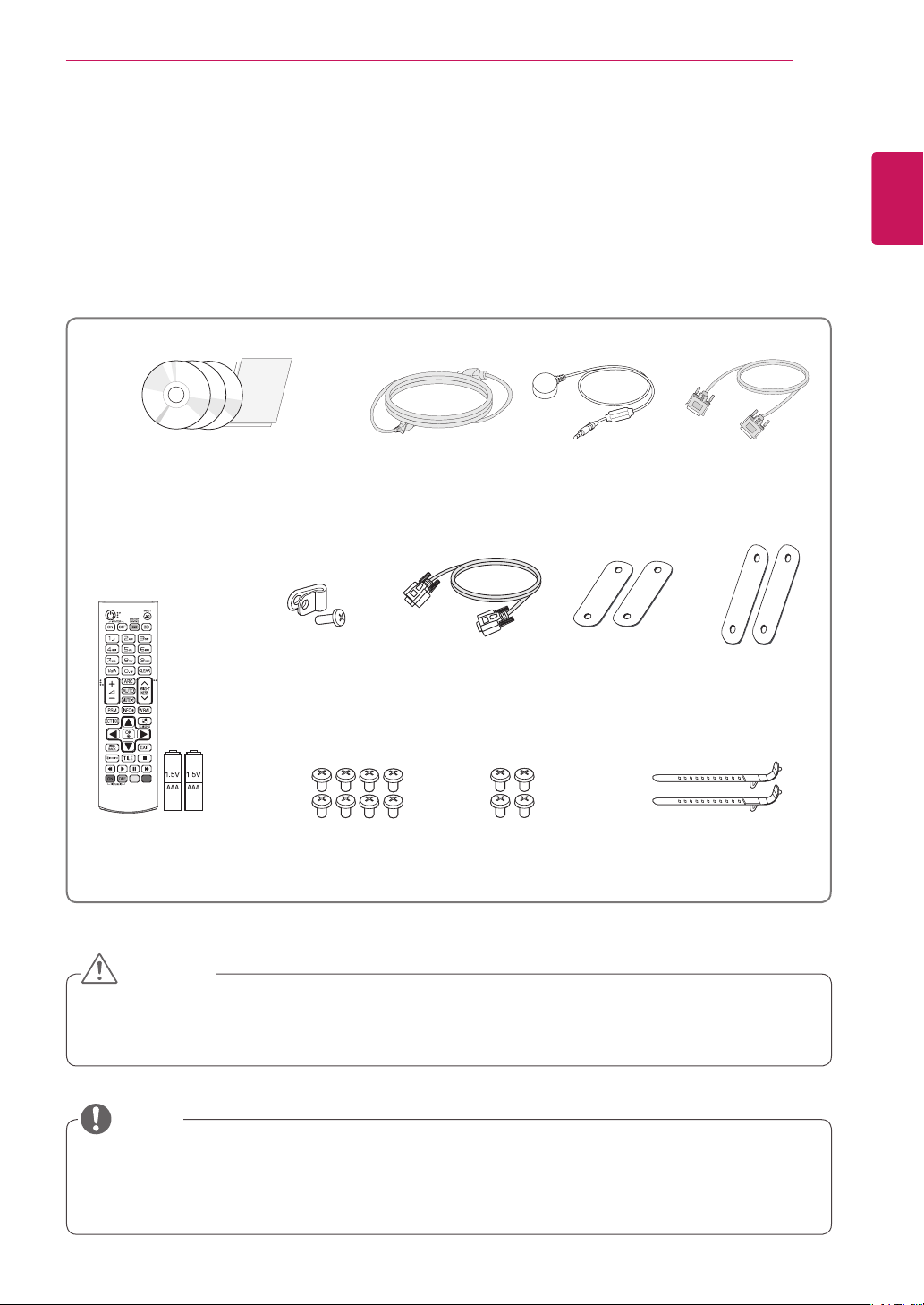
Accessories
Check your product box for the following items. If there are any missing accessories, contact the local
dealer where you purchased your product. The illustrations in this manual may differ from the actual product
and accessories.
CD (Owner's Manual,
SuperSign Elite-c Program/
SuperSign Manual) / Cards
(*SuperSign Elite-w : It may not be
supported depending on the model.)
Power Cord
IR Receiver
DVI Cable
ENGLISH
ENG
Remote Control
and Batteries
Power Cable Holder
M4 x 8L
Screws (8 ea)
RS-232C Cable
M6
Screws (4 ea)
Short Vertical
Tiling Guide
Mounting Cable Tie (2 ea)
(For Cable Arrangement)
(2 ea)
Long Horizontal
Tiling Guide
(2 ea)
CAUTION
Do not use any pirated items to ensure the safety and product life span.
y
Any damages or injuries by using pirated items are not covered by the warranty.
y
NOTE
The accessories supplied with your product may vary depending on the model.
y
Product specifications or contents in this manual may be changed without prior notice due to upgrade
y
of product functions.
ASSEMBLING AND PREPARING
6
ENGLISH
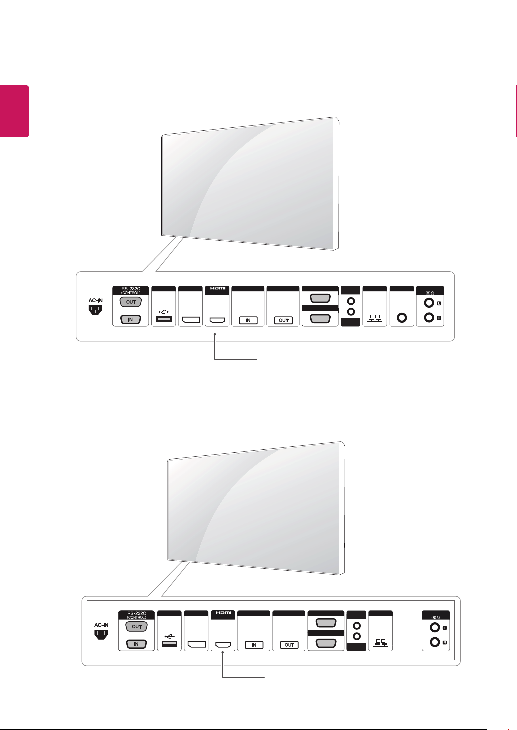
Parts
ENG
< 47WV50BR / 47WV50MS >
RGB
USB DP LAN
/DVI
DVI IN DVI OUT
/COMPONENT OUT
/COMPONENT IN
AUDIO
IN
RGB
REMOTE
CONTROL IN
Connection panel
COMPOSITE
SPEAKER
< 47WV50BS >
USB DP LANDVI IN DVI OUT
/DVI
Connection panel
RGB
/COMPONENT OUT
RGB
/COMPONENT IN
AUDIO
IN
REMOTE
CONTROL IN
SPEAKER
ASSEMBLING AND PREPARING
7
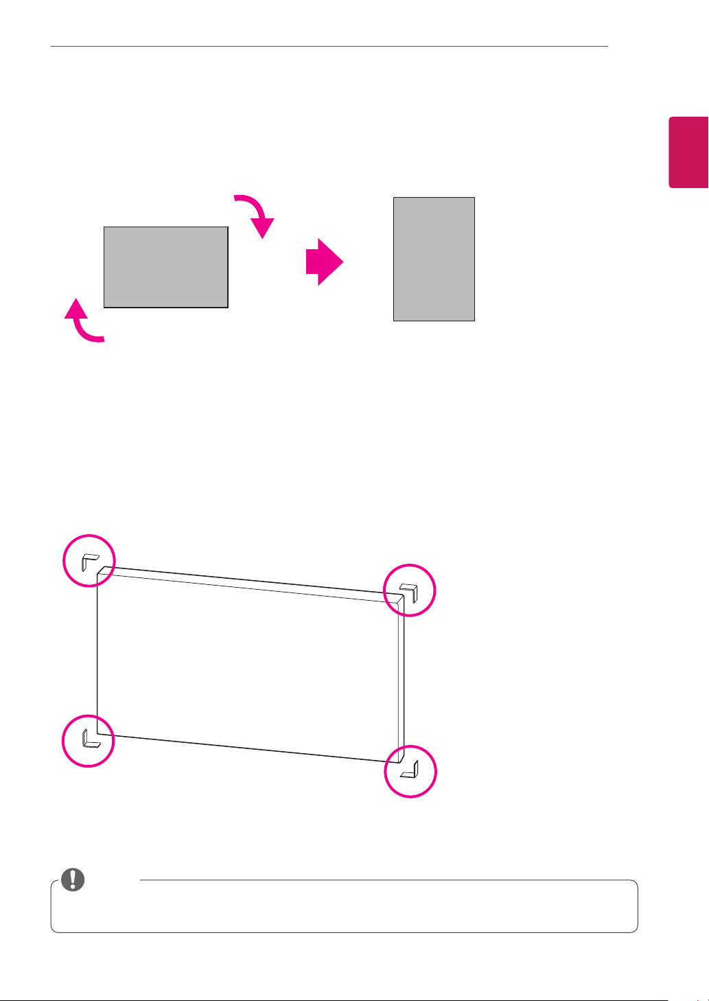
To Install in a Portrait Layout
When installing in a Portrait Layout, rotate the monitor clockwise 90 degrees (when facing the screen).
Remove L-brackets before Installation
Remove the L-brackets from each corner of the monitor before installing it.
ENGLISH
ENG
NOTE
Keep the removed L-brackets and use them when moving the monitor later.
y
ASSEMBLING AND PREPARING
8
ENGLISH
STORAGE METHOD FOR PANEL PROTECTION
ENG
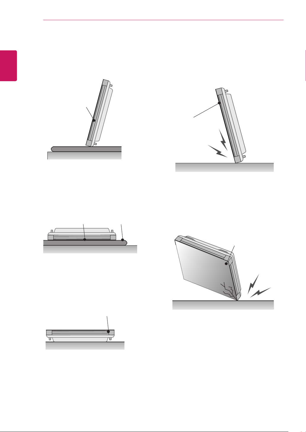
Correct Method Incorrect Method
If the product needs to be set upright, hold both
sides of the product, and tilt backward carefully
for. Do not let the panel not to touch the floor.
Panel
Panel
If the product is tilted onto the bezel, the bottom of
the panel may be damaged.
Panel
When laying down the product, lay a cushion on a
flat floor. Put the product on it with the panel of
the product facing down.
Cushion
Panel
If there is not a cushion available, ensure the floor
is clean and then lay the product down carefully
with the panel facing either upward or downward.
At this time, be careful for objects not to fall on the
panel.
Panel
If the product is tilted onto the edge of the panel,
the panel may be damaged.
ASSEMBLING AND PREPARING
9
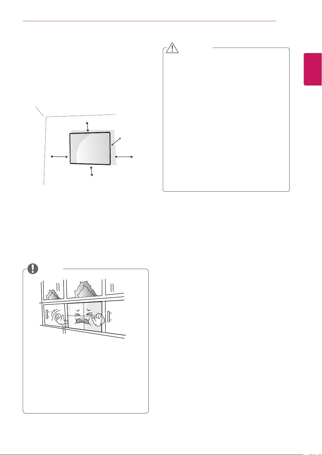
Installing on a Wall
To install the Monitor on a wall (optional),
use the VESA screws provided as accessories to
fasten it.
Please refer to page 12 on How to Mount the Set.
10 cm
20 cm
10 cm
10 cm
Install the monitor at least 10 cm away from the
wall and leave about 10 cm of space at each side
of the monitor to ensure sufficient ventilation.
Use the wall mount plate and screws that comply
with the VESA standard.
10 cm
CAUTION
Disconnect the power cord first, and then
y
move or install the monitor set. Otherwise
electric shock may occur.
If you install the monitor set on a ceiling or
y
slanted wall, it may fall and result in severe
injury.
Do not over tighten the screws as this may
y
cause damage to the monitor set and void
your warranty.
Use the screws and wall mounts that meet
y
the VESA standard. Any damages or injuries
by misuse or using an improper accessory
are not covered by the warranty.
To prevent injury, this apparatus must be
y
securely attached to the wall in accordance
with the instrallation instructions. (This only
pertains to Australia.)
ENGLISH
ENG
NOTE
Do not install the product in a place with
no ventilation (e.g., on a bookshelf or in a
closet) or on a carpet or cushion. If there is
no other option but to mount the product on
the wall, make sure that sufcient ventilation
is provided before installation.
- Failure to do so may result in a re due to
the increase in the internal temperature.
ASSEMBLING AND PREPARING
10
ENGLISH
ENG
(Depending on model)
1
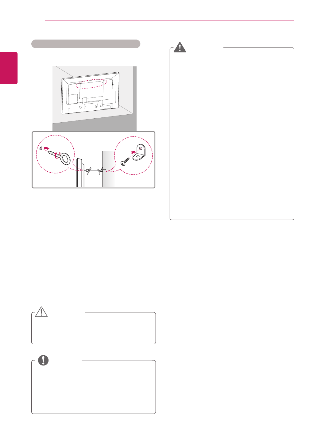
Securing the product to a wall (optional)
Insert and tighten the eye-bolts, or product
brackets and bolts on the back of the product.
- If there are bolts inserted at the eye-bolts
position, remove the bolts first.
WARNING
If a product is not positioned in a sufficiently
y
stable location, it can be potentially
hazardous due to falling. Many injuries,
particularly to children, can be avoided by
taking simple precautions such as:
»Using cabinets or stands recommended
by the manufacturer of the product.
»Only using furniture that can safely
support the product.
»Ensuring the product is not overhanging
the edge of the supporting furniture.
»Not placing the product on tall furniture
(for example, cupboards or bookcases)
without anchoring both the furniture and
the product to a suitable support.
»Not standing the product on cloth or other
materials placed between the product
and supporting furniture.
»Educating children about the dangers of
climbing on furniture to reach the product
or its controls.
Mount the wall brackets with the bolts to the
2
wall.
Match the location of the wall bracket and the
eye-bolts on the rear of the product.
Connect the eye-bolts and wall brackets tightly
3
with a sturdy rope.
Make sure to keep the rope horizontal with the
flat surface.
CAUTION
Make sure that children do not climb on or
y
hang on the product.
NOTE
Use a platform or cabinet that is strong and
y
large enough to support the product securely.
Brackets, bolts, and ropes are optional. You
y
can obtain additional accessories from your
local dealer.
ASSEMBLING AND PREPARING
11
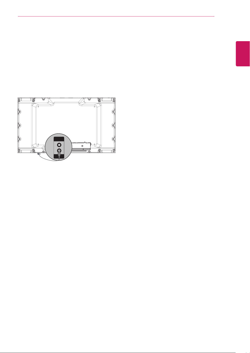
EXTERNAL EQUIPMENT SETUP
IR RECEIVER
This allows a remote control sensor to be placed
in a custom location. Then that display can control
other displays via an RS-232C cable.
AUDIO
IN
REMOTE
CONTROL IN
ENGLISH
ENG
ASSEMBLING AND PREPARING
12
ENGLISH
Tiling Displays
ENG
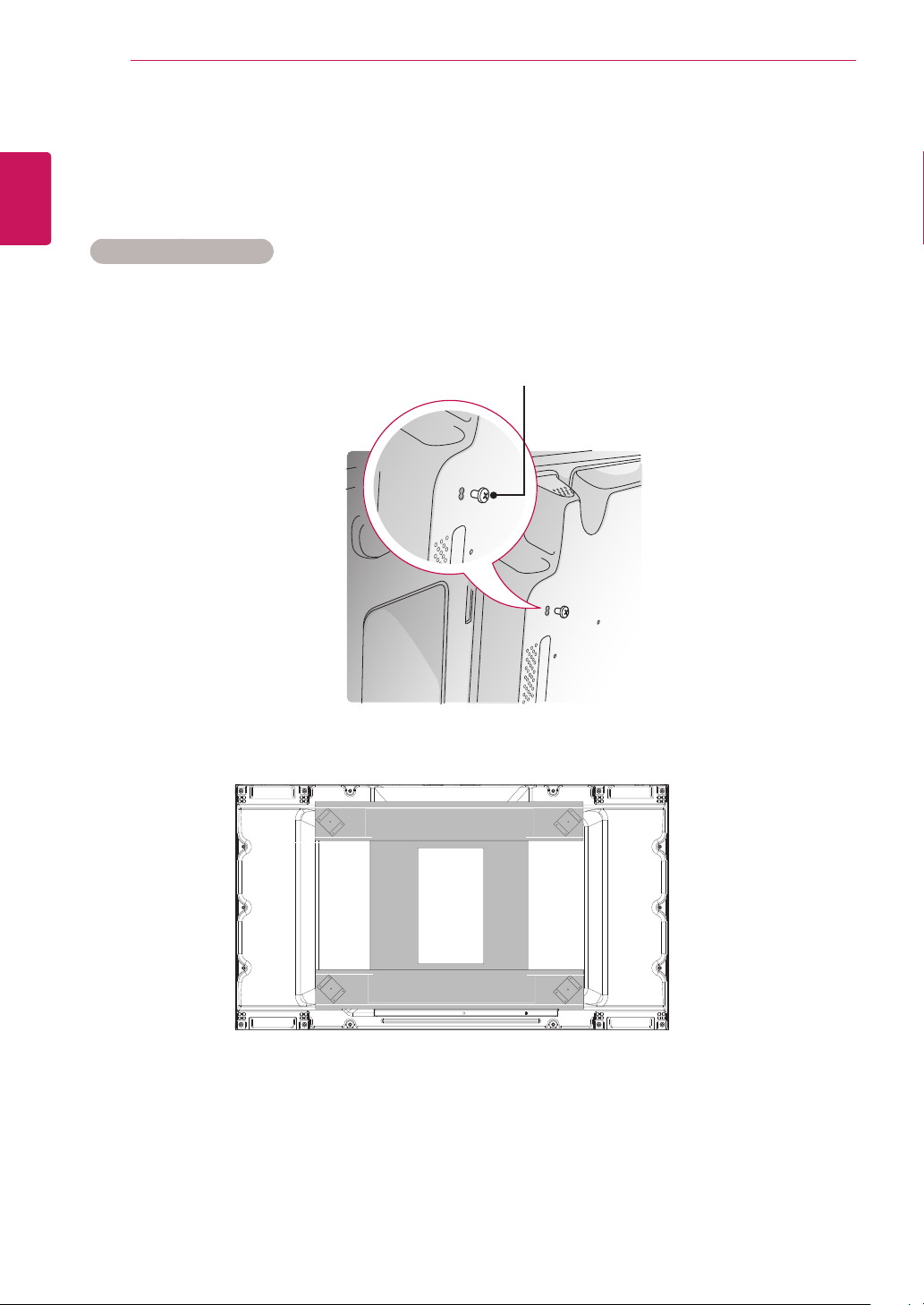
How to Mount the Set
Using the screws for attaching the VESA wall mount, mount the set to the wall mount plate or the wall.
Example of 2 x 2 Tiling
Screws for attaching the
VESA wall mount
<Rear view of the set with the wall mount plate>
ASSEMBLING AND PREPARING
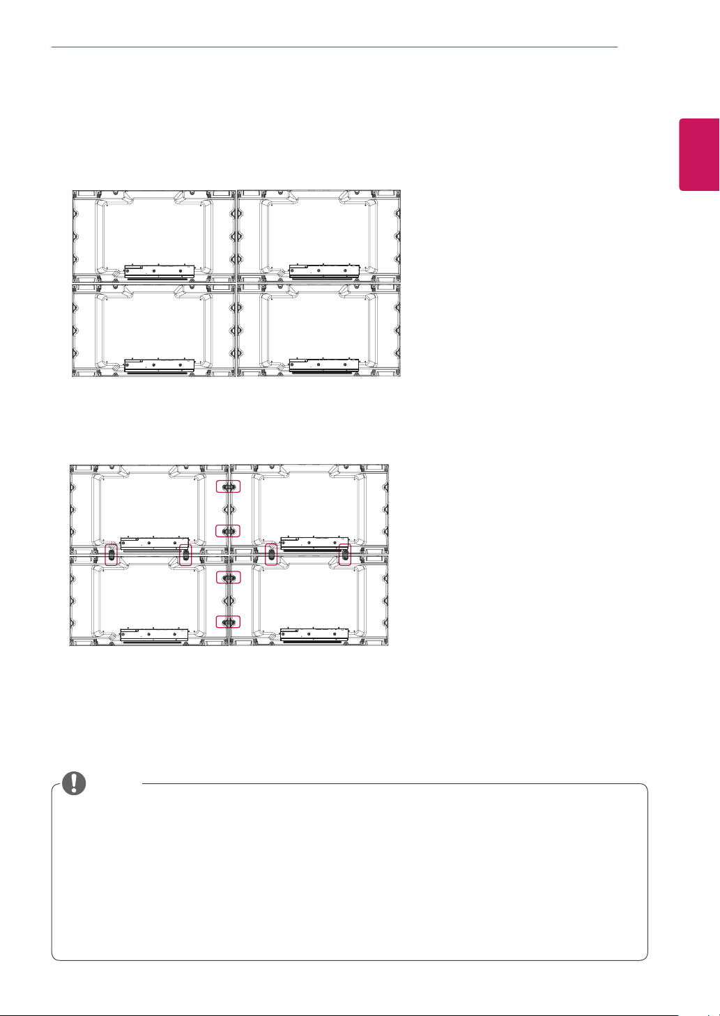
How to Join Sets
1 Join other sets using screws for xing the VESA wall mount in the same way as above.
Set 4 joined to the rest of the sets
(2 x 2 tiling)
2 After joining the sets, use the tiling guide to adjust the gap between the sets.
13
ENGLISH
ENG
3 Now the 2 x 2 tiling is complete.
You can tile in various combinations, such as 3 x 3.
NOTE
The load applied to each set should be supported by the wall mount plate or the wall using a VESA
y
wall mount (600 x 400).
The load applied to each set should be supported by the wall mount plate using a VESA wall mount.
y
(Each set must be firmly mounted to the wall mount plate or the wall.)
You may mount the set without using the tiling guide; this does not affect the performance of the
y
device.
Loosen the screws on the set to install the tiling guides. (The screws are enclosed with the other
y
components in the box, including the tiling guides.)
REMOTE CONTROL
14
ENGLISH
REMOTE CONTROL
ENG
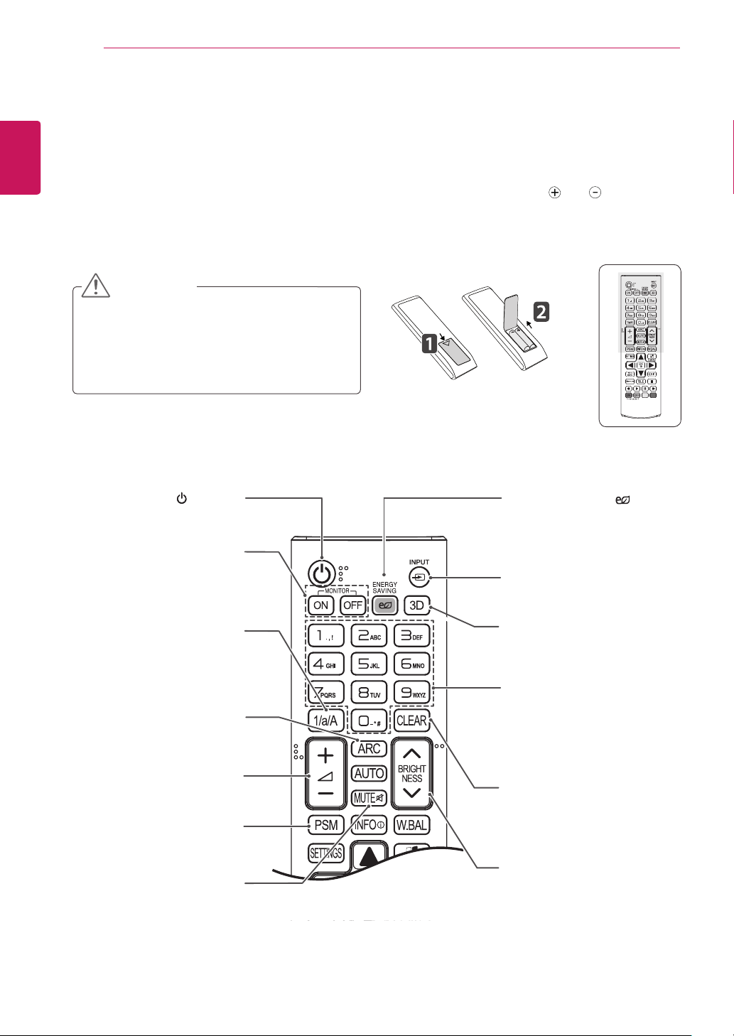
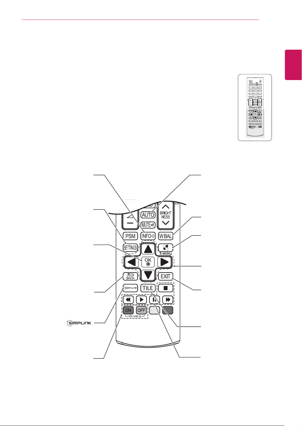
The descriptions in this manual are based on the buttons of the remote control. Please read this manual
carefully and use the monitor set correctly.
To replace batteries, open the battery cover, replace batteries (1.5 V AAA) matching and ends to the
label inside the compartment, and close the battery cover.
To remove the batteries, perform the installation actions in reverse.
CAUTION
Do not mix old and new batteries, as this
y
may damage the remote control.
Make sure to point the remote control to the
y
remote control sensor on the monitor set.
(POWER)
Turns the monitor set on or off.
MONITOR ON
Turn on the monitor.
MONITOR OFF
Turn off the monitor.
ENERGY SAVING( )
Adjusts the brightness of
the screen to reduce energy
consumption.
INPUT
Selects the input mode.
1/a/A Button
Toggles between numerical
and alphabetical.
ARC
Selects the Aspect Ratio
Mode.
Volume Up / Down
Adjusts the volume level.
PSM
Selects the Picture Status
Mode.
MUTE
Mutes all sounds.
3D
This button does not apply to
this model.
Number and Alphabet Buttons
Enters numerical or alphabetical
characters depending on the
setting.
CLEAR
Deletes the entered numerical
or alphabetical character.
BRIGHTNESS Key
Adjust the brightness by
pressing the Up and Down
buttons on the remote control.
In USB mode, the OSD menu
has the Page function to move
to the next file list.
REMOTE CONTROL
15
ENGLISH
ENG
INFO
Displays the input
information.
SETTINGS
Accesses the main menus
or saves your input and exit
menus.
OK
Selects menus or options and
confirms your input.
BACK
Allows the user to move back
one step in user interaction
function.
This button selection is not
applicable.
ⓘ
AUTO
Automatically adjusts picture
position and minimizes image
instability.(RGB input only)
W.BAL
Enters the White Balance
menu.
S.MENU
(SuperSign Menu Key)
This button does not apply to
this model.
Navigation Buttons
Scrolls through menus or
options.
EXIT
Clears all on-screen displays
and returns to Monitor set
viewing from any menu.
TILE
Selects the TILE Mode.
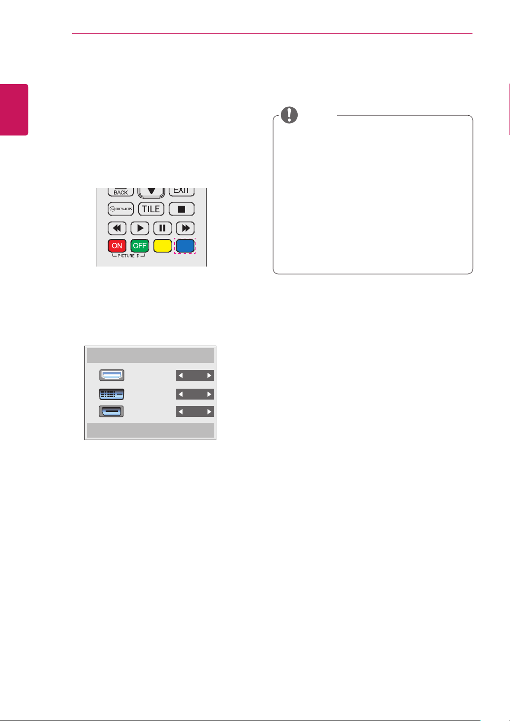
ID ON/OFF
When the number of Picture
ID is equal to Set ID you can
control the monitor which
you want in the multi display
condition.
USB Menu control buttons
Controls media playback.
REMOTE CONTROL
16
ENGLISH
Displaying the Device Name Connected to an Input Port
ENG
Display which devices are connected to which
external input ports.
1 Access the Input list screen and press the blue
2 You can assign an input label for every input
(input label) button on the remote control.
except USB.
Input Label
NOTE
External inputs supported: HDMI, DVI-D,
y
Display Port
Labels available: PC, DTV
y
The input labels are displayed on the Input
y
Label screen or at the top left of the screen
when you change the external input setting.
For DTV/PC-compatible signals, such as
y
1080p 60 Hz, the screen settings may
change according to the input label. The Just
Scan option is available if a PC is connected
as an external device.
HDMI
DVI-D
Display Port
Close
USING THE MONITOR SET
AUDIO
IN
REMOTE
CONTROL IN
RGB
/COMPONENT OUT
RGB
/COMPONENT IN
AUDIO
IN
REMOTE
CONTROL IN
DVI IN
17
USING THE MONITOR SET
Connecting to a PC
Your Monitor set supports the Plug & Play* feature.
* Plug & Play: A PC will have a built-in driver for
the monitor, no extra software is needed.
NOTE
It is recommended to use the monitor set
y
with the HDMI connection for the best image
quality.
To comply with the specifications of the
y
product, use a shielded interface cable with
ferrite core, such as a D-sub 15-pin cable
and DVI/HDMI cable.
If you turn the monitor set on when the set
y
becomes cold, the screen may flicker. This
is normal.
Some red, green, or blue spots may appear
y
on the screen. This is normal.
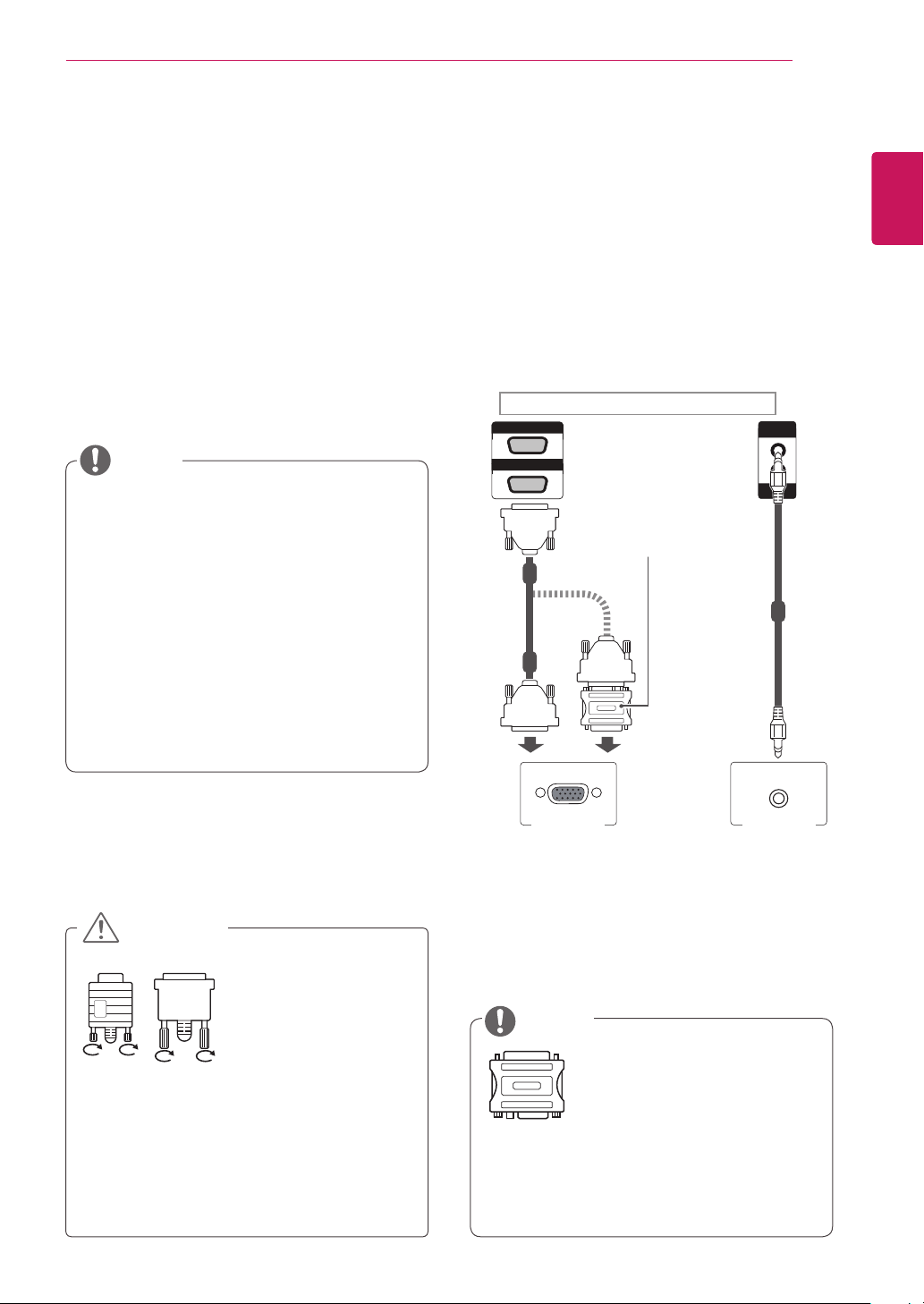
RGB Connection
Transmits the analog video signal from your PC to
the monitor set. Connect the PC and the Monitor
set with the 15-pin signal cable as shown the
following illustrations.
Select RGB input.
included)
ENGLISH
ENG
Back of the product.
Macintosh Adapter
(not included)
(not
(not included)
CAUTION
Connect the signal
y
input cable and tighten
it by turning the screws
clockwise.
Do not press the screen with your finger for
y
a long time as this may result in temporary
distortion on the screen.
Avoid displaying a fixed image on the
y
screen for a long period of time to prevent
image burn. Use a screensaver if possible.
PC/MAC
PC
NOTE
Use the standard Macintosh
y
adapter since an incompatible
ad ap ter is av ai la bl e in the
marke t. (Diffe rent sign aling
system)
Apple computers may require an adapter to
y
connect to this monitor. Call or visit their web
site for more information.
USING THE MONITOR SET
AUDIO
IN
REMOTE
CONTROL IN
IN/DVI
DP
DVI IN
AUDIO
IN
REMOTE
CONTROL IN
IN/DVI
DP
AUDIO
IN
REMOTE
CONTROL IN
18
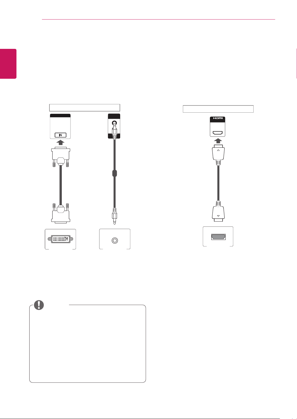
DVI Connection
ENGLISH
ENG
Transmits digital video signal from your PC to
the monitor set. Connect the PC and the monitor
set with the DVI cable as shown the following
illustrations.
Select DVI input.
Back of the product.
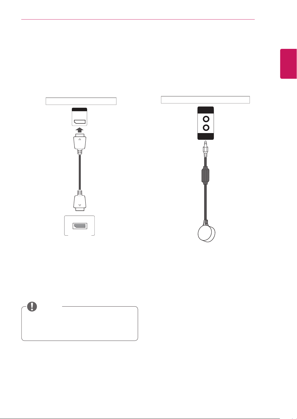
HDMI Connection
Transmits digital video and audio signals from your
PC to the monitor set. Connect the PC and the
monitor set with the HDMI cable as shown in the
following illustrations.
Select HDMI input.
Back of the product.
(not included)
(not included)
PC PC
NOTE
Use a High Speed HDMI™ Cable.
y
Please check the PC environment if you
y
PC
cannot hear the sound in HDMI mode.
Some PCs require you to manually change
the default audio output to HDMI.
If you want to use HDMI-PC mode, you
y
must set the input label to PC mode.
When HDMI PC is used, a compatiblity
y
problem could occur.
USING THE MONITOR SET
AUDIO
IN
REMOTE
CONTROL IN
DP
AUDIO
IN
REMOTE
CONTROL IN
19
Display Port Connection
Transmits digital video and audio signals from
your PC to the Monitor. Connect the PC and the
Monitor with the Display Port cable as shown in
the following illustrations.
Select Display Port input source.
Back of the product.
(not included)
IR Receiver Connection
Allows the use of IR receiver extension.
Back of the product.
ENGLISH
ENG
PC
PC
NOTE
Sound may not be available depending on
y
the DP version of your PC.
USING THE MONITOR SET
20
ENGLISH
Adjusting the Screen
ENG
Selecting an Image Mode
Display images in its optimized settings by
selecting one of the preset image modes.
1
2
3
4
5
Press SETTINGS to access the main menus.
Press the navigation buttons to scroll to
PICTURE and press OK.
Press the navigation buttons to scroll to
Picture Mode and press OK.
Press the navigation buttons to scroll to an
image mode you want and press OK.
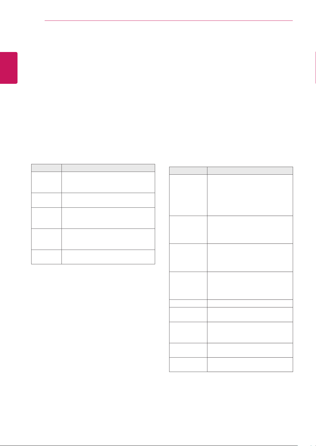
Mode Description
Vivid Adjusts the video image for the retail
environment by enhancing the contrast,
brightness, color, and sharpness.
Standard Adjusts the image for the normal
environment.
Cinema Optimizes the video image for a cinematic
look to enjoy movies as if you are in a
movie theater.
Sport Optimizes the video image for high and
dynamic actions by emphasizing primary
colors such as white, grass, or sky blue.
Game Optimizes the video image for a fast
gaming screen such as PCs or games.
When you are finished, press EXIT.
When you return to the previous menu, press
BACK.
Customizing Image Options
Customize basic and advanced options of each
image mode for the best screen performance.
Press SETTINGS to access the main menus.
1
Press the navigation buttons to scroll to
2
PICTURE and press OK.
Press the navigation buttons to scroll to
3
Picture Mode and press OK.
Press the navigation buttons to scroll to an
4
image mode you want and press OK.
Select and adjust following options, and then
5
press OK.
Option Description
Backlight Adjusts the brightness of the screen
by controlling the LCD backlight. If
you decrease the brightness level,
the screen becomes darker and the
power consumption will be reduced
without any video signal loss.
Contrast Increases or decreases the gradient
of the video signal. You may use
Contrast when the bright part of the
picture is saturated.
Brightness Adjusts the base level of the signal in
the picture. You may use Brightness
when the dark part of the picture is
saturated.
Sharpness Adjusts the level of crispness in the
edges between the light and dark
areas of the picture. The lower the
level, the softer the image.
Color Adjusts intensity of all colors.
Tint Adjusts the balance between red and
green levels.
Color Temp. Set to warm to enhance hotter Colors
such as red, or set to cool to make
picture bluish.
Advanced
Control
Picture Reset Restores the options to the default
Customizes the advanced options.
Refer to the Advanced image options.
setting.
When you are finished, press EXIT.
6
When you return to the previous menu, press
BACK.
USING THE MONITOR SET
21
Customizing PC Display Options
Customize options of each image mode for the
best image quality.
This function works in the following mode:
y
RGB [PC] mode.
Press SETTINGS to access the main menus.
1
Press the navigation buttons to scroll to
2
PICTURE and press OK.
Press the navigation buttons to scroll to Screen
3
and press OK.
Select and adjust following options, and then
4
press OK.
Option Description
Resolution Selects a proper resolution.
Auto
Config.
Position/
Size/Phase
Reset Restores the options to the default
Sets to adjust the screen position, clock,
and phase automatically. The displayed
image may be unstable for a few seconds
while the configuration is in progress.
Adjusts the options when the picture is
not clear, especially when characters are
shaky, after the auto configuration.
setting.
Adjusting the Sound
Selecting an Sound Mode
Play the sound in its optimized settings by
selecting one of the preset sound modes.
Press SETTINGS to access the main menus.
1
Press the navigation buttons to scroll to AUDIO
2
and press OK.
Press the navigation buttons to scroll to Sound
3
Mode and press OK.
Press the navigation buttons to scroll to a
4
sound mode you want and press OK.
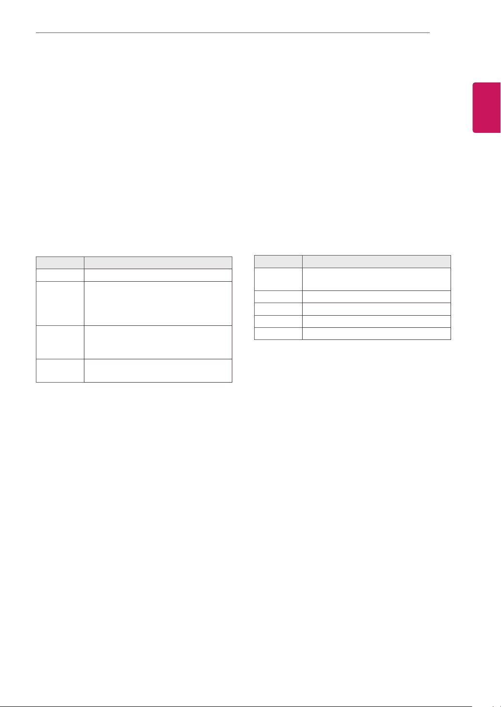
Mode Description
Standard Select when you want standard-quality
sound.
Music Select when you listen to music.
Cinema Select when you watch movies.
Sports Select when you watch sports events.
Game Select when you play games.
When you are finished, press EXIT.
5
When you return to the previous menu, press
BACK.
ENGLISH
ENG
When you are finished, press EXIT.
5
When you return to the previous menu, press
BACK.
USING THE MONITOR SET
22
Customizing Sound Options
ENGLISH
ENG
Customize options of each sound mode for the
best sound quality.
1
2
3
4
5
Press SETTINGS to access the main menus.
Press the navigation buttons to scroll to AUDIO
and press OK.
Press the navigation buttons to scroll to Sound
Mode and press OK.
Press the navigation buttons to scroll to a
sound mode you want and press OK.
Select and adjust following options, and then
press OK.
Option Description
Infinite
Sound
Treble Increases the intensity of the high
Bass Increases the intensity of the low
Reset Resets the sound mode to the default
LG's Infinity Sound option provides 5.1
channel stereo sound quality from two
speakers.
frequency part of audio.
frequency part of audio.
setting.
Using Additional Options
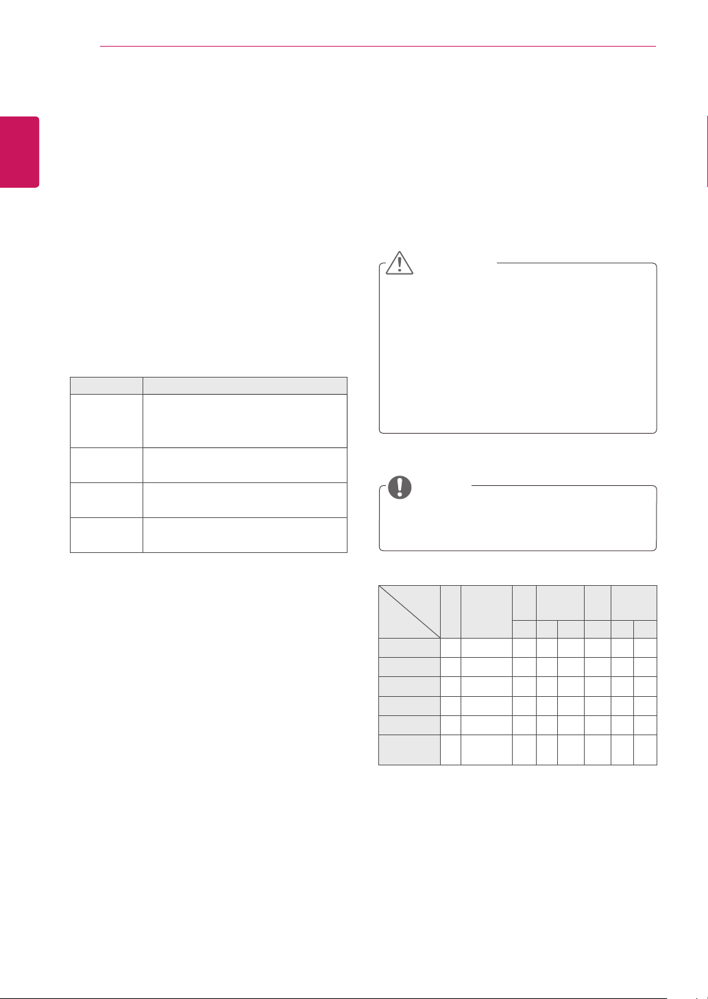
Adjusting Aspect Ratio
Resize the image to view the image at its optimal
size by pressing ARC while you are watching
Monitor set.
CAUTION
If a fixed image displays on the screen for a
y
long period of time, it could be imprinted and
become a permanent disfigurement on the
screen. This is image burn or burn-in and not
covered by the warranty.
If the aspect ratio is set to 4:3 for a long
y
period of time, image burn may occur on the
letterboxed area of the screen.
NOTE
You can also change the image size by
y
accessing the main menus.
When you are finished, press EXIT.
6
When you return to the previous menu, press
BACK.
MODE
ARC
16:9
Just Scan
1:1
4:3
Zoom
Cinema
Zoom
AV Component RGB Display
PC DTV PC PC DTV PC
o o o o o o o o
x o x o x x o x
x x o x o o x o
o o o o o o o o
o o x o x x o x
o o x o x x o x
DVI-D HDMI
Port
USING THE MONITOR SET
23
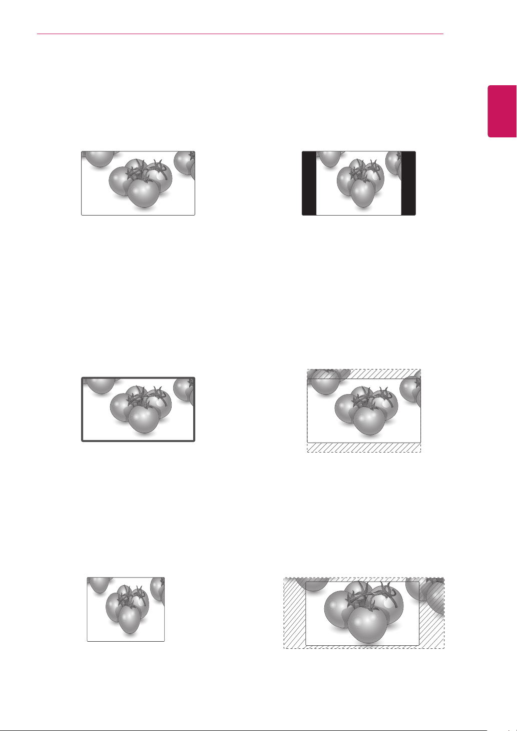
- 16:9 : This selection will allow you to adjust the
picture horizontally, in linear proportion, to fill the
entire screen(useful for viewing 4:3 formatted
DVDs).
- Just Scan : This Selection will allow you view
the picture of best quality without loss of original
picture in high resolution image. Note: If there is
noise in original Picture, You can see the noise
at the edge.
- 4:3 : This selection will allow you to view a
picture with an original 4:3 aspect ratio, black
bars will appear on both the left and right of the
screen.
- Zoom : This selection will allow you to view the
picture without any alteration, while filling the
entire screen. However, the top and bottom of
the picture will be cropped.
ENGLISH
ENG
Just Scan
- 1:1 : The aspect ratio is not adjusted from the
original. (Only Display Port PC, HDMI PC,
DVI-D PC, RGB PC)
- Cinema Zoom : Choose Cinema Zoom when
you want to enlarge the picture in correct
proportion. Note: When enlarging or reducing
the picture, the image may become distorted.
24
Using the Input List
ENGLISH
ENG
1
2
USING THE MONITOR SET
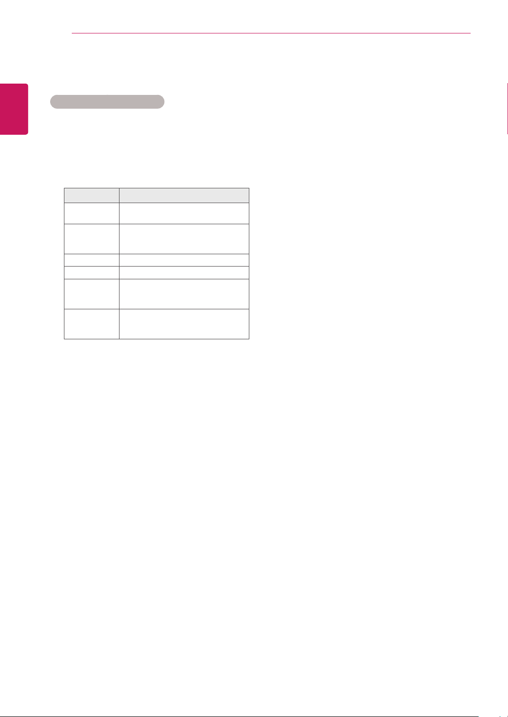
Selecting an Input Source
Press INPUT to access the input source list.
Press the navigation buttons to scroll to one of
the input sources and press OK.
Input source Description
AV Watch video from a VCR or other
external devices.
Component Watch the content from a DVD or
other external devices, or through a
digital set-top box
RGB View a PC display on the screen
DVI-D View a PC display on the screen
HDMI Watch contents from a PC, DVD
of Digital set-top box other high
definition devices
Display Port Watch contents in a PC, DVD
of Digital set-top box other high
definition devices
ENTERTAINMENT
25
ENTERTAINMENT
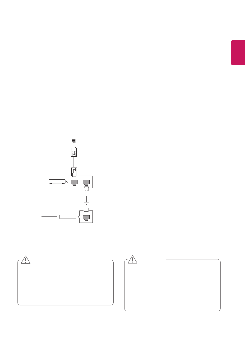
Connecting to a Wired Network
Connect the display to a local area network (LAN)
via the LAN port as shown on the following illustration and set up the network settings.
Only supports wired network connection.
After making a physical connection, a small
number of networks may require the display network settings to be adjusted. For most networks,
the display will connect to automatically without
any adjustments.
For detail information, contact your internet provider or router manual.
LAN
Router
Router
LAN WAN
ENGLISH
ENG
To set up the network settings: (Even if your display has already connected automatically, running
setup again will not harm anything),
1 Press SETTINGS to access the main menus.
2 Press the navigation buttons to scroll to NET-
WORK and press OK.
3 Press the navigation buttons to select Network
Setting and press OK.
4 If you already set Network Setting, select
Resetting. The new connection settings resets
the current network settings.
5 Select IP Auto Setting or IP Manual Setting.
- If selecting IP Manual Setting, press the
navigation and number buttons. IP addresses
will need to be input manually.
- IP Auto Setting: Select this if there is a
DHCP server (Router) on the local area network (LAN) via wired connection, the display
will automatically be allocated an IP address.
If you’re using a broadband router or broadband modem that has a DHCP (Dynamic
Host Configuration Protocol) server function.
The IP address will automatically be determined.
@
Internet
Internet
Cable modem
Cable modem
ETHERNET
CAUTION
y Do not connect a modular phone cable to
the LAN port.
y Since there are various connection meth-
ods, please follow the specifications of your
telecommunication carrier or internet service
provider.
6 When you are finished, press EXIT.
CAUTION
y Network setting menu will not be avail-
able until the display connected to physical
network.
y Since there are various connection meth-
ods, please follow the specifications of your
telecommunication carrier or internet service
provider.
ENTERTAINMENT
26
ENGLISH
ENG
NOTE
y If you want to access the Internet directly on
your display, the Internet connection should
always be on.
y If you cannot access the Internet, check
the network conditions from a PC on your
network.
y When you use Network Setting, check the
LAN cable or check if DHCP in the router is
turned on.
y If you do not complete the network settings,
the network may not work properly.
Tips for Network Setting
y Use a standard LAN cable with this display.
Cat5 or better with a RJ45 connector.
y Many network connection problems during set
up can often be fixed by re-setting the router
or modem. After connecting the display to the
network, quickly power off and/or disconnect
the power cable of the network router or cable
modem. Then power on and/or connect the
power cable again.
y Depending on the Internet service provider
(ISP), the number of devices that can receive
Internet service may be limited by the applicable terms of service. For details, contact your
ISP.
y LG is not responsible for any malfunction of the
display and/or the Internet connection feature
due to communication errors/malfunctions associated with your Internet connection, or other
connected equipment.
y LG is not responsible for problems within your
internet connection.
y You may experience undesired results if the
network connection speed does not meet the
requirements of the content being accessed.
y Some internet connection operations may not
be possible due to certain restrictions set by
the Internet service provider (ISP) supplying
your Internet connection.
y Any fees charged by an ISP including, without
limitation, connection charges are your responsibility.
y A 10 Base-T or 100 Base-TX LAN port is
required when using a wired connection to this
display. If your internet service does not allow
for such a connection, you will not be able to
connect the display.
y A DSL modem is required to use DSL service
and a cable modem is required to use cable
modem service. Depending on the access
method of and subscriber agreement with your
ISP, you may not be able to use the internet
connection feature contained in this display or
you may be limited to the number of devices
you can connect at the same time. (If your ISP
limits sub-scription to one device, this display
may not be allowed to connect when a PC is
already connected.)
y The use of a “Router” may not be allowed or its
usage may be limited depending on the policies and restrictions of your ISP. For details,
contact your ISP directly.
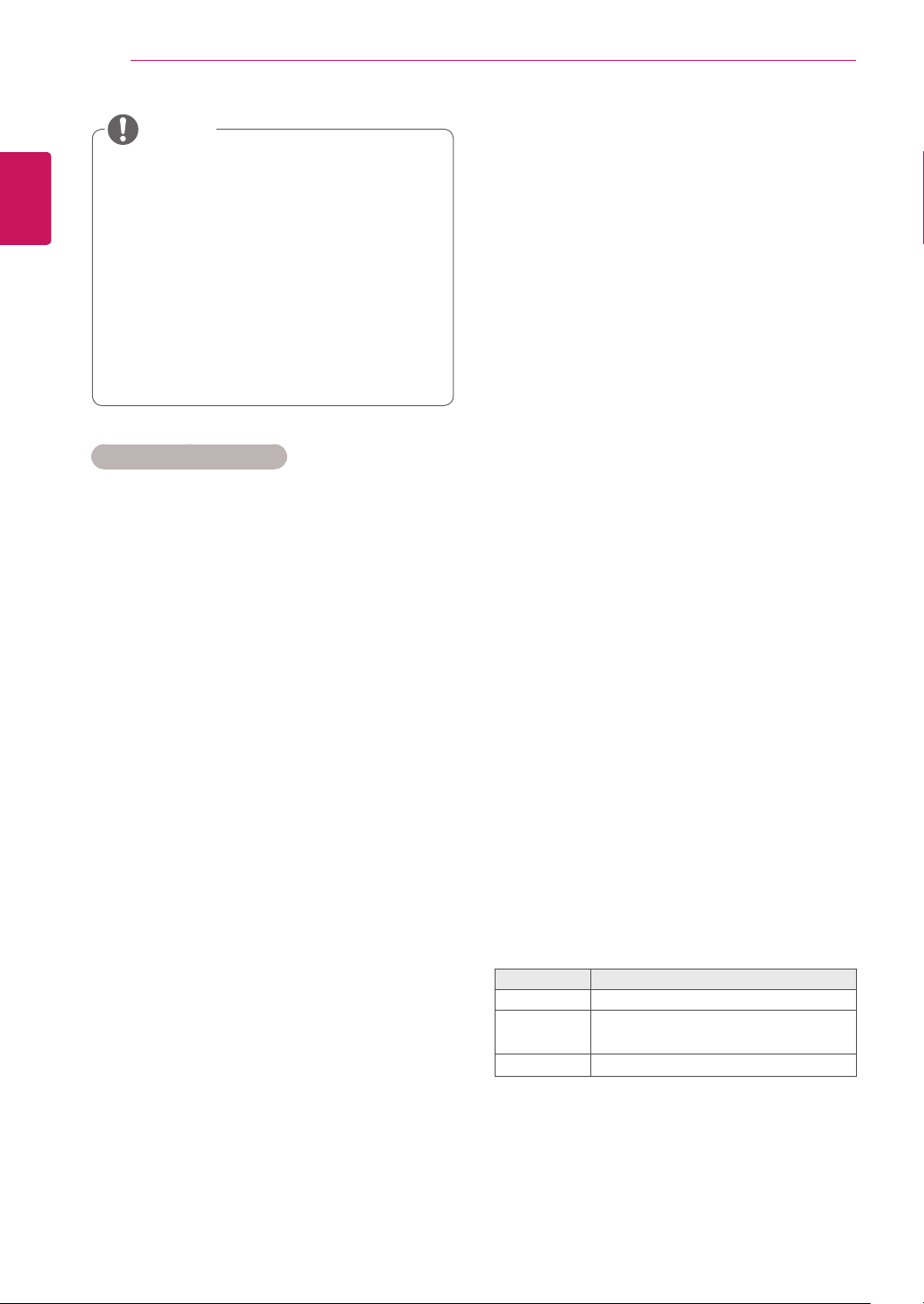
Network Status
1 Press SETTINGS to access the main menus.
2 Press the navigation buttons to scroll to
NETWORK and press OK.
3 Press the navigation buttons to select
Network Status.
4 Press OK to check the network status.
5 When you are finished, press EXIT.
Option Description
Setting Return to the network setting menu.
Test
Close Return to the previous menu.
Test the current network status after set-
ting the network.
 Loading...