

LG 47WV30MS-B, 47WV30BR-B User guide

ENGLISH
ENG
OWNER’S MANUAL
MONITOR SIGNAGE
Please read this manual carefully before operating your set and retain
it for future reference.
MONITOR SIGNAGE MODELS
47WV30MS
47WV30BR
47WV30BS
47WV30-BAAM
47WV30-BAAL
www.lg.com

TABLE OF CONTENTS
2
ENGLISH
CONTENTS
ENG
4 LICENSE
5 ASSEMBLING AND
5 Unpacking
6 Parts
7 To install in a Portrait Layout
7 Remove L-brackets before Installation
8 Moving Handles
8 - Moving the device in a vertical position
8 - Moving the device in a horizontal
9 STORAGE METHOD FOR PANEL
9 - Correct Method
9 - Incorrect Method
10 Installing on a wall
11 EXTERNAL EQUIPMENT SETUP
11 - IR RECEIVER
12 Tiling Displays
12 - How to Join Sets - Installing Set 1
13 - How to Join Sets - Installing Set 2
14 - How to Join Sets - Installing Set 3
15 - How to Join Sets - Installing Set 4
16 Inserting the Cable Holder
17 REMOTE CONTROL
19 Displaying the device name connected to
20 Picture ID
21 USING THE MONITOR SET
21 Connecting to a PC
21 - RGB connection
22 - DVI connection
22 - HDMI connection
23 - Audio connection
PREPARING
position
PROTECTION
an input port
23 - IR Receiver connection
24 Adjusting the screen
24 - Selecting an image mode
24 - Customizing image options
25 - Customizing PC display options
25 Adjusting the sound
25 - Selecting an sound mode
26 - Customizing sound options
26 Using additional options
26 - Adjusting aspect ratio
28 ENTERTAINMENT
28 - Connecting to a wired network
29 - Network Status
30 - Connecting USB storage devices
31 - Browsing files
32 - Viewing movies
36 - Viewing photos
39 - Listening to music
41 - DivX® VOD Guide
43 CUSTOMIZING SETTINGS
43 Accessing main menus
44 - PICTURE settings
47 - AUDIO settings
48 - TIME settings
49 - OPTION settings
53 - NETWORK settings
54 MAKING CONNECTIONS
55 Connecting to a HD receiver, DVD or
VCR player
55 - HDMI connection
55 - DVI - HDMI connection
56 - Component connection
56 - AV connection (Only 47WV30BR and
47WV30MS)
57 Connecting to the LAN
57 - LAN connection
57 Connecting to a USB
58 Daisy Chain Monitors
58 - RGB Cable
58 - DVI Cable
59 TROUBLESHOOTING
62 SPECIFICATIONS
64 RS-232 CONTROL
TABLE OF CONTENTS
3
ENGLISH
ENG
NOTE
The following three phenomena may occur due to the characteristics of the Super Narrow Bezel
y
LCD. They are not related to the display's performance.
1. The edges of the screen may become darker or shadows may appear.
2. Light leakage may occur depending on the viewing angle.
3. Some components such as the guide boss or clip may be visible on the edges of the screen.

4
LICENSE
ENGLISH
LICENSE
ENG
A different license is supported depending on the model. Visit www.lg.com for more information on the
license.
HDMI, the HDMI logo and High-Definition Multimedia Interface are trademarks or
registered trademarks of HDMI Licensing LLC.
ABOUT DIVX VIDEO: DivX® is a digital video format created by DivX, LLC, a
subsidiary of Rovi Corporation. This is an official DivX Certified® device that
plays DivX video. Visit divx.com for more information and software tools to
convert your files into DivX videos.
ABOUT DIVX VIDEO-ON-DEMAND: This DivX Certified® device must be
registered in order to play purchased DivX Video-on-Demand (VOD) movies.
To obtain your registration code, locate the DivX VOD section in your device
setup menu. Go to vod.divx.com for more information on how to complete your
registration.
DivX Certified® to play DivX® video up to HD 1080p, including premium content.
DivX®, DivX Certified® and associated logos are trademarks of Rovi Corporation
or its subsidiaries and are used under license.
Covered by one or more of the following U.S. patents: 7,295,673; 7,460,668;
7,515,710; 7,519,274
Manufactured under license from Dolby Laboratories. “Dolby” and the double-D
symbol are trademarks of Dolby Laboratories.
ASSEMBLING AND PREPARING
5
ASSEMBLING AND PREPARING
Unpacking
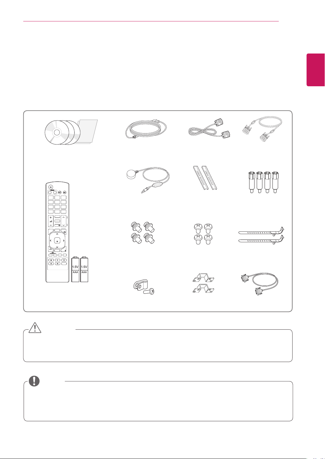
Check your product box for the following items. If there are any missing accessories, contact the local
dealer where you purchased your product. The illustrations in this manual may differ from the actual product
and accessories.
RGB Cable
M6 Screw
For VESA mount
bracket
M4 Screw
For U bracket
Cable holder
For cable
arrangement
CD (Owner's Manual, SuperSign
Program, SuperSign Manual) /
Card
POWER
INPUT
ENERGY
MONITOR
OFF
ON
SAVING
. , !ABCDEF
GHIJKLMNO
PQRSTUV
WXYZ
1/a/A
CLEAR
- * #
MARK
ARC
P
A
BRIGHT
PSM
G
NESS
E
MUTE
AUTO
S.MENU
MENU
OK
EXIT
BACK
TILE
ID
OFF
ON
Power Cord DVI Cable
IR Receiver Guide bracket
M4 x 10L Screw
For guide bracket
ENGLISH
ENG
Remote control and Batteries
Power cable holder U bracket RS-232C Cable
CAUTION
Do not use any pirated items to ensure the safety and product life span.
y
Any damages or injuries by using pirated items are not covered by the warranty.
y
NOTE
The accessories supplied with your product may vary depending on the model.
y
Product specifications or contents in this manual may be changed without prior notice due to upgrade
y
of product functions.
ASSEMBLING AND PREPARING
6
ENGLISH
Parts
ENG
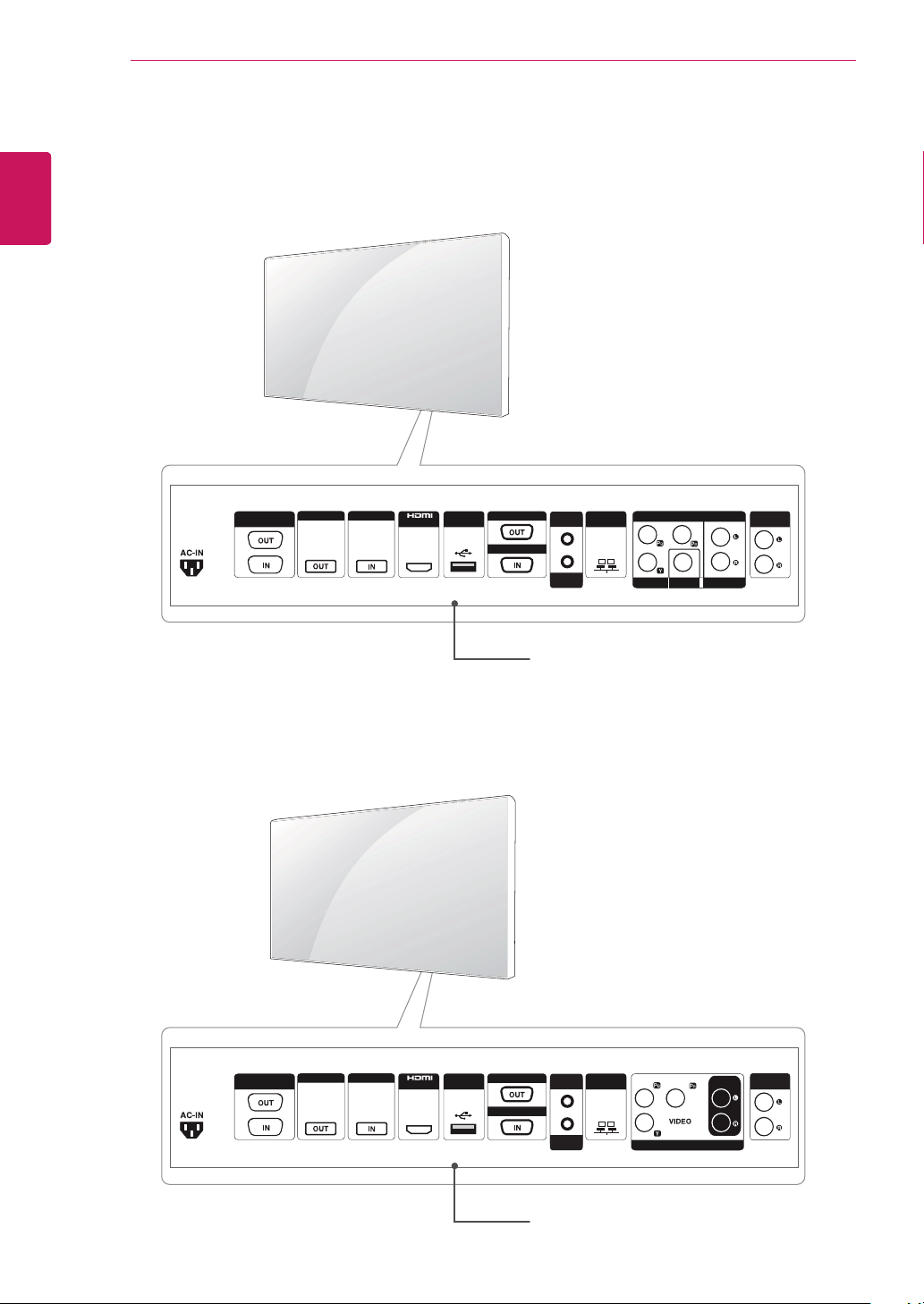
< 47WV30MS/47WV30BR >
RS-232C
(CONTROL)
DVI OUT DVI IN
RGB OUT
USB LAN
/DVI
RGB IN
AUDIO
(RGB/DVI)
REMOTE
CONTROL IN
COMPONENT IN
VIDEO AV IN AUIDO
SPEAKER
(8Ω)
Connection panel
< 47WV30BS/47WV30-BAAM/47WV30-BAAL >
RS-232C
(CONTROL)
DVI OUT DVI IN
RGB OUT
USB LAN
/DVI
RGB IN
AUDIO
(RGB/DVI)
REMOTE
CONTROL IN
COMPONENT IN
AUDIO
SPEAKER
(8Ω)
Connection panel
ASSEMBLING AND PREPARING
7
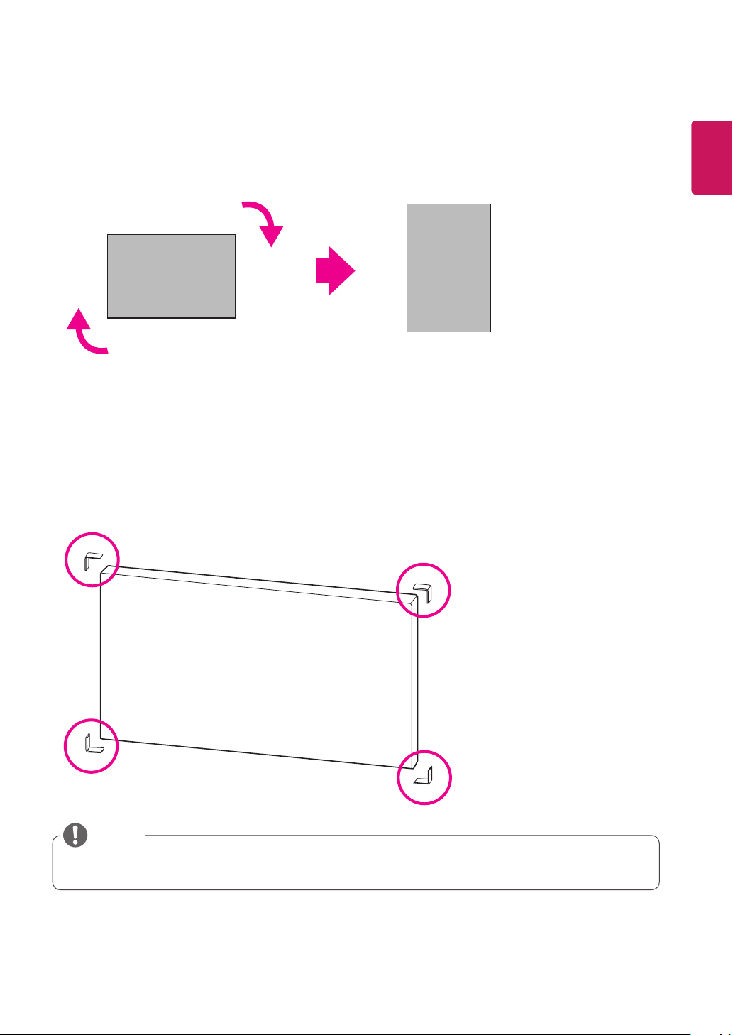
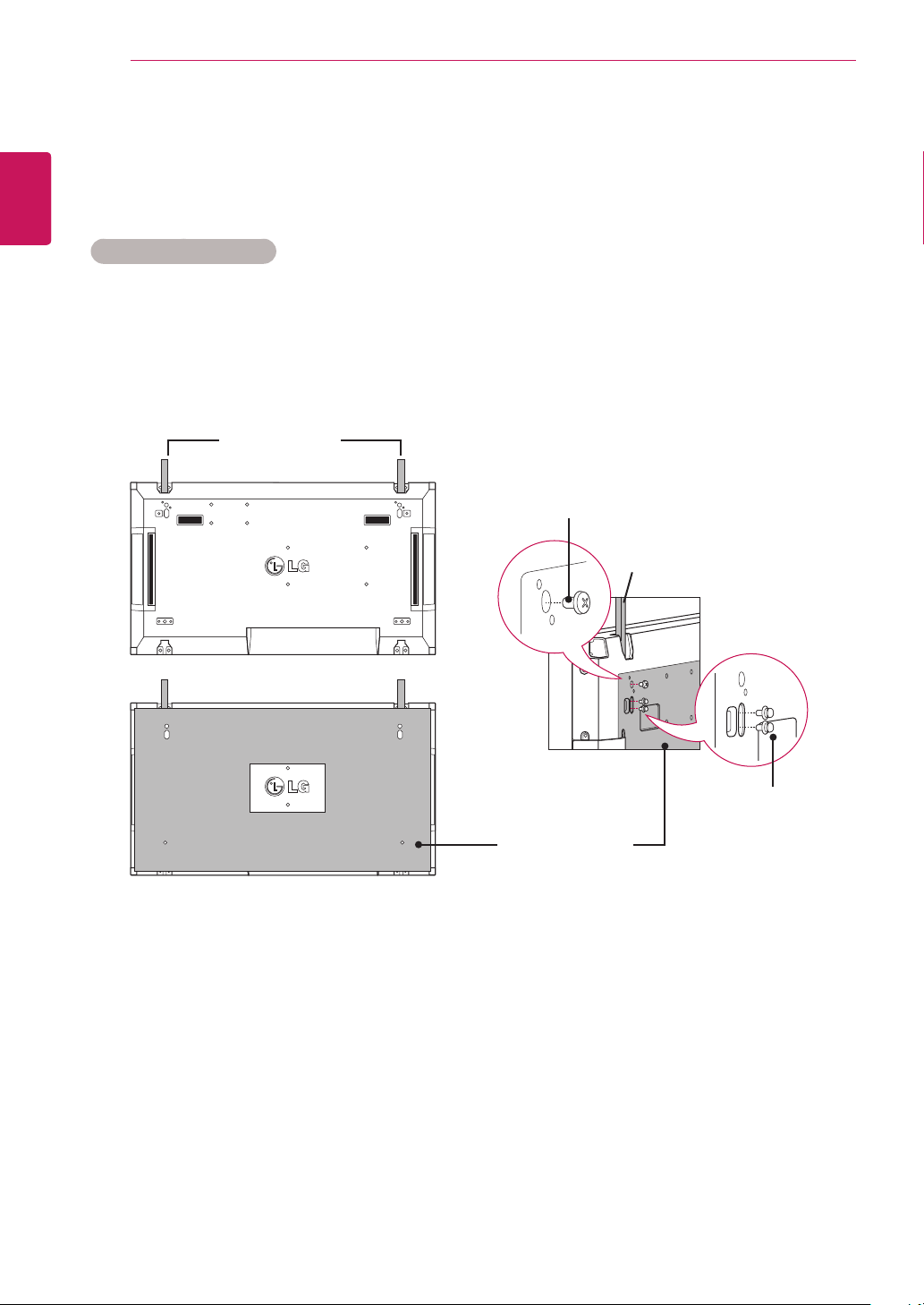
To install in a Portrait Layout
When installing in a Portrait Layout, rotate the monitor clockwise 90 degrees (when facing the screen).
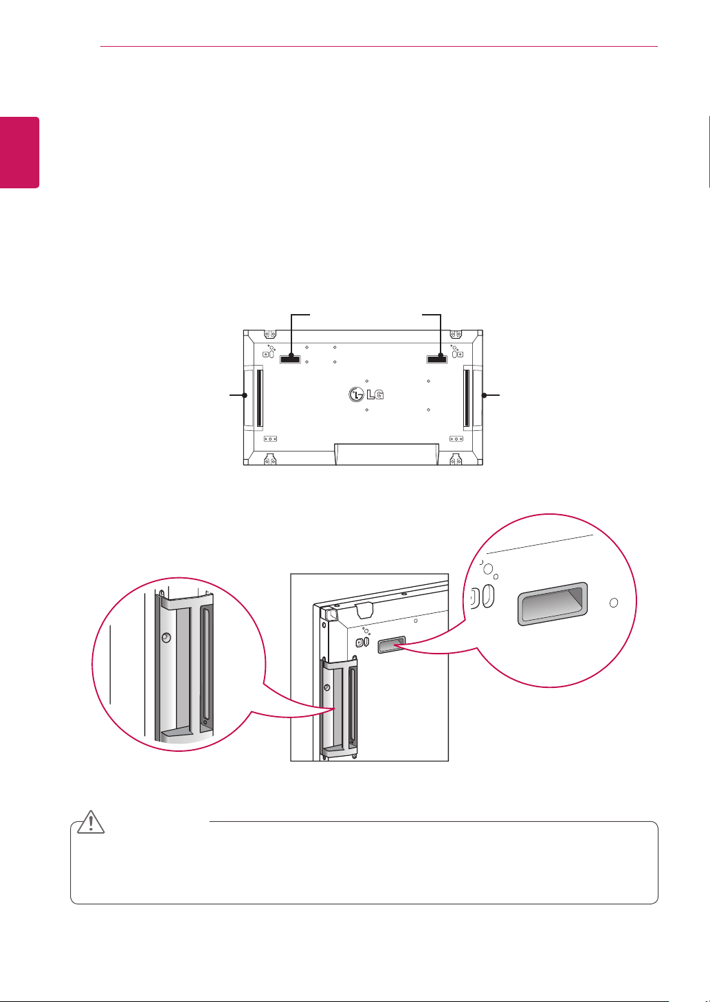
Remove L-brackets before Installation
Remove the L-brackets from each corner of the monitor before installing it.
ENGLISH
ENG
NOTE
Keep the removed L-brackets and use them when moving the monitor later.
ASSEMBLING AND PREPARING
8
ENGLISH
Moving Handles
ENG
Moving the device in a vertical position
Hold the vertical handles on the left and right
sides or the left and right handles on the back of
the display.
Vertical handle
on the side
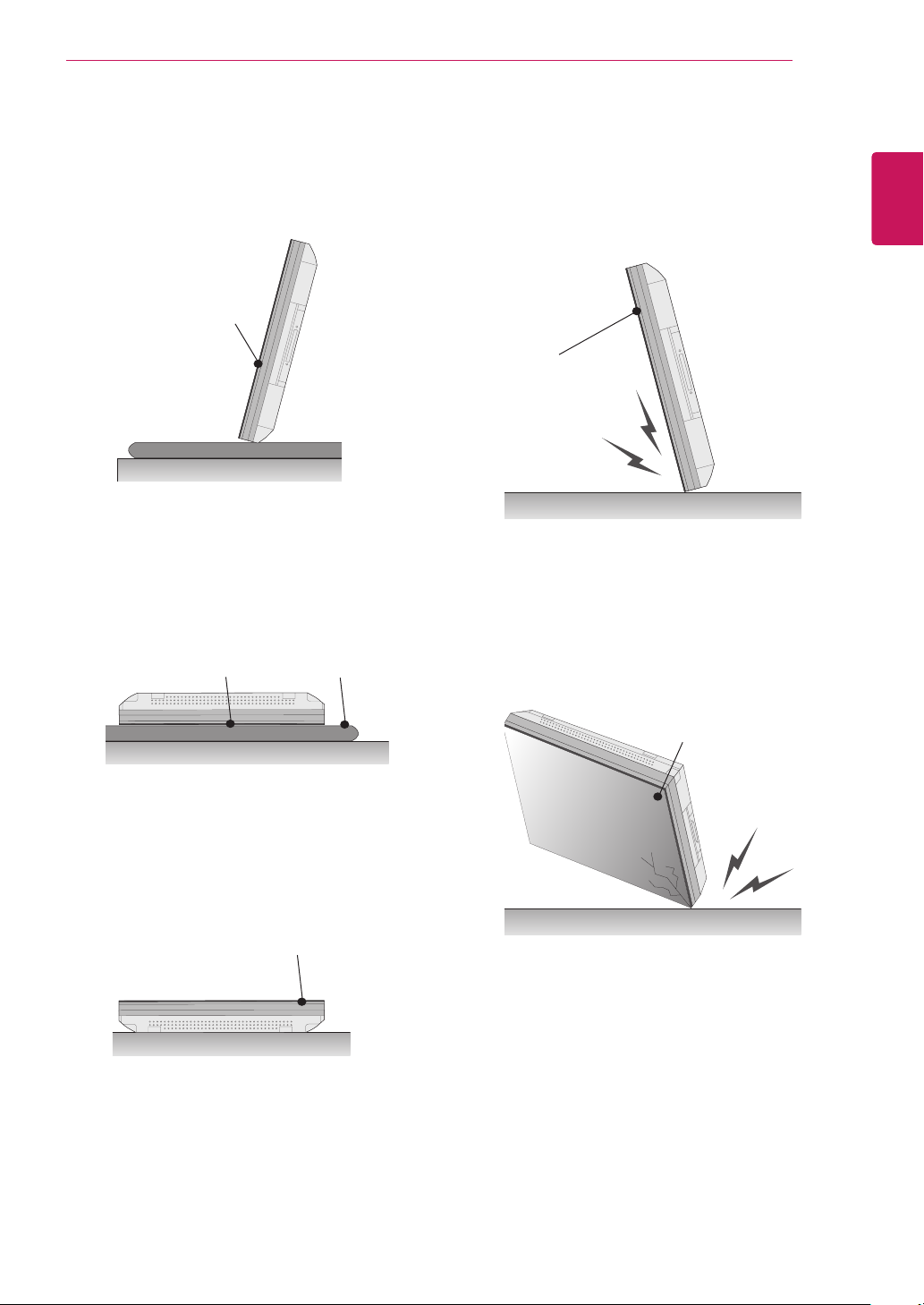
Moving the device in a horizontal position
Have the screen facing down and hold the vertical
handles on the left and right sides.
Left and right handles
at the back
Vertical handle
on the side
CAUTION
Be careful not to directly touch the panel or expose it to shock when moving the monitor.
y
Hold the monitor with the handles as the corners of the front panel are sharp, which may cause an
y
injury.
ASSEMBLING AND PREPARING
9
STORAGE METHOD FOR PANEL PROTECTION
Correct Method Incorrect Method
Panel
Panel
If the product needs to be set upright, hold both
sides of the product, and tilt backward carefully
for. Do not let the panel not to touch the floor.
If the product is tilted onto the bezel, the bottom of
the panel may be damaged.
ENGLISH
ENG
Panel
When laying down the product, lay a cushion on a
flat floor. Put the product on it with the panel of
the product facing down.
Cushion
Panel
If there is not a cushion available, ensure the floor is
clean and then lay the product down carefully with the
panel facing either upward or downward.
be careful for objects not to fall on the panel.
At this time,
Panel
If the product is tilted onto the edge of the panel,
the panel may be damaged.
ASSEMBLING AND PREPARING
10
ENGLISH
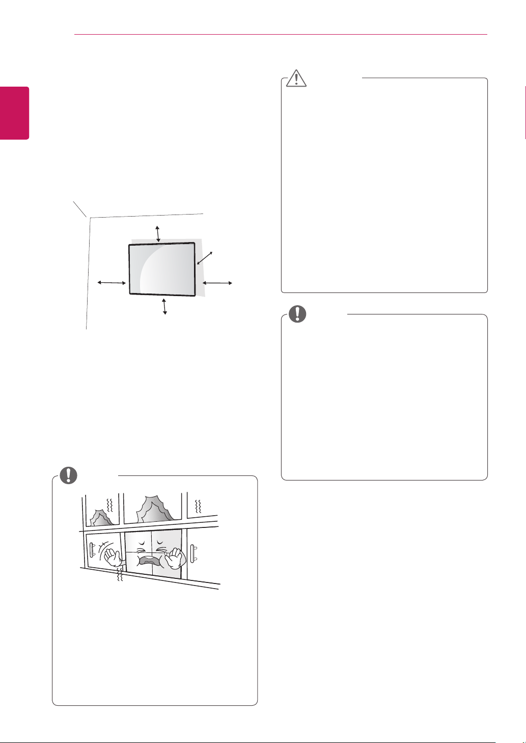
Installing on a wall
ENG
Install the monitor at least 10 cm away from the
wall and leave about 10 cm of space at each side
of the monitor to ensure sufficient ventilation. Detailed installation instructions can be obtained from
your local retail store. Please refer to the manual
to install and set up a tilting wall mounting bracket.
If you want to mount the monitor on the wall (optional), attach the wall mounting bracket to the rear
of the monitor.
Make sure that the wall mounting bracket is securely fixed to the monitor and to the wall.
Use the wall mount plate and screws that comply
with the VESA standard.
Use the wall mount plate and screws conforming
to the VESA standard.
NOTE
10 cm
10 cm
10 cm
20 cm
10 cm
CAUTION
Disconnect the power cord first, and then
y
move or install the Monitor set. Otherwise
electric shock may occur.
If you install the Monitor set on a ceiling or
y
slanted wall, it may fall and result in severe
injury. Use an authorized LG wall mount
and contact the local dealer or qualified
personnel.
Do not over tighten the screws as this may
y
cause damage to the Monitor set and void
your warranty.
Use the screws and wall mounts that
y
meet the VESA standard. Any damages
or injuries by misuse or using an improper
accessory are not covered by the warranty.
NOTE
Use the screws that are listed on the VESA
y
standard screw specifications.
The wall mount kit includes an installation
y
manual and necessary parts.
The wall mount bracket is optional. You can
y
obtain additional accessories from your local
dealer.
The length of screws may differ depending
y
on the wall mount. Be sure to use the proper
length.
For more information, refer to the
y
instructions supplied with the wall mount.
Do not install the product in a place with
y
no ventilation (e.g., on a bookshelf or in a
closet) or on a carpet or cushion. If there is
no other option but to mount the product on
the wall, make sure that sufficient ventilation
is provided before installation.
- Failure to do so may result in a fire due to
the increase in the internal temperature.
ASSEMBLING AND PREPARING
11
EXTERNAL EQUIPMENT SETUP
IR RECEIVER
This allows a remote control sensor to be placed
in a custom location. Then that display can control
other displays via an RS-232 cable. Refer to page
19 for more information.
AUDIO
(RGB/DVI)
REMOTE
CONTROL IN
ENGLISH
ENG
ASSEMBLING AND PREPARING
12
ENGLISH
Tiling Displays
ENG
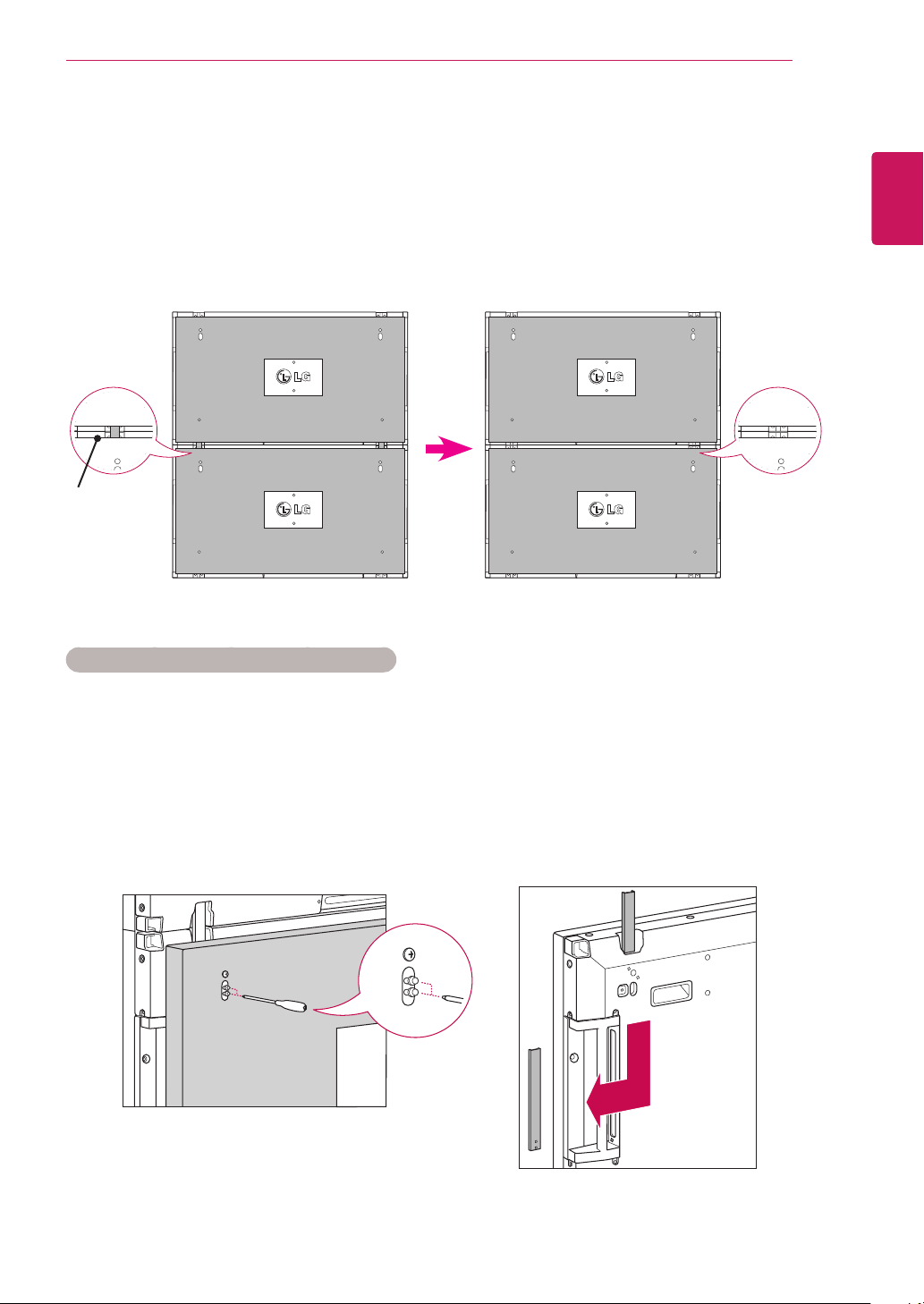
How to Join Sets - Installing Set 1
* The numbers assigned in this example (#1, #2, #3, #4) are used to demonstrate the installation procedure
*Example of 2 x 2 tiling
to ensure it is easy to follow. These numbers have nothing to do with the Set ID that is used to operate the
remote control. Set the guide bracket into the bracket groove using screws and mount the set to the wall
mount plate or the wall.
Guide bracket
Screws for attaching
the VESA wall mount
Guide bracket
Wall mount plate
<Rear view of the set with the wall mount plate>
* The wall mount plate is shaded in gray in the illustration to help you see it.
Screws for attaching
the guide bracket
ASSEMBLING AND PREPARING
How to Join Sets - Installing Set 2
Join Set 2 to Set 1 using the guide brackets on the top side of Set 1 and mount the two sets to the wall
mount plate or the wall.
Remove the guide brackets after mounting the sets.
<The sets joined with the guide brackets> <The sets after removing the guide brackets>
13
ENGLISH
ENG
Guide bracket
<Rear view of the set with the wall mount plate>
Remove the
guide brackets
How to remove the guide brackets
* Unscrew the guide bracket screws from the rear of the set and remove the guide brackets.
* Once the screws are removed, the guide brackets will drop. You need to remove them through the gap
on the sides of the set.
* This can be done only when there is enough space between the set and the wall mount plate or the wall
to unscrew the screws. (Please check whether there is enough space to remove the screws before fixing
the guide brackets.)
<Removing the guide bracket through
the side gap>
14
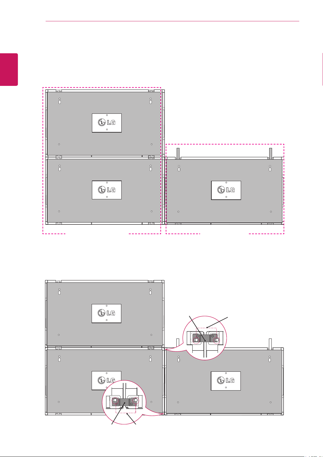
How to Join Sets - Installing Set 3
ENGLISH
ENG
Fix the guide brackets to Set 3 following the steps above, and loosely mount the set to the wall mount
plate or the wall.
ASSEMBLING AND PREPARING
#2
#1 #3
<Joined Sets 1 and 2> <Set 3 to be joined>
Minimize the space between the sides of the sets using the U-shaped fixture.
Fix the 2 sets using the provided screws. At this point, make sure to minimize the space between them.
Use a hex head wrench for fixing the screws.
U bracket
Screws for xing U bracket
U bracket
Screws for xing U bracket
ASSEMBLING AND PREPARING
15
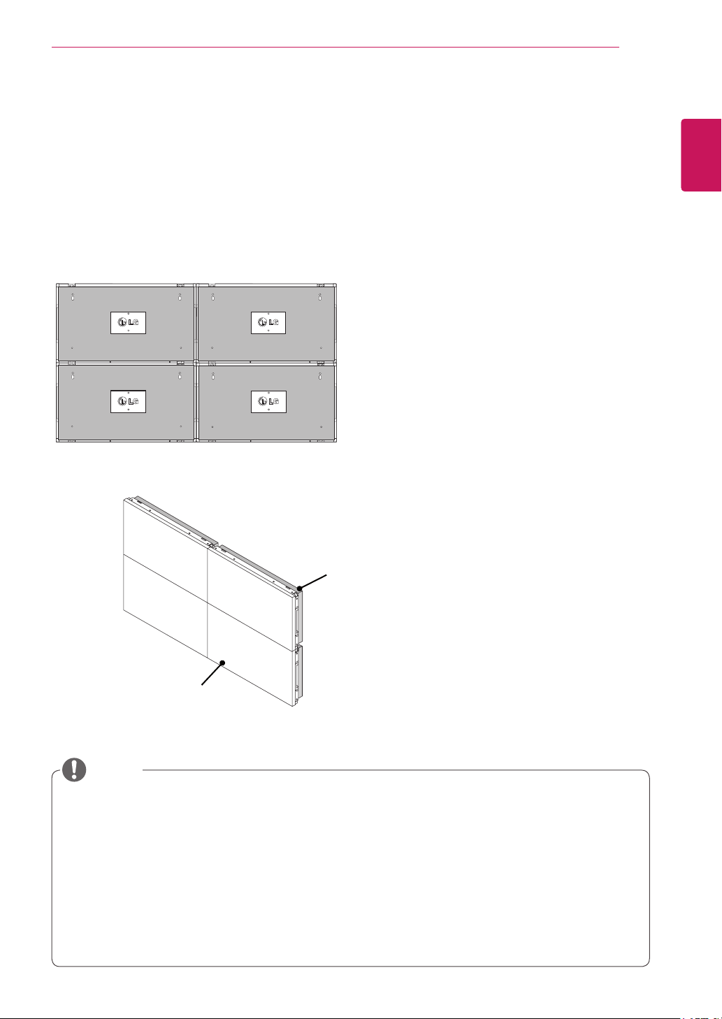
How to Join Sets - Installing Set 4
Loosely mount Set 4 to the wall mount plate or the wall and minimize the space between the sets using
the U-shaped fixtures.
When Set 4 is firmly mounted to the wall, remove the U-shaped fixtures. Remove the guide brackets. See
<How to Join Sets - Installing Set2,3>.
Now the 2 x 2 tiling is complete.
You can tile in various combinations, such as 3 x 3.
Set 4 joined to the rest of the sets
(2 x 2 tiling)
ENGLISH
ENG
Wall mount plate or wall
Display set
NOTE
The guide brackets for tiling should only be used to join sets and should be removed once they are joined.
y
The guide brackets should only be used as the assisting tool when tiling sets. The load applied to each set
y
should be supported by the wall mount plate or the wall using a VESA wall mount (800 x 400).
The guide bracket is used as a guide only, when joining each set. The load applied to each set should be
y
supported by the wall mount plate using a VESA wall mount. (Each set must be firmly mounted to the wall mount
plate or the wall.)
The guide brackets must be removed once the sets are joined. When joining the sets without removing the guide
y
brackets, extra caution is required to prevent damage due to the set weight.
You may mount the set without using the guide brackets or the U-shaped fixtures; this does not affect the
y
performance of the device.
ASSEMBLING AND PREPARING
16
ENGLISH
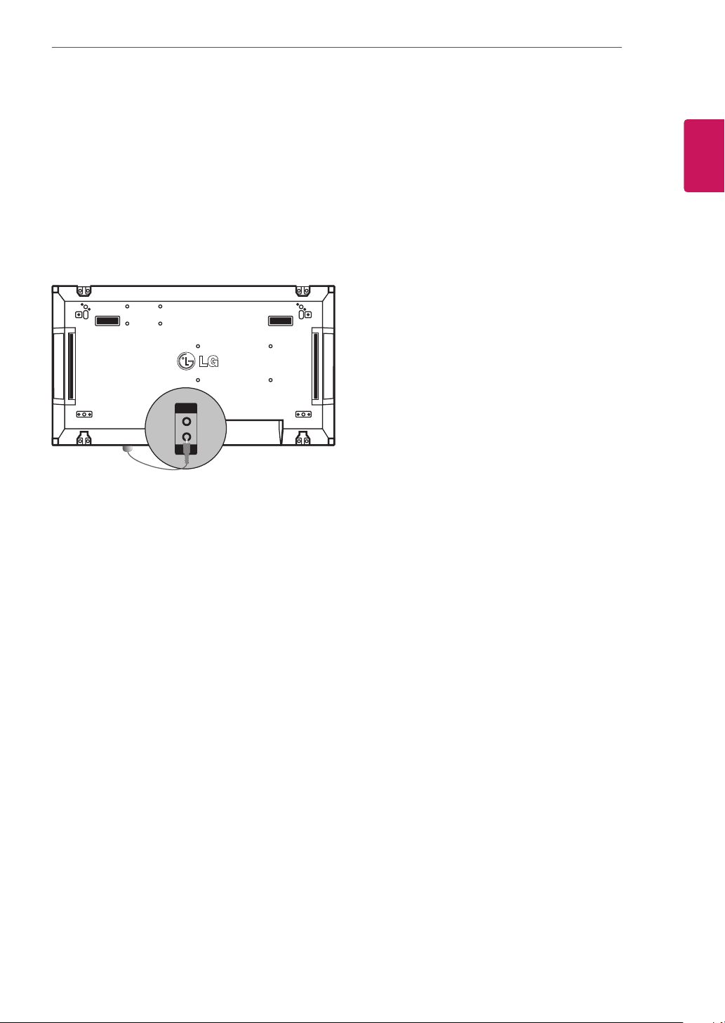
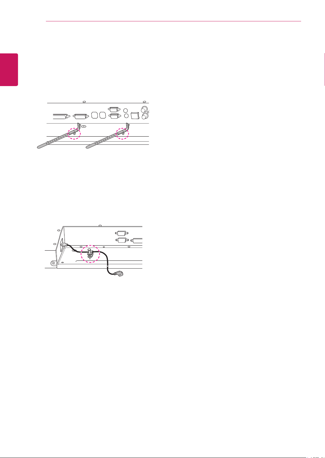
Inserting the Cable Holder
ENG
As illustrated, insert two cable holders into the
holes at the bottom rear of the set to organize the
cable bundles.
As illustrated, screw the power cable holder into
the hole on the bottom rear of the set to hold the
power cables together. (This is to put the power
cables inside the holder.)
REMOTE CONTROL
G
S
G
C
1
4
G
5
JKL6MNO
7
PQ
9
0
- * #
C
R
ON
F
MONITOR
MUTE
T
N
POWER
P
A
G
E
INPUT
ENERGY
SAVING
MARK
ARC
ON
OFF
. , !
ABCDEF
GHI
JKL
MNO
PQRS
TUV
1/a/A
- * #
WXYZ
CLEAR
S.MENU
MONITOR
PSM
AUTO
MUTE
BRIGHT
NESS
MENU
POWER
17
REMOTE CONTROL
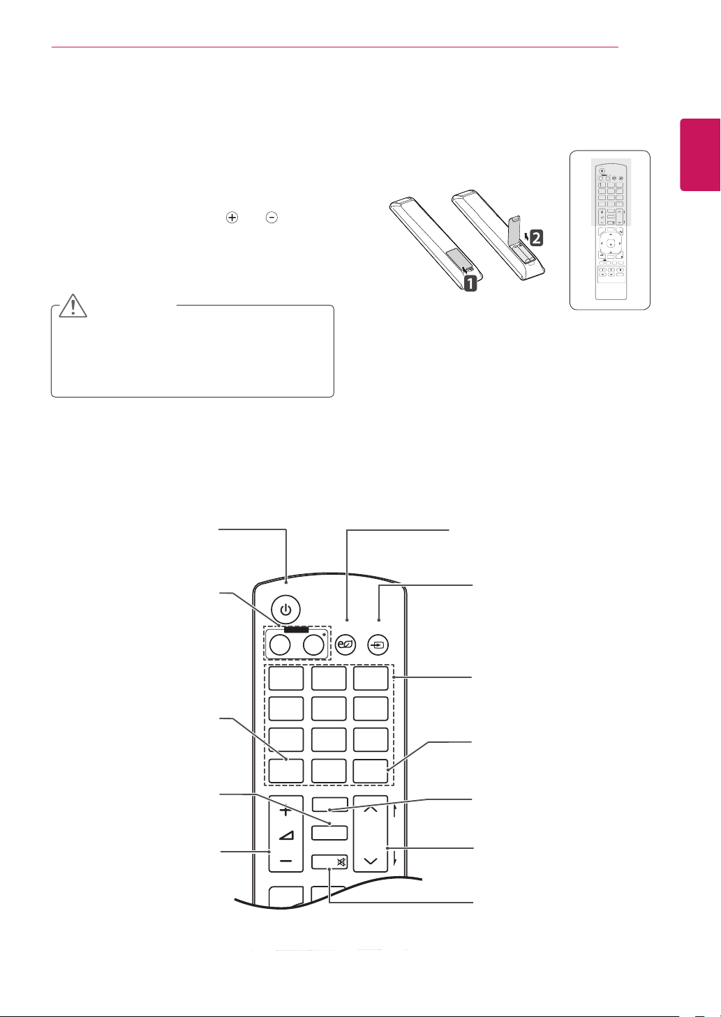
The descriptions in this manual are based on the buttons of the remote control. Please
read this manual carefully and use the Monitor set correctly.
To replace batteries, open the battery cover, replace
batteries (1.5 V AAA) matching and ends to the
label inside the compartment, and close the battery
cover. To remove the batteries, perform the installation
actions in reverse.
CAUTION
Do not mix old and new batteries, as this
y
may damage the remote control.
Make sure to point the remote control at the
y
remote control sensor on the Monitor.
Make sure to point the remote control to the remote control sensor on the Monitor set.
POWER
MONITOR
ON
1
. , !2ABC3DEF
. , !2ABC3DEF
4
GHI5JKL6MNO
HI
7
PQRS8TUV
RS8TUV
1/a/A
1/a/A
MENU
BACK
ID
ON
ENGLISH
ENG
INPUT
INPUT
ENERGY
ENERGY
OFF
OF
AVIN
SAVING
9
WXYZ
WXYZ
CLEAR
LEA
0
- * #
MARK
MARK
ARC
AR
P
A
BRIGHT
BRIGH
PSM
PSM
G
ESS
NESS
E
MUTE
AUTO
S.MENU
OK
EXIT
TILE
OFF
Power On / Off
Switches the set on from
standby or off to standby.
Monitor On / Off
Turn off the monitor and then
turn it back on.
applicable.
1/a/A
This button selection is not
PSM
Selects the Picture Status
Mode.
Volume Up/Down
Adjusts the volume.
Energy Saving
Adjust the Energy Saving
mode of the SET.
INPUT
If you press the button once, the
following Input Signal Window
will appear. Select the signal
type you want using the button.
Number and Alphabet
Type numbers.
The alphabet selection is not
applicable.
Clear
This button selection is not
applicable.
ARC
Selects the Aspect Ratio Mode.
BRIGHTNESS
Moves to the previous or next
screen.
MUTE
Switches the sound on or off.
18
OK
S
U
U
ON
E
P
A
G
E
INPUT
ENERGY
SAVING
MARK
ARC
ON
OFF
. , !
ABCDEF
GHI
JKL
MNO
PQRS
TUV
1/a/A
- * #
WXYZ
CLEAR
MONITOR
PSM
BRIGHT
NESS
POWER
ENGLISH
ENG
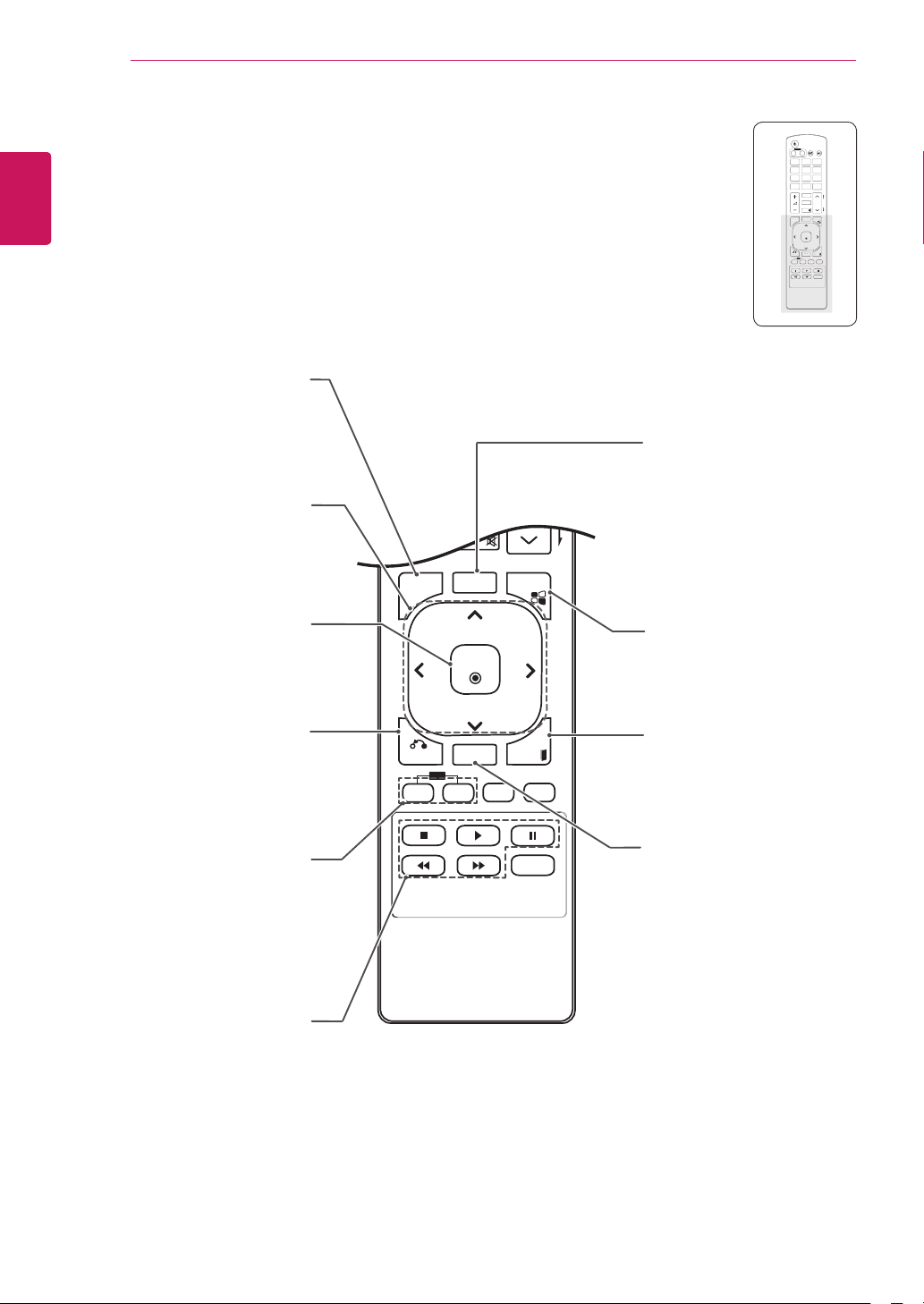
REMOTE CONTROL
MENU(See p.43)
Selects a menu.
Clears all on-screen displays
and returns to Set viewing
Allows you to navigate the
on-screen menus and adjust
the system settings to your
from any menu.
Up/Down/Left/Right
preference.
MENU
MUTE
AUTO
S.MENU
POWER
INPUT
ENERGY
MONITOR
OFF
ON
SAVING
1
. , !2ABC3DEF
4
GHI5JKL6MNO
7
9
WXYZ
PQRS8TUV
1/a/A
CLEAR
0
- * #
MARK
ARC
P
A
BRIGHT
PSM
G
NESS
E
MUTE
AUTO
AUTO
S.MENU
.MEN
MENU
MEN
OK
XIT
EXIT
BACK
BACK
TILE
IL
ID
ID
OFF
OFF
ON
AUTO
Automatically adjusts picture
position and minimizes image
instability.(RGB input only)
OK
Accepts your selection or
back one step in an interactive
displays the current mode.
Allows the user to move
application.
BACK
ID ON/OFF
Allows you to set the Picture
ID or turn it off. Use this
button to control the individual
monitors connected in RS-
232C mode. (It works properly
only when Set IDs are
assigned.)
USB Menu control
Controls media playback.
BACK
ON
S.MENU
(SuperSign Menu Key)
OK
This button selection is not
applicable.
EXIT
EXIT
TILE
ID
OFF
Clears all on-screen displays
and returns to Monitor set
viewing.
TILE
Selects the TILE Mode.
REMOTE CONTROL
P
A
G
E
INPUT
ENERGY
SAVING
MARK
ARC
ON
OFF
. , !
ABCDEF
GHI
JKLMNO
PQRSTUV
1/a/A
- * #
WXYZ
CLEAR
OK
S.MENU
MONITOR
PSM
AUTO
MUTE
BRIGHT
NESS
MENU
ID
BACK
TILE
ON
OFF
EXIT
POWER
P
A
G
E
INPUT
ENERGY
SAVING
MARK
ARC
ON
OFF
. , !
ABCDEF
GHIJKLMNO
PQRSTUV
1/a/A
- * #
WXYZ
CLEAR
OK
S.MENU
MONITOR
PSM
AUTO
MUTE
BRIGHT
NESS
MENU
ID
BACK
TILE
ON
OFF
EXIT
POWER
19
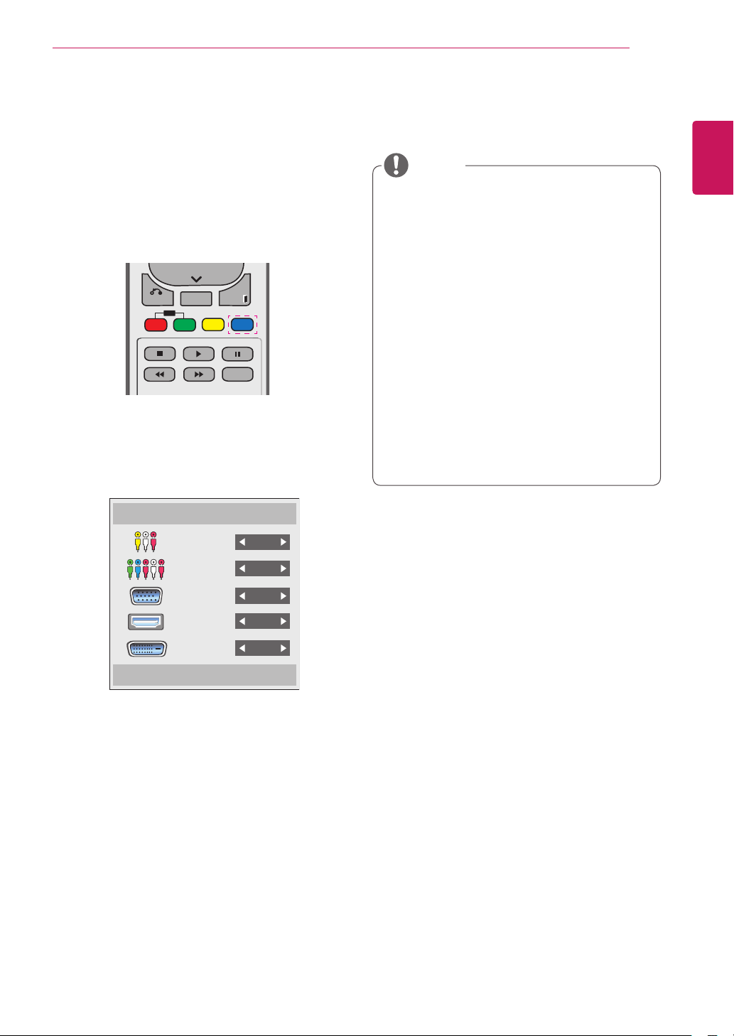
Displaying the device name connected to an input port
Display which devices are connected to which
external input ports.
1 Access the Input list screen and press the blue
(input label) button on the remote control.
2 You can assign an input label for every input
except USB.
Input Label
NOTE
External inputs supported: AV, Component,
y
RGB, HDMI, DVI-D. (AV only support 47WV30BR and 47WV30MS)
Labels available : VCR, DVD, Set top box,
y
Satellite, Game, PC, Blue-ray, HD-DVD
The input labels are displayed on the Input
y
Label screen or at the top left of the screen
when you change the external input setting.
For DTV/PC-compatible signals, such as
y
1080p 60 Hz, the screen settings may
change according to the input label. The Just
Scan option is available if a PC is connected
as an external device. (1080p only support
47WV30BR and 47WV30MS)
47WV30-BAAL/47WV30-BAAM/47WV30BS
y
does not support AV input.
ENGLISH
ENG
AV
Component
RGB
HDMI
DVI-D
Close
REMOTE CONTROL
AUDIO
(RGB/DVI)
REMOTE
CONTROL IN
RS-232C OUT
RS-232C IN
RS-232C OUT
RS-232C IN
RS-232C OUT
RS-232C IN
P
A
G
E
INPUT
ENERGY
SAVING
MARK
ARC
ON
OFF
. , !
ABCDEF
GHI
JKLMNO
PQRSTUV
1/a/A
- * #
WXYZ
CLEAR
OK
S.MENU
MONITOR
PSM
AUTO
MUTE
BRIGHT
NESS
MENU
ID
BACK
TILE
ON
OFF
EXIT
POWER
P
A
G
E
INPUT
ENERGY
SAVING
MARK
ARC
ON
OFF
. , !
ABCDEF
GHIJKLMNO
PQRSTUV
1/a/A
- * #
WXYZ
CLEAR
OK
S.MENU
MONITOR
PSM
AUTO
MUTE
BRIGHT
NESS
MENU
ID
BACK
TILE
ON
OFF
EXIT
POWER
20
ENGLISH
Picture ID
ENG
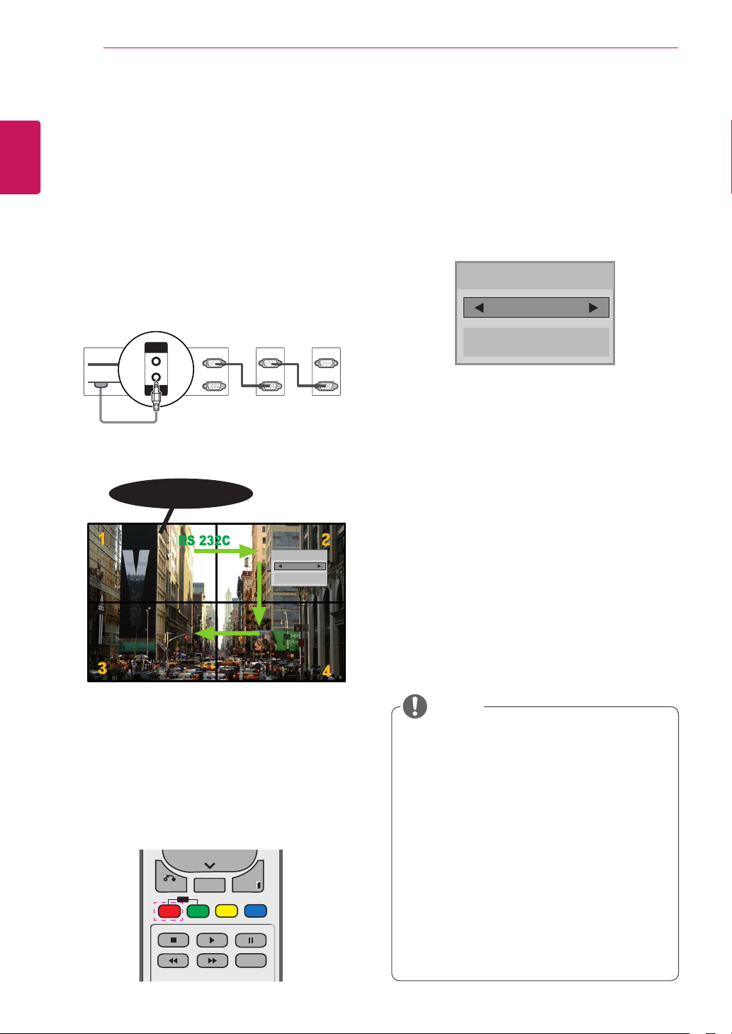
Picture ID is used to change the settings of a
specific set (display) using a single IR receiver for
multi-vision. The set receiving the IR signal communicates with another set via the RS232 connector. Each set is identified by a Set ID. If you assign the Picture ID using the remote control, only
displays with the same Picture ID and Set ID can
be controlled remotely.
AUDIO
(RGB/DVI)
REMOTE
CONTROL IN
IR Receiver
RS-232C OUT
RS-232C IN
RS-232C OUT
RS-232C IN
Picture ID
Off
Close
RS-232C OUT
RS-232C IN
2 If you press the left/right buttons or press the
ON button repeatedly, the Picture ID cycles
through OFF and 1 to 4.Assign the ID you
want.
Picture ID
Off
Close
If you assign the Set ID to each set with
y
multi-vision, and then assign the Picture ID
using the red button on the remote control,
the key command is displayed for the set
with the same Set ID and Picture ID. A set
with different Set IDs and Picture IDs cannot
be controlled by IR signals.
The maximum value of the Picture ID can be
y
set in the Total Set ID menu.
Please refer to the Installation Manual for
y
more information on the assignment of a
Total Set ID.
2X2 Multi-Vision (Total Set ID: 4)
Set IDs are assigned as shown in the picture.
1 Press the ID On (Red) button on the remote con-
trol.
NOTE
For example, if the Picture ID is assigned
y
to 2, the upper right display (Set ID: 2) can
be controlled by IR signals.
For each set, you can change the settings
y
for the PICTURE, AUDIO, TIME, OPTION,
NETWORK and MY MEDIA menus or the
hot keys on the remote control.
If you press the ID OFF (Green) button,
y
the Picture IDs for all sets are turned off. If
you then press any button on the remote
control, all sets will start working again.
The Picture ID function may not work dur-
y
ing MY MEDIA operating.
USING THE MONITOR SET
RGB OUT
RGB IN
AUDIO
(RGB/DVI)
REMOTE
CONTROL IN
DVI IN
/DVI
21
USING THE MONITOR SET
Connecting to a PC
NOTE
It is recommended to you use an HDMI
y
connection for the best image quality.
CAUTION
Connect the signal
y
input cable and tighten
it by turning the screws
clockwise.
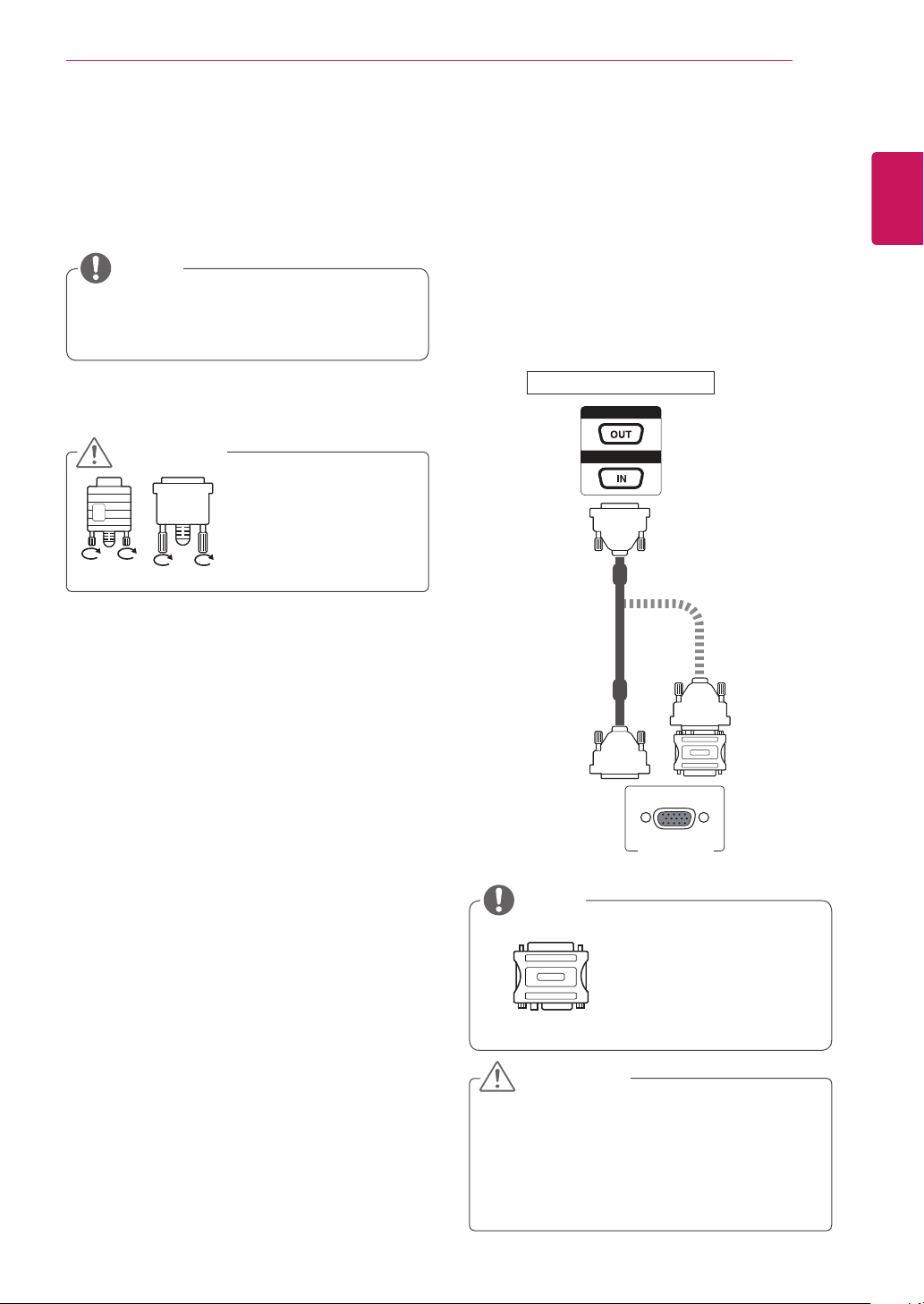
RGB connection
Transmits an analog video signal from your PC to
the Monitor set. Connect the PC and the Monitor
set with the D-sub 15 pin cable as shown the
following illustrations. Select RGB input source on
the monitor.
ENGLISH
ENG
Back of the Monitor Set
PC
NOTE
Apple computers may
y
require an adapter
to connect to this
monitor. Call or visit
their web site for more
information.
CAUTION
Do not press the screen with your finger for
y
it may damage the screen.
Avoid displaying a fixed image on the
y
screen for a long period of time to prevent
image burn. Use a screensaver if possible.
USING THE MONITOR SET
AUDIO
(RGB/DVI)
REMOTE
CONTROL IN
/DVI
AUDIO
(RGB/DVI)
REMOTE
CONTROL IN
DVI IN
/DVI
22
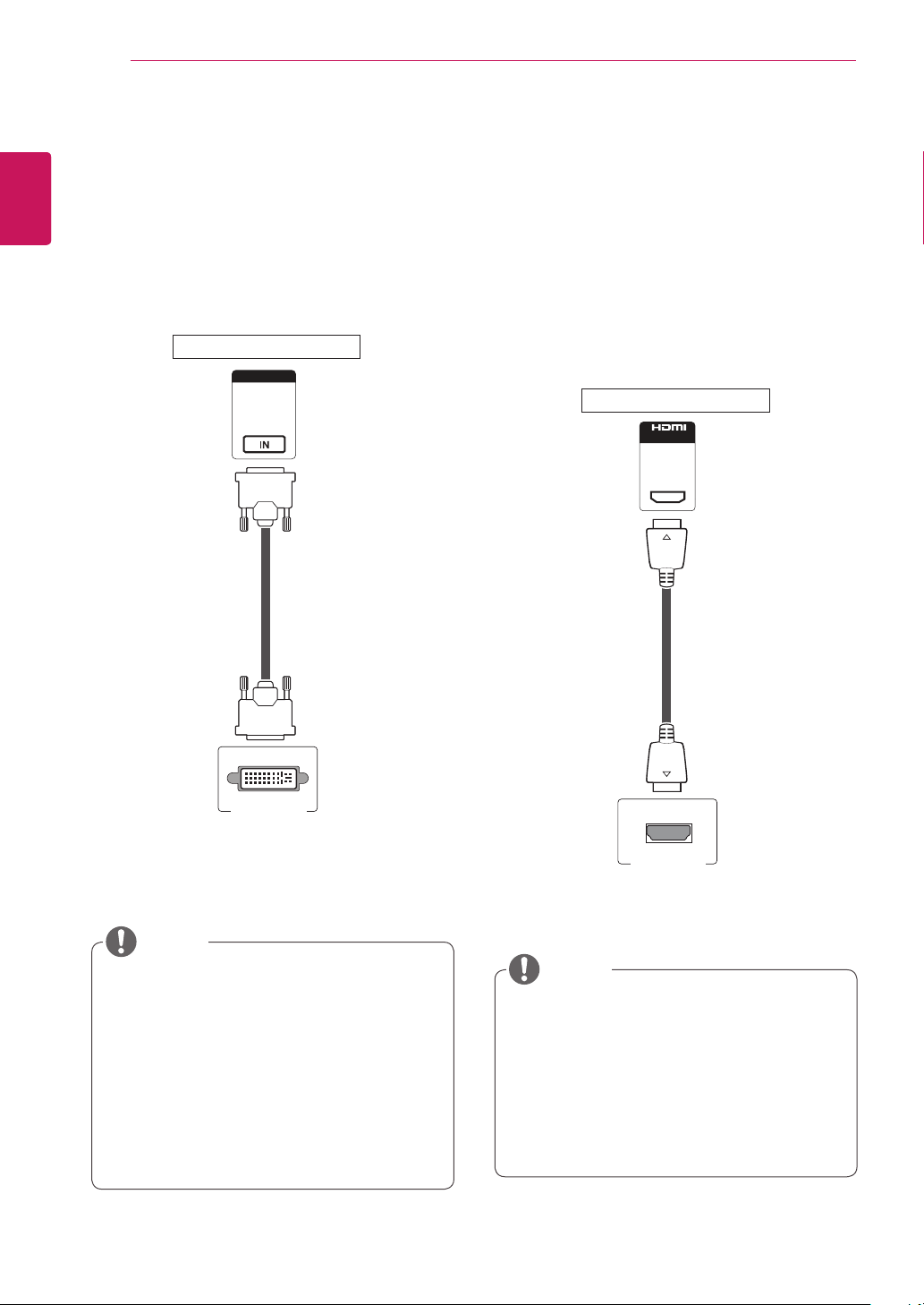
DVI connection
ENGLISH
ENG
Transmits the digital video signal from your PC to
the Monitor set. Connect the PC and the Monitor
set with the DVI cable as shown the following
illustrations.
Select DVI-D input source on the monitor.
HDMI connection
Transmits the digital video and audio signals from
your PC to the Monitor set. Connect the PC and
the Monitor set with the HDMI cable as shown
in the following illustrations. Select HDMI input
source on the monitor.
Back of the Monitor Set
Back of the Monitor Set
PC
NOTE
If you do not use an optional external
y
speaker, connect the PC to the Monitor set
with audio cable.
Use a shielded signal interface cable, such
y
as D-sub 15 pin signal cable and DVI to
HDMI cable, with a ferrite core to maintain
standard compliance for the product.
If you want to use HDMI-PC mode, you must
y
set the input label to PC mode.
(not included)
PC
NOTE
Use a High Speed HDMI™ Cable.
y
Please check the PC environment if you
y
cannot hear the sound in HDMI mode.
If you want to use HDMI-PC mode, you must
y
set the input label to PC mode.
It may not be compatible if you use HDMI-PC
y
mode.
USING THE MONITOR SET
AUDIO
(RGB/DVI)
REMOTE
CONTROL IN
AUDIO
(RGB/DVI)
REMOTE
CONTROL IN
DVI IN
/DVI
AUDIO
(RGB/DVI)
REMOTE
CONTROL IN
23
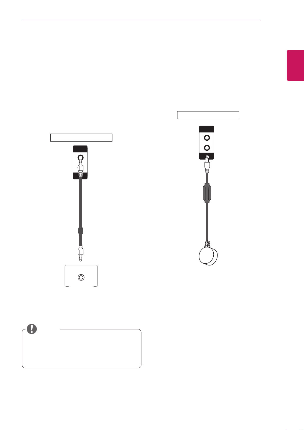
Audio connection
Transmits the audio signals from your PC to the
Monitor set. Connect the PC and the Monitor set
with the Audio cable as shown in the following
illustrations. You should set PC as an input label
to connect the PC to the Monitor set with an Audio
connection.
Back of the Monitor Set
(not included)
IR Receiver connection
Allows the use of a wired remote or IR receiver
extension.
Back of the Monitor Set
ENGLISH
ENG
PC
NOTE
To ensure the best sound quality and
y
minimize noise, keep the cable as short as
possible.
USING THE MONITOR SET
24
ENGLISH
Adjusting the screen
ENG
Selecting an image mode
Display images using optimized settings by
selecting one of the preset image modes.
1
2
3
4
5
Press MENU to access the main menus.
Press the Navigation buttons to scroll to
PICTURE and press OK.
Press the Navigation buttons to scroll to
Picture Mode and press OK.
Press the Navigation buttons to scroll to an
image mode you want and press OK.
Mode Description
Vivid Adjusts the video image for the retail
environment by enhancing the Contrast,
Brightness, Color, and Sharpness.
Standard Adjusts the image for the normal
environment.
Cinema Optimizes the video image for the
cinematic look and enjoy movies as if you
are in a movie theater.
Sports Optimizes the video image for high and
dynamic actions by emphasizing primary
Colors such as white, grass, or sky blue.
Game Optimizes the video image for a fast
gaming screen such as PCs or games.
When you are finished, press EXIT.
When you return to the previous menu, press
BACK.
Customizing image options
Customize basic and advanced options of each
image mode for the best screen performance.
Press MENU to access the main menus.
1
Press the Navigation buttons to scroll to
2
PICTURE and press OK.
Press the Navigation buttons to scroll to
3
Picture Mode and press OK.
Press the Navigation buttons to scroll to an
4
image mode you want and press OK.
Select and adjust following options, and then
5
press OK.
Option Description
Backlight Adjusts the brightness of the screen
by controlling the LCD backlight. If
you decrease the brightness level,
the screen becomes darker and the
power consumption will be reduced
without any video signal loss.
Contrast Increases or decreases the gradient
of the video signal. You may use
Contrast when the bright part of the
image is saturated.
Brightness Adjusts the base level of the signal in
the image. You may use Brightness
when the dark part of the image is
saturated.
Sharpness Adjusts the level of crispness in the
edges between the light and dark
areas of the picture. The lower the
level, the softer the image.
Color Adjusts the balance between Red
and Green levels.
Tint Adjusts intensity of all Colors.
Color
Temperature
Set to warm to enhance hotter Colors
such as red, or set to cool to make
picture bluish.
 Loading...