

Easy Setup Guide Specification
Easy Setup Guide Specification
담 당 관리자
H.J LEE
1. Model Description
MODEL
SUFFIX
2.
1. Trim Size (Format) : 172 mm x 243 mm
2. Printing Colors
Cover : 1 COLOR (BLACK)
Inside : 1 COLOR (BLACK)
3. Stock (Paper)
Cover : Coated paper, Snow White 150 g/㎡
Inside : Uncoated paper, 백상지 60 g/㎡
4. Printing Method : Off-set
5. Bindery : Perfect bind
6. Language : English/Czech/Spanish/French/German/Greek/Italian/Polish/Slovak/Portuguese (10)
7. Number of pages : 200 pages (Including blank 10 pages)
N
O
T
E
S
47WV30-BAAM LG
World Wide
Printing Specification
* This part contain Eco-hazardous substances (Pb, Cd, Hg, Cr6+, PBB, PBDE, etc.) within LG
standard level, Details should be followed Eco-SCM management standard[LG(56)-A-2524].
Especially, Part should be followed and controlled the following specification.
(1) Eco-hazardous substances test report should be submitted
when Part certification test and First Mass Production.
(2) Especially, Don’t use or contain lead(Pb) and cadmium(Cd) in ink.
BRAND
Product Name
Signage
11.07.22
Part No.
SG KIM
11.07.22
MFL67420101
1107-REV00)
(
JO KIM
11.07.22
Special Instructions3.
(1) Origin Notification
* LGEIN : Printed in Indonesia * LGEWA : Printed in U.K * LGEMA : Printed in Poland
* LGESP : Printed in Brazil * LGEMX : Printed in Mexico
* LGEND : Printed in China * LGEIL : Printed in India
4.
Changes
8
7
6
5
4
3
2
1
REV.
MM/DD/YY
NO.
SIGNATURE
CHANGE NO.
CHANGE CONTENTS
Pagination sheet
Pagination sheet
Front cover
Total pages : 200 pages
English
ČESKY
ESPAÑOL
FRANÇAIS
DEUTSCH
2
2
2
2
2
3
3
3
3
3
…
…
…
…
…
17
17
17
17
17
18
18
18
18
18
Blank
Blank
Blank
Blank
Blank
ΕΛΛΗΝΙΚΑ
ITALIANO
POLSKI
2
2
2
3
3
3
…
…
…
17
17
17
18
18
18
Blank
Blank
Blank
Pagination sheet
Pagination sheet
Total pages :200 pages
SLOVENČINA
PORTUGUÊS
2
2
3
3
…
…
17
17
18
18
Blank
Blank
Back cover

ENGLISH
ENG
Easy Setup Guide
SIGNAGE DISPLAY
Please read this manual carefully before operating the your set and
retain it for future reference.
SIGNAGE DISPLAY MODELS
47WV30
P/NO : MFL67420101 (1107-REV00)
Printed in Korea
www.lg.com
ASSEMBLING AND PREPARING
2
ENGLISH
ENG
ASSEMBLING AND PREPARING
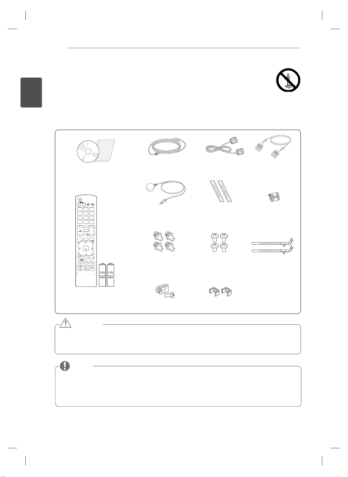
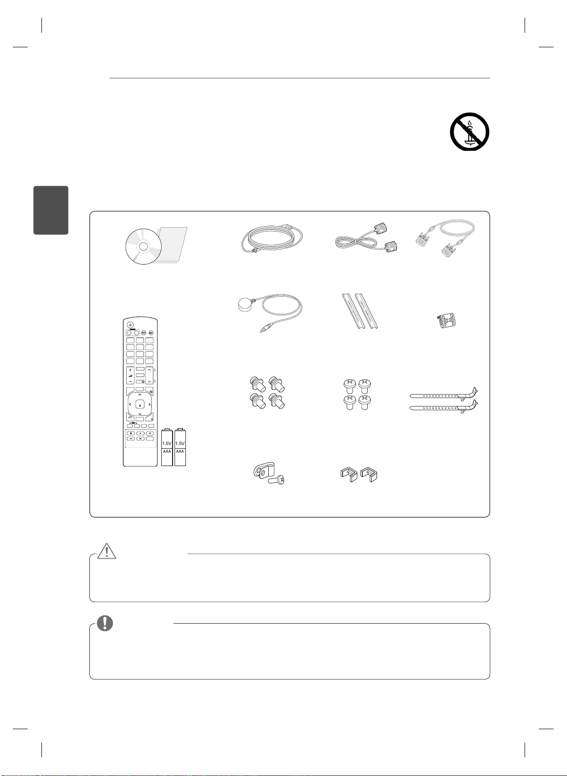
Unpacking
Check your product box for the following items. If there are any missing accessories, contact the local
dealer where you purchased your product. The illustrations in this manual may differ from the actual product
and accessories.
RGB Cable
M6
Screw (4ea)
Ring Core
Cable holder
(2ea)
CD (Owner's Manual) /
Card
POWER
INPUT
ENERGY
MONITOR
OFF
ON
SAVING
. , !ABCDEF
GHIJKLMNO
PQRSTUV
WXYZ
1/a/A
CLEAR
- * #
MARK
ARC
P
A
BRIGHT
PSM
G
NESS
E
MUTE
AUTO
S.MENU
MENU
OK
EXIT
BACK
TILE
ID
OFF
ON
Power Cord DVI Cable
IR Receiver Guide bracket
M4 x 10L
Screw (4ea)
Remote control and Batteries
Power cable holder U-shaped fixture
CAUTION
Do not use any pirated items to ensure the safety and product life span.
Any damages or injuries by using pirated items are not covered by the warranty.
NOTE
The accessories supplied with your product may vary depending on the model.
Product specifications or contents in this manual may be changed without prior notice due to upgrade
of product functions.

ASSEMBLING AND PREPARING
Dimensions (Width x Height x Depth) / Weight
H
3
ENGLISH
ENG
W
1047 mm x 592 mm x 91.1 mm / 29 kg
D
To view the User’s guide
“Insert CD ROM” in Computer
CD-ROM will open automatically .(for Window only)
My computer ➙ Digital_LG(CD-ROM) ➙ Index.htm Open
My computer ➙ Digital_LG(CD-ROM) ➙ Manual folder ➙ User's Guide Open
ASSEMBLING AND PREPARING
4
ENGLISH
ENG
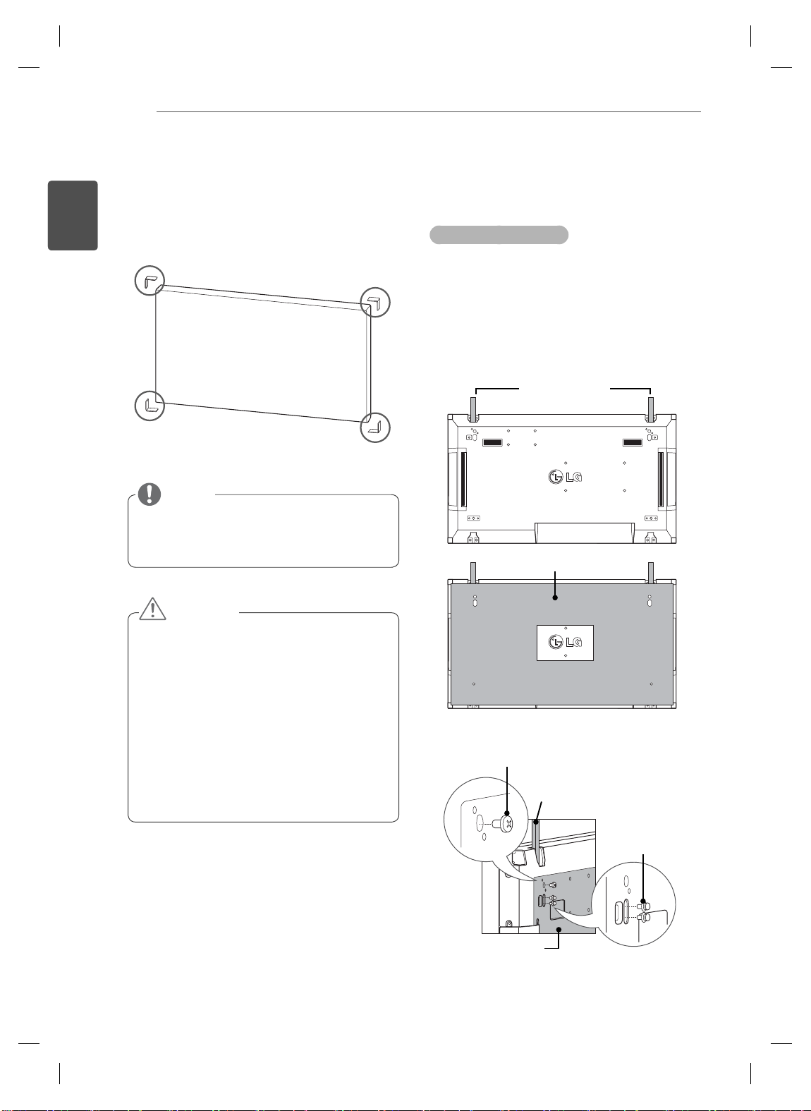
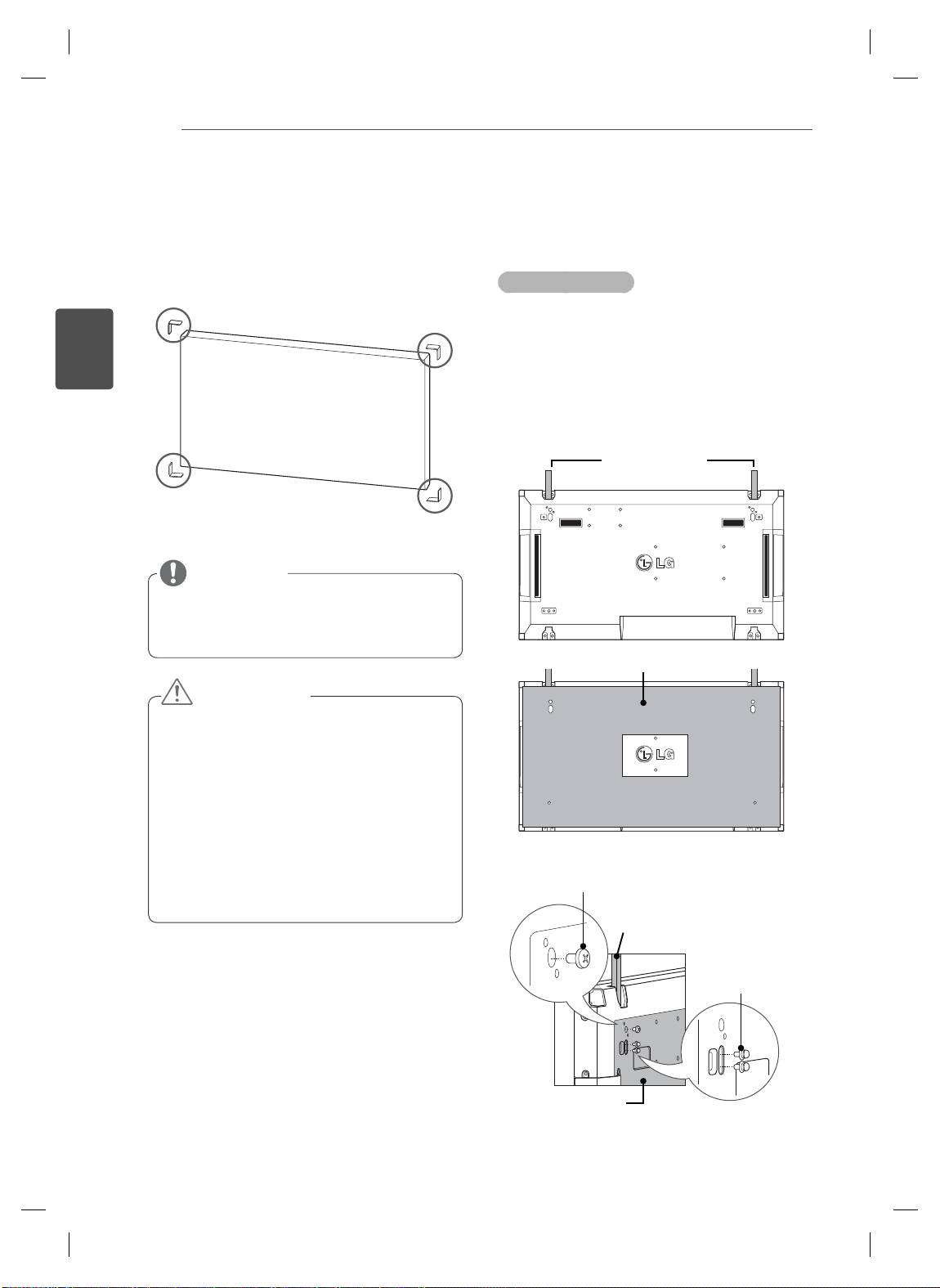
Remove L-brackets before
Installation
Remove the L-brackets from each corner of the
monitor before installing it.
NOTE
Keep the removed L-brackets and use them
when moving the monitor later.
Tiling Displays
How to Join Sets - Installing Set 1
*Example of 2 x 2 tiling
The numbers assigned in this example (#1,
#2, #3, #4) are used to demonstrate the
installation procedure to ensure it is easy to
These numbers have nothing to do
follow.
with the Set ID that is used to operate the
remote control.
Set the guide bracket into the bracket groove
using screws and mount the set to the wall
mount plate or the wall.
Guide bracket
Wall mount plate
CAUTION
When you connect Monitor sets for
multivision, you may find that the screen
color is not the same across all the Monitor
sets. If you want to adjust the screen color
manually, please refer to the Installation
Manual.
When you install multiple Monitor sets onto
a wall, attach the IR Receiver to all the
sets, or use an RS-232C cable to connect
them and then attach the IR Receiver to the
first set.
<Rear view of the set with the wall mount plate>
Screws for fi xing the
VESA wall mount
Guide bracket
Screws for fixing the
guide bracket
Wall mount plate
The wall mount plate is shaded in gray in the
illustration to help you see it.
ASSEMBLING AND PREPARING
5
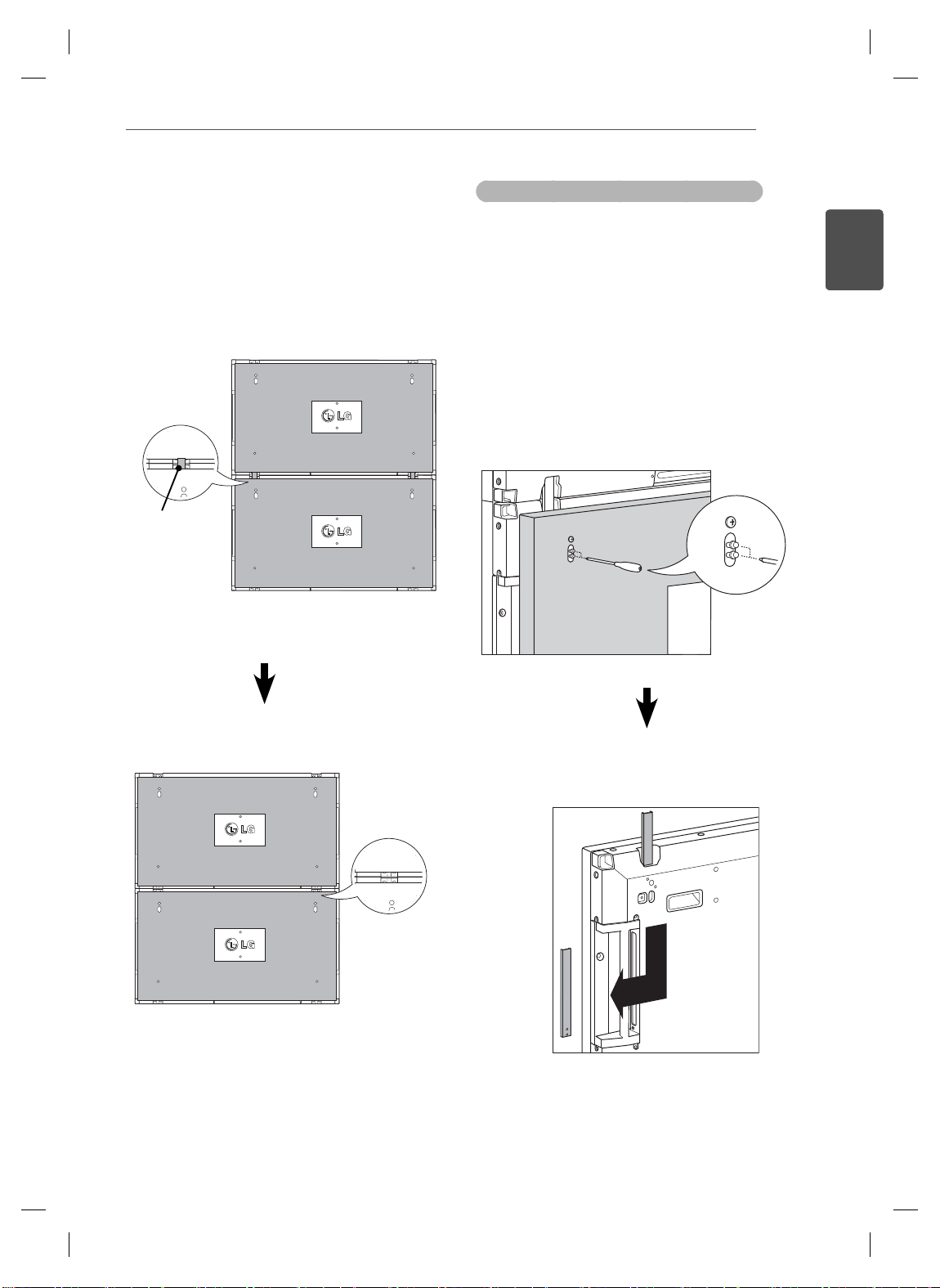
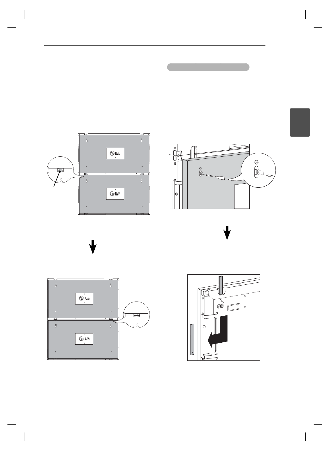
How to Join Sets - Installing Set 2
Join Set 2 to Set 1 using the guide brackets
on the top side of Set 1 and mount the two
sets to the wall mount plate or the wall.
Remove the guide brackets after mounting
the sets.
<The sets joined with the guide
Guide bracket
<Rear view of the set with the wall
brackets>
mount plate>
How to remove the guide brackets
Unscrew the guide bracket screws from
the rear of the set and remove the guide
brackets.
Once the screws are removed, the guide
brackets will drop. You need to remove them
through the gap on the sides of the set.
This can be done only when there is enough
space between the set and the wall mount
plate or the wall to unscrew the screws.
(Please check whether there is enough
space to remove the screws before fixing the
guide brackets.)
ENGLISH
ENG
<The sets after removing the guide
brackets>
<Removing the guide bracket through
the side gap>
Remove the
guide brackets
ENGLISH
ENG
ASSEMBLING AND PREPARING
6
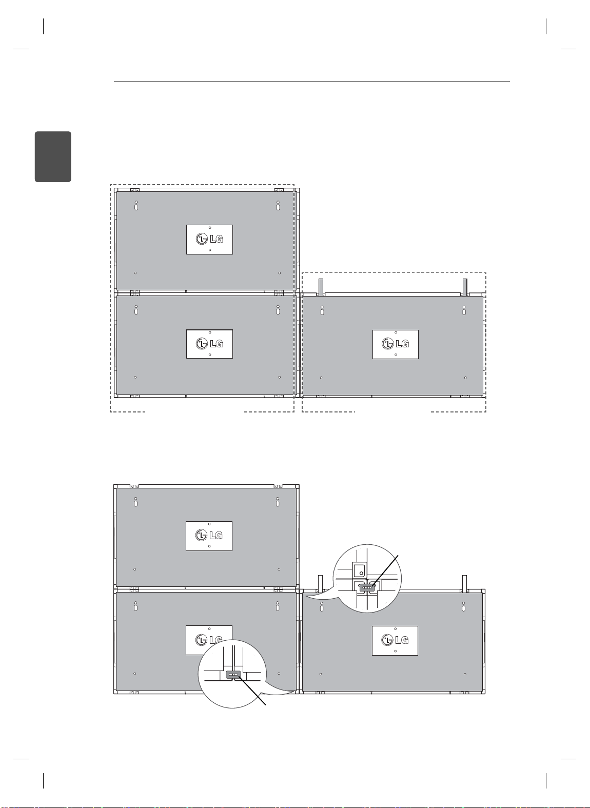
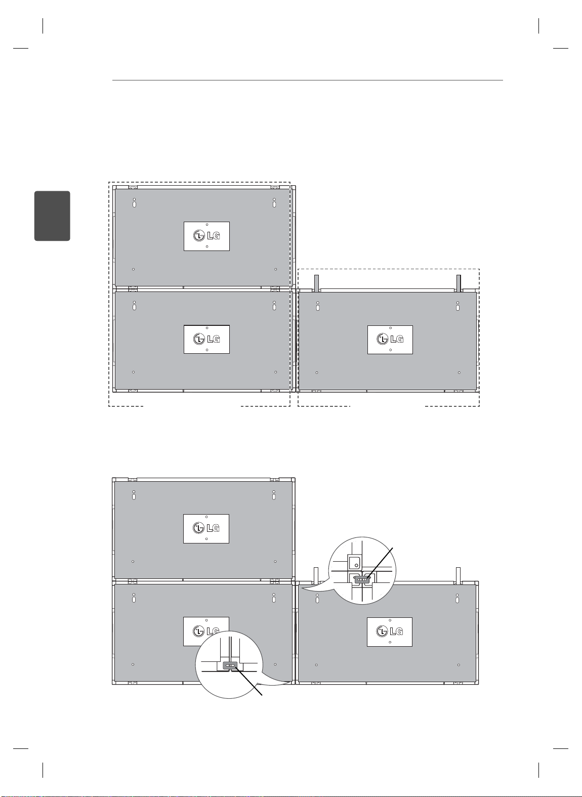
How to Join Sets - Installing Set 3
Fix the guide brackets to Set 3 following the steps above, and loosely mount the set to the wall mount
plate or the wall.
#2
#1 #3
<Joined Sets 1 and 2> <Set 3 to be joined>
Minimize the space between the sides of the sets using the U-shaped fixture.
When the sets are joined with the minimum amount of space between them, fi rmly mount them to the wall
mount plate or the wall.
When the sets are firmly mounted to the wall, remove the U-shaped fixtures.
U-shaped fi xture
U-shaped fi xture
ASSEMBLING AND PREPARING
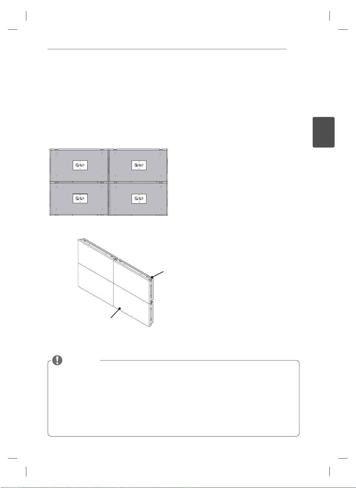
How to Join Sets - Installing Set 4
Loosely mount Set 4 to the wall mount plate or the wall and minimize the space between the sets using
the U-shaped fixtures.
When Set 4 is firmly mounted to the wall, remove the U-shaped fixtures.
Remove the guide brackets. See <How to Join Sets - Installing Set2,3>.
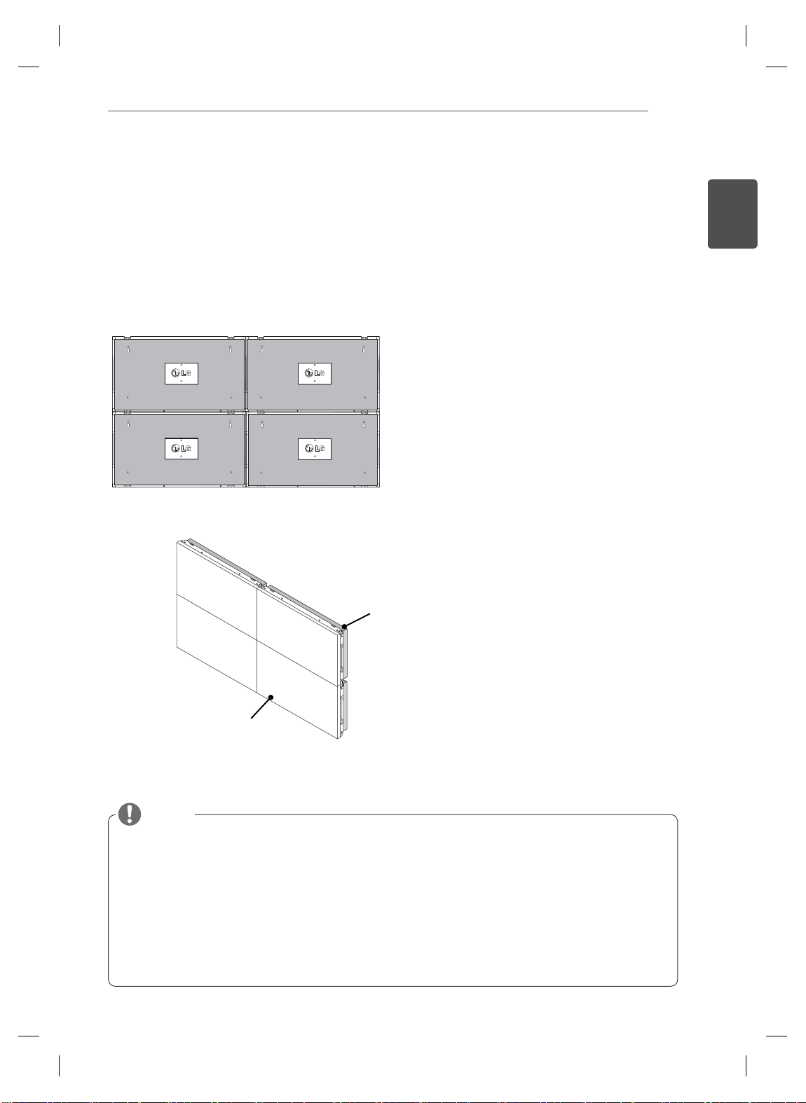
Now the 2 x 2 tiling is complete.
You can tile in various combinations, such as 3 x 3.
Set 4 joined to the rest of the sets
(2 x 2 tiling)
7
ENGLISH
ENG
Wall mount plate or wall
Display set
NOTE
The guide brackets for tiling should only be used to join sets and should be removed once they are joined.
The guide brackets should only be used as the assisting tool when tiling sets. The load applied to each set
should be supported by the wall mount plate or the wall using a VESA wall mount (800 x 400).
(Each set must be firmly mounted to the wall mount plate or the wall.)
The guide brackets must be removed once the sets are joined. When joining the sets without removing the
guide brackets, extra caution is required to prevent damage due to the set weight.
The U-shaped fixtures must also be removed after mounting the set to the wall mount plate or the wall.
You may mount the set without using the guide brackets or the U-shaped fi xtures; this does not affect the
performance of the device.
REMOTE CONTROL
G
E
INPUT
GY
S
G
MARK
C
1
. ,
3
DEF
4
G
5
JKL6MNO
7
PQRS
8
9
0
- * #
C
R
ON
F
MONITOR
MUTE
T
N
POWER
P
A
G
E
INPUT
ENERGY
SAVING
MARK
ARC
ON
OFF
. , !
ABCDEF
GHI
JKLMNO
PQRSTUV
1/a/A
- * #
WXYZ
CLEAR
S.MENU
MONITOR
PSM
AUTO
MUTE
BRIGHT
NESS
MENU
POWER
8
ENGLISH
ENG
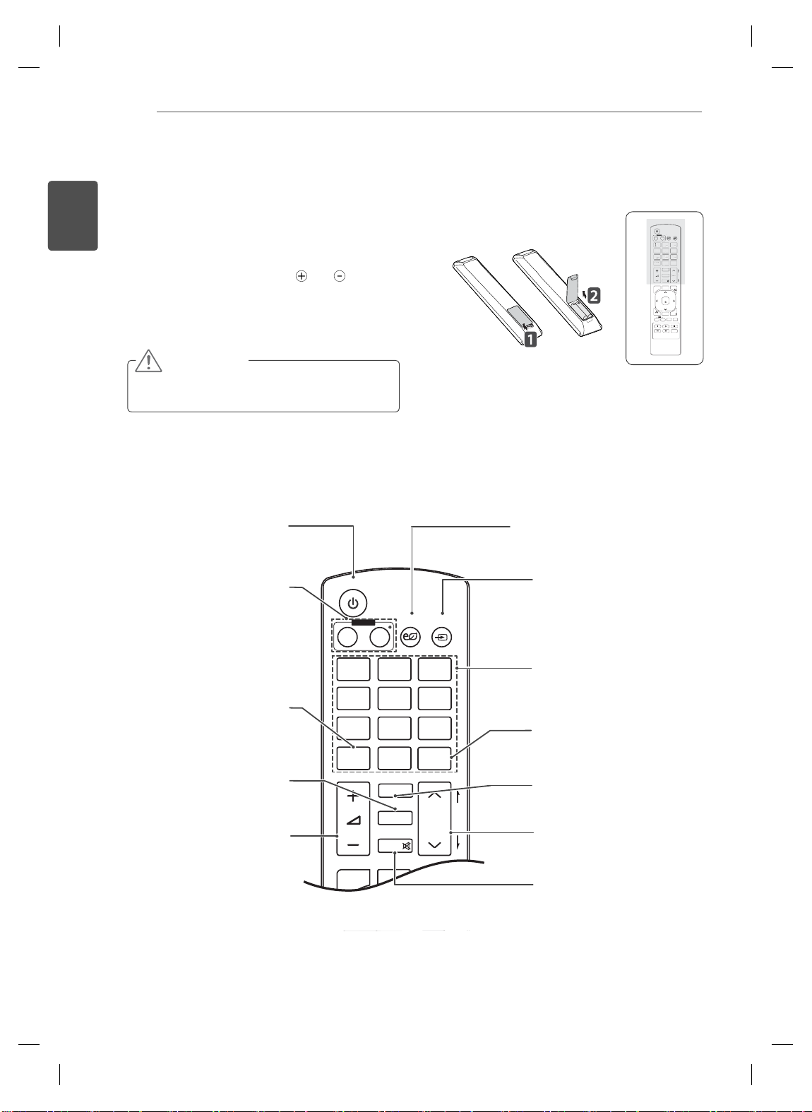
REMOTE CONTROL
The descriptions in this manual are based on the buttons of the remote control. Please
read this manual carefully and use the Monitor set correctly.
To replace batteries, open the battery cover, replace
batteries (1.5 V AAA) matching
label inside the compartment, and close the battery
cover. To remove the batteries, perform the installation
actions in reverse.
CAUTION
Do not mix old and new batteries, as this
may damage the remote control.
Make sure to point the remote control to the remote control sensor on the Monitor set.
Power On / Off
Switches the set on from
standby or off to standby
Turn off the monitor and then
Monitor On / Off
turn it back on.
and ends to the
.
Energy Saving
Adjust the Energy Saving
mode of the SET.
INPUT
If you press the button once, the
following Input Signal Window
will appear. Select the signal
type you want using the button.
POWER
MONITOR
ON
1
. , !2ABC3DEF
!2ABC
4
GHI5JKL6MNO
HI
7
PQRS8TUV
1/a/A
1/a/A
MENU
BACK
ID
ON
INPUT
ENERGY
ENER
OFF
OF
SAVING
AVIN
9
WXYZ
TUV
WXYZ
CLEAR
LEA
0
- * #
MARK
ARC
AR
P
A
BRIGHT
BRIGH
PSM
PSM
G
ESS
NESS
E
MUTE
AUTO
S.MENU
OK
EXIT
TILE
OFF
This button selection is not
Selects the Picture Status
Volume Up/Down
Adjusts the volume.
1/a/A
applicable.
PSM
Mode.
Number and
Alphabet
Type numbers.
The alphabet selection is not
applicable.
Clear
This button selection is not
applicable.
ARC
Selects the Aspect Ratio Mode.
BRIGHTNESS
Moves to the previous or next
screen.
MUTE
Switches the sound on or off.
REMOTE CONTROL
OK
S
U
O
U
ID
CK
TILE
ON
O
E
E
OK
S.MENU
AUTO
MUTE
NESS
MENU
ID
BACK
TILE
ON
OFF
EXIT
POWER
MONITOR
OFF
ON
1
. , !2ABC3DEF
4
GHI5JKL6MNO
7
PQRS8TUV
1/a/A
0
MARK
ARC
PSM
MUTE
AUTO
AUT
MENU
MEN
OK
BACK
BA
TILE
ID
OFF
FF
ON
9
INPUT
ENERGY
SAVING
9
WXYZ
CLEAR
- * #
P
A
BRIGHT
G
NESS
E
S.MENU
.MEN
XIT
EXIT
ENGLISH
ENG
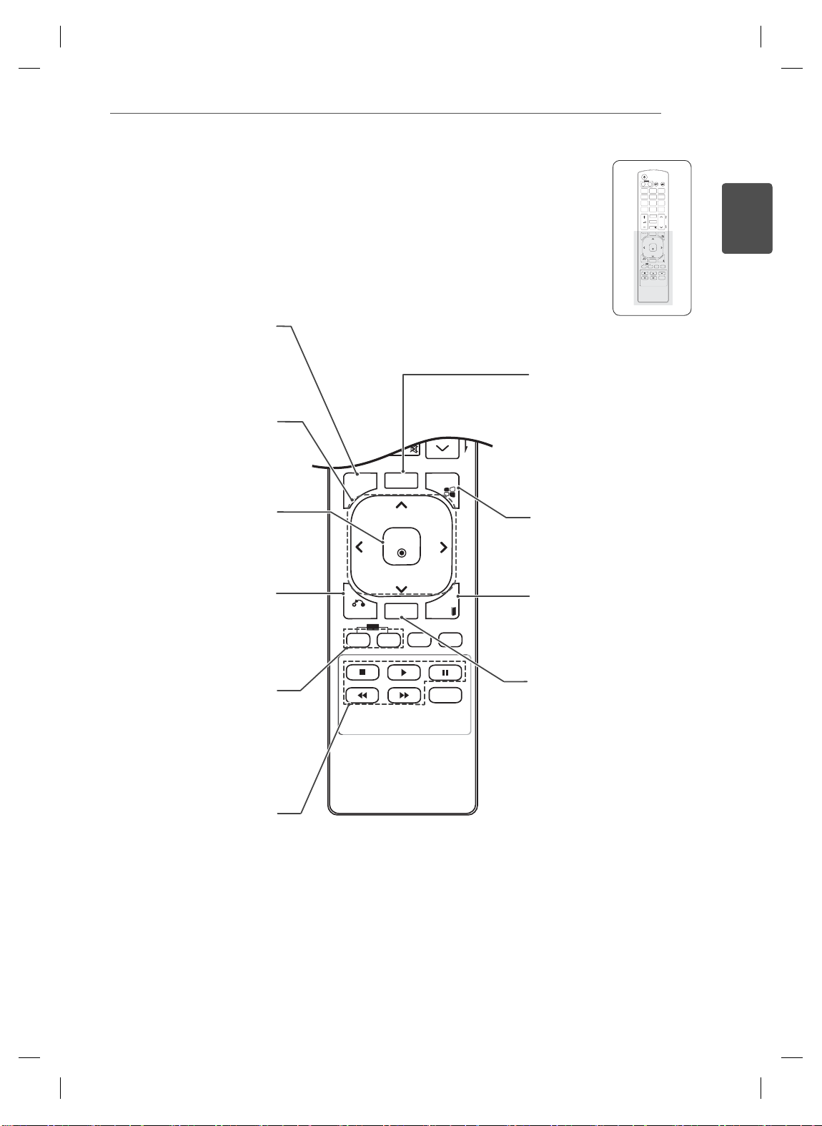
Selects a menu.
MENU
Clears all on-screen displays
and returns to Set viewing
from any menu.
Up/Down/Left/Right
Allows you to navigate the
on-screen menus and adjust
the system settings to your
preference.
OK
Accepts your selection or
displays the current mode.
BACK
Allows the user to move
back one step in an interactive
application.
ID ON/OFF
Allows you to set the Picture
ID or turn it of
f. Use this
button to control the individual
monitors connected in RS-
232C mode. (It works properly
only when Set IDs are
assigned.)
USB Menu control
Controls media playback.
AUT
O
Automatically adjusts picture
position and minimizes image
instability.(RGB input only)
S.MENU
(SuperSign Menu Key)
This button selection is not
applicable.
EXIT
Clears all on-screen displays
and returns to Monitor set
viewing.
TILE
Selects the TILE Mode.
ENGLISH
ENG
USING THE MONITOR SET
10
(8Ω)
SPEAKER
AUDIO
(RGB/DVI)
AUDIO
COMPONENT IN
CONTROL IN
REMOTE
RED
WHITE
RED
BLUE
GREEN
R
L
R
P
B
VIDEO AUDIO
P
RGB OUT
USB LAN
/DVI
DVI OUT DVI IN
(CONTROL)
RS-232C
RGB IN
HDMI OUT
(RGB/DVI)
AUDIO
DVI OUT
AUDIO OUT
RGB OUT
REMOTE
AUDIO OUT
CONTROL IN
USING THE MONITOR SET
INPUT
ENERGY
SAVING
ON
OFF
. , !ABCDEF
MONITOR
POWER
11
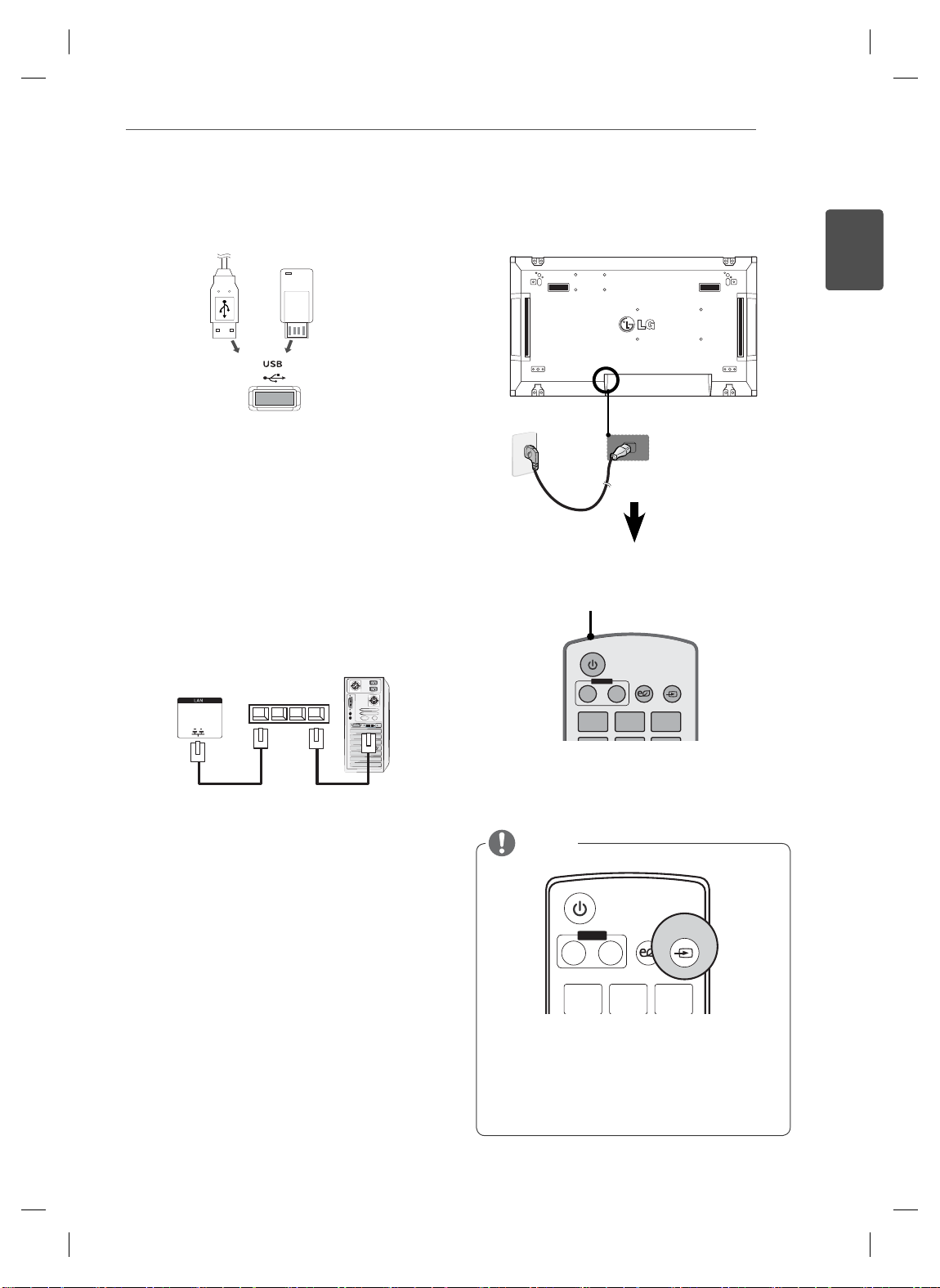
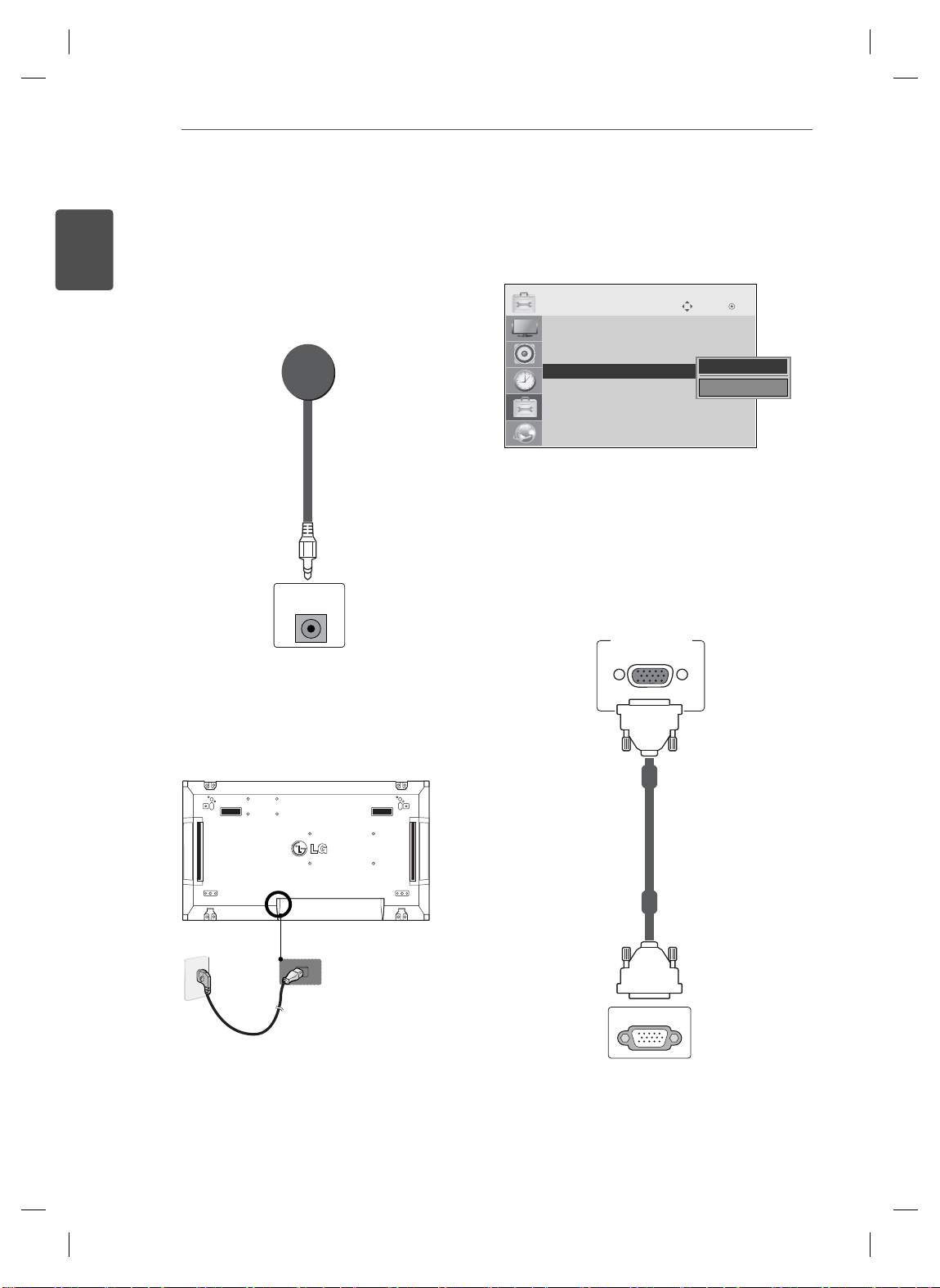
Connecting to a USB Connecting the Power code
or
2
1
Connecting to the LAN
LAN connection
Using a router(Switching Hub)
A
Power button
ENGLISH
ENG
LAN
Using the Internet.
B
Product
Switching Hub
PC
NOTE
POWER
INPUT
MONITOR
OFFON
123
.,!
Select an input signal.
Component ➙ RGB ➙ HDMI ➙ DVI-D
※
If you want to use HDMI-PC mode, you must
set the input label to PC mode.
INPUTENERGY
SAVING
ABC DEF
MAKING CONNECTIONS
12
ENGLISH
ENG
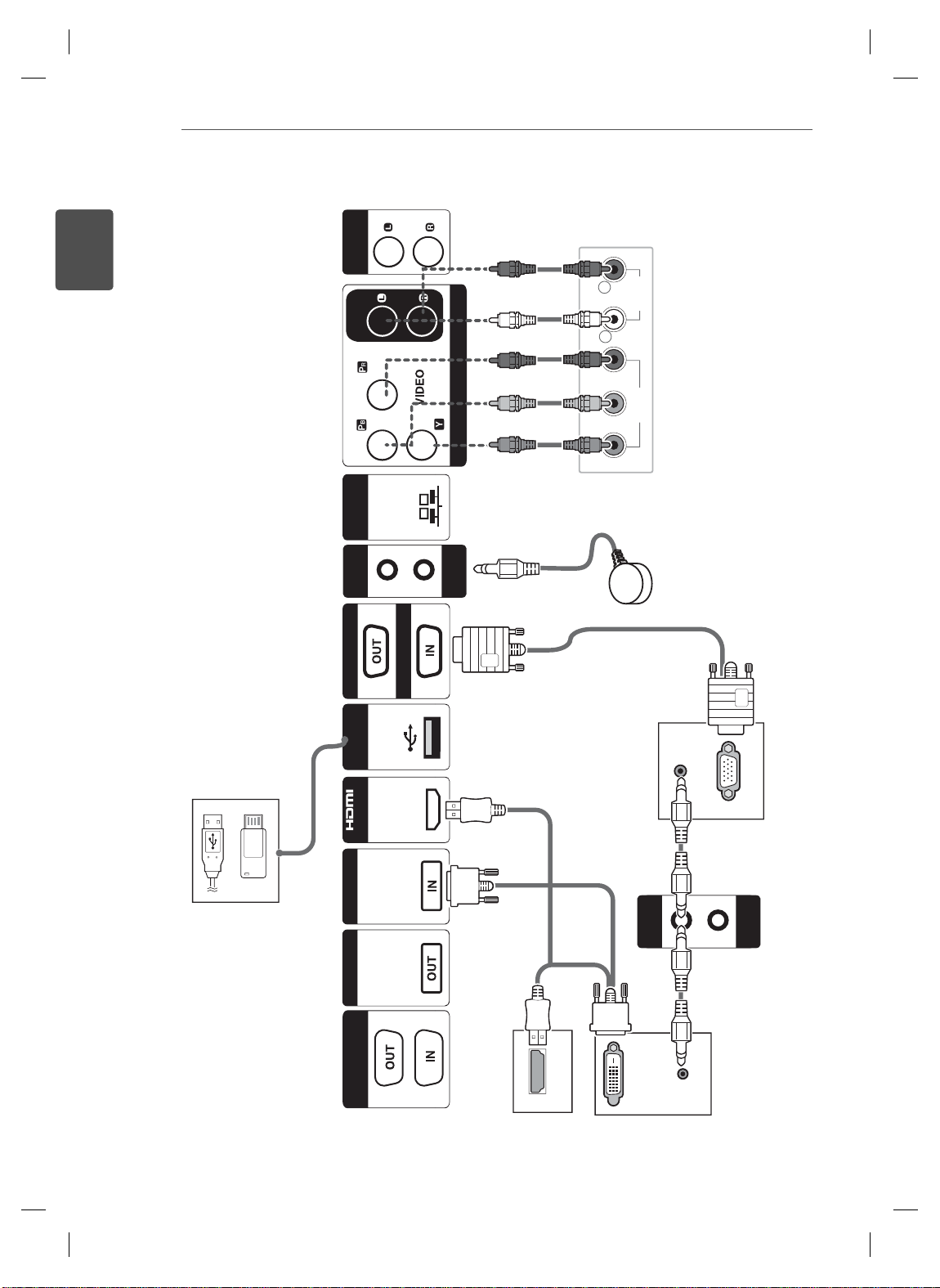
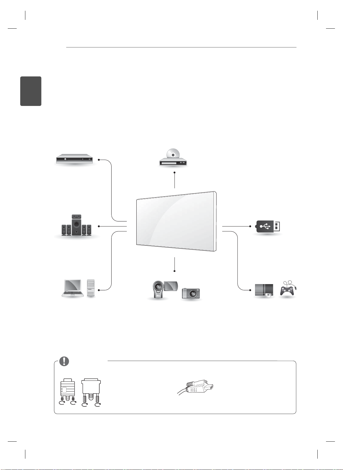
MAKING CONNECTIONS
Connect various external devices to the ports on the Monitor set’s back panel.
Find an external device you want to connect to your Monitor set shown on the following illustration.
1
Check the connection type of the external device.
2
Go to the appropriate illustration and check the connection details.
3
HD Receiver
HDMI
Component
Speaker
DVD
HDMI
Component
USB
Memory storage
Memory card reader
HDMI
DVI
RGB
RGB
PC
NOTE
DVI
Camcorder/Camera
HDMI
Component
Connect the signal
input cable and tighten
it by turning the screws
clockwise.
Gaming device
HDMI
Component
When connecting an HDMI
cable as illustrated, remove
the screw on the HDMI
connector first.
MAKING CONNECTIONS
DVI-INDVI-OUT DVI-INDVI-OUTDVI-INDVI-OUT
13
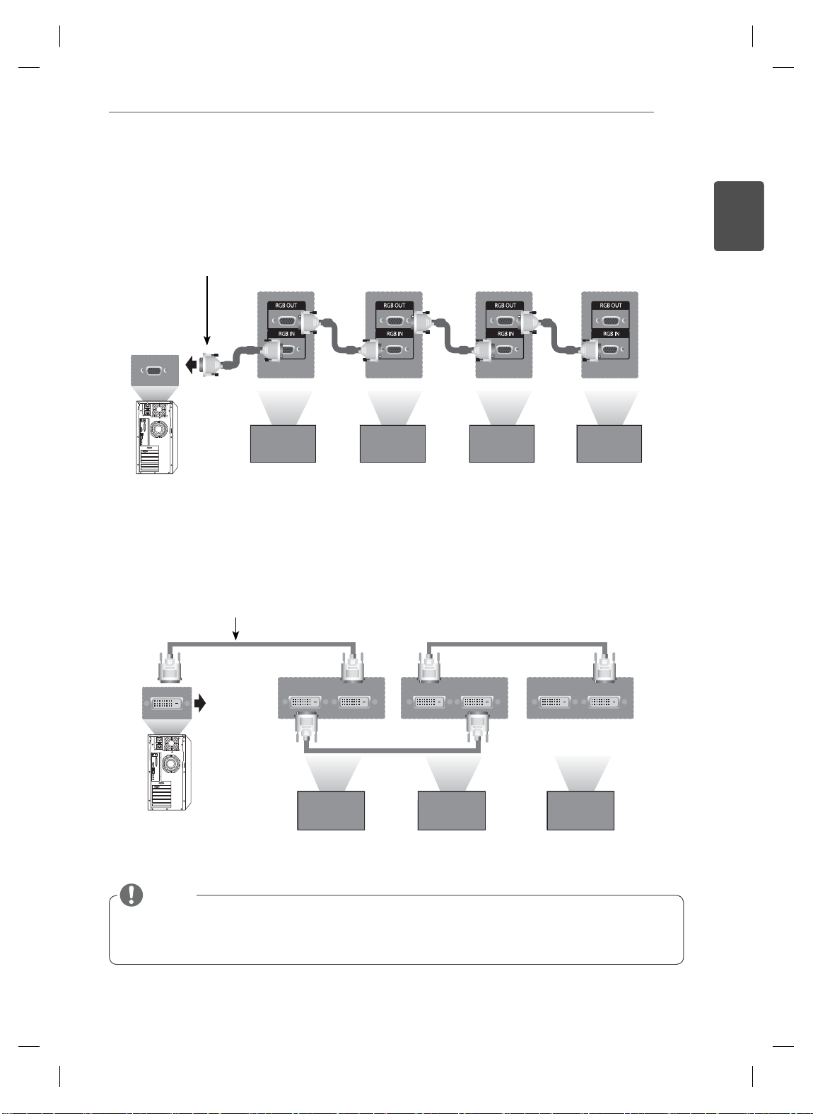
Daisy Chain Monitors
RGB Cable
15-pin D-Sub Signal Cable
(Max 3m)
DVI Cable
ENGLISH
ENG
DVI Cable
(Max 3m)
NOTE
When multi-connecting in/out cascade format, no loss cables are recommended.
Since the image quality may decrease when multiple monitors are connected, we recommend that
you use an amplifier.
ENTERTAINMENT
14
ENGLISH
ENG
MULTIVISION CONFIGURATION
Set ID setup for each set.
Function Setting
IR Receiver connection.
1
REMOTE
CONTROL IN
3
OPTION
• Menu Language
• ISM Method : Normal
• Factory Reset
• Set ID
• Tile Mode
AN
• F
• Product/Service Info.
IR Receiver removal for all sets except for Set 1.
4
RGB connection.
5
Move OK
◀ 1 ▶
Close
PC
Connecting the Power code
2
2
1
RGB IN
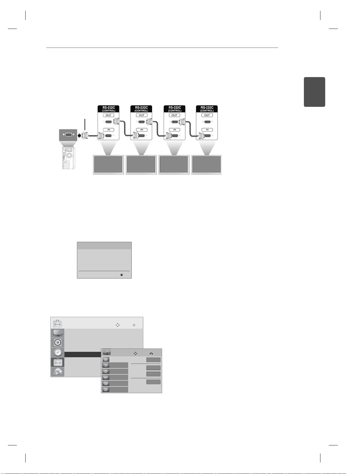
Connect the Monitor sets, in series, using an RS-232C cable.
T
6
RS-232C Cable
(not included)
ENTERTAINMENT
15
ENGLISH
ENG
PC
Installation Menu setup.
7
Installation Menu (V 2.21)
LG Digital Signage Setup
White Balance Adjust
Password Change
MCU Version V2.00.0 OK
Tile Mode setup.
8
OPTION
• Menu Language
• ISM Method : Normal
• Factory Reset
• Set ID
ꔋ
• Tile Mode
• FAN
• Product/Service Info.
Set 1 Set 2 Set 3 Set 4
Move OK
Tile
Tile Mode
Auto Config.
Position
Size
Natural
Reset
Move Prev.
Tile Mode
Row
Colunm
Tile ID
◀
▶
Off
2
2
1
ENTERTAINMENT
16
ENGLISH
ENG
Setting the Installation Menu
If you press the MENU button on the remote
1
control for more than five seconds, the main
menu appears and then disappears. The input
data is also displayed in the upper left corner of
the screen.
RGB
Press the "0" button four times. Press the OK
2
button.
1
. , !2ABC3DEF
4
GHI5JKL6MNO
7
9
PQRS8TUV
WXYZ
1/a/A
CLEAR
0
- * #
15Min Force
Off
Turns off the monitor if there is no
input for more than 15 minutes.
"No" is the recommended default
value setting.
4 hours off Turns off the monitor if there is no
input on the remote control for more
than four hours.
"No" is the recommended default
value setting.
Wake On LAN Turns on the monitor remotely using
LAN.
Total Set ID Sets the maximum value for picture
IDs.
DPM Enters energy saving mode if there is
no input signal.
Software
Update
Sets whether to use NSU (Network
Software Update).
When the Installation Menu is displayed, select
3
the item you want.
Installation Menu (V 2.21)
LG Digital Signage Setup
White Balance Adjust
Password Change
MCU Version V2.00.0 OK
LG Digital Signage Setup
• 15 Min Force Off
• 4 Hours Off
• Wake On LAN
• Total Set ID
• DPM
• Software Update
Previous ● OK
◄ Yes ►
◄ Yes ►
◄ Yes ►
◄ 1 ►
◄ Yes ►
◄ No ►
ENTERTAINMENT
ID 1
ID 2
ID 3
ID 4
ID 1
ID 2
ID 4
ID 5
ID 3
ID 6
ID 7
ID 8
ID 9
ID 1
ID 2
ID 5
ID 6
ID 3
ID 7
ID 9
ID 10
ID 11
ID 4
ID 8
ID 12
ID 13
ID 14
ID 15
ID 16
ID 1
ID 2
T
17
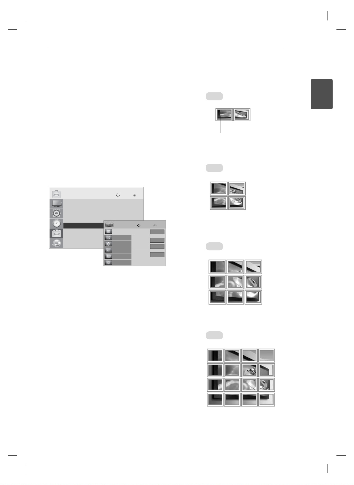
Setting the Tile Mode
In Tile Mode you can view an image in a larger
scale by connecting multiple monitors.
Tile Mode Off: An input image is not
enlarged, and the same image is shown
on all connected monitors.
Tile Mode On: An input image is
enlarged according to the value in the H.
Set Count and V
OPTION
• Menu Language
• ISM Method : Normal
• Factory Reset
• Set ID
ꔋ
• Tile Mode
• FAN
• Product/Service Info.
. Set Count fields.
Move OK
Tile
Tile Mode
Auto Config.
Position
Size
Natural
Reset
Tile Mode
Row
Colunm
Tile ID
Move Prev.
◀
Off
2
2
1
ENGLISH
ENG
• 2X1:
When using two monitors
ID 2
ID 1
Tile ID
ID 1
ID 3
ID 1
ID 2
ID 2
ID 4
ID 3
• 2X2:
When using four monitors
▶
• 3X3:
When using nine monitors
ID 4
ID 7
ID 5
ID 8
• 4X4:
When using 16 monitors
ID 1
ID 2
ID 5
ID 9
ID 13
ID 6
ID 10
ID 14
ID 11
ID 15
ID 3
ID 7
ID 6
ID 9
ID 4
ID 8
ID 12
ID 16
ENTERTAINMENTENTERTAINMENT
1
2
3
4
Off
Close
IR Receiver
RS232C
1
2
3
4
1
2
3
4
Off
Close
Off
Close
IR Receiver
RS232C
ID
BACK
TILE
ON
OFF
EXIT
18
ENGLISH
ENG
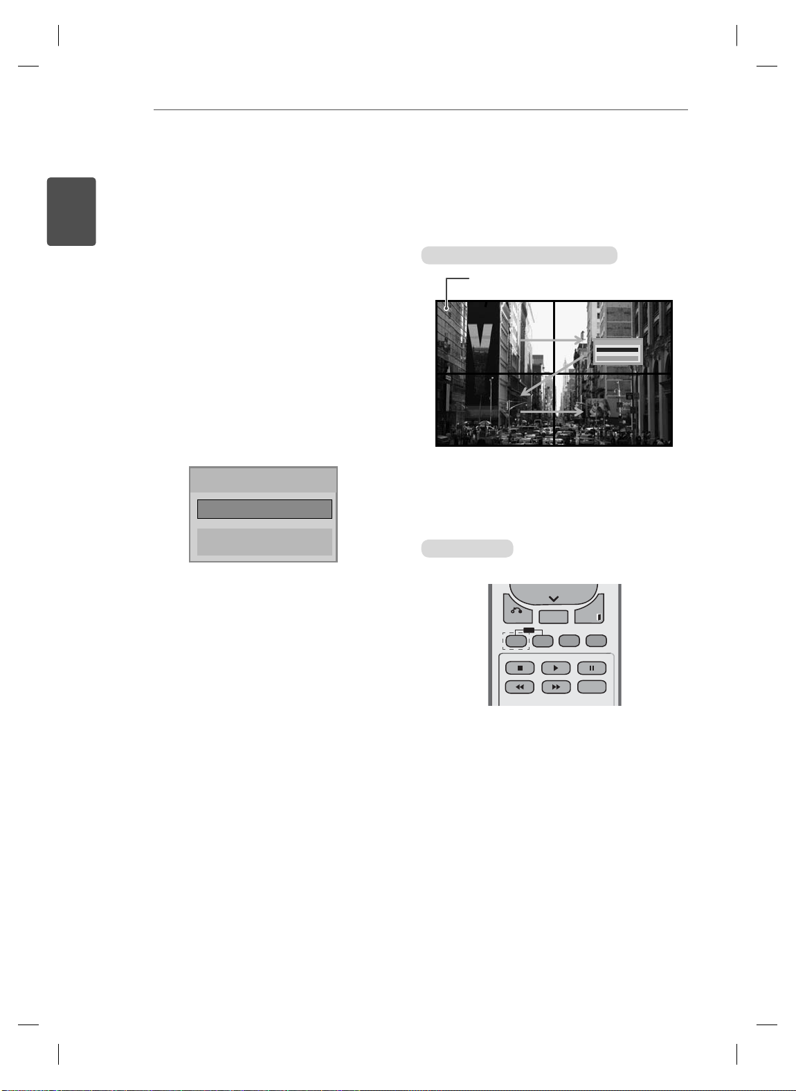
Setting the Picture ID
The Picture ID menu allows you to control all sets using the IR Receiver connected to Set 1.
The IR signal of the remote control is
transmitted through the RS232C cables
connected in serial mode.
When you set a Picture ID using the
remote control, you can only control the
Set that matches the Picture ID.
ex) For example, if you set a Picture ID to
2, you can only control the monitor with
the Set ID 2.
If Picture ID is set to Off, you can control
all monitors at the same time.
Picture ID
◀
Off
Close
▶
2X2 Multi-Vision (Total Set ID: 4)
IR Receiver
RS232C
RS232C
Picture ID button
Picture ID
Picture ID
Picture ID
Off
Off
Off
Close
Close
Close
Picture ID is set according to the
Total Set ID set in
the Installation Menu.


Easy Setup Guide
MONITOR PRO
ČESKY
REKLAMNÍ PANELY
Před uvedením zařízení do provozu si pečlivě prostudujte tento návod a uložte jej pro budoucí potřebu.
MODELY MONITORŮ PRO REKLAMNÍ PANELY
47WV30
www.lg.com
ČESKY
CS
MONTÁŽ A PŘÍPRAVA
2
MONTÁŽ A PŘÍPRAVA
Vybalení
Zkontrolujte, zda produkt obsahuje následující položky. Pokud některé příslušenství chybí, obraťte se na
místního prodejce, od něhož jste produkt zakoupili. Vyobrazení v tomto návodu se může lišit od skutečného
produktu nebo příslušenství.
CD (Návod k obsluze) /
karta
POWER
INPUT
ENERGY
MONITOR
OFF
ON
SAVING
. , !ABCDEF
GHIJKLMNO
PQRSTUV
WXYZ
1/a/A
CLEAR
- * #
MARK
ARC
P
A
BRIGHT
PSM
G
NESS
E
MUTE
AUTO
S.MENU
MENU
OK
EXIT
BACK
TILE
ID
OFF
ON
Dálkový ovladač a baterie
Napájecí kabel Kabel DVI
Přijímač IR Vodicí lišta
Šroub M4 x 10L
(4ea)
Držák napájecího
Kabel RGB
Šroub M6
(4ea)
Úchyt ve tvaru U
Feritové jádro
Držák kabelu
(2ea)
kabelu
UPOZORNĚNÍ
Nepoužívejte jiné než schválené položky, jinak není zaručena bezpečnost a životnost produktu.
Záruka se nevztahuje na poškození a zranění způsobená neschválenými položkami.
POZNÁMKA
Příslušenství dodané se zařízením se může v závislosti na modelu lišit.
Technické údaje produktu nebo obsah v tomto návodu se mohou za účelem zlepšení funkcí produktu
změnit bez předchozího upozornění.

Rozměry (šířka × výška × hloubka) / hmotnost
H
MONTÁŽ A PŘÍPRAVA
3
W
1047 mm × 592 mm × 91,1 mm / 29 kg
D
Zobrazení uživatelské příručky
„Vložení disku CD-ROM“ do počítače
CD-ROM se otevře automaticky.(pouze v systému Window)
Tento počítač ➙ Digital_LG(CD-ROM) ➙ Otevřete Index.htm
Tento počítač ➙ Digital_LG(CD-ROM) ➙ Složka s návodem ➙ Otevřete uživatelskou příručku
ČESKY
CS
MONTÁŽ A PŘÍPRAVA
4
ČESKY
CS
Odstranění L-lišt před
instalací
Před instalací monitoru odstraňte z každého rohu
L-lišty.
POZNÁMKA
Odstraněné L-lišty si ponechte a použijte je
při dalším přesouvání monitoru.
Stěna z monitorů
Propojení monitorů – Instalace
monitoru 1
*Příklad stěny 2 x 2
Čísla přiřazená v tomto příkladu (č. 1, č. 2,
č. 3, č. 4) jsou použita pro demonstraci postupu instalace z důvodu jejího zjednodušení. Tato č
fikačním číslem TV, které se používá pro dálkové ovládání.
S pomocí šroubů nainstalujte vodicí lištu do
drážky pro lištu a připevněte monitor k desce
pro montáž na stěnu nebo ke stěně.
ísla nemají nic společného s Identi-
Vodicí lišta
Deska pro montáž na stěnu
UPOZORNĚNÍ
Pokud připojíte více monitorů pro vícená-
sobné zobrazení, nemusí mít obrazovky
monitorů stejnou barvu na všech monitorech. Pokud chcete ručně přizpůsobit barvu
obrazovky
stala
Při instalaci více monitorů na zeď připevně-
te ke všem monitorům přijímač IR nebo pro
připojení použijte kabel RS-232C a přijímač
IR připevněte k prvnímu monitoru.
, více informací naleznete v in-
ční příručce.
<Zadní pohled na televizor s deskou pro montáž na stěnu>
Šrouby pro upevnění
držáku na stěnu VESA
Vodicí lišta
Šrouby pro připevně-
ní vodicí lišty
Deska pro montáž
na stěnu
Deska pro montáž na stěnu je pro zvýrazně-
ní zobrazena šedě.
MONTÁŽ A PŘÍPRAVA
5
Propojení panelů – Instalace
panelu 2
Spojte monitor 2 a 1 pomocí vodicích lišt
v horní části monitoru 1 a připevněte oba
monitory k desce pro montáž na stěnu nebo
stěně.
Po připevnění monitorů demontujte vodicí liš-
ty.
<Monitory spojené pomocí vodicích lišt>
Vodicí lišta
<Zadní pohled na televizor s deskou
pro montáž na stěnu>
Postup vyjmutí vodicích lišt
Vyšroubujte šrouby zajišťující vodicí lištu ze
zadní strany monitoru a vyjměte vodicí lištu.
Po demontáži šroubů vodicí lišta sjede dolů.
Potom je třeba ji vyjmout bočním otvorem.
Lze to provést pouze v případě, že je na de-
montáž šroubů dostatek místa mezi monitorem a deskou pro montáž na stěnu nebo stěnou. (Před připevněním vodicích lišt se ujistěte, že je na demontáž šroubů dostatek místa.)
ČESKY
CS
<Monitory po demontáži vodicích lišt>
<Vyjmutí vodicí lišty bočním otvorem>
Odstraňte
vodicí lišty.
ČESKY
CS
MONTÁŽ A PŘÍPRAVA
6
Propojení monitorů – Instalace monitoru 3
Podle předchozích kroků připevněte vodicí lišty k monitoru 3 a volně upevněte monitor k desce pro montáž
na stěnu nebo stěně.
#2
#1 #3
<Spojené monitory 1 a 2> <Připojuje se monitor 3>
Minimalizujte vzdálenost mezi stranami monitorů pomocí úchytů ve tvaru U.
Jakmile budou monitory spojeny s minimální vůlí, napevno je připevněte k desce pro montáž na stěnu nebo
stěně.
Potom, co napevno připevníte monitory ke stěně, demontujte úchyty ve tvaru U.
Úchyt ve tvaru U
Úchyt ve tvaru U
MONTÁŽ A PŘÍPRAVA
Propojení monitorů – Instalace monitoru 4
Volně připevněte monitor 4 k desce pro montáž na stěnu nebo stěně a minimalizujte rozestupy mezi moni-
tory pomocí úchytů ve tvaru U.
Jakmile napevno připevníte monitor 4 ke stěně, demontujte úchyty ve tvaru U.
Odstraňte vodicí lišty. Viz část <Propojení monitorů – Instalace monitoru2,3>.
Nyní je montáž stěny 2 x 2 dokončena.
Monitory můžete spojovat i v jiných kombinacích, například 3 x 3.
Monitor 4 spojený s ostatními monitory
(stěna 2 × 2)
7
ČESKY
CS
Deska pro montáž na stěnu nebo stěna
Monitor
POZNÁMKA
Vodicí lišty pro vytvoření stěny z panelů jsou určeny pouze ke spojení monitorů a po spojení je třeba je demontovat.
Vodicí lišty slouží pouze jako pomůcka pro sestavení stěny z monitorů. Váha jednotlivých monitorů by měla být ne-
sena deskou pro montáž na stěnu nebo stěnou za použití montážní desky VESA (800 × 400).
(Každý monitor musí být pevně připevněn k desce pro montáž na stěnu nebo ke stěně.)
Po spojení monitorů je třeba demontovat vodicí lišty. Při připojování televizorů bez odstranění vodicích lišt, je nutné
věnovat zvýšenou pozornost prevenci poškození z důvodu hmotnosti televizoru.
Po připevnění monitorů k desce pro montáž na stěnu nebo stěně je třeba rovněž demontovat úchyty ve tvaru U.
Monitory lze rovněž připevnit bez pomoci vodicích lišt nebo úchytů ve tvaru U, které nemají vliv na funkci výrobku.

DÁLKOVÝ OVLADAČ
G
E
INPUT
GY
S
G
MARK
C
1
. ,
3
DEF
4
G
5
JKL6MNO
7
PQRS
8
9
0
- * #
C
R
ON
F
MONITOR
MUTE
T
N
POWER
P
A
G
E
INPUT
ENERGY
SAVING
MARK
ARC
ON
OFF
. , !
ABCDEF
GHIJKLMNO
PQRSTUV
1/a/A
- * #
WXYZ
CLEAR
S.MENU
MONITOR
PSM
AUTO
MUTE
BRIGHT
NESS
MENU
POWER
8
DÁLKOVÝ OVLADAČ
ČESKY
CS
Popisy v tomto návodu se týkají tlačítek dálkového ovladače. Prostudujte si pozorně
tento návod, abyste monitor správně používali.
Pokud chcete provést výměnu baterií, otevřete kryt baterie, vložte baterie (1,5 V typu AAA) tak, aby koncovky
a odpovídaly štítku umístěnému uvnitř prostoru
pro baterie, poté kryt baterií zavřete.
Při vyjímání baterií proveďte stejný postup v opačném
pořadí.
UPOZORNĚNÍ
Nepoužívejte současně staré a nové baterie,
jinak se dálkový ovladač může poškodit.
Dálkový ovladač musíte namířit na čidlo dálkového ovládání na monitoru.
Power On / Off
(Zapnutí/Vypnutí)
Umožňuje zapnout monitor z pohotovostního režimu
nebo jej vypnout do pohoto-
vostního režimu.
Monitor On/Off
(Monitor Zap./Vyp.)
Vypněte monitor a potom jej
opět zapněte.
1/a/A
T
čítko je nefunkční.
oto tla
Energy Saving (Úspora energie)
Slouží k nastavení režimu úspory
energie monitoru.
INPUT (VSTUP)
Pokud stisknete tlačítko jednou, objeví se následující okno
vstupního signálu. Pomocí tlačítka vyberte požadovaný typ
signálu.
Number and Alphabet (Tlačítka s čísly a abecedou)
Zadávejte čísla.
Zadávání písmen není k dispozici.
POWER
MONITOR
ON
1
. , !2ABC3DEF
!2ABC
4
GHI5JKL6MNO
HI
7
PQRS8TUV
1/a/A
1/a/A
MENU
BACK
ID
ON
INPUT
ENERGY
ENER
OFF
OF
SAVING
AVIN
9
WXYZ
TUV
WXYZ
CLEAR
LEA
0
- * #
MARK
ARC
AR
P
A
BRIGHT
BRIGH
PSM
PSM
G
ESS
NESS
E
MUTE
AUTO
S.MENU
OK
EXIT
TILE
OFF
Clear (Smazat)
Toto tlačítko je nefunkční.
Vybere režim Picture Status
(Tlačítko pro zvýšení/sníže-
(Stav obrázku).
Volume Up/Down
Upraví hlasitost.
ní hlasitosti)
PSM
ARC
Vybere režim poměru stran.
BRIGHTNESS (JAS)
Přechod na předchozí nebo
další obrazovku.
MUTE (VYPNOUT ZVUK)
Zapne a vypne zvuk.

OK
S
U
O
U
ID
CK
TILE
ON
O
E
NESS
MENU
Vybere menu.
Zavře všechna menu na ob-
razovce a z libovolného
menu přejde zpět na sledo-
vání monitoru.
Up/Down/Left/Right (Naho-
ru/Dolů/Doleva/Doprava)
Umožňuje procházet menu na
obrazovce a přizpaůsobit na-
stavení systému podle vašich
potřeb.
OK
Potvrdí vaši volbu nebo zob-
razí aktuální režim.
MENU
MUTE
AUTO
OK
S.MENU
DÁLKOVÝ OVLADAČ
POWER
MONITOR
ON
1
. , !2ABC3DEF
4
GHI5JKL6MNO
7
PQRS8TUV
1/a/A
MENU
MEN
BACK
BA
ON
9
INPUT
ENERGY
OFF
SAVING
9
WXYZ
CLEAR
0
- * #
MARK
ARC
P
A
BRIGHT
PSM
G
NESS
E
MUTE
AUTO
AUT
S.MENU
.MEN
OK
XIT
EXIT
TILE
ID
OFF
FF
ČESKY
CS
AUTO (AUTOMATICKY)
Automatické přizpůsobení polohy obrazu a eliminace nestability obrazu (pouze vstup
E
RGB).
S.MENU
(Tlačítko menu SuperSign)
Toto tlačítko je nefunkční.
Umožňuje uživateli pohyb
BACK (ZPĚT)
zpět o jeden krok v interaktiv-
ní aplikaci.
ID ON/OFF
(ZAPNUTÍ/VYPNUTÍ ID)
Umožňuje nastavení Pictu-
re ID (ID obrázku) nebo jeho
vypnutí. T
oto
tlačítko slouží
k ovládání jednotlivých moni-
torů připojených v režimu RS-
232C. (Funguje správně pou-
ze v případě, že jsou přiřaze-
na Identifikační čísla TV.)
USB Menu control
(Ovládání menu USB)
Ovládají přehrávání médií.
BACK
ON
EXIT
TILE
ID
OFF
Vymaže veškeré obrazovky
menu na obrazovce a vrátí se
ke sledování monitoru z jakéhokoli menu.
TILE (DLAŽDICE)
Vybere režim TILE (DLAŽDICE).
EXIT (UKONČIT)

POUŽÍVÁNÍ MONITORU
10
ČESKY
CS
(8Ω)
SPEAKER
AUDIO
(RGB/DVI)
AUDIO
RGB OUT
RGB IN
COMPONENT IN
CONTROL IN
REMOTE
RED
WHITE
RED
BLUE
GREEN
R
L
R
P
B
VIDEO AUDIO
P
USB LAN
/DVI
DVI OUT DVI IN
(CONTROL)
RS-232C
HDMI OUT
(RGB/DVI)
AUDIO
DVI OUT
AUDIO OUT
RGB OUT
REMOTE
AUDIO OUT
CONTROL IN

POUŽÍVÁNÍ MONITORU
Připojení k portu USB Připojení napájecího kabelu
11
nebo
Připojení k síti LAN
Připojení sítě LAN
Pomocí směrovače (přepínacího rozbočovače)
A
LAN
Produkt
Přepínací
rozbočovač
PC
2
1
Tlačítko Napájení
POWER
ENERGY
MONITOR
OFF
ON
SAVING
. , !ABCDEF
ČESKY
CS
INPUT
Pomocí připojení k Internetu.
B
POZNÁMKA
POWER
INPUT
MONITOR
OFFON
123
.,!
Vyberte vstupní signál.
Component ➙ RGB ➙ HDMI ➙ DVI-D
※
Chcete-li používat režim HDMI-PC, musíte
nastavit označ
ení vstupu na režim PC.
INPUTENERGY
SAVING
ABC DEF

ČESKY
CS
VYTVÁŘENÍ SPOJENÍ
12
VYTVÁŘENÍ SPOJENÍ
K portům na zadním panelu monitoru lze připojit různá externí zařízení.
Externí zařízení, které chcete připojit k monitoru, najděte podle následujícího vyobrazení.
1
Zkontrolujte typ připojení externího zařízení.
2
Přejděte na příslušné vyobrazení a zkontrolujte podrobné údaje o připojení.
3
HD Receiver
HDMI
Komponentní
Speaker
PC
HDMI
DVI
RGB
DVD
HDMI
Komponentní
Camcorder/Camera
HDMI
Komponentní
USB
Paměťové úložiště
Čtečka paměťových
karet
Gaming device
HDMI
Komponentní
POZNÁMKA
RGB
DVI
Připojte kabel vstupního
signálu a utáhněte jej otá-
čením šroubů ve směru
hodinových ručiček.
Před připojením kabelu
HDMI (viz obrázek) povolte
šroub na konektoru HDMI.

Sériové zapojení monitorů
Kabel RGB
15kolíkový signálový kabel D-Sub
(maximálně 3 m)
VYTVÁŘENÍ SPOJENÍ
13
ČESKY
CS
Kabel DVI
Kabel DVI
(maximálně 3 m)
DVI-INDVI-OUT DVI-INDVI-OUTDVI-INDVI-OUT
POZNÁMKA
Při postupném zapojení monitorů se doporučuje používat bezeztrátové kabely.
Protože se kvalita obrazu může při připojení několika monitorů snížit, doporučujeme používat
zesilovač.

ČESKY
CS
ZÁBAVA
14
KONFIGURACE VÍCENÁSOBNÉHO ZOBRAZENÍ
Nastavení identifikačního čísla TV pro každý
Slouží k nastavení funkce
Připojení přijímače IR.
1
REMOTE
CONTROL IN
3
monitor.
OPTION
• Menu Language
• ISM Method : Normal
• Factory Reset
ꔋ
• Set ID
• Tile Mode
AN
• F
• Product/Service Info.
Odstranění přijímače u všech monitorů kromě
4
Monitoru 1.
Připojení RGB.
5
Move OK
◀ ▶
1
Close
Připojení napájecího kabelu
2
2
1
PC
RGB IN

Monitory sériově připojte pomocí kabelu RS-232C.
T
6
ZÁBAVA
15
Kabel rozhraní RS-232C
(není součástí balení)
PC
Monitor 1 Monitor 2 Monitor 3 Monitor 4
Nastavení instalačního menu.
7
Installation Menu (V 2.21)
LG Digital Signage Setup
White Balance Adjust
Password Change
MCU Version V2.00.0 OK
ČESKY
CS
Nastavení režimu Tile (Dlaždice).
8
OPTION
• Menu Language
• ISM Method : Normal
• Factory Reset
• Set ID
ꔋ
• Tile Mode
• FAN
• Product/Service Info.
Move OK
Tile
Tile Mode
Auto Config.
Position
Size
Natural
Reset
Move Prev.
Tile Mode
Row
Colunm
Tile ID
◀
▶
Off
2
2
1

ČESKY
CS
ZÁBAVA
16
Nastavení instalačního menu
Pokud podržíte tlačítko MENU na dálkovém
1
ovládání stisknuté déle než pět sekund, zobrazí se hlavní menu a poté zase zmizí. Vstupní
data se také zobrazí v levém horním rohu obrazovky.
RGB
Stiskněte čtyřikrát tlačítko 0. Stiskněte tlačítko
2
OK.
1
. , !2ABC3DEF
4
GHI5JKL6MNO
7
9
PQRS8TUV
WXYZ
1/a/A
CLEAR
0
- * #
15 Min Force Off (Nucené vypnutí po
15 min)
4 Hours Off
(Vypnutí po 4 h)
Vypne monitor, pokud během 15 minut nezadáte žádný vstup.
Doporučená výchozí hodnota je „No“
(Ne).
Vypne monitor, pokud pomocí dálkového ovládání nezadáte žádný vstup
déle než 4 hodiny.
Doporučená výchozí hodnota je „No“
(Ne).
Wake On LAN
(Aktivace sítě
Zapne monitor vzdáleně pomocí sítě
LAN.
LAN)
Total Set ID
(Identif. číslo
Nastaví maximální hodnotu pro picture IDs (ID obrázků).
TV)
DPM Přejde do režimu úspory energie, po-
kud televizor nepřijme žádný vstupní
signál.
Software Update (Aktualizace
softwaru)
Nastavuje, zda bude použita technologie NSU (Network Software Update).
Jakmile se zobrazí instalační menu, vyberte
3
požadovanou položku.
Installation Menu (V 2.21)
LG Digital Signage Setup
White Balance Adjust
Password Change
MCU Version V2.00.0 OK
LG Digital Signage Setup
• 15 Min Force Off
• 4 Hours Off
• Wake On LAN
• Total Set ID
• DPM
• Software Update
Previous ● OK
◄ Yes ►
◄ Yes ►
◄ Yes ►
◄ 1 ►
◄ Yes ►
◄ No ►

Nastavení režimu Tile (Dlaždice)
ID 1
ID 2
ID 4
ID 5
ID 3
ID 6
ID 7
ID 8
ID 9
ID 1
ID 2
ID 5
ID 6
ID 3
ID 7
ID 9
ID 10
ID 11
ID 4
ID 8
ID 12
ID 13
ID 14
ID 15
ID 16
ID 1
ID 2
T
ID 1
ID 2
ID 3
ID 4
ZÁBAVA
17
V režimu Tile (Dlaždice) můžete zobrazit obraz ve
větším měřítku připojením více monitorů.
Vypnutý režim Tile (Dlaždice): Vstupní ob-
raz není zvětšený a na všech připojených
monitorech se zobrazí stejný obraz.
Zapnutý režim Tile (Dlaždice): Vstupní ob-
raz je zvětšený na základě hodnoty nastavené v polích H.Set Count (Počet monitorů vodorovně) a V
.Set Count (Počet monitorů svis-
le).
OPTION
• Menu Language
• ISM Method : Normal
• Factory Reset
• Set ID
ꔋ
• Tile Mode
• FAN
• Product/Service Info.
Move OK
Tile
Tile Mode
Auto Config.
Position
Size
Natural
Reset
Move Prev.
Tile Mode
Row
Colunm
Tile ID
◀
Off
2
2
1
• 2 × 1:
Při použití 2 monitorů
ID 2
ID 1
ČESKY
CS
ID dlaždice
• 2 × 2:
Při použití 4 monitorů
ID 3
ID 2
ID 4
ID 1
▶
• 3 × 3:
Při použití 9 monitorů
ID 1
ID 2
ID 3
ID 4
ID 7
• 4 × 4:
Při použití 16 monitorů
ID 1
ID 2
ID 6
ID 5
ID 9
ID 13
ID 10
ID 14
ID 5
ID 8
ID 11
ID 15
ID 3
ID 7
ID 6
ID 9
ID 4
ID 8
ID 12
ID 16

ČESKY
1
2
3
4
Off
Close
IR Receiver
RS232C
1
2
3
4
1
2
3
4
Off
Close
Off
Close
IR Receiver
RS232C
CS
ZÁBAVA
18
Nastavení Picture ID (ID obrázku)
Menu Picture ID (ID obrázku) umožňuje ovládat všechny monitory pomocí přijímače IR připojeného
k Monitoru 1.
Infračervený signál z dálkového ovládání je
přenášen prostřednictvím kabelů RS232C
připojených v sériovém režimu.
Jestliže nastavíte Picture ID (ID obrázku) po-
mocí dálkového ovládání, můžete ovládat
pouze monitor odpovídající Picture ID (ID obrázku).
ex) Pokud například nastavíte Picture ID (ID
obrázku) na hodnotu 2, můžete ovládat pouze monitor s Identi
fi kačním číslem TV 2.
Pokud je možnost Picture ID (ID obrázku)
nastavena na hodnotu Vypnuto, můžete
ovládat všechny monitory současně.
Vícenásobné sledování 2X2 (Celkové Set ID (Identif. číslo TV): 4)
Přijímač IR
RS232C
RS232C
Picture ID
Picture ID
Picture ID
Off
Off
Off
Close
Close
Close
Picture ID
◀
Off
Close
▶
Tlačítko Picture ID (ID obrázku)
BACK
TILE
ID
OFF
ON
EXIT
Picture ID (ID obrázku) se nastavuje na základě
Identifikačního čísla
TV nastaveného v instalač
ním
menu.


Easy Setup Guide
PANTALLA SIGNAGE
Lea este manual atentamente antes de utilizar el monitor y
consérvelo para consultarlo cuando lo necesite.
ESPAÑOL
MODELOS DE PANTALLA SIGNAGE
47WV30
www.lg.com

ESPAÑOL
ESP
MONTAJE Y PREPARACIÓN
2
MONTAJE Y PREPARACIÓN
Desembalaje
Compruebe si se incluyen los siguientes elementos con el producto. Si falta algún accesorio, póngase en
contacto con el distribuidor local donde haya comprado el producto. Las ilustraciones que aparecen en este
manual pueden ser diferentes con respecto al producto y los accesorios reales.
Tarjeta/CD (manual de
usuario)
POWER
INPUT
ENERGY
MONITOR
OFF
ON
SAVING
. , !ABCDEF
GHIJKLMNO
PQRSTUV
WXYZ
1/a/A
CLEAR
- * #
MARK
ARC
P
A
BRIGHT
PSM
G
NESS
E
MUTE
AUTO
S.MENU
MENU
OK
EXIT
BACK
TILE
ID
OFF
ON
Cable de alimentación Cable DVI
Receptor IR Soportes de montaje
Tornillos M4 x 10L
(4 unidades)
Cable RGB
Tornillos M6
(4 unidades)
Anillo de ferrita
Soporte para cable
(2 unidades)
Mando a distancia y pilas
Mordaza para cable
Grapa en forma de U
de alimentación
PRECAUCIÓN
No utilice elementos falsificados para garantizar la seguridad y la vida útil del producto.
Ningún daño o lesión física causados por el uso de elementos falsificados está cubierto por la
garantía.
NOTA
Los accesorios proporcionados con el producto pueden variar en función del modelo.
Las especificaciones del producto o el contenido de este manual pueden modificarse sin previo
aviso debido a la actualización de las funciones del producto.

MONTAJE Y PREPARACIÓN
Dimensiones (ancho x alto x profundidad) / Peso
Al.
3
An.
1047 mm x 592 mm x 91,1 mm / 29 kg
Pr.
Para ver la Guía del usuario
Introduzca el CD-ROM en el PC
El CD-ROM se abrirá automáticamente (solo con Windows)
Mi PC ➙ Digital_LG(CD-ROM) ➙ Index.htm Abrir
Mi ordenador ➙ Digital_LG(CD-ROM) ➙ Carpeta manual ➙ Abrir Guía del usuario
ESPAÑOL
ESP

MONTAJE Y PREPARACIÓN
4
ESPAÑOL
ESP
Retirada de los soportes en
L antes de la instalación
Retire los soportes en L de cada una de las
esquinas del monitor antes de instalarlo.
NOTA
Conserve los soportes en L que ha retirado
y utilícelos cuando traslade el monitor en el
futuro.
Instalación de pantallas en
mosaico
Mosaico de pantallas - instalación
del equipo 1
*Ejemplo de mosaico de 2 x 2
Los números asignados en este ejemplo (1, 2, 3 y
4) se utilizan para demostrar el procedimiento de
instalación, con el fin de garantizar que es sencillo
seguirlo. Estos números no tienen nada que ver
con el Set ID que se utiliza para hacer funcionar
el mando a distancia.
Ajuste el soporte de montaje en la guía de
montaje con tornillos y monte el equipo en la
placa de montaje en pared o en la pared.
Soportes de montaje
PRECAUCIÓN
Cuando conecte el monitor para multivisión,
es posible que el color de la pantalla no
sea el mismo por todo el monitor
ajustar el color de la pantalla manualmente,
consulte el manual de instalación.
Cuando instale varios monitores en una
pared, coloque el receptor de IR en todos
los equipos o bien utilice un cable RS-232C
para conectarlos y
el receptor de IR en el primer equipo.
, a continuación, coloque
. Si desea
Placa de montaje en pared
<Vista trasera del equipo con la placa de
Tornillos para fi jar la montura de pared VESA
Placa de montaje en pared
La placa de montaje en pared aparece
ilustrada en gris para su fácil identificación.
montaje en pared>
Soportes de montaje
Tornillos para fijar el
soporte de montaje

MONTAJE Y PREPARACIÓN
5
Mosaico de pantallas instalación del equipo 2
Una el equipo 2 al equipo 1 con los soportes
de montaje de la parte superior del grupo
1 y monte los dos monitores en la placa de
montaje en pared o a la pared.
Retire los soportes de montaje tras montar
los equipos.
<Monitores unidos con los soportes de
montaje>
Retirada de los soportes de montaje
Quite los tornillos del soporte de montaje
de la parte posterior del equipo y retire los
soportes.
Al quitar los tornillos, caerán los soportes.
Debe retirarlos a través del espacio de los
laterales del equipo.
Sólo podrá hacerlo si existe espacio
suficiente entre el equipo y la placa de
montaje en pared o la pared para quitar
los tornillos. (compruebe que dispone de
espacio suficiente para retirar los tornillos
antes de fijar los soportes de montaje).
ESPAÑOL
ESP
Soportes de
montaje
<Vista trasera del equipo con la placa
de montaje en pared>
<Monitores unidos tras retirar los
soportes de montaje>
<Retirada del soporte de montaje por
el lateral>
Retire los
soportes de
montaje.

ESPAÑOL
ESP
MONTAJE Y PREPARACIÓN
6
Mosaico de pantallas - instalación del equipo 3
Fije los soportes de montaje al equipo 3 siguiendo los pasos anteriores, y monte el equipo sin presionar
demasiado sobre la placa de montaje en pared o en la pared.
#2
#1 #3
<Equipos 1 y 2 unidos> <Equipo 3, por unir>
Minimice el espacio lateral entre equipos con la grapa en forma de U.
Cuando tenga los dispositivos con el espacio mínimo entre ellos, fi je con fi
pared o la pared.
Cuando los equipos estén bien fijados en la pared, retire las grapas en forma de U.
rmeza en la placa de montaje en
Grapa en forma de U
Grapa en forma de U

MONTAJE Y PREPARACIÓN
Mosaico de pantallas - instalación del equipo 4
Monte sin apretar demasiado el dispositivo 4 a la placa de montaje en pared o la pared y minimice el
espacio entre equipos con las grapas en forma de U.
Cuando el equipo 4 esté bien fijado en la pared, retire las grapas en forma de U.
Retire los soportes de montaje. Consulte <Mosaico de pantallas - instalación del equipo 2,3>.
Ya puede disfrutar del mosaico de 2 x 2.
Puede realizar diferentes mosaicos, como por ejemplo de 3 x 3.
Equipo 4 unido al resto de equipos
(mosaico de 2 x 2)
7
ESPAÑOL
ESP
Placa de montaje en pared o pared
Conjunto de pantallas
NOTA
Los soportes de montaje para mosaico sólo se deberían utilizar para unir pantallas; deberían retirarse tras realizar
la unión.
Los soportes de montaje sólo deberían utilizarse como ayuda al montar el mosaico. La placa de montaje en pared o
la pared debe soportar la carga aplicada por cada equipo con una montura de pared VESA (800 x 400).
(Cada equipo debe quedar montado con firmeza en la placa de montaje en pared o la pared).
Deben retirarse los soportes de montaje tras unir los dispositivos. Cuando una los equipos sin retirar los soportes de
montaje, debe prestar especial atención para evitar que se produzcan daños debidos al peso del equipo.
Las grapas en forma de U también deben retirarse tras montar el equipo en la placa de montaje en pared o la
pared.
Puede montar el equipo sin utilizar los soportes de montaje o las grapas en forma de U, ya que no afectará el
rendimiento del dispositivo.

MANDO A DISTANCIA
G
E
INPUT
GY
S
G
MARK
C
1
. ,
3
DEF
4
G
5
JKL6MNO
7
PQRS
8
9
0
- * #
C
R
ON
F
MONITOR
MUTE
T
N
POWER
P
A
G
E
INPUT
ENERGY
SAVING
MARK
ARC
ON
OFF
. , !
ABCDEF
GHIJKLMNO
PQRSTUV
1/a/A
- * #
WXYZ
CLEAR
S.MENU
MONITOR
PSM
AUTO
MUTE
BRIGHT
NESS
MENU
POWER
8
MANDO A DISTANCIA
ESP
ESPAÑOL
Las descripciones que aparecen en este manual se basan en los botones del mando
a distancia. Lea este manual atentamente y utilice el monitor correctamente.
Para cambiar las pilas, abra la tapa del compartimento,
sustitúyalas (AAA de 1,5 V) haciendo coincidir los
polos
y de acuerdo con la etiqueta del interior del
compartimento, y vuelva a colocar la tapa.
Para quitar las pilas, realice el proceso de instalación
en orden inverso.
PRECAUCIÓN
No mezcle pilas antiguas y nuevas, ya que
esto podría dañar el mando a distancia.
Asegúrese de apuntar con el mando a distancia al sensor correspondiente del monitor.
Energy Saving (Ahorro de
Botones de encendido y
apagado
Enciende la TV desde el
modo de espera o la apaga
para pasar al modo de
espera.
Botón On / Off (Encendido/
Apagado) del monitor
Apaga el monitor y lo vuelve
a encender.
1/a/A
Esta selección de botones no
es aplicable.
energía)
Ajusta el modo de ahorro de
energía de la set.
INPUT (ENTRADA)
Al pulsar el botón una vez,
aparecerá la siguiente
ventana de señal de entrada.
Seleccione el tipo de señal
deseado con el botón.
Botones numéricos y
alfabéticos
Permite introducir solo
números. La selección
alfabética no es aplicable.
Clear (Borrar)
Esta selección de botones no
es aplicable.
POWER
MONITOR
ON
1
. , !2ABC3DEF
!2ABC
4
GHI5JKL6MNO
HI
7
PQRS8TUV
1/a/A
1/a/A
MENU
BACK
ID
ON
INPUT
ENERGY
ENER
OFF
OF
SAVING
AVIN
9
WXYZ
TUV
WXYZ
CLEAR
LEA
0
- * #
MARK
ARC
AR
P
A
BRIGHT
BRIGH
PSM
PSM
G
ESS
NESS
E
MUTE
AUTO
S.MENU
OK
EXIT
TILE
OFF
Selecciona el estado de la
Volumen arriba/abajo
Ajusta el volumen.
PSM
imagen.
ARC
Selecciona el formato.
BRIGHTNESS
(LUMINOSIDAD)
Permite ir a la pantalla anterior
o siguiente.
MUTE (SILENCIO)
Activa y desactiva el sonido.

OK
S
U
O
U
ID
CK
TILE
ON
O
E
NESS
MENU (MENÚ)
Selecciona un menú.
Borra toda la información
mostrada en pantalla y
vuelve a la visualización
de monitor desde cualquier
menú.
Arriba/Abajo/Izquierda/
Derecha
Permite desplazarse por los
menús en pantalla y ajustar
la configuración del sistema
según sus preferencias.
MENU
MUTE
AUTO
S.MENU
MANDO A DISTANCIA
POWER
MONITOR
ON
1
. , !2ABC3DEF
4
GHI5JKL6MNO
7
PQRS8TUV
1/a/A
MENU
MEN
BACK
BA
ON
9
INPUT
ENERGY
OFF
SAVING
9
WXYZ
CLEAR
0
- * #
MARK
ARC
P
A
BRIGHT
PSM
G
NESS
E
MUTE
AUTO
AUT
S.MENU
.MEN
OK
XIT
EXIT
TILE
ID
OFF
FF
ESPAÑOL
O (AUTOMÁTICO)
AUT
Ajusta automáticamente
la posición de la imagen y
minimiza su inestabilidad
E
(solo entrada RGB).
ESP
Acepta la selección o muestra
OK (ACEPTAR)
el modo actual.
BACK (ATRÁS)
Permite al usuario volver
un paso en una aplicación
interactiva.
ID ON/OFF (ENCENDIDO/
AP
AGADO)
Le permite establecer el
Picture ID (ID de imagen)
o desconectarlo. Utilice
este botón para controlar
los monitores individuales
conectados en modo
RS-232C. (Funciona
correctamente sólo cuando se
han asignado Set ID).
Botones de control de
menú USB
Permite controlar la
reproducción de medios.
BACK
ON
S.MENU
(tecla de menú SuperSign)
OK
Esta selección de botones no
es aplicable.
EXIT (SALIR)
EXIT
TILE
ID
OFF
Permite borrar toda la
información en pantalla y
volver a la visualización del
monitor desde cualquier
menú.
TILE (MOSAICO)
Selecciona el TÍTULO modo.

USO DEL MONITOR
10
ESPAÑOL
ESP
(8Ω)
SPEAKER
AUDIO
(RGB/DVI)
AUDIO
RGB OUT
RGB IN
COMPONENT IN
CONTROL IN
REMOTE
RED
WHITE
RED
BLUE
GREEN
R
L
R
P
B
VIDEO AUDIO
P
USB LAN
/DVI
DVI OUT DVI IN
(CONTROL)
RS-232C
HDMI OUT
(RGB/DVI)
AUDIO
DVI OUT
AUDIO OUT
RGB OUT
REMOTE
AUDIO OUT
CONTROL IN

USO DEL MONITOR
11
Conexión de un dispositivo
USB
o
Conexión a LAN
Conexión LAN
A través de un router (Concentrador de
A
conmutación)
LAN
Concentrador de
conmutación
Conexión del código de
potencia
2
1
Botón de encendido
POWER
INPUT
ENERGY
MONITOR
OFF
ON
SAVING
. , !ABCDEF
ESPAÑOL
ESP
Producto
A través de Internet.
B
PC
NOTA
POWER
INPUT
MONITOR
OFFON
123
.,!
Seleccione una señal de entrada.
Component ➙ RGB ➙ HDMI ➙ DVI-D
※
Si desea utilizar el modo HDMI-PC, debe
configurar la etiqueta de entrada en modo PC.
INPUTENERGY
SAVING
ABC DEF

ESPAÑOL
ESP
CONEXIONES
12
CONEXIONES
Conecte los distintos dispositivos externos a los puertos situados en el panel posterior del monitor.
Busque el dispositivo externo que desee conectar al monitor como se muestra en la ilustración
1
siguiente.
Compruebe el tipo de conexión del dispositivo externo.
2
Consulte la ilustración adecuada para constatar los datos de conexión.
3
HD Receiver
DVD
HDMI
Component
Speaker
PC
HDMI
DVI
RGB
HDMI
Component
Camcorder/Camera
HDMI
Component
USB
Almacenamiento
externo
Lector de tarjetas de
memoria
Gaming device
HDMI
Component
NOTA
RGB DVI
Conecte el cable de
entrada de señal y
asegúrelo girando los
tornillos en el sentido
de las agujas del reloj.
Para conectar un cable
HDMI del modo que
aparece en la ilustración,
antes tiene que retirar el
tornillo del conector HDMI.

Monitores en "Cadena Margarita"
Cable RGB
CONEXIONES
13
Cable de señal D-Sub de 15 clavijas
(máx. 3 m)
Cable DVI
Cable DVI
(máx. 3 m)
ESPAÑOL
ESP
DVI-INDVI-OUT DVI-INDVI-OUTDVI-INDVI-OUT
NOTA
Cuando realice conexiones de entrada y salida en cascada, no se recomienda no dejar cables
sueltos.
Dado que la calidad de la imagen puede verse reducida cuando se encuentran conectados múltiples
monitores, le recomendamos que utilice un amplificador.

ESPAÑOL
ESP
ENTRETENIMIENTO
14
CONFIGURACIÓN DE MULTIVISIÓN
Configuración de Set ID para cada equipo.
Ajuste de función
Conexión del receptor IR.
1
REMOTE
CONTROL IN
3
OPCIÓN
• Idioma (Language)
• Metodo ISM: Normal
• Reajuste fabrica
ꔋ
• Set ID
• Modo mosaico
AN
• F
• Inform. producto/servicio
Eliminación del receptor IR para todos los
4
equipos excepto el equipo 1.
Conexión RGB.
5
Mover
◀ ▶
OK
1
Fermer
Conexión del código de potencia
2
2
1
PC
RGB IN

Conecte el monitor en serie mediante un cable RS-232C.
M
6
Cable RS-232C
(no incluido)
ENTRETENIMIENTO
15
ESPAÑOL
ESP
PC
Equipo 1 Equipo 2 Equipo 3 Equipo 4
Configuración de Installation Menu (Menú de instalación).
7
Installation Menu (V 2.21)
LG Digital Signage Setup
White Balance Adjust
Password Change
MCU Version V2.00.0 OK
Configuración de Título modo.
8
OPCIÓN
• Idioma (Language)
• Metodo ISM: Normal
• Reajuste fabrica
• Set ID
• Modo mosaico
ꔋ
• FAN
• Inform. producto/servicio
Mover
OK
Modo mosaico
Modo mosaico
Config. auto
Posición
Tamaño
Natural
Reajuste
Modo mosaico
Fila
Columna
Ident. Mosaico
Mover
Prev.
◄ Descon ►
2
2
1

ESPAÑOL
ESP
ENTRETENIMIENTO
16
Configuración de Installation Menu (Menú de instalación)
Si pulsa el botón MENU (MENÚ) del mando a
1
distancia durante más de 5 segundos, el menú
principal aparece y desaparece. Los datos de
entrada también se muestran en la esquina
superior izquierda de la pantalla.
RGB
Pulse el botón "0" cuatro veces. Pulse el botón
2
OK (ACEPTAR).
1
. , !2ABC3DEF
4
GHI5JKL6MNO
7
9
PQRS8TUV
WXYZ
1/a/A
CLEAR
0
- * #
15 Min Force
Off (Forzar
desconexión
15 min)
4 Hours Off
(Desconexión
4 h)
Apaga el monitor si no hay señal de
entrada durante más de 15 minutos.
El valor predeterminado
recomendado es "No".
Apaga el monitor si no se utiliza el
mando a distancia durante más de 4
horas.
El valor predeterminado
recomendado es "No".
Wake On LAN
(Conexión al
Enciende el monitor de forma remota
utilizando la LAN.
detectar LAN)
Total Set ID
(Set ID total)
Establece el valor máximo para los
ID de imagen.
DPM Activa el modo de ahorro de energía
si no hay señal de entrada.
Software
Update
(Actualización
Establece si se utiliza NSU (Network
Software Update, actualización de
software a través de la red).
de software)
Cuando aparezca Installation Menu (Menú
3
de instalación), seleccione el elemento que le
interese.
Installation Menu (V 2.21)
LG Digital Signage Setup
White Balance Adjust
Password Change
MCU Version V2.00.0 OK
LG Digital Signage Setup
• 15 Min Force Off
• 4 Hours Off
• Wake On LAN
• Total Set ID
• DPM
• Software Update
Previous ● OK
◄ Yes ►
◄ Yes ►
◄ Yes ►
◄ 1 ►
◄ Yes ►
◄ No ►

Configuración del Título modo
ID 1
ID 2
ID 4
ID 5
ID 3
ID 6
ID 7
ID 8
ID 9
ID 1
ID 2
ID 5
ID 6
ID 3
ID 7
ID 9
ID 10
ID 11
ID 4
ID 8
ID 12
ID 13
ID 14
ID 15
ID 16
ID 1
ID 2
M
ID 1
ID 2
ID 3
ID 4
ENTRETENIMIENTO
17
En Título modo puede ver una imagen a mayor
escala conectando varios monitores.
Tile Mode Off (Título modo desactivado):
no se amplía la imagen de entrada y se
muestra la misma imagen en todos los
monitores conectados.
Tile Mode On (Título modo activado): la
imagen de entrada se amplía de acuerdo
con el valor de los campos H.Set Count
(Número de equipo H) y V
.Set Count
(Número de equipo V).
OPCIÓN
• Idioma (Language)
• Metodo ISM: Normal
• Reajuste fabrica
• Set ID
• Modo mosaico
ꔋ
• FAN
• Inform. producto/servicio
Mover
OK
Modo mosaico
Modo mosaico
Config. auto
Posición
Tamaño
Natural
Reajuste
Modo mosaico
Fila
Columna
Ident. Mosaico
Mover
◄ Descon ►
• 2X1:
Al utilizar 2 monitores
ID 2
ID 1
Tile ID (ID de mosaico)
ESPAÑOL
ESP
• 2X2:
Al utilizar 4 monitores
ID 3
ID 2
ID 4
ID 2
ID 5
ID 3
ID 6
ID 1
Prev.
2
2
1
• 3X3:
Al utilizar 9 monitores
ID 1
ID 4
ID 7
ID 8
• 4X4:
Al utilizar 16 monitores
ID 1
ID 2
ID 5
ID 9
ID 13
ID 6
ID 10
ID 14
ID 3
ID 7
ID 11
ID 15
ID 9
ID 4
ID 8
ID 12
ID 16

ESPAÑOL
1
2
3
4
Off
Close
IR Receiver
RS232C
1
2
3
4
1
2
3
4
Off
Close
Off
Close
IR Receiver
RS232C
ESP
ENTRETENIMIENTO
18
Configuración de Picture ID (ID de imagen)
El menú Picture ID (ID de imagen) permite controlar todos los equipos utilizando el receptor IR conectado
al equipo 1.
La señal IR del mando a distancia se
transmite a través de los cables RS232C
conectados en serie.
Si establece un Picture ID (ID de imagen)
con el mando a distancia, solo podrá
controlar el equipo que corresponda al
Picture ID (ID de imagen).
ej) Por ejemplo, si establece un Picture ID (ID
de imagen) en 2, solo podrá controlar el
monitor con Set ID 2.
Si Picture ID (ID de imagen) se establece
en Descon, podrá controlar todos los
monitores al mismo tiempo.
Multivisión 2X2 (Set ID total: 4)
Receptor IR
RS232C
RS232C
Ident. Foto
Picture ID
Picture ID
Picture ID
◀
Descon
Off
Off
Off
Close
Close
Close
Cerrar
▶
Ident. Foto
◀
Descon
Cerrar
▶
Botón Picture ID (ID de imagen)
TILE
EXIT
BACK
ON
ID
OFF
Picture ID (ID de imagen) se establece de acuerdo
con el
otal Set ID (Set ID total) establecido en
T
Installation Menu (Menú de instalación).


Easy Setup Guide
ÉCRAN DE
SIGNALISATION
Veuillez lire attentivement ce manuel avant de mettre en service votre
produit et conservez-le afi n de pouvoir vous y référer ultérieurement.
MODÈLES D'ÉCRAN DE SIGNALISATION
FRANÇAIS
47WV30
www.lg.com

ASSEMBLAGE ET PRÉPARATION
2
ASSEMBLAGE ET PRÉPARATION
Déballage
Vérifiez que la boîte de votre moniteur contient bien les éléments suivants. S'il manque des accessoires,
contactez le revendeur auprès duquel vous avez acheté votre produit. L'aspect réel des produits et des
accessoires présentés dans ce manuel peut différer de leurs illustrations.
FRANÇAIS
CD (Manuel d'utilisation) /
Carte
POWER
INPUT
ENERGY
MONITOR
OFF
ON
SAVING
. , !ABCDEF
GHIJKLMNO
PQRSTUV
WXYZ
1/a/A
CLEAR
- * #
MARK
ARC
P
A
BRIGHT
PSM
G
NESS
E
MUTE
AUTO
S.MENU
MENU
OK
EXIT
BACK
TILE
ID
OFF
ON
Télécommande et piles
ATTENTION
Cordon d'alimentation
Câble RGB
Récepteur IR Plaque de guidage
Vis M4 x 10L (4ea)
Support du câble
d'alimentation
Vis M6 (4ea)
Accessoire de
fixation en U
Câble DVI
Ferrite
Support du câble
(2ea)
Afin d'optimiser la sécurité et la durée de vie des produits, n'utilisez pas d'éléments piratés.
La garantie ne couvre pas les dommages ou les blessures dus à l'utilisation d'éléments piratés.
REMARQUE
Les accessoires fournis avec le produit diffèrent en fonction du modèle choisi.
Les caractéristiques des produits ou le contenu de ce manuel peuvent être modifiés sans avis
préalable en cas de mise à jour des fonctions.

ASSEMBLAGE ET PRÉPARATION
Dimensions (largeur x hauteur x profondeur) / Poids
H
3
W
1047 mm x 592 mm x 91,1 mm / 29 kg
D
Consultation du manuel d'utilisation
Insérez le CD-ROM dans votre ordinateur.
Le CD-ROM s'exécutera automatiquement (Windows uniquement).
Poste de travail ➙ Digital_LG (CD-ROM) ➙ Ouvrir le fi chier Index.htm
Poste de travail ➙ Digital_LG (CD-ROM) ➙ Dossier Manual ➙ Ouvrir le fichier du manuel
d'utilisation
FRANÇAIS

ASSEMBLAGE ET PRÉPARATION
4
Retirez les supports en L
avant l'installation
Retirez les supports en L situés à chaque coin du
moniteur avant l'installation.
FRANÇAIS
REMARQUE
Conservez ces supports. Ils vous serviront
plus tard si vous souhaitez déplacer le
moniteur.
Écrans en mode mosaïque
Assemblage des éléments Installation de l'élément 1
*Exemple de mosaïque 2 x 2
Les nombres assignés dans cet exemple (n°1,
n°2, n°3, n°4) illustrent la procédure d'installation
pour en faciliter la compréhension. Ces nombres
ne correspondent pas à l'ID de l'élément (Set ID)
utilisé pour faire fonctionner la télécommande.
Placez la plaque de guidage dans la rainure à
l'aide des vis et fixez l'élément sur le support
mural ou sur le mur.
Plaque de guidage
Support mural
ATTENTION
Lorsque vous connectez les moniteurs pour
la multivision, la couleur de l'écran peut ne
pas être uniforme sur tous les moniteurs.
Si vous souhaitez régler manuellement la
couleur de l'écran, reportez-vous au manuel
d'installation.
Pour fixer plusieurs moniteurs à un même
mur, connectez le récepteur IR à tous les
moniteurs ou utilisez un câble RS-232C pour
les connecter entre eux, puis connectez le
récepteur IR au premier moniteur.
<Vue arrière de l'élément avec support mural>
Vis de fi xation du
support mural VESA
Plaque de guidage
Vis de fixation de la
plaque de guidage
Support mural
Dans l'illustration, le support mural est grisé
pour que vous puissiez bien le distinguer.

ASSEMBLAGE ET PRÉPARATION
5
Assemblage des éléments Installation de l'élément 2
Assemblez l'élément 2 et l'élément 1 en
utilisant les plaques de guidage situées sur
le côté supérieur de l'élément 1 et fixez les
deux éléments au support mural ou au mur.
Retirez les plaques de guidage après avoir
assemblé les éléments.
<Éléments assemblés avec les plaques
Plaque de guidage
<Vue arrière de l'élément avec
de guidage>
support mural>
Retrait des plaques de guidage
Desserrez les vis des plaques de guidage
situées à l'arrière de l'élément, puis retirez
les plaques.
Dès que les vis sont retirées, les plaques de
guidage glissent vers le bas. Vous devez les
retirer de l'élément par la fente latérale.
Vous pouvez effectuer cette opération
uniquement si l'espace entre l'élément et le
support mural ou le mur est suffisant pour
desserrer les vis. (Veuillez vérifier qu'il y a
suffisamment d'espace pour retirer les vis
avant de fixer les plaques de guidage.)
FRANÇAIS
<Éléments après le retrait des plaques
de guidage>
<Retrait de la plaque de guidage par
la fente latérale>
Retrait des
plaques de
guidage

ASSEMBLAGE ET PRÉPARATION
6
Assemblage des éléments - Installation de l'élément 3
Fixez les plaques de guidage sur l'élément 3 en suivant les étapes indiquées ci-dessus et fixez l'élément
au support mural ou au mur sans serrer.
#2
FRANÇAIS
Réduisez l'espace entre les côtés des éléments en utilisant l'accessoire de fixation en U.
Lorsque l'espace entre les éléments assemblés est suffi samment mince, fi
support mural ou au mur.
Une fois les éléments fixés fermement, retirez les accessoires de fixation en U.
#1 #3
<Élément 1 et élément 2 assemblés>
<Élément 3 à assembler>
xez fermement les éléments au
Accessoire de fi xation en U
Accessoire de fi xation en U

ASSEMBLAGE ET PRÉPARATION
Assemblage des éléments - Installation de l'élément 4
Fixez l'élément 4 au support mural ou au mur sans serrer et réduisez l'espace entre les éléments à l'aide
des accessoires de fixation en U.
Quand l'élément 4 est fermement fixé au mur, retirez les accessoires de fixation en U.
Retirez les plaques de guidage. Voir <Assemblage des éléments - Installation des éléments 2 et 3>.
La mosaïque 2 x 2 est terminée.
Vous pouvez réaliser différentes combinaisons de mosaïques, par exemple 3 x 3.
Élément 4 assemblé aux autres éléments
(mosaïque 2 x 2)
7
FRANÇAIS
Support mural ou mur
Dispositif
d'affi chage
REMARQUE
Les plaques de guidage permettant de réaliser l'assemblage en mosaïque doivent uniquement être utilisées
pour assembler les éléments et doivent être retirées après cette opération.
Les plaques de guidage doivent uniquement être utilisées comme outil pour l'assemblage des éléments en
mosaïque. La charge appliquée sur chaque élément doit être supportée par le support mural ou le mur à l'aide
du montant mural VESA (800 x 400).
(Chaque élément doit être fermement fixé au support mural ou au mur.)
Les plaques de guidage doivent être retirées une fois les éléments assemblés. Lorsque vous assemblez les
éléments sans retirer les plaques de guidage, il est conseillé de faire preuve de la plus grande prudence pour
éviter tout dommage causé par le poids de l'appareil.
Vous devez également retirer les accessoires de fi xation en U dès que le produit est fi xé sur le support mural
ou le mur.
Vous pouvez monter l'appareil sans utiliser les plaques de guidage ni les accessoires de fi xation en U ; cela
n'affectera pas les performances de l'appareil.

TÉLÉCOMMANDE
G
E
INPUT
GY
S
G
MARK
C
1
. ,
3
DEF
4
G
5
JKL6MNO
7
PQRS
8
9
0
- * #
C
R
ON
F
MONITOR
MUTE
T
N
POWER
P
A
G
E
INPUT
ENERGY
SAVING
MARK
ARC
ON
OFF
. , !
ABCDEF
GHIJKLMNO
PQRSTUV
1/a/A
- * #
WXYZ
CLEAR
S.MENU
MONITOR
PSM
AUTO
MUTE
BRIGHT
NESS
MENU
POWER
8
TÉLÉCOMMANDE
Les descriptions dans ce manuel sont données par rapport aux touches de la
télécommande. Veuillez lire ce guide attentivement afin d'utiliser correctement votre
Moniteur.
Pour remplacer les piles, ouvrez le couvercle du
compartiment des piles, insérez deux piles de 1,5 V de
type AAA en respectant la polarité
le couvercle. Pour retirer les piles, procédez à l'inverse
de leur insertion.
Les piles et batteries internes au produit ou raccordées
à celui-ci ne doivent pas être exposées à une chaleur
excessive telle que celle du soleil, d’un feu ou d’une origine similaire
FRANÇAIS
FRA
Veillez à orienter la télécommande vers le capteur situé sur le moniteur.
lorsqu'il est en veille ou de le
et , et refermez
ATTENTION
N'associez pas des piles neuves et
anciennes, car cela risquerait d'endommager
la télécommande.
Bouton Marche/Arrêt
Permet d'allumer le poste
mettre en veille lorsqu'il est
Monitor On / Off
Permet d'éteindre et
d'allumer le moniteur.
éteint.
Économie d'énergie
Règle le mode « Économie
d'énergie » du PRODUIT.
INPUT (SOURCE)
Si vous appuyez une fois sur
ce bouton, la fenêtre Signal
d'entrée suivante apparaît.
Utilisez ce bouton pour
sélectionner le type de signal
que vous souhaitez.
POWER
MONITOR
ON
1
. , !2ABC3DEF
!2ABC
4
GHI5JKL6MNO
HI
7
PQRS8TUV
1/a/A
1/a/A
MENU
BACK
ID
ON
INPUT
ENERGY
ENER
OFF
OF
SAVING
AVIN
9
WXYZ
TUV
WXYZ
CLEAR
LEA
0
- * #
MARK
ARC
AR
P
A
BRIGHT
BRIGH
PSM
PSM
G
ESS
NESS
E
MUTE
AUTO
S.MENU
OK
EXIT
TILE
OFF
Nombre et alphabet
fres.
mode Picture Status (État de
Vous ne pouvez pas
1/a/A
sélectionner ce bouton.
PSM
Permet de sélectionner le
l'image).
Réglage du volume
Règle le volume.
Permet de saisir des chif
V
ous ne pouvez pas
sélectionner l'alphabet.
Clear
Vous ne pouvez pas
sélectionner ce bouton.
ARC
Permet de sélectionner le
mode Format de l'image.
BRIGHTNESS
(LUMINOSITÉ)
Passe à l'écran précédent ou
suivant.
MUTE (MUET)
Active ou désactive le son.

OK
S
U
O
U
ID
CK
TILE
ON
O
E
NESS
MENU
Permet de sélectionner un
menu.
Efface tout ce qui est
af
fiché à l'écran et revient à
l'affichage écran quel que
soit le menu utilisé.
(Haut/Bas/Gauche/Droite)
Vous permet de naviguer
dans les menus à l'écran
et de régler les paramètres
du système selon vos
préférences.
Accepte votre sélection ou
af
fiche le mode en vigueur
OK
TÉLÉCOMMANDE
AUT
O
POWER
MONITOR
ON
1
. , !2ABC3DEF
4
GHI5JKL6MNO
7
PQRS8TUV
1/a/A
MENU
MEN
BACK
BA
ON
9
INPUT
ENERGY
OFF
SAVING
9
WXYZ
CLEAR
0
- * #
MARK
ARC
P
A
BRIGHT
PSM
G
NESS
E
MUTE
AUTO
AUT
S.MENU
.MEN
OK
XIT
EXIT
TILE
ID
OFF
FF
Règle automatiquement la
position de l'image et réduit
l'instabilité de l'image. (Entrée
E
MUTE
RGB uniquement)
FRANÇAIS
FRA
AUTO
OK
S.MENU
S.MENU
(Touche Menu SuperSign)
Vous ne pouvez pas
sélectionner ce bouton.
MENU
.
BACK (PRÉCÉDENT)
Permet à l'utilisateur de
revenir sur une étape dans
une application interactive.
ID ON/OFF (ACTIVATION /
DÉSACTIV
TION ID)
A
Permet de paramétrer l'ID
image ou de le désactiver.
Utilisez ce bouton pour
contrôler les moniteurs
individuels connectés en
mode RS-232C. (Pour un
fonctionnement optimal,
définissez les Set ID.)
Touches de commande du
menu USB
Permettent de contrôler un
lecteur multimédia.
BACK
ON
EXIT
TILE
ID
OFF
Efface tout ce qui est affiché
à l'écran et rétablit l'affichage
du moniteur quel que soit le
menu utilisé.
TILE (MOSAÏQUE)
Permet de sélectionner le
mode MOSAÏQUE.
EXIT (QUITTER)

UTILISATION DU MONITEUR
10
FRANÇAIS
FRA
(8Ω)
SPEAKER
AUDIO
(RGB/DVI)
AUDIO
RGB OUT
RGB IN
COMPONENT IN
CONTROL IN
REMOTE
RED
WHITE
RED
BLUE
GREEN
R
L
R
P
B
VIDEO AUDIO
P
USB LAN
/DVI
DVI OUT DVI IN
(CONTROL)
RS-232C
HDMI OUT
(RGB/DVI)
AUDIO
DVI OUT
AUDIO OUT
RGB OUT
REMOTE
AUDIO OUT
CONTROL IN

UTILISATION DU MONITEUR
11
Connexion à un
périphérique USB
ou
Connexion au réseau LAN
Connexion au réseau LAN
Utilisation d'un routeur (Concentrateur de
A
commutation)
Réseau LAN
Concentrateur
de commutation
Branchement du cordon
d'alimentation
2
1
Bouton Marche-Arrêt
POWER
INPUT
ENERGY
MONITOR
OFF
ON
SAVING
. , !ABCDEF
FRANÇAIS
Produit
Utilisation d'Internet.
B
PC
REMARQUE
POWER
INPUT
MONITOR
OFFON
123
.,!
Sélectionnez un signal d’entrée.
Component ➙ RGB ➙ HDMI ➙ DVI-D
※
Si vous voulez utiliser le mode HDMI PC, vous
devez choisir le mode PC comme source.
INPUTENERGY
SAVING
ABC DEF

ÉTABLISSEMENT DE CONNEXIONS
12
ÉTABLISSEMENT DE CONNEXIONS
Raccordez divers périphériques externes aux ports du panneau arrière du moniteur.
Trouvez le périphérique externe à connecter à votre moniteur sur l'illustration suivante.
1
Vérifiez le type de raccordement du périphérique externe.
2
Reportez-vous à l'illustration appropriée et vérifiez les détails du raccordement.
3
HD Receiver
HDMI
Composant
FRANÇAIS
FRA
Speaker
HDMI
DVI
RGB
PC
DVD
HDMI
Composant
Camcorder/Camera
HDMI
Composant
USB
Mémoire de
stockage
Lecteur de carte
mémoire
Gaming device
HDMI
Composant
REMARQUE
RGB DVI
Branchez le câble de
signal d'entrée et serrez
les vis dans le sens des
aiguilles d'une montre.
Lors de la connexion d'un
câble HDMI comme sur
l'illustration, retirez d'abord
la vis du connecteur HDMI.

Moniteurs en guirlande
Câble RGB
ÉTABLISSEMENT DE CONNEXIONS
13
Câble signal D-SUB 15 broches
(3 m max.)
Câble DVI
Câble DVI
(3 m max.)
FRANÇAIS
FRA
DVI-INDVI-OUT DVI-INDVI-OUTDVI-INDVI-OUT
REMARQUE
Lorsque vous réalisez des multi-connexions en cascade, il est conseillé d'utiliser des câbles sans
perte.
Comme la qualité d'image peut diminuer lorsque plusieurs moniteurs sont connectés, nous vous
recommandons d'utiliser un amplificateur.

14
CONFIGURATION MULTIVISION
Configuration des fonctions
1
FRANÇAIS
FRA
DIVERTISSEMENT
Connexion du récepteur IR.
REMOTE
CONTROL IN
Définition de l'ID pour chaque élément.
3
OPTION
• Langue (Language)
• Méthode ISM : Normal
• Réglages usine
• Set ID
ꔋ
• Pavé mode
entilation
• V
• Infos produit/service
Retrait du récepteur IR pour tous les éléments à
4
Déplacer OK
◀ ▶
1
Fermer
part l'Élément 1.
Connexion RGB.
5
Branchement du cordon d'alimentation.
2
2
1
PC
RGB IN

Connectez les moniteurs entre eux à l'aide d'un câble RS-232C.
6
Câble RS-232C
(non inclus)
DIVERTISSEMENT
15
PC
Élément 1 Élément 2 Élément 3 Élément 4
Configuration du menu d'installation.
7
Installation Menu (V 2.21)
LG Digital Signage Setup
White Balance Adjust
Password Change
MCU Version V2.00.0 OK
Configuration du mode mosaïque.
8
OPTION
• Langue (Language)
• Méthode ISM : Normal
• Réglages usine
• Set ID
• Pavé mode
ꔋ
• Ventilation
• Infos produit/service
Déplacer OK
Pavé
Pavé mode
Config. auto.
Position
Taille
Naturel
Réglages usine
Déplacer
Pavé mode
Rangée
Colonne
Pavé ID
FRANÇAIS
FRA
Retour
◀ Marche ▶
2
2
1

16
Configuration du menu d'installation
1
FRANÇAIS
FRA
2
DIVERTISSEMENT
Si vous appuyez sur la touche MENU de la
télécommande pendant plus de 5 secondes,
le menu principal apparaît, puis disparaît. Les
données d'entrée s'affichent également dans le
coin supérieur gauche de l'écran.
RGB
Appuyez sur la touche « 0 » à quatre reprises.
Appuyez sur la touche OK.
1
. , !2ABC3DEF
4
GHI5JKL6MNO
7
9
PQRS8TUV
WXYZ
1/a/A
CLEAR
0
- * #
Arrêt après
15 min
Le moniteur s'éteint s'il ne capte
aucun signal pendant plus de
15 minutes.
« Non » est la valeur par défaut
recommandée pour ce paramètre.
Arrêt après
4 heures
Le moniteur s'éteint s'il ne capte
aucun signal de la télécommande
pendant plus de 4 heures.
« Non » est la valeur par défaut
recommandée pour ce paramètre.
Wake On LAN Allume le moniteur à distance à l'aide
du réseau LAN.
Total Set ID
(Total ID partie)
Définit la valeur maximale pour les
ID d'image.
DPM Le produit passe en mode
« Économie d'énergie » s'il ne capte
aucun signal.
Mise à jour du
logiciel
Permet de configurer l'utilisation de
NSU (Network Software Update,
mise à jour du logiciel en réseau).
Sélectionnez l'élément souhaité lorsque le
3
menu d'installation s'affiche.
Installation Menu (V 2.21)
LG Digital Signage Setup
White Balance Adjust
Password Change
MCU Version V2.00.0 OK
LG Digital Signage Setup
• 15 Min Force Off
• 4 Hours Off
• Wake On LAN
• Total Set ID
• DPM
• Software Update
Previous ● OK
◄ Yes ►
◄ Yes ►
◄ Yes ►
◄ 1 ►
◄ Yes ►
◄ No ►

Définition du mode Mosaïque
ID 1
ID 2
ID 4
ID 5
ID 3
ID 6
ID 7
ID 8
ID 9
ID 1
ID 2
ID 5
ID 6
ID 3
ID 7
ID 9
ID 10
ID 11
ID 4
ID 8
ID 12
ID 13
ID 14
ID 15
ID 16
ID 1
ID 2
ID 1
ID 2
ID 3
ID 4
DIVERTISSEMENT
17
En mode mosaïque, vous pouvez afficher une
image en grand format en connectant plusieurs
moniteurs.
Tile Mode Off (Mode mosaïque Arrêt) :
l'image d'entrée n'est pas agrandie et elle
apparaît sur tous les moniteurs connectés.
Tile Mode On (Mode mosaïque Marche) :
l'image d'entrée est agrandie selon les
valeurs H.Set Count (nombre de moniteurs
dans le sens horizontal) et V
.Set Count
(nombre de moniteurs dans le sens
vertical).
OPTION
• Langue (Language)
• Méthode ISM : Normal
• Réglages usine
• Set ID
• Pavé mode
ꔋ
• Ventilation
• Infos produit/service
Déplacer OK
Pavé
Pavé mode
Config. auto.
Position
Taille
Naturel
Réglages usine
Déplacer
Pavé mode
Rangée
Colonne
Pavé ID
◀ Marche ▶
2
2
1
Retour
• 2X1 :
Avec 2 moniteurs
ID 1
Tile ID
• 2X2 :
Avec 4 moniteurs
ID 1
ID 3
• 3X3 :
Avec 9 moniteurs
ID 1
ID 4
ID 2
ID 4
ID 2
ID 5
ID 2
FRANÇAIS
FRA
ID 3
ID 6
ID 7
• 4X4 :
Avec 16 moniteurs
ID 1
ID 2
ID 6
ID 5
ID 9
ID 13
ID 10
ID 14
ID 8
ID 3
ID 7
ID 11
ID 15
ID 9
ID 4
ID 8
ID 12
ID 16

18
1
2
3
4
Off
Close
IR Receiver
RS232C
1
2
3
4
1
2
3
4
Off
Close
Off
Close
IR Receiver
RS232C
Définition de l'ID image
Le menu Picture ID (ID image) vous permet de contrôler tous les éléments à l'aide du récepteur IR
connecté à l'Élément 1.
FRANÇAIS
FRA
DIVERTISSEMENT
Le signal IR de la télécommande est
transmis par les câbles RS232C connectés
en mode Série.
Lorsque vous définissez un ID image
à l'aide de la télécommande, vous
pouvez uniquement contrôler l'élément
correspondant à cet ID image.
Par exemple, si vous défi
nissez un ID image
sur 2, vous pouvez contrôler uniquement le
moniteur ayant pour ID 2.
Si l'ID image est dé
fi ni sur désactivé,
vous pouvez contrôler tous les moniteurs
simultanément.
Picture ID
MultiVision 2 X 2 (Nombre de Set ID : 4)
Récepteur IR
RS232C
RS232C
Picture ID
Picture ID
Picture ID
Picture ID
Off
Off
Off
▶
◀
Arrêt
Close
Close
Close
Fermer
◀
Arrêt
Fermer
▶
Bouton ID image
TILE
EXIT
BACK
ON
ID
OFF
L'ID image est défini en fonction du paramètre
T
otal Set ID (T
otal ID partie) spécifié dans le menu
d'installation.


Easy Setup Guide
SIGNAGE-DISPLAY
Bitte lesen Sie dieses Handbuch aufmerksam durch, bevor Sie das
Gerät zum ersten Mal verwenden, und bewahren Sie es zur späteren
Verwendung auf.
SIGNAGE-DISPLAYMODELLE
47WV30
DEUTSCH
www.lg.com

MONTAGE UND VORBEREITUNG
2
MONTAGE UND VORBEREITUNG
Auspacken
Prüfen Sie, ob folgende Artikel in der Verpackung enthalten sind. Falls Zubehör fehlt, wenden Sie sich bitte
an den Händler, bei dem Sie das Produkt erworben haben. Die Abbildungen im Handbuch unterscheiden
sich möglicherweise von Ihrem Produkt und dem Zubehör.
DEUTSCH
DEU
Stromkabel DVI-Kabel
RGB-Kabel
CD (Handbuch)/Karte
POWER
INPUT
ENERGY
MONITOR
OFF
ON
SAVING
. , !ABCDEF
GHIJKLMNO
PQRSTUV
1/a/A
MARK
ARC
PSM
MUTE
AUTO
MENU
OK
BACK
TILE
ID
OFF
ON
WXYZ
CLEAR
- * #
P
A
BRIGHT
G
NESS
E
S.MENU
EXIT
IR-Empfänger Führungshalterung
M4 x 10L Schraube
(4ea)
M6 Schraube
(4ea)
Ringkern
Kabelhalter (2ea)
Fernbedienung und Batterien
Netzkabelhalter U-Befestigung
VORSICHT
Um die Sicherheit und Lebensdauer des Produkts sicherzustellen, verwenden Sie keine Fälschun-
gen.
Durch Fälschungen verursachte Beschädigungen sind nicht von der Garantie abgedeckt.
HINWEIS
Das im Lieferumfang enthaltene Zubehör ist modellabhängig.
Änderungen an den Produktspezifikationen oder am Inhalt dieses Handbuchs sind im Zuge von Ak-
tualisierungen der Produktfunktionen vorbehalten.

MONTAGE UND VORBEREITUNG
Abmessungen (Breite x Höhe x Tiefe)/Gewicht
H
3
W
1047 mm x 592 mm x 91,1 mm / 29 kg
D
Zur Ansicht des Benutzerhandbuchs
Legen Sie die CD-ROM in den Computer ein.
Die CD-ROM wird automatisch geöffnet. (Nur für Windows)
Arbeitsplatz ➙ Digital_LG (CD-ROM) ➙ Index.htm öffnen
Arbeitsplatz ➙ Digital_LG (CD-ROM) ➙ Ordner „Benutzerhandbuch“
Benutzerhandbuch öffnen
➙
DEUTSCH
DEU

MONTAGE UND VORBEREITUNG
4
Entfernen der L-Klammern
vor der Montage
Entfernen Sie vor der Montage die L-Klammern
von den Ecken des Monitors.
DEUTSCH
DEU
HINWEIS
Bewahren Sie die L-Klammern für einen späteren Transport des Monitors auf.
Anordnen von Displays
Verbinden von Monitoren – Installation von Monitor 1
* Beispiel für die Tile-Anordnung 2 x 2
Die in diesem Beispiel genannten Zahlen (1, 2, 3,
4) sollen das Installationsverfahren leicht verständlich veranschaulichen. Diese Zahlen stehen
in keinem Zusammenhang mit der Set ID, die bei
der Fernbedienung zum Einsatz kommt.
Setzen Sie die Führungshalterung mithilfe der
Schrauben in die Vertiefungen für die Halterung
ein, und montieren Sie den Monitor an der Wandmontageplatte oder der Wand.
Führungshalterung
Wandmontageplatte
VORSICHT
Wenn Sie mehrere Monitore für Multi Vision
anschließen, kann die Bildschirmfarbe auf
den einzelnen Monitoren unterschiedlich
aussehen. Informationen zur manuellen
Anpassung der Bildschirmfarbe finden Sie in
der Installationsanleitung.
Wenn Sie mehrere Monitore an einer Wand
montieren, verbinden Sie den IR-Empfänger
mit allen Monitoren, oder verwenden Sie ein
RS-232C-Kabel, um die Monitore miteinander zu verbinden, und schließen Sie den IREmpfänger am ersten Monitor an.
<Rückansicht des Monitors mit Wandmontageplatte>
Befestigungsschrauben für
VESA-Wandhalterung
Führungshalterung
Schrauben zum
Befestigen der
Führungshalterung
Wandmontageplatte
Die Wandmontageplatte ist in der Abbildung
grau schattiert dargestellt, damit sie besser
zu erkennen ist.

MONTAGE UND VORBEREITUNG
5
Verbinden von Monitoren – Installation von Monitor 2
Verbinden Sie Monitor 2 mit Monitor 1 mithil-
fe der Führungshalterungen an der Oberseite
von Monitor 1, und montieren Sie die beiden
Monitore an der Wandmontageplatte oder
der Wand.
Entfernen Sie die Führungshalterungen nach
dem Montieren der Monitore.
<Die Monitore sind durch die Füh-
rungshalterungen verbunden>
Führungshalterung
<Rückansicht des Monitors mit Wand-
montageplatte>
Entfernen der Führungshalterungen
Lösen Sie die Schrauben der Führungshal-
terung an der Rückseite des Monitors, und
entfernen Sie die Führungshalterungen.
Nachdem die Schrauben entfernt wurden,
fallen die Führungshalterungen ab. Entfernen
Sie sie durch die Lücke an den Seiten des
Monitors.
Dies ist nur möglich, wenn zwischen dem
Monitor und der Wandmontageplatte oder
der Wand ausreichend Platz zum Lösen der
Schrauben ist. (Überprüfen Sie, ob ausreichend Platz zum Entfernen der Schrauben
vorhanden ist, bevor Sie die Führungshalterungen befestigen.)
DEUTSCH
DEU
<Die Monitore nach Entfernen der Füh-
rungshalterungen>
<Entfernen der Führungshalterung
durch die seitliche Lücke>
Führungshalte-
rungen entfernen

MONTAGE UND VORBEREITUNG
6
Verbinden von Monitoren – Installation von Monitor 3
Befestigen Sie die Führungshalterungen an Monitor 3 gemäß den oben aufgeführten Schritten, und montieren Sie den Monitor an der Wandmontageplatte oder der Wand.
#2
#1 #3
DEUTSCH
DEU
Minimieren Sie den Abstand zwischen den Seiten der Monitore mithilfe der U-Befestigung.
Wenn die Monitore mit minimalem
Wandmontageplatte oder der Wand.
Wenn die Monitore fest an der Wand montiert sind, entfernen Sie die U-Befestigung.
<Monitor 1 und 2 sind verbunden>
Abstand zueinander verbunden sind, montieren Sie sie fest an der
<Monitor 3 ist zu verbinden>
U-Befestigung
U-Befestigung

MONTAGE UND VORBEREITUNG
Verbinden von Monitoren – Installation von Monitor 4
Montieren Sie Monitor 4 lose an der Wandmontageplatte oder der Wand, und minimieren Sie den Abstand
zwischen den Monitoren mithilfe der U-Befestigung.
Wenn Monitor 4 fest an der Wand montiert ist, entfernen Sie die U-Befestigungen.
Entfernen Sie die Führungshalterungen. Siehe <Verbinden von Monitoren – Installation von Monitor 2, 3>.
Nun sind die Monitore in der Tile-Anordnung 2 x 2 montiert.
Die Tile-Anordnung kann auch in verschiedenen anderen Kombinationen erfolgen, z. B. 3 x 3.
Monitor 4 ist mit den anderen Monitoren verbunden
(Anordnung 2 x 2)
7
Wandmontageplatte oder Wand
Display
HINWEIS
Die Führungshalterungen für die Tile-Anordnung sollten lediglich zum Verbinden der Monitore verwendet und
danach entfernt werden.
Die Führungshalterungen dienen lediglich als Hilfsmitten bei der Tile-Anordnung der Monitore. Die Last der ein-
zelnen Monitore sollte von der Wandmontageplatte oder der Wand durch eine VESA-Wandmontage (800 x 400)
gehalten werden.
(Jeder einzelne Monitor muss fest an der Wandmontageplatte oder der Wand montiert werden.)
Die Führungshalterungen müssen nach dem Verbinden der Monitore entfernt werden. Wenn die Monitore
verbunden werden, ohne dass die Führungshalterungen entfernt werden, ist aufgrund des Monitorgewichts
besondere Vorsicht zur Vermeidung von Schäden erforderlich.
Auch die U-Befestigungen sollten nach der Montage des Monitors an der Wandmontageplatte oder der Wand
entfernt werden.
Sie können den Monitor auch ohne Führungshalterungen oder U-Befestigung montieren. Die Leistung des
Geräts wird hierdurch nicht beeinträchtigt.
DEUTSCH
DEU

FERNBEDIENUNG
G
E
INPUT
GY
S
G
MARK
C
1
. ,
3
DEF
4
G
5
JKL6MNO
7
PQRS
8
9
0
- * #
C
R
ON
F
MONITOR
MUTE
T
N
POWER
P
A
G
E
INPUT
ENERGY
SAVING
MARK
ARC
ON
OFF
. , !
ABCDEF
GHIJKLMNO
PQRSTUV
1/a/A
- * #
WXYZ
CLEAR
S.MENU
MONITOR
PSM
AUTO
MUTE
BRIGHT
NESS
MENU
POWER
8
FERNBEDIENUNG
Die Beschreibungen in diesem Handbuch basieren auf den Tasten der Fernbedienung. Lesen Sie dieses Handbuch bitte aufmerksam durch, und verwenden Sie den
Monitor bestimmungsgemäß.
Um die Batterien zu wechseln, öffnen Sie das Batteriefach, wechseln Sie die Batterien (1,5 V-AAA), legen Sie
die
Fach ein, und schließen Sie das Batteriefach.
Gehen Sie zum Herausnehmen der Batterien in umgekehrter Reihenfolge vor.
DEUTSCH
Stellen Sie sicher, dass die Fernbedienung auf den Sensor am Monitor gerichtet ist.
DEU
und -Pole entsprechend der Kennzeichnung im
VORSICHT
Verwenden Sie niemals alte zusammen mit
neuen Batterien, da dies Schäden an der
Fernbedienung hervorrufen kann.
Ein-/Ausschalten
Ein- und Ausschalten des
Ein- und Ausschalten des
Diese Tastenauswahl
Standby-Modus.
Monitor On/Off
Geräts.
1/a/A
gilt
nicht.
PSM
Auswahl des Bildstatus-
Modus.
Volume auf/ab
Regelt die Lautstärke.
POWER
MONITOR
OFF
OF
ON
1
. , !2ABC3DEF
!2ABC
4
GHI5JKL6MNO
HI
7
PQRS8TUV
1/a/A
1/a/A
MENU
BACK
ID
OFF
ON
Energie sparen
Energiesparmodus einstellen.
INPUT
Bei einmaligem Drücken der
Taste wird folgendes Eingabesignal-Fenster angezeigt.
Wählen Sie mit den
Tasten das
gewünschte Eingabesignal.
Zahlen und Buchstaben
Eingabe von Zahlen.
Die Alphabetauswahl gilt hier
nicht.
Clear
Diese Tastenauswahl gilt nicht.
ARC
Auswählen des Seitenverhältnisses.
BRIGHTNESS (Helligkeit)
Springen zum vorherigen
oder nächsten Bildschirm.
MUTE
Ton ein- und ausschalten.
INPUT
ENERGY
ENER
SAVING
AVIN
9
WXYZ
TUV
WXYZ
CLEAR
LEA
0
- * #
MARK
ARC
AR
P
A
BRIGHT
BRIGH
PSM
PSM
G
ESS
NESS
E
MUTE
AUTO
S.MENU
OK
EXIT
TILE

OK
S
U
O
U
ID
CK
TILE
ON
O
E
NESS
MENU (Menü)
Wählt ein Menü aus.
Beendet alle Einblendun-
gen auf dem Bildschirm
und zeigt wieder das volle
Monitorbild an.
Nach oben/Nach unten/
Nach links/Nach rechts
Ermöglicht die Navigation in
den On-Screen-Menüs und
die individuelle
Anpassung
der Systemeinstellungen.
MENU
MUTE
AUTO
S.MENU
FERNBEDIENUNG
POWER
MONITOR
ON
1
. , !2ABC3DEF
4
GHI5JKL6MNO
7
PQRS8TUV
1/a/A
MENU
MEN
BACK
BA
ON
9
INPUT
ENERGY
OFF
SAVING
9
WXYZ
CLEAR
0
- * #
MARK
ARC
P
A
BRIGHT
PSM
G
NESS
E
MUTE
AUTO
AUT
S.MENU
.MEN
OK
XIT
EXIT
TILE
ID
OFF
FF
AUTO
Automatisches Anpassen
der Bildposition und Erhöhen
der Bildstabilität (nur RGB-
E
Eingang)
Bestätigt Ihre
Auswahl oder
zeigt den aktuellen Modus an.
BACK
Zurückkehren zum vorherigen
Schritt in einer interaktiven
Anwendung.
ID ON/OFF
Ermöglicht das Einstellen oder
Ausschalten der Bild ID. Mit
OK
dieser
T
aste können die einzelnen verbundenen Monitore
im RS-232C-Modus gesteuert
werden. (Ordnungsgemäße
Funktion ist nur bei zugewie-
senen Set IDs gegeben.)
USB-Menü
Steuert die Medienwiederga-
be.
BACK
ON
S.MENU
OK
(SuperSign-Menütaste)
Diese Tastenauswahl gilt
nicht.
DEUTSCH
DEU
EXIT
EXIT
TILE
ID
OFF
Beendet alle Einblendungen auf dem Bildschirm und
zeigt wieder das volle Monitorbild an.
TILE
Auswählen des TILE Modus

VERWENDEN DES MONITORS
10
DEUTSCH
DEU
(8Ω)
SPEAKER
AUDIO
(RGB/DVI)
AUDIO
RGB OUT
RGB IN
COMPONENT IN
CONTROL IN
REMOTE
RED
WHITE
RED
BLUE
GREEN
R
L
R
P
B
VIDEO AUDIO
P
USB LAN
/DVI
DVI OUT DVI IN
(CONTROL)
RS-232C
HDMI OUT
(RGB/DVI)
AUDIO
DVI OUT
AUDIO OUT
RGB OUT
REMOTE
AUDIO OUT
CONTROL IN

VERWENDEN DES MONITORS
11
Anschließen eines
USB-Geräts
oder
Verbinden mit dem LAN
LAN-Verbindung
Verwendung eines Routers (Switching Hub)
A
Anschluss des Stromkabels
2
1
Ein-/Ausschalttaste
DEUTSCH
DEU
LAN
Verwendung des Internets.
B
Switching Hub
Produkt
PC
POWER
INPUT
ENERGY
MONITOR
OFF
ON
SAVING
. , !ABCDEF
HINWEIS
POWER
INPUT
MONITOR
OFFON
123
.,!
Wählen Sie ein Eingangssignal aus.
Komponente ➙ RGB ➙ HDMI ➙ DVI-D
※
Um den HDMI-PC-Modus zu verwenden, müssen
Sie die Eingangsbezeichnung auf PC-Modus
einstellen..
INPUTENERGY
SAVING
ABC DEF

HERSTELLEN VON VERBINDUNGEN
12
HERSTELLEN VON VERBINDUNGEN
Schließen Sie mehrere externe Geräte auf der Rückseite des Monitors an.
Wählen Sie das gewünschte externe Gerät aus, und verbinden Sie es, wie in der folgenden Abbildung
1
gezeigt, mit dem Monitor.
Überprüfen Sie den Anschlusstyp des externen Geräts.
2
Gehen Sie zur entsprechenden Abbildung, und überprüfen Sie die Anschlussdetails.
3
HD Receiver
HDMI
Component
DEUTSCH
DEU
Speaker
PC
HDMI
DVI
RGB
DVD
HDMI
Component
Camcorder/Camera
HDMI
Component
USB
Speichergerät
Speicherkartenleser
Gaming device
HDMI
Component
HINWEIS
RGB DVI
Schließen Sie das Ein-
gangskabel an, und
sichern Sie es, indem Sie
die Schrauben im Uhrzeigersinn festziehen.
Zum Anschließen eines
HDMI-Kabels wie in der
Abbildung entfernen Sie
zunächst die Schraube
vom HDMI-Stecker
.

Verketten von Monitoren
RGB-Kabel
HERSTELLEN VON VERBINDUNGEN
13
D-Sub-Signalkabel (15-polig)
(Max. 3 m)
DVI-Kabel
DEUTSCH
DEU
DVI-Kabel
(Max. 3 m)
DVI-INDVI-OUT DVI-INDVI-OUTDVI-INDVI-OUT
HINWEIS
Beim Verbinden von mehreren Geräten im In/Out-Format sollten verlustfreie Kabel verwendet wer-
den.
Da die Bildqualität bei mehreren miteinander verbundenen Monitoren abnehmen kann, sollte ein Ver-
stärker verwendet werden.

14
MULTIVISION-KONFIGURATION
Funktionseinstellung
1
DEUTSCH
DEU
UNTERHALTUNG
IR-Empfängerverbindung.
REMOTE
CONTROL IN
Set ID-Einrichtung für jeden Monitor.
3
OPTION
• Sprache (Language)
• ISM Methode : Normal
• Werkseinstellung
• Set ID
ꔋ
• Tile Modus
• Lüfter
• Produkt-/Dienstinfo
Entfernen des IR-Empfängers für alle Monitore
4
Bewegen
OK
◀ ▶
1
Schließen
außer Monitor 1.
RGB-Verbindung.
5
PC
Anschluss des Stromkabels
2
2
1
RGB IN

Verbinden Sie die Monitore nacheinander mit einem RS-232C-Kabel.
T
6
RS-232C-Kabel
(nicht enthalten)
UNTERHALTUNG
15
PC
Gerät 1 Gerät 2 Gerät 3 Gerät 4
Installationsmenü-Einrichtung.
7
Installation Menu (V 2.21)
LG Digital Signage Setup
White Balance Adjust
Password Change
MCU Version V2.00.0 OK
Tile Modus-Einrichtung.
8
OPTION
• Sprache (Language)
• ISM Methode : Normal
• Werkseinstellung
• Set ID
• Tile Modus
ꔋ
• Lüfter
• Produkt-/Dienstinfo
Bewegen
TILE
Tile Modus
Auto Konfig.
Position
Größe
Natürlich
Grundeinstellung
Tile Modus
Spalte
Zeile
Tile ID
DEUTSCH
DEU
OK
Bewegen
Vorh.
◀
▶
2
2
1

16
Festlegen des Installationsmenüs
1
2
DEUTSCH
DEU
UNTERHALTUNG
Wenn Sie die Taste MENU auf der Fernbedie-
nung länger als fünf Sekunden gedrückt halten,
wird das Hauptmenü angezeigt und wieder
ausgeblendet. Außerdem werden die Eingabedaten oben links in der Anzeige angezeigt.
RGB
Drücken Sie die Taste „0“ vier Mal. Drücken Sie
die Taste OK.
1
. , !2ABC3DEF
4
GHI5JKL6MNO
7
9
PQRS8TUV
WXYZ
1/a/A
CLEAR
0
- * #
15 Min Force
Off (Nach
15 Minuten
ausschalten)
Schaltet den Monitor aus, wenn
länger als 15 Minuten keine Eingabe
vorgenommen wird.
Die empfohlene Standardeinstellung
lautet „Nein“.
4 Hours Off
(Nach 4 Stunden ausschalten)
Schaltet den Monitor aus, wenn länger als vier Stunden keine Eingabe
über die Fernbedienung vorgenommen wird.
Die empfohlene Standardeinstellung
lautet „Nein“.
Wake On LAN
(Über LAN
Schaltet den Monitor ferngesteuert
über LAN ein.
einschalten)
Total Set ID
(Gesamt-
Legt den maximalen Wert für BildIDs fest.
Set ID)
DPM Aktiviert den Energiesparmodus,
wenn kein Eingangssignal vorhanden
ist.
SoftwareAktualisierung
Bestimmt, ob NSU (Software-Aktualisierung über Netzwerk) aktiviert ist.
Wenn das Installationsmenü angezeigt wird,
3
wählen Sie das gewünschte Element aus.
Installation Menu (V 2.21)
LG Digital Signage Setup
White Balance Adjust
Password Change
MCU Version V2.00.0 OK
LG Digital Signage Setup
• 15 Min Force Off
• 4 Hours Off
• Wake On LAN
• Total Set ID
• DPM
• Software Update
Previous ● OK
◄ Yes ►
◄ Yes ►
◄ Yes ►
◄ 1 ►
◄ Yes ►
◄ No ►

Festlegen des Tile Modus
ID 1
ID 2
ID 4
ID 5
ID 3
ID 6
ID 7
ID 8
ID 9
ID 1
ID 2
ID 5
ID 6
ID 3
ID 7
ID 9
ID 10
ID 11
ID 4
ID 8
ID 12
ID 13
ID 14
ID 15
ID 16
ID 1
ID 2
ID 1
ID 2
ID 3
ID 4
UNTERHALTUNG
17
Im Tile Modus können Sie ein Bild größer anzeigen, indem Sie mehrere Monitore verbinden.
Tile Modus Aus: Das Eingangsbild wird
nicht vergrößert, und auf allen verbundenen
Monitoren wird dasselbe Bild angezeigt.
Tile Modus Ein: Das Eingangsbild wird ge-
mäß dem W
(H. Monitoranzahl) und „V
ert in den Feldern „H.Set Count“
.Set Count“ (V.
Monitoranzahl) vergrößert.
OPTION
• Sprache (Language)
• ISM Methode : Normal
• Werkseinstellung
• Set ID
• Tile Modus
ꔋ
• Lüfter
• Produkt-/Dienstinfo
Bewegen
TILE
Tile Modus
Auto Konfig.
Position
Größe
Natürlich
Grundeinstellung
OK
Bewegen
Tile Modus
Spalte
Zeile
Tile ID
◀
• 2 x 1:
Bei Verwendung von zwei Monitoren
ID 2
ID 1
Tile ID
• 2 x 2:
Bei Verwendung von vier Monitoren
ID 2
ID 1
Vorh.
▶
2
2
1
• 3 x 3:
ID 3
ID 4
DEUTSCH
DEU
Bei Verwendung von neun Monitoren
ID 1
ID 2
ID 3
ID 4
ID 7
ID 5
ID 8
ID 6
ID 9
• 4 x 4:
Bei Verwendung von 16 Monitoren
ID 1
ID 5
ID 9
ID 13
ID 2
ID 6
ID 10
ID 14
ID 3
ID 7
ID 11
ID 15
ID 4
ID 8
ID 12
ID 16
 Loading...