

Lg 42PG60UR, 50PG60UR, 50PG70FR, 60PG70FR, 32LG60UR User Manual [es]
...MFL41469209-Edit1-en 7/29/08 3:52 PM Page 1
LCD TV |
PLASMA TV |
OWNER’S MANUAL |
|
LCD TV MODELS |
PLASMA TV MODELS |
32LG60UR |
42PG60UR |
32LG70UR |
50PG60UR |
42LG60FR |
50PG70FR |
47LG60FR |
60PG70FR |
Please read this manual carefully before operating your set.
Retain it for future reference.
Record model number and serial number of the set. See the label attached on the back cover and quote this information to your dealer
when you require service.
P/NO : MFL41469209 (0807-REV06)
www.lge.com
MFL41469209-Edit1-en 7/29/08 3:52 PM Page 2
MFL41469209-Edit1-en 7/29/08 3:52 PM Page 1
TO REDUCE THE RISK OF ELECTRIC SHOCK DO NOT REMOVE COVER (OR BACK). NO USER SERVICEABLE PARTS INSIDE. REFER TO QUALIFIED SERVICE PERSONNEL.
The lightning flash with arrowhead symbol, within an equilateral triangle, is intended to alert the user to the presence of uninsulated “dangerous voltage” within the product’s enclosure that may be of sufficient magnitude to
constitute a risk of electric shock to persons.
The exclamation point within an equilateral triangle is intended to alert the user to the presence of important operating and maintenance (servicing)
instructions in the literature accompanying the appliance.
WARNING/CAUTION
TO REDUCE THE RISK OF FIRE AND ELECTRIC SHOCK, DO NOT EXPOSE THIS PRODUCT TO RAIN OR MOISTURE.
1
MFL41469209-Edit1-en 7/29/08 3:52 PM Page 2
SAFETY INSTRUCTIONS
IMPORTANT SAFETY INSTRUCTIONS
Important safety instructions shall be provided with each apparatus. This information shall be given in a separate booklet or sheet, or be located before any operating instructions in an instruction for installation for use and supplied with the apparatus.
This information shall be given in a language acceptable to the country where the apparatus is intended to be used.
The important safety instructions shall be entitled “Important Safety Instructions”. The following safety instructions shall be included where applicable, and, when used, shall be verbatim as follows. Additional safety information may be included by adding statements after the end of the following safety instruction list. At the manufacturer’s option, a picture or drawing that illustrates the intent of a specific safety instruction may be placed immediately adjacent to that safety instruction:
Heed all warnings.
Follow all instructions.
1
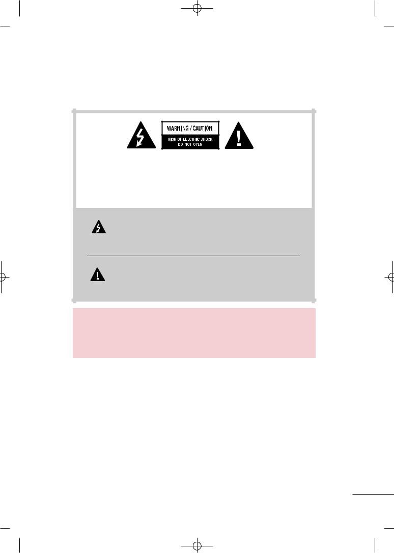
2Clean only with dry cloth.
3Do not block any ventilation openings. Install in accordance with the manufacturer’s instructions.
4Do not install near any heat sources such as radiators, heat registers, stoves, or other apparatus
(including amplifiers)that produce heat.
5
not to install TV by the hanging power and signal cables on the back of the TV.
6Do not defeat the safety purpose of the polarized or grounding-type plug. A polarized plug has
two blades with one wider than the other. A grounding type plug has two blades and a third grounding prong, The wide blade or the third prong are provided for your safety. If the provided
an outlet.
7Protect the power cord from being walked on or pinched particularly at plugs, convenience
receptacles, and the point where they exit from the apparatus.
8Only use attachments/accessories specified by the manufacturer.
9Unplug this apparatus during lightning storms or when unused for long periods of time.
2
MFL41469209-Edit1-en 7/29/08 3:52 PM Page 3
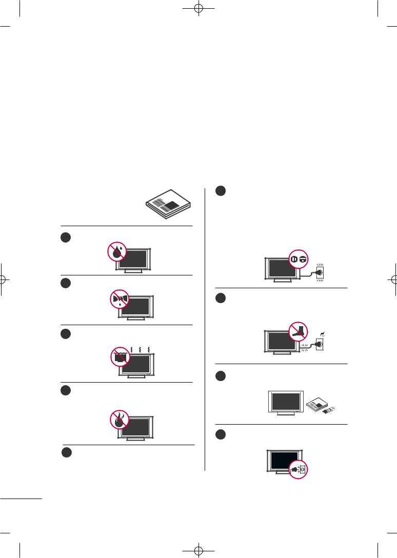
10
with the apparatus. When a cart is used, use caution when moving the cart/apparatus combination to avoid injury from tip-over.
11 |
Never touch this apparatus or antenna during |
|
a thunder or lighting storm. |
|
|
12 |
Do not allow a impact shock or any objects to |
fall into the product, and do not drop onto the screen with something.
Refer all servicing to qualified service personnel. Servicing is required when the apparatus has been damaged in any way, such as power-supply cord or plug is damaged, liquid has been spilled or objects have fallen into the apparatus, the apparatus has exposed to rain or moisture, does not operate normally, or has been dropped.
14 CAUTION concerning the Power Cord :
Most appliances recommend they be placed upon a dedicated circuit; that is, a single outlet circuit which powers only that appliance and has no additional outlets or branch circuits. Check the specification page of this owner's manual to be certain.
Do not overload wall outlets. Overloaded wall outlets, loose or damaged wall outlets, extension cords, frayed power cords, or damaged or cracked wire insulation are dangerous. Any of these conditions could result in electric shock or fire. Periodically examine the cord of your appliance, and if its appearance indicates damage or deterioration, unplug it, discontinue use of the appliance, and have the cord replaced with an exact replacement part by an authorized servicer. Protect the power cord from physical or mechanical abuse, such as being twisted,
door, or walked to plugs, wall outlets, and the point where the cord exits the
appliance.
15 Outdoor use marking :
WARNING - To reduce the risk of fire or electric shock, do not expose this appliance to rain or moisture.
16 Wet Location Marking : Apparatus shall not be exposed to dripping or splashing and no objects filled with liquids, such as vases, shall be placed on or over apparatus.
|
|
|
|
|
|
|
|
|
|
|
|
|
|
|
|
|
|
|
|
|
|
|
|
|
|
|
17 |
GROUNDING |
||||||||||
|
|
|
|
Ensure that you connect the earth ground wire |
||||||||
|
|
|
|
to prevent possible electric shock. If grounding |
||||||||
|
|
|
|
methods are not possible, have a qualified |
||||||||
|
|
|
|
electrician install a separate circuit breaker. |
||||||||
|
|
|
|
Do not try to ground the unit by connecting it |
||||||||
|
|
|
|
to telephone wires, lightening rods, or gas pipes. |
||||||||
|
|
|
|
|
|
|
|
|
|
|
|
Power |
|
|
|
|
|
|
|
|
|
|
|
|
|
|
|
|
|
|
|
|
|
|
|
|
|
Supply |
|
|
|
|
|
|
Short-circuit |
|
|
||||
|
|
|
|
|
|
|
|
Breaker |
|
|||
|
|
|
|
|
||||||||
|
|
|
|
DISCONNECTING DEVICE FROM MAINS |
||||||||
|
|
|
|
Mains plug is the disconnecting device. The |
||||||||
|
|
|
|
plug must remain readily operable. |
||||||||
|
|
|
|
|
|
|
|
|||||
|
19 |
|
|
|
|
|
direct sunlight. |
|||||
|
|
|
|
- The product can be damaged. |
||||||||
|
|
|
|
|
|
|
|
|
|
|
|
|
3
MFL41469209-Edit1-en 7/29/08 3:52 PM Page 4
CONTENTS
WARNING/CAUTION . . . . . . . . . . . . . . . . . . . . . . . . . . . . . . . 1
SAFETY INSTRUCTIONS . . . . . . . . . . . . . . . . . . . . . . . . . . 2
PREPARATION |
|
Accessories . . . . . . . . . . . . . . . . . . . . . . . . . . . . . . . . . . . . . . . . . . . . . . . . . . . . . |
. 7 |
Front Panel Information . . . . . . . . . . . . . . . . . . . . . . . . . . . . . . . . . . . |
. . 8 |
Back Panel Information . . . . . . . . . . . . . . . . . . . . . . . . . . . . . . . . . . . . |
10 |
Stand Installation . . . . . . . . . . . . . . . . . . . . . . . . . . . . . . . . . . . . . . . . . . . . |
13 |
Cable Management . . . . . . . . . . . . . . . . . . . . . . . . . . . . . . . . . . . . . . . . . |
15 |
Securing the TV to the wall fall over. . . . . . . . . . . . . . . . . . |
18 |
Protection Cover . . . . . . . . . . . . . . . . . . . . . . . . . . . . . . . . . . . . . . . . . . . . . |
19 |
Swivel Stand . . . . . . . . . . . . . . . . . . . . . . . . . . . . . . . . . . . . . . . . . . . . . . . . . . . . |
19 |
Desktop Pedestal Installation . . . . . . . . . . . . . . . . . . . . . . . . . . . |
20 |
Wall Mount: Horizontal Installation . . . . . . . . . . . . . . . . . . . |
20 |
Attaching The TV To a Desk . . . . . . . . . . . . . . . . . . . . . . . . . . . . |
20 |
Antenna Connection . . . . . . . . . . . . . . . . . . . . . . . . . . . . . . . . . . . . . . . . |
21 |
EXTERNAL EQUIPMENT SETUP
HD Receiver Setup . . . . . . . . . . . . . . . . . . . . . . . . . . . . . . . . . . . . . . . . . 22
DVD Setup . . . . . . . . . . . . . . . . . . . . . . . . . . . . . . . . . . . . . . . . . . . . . . . . . . . . . 25
VCR Setup . . . . . . . . . . . . . . . . . . . . . . . . . . . . . . . . . . . . . . . . . . . . . . . . . . . . . 28
Other A/V Source Setup . . . . . . . . . . . . . . . . . . . . . . . . . . . . . . . . . 31
PC Setup . . . . . . . . . . . . . . . . . . . . . . . . . . . . . . . . . . . . . . . . . . . . . . . . . . . . . . . . 32
USB In Setup . . . . . . . . . . . . . . . . . . . . . . . . . . . . . . . . . . . . . . . . . . . . . . . . . . 38
External Stereo Setup . . . . . . . . . . . . . . . . . . . . . . . . . . . . . . . . . . . . . . 39
AV Out Setup . . . . . . . . . . . . . . . . . . . . . . . . . . . . . . . . . . . . . . . . . . . . . . . . . 39
WATCHING TV / CHANNEL CONTROL
Remote Control Key Functions . . . . . . . . . . . . . . . . . . . . . . . . . 40
Turning On TV . . . . . . . . . . . . . . . . . . . . . . . . . . . . . . . . . . . . . . . . . . . . . . . . 42
Channel Selection . . . . . . . . . . . . . . . . . . . . . . . . . . . . . . . . . . . . . . . . . . . 42
Volume Adjustment . . . . . . . . . . . . . . . . . . . . . . . . . . . . . . . . . . . . . . . . . 42
Quick Menu . . . . . . . . . . . . . . . . . . . . . . . . . . . . . . . . . . . . . . . . . . . . . . . . . . . . 43
On-Screen Menus Selection . . . . . . . . . . . . . . . . . . . . . . . . . . . . 44
Channel Search . . . . . . . . . . . . . . . . . . . . . . . . . . . . . . . . . . . . . . . . . . . . . . . 45
- Auto Turning . . . . . . . . . . . . . . . . . . . . . . . . . . . . . . . . . . . . . . . . . . . . 45
- Manual Turning:Adding / Deleting Channels . . . . 46
Fine Tuning Adjustment . . . . . . . . . . . . . . . . . . . . . . . . . . . . . . . . . . . 47
Booster . . . . . . . . . . . . . . . . . . . . . . . . . . . . . . . . . . . . . . . . . . . . . . . . . . . . . . . . . . 48
Favorite Channels Setup . . . . . . . . . . . . . . . . . . . . . . . . . . . . . . . . . . 49
Key Lock . . . . . . . . . . . . . . . . . . . . . . . . . . . . . . . . . . . . . . . . . . . . . . . . . . . . . . . . . 50
AV Mode . . . . . . . . . . . . . . . . . . . . . . . . . . . . . . . . . . . . . . . . . . . . . . . . . . . . . . . . 51
SimpLink . . . . . . . . . . . . . . . . . . . . . . . . . . . . . . . . . . . . . . . . . . . . . . . . . . . . . . . . . 52
USB |
|
To use the USB device.................................................................................... |
54 |
Photo list................................................................................................................................. |
55 |
Music list................................................................................................................................. |
57 |
Movie List............................................................................................................................... |
59 |
Divx Registration Code................................................................................... |
60 |
PICTURE CONTROL
Watching PIP(Picture-In-Picture) . . . . . . . . . . . . . . . . . . . . . . 61
Picture Size (Aspect Ratio) Control . . . . . . . . . . . . . . . . . . 62
Preset Picture Settings . . . . . . . . . . . . . . . . . . . . . . . . . . . . . . . . . . . . . 63
- Picture ModePreset . . . . . . . . . . . . . . . . . . . . . . . . . . . . . . . . 63
- Auto Color Tone Control(Warm/Medium/Cool) . . 64
Manual Picture Adjustment . . . . . . . . . . . . . . . . . . . . . . . . . . . . . . 65
- Picture ModeUser Mode . . . . . . . . . . . . . . . . . . . . . . . . . 65
- Color Tone - User Mode . . . . . . . . . . . . . . . . . . . . . . . . . . . 66
XD - Picture Improvement Technology . . . . . . . . . . . . . 67
Advanced - Gamma . . . . . . . . . . . . . . . . . . . . . . . . . . . . . . . . . . . . . . . . . 69
Advanced - Film Mode . . . . . . . . . . . . . . . . . . . . . . . . . . . . . . . . . . . . . 70
Advanced - Black (Darkness) Level . . . . . . . . . . . . . . . . . . . 71
Advanced - Eye Care . . . . . . . . . . . . . . . . . . . . . . . . . . . . . . . . . . . . . . . 72
Picture Reset . . . . . . . . . . . . . . . . . . . . . . . . . . . . . . . . . . . . . . . . . . . . . . . . . 73
Power Indicator . . . . . . . . . . . . . . . . . . . . . . . . . . . . . . . . . . . . . . . . . . . . . . 74
Image Sticking Minimization (ISM) Method . . . . . . . 75
Power Saving Picture Mode . . . . . . . . . . . . . . . . . . . . . . . . . . . . . . 76
Factory Reset . . . . . . . . . . . . . . . . . . . . . . . . . . . . . . . . . . . . . . . . . . . . . . . . . . 77
4
MFL41469209-Edit1-en 7/29/08 3:52 PM Page 5
SOUND & LANGUAGE CONTROL
Auto Volume Leveler . . . . . . . . . . . . . . . . . . . . . . . . . . . . . . . . . . . . . . . . 78
Preset Sound Setting - Sound Mode . . . . . . . . . . . . . . . . 79
Sound Setting Adjustment - User Mode . . . . . . . . . . . 80
Balance . . . . . . . . . . . . . . . . . . . . . . . . . . . . . . . . . . . . . . . . . . . . . . . . . . . . . . . . . . . 81
TV Speakers On/Off Setup . . . . . . . . . . . . . . . . . . . . . . . . . . . . . . 82
Selecting Audio Out . . . . . . . . . . . . . . . . . . . . . . . . . . . . . . . . . . . . . . . . 83
On-Screen Menus Language Selection . . . . . . . . . . . . . . 83
Closed Caption . . . . . . . . . . . . . . . . . . . . . . . . . . . . . . . . . . . . . . . . . . . . . . . 84
TIME SETTING
Clock Setup . . . . . . . . . . . . . . . . . . . . . . . . . . . . . . . . . . . . . . . . . . . . . . . . . . . 85
Auto On/Off Time Setting . . . . . . . . . . . . . . . . . . . . . . . . . . . . . . 86
Sleep Timer Setting . . . . . . . . . . . . . . . . . . . . . . . . . . . . . . . . . . . . . . . . . 87
Auto Shut-off Setting . . . . . . . . . . . . . . . . . . . . . . . . . . . . . . . . . . . . . . . 88
APPENDIX
Troubleshooting . . . . . . . . . . . . . . . . . . . . . . . . . . . . . . . . . . . . . . . . . . . . . . 89
Maintenance . . . . . . . . . . . . . . . . . . . . . . . . . . . . . . . . . . . . . . . . . . . . . . . . . . . 90
Product Specifications . . . . . . . . . . . . . . . . . . . . . . . . . . . . . . . . . . . . . 91
Programming the Remote Control . . . . . . . . . . . . . . . . . . . 93
IR Codes . . . . . . . . . . . . . . . . . . . . . . . . . . . . . . . . . . . . . . . . . . . . . . . . . . . . . . .95
External Control Through RS-232C . . . . . . . . . . . . . . . . . .97
5
MFL41469209-Edit1-en 7/29/08 3:52 PM Page 6
PREPARATION
PREPARATION
FOR LCD TV
If the TV feels cold to the touch, there may be a small “flicker” when it is turned on. This is normal, there is nothing wrong with TV.
Some minute dot defects may be visible on the screen, appearing as tiny red, green, or blue spots. However, they have no adverse effect on the monitor's performance.
Avoid touching the LCD screen or holding your finger(s) against it for long periods of time. Doing so may produce some temporary distortion effects on the screen.
On Disposal (Only, Hg.lamp used LCD TV)
a.The fluorescent lamp used in this product contains a small amount of mercury.
b.Do not dispose of this product with general household waste.
c.Disposal of this product must be carried out in accordance to the regulations of your local authority.
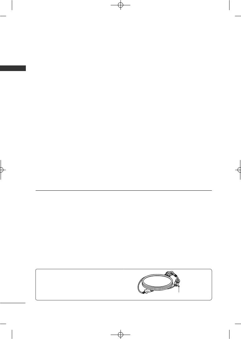
Use of ferrite core (This feature is not available for all models.)
Ferrite core can be used to reduce the electromagnetic wave when connecting the power cord.
The closer the location of the ferrite core to the power plug, the better it is.
Install the |
plug closely. |
6
MFL41469209-Edit1-en 7/29/08 3:52 PM Page 7
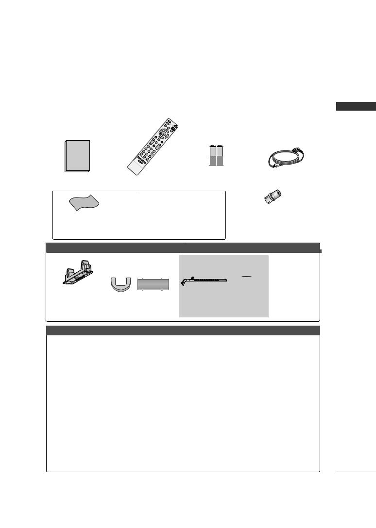
ACCESSORIES
Ensure that the following accessories are included with your TV. If an accessory is missing, please contact the dealer where you purchased the TV.
The accessories included may differ from the images below.
Owner's Manual
PIP
V
OL
1 |
MUTE |
|
42
7 |
5 |
3 |
86
09
Q.VIEW
RETURN
FAV CH
TV |
|
|
P |
|
|
STB |
O |
|
Q.M |
WE |
|
ENU |
R |
IN |
ME |
|
P |
NU |
D |
UT |
|
VD |
|
ENTER
AV
MODE
1.5V |
1.5V |
PREPARATION
Owner’s Manual |
Remote Control |
Batteries |
Power Cord |
|
|
For Plasma TV models
|
|
|
(Only 50PG60**, |
|
|
(Only 42PG60**) |
|
|
|
|
|
|
|
|
|
|
|
|
|
|
50/60PG70** ) |
|
|
|
|
|
|
|
|
|
|
|
x 4 |
|
|
Protection cover |
|
|
|
|
|
|
Ferrite Core |
|
(Refer to p.19) |
|
|
|
|
|
Bolts for stand |
|
|
|
|
|
Cable Holder |
|
(This feature is not |
|||
(This accessories can be different Cable Management Clip |
assembly |
|
||||||
|
|
available for all models.) |
||||||
from the figures shown here |
|
|
|
|
(Refer to P.13) |
|||
depending on your models.) |
|
|
|
|
|
|
||
|
|
|
|
|
|
|
||
For LCD TV models |
|
|
|
|
|
|
|
|
32/42/47LG60* * |
|
|
|
|
|
|
|
|
|
|
|
|
(Only 32LG60**) |
(Only 42LG60**) |
|||
|
|
|
or |
|
|
|
|
|
|
|
|
|
x 3 |
x 4 |
x 2 |
x 4 |
x 1 |
Cable |
|
Protection cover |
|
|
|
|
|
|
|
(Refer to p.19) |
|
|
|
|
|
||
Management |
|
|
|
|
|
|
||
|
(This accessories can be |
|
|
|
|
|
||
Clip |
|
|
Bolts for stand assembly |
|
|
|||
different from the figures shown here |
|
|
|
|||||
|
|
(Refer to P.14) |
|
|
||||
|
|
depending on your models.) |
|
|
|
|||
32LG70* * |
|
|
|
|
|
|
|
|
x 4 |
|
x 4 |
Protection cover |
|
|
|
|
|
|
|
|
|
|
|
|
||
Bolts for stand assembly |
(Refer to p.19) |
|
Screw for stand fixing |
|||||
(This accessories can be different |
|
|||||||
(Refer to P.14) |
|
from the figures shown here depend- |
|
(Refer to P20) |
|
|||
ing on your models.)
7
MFL41469209-Edit1-en 7/29/08 3:52 PM Page 8
PREPARATION
FRONT PANEL INFORMATION
PREPARATION
■Image shown may differ from your TV.
■NOTE: If your TV has a protection tape attached, remove the tape.
And then wipe the TV with a cloth (If a polishing cloth is included with your TV, use it).
Plasma TV Models
Remote Control Sensor |
POWER Button |
Power/Standby Indicator
Illuminates red in standby mode.
Illuminates green when the set is switched on.
INPUT |
MENU |
ENTER |
VOL |
CH |
INPUT |
MENU |
ENTER |
VOLUME (-,+) |
CHANNEL ( |
E D |
|
|
|
|
, |
) |
||
Button |
Button |
Button |
Buttons |
Buttons |
|
|
8
MFL41469209-Edit1-en 7/29/08 3:52 PM Page 9
LCD TV Models
32/42/47LG60**
|
CH |
CHANNEL ( |
, |
) |
|
|
|||
|
|
Buttons |
|
|
Intelligent Sensor |
|
VOLUME (+, -) |
|
|
Adjusts picture according |
VOL |
|
||
|
|
|
||
the surrounding conditions |
|
Buttons |
|
|
|
|
|
|
|
POWER
Remote Control Sensor
Power/Standby Indicator
•Illuminates red in standby mode.
•Illuminates White when the TV is
|
switched on. |
Note: You |
adjust Power |
Indicator in |
Option menu. |
ENTER Button
ENTER
MENU Button
MENU
INPUT Button
INPUT
32LG70**
|
CH |
CHANNEL ( , ) |
|
|
|
||
|
|
Buttons |
|
Intelligent Sensor |
VOL |
VOLUME (+, -) |
|
Adjusts picture according to the surrounding |
Buttons |
||
|
|||
conditions |
|
|
|
Power/Standby |
ENTER |
|
|
Illuminates red in |
|
ENTER Button |
|
|
|
||
blue |
MENU |
|
|
(Can be adjusted |
MENU Button |
||
|
|||
the Option menu.) |
|
|
|
Remote Control Sensor |
INPUT |
INPUT Button |
|
|
POWER Button
PREPARATION
9

MFL41469209-Edit1-en 7/29/08 3:52 PM Page 10
PREPARATION
PREPARATION
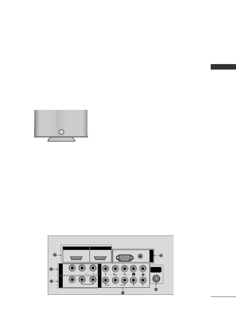
BACK PANEL INFORMATION
■ Here shown may be somewhat different from your TV.
Plasma TV Models
|
|
|
|
|
|
11 |
|
|
|
|
3 |
|
|
|
|
|
|
|
|
1 |
8 |
|
|
|
-VIDEO |
|
10 |
|
|
|
|
S |
|
|
|
|
|
|
|
|
9 |
42/50PG60** |
|
|
|
2 |
|
|
|
|
|
|
|
|
|
|
|
|
|
RS-232C IN |
|
|
|
|
|
|
(CONTROL ) |
|
|
|
|
|
|
|
|
7 |
|
HDMI/DVI IN |
HDMI IN |
|
|
|
|
|
|
|
RGB(PC) |
AUDIO |
IN |
|
1 |
|
|
|
(RGB/DVI) |
RGB |
6 |
|
|
|
|
|||
|
|
|
|
|
||
|
|
|
|
|
|
|
2 |
IN 1 |
|
|
|
|
|
VIDEO |
(MONO) AUDIO |
2 |
|
|
|
|
AV |
AUDIO |
|
|
|||
VIDEO |
|
|
||||
|
|
|
|
|||
3 |
OUT |
|
1 |
|
|
|
|
|
|
|
|
||
|
|
|
|
|
|
|
|
|
VARIABLE AUDIO OUT |
COMPONENT IN |
|
ANTENNA |
|
|
|
|
|
|
|
IN |
|
|
|
4 |
|
|
5 |
|
|
|
|
|
|
|
50/60PG70** |
|
|
|
|
|
|
HDMI/DVI IN
1
VIDEO |
VIDEO |
|
MONO |
OUT |
L |
AUDIO |
VARIABLEAUDIO |
|
L/ |
|
|
AV 1 AV OUT
23
HDMI IN
|
AUDIO |
|
6 |
RS-232C IN |
IN (PC) |
(CONTROL ) |
7 |
2 
1 
VIDEO |
AUDIO |
ANTENNA |
|
COMPONENT IN |
|||
IN |
|||
|
4 |
5 |
|
|
|
||
10
MFL41469209-Edit1-en 7/29/08 3:52 PM Page 11
32LG60** 42/47LG60**
LCD TV Models
11
32/42/47LG60** |
3 |
1
10
9
AV IN 2 |
AV IN 2 |
8
32LG70**
11
10
9
8
AV IN 2
|
HDMI/DVI IN |
|
HDMI IN |
|
|
|
|
||
|
1 |
1 |
|
|
2 |
RGB (PC) |
AUDIO |
IN |
|
|
|
|
|
|
|
|
RGB |
6 |
|
|
|
|
|
|
|
|
(RGB/DVI) |
|
|
|
|
|
|
|
|
|
|
|
|
|
IN 1 |
|
|
|
IN |
|
2 |
ANTENNA |
|
2 |
|
|
|
COMPONENT |
|
||||
|
|
|
|
|
|
|
IN |
||
|
VIDEO |
L/MONO |
AUDIO |
R |
|
|
|
||
|
|
|
|
|
|||||
|
AV |
|
|
|
|
1 |
|
|
|
3 |
OUT |
|
|
|
|
|
|
||
|
|
|
|
|
|
|
|
||
|
|
VARIABLE AUDIO OUT |
VIDEO |
AUDIO |
|
|
|||
|
|
|
|
|
|
|
|
|
5 |
|
|
|
|
|
|
4 |
|
|
|
PREPARATION
11
MFL41469209-Edit1-en 7/29/08 3:52 PM Page 12
PREPARATION
PREPARATION
1
Connect a HDMI (DVI) connection to either input.
2AV (Audio/Video) IN 1
Connect audio/video output from an external device to these jacks.
3AV OUT
Connect a second TV or monitor.
VARIABLE AUDIO OUT
Connect an external amplifier or add a subwoofer to your surround sound system.
4COMPONENT IN
Connect a component video/audio device to these jacks.
5ANTENNA IN
Connect over-the air signals to this jack.
6
RGB(PC)
Connect the output from a PC.
AUDIO(RGB/DVI)
Connect the audio from a PC or DTV.
7RS-232C IN (CONTROL)(Only Plasma TV models)
For external control devices.
8Power Cord Socket
For operation with AC power.
Caution: Never attempt to operate the TV on DC power.
9AV (Audio/Video) IN 2
Connect audio/video output from an external device to these jacks.
10S-VIDEO
Connect S-Video out from an S-VIDEO device.
11 USB IN
12
MFL41469209-Edit1-en 7/29/08 3:52 PM Page 13
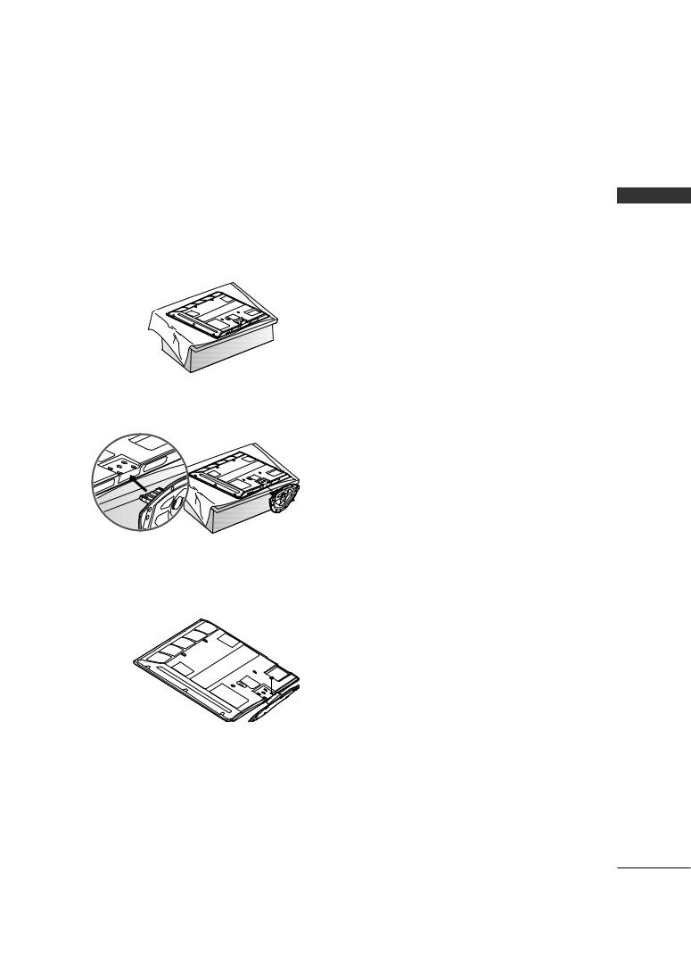
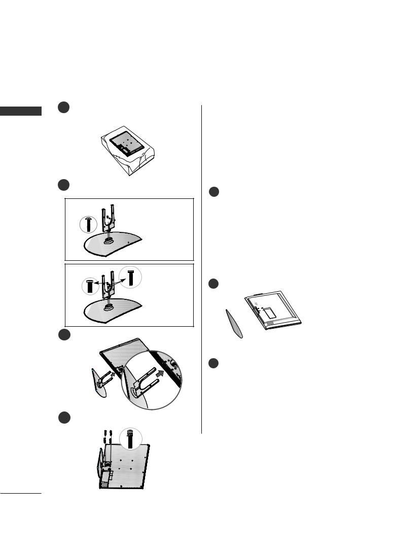
STAND INSTALLATION
■ Image shown may differ from your TV
Plasma TV Models
42PG60**
1 the TV screen side down on a to protect the screen from
damage.
2Assemble the TV as shown.
3Fix the 4 bolts securely using the holes in the back of the TV.
50/60PG70**
1 side down on a the screen from
damage.
2Assemble the parts of the Stand Body with the Cover Base of the TV.
 STAND BODY
 COVER BASE
3Assemble the TV as
4
PREPARATION
! NOTE
G When assembling the desk type stand, check whether the bolt is fully tightened. (If not tightened fully, the product can tilt forward after the product installation). If you tighten the bolt with excessive force, the bolt can deviate from abrasion of the tightening part of the bolt.
13
MFL41469209-Edit1-en 7/29/08 3:52 PM Page 14
PREPARATION
LCD TV Models
32/42LG60**
1Carefully place the TV screen side down on a cushioned surface to protect the screen from
PREPARATION |
damage. |
|
32LG70**
1place the TV screen side down on a
surface to |
screen from |
damage.
2 |
Assemble the parts of the Stand Body with |
2 |
|
the Cover Base of the TV. |
32LG60**


 STAND BODY
 COVER BASE
42LG60**
3
 STAND BODY
 COVER BASE
3Assemble the TV
4
4 |
Fix the 4 bolts |
the holes in the |
back of the TV. |
|
BODY
D BODY
ER BASE
holes in the
! NOTE
G When assembling the desk type stand, check whether the bolt is fully tightened. (If not tightened fully, the product can tilt forward after the product installation). If you tighten the bolt with excessive force, the bolt can deviate from abrasion of the tightening part of the bolt.
14
MFL41469209-Edit1-en 7/29/08 3:52 PM Page 15
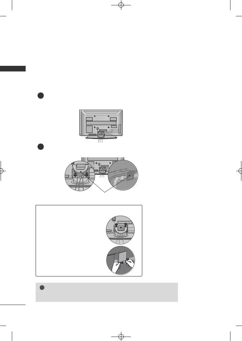
CABLE MANAGEMENT
■ Here shown may be somewhat different from your TV.
Plasma TV Models
42PG60**
1
2
If your TV has CABLE HOLDER, fix it as shown and bundle the cables.
CABLE HOLDER
CLIP
How to remove the
CABLE MANAGEMENT CLIP
G First, press the cable management. Hold the CABLE MANAGEMENT CLIP with both hands and pull it upward.
! NOTE
G Do not hold the CABLE MANAGEMENT CLIP when moving the TV.
- If the TV is dropped, you may be injured or the product may be broken.
PREPARATION
15
MFL41469209-Edit1-en 7/29/08 3:52 PM Page 16
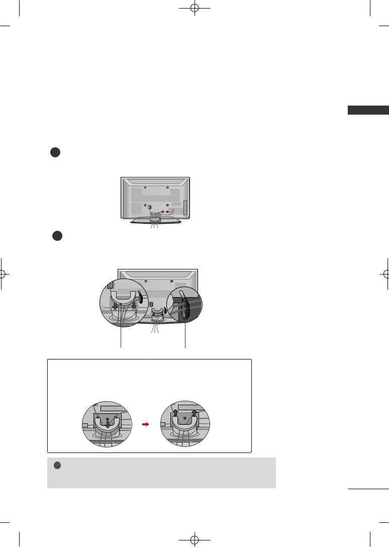
PREPARATION
Plasma TV Models
PREPARATION |
50PG60**, 50/60PG70** |
|
|
|
1 |
|
tion. |
EQUIPMENT SETUP sec-
2Install the CABLE MANAGEMENT CLIP as shown.
CABLE MANAGEMENT CLIP
How to remove the
CABLE MANAGEMENT CLIP
G Hold the CABLE MANAGEMENT CLIP with both hands and pull it upward.
G Separate CABLE MANAGEMENT CLIP from TV by pressing two latches.
! NOTE
G Do not hold the CABLE MANAGEMENT CLIP when moving the TV.
- If the TV is dropped, you may be injured or the product may be broken.
16
MFL41469209-Edit1-en 7/29/08 3:52 PM Page 17
LCD TV Models
32/42LG60**
1 |
BLE |
|
Turn the CABLE MANAGEMENT CLIP as
shown.
Note: This cable management clip can be broken by excessive pressure.
2Connect the cables as To connect additional
EXTERNAL EQUIPMENT
32LG70**
1Connect the cables as necessary.
To connect additional equipment, see the
EXTERNAL EQUIPMENT SETUP section.
Install the CABLE MANAGEMENT CLIP as shown.
|
CABLE MANAGEMENT CLIP |
3 |
CABLE MANAGEMENT |
PREPARATION
17
MFL41469209-Edit1-en 7/29/08 3:52 PM Page 18
PREPARATION
|
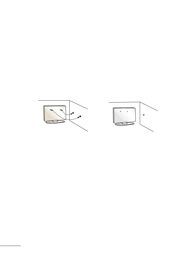
SECURING THE TV TO THE WALL FALL OVER. |
|||||||||||||||||||
|
This feature is not available for all models. |
|||||||||||||||||||
|
||||||||||||||||||||
|
Here shown may be somewhat different from your TV. |
|||||||||||||||||||
PREPARATION |
||||||||||||||||||||
This will also prevent the TV from damage. Ensure that children do not climb or hang from the TV. |
||||||||||||||||||||
|
■ Position the TV close to the wall to avoid the possibility of it falling when pushed. |
|||||||||||||||||||
|
■ The instructions shown below are a safer way to set up the TV, which is to fix it to the wall, avoiding the |
|||||||||||||||||||
|
possibility of it falling forwards if pulled. This will prevent the TV from falling forward and causing injury. |
|||||||||||||||||||
|
■ You should purchase necessary components to prevent TV from falling off of the stand. |
|||||||||||||||||||
|
|
|
|
|
|
|
|
|
|
|
|
|
|
|
|
|
|
|
|
|
|
|
|
|
|
|
|
|
|
|
|
|
|
|
|
|
|
|
|
|
|
|
|
|
|
|
|
|
|
|
|
|
|
|
|
|
|
|
|
|
|
|
|
|
|
|
|
|
|
|
|
|
|
|
|
|
|
|
|
|
|
|
|
|
|
|
|
|
|
|
|
|
|
|
|
|
|
|
|
|
|
|
|
|
|
|
|
|
|
|
|
|
|
|
|
|
|
|
|
|
|
|
|
|
|
|
|
|
|
|
|
|
|
|
|
|
|
|
|
|
|
|
|
|
|
|
|
|
|
|
|
|
|
|
|
|
|
|
|
|
|
|
|
|
|
|
|
|
|
|
|
|
|
|
|
|
|
|
|
|
|
|
|
|
|
|
|
|
|
|
|
|
|
|
|
|
|
|
|
|
|
|
|
|
|
|
|
|
|
|
|
|
|
|
|
|
|
|
|
|
|
|
|
|
|
|
|
|
|
|
|
|
|
|
|
|
|
|
|
|
|
|
|
|
|
|
|
|
|
|
|
|
|
|
|
|
|
|
|
|
|
|
|
|
|
|
|
|
|
|
|
|
|
|
|
|
|
|
|
|
|
|
|
|
|
|
|
|
|
|
|
|
|
■Insert the eye-bolts (or TV brackets and bolts) to tighten the product to the wall as shown in the picture. *If your product has the bolts in the eye-bolts position before inserting the eye-bolts, loosen the bolts.
Secure the wall brackets with the bolts (not provided as parts of the product, must purchase separately) to the wall. Match the height of the bracket that is mounted on the wall to the holes in the product.
Ensure the eye-bolts or brackets are tightened securely.
■Use a sturdy rope (not provided as parts of the product, must purchase separately) to tie the product. It is safer to tie the rope so it becomes horizontal between the wall and the product.
! NOTE
GWhen moving the TV undo the cords first.
GUse a platform or cabinet strong and large enough to support the size and weight of the TV.
GTo use the TV safely make sure that the height of the bracket on the wall and on the TV is the same.
18
MFL41469209-Edit1-en 7/29/08 3:52 PM Page 19
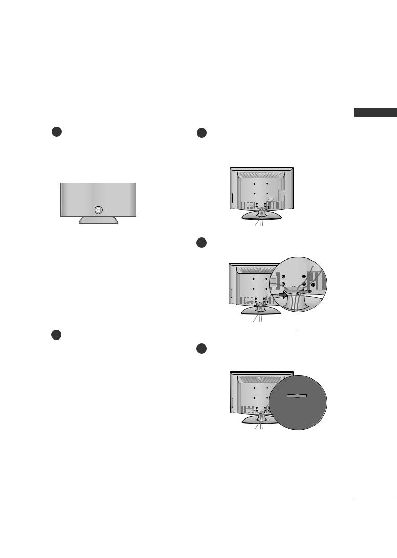
PROTECTION COVER
■ Image shown may differ from your TV.
After removing the stand, install the included protection cover over the hole for the stand.
Press the PROTECTION COVER into the TV until you hear it click.
Plasma TV Models |
LCD TV Models |
|
32LG70** |
LCD TV Models 32/42/47LG60**
PREPARATION
removing the protection from the protection adhere it to the TV as
shown.
SWIVEL STAND
After installing the TV, you can adjust the TV set manually to the left or right direction by 20 degrees to suit your viewing position.
19
MFL41469209-Edit1-en 7/29/08 3:52 PM Page 20
PREPARATION
PREPARATION
■ This part mainly use picture for Plasma TV model.
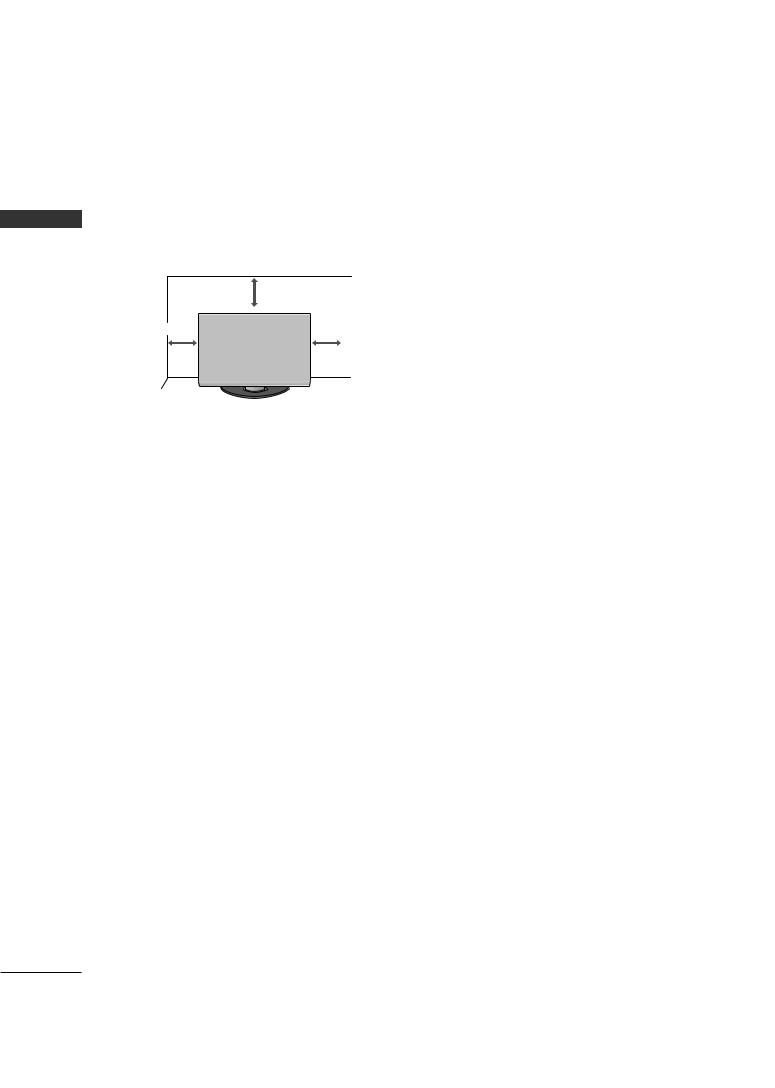
DESKTOP PEDESTAL INSTALLATION
For adequate ventilation allow a clearance of 4” (10cm) all around the TV.
|
4 inches |
|
4 inches |
4 inches |
4 inches |
|
 CAUTION G Ensure adequate ventilation by following the clearance recommendations.
G Do not mount near or above any type of heat source.
WALL MOUNT: HORIZONTAL INSTALLATION
For adequate ventilation allow a clearance of 4” (10cm) all around the TV. We recommend that you use an LG brand wall mount when mounting the TV to a wall.
4 inches
4 inches
4 inches |
4 inches |
 4 inches
ATTACHING THE TV TO A DESK (Only 32LG70**)
The TV must be attached to a desk so it cannot be pulled in a forward/backward direction, potentially causing injury or damaging the product.
Stand |
1-Screw
(provided as parts of the product)
 WARNING
G To prevent TV from falling over, the TV should be securely attached to the floor/wall per installation instructions. Tipping, shaking, or rocking the machine may cause injury.
20
MFL41469209-Edit1-en 7/29/08 3:52 PM Page 21
■ To prevent damage do not connect to the mains outlet until all connections are made between the devices.
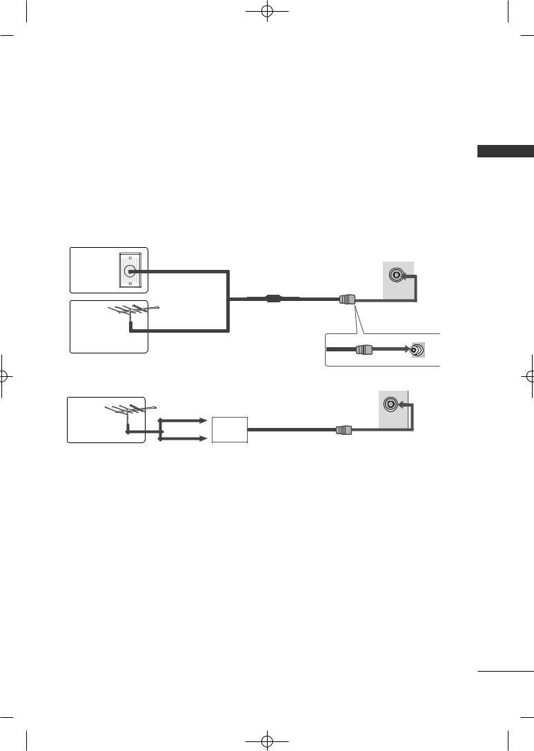
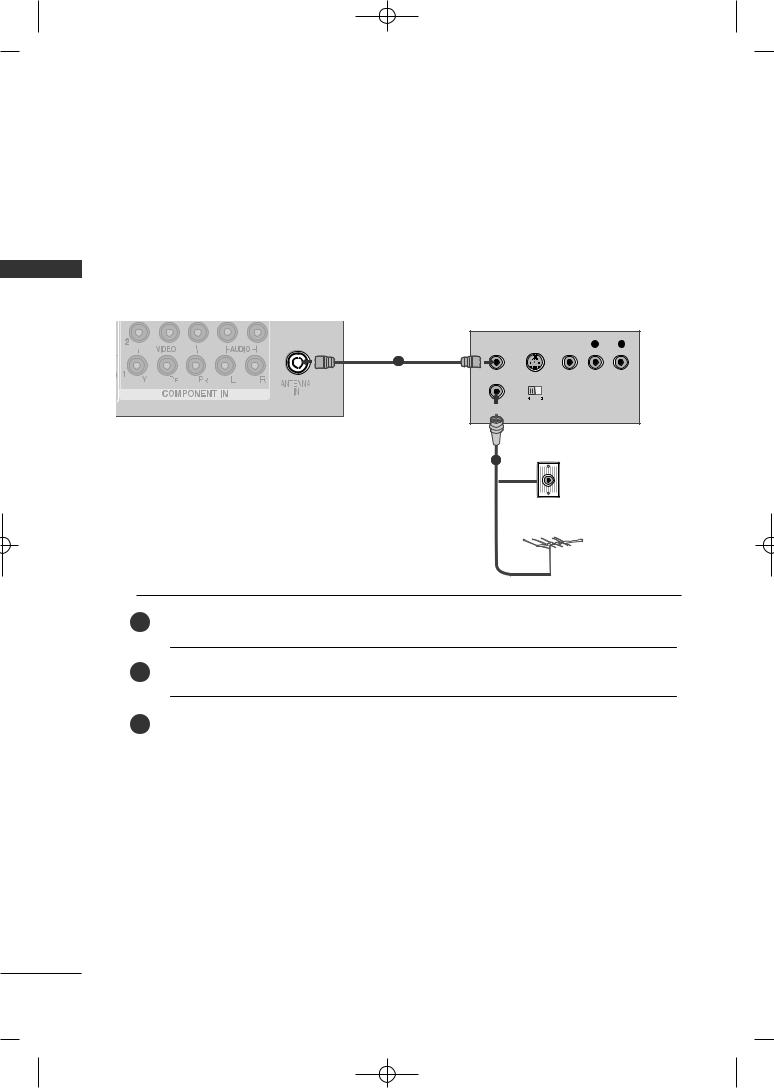
ANTENNA CONNECTION
■For optimum picture quality, adjust antenna direction.
■An antenna cable and converter are not supplied.
Wall |
Multi-family Dwellings/Apartments |
|
(Connect to wall antenna socket) |
||
Antenna |
||
|
||
Socket |
|
ANTENNA
IN
RF Coaxial Wire (75 ohm)
Outdoor
Antenna
Single-family Dwellings /Houses
(Connect to wall jack for outdoor antenna)
UHF
|
ANTENNA |
|
Antenna |
IN |
|
Signal |
||
|
||
|
Amplifier |
|
|
VHF |
■In poor signal areas, to achieve better picture quality it may be necessary to install a signal amplifier to the antenna as shown above.
■If signal needs to be split for two TVs, use an antenna signal splitter for connection.
PREPARATION
21
MFL41469209-Edit1-en 7/29/08 3:52 PM Page 22
EXTERNAL EQUIPMENT SETUP
SETUP EQUIPMENT EXTERNAL
■To avoid damaging any equipment, never plug in any power cords until you have finished connecting all equipment.
■This section on EXTERNAL EQUIPMENT SETUP mainly uses diagrams for the Plasma TV models.
■Image shown may differ from your TV.
HD RECEIVER SETUP
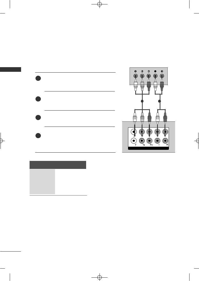
When connecting with a component cable
1Connect the video outputs (Y, PB, PR) of the digital set top box to the COMPONENT IN VIDEO jacks on the
TV.
the digital set-top box to the COMPONENT IN AUDIO jacks on the TV.
Turn on the digital set-top box.
(Refer to the owner’s manual for the digital set-top box.)
Select Component1 input source using the INPUT button on the remote control.
If connected to COMPONENT IN2, select
Component2 input source.
Signal |
Component |
480i/576i |
Yes |
480p/576p |
Yes |
720p/1080i |
Yes |
1080p |
Yes |
(Only 50Hz, 60Hz)
12
2 
 AUDIO
AUDIO 
1
COMPONENT IN
22
MFL41469209-Edit1-en 7/29/08 3:52 PM Page 23
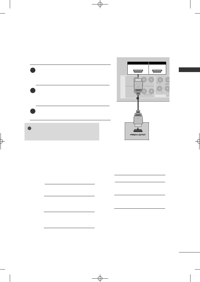
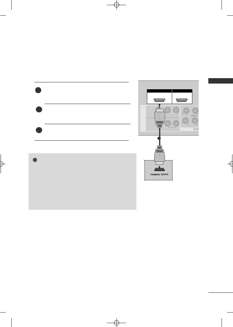
When connecting with a HDMI cable
Connect the HDMI output of the digital set-top box to the
1HDMI/DVI IN 1, HDMI IN 2 or HDMI IN 3(Except 32LG60**) jack on the TV.
the remote control.
Turn on the digital set-top box.
(Refer to the owner’s manual for the digital set-top box.)
HDMI/DVI IN |
HDMI IN |
1 |
2 |
IN 1
ONO AUDIO R
AV
OUT
VARIABLE AUDIO
1
! NOTE
G TV can receive the video and audio signal simultaneously with using a HDMI cable.
HDMI-DTV mode
Plasma TV Models
Resolution |
Horizontal |
Vertical |
|
Frequency(kHz) |
Frequency(Hz) |
||
|
|||
720x480 |
31.47 |
59.94 |
|
31.50 |
60.00 |
||
|
|||
720x576 |
31.25 |
50.00 |
|
|
44.96 |
59.94 |
|
1280x720 |
45.00 |
60.00 |
|
|
37.50 |
50.00 |
|
|
33.72 |
59.94 |
|
1920x1080i |
33.75 |
60.00 |
|
|
28.125 |
50.00 |
|
|
67.432 |
59.94 |
|
|
67.50 |
60.00 |
|
1920x1080p |
56.25 |
50.00 |
|
27.0 |
24.00 |
||
|
|||
|
33.75 |
30.00 |
|
|
|
|
LCD TV Models
Resolution |
Horizontal |
Vertical |
|
Frequency(kHz) |
Frequency(Hz) |
||
|
|||
720x480 |
31.47 |
59.94 |
|
31.50 |
60.00 |
||
|
|||
720x576 |
31.25 |
50.00 |
|
|
44.96 |
59.94 |
|
1280x720 |
45.00 |
60.00 |
|
|
37.50 |
50.00 |
|
1920x1080i |
33.72 |
59.94 |
|
33.75 |
60.00 |
||
|
28.125 |
50.00 |
|
|
67.432 |
59.94 |
|
|
67.50 |
60.00 |
|
1920x1080p |
56.25 |
50.00 |
|
27.00 |
24.00 |
||
|
|||
|
33.75 |
30.00 |
|
|
|
|
SETUP EQUIPMENT EXTERNAL
23
MFL41469209-Edit1-en 7/29/08 3:52 PM Page 24
EXTERNAL EQUIPMENT SETUP
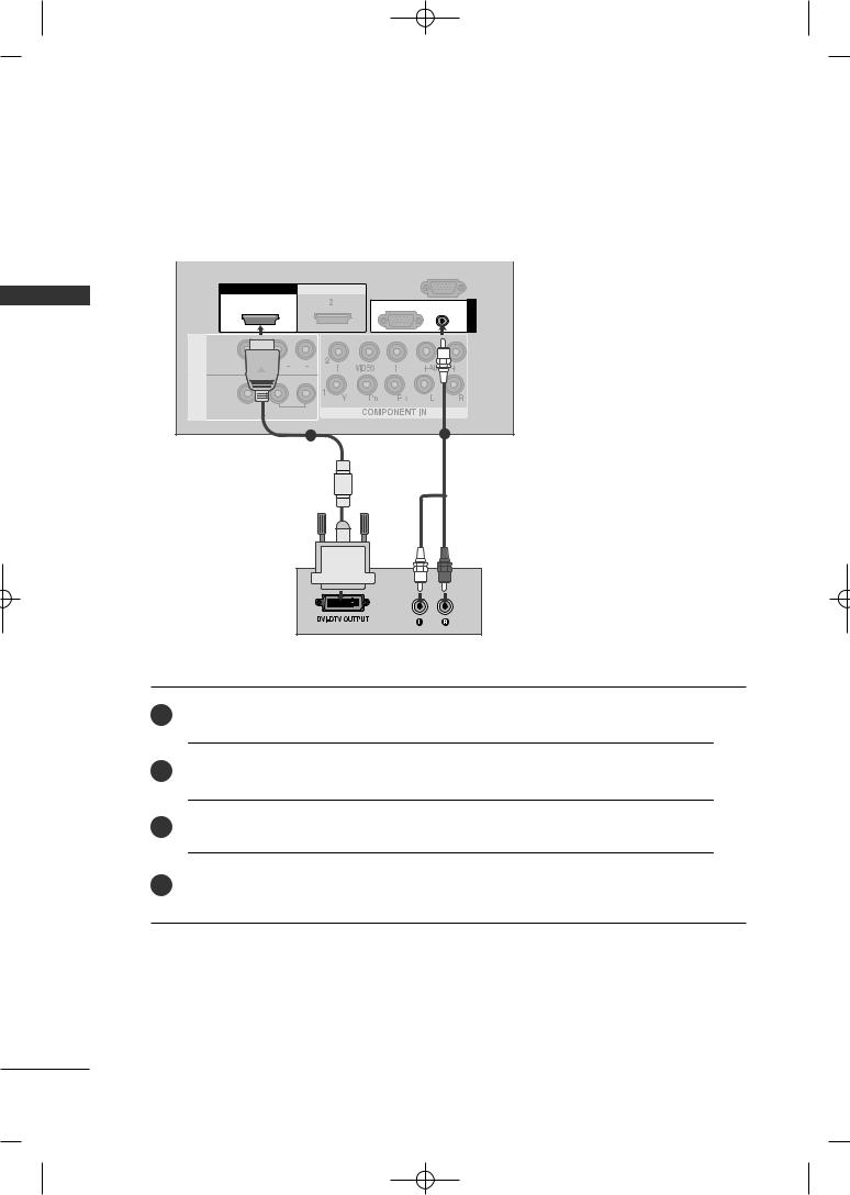
When connecting with a HDMI to DVI cable
|
|
|
|
RS-232C IN |
|
|
|
|
|
(CONTROL) |
|
|
HDMI/DVI IN |
IN |
|
|
|
|
|
1 |
RGB(PC) |
AUDIO |
IN |
EXTERNAL |
|
|
|
(RGB/DVI) |
RGB |
AV |
|
|
|
||
|
IN 1 |
|
|
|
|
SETUPEQUIPMENT |
V |
AUDIO |
|
|
|
OUT |
|
|
|
|
|
|
|
VARIABLE |
|
|
|
|
|
1 |
|
2 |
|
1Connect the DVI output of the digital set-top box to the HDMI/DVI IN 1 jack on the TV.
jack on the TV.
Turn on the digital set-top box. (Refer to the owner’s manual for the digital set-top box.)
Select HDMI1/DVI input source using the INPUT button on the remote control.
24
MFL41469209-Edit1-en 7/29/08 3:52 PM Page 25
DVD SETUP
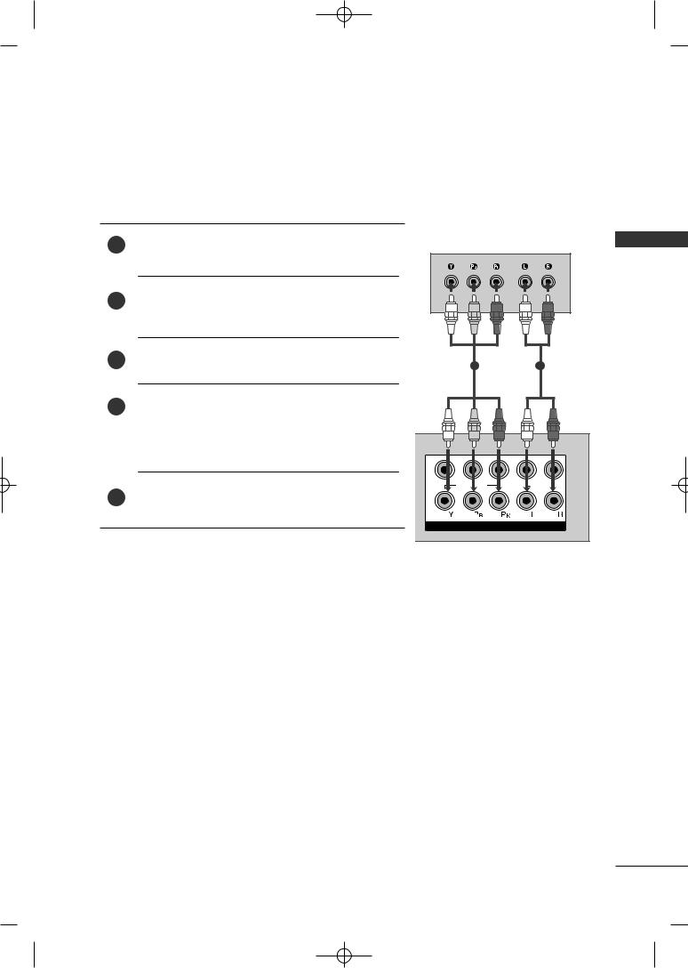
When connecting with a component cable
1 |
Connect the video outputs (Y, PB, PR) of the DVD to the |
COMPONENT IN VIDEO jacks on the TV. |
Turn on the DVD player, insert a DVD.
1 |
2 |
Select Component1 input source using the INPUT button on the remote control.
If connected to COMPONENT IN2, select Component 2 input source.
Refer to the DVD player's manual for operating instructions.
2 |
AUDIO |
1 |
COMPONENT IN |
Component Input ports
To achieve better picture quality, connect a DVD player to the component input ports as shown below.
Component ports on the TV |
Y |
PB |
PR |
|
|
|
|
|
|
|
|
|
|
|
|
|
|
|
Y |
PB |
PR |
|
|
Video output ports |
Y |
B-Y |
R-Y |
|
|
on DVD player |
Y |
Cb |
Cr |
|
|
|
Y |
Pb |
Pr |
HDMIHDMI/DVI IN |
HDMIININ |
|
1 |
2 |
|||
|
|
|
|
VIDEO L/MONO AUDIO R
SETUP EQUIPMENT EXTERNAL
25
MFL41469209-Edit1-en 7/29/08 3:52 PM Page 26
EXTERNAL EQUIPMENT SETUP
SETUP EQUIPMENT EXTERNAL
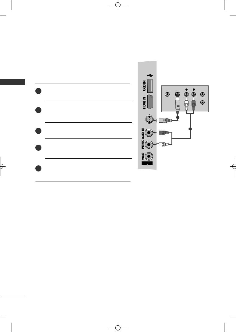
When connecting with an S-Video cable
Connect the S-VIDEO output of the DVD to the S -
1VIDEO input on the TV.
audio outputs of the DVD to the AUDIO on the TV.
Turn on the DVD player, insert a DVD.
Select AV2 input source using the INPUT button on the remote control.
Refer to the DVD player's manual for operating instructions.
3
S-VIDEO


 2
2
VIDEO |
S-VIDEO |
L |
R |
ANT IN |
|
OUTPUT |
|
|
ANT OUT |
|
SWITCH |
|
|
|
1
2
26
MFL41469209-Edit1-en 7/29/08 3:52 PM Page 27
When connecting HDMI cable |
|
|
EXTERNAL |
||
1 |
Connect the HDMI output of the DVD to the |
HDMI/DVI IN |
HDMI IN |
||
|
|||||
HDMI/DVI IN 1, HDMI IN 2 or HDMI IN 3(Except |
|
||||
|
1 |
2 |
|
||
|
32LG60**) jack on the TV. |
|
|
EQUIPMENT |
|
2 |
HDMI1/DVI, HDMI2 or HDMI3(Except |
IN 1 |
VARIABLE AUDIO |
||
|
32LG60**) input source using the INPUT button on |
L/MONO AUDIO R |
|
||
|
the remote control. |
AV |
|
|
|
|
|
OUT |
|
|
|
3 |
Refer to the DVD player's manual for operating instruc- |
|
|
SETUP |
|
|
tions. |
|
|
||
|
|
|
|
||
|
|
1 |
|
|
|
!
G TV can receive the video and audio signal simultaneously with using a HDMI cable.
G If the DVD supports Auto HDMI function, the output resolution of the source device will be automatically set to 1280x720p.
G If the DVD player does not support Auto HDMI, you need to set the DVD output resolution appropriately.
To get the best picture quality, adjust the output resolution of the source device to 1280x720p.
(42/47LG60**, 50/60PG70**: 1920X1080i/1080p)
27
MFL41469209-Edit1-en 7/29/08 3:52 PM Page 28
EXTERNAL EQUIPMENT SETUP
VCR SETUP
SETUP EQUIPMENT EXTERNAL
■To avoid picture noise (interference), allow adequate distance between the VCR and TV.
■Typically a frozen still picture from a VCR. If 4:3 picture format is used for an extended period the fixed
images on the sides of the screen may remain visible.
HDMI IN
When connecting with an antenna
ANT OUT S-VIDEO VIDEO |
L |
R |
1
ANTENNA
IN
OUTPUT
SWITCH
Wall Jack
2
Antenna
1 Connect the ANT OUT socket of the VCR to ANTENNA IN socket on the TV.
Press the PLAY button on the VCR and match |
appropriate program between the TV and VCR for |
viewing. |
|
|
|
28
 Loading...