

LG 47LF7700, 42LF7700, 37LF7700 Owner's Manual

Please read this manual carefully before operating
your TV. Retain it for future reference.
Record model number and serial number of the TV.
Refer to the label on the back cover and quote this
information to your dealer when requiring service.
LCD TV
OWNER’S MANUAL
LCD TV MODELS
32LF77
37LF77
42LF77
47LF77
ENGLISH
Trade Mark of the DVB Digital Video
Broadcasting Project (1991 to 1996)
ID Number (s):
6499 : 32LF7700
6500 : 37LF7700
6501 : 42LF7700
6502 : 47LF7700
/WNERgS
-ANUAL
Owner's manual
RW230
(32LF77**) (32/37/42/47LF77**)
AW-47LG30M
ACCESSORIES
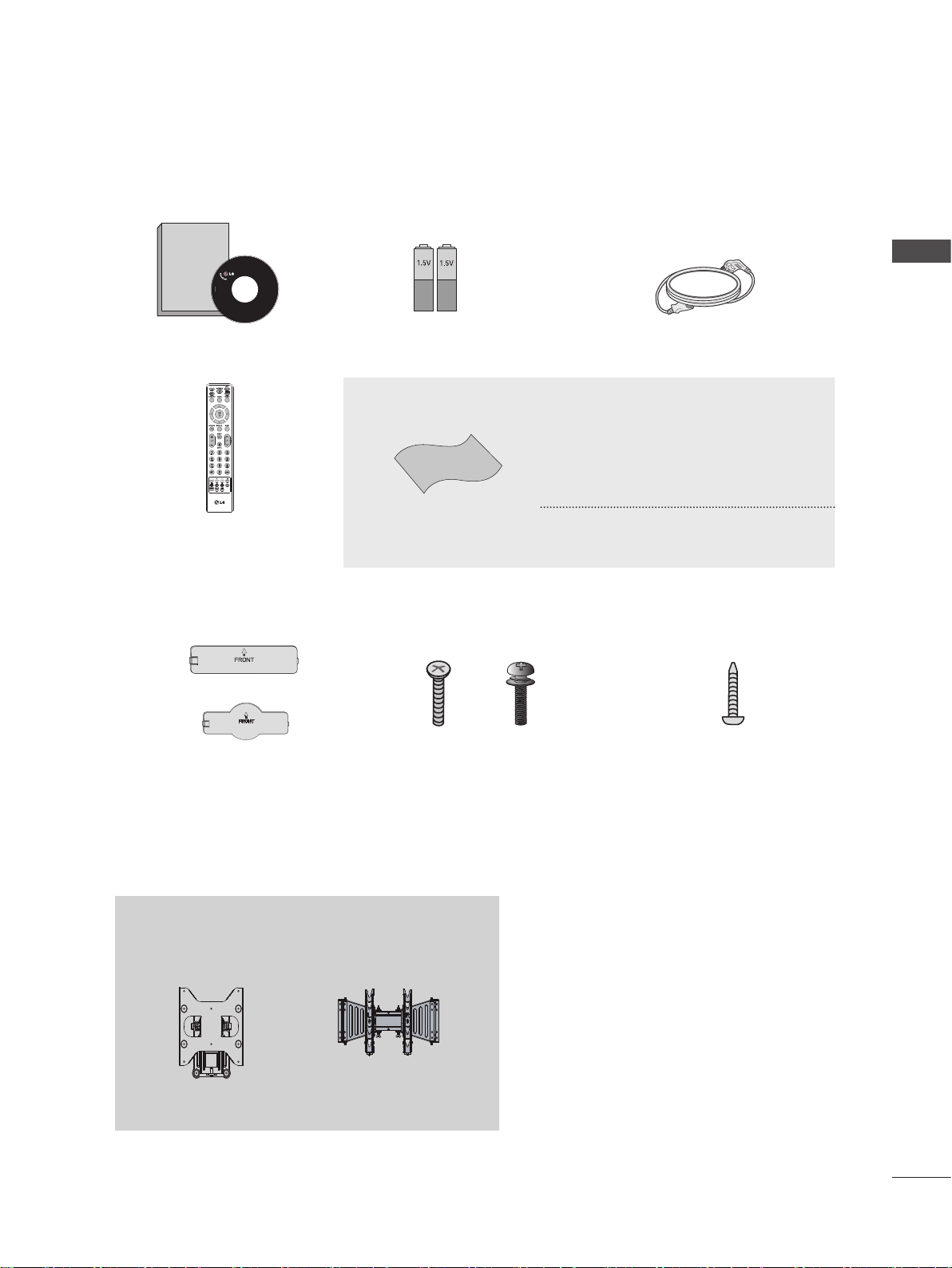
Ensure that the following accessories are included with your TV. If an accessory is missing, please contact the dealer
where you purchased the TV.
Image shown may differ from your TV
■
Owner’s Manual Batteries Power Cord
This item is not included for all models.
* Lightly wipe any stains or
ngerprints on the surface of the TV
with the polishing cloth.
ACCESSORIES
Polishing Cloth
Remote Control
or
Protection Cover
(Refer to p.10)
Wall Mounting Bracket (Seperate purchase)
Polishing cloth for use on
the screen.
(Only 32/37/42LF77**) (Only 32/37LF77**)
Bolts for stand assembly
(Refer to p.6)
Do not use excessive force. This may
cause scratching or discolouration.
x 4 x 4
1-screw for stand xing
(Refer to p.7)
GB-1

CONTENTS
ACCESSORIES
PREPARATION
Front Panel Controls - - - - - - - - - - - - - - - - - - - - - - - - 4
CONTENTS
Back Panel Information- - - - - - - - - - - - - - - - - - - - - - - 5
Stand Installation - - - - - - - - - - - - - - - - - - - - - - - - - - - 6
Desktop Pedestal Installation - - - - - - - - - - - - - - - - - - 7
Attaching the TV to a Desk (Only 32/37LF77**)- - - - - - 7
Careful installation advice - - - - - - - - - - - - - - - - - - - - - 8
Back Cover for Wire Arrangement - - - - - - - - - - - - - - - 9
Swivel Stand - - - - - - - - - - - - - - - - - - - - - - - - - - - - - 10
Not Using the Desk-Type Stand - - - - - - - - - - - - - - -
Wall Mount: Horizontal Installation- - - - - - - - - - - - - - 11
Antenna Connection- - - - - - - - - - - - - - - - - - - - - - - - 12
EXTERNAL EQUIPMENT SETUP
HD Receiver Setup - - - - - - - - - - - - - - - - - - - - - - - - 13
DVD Setup - - - - - - - - - - - - - - - - - - - - - - - - - - - - - - 15
VCR Setup - - - - - - - - - - - - - - - - - - - - - - - - - - - - - - 17
Insertion of CI Module - - - - - - - - - - - - - - - - - - - - - - 19
Digital Audio Out Setup - - - - - - - - - - - - - - - - - - - - - 19
Headphone Setup - - - - - - - - - - - - - - - - - - - - - - - - - 19
Other A/V Source Setup - - - - - - - - - - - - - - - - - - - - - 20
USB Setup - - - - - - - - - - - - - - - - - - - - - - - - - - - - - - 20
PC Setup - - - - - - - - - - - - - - - - - - - - - - - - - - - - - - - 21
10
WATCHING TV / PROGRAMME CONTROL
Remote Control Key Functions - - - - - - - - - - - - - - - - 28
Turning on the TV - - - - - - - - - - - - - - - - - - - - - - - - - 30
Programme Selection- - - - - - - - - - - - - - - - - - - - - - - 30
Volume Adjustment - - - - - - - - - - - - - - - - - - - - - - - - 30
Quick Menu- - - - - - - - - - - - - - - - - - - - - - - - - - - - - - 31
On Screen Menus Selection and Adjustment - - - - - - 32
Freesat Programme Tuning (In Freesat Input) - - - - - 33
Non-Freesat Programme Tuning
Auto Programme Tuning (In Antenna Input) - - - - - - - 35
Manual Programme Tuning
Manual Programme Tuning
(In Analogue Antenna Mode ) - - - - - - - - - - - - - - - - - 37
Programme Edit (In Non-Freesat, Digital Antenna or
Analogue Antenna Mode Only) - - - - - - - - - - - - - - - - 39
Custom Edit (In Freesat Mode Only) - - - - - - - - - - - - 43
Software Update (In Freesat Mode) - - - - - - - - - - - - 44
Software Update (In Digital Antenna Mode) - - - - - - - 46
Diagnostics - - - - - - - - - - - - - - - - - - - - - - - - - - - - - - 50
CI Information (Only for Digital Antenna Mode) - - - - - 51
Network (In Freesat Mode) (For Future Use) - - - - - - 52
Selecting the Programme List - - - - - - - - - - - - - - - - - 53
Input List - - - - - - - - - - - - - - - - - - - - - - - - - - - - - - - - 56
Input Label - - - - - - - - - - - - - - - - - - - - - - - - - - - - - - 57
AV Mode- - - - - - - - - - - - - - - - - - - - - - - - - - - - - - - - 57
Initializing - - - - - - - - - - - - - - - - - - - - - - - - - - - - - - - 58
(In Freesat Input) - - 34
(In Digital Antenna Mode)
- - 36
TO USE A USB DEVICE
GB-2
Photo List - - - - - - - - - - - - - - - - - - - - - - - - - - - - - - - 60
Music List - - - - - - - - - - - - - - - - - - - - - - - - - - - - - - - 64

TV GUIDE (EPG; ELECTRONIC PROGRAMME GUIDE)(In Freesat, Non-Freesat or
Digital Antenna Mode)
PICTURE CONTROL
Picture Size (Aspect Ratio) Control - - - - - - - - - - - - - 71
Energy Saving - - - - - - - - - - - - - - - - - - - - - - - - - - - - 73
Preset Picture Settings - - - - - - - - - - - - - - - - - - - - - - 74
Manual Picture Adjustment - - - - - - - - - - - - - - - - - - - 75
Picture Improvement Technology- - - - - - - - - - - - - - - 76
Picture Reset- - - - - - - - - - - - - - - - - - - - - - - - - - - - - 78
Demo Mode (Only 42/47LF77**) - - - - - - - - - - - - - - - 79
Mode Setting - - - - - - - - - - - - - - - - - - - - - - - - - - - - - 80
SOUND & LANGUAGE CONTROL
PARENTAL CONTROL / RATINGS
Set Password & Lock System - - - - - - - - - - - - - - - - - 95
Block Programme - - - - - - - - - - - - - - - - - - - - - - - - - 96
Parental Control (In Freesat, Non-Freesat or Digital
Antenna Only) - - - - - - - - - - - - - - - - - - - - - - - - - - - - 97
Key Lock- - - - - - - - - - - - - - - - - - - - - - - - - - - - - - - - 98
TELETEXT (For Analogue Antenna Mode)
Switch On/Off - - - - - - - - - - - - - - - - - - - - - - - - - - - - 99
Simple Text - - - - - - - - - - - - - - - - - - - - - - - - - - - - - - 99
Fasttext- - - - - - - - - - - - - - - - - - - - - - - - - - - - - - - - - 99
Special Teletext Functions - - - - - - - - - - - - - - - - - - 100
DIGITAL TELETEXT
(For Freesat or Digital Antenna Mode)
CONTENTS
Auto Volume Leveler - - - - - - - - - - - - - - - - - - - - - - - 81
Preset Sound Settings - Sound Mode - - - - - - - - - - -
Sound Setting Adjustment - User Mode - - - - - - - - - -
SRS Trusurround XT - - - - - - - - - - - - - - - - - - - - - - - 83
Balance- - - - - - - - - - - - - - - - - - - - - - - - - - - - - - - - - 84
TV Speakers On/Off Setup - - - - - - - - - - - - - - - - - - - 85
Selecting Digital Audio Out - - - - - - - - - - - - - - - - - - - 86
Audio Reset- - - - - - - - - - - - - - - - - - - - - - - - - - - - - - 87
Audio Description
(In Fressat or Digital Antenna Mode Only) - - - - - - - - 88
I/II- - - - - - - - - - - - - - - - - - - - - - - - - - - - - - - - - - - - - 89
Language Selection - - - - - - - - - - - - - - - - - - - - - - - 91
TIME SETTING
Clock Setup- - - - - - - - - - - - - - - - - - - - - - - - - - - - - - 92
Auto On/Off Time Setting - - - - - - - - - - - - - - - - - - - - 93
Auto Shut-Off Setting - - - - - - - - - - - - - - - - - - - - - - -
Sleep Timer Setting - - - - - - - - - - - - - - - - - - - - - - - - 94
82
83
94
Teletext Within Digital Service - - - - - - - - - - - - - - - - 101
Teletext In Digital Service - - - - - - - - - - - - - - - - - - - 101
APPENDIX
Troubleshooting- - - - - - - - - - - - - - - - - - - - - - - - - - 102
Maintenance - - - - - - - - - - - - - - - - - - - - - - - - - - - - 103
Product Specications - - - - - - - - - - - - - - - - - - - - - 104
Network Connection- - - - - - - - - - - - - - - - - - - - - - - 105
OPEN SOURCE LICENSE - - - - - - - - - - - - - - - - - - 106
GB-3

PREPARATION
FRONT PANEL CONTROLS
Image shown may differ from your TV
PREPERATION
PROGRAMME
Intelligent sensor
Adjusts picture according to the
surrounding conditions.
Power/Standby Indicator
• illuminates red in standby mode.
• illuminates blue when the TV is switched on.
Remote Control Sensor
MAIN POWER
CAUTION
When the TV cannot be turned on with the remote control, press the main power button on the TV.
►
(When the power is turned off with the main power button on the TV, it will not be turned on with the remote
control).
VOLUME
OK
MENU
INPUT
GB-4

BACK PANEL INFORMATION
Image shown may differ from your TV.
■
(Only 32/37LF77**)
Power Cord Socket
This TV operates on an AC power. The voltage is
indicated on the Specications page. Never attempt to
operate the TV on DC power.
HDMI/DVI IN Input
Connect an HDMI signal to HDMI IN.
Or DVI(VIDEO) signal to HDMI/DVI port with DVI
to HDMI cable.
RGB/DVI Audio Input
Connect the audio from a PC or DTV.
ETHERNET Input
Ethernet port for the Freesat interactive service.
(for future use)
RGB IN Input
Connect the output from a PC.
SERVICE ONLY PORT
OPTICAL DIGITAL AUDIO OUT
Connect digital audio to various types of equipment.
Connect to a Digital Audio Component. Use an Optical
audio cable.
Note: In standby mode, these ports do not work.
Component Input
Connect a component video/audio device to these jacks.
Euro Scart Socket (AV1/AV2)
Connect scart socket input or output from an external
device to these jacks.
Satellite LNB Input
Connect a satellite antenna cable.
Antenna Input
Connect a RF antenna or cable to this jack.
PCMCIA (Personal Computer Memory Card
International Association) Card Slot
Insert the CI Module to PCMCIA CARD SLOT.
(This feature is not available in all countries.)
USB Input
Connect USB storage device to this jack. (for MP3 or
JPEG les)
Audio/Video Input
Connect audio/video output from an external device to
these jacks.
Headphone Socket
Plug the headphone into the headphone socket.
PREPERATION
GB-5

PREPARATION
STAND INSTALLATION
Image shown may differ from your TV.
■
When assembling the desk type stand, check whether the bolt is fully tightened. (If not tightened fully, the product can tilt
forward after the product installation.) If you tighten the bolt with excessive force, the bolt can deviate from abrasion of the
tightening part of the bolt.
Only 32/37/42LF77**
Carefully place the TV screen side down on a
➊
cushioned surface to protect the screen from
damage.
PREPERATION
Assemble the TV as shown.
➌
Assemble the parts of the Stand Body with
➋
the Stand Base of the TV.
Stand Body
Stand Base
Fix the 4 bolts securely using the holes in the
➍
back of the TV.
GB-6
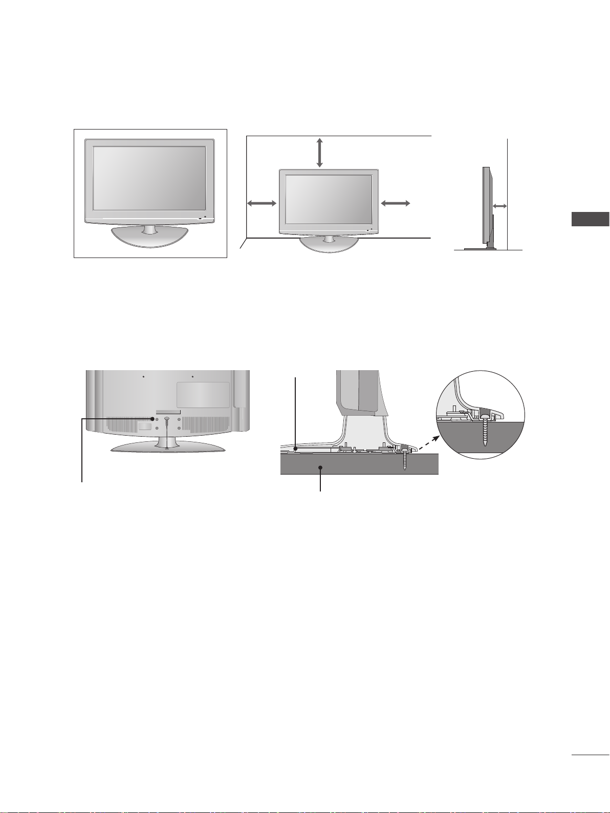
DESKTOP PEDESTAL INSTALLATION
P R
VO L
O K
M E N U
IN P U T
/I
For adequate ventilation allow a clearance of 4” (10cm) all around the TV.
4 inches
4 inches4 inches 4 inches
PREPERATION
ATTACHING THE TV TO A DESK (Only 32/37LF77
**
)
The TV must be attached to desk so it cannot be pulled in a forward/backward direction, potentially causing injury or
damaging the product. Use only an attached screw.
Stand
1-Screw
(provided as parts of the product)
Desk
WARNING
To prevent TV from falling over, the TV should be securely attached to the floor/wall per installation instructions.
►
Tipping, shaking, or rocking the machine may cause injury.
GB-7
PREPARATION
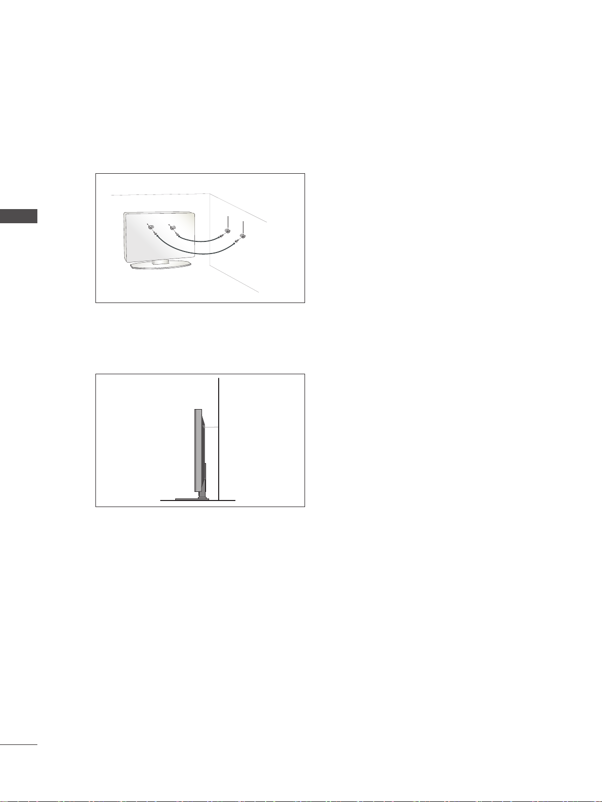
CAREFUL INSTALLATION ADVICE
You should purchase necessary components to fix the TV safety and secure to the wall on the market.
■
Position the TV close to the wall to avoid the possibility of it falling when pushed.
■
The instructions shown below are a safer way to set up the TV, by fixing it to the wall, avoiding the possibility of it falling
■
forwards if pulled. This will prevent the TV from falling forward and causing injury. This will also prevent the TV from
damage. Ensure that children do not climb or hang from the TV.
1
PREPERATION
2
Use the eye-bolts or TV brackets/bolts to fix the product to the wall as shown in the picture.
➊
(If your TV has bolts in the eyebolts, loosen these bolts.)
* Insert the eye-bolts or TV brackets/bolts and tighten them securely in the upper holes.
Secure the wall brackets with the bolts on the wall. Match the height of the bracket that is mounted on the wall.
➋
3
GB-8
Use a sturdy rope to tie the product for alignment. It is safer to tie the rope so it becomes horizontal between the
➌
wall and the product.
NOTE
When moving the TV undo the cords first.
►
Use a platform or cabinet strong and large enough to support the size and weight of the TV.
►
To use the TV safely make sure that the height of the bracket on the wall and on the TV is the same.
►
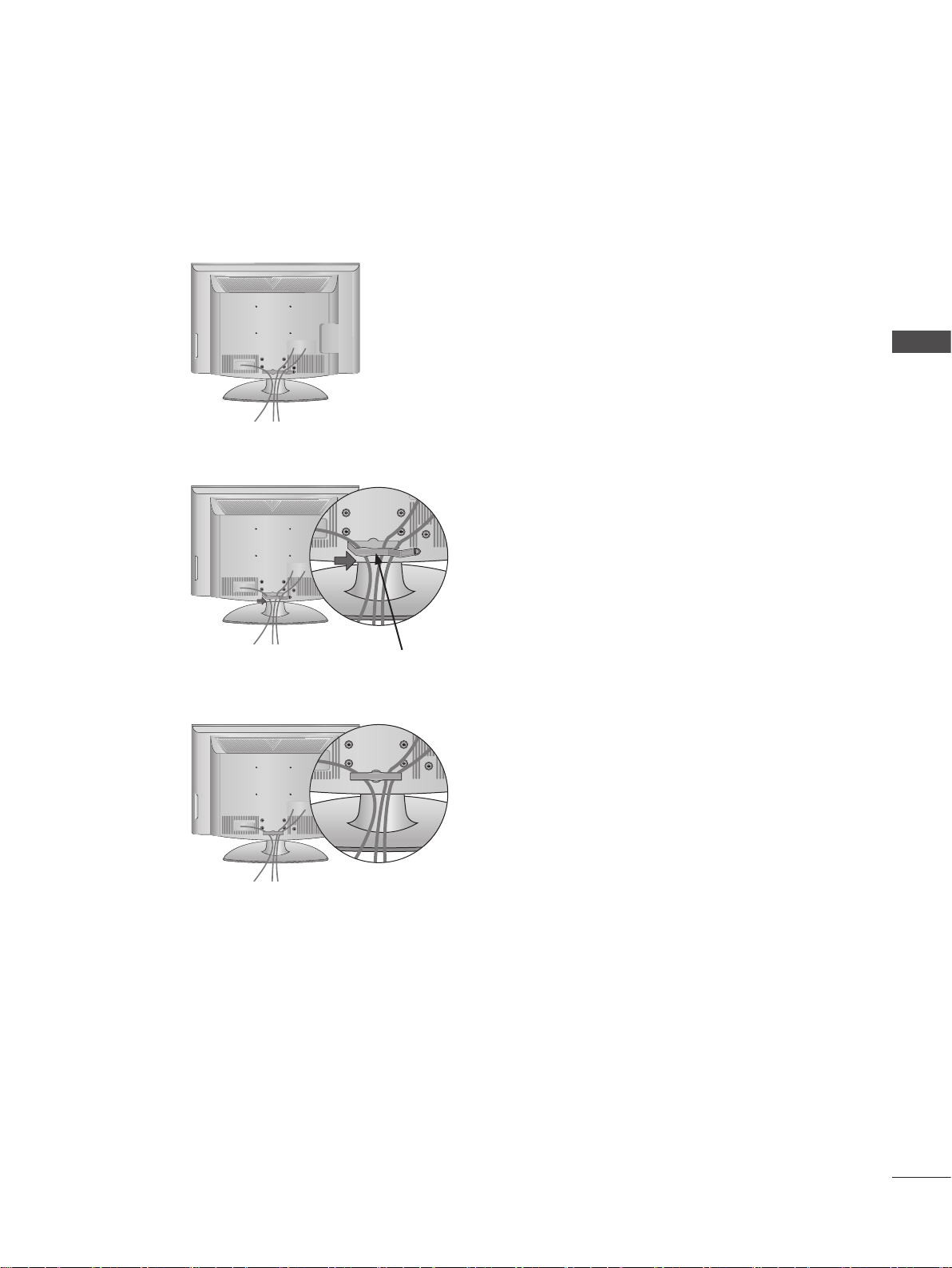
BACK COVER FOR WIRE ARRANGEMENT
Image shown may differ from your TV.
■
Connect the cables as necessary.
➊
To connect additional equipment, see the External Equipment Setup section.
Install the CABLE MANAGEMENT CLIP as shown.
➋
PREPERATION
CABLE MANAGEMENT CLIP
Fit the CABLE MANAGEMENT CLIP as shown.
➌
NOTE
Do not use the CABLE MANAGEMENT CLIP to lift the TV.
►
- If the TV is dropped, you may be injured or the TV may be damaged.
GB-9

PREPARATION
SWIVEL STAND
Image shown may differ from your TV.
■
After installing the TV, you can adjust the TV manually to the left or
right direction by 20 degrees to suit your viewing position.
PREPERATION
NOT USING THE DESKTYPE STAND
Image shown may differ from your TV.
■
When installing the wall-mounted unit, use the protection cover.
or
Insert the PROTECTION COVER into the TV until clicking sound.
GB-10
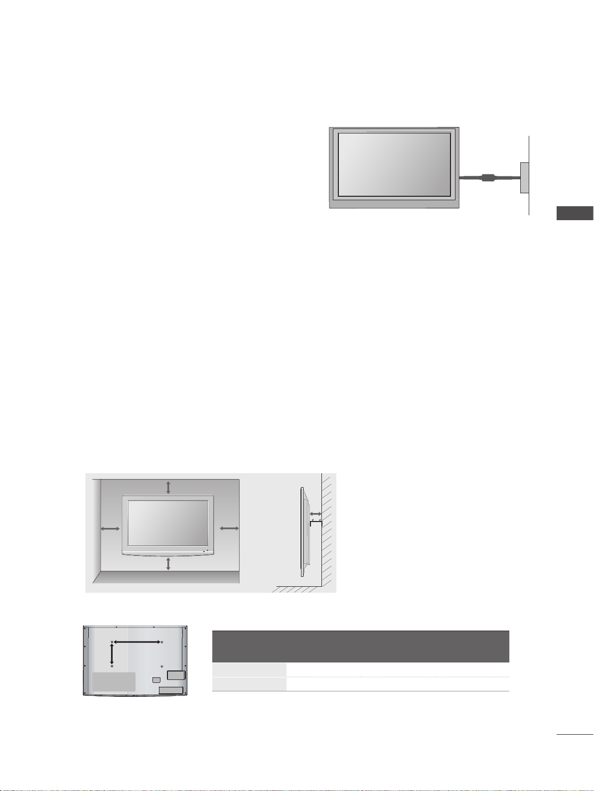
The TV can be installed in various ways such as on a wall, or on a desktop etc.
AA
BB
■
The TV is designed to be mounted horizontally.
■
EARTHING
Ensure that you connect the earth wire to prevent
possible electric shock. If grounding methods are not
possible, have a qualified electrician install a separate
Power Supply
circuit breaker.
Do not try to earth the TV by connecting it to telephone
Circuit breaker
wires, lightening rods or gas pipes.
WALL MOUNT: HORIZONTAL INSTALLATION
We recommend the use of a LG Brand wall mounting bracket when mounting the TV to a wall.
■
We recommend that you purchase a wall mounting bracket which supports VESA standard.
■
LG recommends that wall mounting be performed by a qualified professional installer.
■
NOTE
Should Install wall mount on a solid wall perpendicular to the floor.
►
Should use a special wall mount, if you want to install it to ceiling or slanted wall.
►
The surface that wall mount is to be mounted on should be of sufficient strength to support the weight of TV set; e.g.
►
concrete, natural rock, brick and hollow block.
Installing screw type and length depends on the wall mount used. Further information, refer to the instructions
►
included with the mount.
LG is not liable for any accidents or damage to property or TV due to incorrect installation:
►
- Where a non-compliant VESA wall mount is used.
- Incorrect fastening of screws to surface which may cause TV to fall and cause personal injury.
- Not following the recommended Installation method.
PREPERATION
4 inches
4 inches
4 inches
4 inches
Model
32LF77
**
37/42/47LF77
**
4 inches
VESA
(A * B)
200 * 100 M4 4
200 * 200 M6 4
Standard
Screw
Quantity
GB-11
PREPARATION
To prevent damage do not connect to the mains outlet until all connections are made between the devices.
■
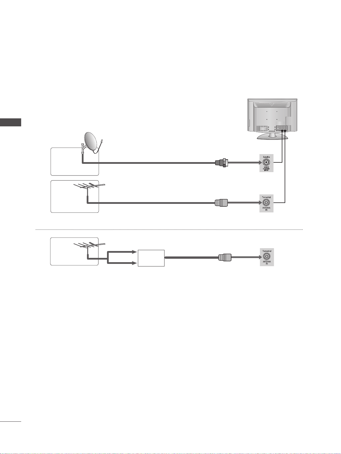
ANTENNA CONNECTION
For optimum picture quality, adjust antenna direction.
■
An antenna cable and converter are not supplied.
■
PREPERATION
Satellite
Dish
Terrestrial
Antenna
Terrestrial
Antenna
■
In poor signal areas, to achieve better picture quality it may be necessary to install a signal amplifier to the antenna as
shown above.
If signal needs to be split for two TVs, use an antenna signal splitter for connection.
■
Satellite RF Coaxial Cable (75 ohm)
Terrestrial RF Coaxial Cable (75 ohm)
UHF
Signal
Amplifier
VHF
GB-12
EXTERNAL EQUIPMENT SETUP
To avoid damaging any equipment, never plug in any power cord until you have finished connecting all equipment.
■
This section on EXTERNAL EQUIPMENT SETUP mainly uses diagrams for 37LF77** model.
■
Image shown may differ from your TV.
■
HD RECEIVER SETUP
This TV can receive Digital RF/Cable signals without an external digital set-top box. However, if you do receive Digital
■
signals from a digital set-top box or other digital external device, refer to the diagram as shown below.
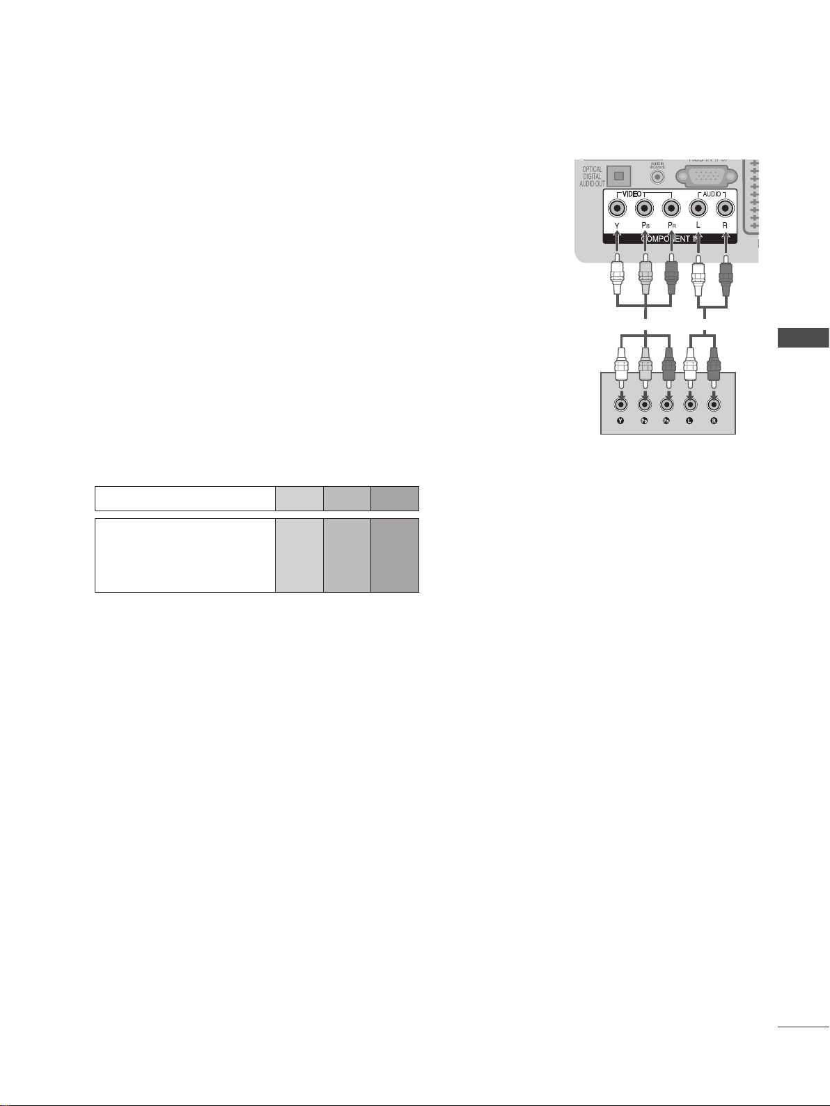
Connecting with a component cable
Connect the video outputs (Y, PB, PR) of the digital set top box to the
➊
COMPONENT IN VIDEO jacks on the TV.
Connect the audio outputs of the digital set-top box to the COMPONENT IN
➋
AUDIO jacks on the TV.
Turn on the digital set-top box. (Refer to the owner’s manual for the digital set-top
➌
box.)
Select Component input source using the INPUT button on the remote control.
➍
➊
EXTERNAL EQUIPMENT SETUP
➋
Signal Component HDMI
480i/576i O X
480p/576p O O
720p/1080i O O
1080p
O
(50/60Hz only)
(24Hz/30Hz/50Hz/60Hz)
O
GB-13
GB-14
EXTERNAL EQUIPMENT SETUP
EXTERNAL EQUIPMENT SETUP
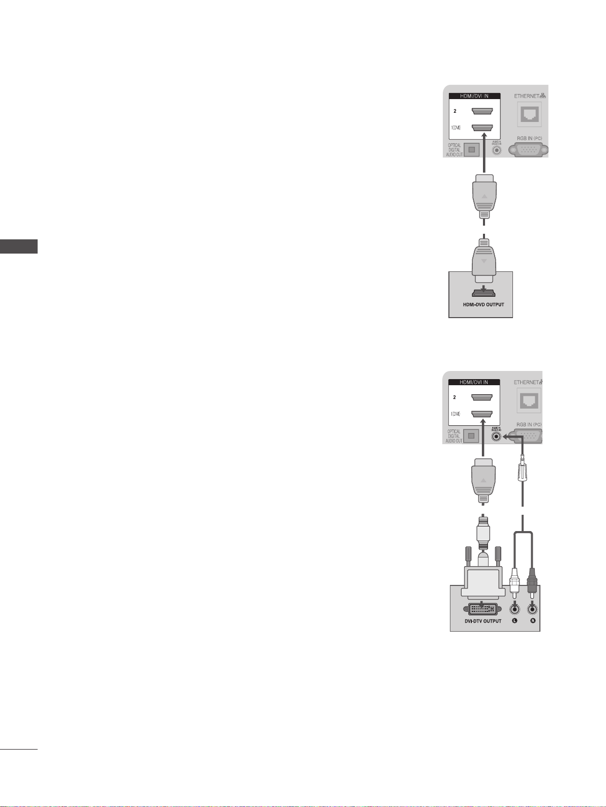
Connecting a set-top box with an HDMI cable
Connect the digital set-top box to HDMI/DVI IN 1, HDMI IN 2 or HDMI IN 3 jack
➊
on the TV.
Turn on the digital set-top box.
➋
(Refer to the owner’s manual for the digital set-top box.)
Select HDMI1, HDMI2 or HDMI3 input source using the INPUT button on the
➌
remote control.
NOTE
Check that your HDMI cable is version 1.3 or higher. If the HDMI cables don’t support
►
HDMI version 1.3, flickering or no screen display can result. Please use the latest
cables that support at least HDMI version 1.3.
➊
Connecting with an HDMI to DVI cable
Connect the digital set-top box to HDMI/DVI IN 1 jack on the TV.
➊
Connect the audio output of the digital set-top box to the AUDIO IN (RGB/DVI) jack
➋
on the TV.
Turn on the digital set-top box.
➌
(Refer to the owner’s manual for the digital set-top box.)
Select HDMI 1 input source using the INPUT button on the remote control.
➍
➊
➋
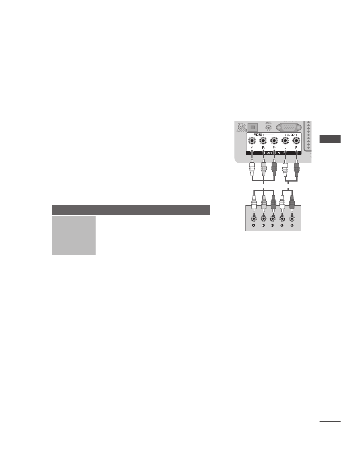
DVD SETUP
Connecting with a component cable
Connect the video outputs (Y, PB, PR) of the DVD to the COMPONENT IN
➊
VIDEO jacks on the TV.
Connect the audio outputs of the DVD to the COMPONENT IN AUDIO jacks on
➋
the TV.
Turn on the DVD player, insert a DVD.
➌
Select Component input source using the INPUT button on the remote control.
➍
Refer to the DVD player’s manual for operating instructions.
➎
Component Input ports
To achieve better picture quality, connect a DVD player to the component input ports as
shown below.
➊ ➋
EXTERNAL EQUIPMENT SETUP
Component ports on the TV
Video output ports
on DVD player
Y PB PR
Y
Y
Y
Y
PB
B-Y
Cb
Pb
R-Y
PR
Cr
Pr
GB-15

GB-16
EXTERNAL EQUIPMENT SETUP
EXTERNAL EQUIPMENT SETUP
Connecting with a Euro Scart cable
Connect the Euro scart socket of the DVD to the AV1 Euro scart socket on the
➊
TV.
Turn on the DVD player, insert a DVD.
➋
Select AV1 input source using the INPUT button on the remote control.
➌
If connected to AV2 Euro scart socket, select AV2 input source.
Refer to the DVD player’s manual for operating instructions.
➍
NOTE
Any Euro scart cable used must be signal shielded.
►
➊
Scart Output
Freesat ( DTV)
Non-Freesat ( DTV)
Digital Antenna ( DTV)
Analogue Antenna ( TV)
Connecting the HDMI cable
Connect the HDMI output of the DVD to the HDMI/DVI IN 1, HDMI IN 2 or
➊
HDMI IN 3 jack on the TV.
Main Input AV1 (SCART1 Output) AV2 (SCART2 Output)
Mute
Mute
Mute
AV1(SCART1) AV1
AV2(SCART2) AV2
Component Mute
RGB Mute
AV3(CVBS Side) AV3
HDMI1
HDMI2 Mute
HDMI3(Side) Mute
(Analogue Antenna ( TV) if
the TV mode you last watched
is Analogue Antenna mode.)
Mute
Freesat ( DTV)
Non-Freesat ( DTV)
Digital Antenna ( DTV)
Analogue Antenna ( TV)
Mute
Select HDMI1, HDMI2 or HDMI3 input source using the INPUT button on
➋
the remote control.
Refer to the DVD player’s manual for operating instructions.
➌
NOTE
The TV can receive video and audio signals simultaneously when using a
►
HDMI cable.
If the DVD does not support Auto HDMI, you must set the output resolution
►
appropriately.
Check that your HDMI cable is version 1.3 or higher. If the HDMI cables don’t
►
support HDMI version 1.3, flickering or no screen display can result. Please
use the latest cables that support at least HDMI version 1.3.
➊
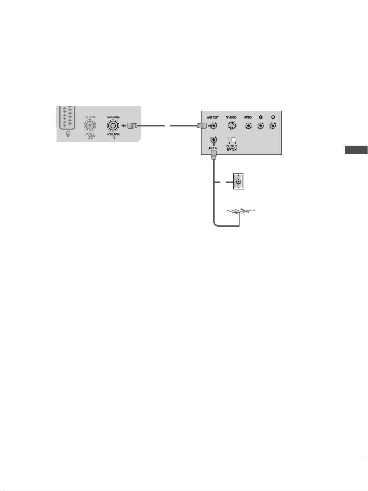
VCR SETUP
To avoid picture noise (interference), allow adequate distance between the VCR and TV.
■
Connecting with a Terrestrial RF Cable
➊
➋
EXTERNAL EQUIPMENT SETUP
Terrestrial
Wall jack
Terrestrial Antenna
Connect the ANT OUT socket of the VCR to the ANTENNA IN socket on the TV.
➊
Connect the terrestrial antenna cable to the ANT IN socket of the VCR.
➋
Press the PLAY button on the VCR and match the appropriate channel between the TV and VCR for viewing.
➌
GB-17

GB-18
EXTERNAL EQUIPMENT SETUP
EXTERNAL EQUIPMENT SETUP
Connecting with a Euro Scart cable
Connect the Euro scart socket of the VCR to the AV1 Euro scart socket on the
➊
TV.
Insert a video tape into the VCR and press PLAY on the VCR.
➋
(Refer to the VCR owner’s manual.)
Select AV1 input source using the INPUT button on the remote control.
➌
If connected to AV2 Euro scart socket, select AV2 input source.
➍
NOTE
Any Euro Scart cable used must be signal shielded.
►
Scart Output
Main Input AV1 (SCART1 Output) AV2 (SCART2 Output)
Freesat ( DTV)
Mute
➊
Freesat ( DTV)
Non-Freesat ( DTV)
Digital Antenna ( DTV)
Analogue Antenna ( TV)
AV1(SCART1) AV1
AV2(SCART2) AV2
Component Mute
RGB Mute
AV3(CVBS Side) AV3
HDMI1
HDMI2 Mute
HDMI3(Side) Mute
(Analogue Antenna ( TV) if
the TV mode you last watched
is Analogue Antenna mode.)
Mute
Mute
Mute
Connecting with a RCA cable
Connect the AUDIO/VIDEO jacks between TV and VCR. Match the jack
➊
colours (Video = yellow, Audio Left = white, and Audio Right = red)
Insert a video tape into the VCR and press PLAY on the VCR. (Refer to the
➋
VCR owner’s manual.)
Non-Freesat ( DTV)
Digital Antenna ( DTV)
Analogue Antenna ( TV)
Mute
➊
Select AV3 input source using the INPUT button on the remote control.
➌
NOTE
If you have a mono VCR, connect the audio cable from the VCR to the
►
AUDIO L/MONO jack of the TV.
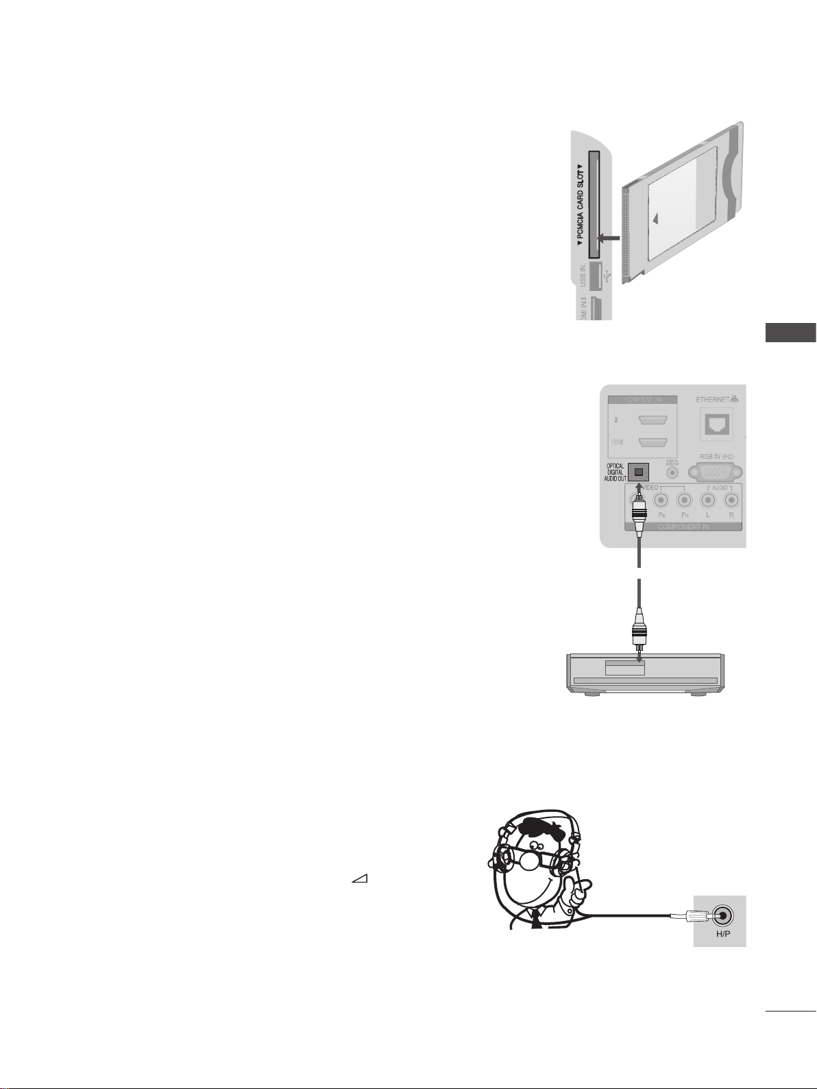
INSERTION OF CI MODULE
- To view the encrypted (pay) services in digital TV mode.
- This feature is not available in all countries.
Insert the CI Module to PCMCIA (Personal Computer Memory Card International
➊
Association) CARD SLOT of TV as shown.
For further information, see p.51.
NOTE
Check if the CI module is inserted into the PCMCIA card slot in the right direction.
►
If the module is not inserted properly, this can cause damage to the TV and the
PCMCIA card slot.
DIGITAL AUDIO OUT SETUP
Sending the TV’s digital audio signal to external audio equipment via the Digital
Audio Output (Optical) port.
If you want to enjoy digital broadcasting through 5.1-channel speakers, connect the
OPTICAL DIGITAL AUDIO OUT terminal on the back of TV to a Home Theater (or
amp).
Connect one end of an optical cable to the TV Digital Audio (Optical) Output
➊
port.
➊
EXTERNAL EQUIPMENT SETUP
Connect the other end of the optical cable to the digital audio (Optical) input on
➋
the audio equipment.
Set the “TV Speaker option - Off ” in the AUDIO menu.(►p.85). Refer to the
➌
external audio equipment instruction manual for operation.
CAUTION
Do not look into the optical output port. Looking at the laser beam may damage
►
your vision.
HEADPHONE SETUP
You can listen the sound through the headphone.
Plug the headphone into the headphone socket.
➊
To adjust the headphone volume, press the + or - button.
➋
If you press the MUTE button, the sound from the headphone is
switched off.
➊
GB-19
GB-20
EXTERNAL EQUIPMENT SETUP
EXTERNAL EQUIPMENT SETUP
L R
VIDEO
H/P
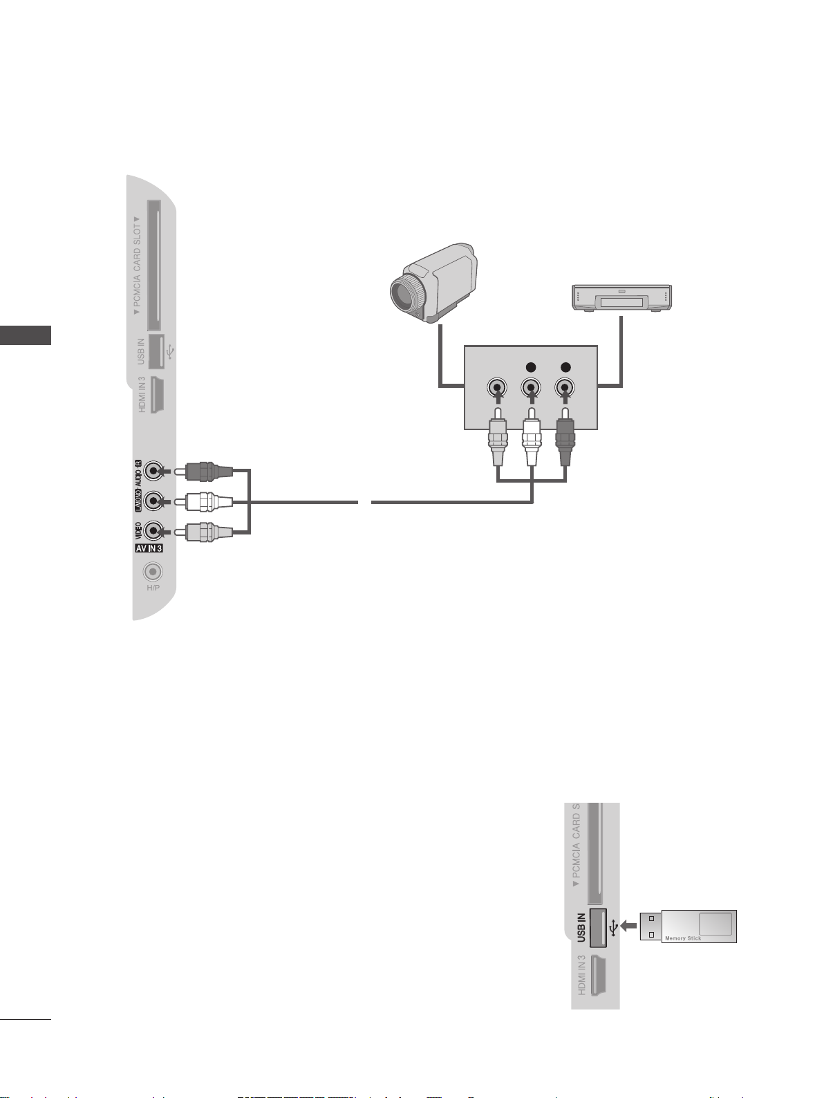
OTHER A/V SOURCE SETUP
Camcorder
Video Game Set
➊
Connect the AUDIO/VIDEO jacks between TV and external equipment. Match the jack colours. (Video = yellow,
➊
Audio Left = white, and Audio Right = red)
Select AV3 input source using the INPUT button on the remote control.
➋
Operate the corresponding external equipment.
➌
(Refer to external equipment operating guide.)
USB SETUP
Connect the USB device to the USB IN jack on the side of the TV.
➊
After connecting the USB IN jack, you use the USB function. (►p.59)
➋
➊
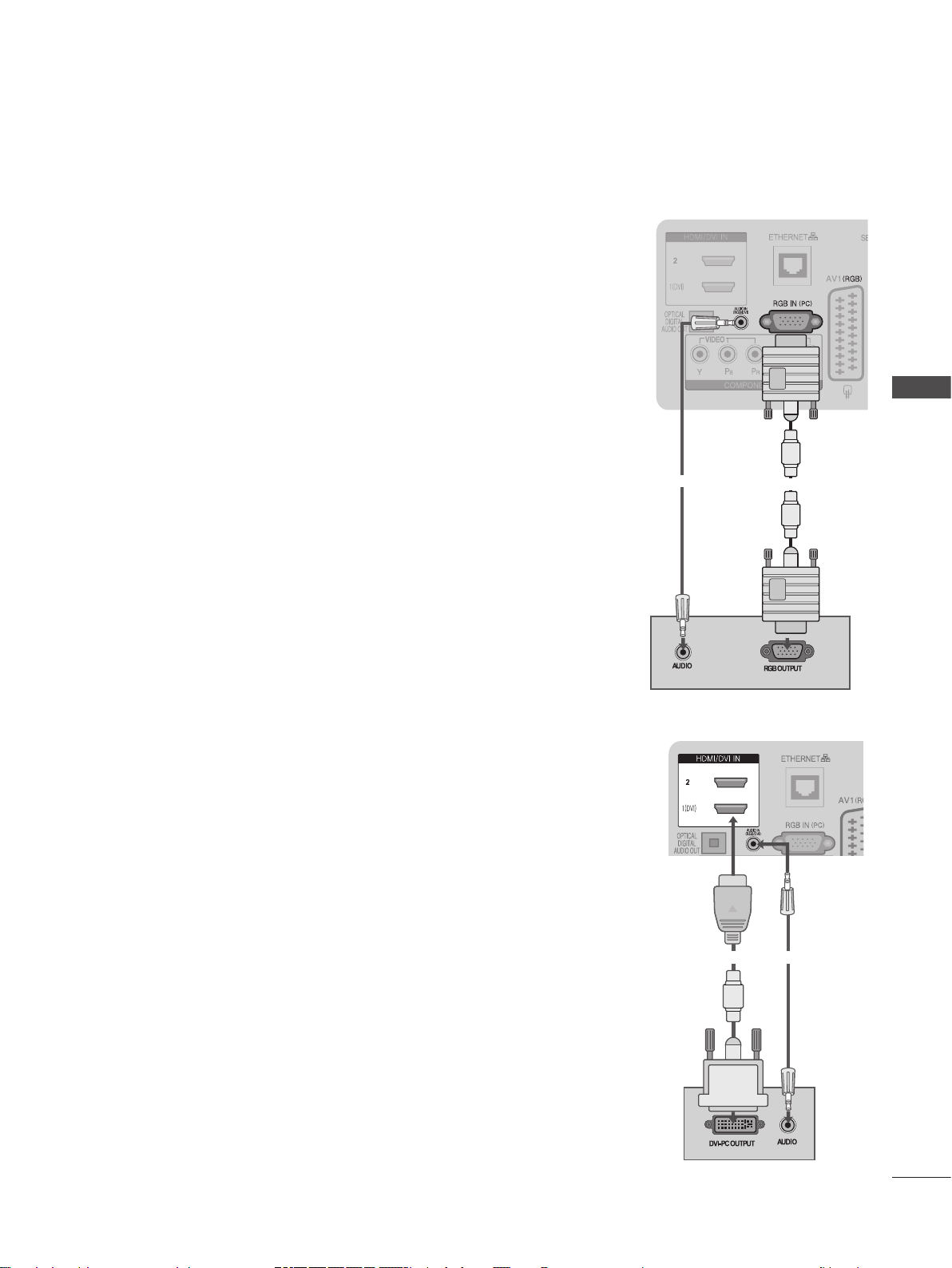
PC SETUP
This TV provides Plug and Play capability, meaning that the PC adjusts automatically to the TV’s settings.
Connecting with a D-sub 15 pin cable
Connect the RGB output of the PC to the RGB IN (PC) jack on the TV.
➊
Connect the PC audio output to the AUDIO IN (RGB/DVI) jack on the TV.
➋
Turn on the PC and the TV
➌
Select RGB input source using the INPUT button on the remote control.
➍
EXTERNAL EQUIPMENT SETUP
Connecting with an HDMI to DVI cable
Connect the DVI output of the PC to the HDMI/DVI IN 1 jack on the TV.
➊
Connect the PC audio output to the AUDIO IN (RGB/DVI) jack on the TV.
➋
Turn on the PC and the TV.
➌
Select HDMI 1 input source using the INPUT button on the remote control.
➍
➋
➊
➊
➋
GB-21

GB-22
EXTERNAL EQUIPMENT SETUP
EXTERNAL EQUIPMENT SETUP
Supported Display Resolution
RGB(PC), HDMI1(DVI) -PC mode
Resolution
720 x 400 31.468 70.08
640 x 480 31.469 59.94
800 x 600 37.879 60.31
1024 x 768 48.363 60.00
1280 x 768 47.78 59.87
1360 x 768 47.72 59.80
1280 x 1024 63.98 60.02
1400 x 1050 65.317 59.979
1920 x 1080 66.587 59.937
Component mode
Resolution
720 x 480
720 x 576
1280 x 720
1920 x 1080
Horizontal
Frequency(kHz)
Horizontal
Frequency(kHz)
15.73
15.75
31.47
31.50
15.6
31.25
37.50
44.96
45.00
33.72
33.75
28.125
56.25
67.433
67.500
Vertical
Frequency(Hz)
Vertical
Frequency(Hz)
59.9
60
59.9
60
50
50
50.00
59.94
60.00
59.94
60.00
50.00
50.00
59.94
60.00
HDMI2, HDMI3 -DTV mode
Resolution
640 x 480
720 x 480
720 x 576 31.25 50.00
1280 x 720
1920 x 1080
Horizontal
Frequency(kHz)
31.649
31.469
31.47
31.50
37.50
44.96
45.00
28.125
33.72
33.75
27.00
33.750
56.25
67.433
67.50
Frequency(Hz)
Vertical
59.9
60
59.94
60
50.00
50.94
60
50.00
59.94
60
24.00
30
50.00
59.94
60

NOTE :
Avoid keeping a fixed image on the TV’s screen for
►
prolonged periods of time. The fixed image may
become permanently imprinted on the screen; use a
screen saver when possible.
There may be interference relating to resolution,
►
vertical pattern, contrast or brightness in PC mode.
Change the PC mode to another resolution or
change the refresh rate to another rate or adjust
the brightness and contrast on the menu until the
picture is clear. If the refresh rate of the PC graphic
card can not be changed, change the PC graphic
card or consult the manufacturer of the PC graphic
card.
The synchronization input waveform for Horizontal
►
and Vertical frequencies are separate.
We recommend using 1920x1080, 60Hz for the PC
►
mode, this should provide the best picture quality.
Connect the signal cable from the monitor output
►
port of the PC to the RGB IN(PC) port of the TV or
the signal cable from the HDMI output port of the
PC to the HDMI/DVI IN 1(DVI) port on the TV.
Connect the audio cable from the PC to the AUDIO
►
IN (RGB/DVI) on the TV. (Audio cables are not
included with the TV).
If using a sound card, adjust PC sound as required.
►
This TV uses a VESA Plug and Play Solution. The
►
TV provides EDID data to the PC system with a
DDC protocol. The PC adjusts automatically when
using this TV.
DDC protocol is preset for RGB (Analogue RGB),
►
HDMI (Digital RGB) mode.
If required, adjust the settings for Plug and Play
►
functionality.
If the graphic card on the PC does not output
►
analogue and digital RGB simultaneously, connect
only one of either RGB IN or HDMI/DVI IN 1(DVI) to
display the PC output on the TV.
If the graphic card on the PC does output analogue
►
and digital RGB simultaneously, switch the TV to
either RGB or HDMI; (the other mode is set to Plug
and Play automatically by the TV.)
DOS mode may not work depending on the video
►
card if you use a HDMI to DVI cable.
If you use too long an RGB-PC cable, there may be
►
interference on the screen. We recommend using
under 5m of cable. This provides the best picture
quality.
EXTERNAL EQUIPMENT SETUP
GB-23
GB-24
EXTERNAL EQUIPMENT SETUP
EXTERNAL EQUIPMENT SETUP
MENU
OK
OK
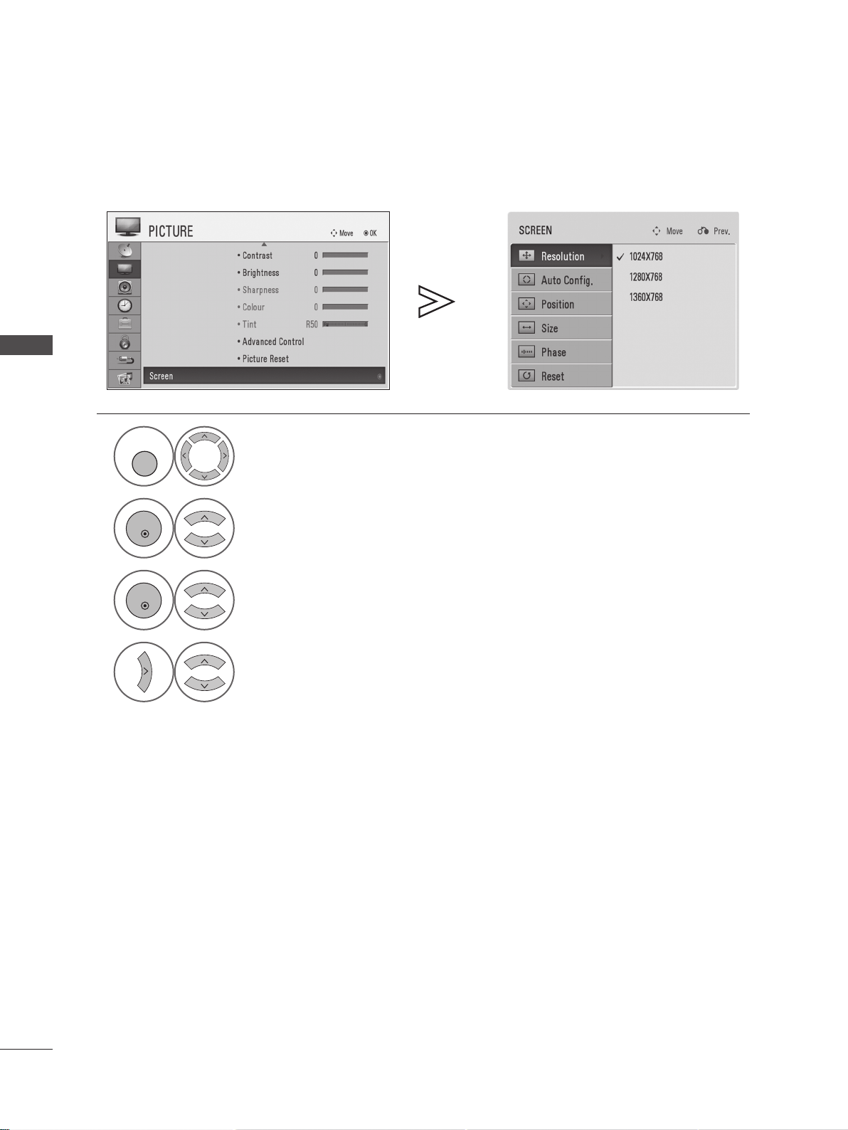
Screen Setup for PC mode (In RGB mode only)
Selecting Resolution
To view a normal picture, match the resolution of RGB mode and resolution of PC.
1
2
3
4
Select PICTURE.
Select Screen.
Select Resolution.
Select the desired resolution.
• Press the MENU or EXIT button to return to normal TV viewing.
• Press the RETURN button to return to the previous screen.

Auto Congure
MENU
OK
OK
OK
OK
Automatically optimizes the display. This is recommended for the first time connecting to a PC.
EXTERNAL EQUIPMENT SETUP
1
2
3
4
5
Select PICTURE.
Select Screen.
Select Auto Config..
Select Yes.
Run Auto Config..
• If the picture is not clear after auto
conguration, adjust the position, size or
phase of picture manually.
• Press the MENU or EXIT button to return to normal TV viewing.
• Press the RETURN button to return to the previous screen.
GB-25

GB-26
EXTERNAL EQUIPMENT SETUP
EXTERNAL EQUIPMENT SETUP
MENU
OK
OK
Adjustment for screen Position, Size, Phase
If the picture is not clear after auto adjustment and especially if characters are still trembling, adjust the picture phase
manually.
1
2
3
4
Select PICTURE.
Select Screen.
Select Position, Size or Phase.
Make appropriate adjustments.
• Press the MENU or EXIT button to return to normal TV viewing.
• Press the RETURN button to return to the previous screen.

Screen Reset
MENU
OK
OK
OK
OK
Returns Position, Size and Phase to the factory default settings.
EXTERNAL EQUIPMENT SETUP
1
2
3
4
5
Select PICTURE.
Select Screen.
Select Reset.
Select Yes.
Run Reset.
• Press the MENU or EXIT button to return to normal TV viewing.
• Press the RETURN button to return to the previous screen.
GB-27

WATCHING TV / PROGRAMME CONTROL
REMOTE CONTROL KEY FUNCTIONS
When using the remote control, aim it at the remote control sensor on the TV.
MODE
D/A
FREESAT
POWER
INPUT
TV/RAD
Switches to Antenna mode.
(Toggles between Digital and Analogue Antenna modes.)
Switches to Freesat mode.
(Toggles between Freesat and Non-Freesat modes.)
Switches the TV on from standby or off to standby.
Toggles between all AV inputs sequentially.
Switches between TV and Radio modes.
WATCHING TV / PROGRAMME CONTROL
Q. MENU
MENU
GUIDE
Up/Down/Left/Right
RETURN
INFO
TV Mode Explanation
This TV has 4 modes, and the On Screen Displays (OSD) and function may differ based
on the TV mode selected.
Select the desired quick menu source. (Aspect Ratio, Energy
Saving, Picture Mode, Sound Mode, Audio, Sleep Timer, Fav.
On/Off, USB Eject.) (►p.31)
Selects a menu.
Clears all on-screen displays and returns to TV viewing from
any menu.
Shows an electronic programme schedule. (►p.67)
Allows you to navigate the on-screen menus and adjust the
system settings to your preference.
Accepts your selection or displays the current mode.
OK
Allows the user to move back one step in an interactive
application, EPG or other user interaction function.
Shows the present screen information.
Clears all on-screen displays and returns to TV viewing.
EXIT
GB-28
TV Mode TV Service
Freesat
( DTV)
Non-Freesat
( DTV)
Digital Antenna
( DTV)
Analogue Antenna
( TV)
Free digital satellite broadcasts
(Free satellite programmes of Astra2 at 28.2° East)
Digital satellite broadcasts
(All satellite programmes of Astra2 at 28.2° East;
including Freesat programme)
Digital terrestrial broadcasts
(DVB)
Analogue terrestrial broadcasts
Switching
Button
Input List
(►p.56)
Connecting
Terminal
(►p.5, 12)

VOLUME
UP/DOWN
MARK
FAV
MUTE
Programme
UP/DOWN
PAGE
UP/DOWN
0~9 number buttons
LIST
Q.VIEW
Adjusts the volume.
Check and un-check programmes.
Displays the favourite programme list.
Switches the sound on or off.
Selects a programme.
Move from one full set of screen information to the next
one.
Selects a programme.
Selects numbered items in a menu.
Displays the programme table.
Returns to the previously viewed programme.
WATCHING TV / PROGRAMME CONTROL
Coloured
buttons
TELETEXT
BUTTONS
SUBTITLE
These buttons are used for Teletext, TV Guide,
Programme edit.
These buttons are used for teletext.
For further details, see the ‘Teletext’ section. (►p.99)
Recalls your preferred subtitle in digital mode.
AD
Switches on or off the audio description for people with
sight problems.
ENERGY SAVING
AV MODE
RATIO
Adjust the Energy saving mode of the TV.
It helps you select and set images and sounds when
connecting AV devices. (►p.57)
Selects your desired aspect ratio of picture.
Installing Batteries
Open the battery compartment cover on the rear and install the batteries paying
■
attention to the correct polarity.
Install two 1.5V AAA batteries. Do not mix old or used batteries with new ones.
■
Close cover.
■
GB-29
 Loading...