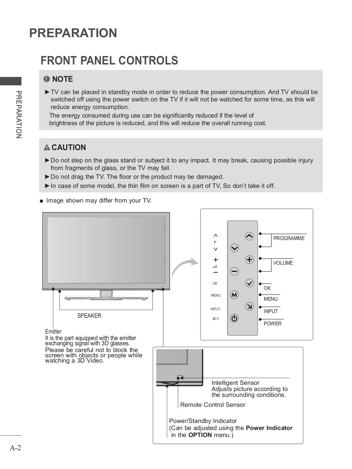
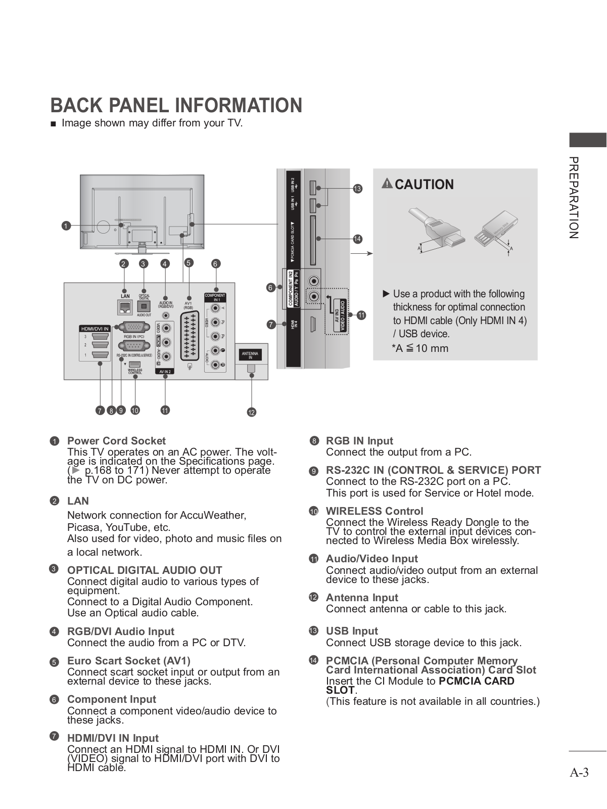
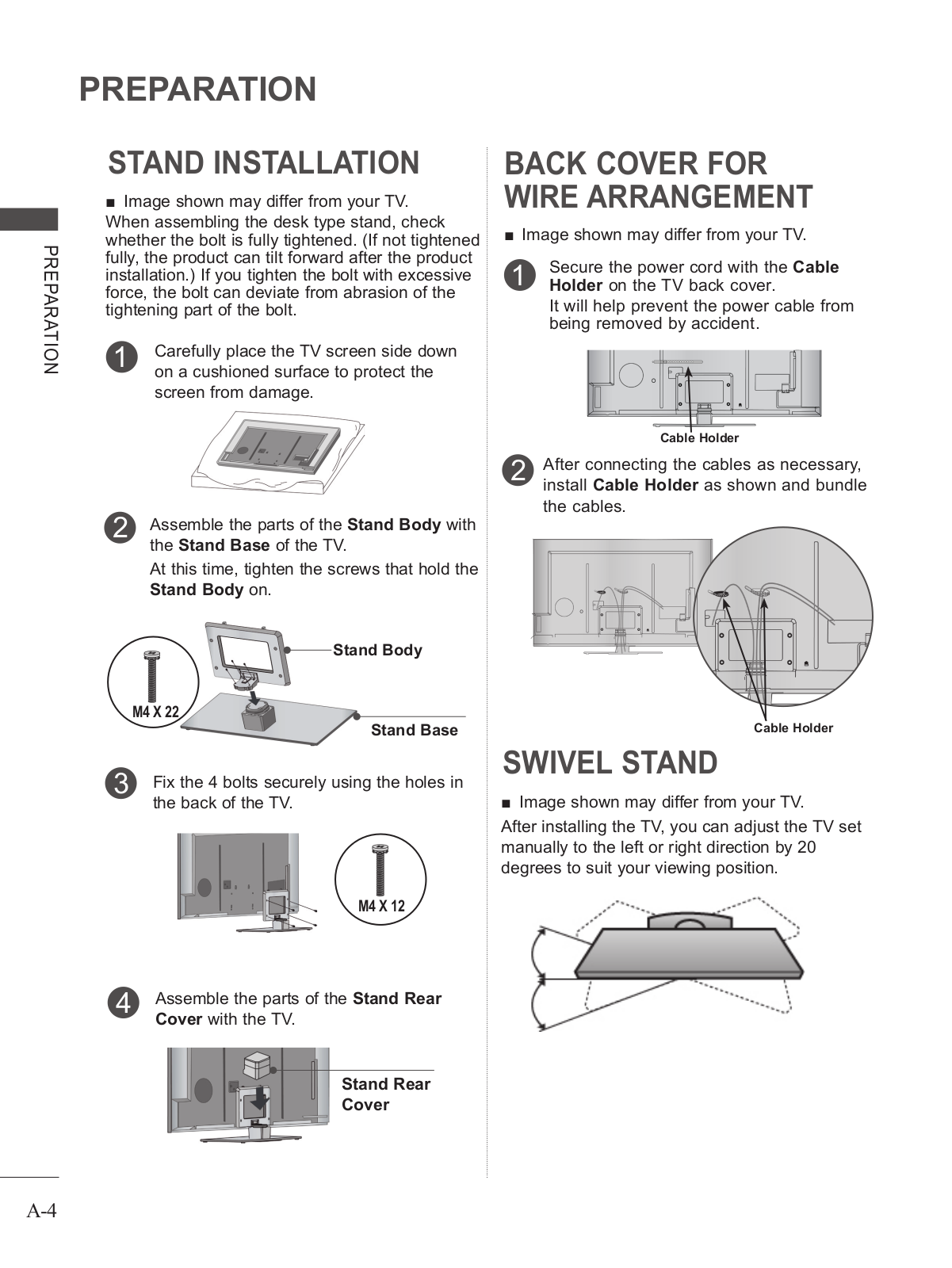
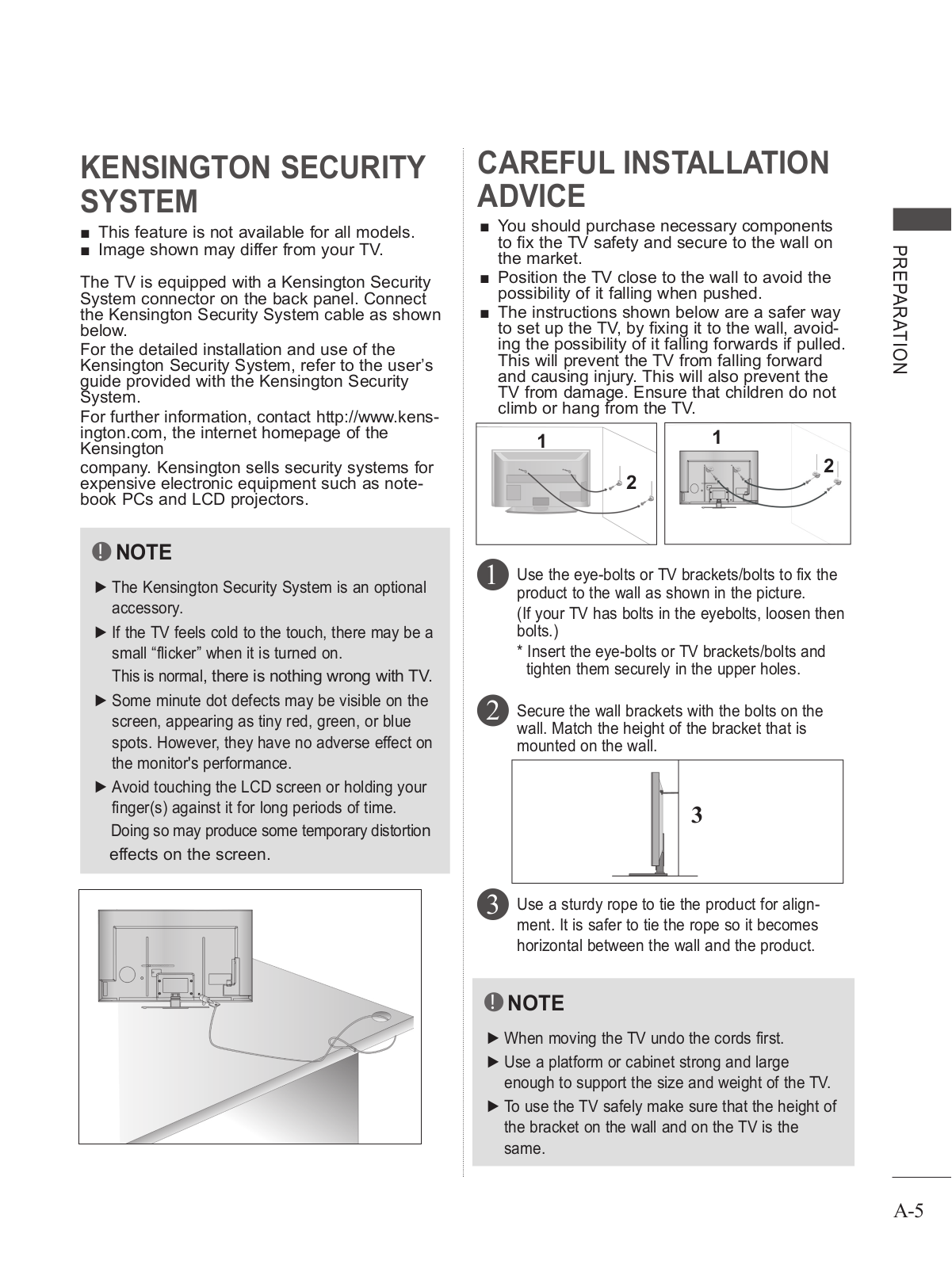
How it Works
Log In / Sign Up
Buy Points
How it Works
FAQ
Contact Us
Questions and Suggestions
Users
LG
Loading...
#
47LE5900
47LE7
47LE73
47LE7300
11
47LE7300-UA
2
47LE7300-ZA
3
47LE730N
4
47LE730N-ZA
3
47LE7380
3
47LE7380-ZA
3
47LE7390-ZA
47LE75
3
47LE7500
19
47LE7500-TA
47LE7500UC
47LE750C-TA
47LE750N
47LE750N-ZA
47LE750Q
3
47LE7510
4
47LE7510-ZB
47LE751N-ZB
47LE75 Series
47LE78
47LE7800
47LE7800-ZA
47LE7810-ZB
47LE78 Series
47LE79
47LE7900
47LE7900-ZA
47LE7910-ZB
47LE79 Series
47LE8
2
47LE8500
31
47LE8500-CA
47LE8500-TA
47LE8500UA
47LE8500-ZA
47LE850N
3
47LE850N-ZA
47LE8510-ZB
47LE851N-ZB
47LE8800-ZA
47LE8810-ZB
47LE8900
47LE8900-ZA
47LE8910-ZB
47LE8 Series
47LEVFB
47LEX8
16
47LEX89-ZA
47LEX8-CA
47LEX8N-ZA
47LEX8-UA
47LEX8-ZA
47LEXS
47LF11
4
47LF11-UA
2
47LF21
4
47LF51
14
47LF5100
2
47LF56 Series
2
47LF6
28
47LF60
47LF65
18
47LF65-ZC
2
47LF66
16
47LF66-ZE
47LF6 Series
47LF7700
4
47LF77 Series
2
47LG1
47LG1 Series
47LG20
47LG3
3
47LG30R
6
47LG30RA
47LG30RA-TA
47LG30R-TA
47LG32R
47LG33R-TC
47LG3RC-TA
47LG3 Series
47LG5
4
47LG50
53
47LG5000
9
47LG5000-ZA
9
47LG5010
9
47LG5010-ZD
6
47LG5020
4
47LG5020.BEU
47LG5020-ZB
5
47LG5030
9
47LG5030-ZE
8
47LG50D
2
47LG50DC
8
47LG50DC-UA
2
47LG50D-SA
47LG50 Series
5
Loading...
Loading...
Nothing found
47LEX8
User Manual
1 pgs
35.67 Kb
0
Owner's Manual
219 pgs
97.02 Mb
0
Owner's Manual
218 pgs
96.46 Mb
0
Owner's Manual
202 pgs
89.67 Mb
0
Owner's Manual
121 pgs
41.2 Mb
0
Owner's Manual
37 pgs
9.47 Mb
0
Owner's Manual
202 pgs
12.53 Mb
0
Owner's Manual
270 pgs
23.9 Mb
0
User Manual
224 pgs
38.83 Mb
0
Owner’s Manual [de]
210 pgs
37.89 Mb
0
User Manual [de]
210 pgs
62.65 Mb
0
User Manual [es]
210 pgs
38.79 Mb
0
Owner’s Manual [fr]
210 pgs
37.36 Mb
0
User Manual [it]
211 pgs
68.19 Mb
0
User Manual [nl]
210 pgs
62.48 Mb
0
User manual [pt]
94 pgs
6.15 Mb
0
Table of contents
Loading...
LG 47LEX8, 55LEX8 User Manual
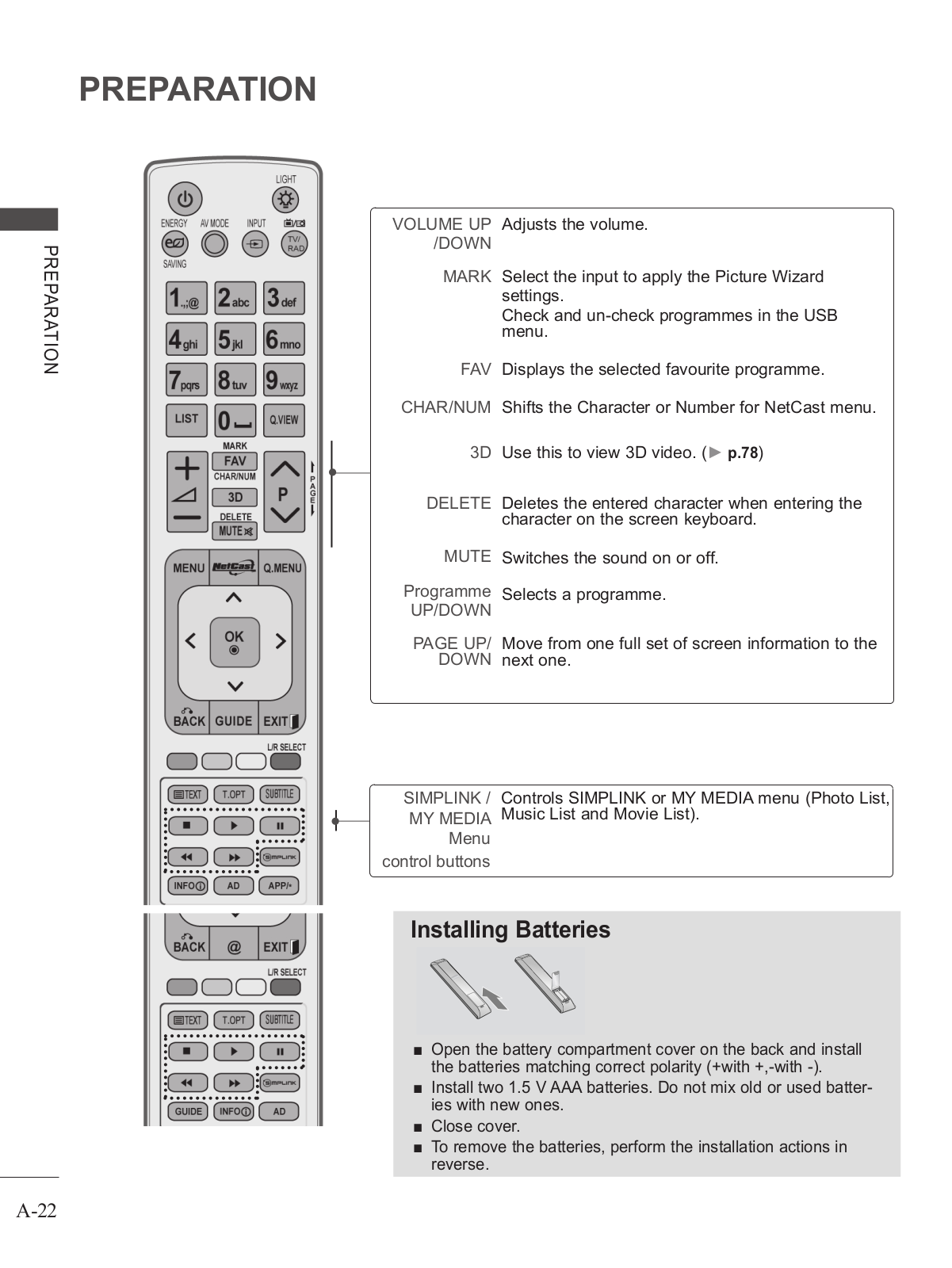
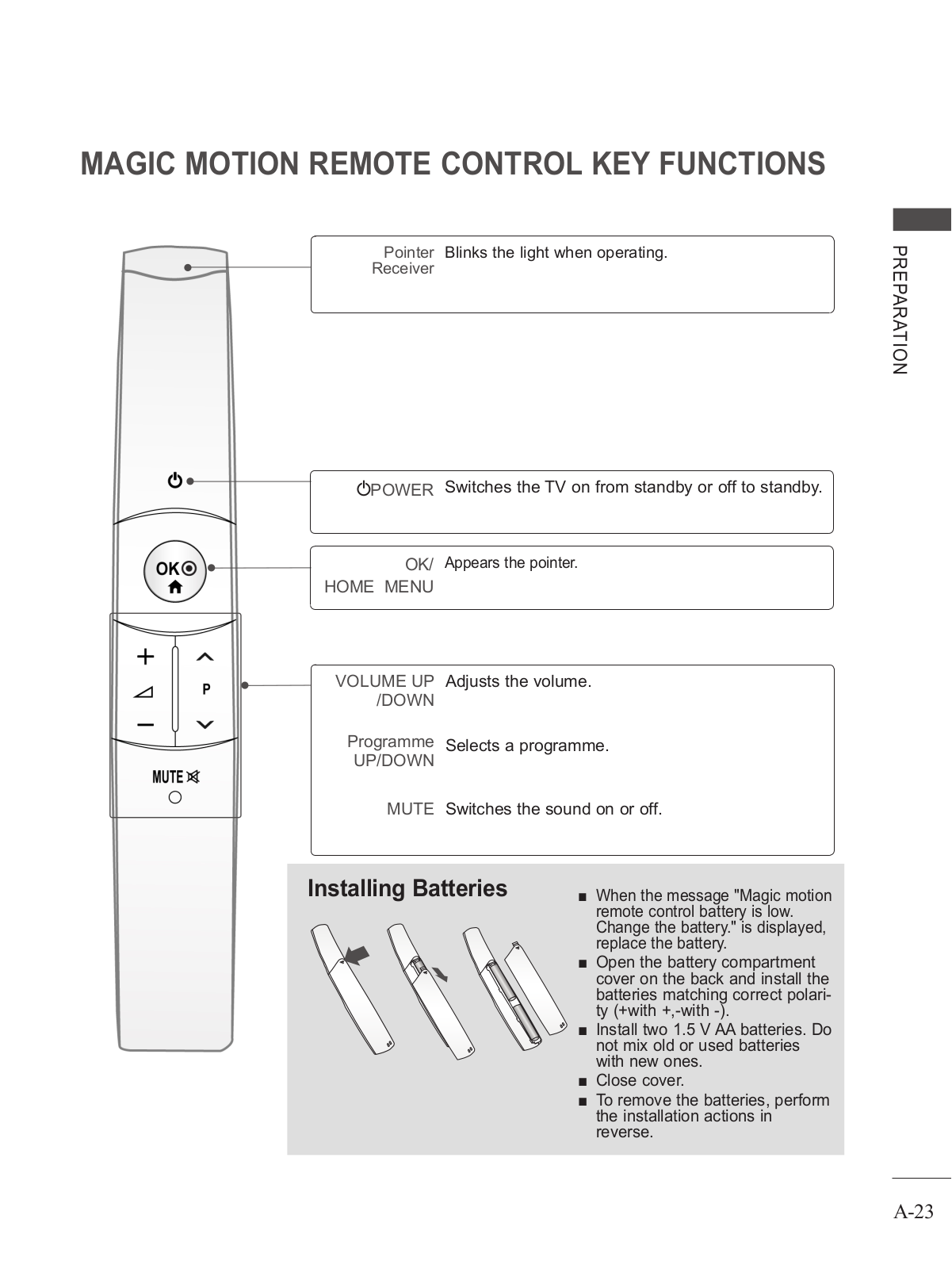
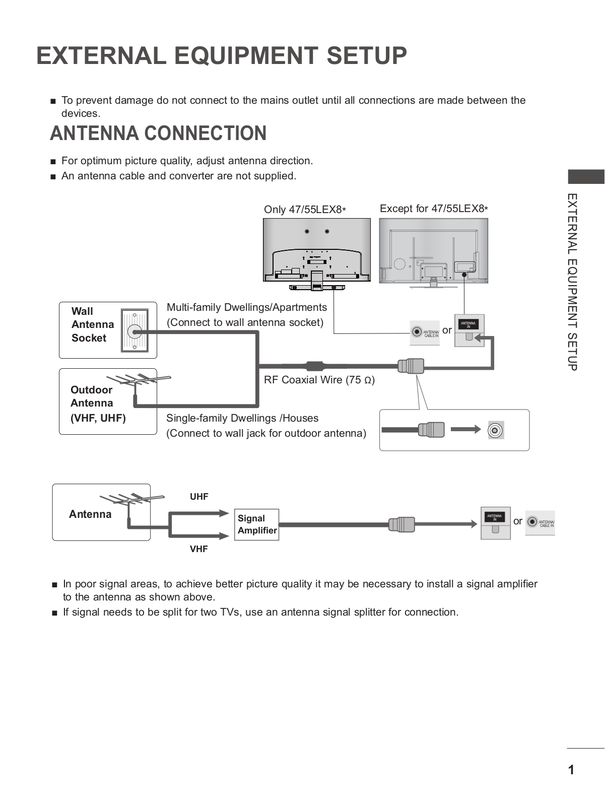
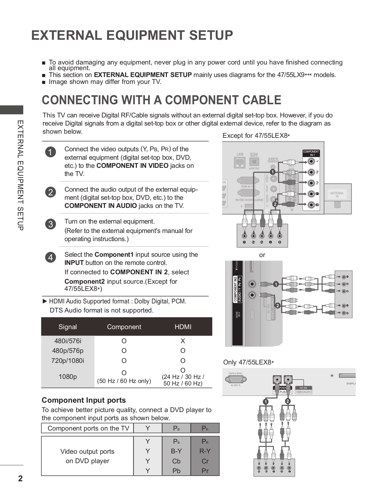
...
LG User Manual
Download
Specifications and Main Features
Frequently Asked Questions
User Manual
Download
Loading...
+
194
hidden pages
Unhide
You need points to download manuals.
1 point = 1 manual.
You can buy points or you can get point for every manual you upload.
Buy points
Upload your manuals
 Loading...