

LG 37lBSD, 42lBSD, 47lBSD, S2lBSD, 32lB4D Owner's Manual
...
LCD TV
ENERGYSTARisa
guidelines
Environmental Protection Agency(EPA).
setofpower-saving
issued by
the
AsanENERGY
Partner
has determined
product meets
ENERGY
energy
for
U.S.
LGEU.S.
STAR
guidelines
efficiency.
STAR
A.,lnc.
that
the
this
OWNER'S
I
LCD TV MODELS
37lBSD
/
S2lBSD
32lB4D
Please
your
set.
Retainitfor
Record
See
the
this
informationtoyour
when
An
extended
on
the
on
the
To
read
(PC)
equipped
/
read
this
future
model
label
you
require
owner's manual
advanced featuresoftheselGTV
CD-ROM providedinan electronic version.
these
files, you
MANUAL
42lBSD
37lB4D
manual
reference.
number
attachedonthe
servic
with a CD-ROM drive.
P/NO:
/
47lBSD
/
42lB4D
carefully
and
serial
back
dealer
that
will
needtouse personal
MFL35930210
before
numberofthe
contains information
operating
cover
and
quote
setsislocated
computer
(0706-REV04)
set.

WARNING
A
TO
REDUCE
DO NOT
USER
SERVICEABLE
QUALIFIED
A symbol, within an equilateral triangle,
presenceofuninsulated "dangerous voltage
within
the
sufficient magnitudetoconstitute a
to
shock
the
presenceofimportant operating
tenance
accompanying
WARNING/CAUTION
TO REDUCE THE
SHOCK,
RAINORMOISTURE.
NOTE
THE
REMOVE
The
lightning flash with arrowhead
is
intendedtoalert
product's enclosure
persons.
The exclamation point
triangle
(servicing) instructionsinthe
DO
NOT EXPOSE THIS PRODUCT TO
TO
CABLE/TV
/
CAUTION
RISKOFELECTRIC
COVER (OR
PARTS
INSIDE.
SERVICE
is
intendedtoalert
the
appliance.
RISKOFFIRE
PERSONNEL
the
that
within
INSTALLER
SHOCK
BACK).
REFER
usertothe
maybeof
riskofelectric
an equilateral
the
and
main-
literature
AND
ELECTRIC
NO
n
user
TO
to
WARNING/CAUTION
To
prevent
this
FCC
Class B digital device
This equipment has
ply with
suanttoPart15of
designed
harmful interference
equipment generates, uses and can radiate radio frequency energy and,
accordance with
interference
there
occurina particular installation.Ifthis equipment
does
sion reception, which can be determined by turning
the
trytocorrect
the
- Reorient
- Increase
and receiver.
-
Connect
different from
nected.
- Consult
technician for help.
Any changes
approved by
could void
equipment.
fireorshock
producttorainormoisture.
hazards,donot
expose
NOTICE
been
tested
and
foundtocom-
the
limits for a Class B digital device, pur-
the
FCC
Rules. These limits are
to
provide reasonable protection against
in
a residential installation. This
if
not
installed and used
the
instructions, may cause harmful
to
radio communications. However,
is
no guarantee
cause harmful interferencetoradioortelevi-
equipment off and on,
the
following measures:
or
relocate
the
the
the
dealeroran experienced radio/TV
or
the
the
that
interference
the
userisencouraged
interference by
the
receiving antenna.
separation between
equipmenttoan
thattowhich
modifications
party
user's
authoritytooperate
the
not
responsible for compliance
oneormore
the
outletona circuit
receiveriscon-
expressly
in
will
not
equipment
the
of
to
This reminderisprovidedtocall
installer's attention
Electric
proper
cable ground shallbeconnectedtothe
tem
entry
Code
grounding and,inparticular, specifies
of
the
building, as closetothe
as practical.
to
Article
(U.S.A.). The
code
2
the
CATV
system
820-40ofthe
provides guidelines for
pointofthe
National
that
grounding sys-
the
cable
CAUTION
Do
not
attempttomodify this
without written authorization fromLGElectronics.
Unauthorized modification could void
to
authority
operate this
productinany
product
the
way
user's
SAFETY
INSTRUCTION
IMPORTANT
Important safety instructions shallbeprovided with each apparatus. This information shallbegivenina
bookletorsheet,orbe
supplied with
This information shallbegivenina language acceptabletothe
The
important
instructions shallbeincluded where applicable, and, when used, shallbeverbatim as follows. Additional safety
information maybeincluded by adding
manufacturer's
placed immediately
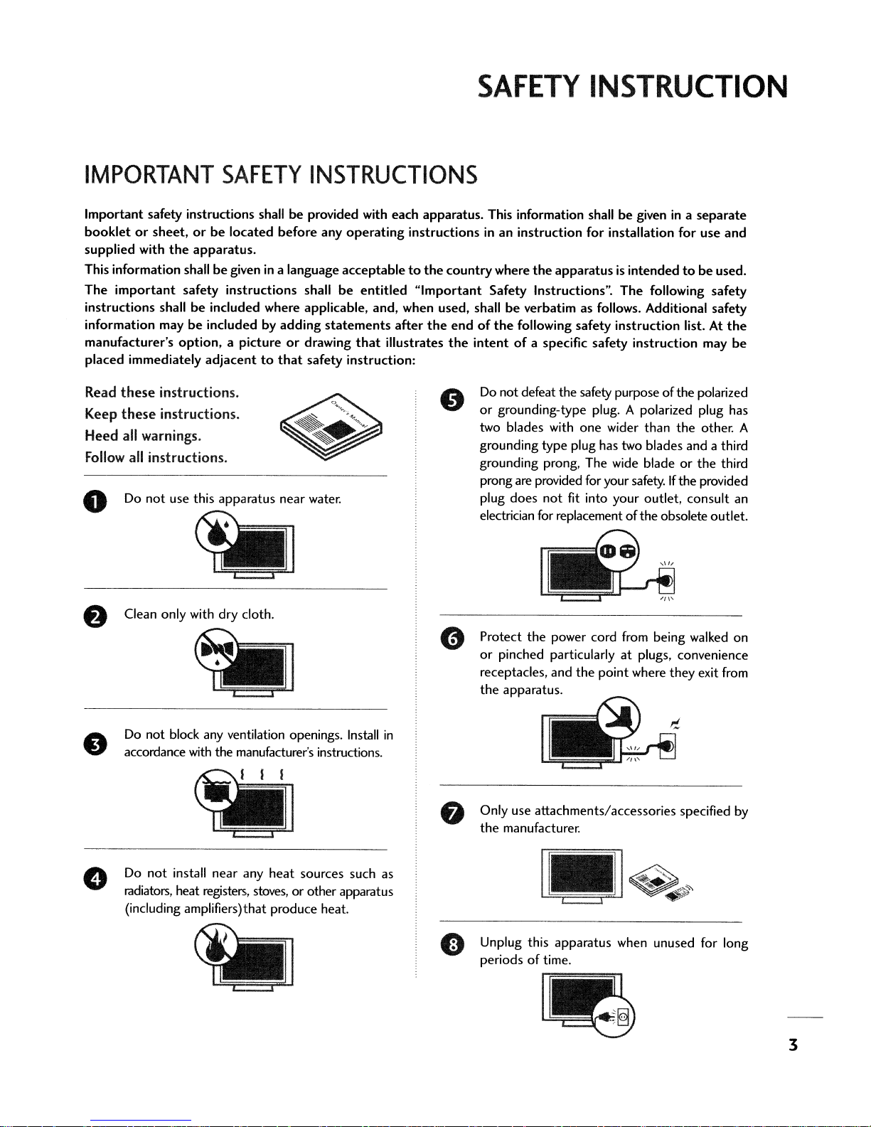
Read
these
these
Keep
Heed all warnings.
Follow
Do
o
the
option,
instructions.
instructions.
all instructions.
not
use this apparatus near water.
SAFETY
located before any
apparatus.
safety instructions shall
a pictureordrawing
adjacenttothat
INSTRUCTIONS
safety instruction:
operating
be
entitled
statements
that
instructionsinan instruction for installation for use and
"Important
after
the
illustrates
countrywhere
Safety Instructions". The following safety
endofthe
the
intentofa specific safety instruction may
Do
or
two blades with
grounding type plug has two blades and a third
grounding prong, The wide bladeorthe
prong are provided for your safety.Ifthe provided
plug does
electrician for replacement oftheobsoleteoutlet.
the
apparatusisintendedtobe
following safety instruction list. At
not defeat the safety purpose ofthe polarized
grounding-type plug. A polarized plug has
one
wider than
not
fit into your outlet, consult an
the
separate
used.
the
be
other. A
third
•
Clean only with dry cloth.
Do
not block any ventilation openings.
accordance
Do
radiators,
(including amplifiers)that produce heat.
with
the manufacturer's instructions.
not
install near any heat sources such as
heat registers,
stoves,
or other apparatus
Install
Protect
or
receptacles, and
the
in
Only use attachments/accessories specified
the
Unplug this apparatus when unused for long
periodsoftime.
the
power cord
pinched particularlyatplugs, convenience
the
apparatus.
manufacturer.
i_
1'-
I
_
!
from
being walked on
point where they exit
~
s
~
from
by
3
SAFETY
INSTRUCTION
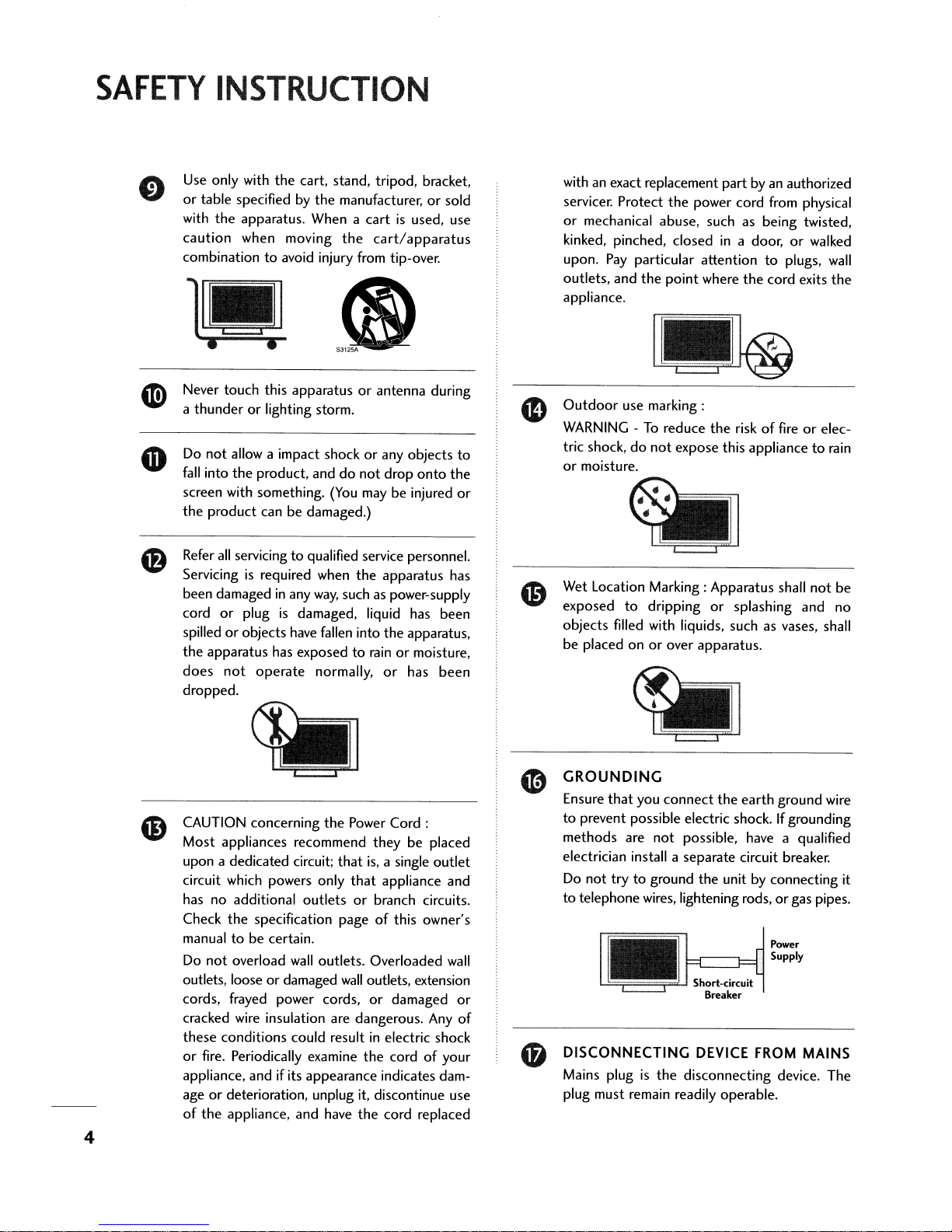
Use only with
or
table specified by
with
the
caution
combinationtoavoid injury from tip-over.
the
cart, stand, tripod, bracket,
the
manufacturer,orsold
apparatus. When a
when moving
the
cartisused, use
cart/apparatus
•
Never
touch
this
apparatusorantenna during
a
thunderorlighting storm.
Do
not
allow a impact shockorany
fall
into
the
product, anddonot
screen with something.
the
product
Refer
Servicing
been damaged
cord
spilledorobjects have fallen into
the
apparatus
does
dropped.
canbedamaged.)
all
servicingtoqualified service personnel.
is
required when
in
or
plugisdamaged, liquid has
has exposedtorainormoisture,
not
operate
any
(You
the
way,
such as power-supply
normally,
objects
drop
onto
may be injured
apparatus
the
apparatus,
or
has
the
has
been
been
to
or
with an exact replacement
servicer. Protect
or
mechanical abuse, such as being twisted,
kinked, pinched, closed
upon. Pay particular attention
outlets, and
appliance.
Outdoor
WARNING-To
tric shock,
or
moisture.
Wet Location Marking: Apparatus shall
exposed
objects
be
filled with liquids, such as vases, shall
placed onorover apparatus.
the
the
point
use marking:
reduce
do
not
expose this appliancetorain
to
dripping
part
by an authorized
power cord from physical
in
a door,orwalked
to
plugs,
where
the
cord exits
the
riskoffireorelec-
or
splashing and
not
wall
the
be
no
CAUTION concerning
Most appliances recommend
upon a dedicated circuit;
circuit which powers only
has
no
additional
Check
the
specification
manual
Do
outlets, looseordamaged
cords, frayed power cords,
cracked wire insulation are dangerous.
these
or
appliance, and
age
of
tobecertain.
not
overload
conditions could resultinelectric shock
fire. Periodically examine
or
deterioration, unplug it, discontinue use
the
appliance, and have
outletsorbranch circuits.
wall
if
its
appearance
4
the
Power
Cord:
theybeplaced
that
is,
a single
that
appliance and
pageofthis owner's
outlets. Overloaded
wall
outlets, extension
or
damaged
Any
the
cordofyour
indicates dam-
the
cord replaced
outlet
wall
or
of
GROUNDING
Ensure
that
you
connect
to
prevent possible electric shock.Ifgrounding
methods
electrician install a
Do
to
telephone wires, lightening rods,orgas pipes.
DISCONNECTING DEVICE
Mains plugisthe
plug must remain readily operable.
are
not
trytoground
•
not
the
earth
ground wire
possible, have a qualified
separate
circuit breaker.
the
unit by connecting it
Power
Supply
~Sh-ort----'circ-.lUit
Breaker
FROM
disconnecting device. The
MAINS
CONTENTS
WARNING
SAFETY
INSTRUCTIONS .
/ CAUTION...
..2
..3
PREPARATION
Accessories 6
Front
Panel
Control.
Back
Panel
Information... . .
Remote Control
Back
Cover
Attaching the TVtoa
Desktop Pedestal Installation 14
Stand Installation. . .
VESA
Wall
AntennaorCable Connection
EXTERNAL
HD Receiver
DVD
Setup . .
VCR
Setup
PC
Setup.
Key
Functions. . 10
for
Wire Arrangement
Mounting..
EQUIPMENT
Setup................................
... ...
....
Wall
. 14
SETUP
..
.
..
12
..
15
.
15
16
.17
19
20
.8
18
WATCHING TV
Turning On the TV .
Channel Selection
Volume
Channel
.7
On-Screen Menus
Adjustment........... . 22
Setup...
Selection...
.22
.22
23
24
MEDIA HOST
Entry Modes 27
Photo List 28
Music List 32
APPENDIX
Troubleshooting
Maintenance
Product Specifications
..
..
...
. 36
. .34'
.... 35
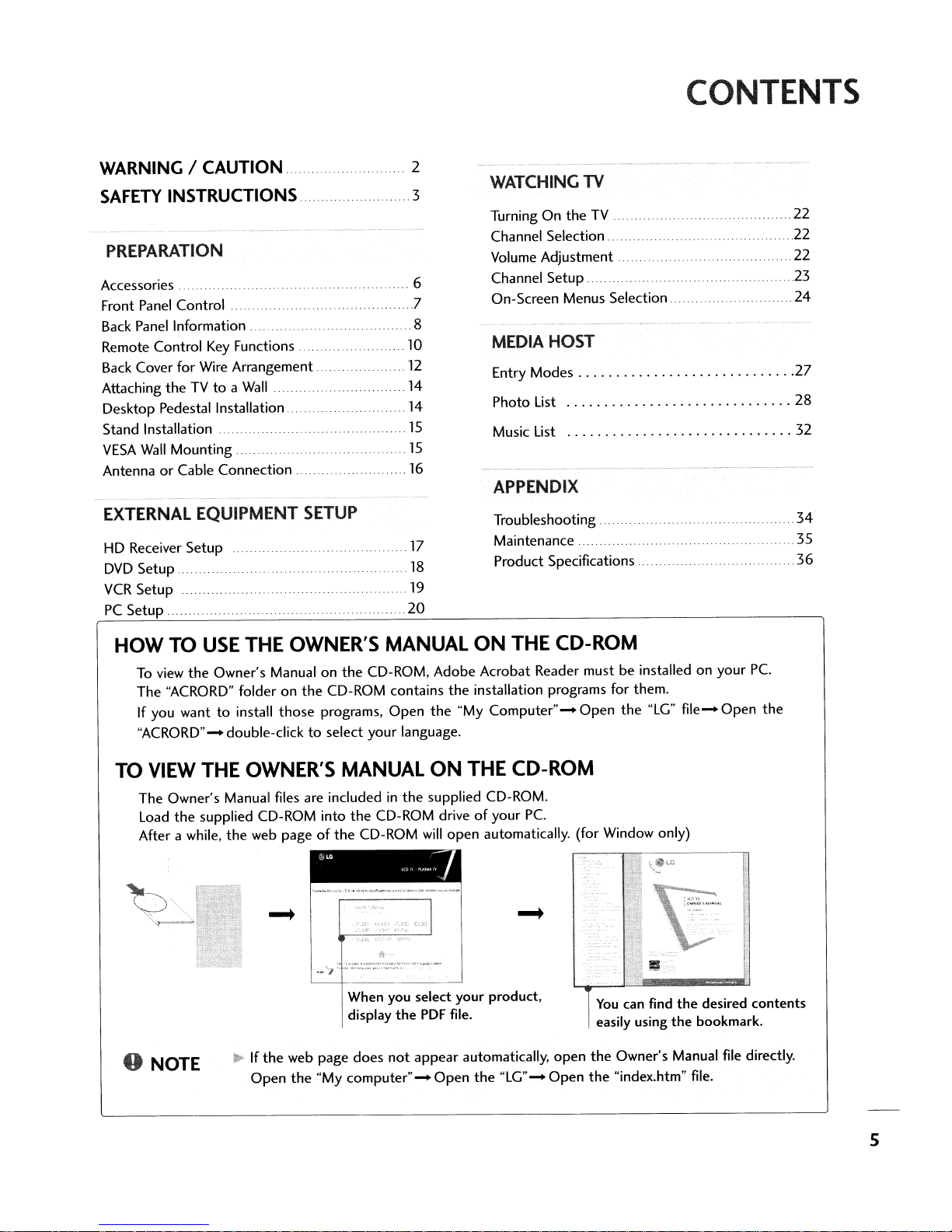
HOW
TO
o
TO
USE
THE OWNER'S MANUAL
To
view the Owner's Manual on the CD-ROM, Adobe Acrobat Reader must be installed on your Pc.
The "ACRORD" folder on the CD-ROM contains the installation programs for them.
If
you wanttoinstall those programs, Open the
"ACRORD"- double-click
to
select your language.
VIEW THE OWNER'S MANUAL
The Owner's Manual files
Load
the supplied CD-ROM
After a while, the
NOTE
web
..
Ifthe
Open the
are
includedinthe supplied CD-ROM.
into
the CD-ROM driveofyour Pc.
pageofthe CD-ROM will open automatically. (for Window only)
~
.•-'7
web page does
"My
l\
'
;;;;;::::;"::,':'::.~.,..~'
When you select your product,
display the
computer"- Open
.__•
PDF
not
appear automatically, open the Owner's Manual file directly.
ON
"My
Computer"- Open the "LG"
ON
THE CD-ROM
file.
the
"LG' - Open the "index.htm" file.
THE CD-ROM
~
You
can
easily using the bookmark.
find the desired contents
file-
Open the
5

PREPARATION
ACCESSORIES
-
Ensure
tact
User must use shielded signal interface cables (D-sub lS pin cable) with ferrite corestomaintain standard
compliance for
For
that
the
following accessories are included with your product.Ifan accessoryismissing, please con-
the
dealer where you purchased
the
product.
further information.
,
Owner's
Manual
see
the
the
product.
the
Owner's Manual files supplied CD-ROM.
o
Owner's
Manual
750hm Round Cable
CD
Manual
(Refertop.5)
Polishing Cloth
Remote Control
Batteries
• Slightly wipe stained
the
cloth for
surface
• Do
that
product exteriorifthereisstainorfingerprint on
of
the
exterior.
not
wipe roughly when removing stain. Please be cautions
excessive power
spotonthe
may
exterior only with
cause scratchordiscoloration.
Power
Cord
the
polishing
of
Option
Arrange
Extras
D-sub15pin
Twist
Holder
the
wires with
the
Cable
twist holder.
2-TVBracket Bolts
32/37
4-boIts
inches only
for
st.nd
Refer
to
assembly
p.lS·
2-TVBrackets,
2-
Wall
Brackeb
.
Cable
Management
6
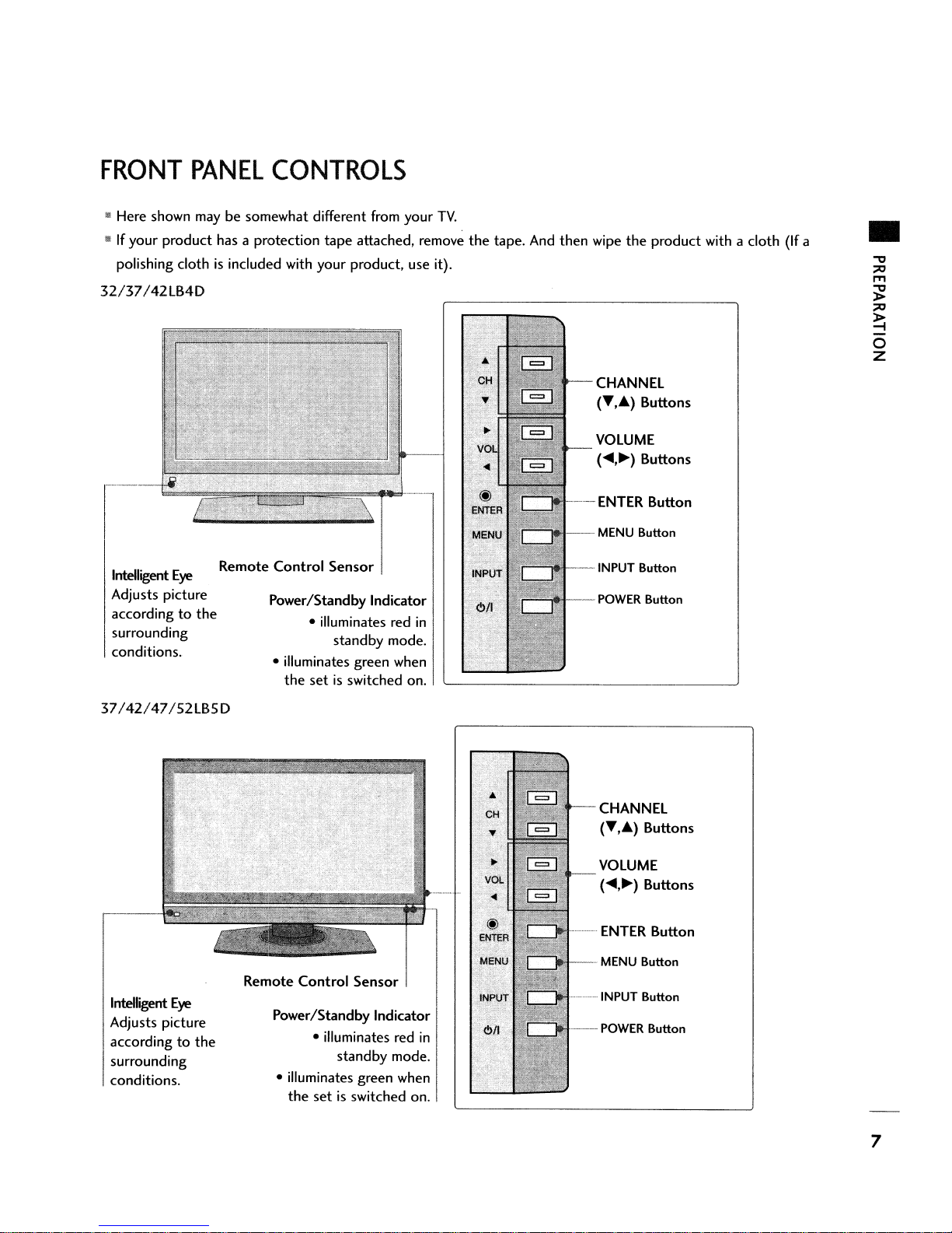
FRONT
..
Here shown
..Ifyour product
polishing cloth
32/37/42LB4D
PANEL
CONTROLS
may
be somewhat different from your
has
a protection tape attached, remove the tape. And then wipe the product with a cloth
is
included with your product,
use
TV.
it).
CHANNEL
(T••) Buttons
VOLUME
(
.....~)Buttons
----
ENTER
Button
(If
a
•
Intelligent
Adjusts picture
according
surrounding
conditions.
37/42/47/52LB5D
Intelligent
Adjusts picture
according
surrounding
conditions.
Eye
to
Eye
to
the
the
Remote
Remote
Control
Power/Standby Indicator
• illuminates green when
Power/Standby Indicator
• illuminates green when
Sensor
• illuminates red
standby mode.
the set
Control
• illuminates
the set
is
switched on.
standby mode.
is
Sensor I
red
switched on.
--MENU
--·INPUT
in
..................
in
------
Button
Button
POWER
CHANNEL
VOLUME
Button
(T,.)
Buttons
(
.....~)Buttons
ENTER
MENU Button
INPUT Button
POWER
Button
Button
7
PREPARATION
..
BACK
I~
Here
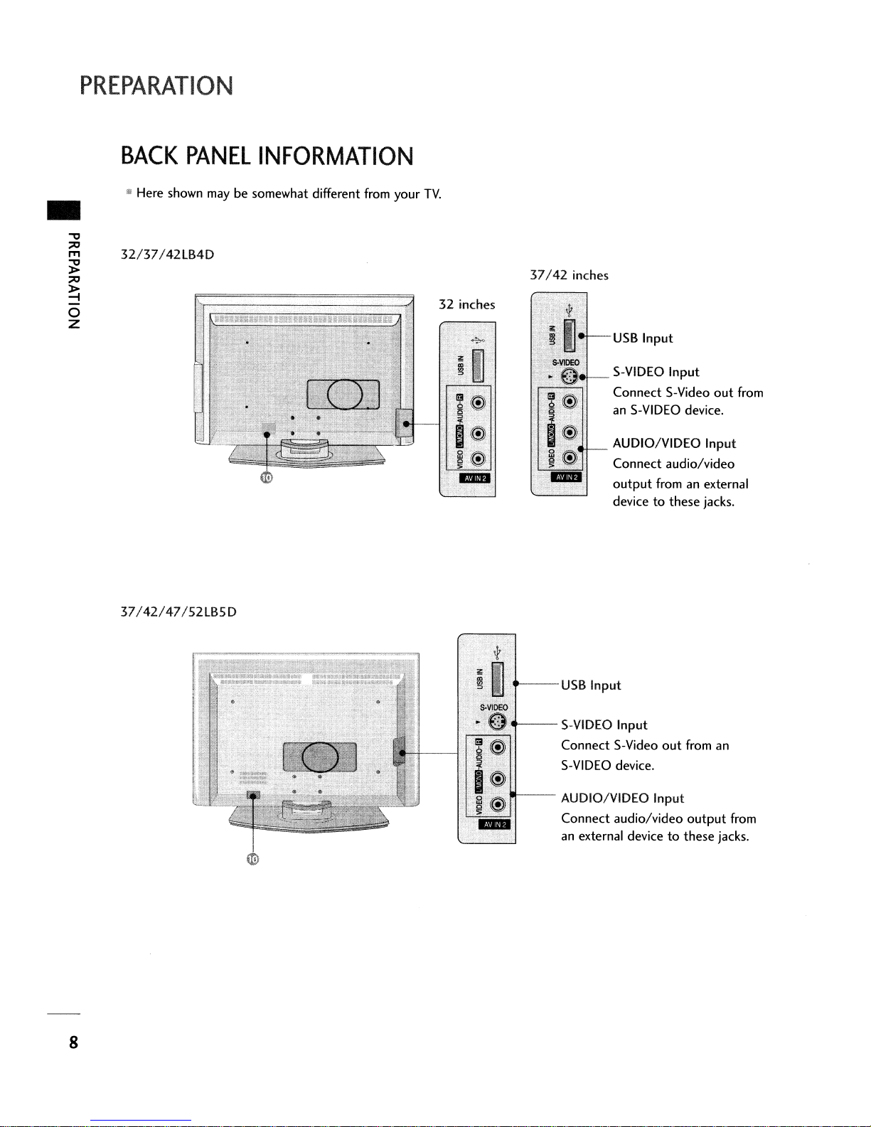
32/37/42lB4D
PANEL
shown
INFORMATION
may
be somewhat different from yourTV.
32 inches
37/42
inches
USB
S-VIDEO
Connect S-Video
an
S-VIDEO device.
AUDIO/VIDEO
Connect audio/video
output
device
Input
Input
Input
fromanexternal
to
these jacks.
out
from
37/42/47/52lB5D
----USB
--
Input
S-VIDEO
Connect S-Video
S-VIDEO device.
AUDIO/VIDEO Input
Connect audio/video
an
external devicetothese jacks.
Input
out
from
output
an
from
8
-
3
2
2
Y
@@@
o
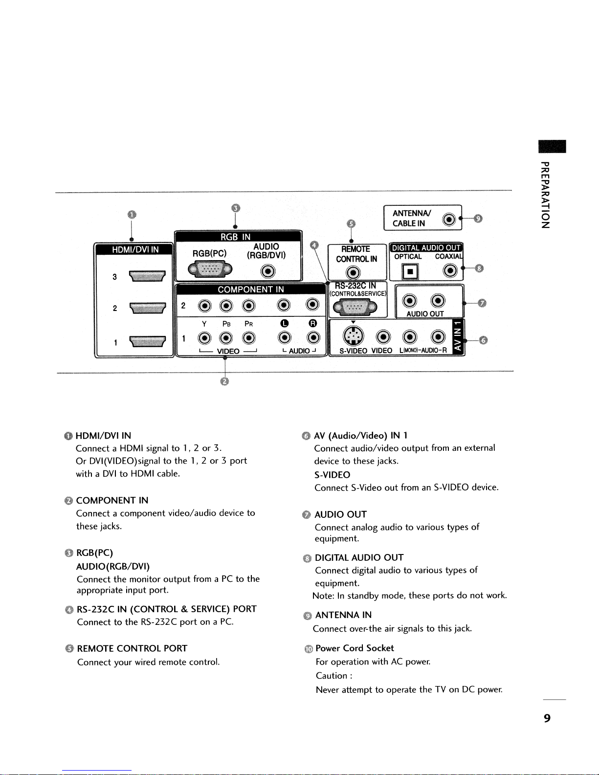
HDMI/DVI
Connect a HDMI signal
Or
DVI(VIDEO)signaltothe
with a
e
COMPONENT
Connect a component video/audio device
these jacks.
o RGB(PC)
AUDIO(RGB/DVI)
Connect the monitor
appropriate input port.
o RS-232C IN (CONTROL &
Connect
IN
DVItoHDMI cable.
IN
output
to
the RS-232C
to
1, 2or3.
port
1,2or3
SERVICE)
from aPCto
on a Pc.
PB
e
1
port
PORT
PR
to
the
L AUDIO.J
9
AV
(Audio/Video)
Connect audio/video
devicetothese jacks.
S-VIDEO
Connect S-Video
Q AUDIO
Connect analog audiotovarious types
equipment.
o DIGITAL AUDIO
Connect digital audiotovarious types
equipment.
Note:
o ANTENNA IN
Connect over-the air signals
ANTENNA!
CABLE
IN 1
output
out
fromanS-VIDEO device.
OUT
OUT
In
standby mode, these portsdonot
~
IN
@ .
fromanexternal
to
this jack.
t-e
of
of
work.
e REMOTE CONTROL PORT
your
Connect
wired remote control.
G>
Power Cord Socket
For
operation withACpower.
Caution:
Never attempttooperate the TV on DC
power.
9

PREPARATION
-
REMOTE
When using
mode
THUMBSTICK
(Up/Down/left
Right/ENTER)
the
MEDIAHOST
control
buttons
VCR/DVD
buttons
MENU
BRIGHT
+/-
EXIT
CONTROL
remote control, aim itatthe
III
Controls
• Control video cassette recorders
Displays
• Adjust brightness on screen.
•Itturnstothe
mode source.
• Navigate
settingstoyour preference.
Clear
any menu.
the
all
on-screen
FUNCTIONS
remote control
the
MEDIAHOST
main menu.
default settings brightness by changing
the
on-screen
menus and
displays and returntoTV
mode.
or
adjust
DVD
sensoronthe
players.
the
system
viewing from
TV.
......
I--
lVlNPUT
c:J
~l~j~
~MODE~
~~~
~
f-~
,......
~
J -\..
.~~
~
~
~
_~TJMER
~
-
INPUT J
I
PO$ER
]
LJ
---
~
R
EN~ERR
...
RATIO
--
...
_._---
..
r~
~
0'0
I
,
:
~
SIMPLINK
VOLUME
CHANNEL
UP/DOWN
NUMBER
- (DASH)
TIMER
RATIO
UP
/DOWN
MUTE
FAV
button
BACK
Select
the
amountoftime before yourTVturns
matically.
Change
See a list
When you toggle this button,
at
Increase/decrease
Switch
Scroll through
Select available channels.
Tunetothe
Used
program channels such as
the
to
the
aspect
ofAVdevices
screen.
the
sound onoroff.
the
last channel viewed.
enter
a program number for multiple
ratio.
connectedtoTV.
the
sound
programmed Favorite channels.
2-1,
the
SimpLink menu
level.
2-2,
etc.
off auto-
appears
~
1
I
:11.
4
I
7
I
-
I
b-
(MUTE
II
II
II
I8
!
00<>
o 0
2
5
8
0
0
~
3
II
6
~II
9
II
BACK
II
,
I
I
I
I
---.
10
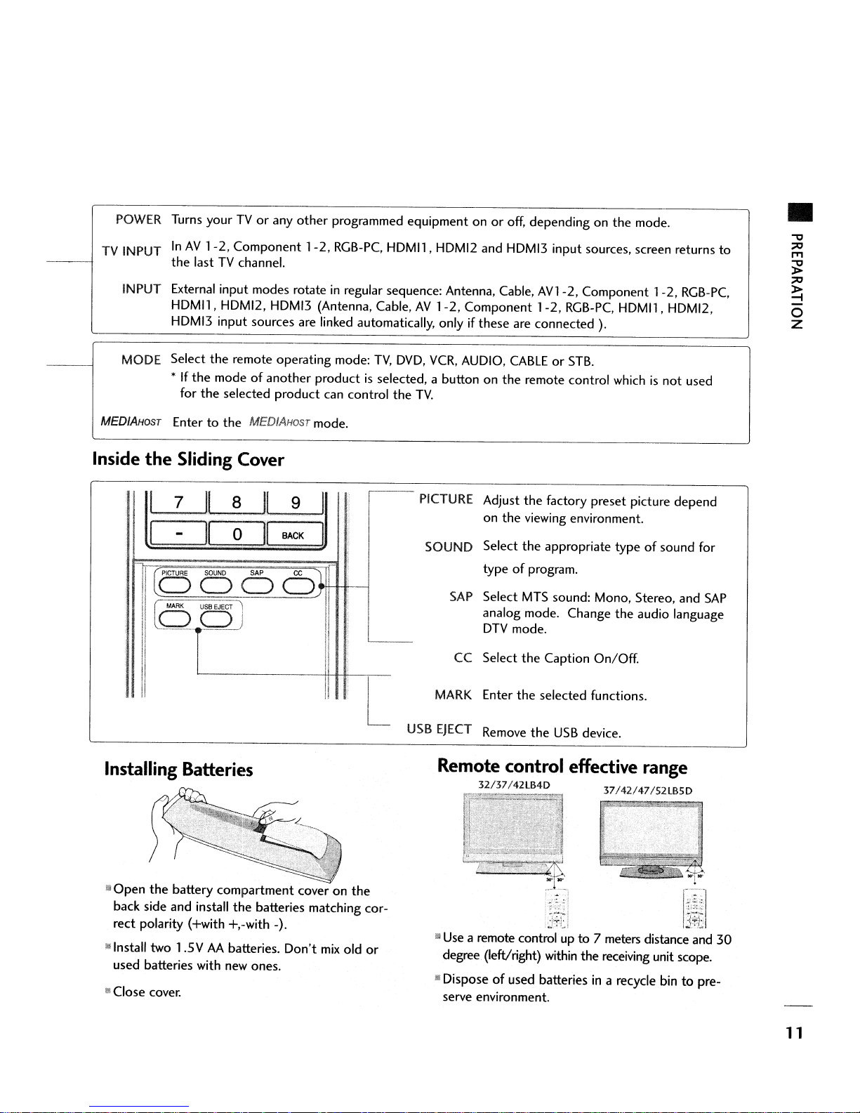
POWER
TV INPUT
Turns
yourTVor
InAV1-2,
the lastTVchannel.
any other programmed equipment onoroff, depending on the mode.
Component
1-2,
RGB-PC.
HDMl1, HDMI2
and
HDMI3 input sources,
screen
returns
•
to
INPUT External input modes rotate
HDMl1, HDMI2, HDMI3 (Antenna, Cable,AV1-2,
HDMI3 input sources
MODE Select the remote operating mode:
*
If
the modeofanother productisselected, a button on the remote control whichisnot
for
the selected product
MEDIAHOST
Inside
Entertothe
the
I
I
Sliding
7
.IL
II
..
MEDIAHOST
Cover
8
0
II
II
are
9
BACK
in
regular sequence: Antenna, Cable,
Component
linked automatically, onlyifthese
TV,
DVD,
VCR,
AUDIO,
can
mode.
I
I
..
control the
---
TV.
PICTURE Adjust the factory preset picture depend
SOUND Select the appropriate type
SAP
L
CC Select the Caption
MARK Enter the selected functions.
AVl-2,
1-2,
are
connected ).
CABLEorSTB.
on the viewing environment.
of
type
Select MTS sound: Mono, Stereo,
analog mode. Change the audio language
DTV mode.
program.
Component
RGB-PC.
On/Off.
1-2,
RGB-PC.
HDMl1, HDMI2,
used
of
sound for
and
SAP
Installing
lilOpen
back side and install the batteries matching correct polarity (+with +,-with -).
lJ Install two 1.5 V
used batteries with new ones.
II
Close
Batteries
the
battery compartment cover on the
AA
batteries.
cover.
Don't
mix
old
L
or
USB
EJECT
Remote
iJ
II
Remove
the
USB
device.
control effective
32/37/42LB4D
Use
a remote control up to 7
degree (left/right) within the receiving unit
Disposeofused batteriesina recycle bintopre-
serve
environment.
37/42/47/52LB5D
meters
range
distance
and
scope.
30
11
PREPARATION
BACK
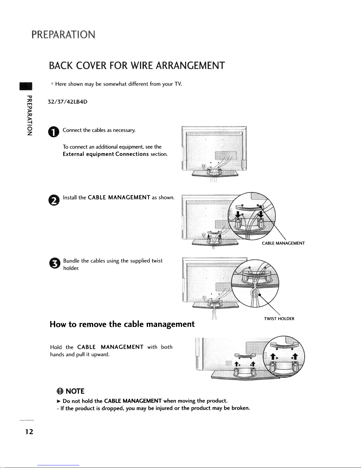
• Here shown
"
~ 32/37!42lB4D
~
~
COVER
~
~
0 Connect the cables as necessary.
To
connect an additional equipment, see the
External
f)
Install
FOR
may
be somewhat different from your
equipment
the
CABLE MANAGEMENT as shown.
WIRE
Connections
ARRANGEMENT
TV.
section.
A Bundle
~
holder.
How
Hold
hands and
the
o
NOTE
... Do
-Ifthe
to
not
the
cables using
the
supplied twist
remove the cable management
CABLE
pull
hold
productisdropped,
MANAGEMENT
it upward.
the
CABLE
with
both
MANAGEMENT when moving
you
maybeinjuredorthe
the
product
;i\\
product.
maybebroken.
TWIST HOLDER
12

• Here shown maybesomewhat different from
37/42/47/52lB5D
your
TV.
•
oConnect
To
connect an additional equipment, see
External
f)
Install
oBundle
holder.
the
cablesasnecessary.
equipment
the
CABLE
the
cables using
Connections
MANAGEMENT
the
supplied twist
the
section.
as shown.
How
Hold
hands
to
remove
the
CABLE
and
pull it upward.
the
cable management
MANAGEMENT
o NOTE
~
Do
not
hold
the
CABLE MANAGEMENT when moving
-Ifthe
productisdropped.
you
with
both
maybeinjuredorthe
the
product
product.
maybebroken.
13
PREPARATION
..
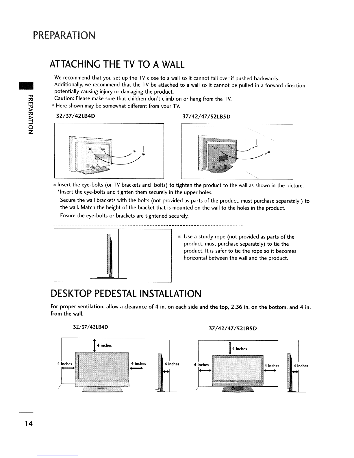
ATTACHING
We
recommend
Additionally,
potentially causing injury
Caution: Please make sure
• Here shown
32137/42
II
Insert
the
*Insert
Secure
the
wall.
Ensure
that
we
recommend
maybesomewhat different from your
LB4D
eye-bolts (orTVbrackets and bolts)totighten
the
eye-bolts and tighten them securelyinthe
the
wall
brackets with
Match
the
the
eye-boltsorbrackets are tightened securely.
THE
you
TV
TOAWALL
setuptheTVclosetoa
that
theTVbe attachedtoa
or
damaging
that
children
/
""
the
bolts (not provided as partsofthe
heightofthe
bracket
wallsoit cannot
the
product.
don't
climb onorhang from
thatismounted on
wall
so it
TV.
37/42147/52LB5D
the
producttothe
upper holes.
the
fall
overifpushed backwards .
cannot
be pulledina forward direction,
the
TV.
)
)
l
".
"
wall
as showninthe
product, must purchase separately)
walltothe holesinthe
product.
picture.
to
DESKTOP
For
proper
from
ventilation, allow a clearanceof4 in.oneach side and
the
wall.
32/37/42lB4D
-
PEDESTAL
INSTALLATION
• Use a sturdy rope (not provided as partsofthe
product, must purchase separately)totie
4 inches
product. Itissafertotie
horizontal between
the
top,
37/42147/52LB5D
the
2.36
14
the
rope so it becomes
wall
and
the
in.onthe
inches
the
product.
bottom, and 4 in.
4 inches
14

STAND
INSTALLATION
(Only
32/37
inches models)
Carefully place
o
a cushioned surface
screen from damage.
Assemble
shown.
Install
productinthe
the
product screen side down on
that
will
the
product stand with
the
4 bolts securely,inthe
holes provided.
protect product and
the
product as
backofthe
•
VESA
This
There4threaded
32lB4D
WALL
product
MOUNTING
accepts
!
200mm
a VESA-compliant
holes
are
available for attaching
o NOTE
.,..
Screw length
Wall
Mounting Instruction Guide.
needed
dependsonthe
mounting
37/42lB4D
wall
interface
the
6000101
mount used.
pad.
(optional)
bracket.
37/42147/52lB5D
For
further information, refertothe
I 37;42LB5D: 6oom01
47!52LB50:
80Qrnm
400mm
VESA
15
PREPARATION
..
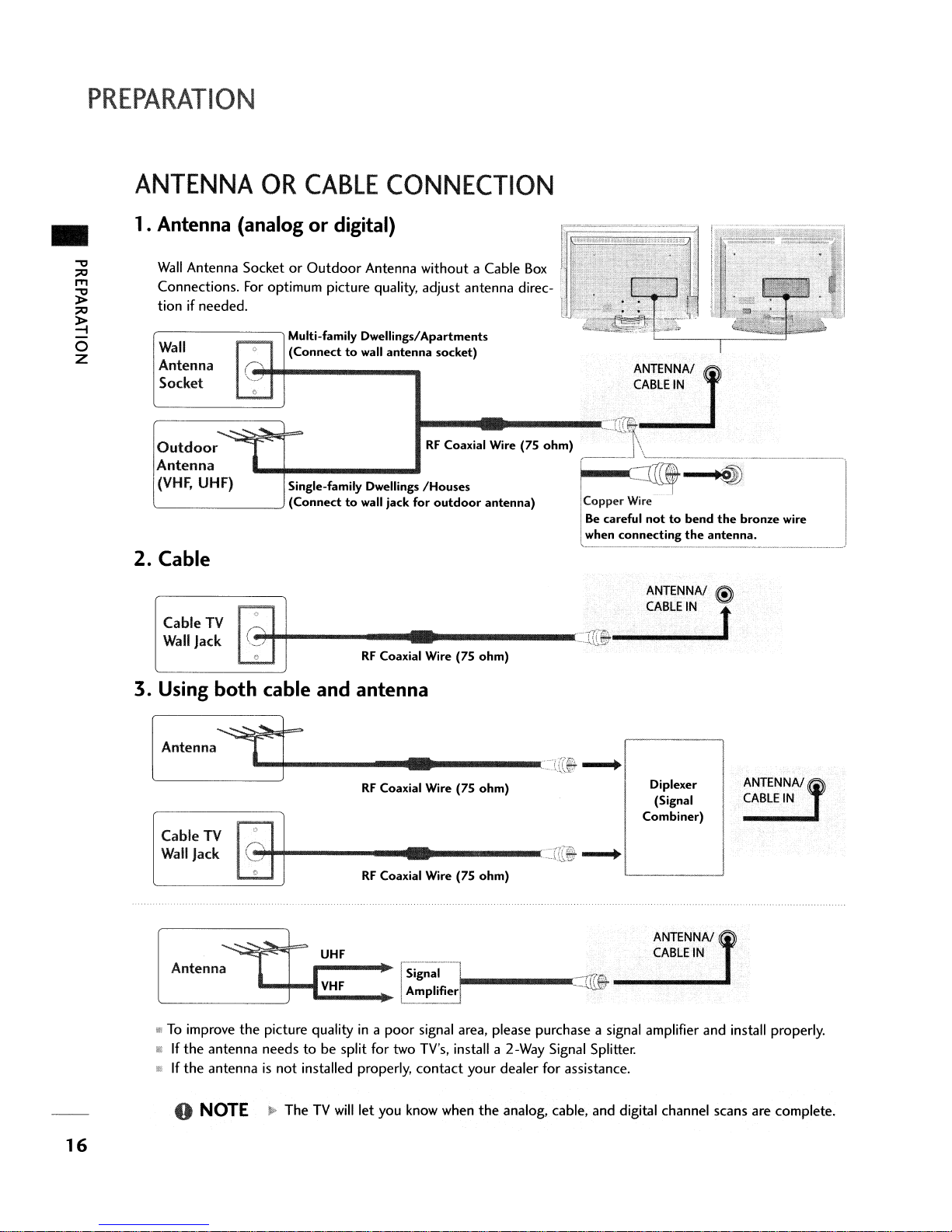
ANTENNA
OR
CABLE
1. Antenna (analogordigital)
Wall
Connections.
tion
Wall
Antenna
Socket
Outdoor
Antenna
(VHF,
'-
2.
Cable
Cable
Wall
Antenna SocketorOutdoor
For
optimum picture quality, adjust antenna direc-
if
needed.
Multi-family Dwellings/Apartments
(Connecttowall
UHF)
TV
Jack
Slngl.'''''''Y
-'
(Connecttowall jack for
_/
..,.t-+-------
Antenna without a Cable
D_lli"",
RF
Coaxial Wire (75
CONNECTION
t~"~""···,,·=-~-
Box
I]
t
f'2~~~~~~~.£i;"·
antenna
socket)
...
__
....
75
I:O:::~'·'
outdoor
...
Wi,.
1
ohm)
antenna)
---------=ITr@.
ohm)
c:CIT!l~~~~AJl
_---J
Copper
Be
when
,
~~~--,-ij)--=l
Wire
careful
nottobend
connecting
~
the
ANTENNA!
CABLE
IN
antenna.
the
@l
t
bronze
-------~
wire
3. Using
[
Anlenna
Cable
Wall
Jack
Antenna.
'--------'
III
To
improve
III
If
the
fIi\
If
the
..
both
TV
antenna
antennaisnot
NOTE
cable and antenna
5t-----..t
\)
-
C?j~+------
~
... -
1-
"'1-'CV~H~F
the
picture qualityina
needstobe split for two TV's, install a 2-Way Signal Splitter.
~
UHF
I
__
installed properly,
TheTVwill
let you know when
••
-----
RF
Coaxial Wire (75
....
------~=r[~
RF
Coaxial Wire (75
[Si;~ll
.lAmPlifier"I------==r~
poor
signal area, please purchase a signal amplifier and install properly.
contact
..
crri--.
ohm)
Diplexer
(Signal
Comhln~)
ANT.ENNA/f
CABLE
I
--.
ohm)
ANTENNA!
CABLEtN
your dealer for assistance.
the
analog, cable, and digital channel scans are complete.
IN
16
EXTERNAL
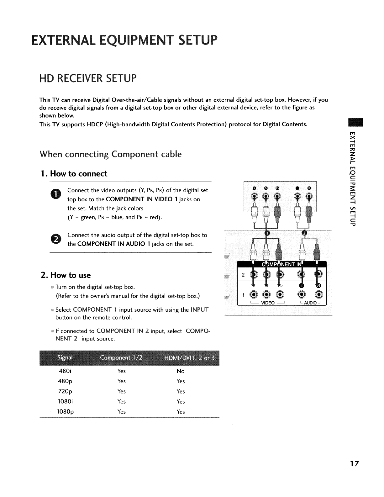
HD
RECEIVER
EQUIPMENT
SETUP
SETUP
ThisTVcan receive Digital Over-the-air/Cable signals without an external digital
do
receive digital signals from a digital
shown below.
ThisTVsupports
When connecting
1. How
Connect
o
top
the
(Y
Connect
the
2.
Howtouse
HDCP (High-bandwidth Digital
Component
to
connect
the
video
outputs
boxtothe
set. Match
= green,PB= blue, andPR= red).
COMPONENTINAUDIO 1 jacks on
COMPONENTINVIDEO
the
jack colors
the
audio
outputofthe
set-top
boxorother
cable
(Y,
PB,
PR)
digital set-top box
Contents
of
the
1 jacks on
the
digital external device, refertothe
Protection) protocol for Digital Contents.
digital
set
to
set.
set-top
o
~ ~
'"
box. However, if you
figure as
G G
"
..
IT'I
X
-4
IT'I
:;lO
Z
»
r
IT'I
I:)
C
"'tI
~
IT'I
Z
-4
VI
IT'I
-4
C
"'tI
it
Turnonthe
(Refertothe
mSelect COMPONENT 1 input source with using
button on
'!\!
If
connectedtoCOMPONENTIN2 input, select COMPO-
NENT 2 input source.
Signal Component
480i
480p
nop
1080i
lO80p
digital set-top box.
owner's manual for
the
remote control.
Yes
Yes
Yes
Yes
Yes
the
digital set-top box.)
122
the
H£iMI2£iVI1',2or
No
Yes
Yes
Yes
Yes
INPUT
:3
L.-
VIDEO
---'
LAUDIO.J
17

EXTERNAL
EQUIPMENT
SETUP
..
I'T1
X
-l
l'Tl
;;:0
Z
>
r-
I'T1
o
C
-0
~
I'T1
Z
-l
VI
I'T1
-l
C
-0
DVD
SETUP
When connecting Component cable
1. How
2. How
to
connect
Connect
o
the
Match
(Y
Connect
COMPONENT
to
" Turnonthe
1M
Select COMPONENT 1 input source with using
INPUT
II
If
connectedtoCOMPONENTIN2 input,
PONENT 2 input source.
the
video
outputs
COMPONENT
the
jack colors
= green,PB= blue, andPR= red).
the
audio
outputsofthe
IN
IN
VIDEOl
AUDIOl
(Y,
PB,
jacksonthe
use
DVD
player, insert a
buttononthe
remote control.
DVD.
PR)ofthe
jacksonthe
DVDtothe
select
DVD
set.
the
COM-
set.
to
'--
VIDEO
---'
L AUDIO-'
III Refer
tions.
to
the
DVD
player's manual for operating instruc-
When connecting HDMI cable
1. How
2. How
to
connect
o
Connect
HDMI/OVI
the
HDMI
outputofthe
IN1,2or
3 jack on
8 No separated audio connection
to
use
ll'l Select HOMI1, HOMI2
the
INPUT button on
!III
Refertothe
tions.
III
If
the
the
output
DVD
DVD
does
resolution appropriately.
or
HDMI3 input source with using
the
remote control.
player's manual for operating instruc-
not
support
Auto
is
HDMI,
DVDtothe
the
set.
necessary.
you needtoset
HDMIIDVIIN
3 Wiiii1
HOIIl-OVO
OUTPUT
IN
nGB{PC)
COMPO
18

VCR
SETUP
When
1•
2.
connecting
Howtoconnect
Connect
o
VCR.
white,and Audio Right =
How
to
use
III Insert a video
VCR.
(Refertothe
mSelect
•
AVl
the
remote control.
If
connectedtoAV IN2,select AV2 input source.
with a
the
AUDIO/VIDEO jacks betweenTVand
Match
the
jack colors(Video = yellow, Audio Left =
red}
tape
into
the
VCR
VCR
owner's manual.)
input source with using
RCA
and press
the
cable
PLAYonthe
INPUT
button
on
VIDEO
•
.
O~@@
S-VIDEO VIDEO
o NOTE
~
If
you have a mono
nect
VCRtothe
L/
LllIONOl-AUllIO-R
the
audio cable from
M0 N0 jackofthe
..
AUDIO
5-V1DEO
~
OUTPUT
SWITCH
VCR.
~,
con-
set.
the
ANT
ANT
e
@
OUT
IN
..
I'T'l
X
-i
I'T'l
;;0
Z
>
r-
I'T'l
I:)
C
"'tl
~
I'T'l
Z
-i
V\
I'T'l
-i
C
"'tl
When
1•
2.
connecting
Howtoconnect
Connect
o
VIDEO
improved; comparedtonormal composite
input.
Connect
input jacks
Howtouse
@ Insert a video
(Refertothe
lil
Select AVl input source with using
remote control.
iii
If
connectedtoAVIN2, select AV2 input source.
the
S-VIDEO
input
the
audio
on
the
tape
into
VCR
owner's manual.)
with an S-Video
outputofthe
on
the
set.
The
picture
outputsofthe
set.
the
VCR
VCRtothe
and press
the
PLAYonthe
INPUT buttononthe
cable
VCRtothe
quality
(RCA
cable)
AUDIO
S-
is
VCR.
S-VIOEO
VIDEO.
@
.••
o@
S-VIDEO VIDEO
A CAUTION
... Do
not
connecttoboth
and S-Video
at
4)
the
same time.
ANT
IN
Video
19
EXTERNAL
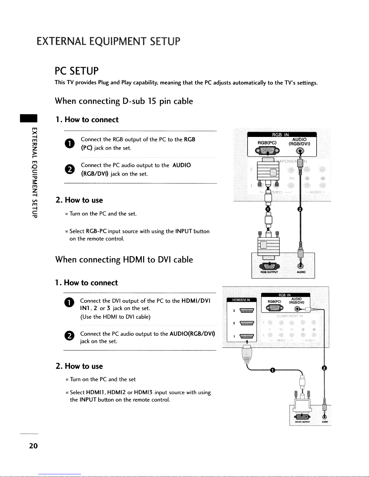
PC
SETUP
ThisTVprovides Plug
EQUIPMENT
and
Play capability, meaning
SETUP
that
thePCadjusts
automaticallytothe
TV's settings.
..
m
><
-i
m
:::0
Z
>
r0-
m
o
C
"'tl
3:
m
Z
-l
V\
m
-i
C
"
When connecting D-sub
1• Howtoconnect
Connect
o
(PC) jackonthe
Connect
(RGB/DVI) jack
2.
Howtouse
mTurn on
Iii Select RGB-PC input source with using
on
the
the
RGB
thePCaudio
thePCand
remote control.
the
outputofthePCto
set.
outputtothe
on
the
set.
set.
When connecting HDMI
15
pin cable
to
DVI
the
RGB
AUDIO
the
INPUT button
cable
RGB
IN
AUDIO
(RGB/DVI)
20
1• Howtoconnect
o
Connect
IN1,2or
(Use
Connect
jack
the
the
HDMItoDVI
thePCaudio
on
the
DVI
3 jackonthe
set.
2. Howtouse
til!
TurnonthePCand
!II Select
HDMIl,
the
INPUT buttononthe
HDMI2orHDMI3 input source with using
outputofthePCto
set.
cable)
outputtothe
the
set
remote control.
the
HDMI/DVI
AUDIO(RGB/DVI)
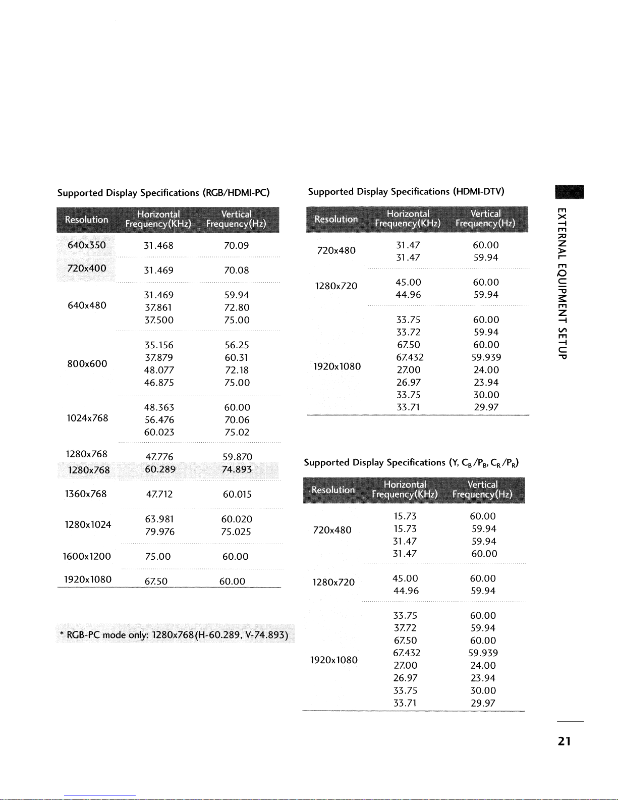
Supported
I
Reso utlon
640x480
800x600
1024x768
Display Specifications (RGB/HDMI-PC)
.
Horizontal Vertical
Frequency(~Hz)
31.468 70.09
31.469 70.08
31.469
3Z861
3Z500
35.156 56.25
3Z879 60.31
48.077
46.875
48.363
56.476 70.06
60.023
Frequency(Hz)
59.94
72.80
75.00
72.18
75.00
60.00
75.02
Supported
72Ox480
1280x720
1920x1080
Display Specifications
31.47
31.47
45.00
44.96
33.75
33.72
6Z50
6Z432
2Z00
26.97
33.75
33.71 29.97
(HDMI-DTV)
60.00
59.94
60.00
59.94
60.00
59.94
60.00
59.939
24.00
23.94
30.00
..
IT'I
X
-i
IT'I
:;:0
Z
>
~
IT'I
o
C
-0
~
IT'I
Z
-i
VI
IT'I
-i
C
-0
1280x768
1280x768
1360x768
1280x1024
1600x1200
1920x1080
4Z776 59.870
4Z712 60.015
63.981
79.976 75.025
75.00
6Z50
60.020
60.00
60.00
72Ox480
1280x720
1920x1080
15.73
15.73
31.47
31.47
45.00
44.96
33.75
3Z72
6Z50
6Z432 59.939
2Z00
26.97
33.75
33.71
60.00
59.94
59.94
60.00
60.00
59.94
......."....
60.00
59.94
60.00
24.00
23.94
30.00
29.97
21

WATCHING
TV
-
TURNING
First,
connect
o
At
this moment,
a
In
standby mode, press
button on theTVor
Number
the
Select
trol.
It
ThisTVis
even
if
When finished using the
control.
The
o NOTE
...Ifyo.u
ill-
When
intendtobe
theTVis
ON
TV
power cord correctly.
theTVswitchestostandby mode.
the
6/1
(or ON/OFF), INPUT, CH (...
press the
(0-9)
buttononthe
viewing source by using
programmedtoremember which mode it
you turn
theTVoff.
TV
revertstostandby mode.
awayonvacation, disconnect
turned
on,
TV,
POWER,
remote control.
the
press
the
the
indicator
INPUT,TVINPUT,
INPUT buttononthe
POWER button on
will
was
the
the
power plug from
blink red before
CH('"
remote con-
last
set
remote
the
pictureisseen.
or
or
to,
T)
T),
the
wall
power outlet.
CHANNEL
o Press
the
CH ...
VOLUME
Adjust
the
volumetosuit
o Press
f)
e
the
VOL
If
you wanttoswitch
You
can cancel
button.
SELECTION
orTor
NUMBER buttonstoselect a channel number.
ADJUSTMENT
your
personal preference.
...
or
T button
the
the
Mute functionbypressing
sound
to
adjust
off,
press
the
volume.
the
MUTE button.
the
MUTEorVOL
.....
~RI~T~
88
~
1
•
.0
4
7
•8•
-
I
'r~~'x'(k,'[
1 H 2 " 3
4U'5 U 6
...
or
T
I718T9l
I
2
5
0
~
3
•
s
D.
9
"""
•
,
22

CHANNEL
SETUP
Auto Scan(Auto Tuning)
C)
1'/
INPUT
~;;-J
~
C)
INPUT
Automatically finds all channels available
cable inputs, and
Run
Auto Tuning again
changes.
A passwordisrequiredtogain accesstoAuto Tuning menu if
the
Lock Systemisturned
Press
o
tontoselect
Press
select Auto
Press
search.
search cycle for ANTENNA and
stores
theminmemoryonthe
after
any
Antenna/Cable
on.
the
MENU
the~button and then
the
ENTER
Allow
button and then
the
SETUP menu.
Tunins
buttontobegin
Auto
Tuningtocomplete
through
use'"orT but-
use'"
or
the
channel
CABLE.
antenna
channel list.
connection
T button
the
channel
or
to
-
o NOTE
AnalogTVantenna
Digital
DTV
antenna
Analog
Digital
CATV
CADTV
cable
cable
23
WATCHING
TV
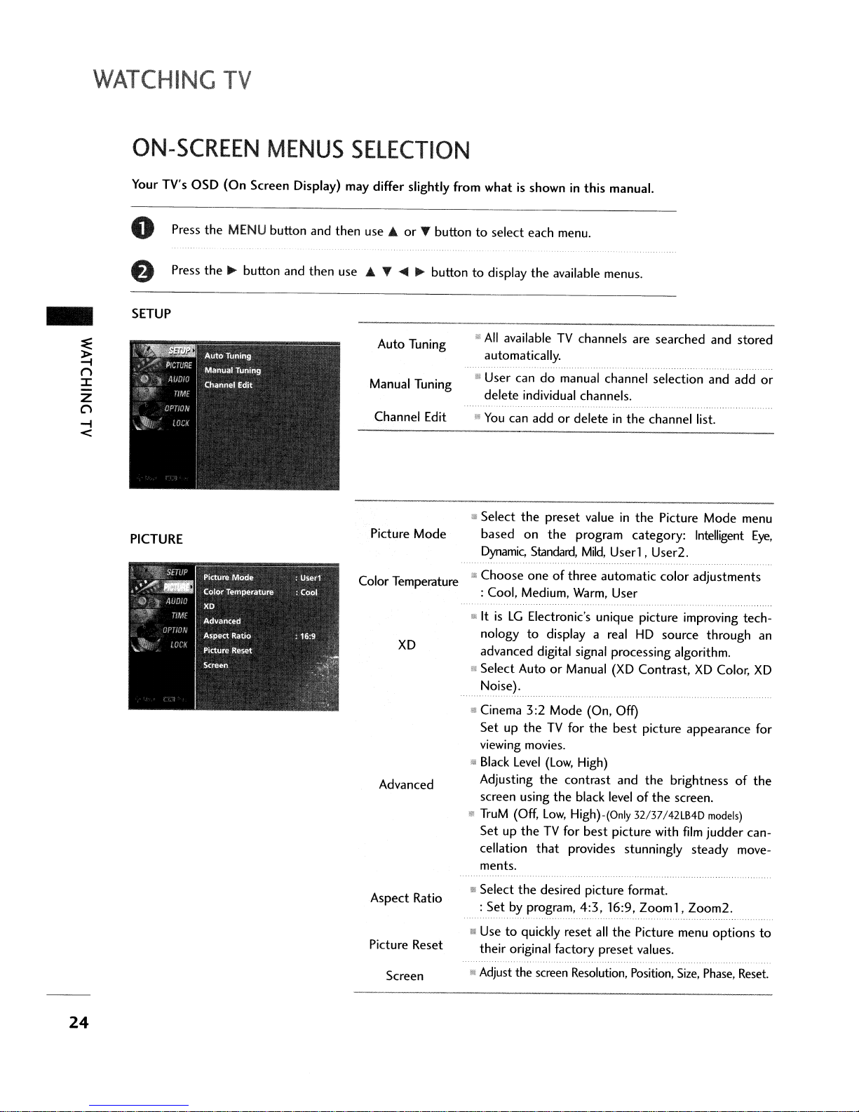
ON-SCREEN
Your TV's
o Press
8 Press
SETUP
PICTURE
OSD
(On
the
MENU
the~button
Screen
MENUS
Display) may differ slightly from
button
and
then
SELECTION
and
then
use ...
use ... T
Auto Tuning
Manual Tuning
Channel Edit
Picture
Color Temperature
orTbuttontoselect
....
~
buttontodisplay
• User
iii
$
Mode
f!.>
whatisshowninthis
each
menu.
the
available menus.
All
availableTVchannels are
automatically.
candomanual channel selection
delete
individual channels.
You
can
addordeleteinthe
Select
the
preset
based
Choose
: Cool, Medium, Warm, User
Dynamic,
on
the
Standard,
oneofthree
manual.
valueinthe
program
Mild,
Userl,
automatic
searched
channel list.
Picture
category:
User2.
color
and
stored
and
add
Mode
menu
Intelligent
adjustments
or
Eye,
XD
Advanced
Aspect
Picture Reset
Ratio
Screen
'"ItisLGElectronic's unique picture improving
nologytodisplay a real
advanced digital signal processing algorithm.
Wi
Select
AutoorManual
Noise).
g Cinema
SetuptheTVfor
viewing movies.
ill
Black
Adjusting
screen using
li!
TruM
SetuptheTVfor
cellation
ments.
!111
Select
:
!II Use
their original factory
iii
Adjust the screen Resolution, Position,
Level
(Off,
the
Set
by program,
to
3:2
Mode
(On, Off)
the
(Low,
High)
the
contrast
the
black levelofthe
Low,
High)-(Only 32/37/42LB4D
best
that
provides stunningly
desired picture format.
4:3,16:9,
quickly
reset
HD
(XD
best
and
picture with
all
the
preset
source
Contrast,
picture
the
Zoom1,
Picture menu
values.
XD
appearance
brightnessofthe
screen.
film
steady
Zoom2.
Size,
through
Color,
models)
judder
options
Phase, Reset.
tech-
an
XD
for
can-
move-
to
24

AUDIO
Sound Mode
!II Sound Mode lets you enjoy
out
any special adjustment.
: Standard, Music, Movie,
the
Sports
best
sound
and User
with-
TIME
Auto Volume
Balance
TV
Speaker
Clock
Off
Time
On
Time
III Scans for changes
then
cials,
adjusts
in
sound
the
soundtomatch
levels during commer-
audio level.
III Adjust
.. Turn
..
Auto: The timeisset
the
left/right soundofspeaker.
theTVspeakerOnor
automatically from a digital
off.
channel signal.
Select your viewing area time zone.
Select Auto, Off,
not
your viewing area observes Daylight Saving
On
depending
time.
• Manual:
• Select
III Select
Set
the
OnorOff.
OnorOff.
clock manually.
on
the
specified
whether
or
Sleep Time
Auto Sleep
III
Select
the
amountoftime before yourTVturns off
automatically: Off, 10,
240
.
.,
TV
will
be automatically turned
Signal for10minutes.
20,30,
60,
90,
120, 180,
off,incaseofNo
25

WATCHING
TV
-
~
()
~
z
C)
-I
<
OPTION
Language
Input Label
SimpLink
key
Lock
Caption
SetlD
III Select your desired language for
: English, Spanish, French.
IiiI
Set
a labeltoeach input source.
ill
Control and play
TV
through
and settings.
III This feature can be used
viewing by locking
II
Mode: When selecting Off, Submenus for Analog,
DTV,
and Digital
III Analog:
ill Digital: Service1 - Service6
III
Digital Option: Customize
tions
II!
Choose
CC1-
that
the
otherAVdevices
HDMI
cable without additional cables
out
the
Option
CC4,Textl-
appearonyour screen.
desiredTVID
become
on
screen menus
connectedtothe
to
prevent unauthorized
front panel controls.
disabled.
Text4·
the
DTV
/CADTV cap-
number.
26
LOCK
For
For
Canada
USA
Lock
System
Set
Password
Block Channel
Movie Rating
TV
Rating-Children
TV
Rating-General
TV
Rating-English
TV
Rating-French
input
Block
III Select
II
ill
III Blocks movies according
1Il
iii
III Selecting canadian english language rating system.
Il
• Enables you
OnorOff.
Change
Select a channel number
specified.
Prevents children from watching certain children's
TV
Basedonthe
that
Selecting canadian french language rating system .
external source devices you have hooked up.
the
password.
that
to
the
programs, accordingtothe
ratings, blocks certain
you
and
your familydonot
to
select a sourcetoblock from
you wishtoblock.
movie ratings limits
ratings limit set.
TV
programs
wanttoview.
the
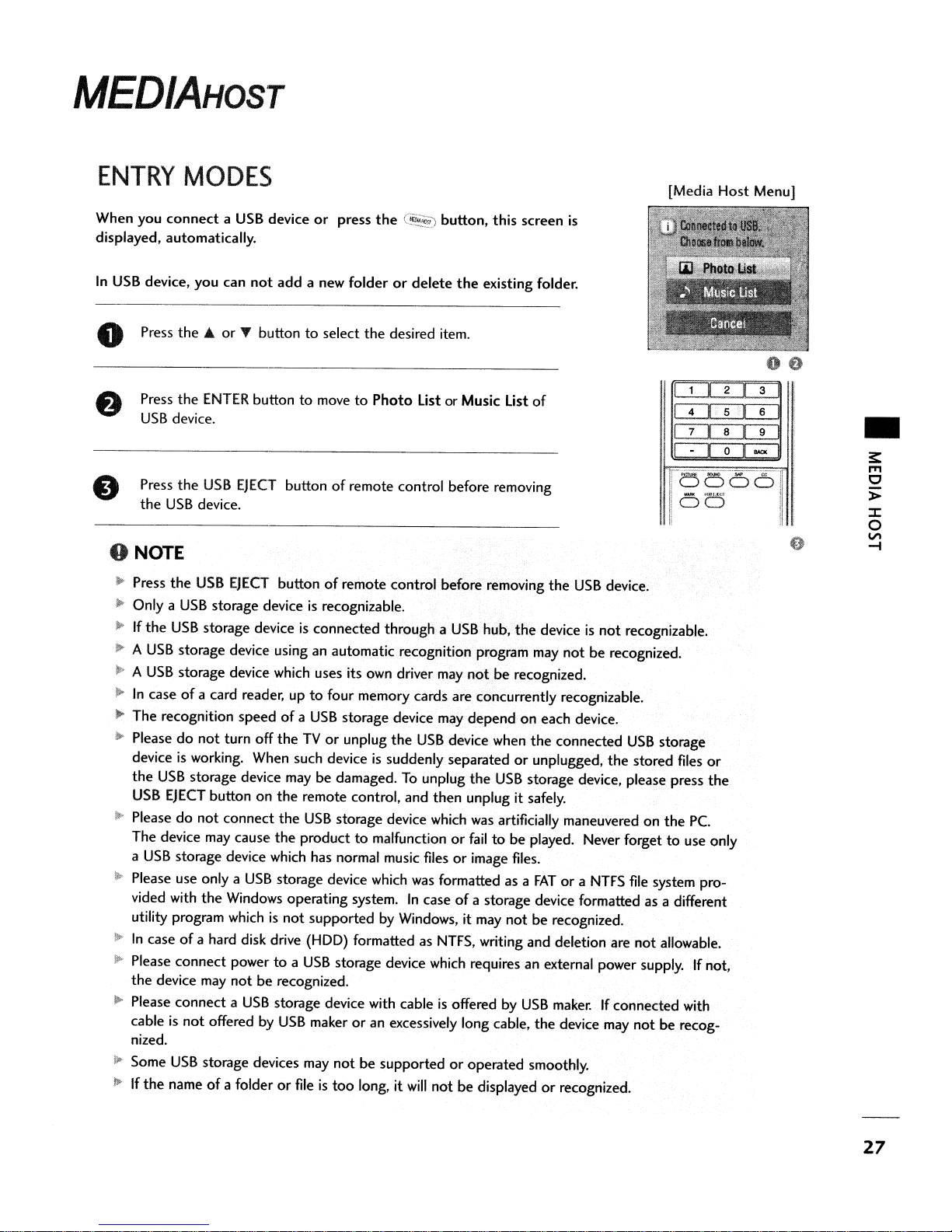
MEDIAHOST
ENTRY
When you
displayed, automatically.
In
USB
o Press
MODES
connectaUSB
device, you can
the'"
or
Press
the
ENTER
USB
device.
Press
the
USB
the
USB
device.
deviceorpress
not
add
a new folderordelete
" buttontoselect
buttontomovetoPhoto
EJECT
buttonofremote control before removing
the
the
(§..~
desired item.
List or Music List
button, this screen
the
existing folder.
o NOTE
'~
Press
the
USB
EJECT
J>
Only a
)I>
~
A
~
A
~
The recognition
ill-
deviceisworking. When such deviceissuddenly separatedorunplugged,
:--
~
Iii'
II>
I>
110
110
USB
storage deviceisrecognizable.
If
the
USB
storage deviceisconnected through a
USB
storage device using an automatic recognition program may
USB
storage device which uses its own driver may
In
caseofa card reader, uptofour memory cards are concurrently recognizable.
Pleasedonot
the
USB
USB
EJECT
Pleasedonot
The device
a
USB
storage device which has normal music filesorimage files.
Please use only a
vided with
utility program whichisnot
In
caseofa hard disk drive (HOD) formatted as
Please connect powertoa
the
device may
Please connect a
cableisnot
nized.
Some
USB
If
the
nameofa folderorfileistoo
turn off
storage device may be damaged.Tounplug
button on
connect
may
the
Windows operating system.Incaseofa storage device formatted as a different
offeredbyUSB
storage devices may
buttonofremote control before removing
speedofa
cause
USB
not
be recognized.
USB
USB
storage device may
theTVor
the
the
the
storage device which
storage device with cableisoffered by
unplug
the
USB
remote control, and
USB
storage device which was artificially maneuvered on
producttomalfunctionorfailtobe
supported by Windows, it
USB
storage device which requires an external power supply.Ifnot,
makeroran excessively long cable,
not
be supportedoroperated smoothly.
long, it
then
was
formatted as a
NTFS,
will
notbedisplayedorrecognized.
USB
hub,
not
be recognized.
depend
device when
the
USB
unplug it safely.
may
notberecognized.
writing and deletion are
[Media Host Menu]
is
of
1~1~D:::=2=~"3=J
4 I
1
•
r-<5<:5'66.01
:
IiWIII
i
DD
the
USB
device.
the
deviceisnot
not
on each device.
the
connected
storage device, please press
played. Never forgettouse only
FATora
USB
maker.Ifconnected with
the
device may
recognizable.
be recognized.
USB
storage
the
stored files
the
NTFS
file
system pro-
not
allowable.
not
be recog-
Pc.
00
51
6
Dol
,;,;eh.t.Cl I
"""
or
the
•
I
!
27

MEDIAHOST
PHOTO
It's availabletoplayback
device.
The On Screen Display may be different from your set. Images
are an example
Screen Components
-
~
I'T1
o
> 0 Usable
::I:
o
VI
-I
LIST
the
photo
to
assist with
USB
memory
theTVoperation.
e Current page/Total pages
of
Total number
thumbnail photos
o Corresponding buttons
on the remote control
marked
file(*.jpg)inthe
USB
28
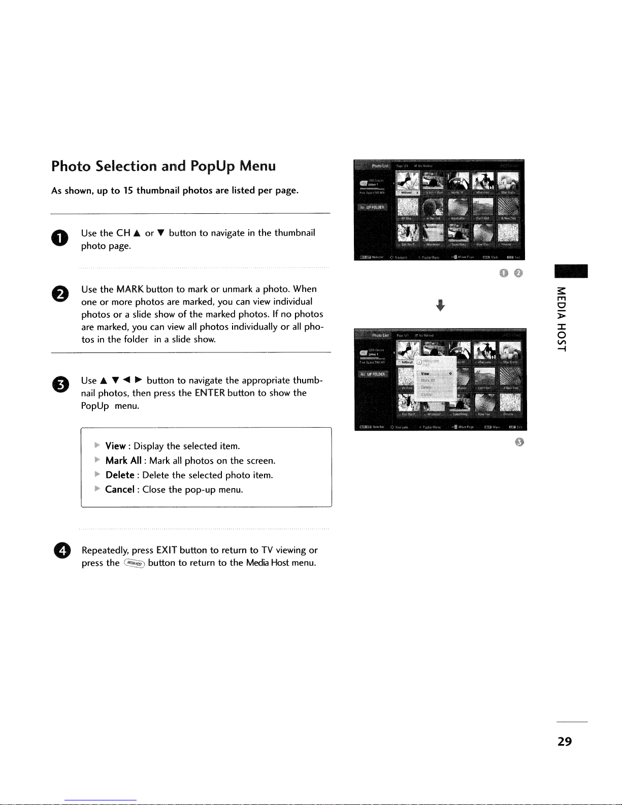
Photo Selection and PopUp Menu
As
shown, up
o
tolSthumbnail
Use
the
CH ...orT buttontonavigateinthe
photo
page.
the
MARK
Use
oneormore
photosora slide showofthe
are marked, you can
tosinthe
Use'"
T
nail
photos,
PopUp menu.
~
View: Display
~
Mark
ll-
Delete:
10
Cancel:
buttontomarkorunmark a photo. When
photos
folderina slide show.
....
~
buttontonavigate
then
All
: Mark
Delete
Close
photos
are marked, you can
view
all
press
the
the
selected item.
all
photosonthe
the
selected
the
pop-up
are
listed
per
view
marked photos.Ifno
photos
ENTER
individuallyorall
the
appropriate thumb-
buttontoshow
screen.
photo
item.
menu.
page.
thumbnail
individual
photos
pho-
the
-
~
I'Tl
o
»
::J:
o
VI
-i
Repeatedly, press
press
the
C~
EXIT
buttontoreturntoTV
buttontoreturntothe
Media
viewing
Host menu.
or
29
MEDIAHOST
-
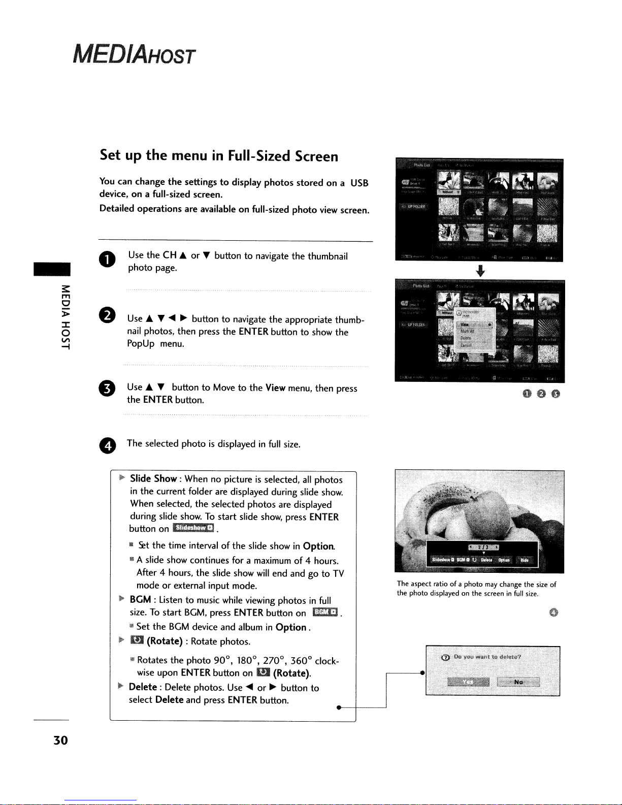
Set up
You
device,ona full-sized screen.
Detailed
o
8
e The selected photo
the
can
change
operations
Use
theCH..
photo
page.
Use"
nail
photos. then press
PopUp menu.
Use'"
the
ENTER
menu
the
settingstodisplay
are
availableonfull-sized
or
T
~
~
buttontonavigate
T button
button.
in
T button
to
is
Full-Sized Screen
photos
to
navigate
the
ENTER buttontoshow
Movetothe
displayedinfull
storedona
photo
the
the
appropriate thumb-
View menu, then press
size.
view
thumbnail
the
USB
screen.
oeo
30
Il>
Slide
Show:
When no pictureisselected,
in
the
current folder are displayed during slide
When selected,
during slide
button
on
III
~t
the
III A slide show continues for a maximum
After 4 hours,
modeorexternal input mode.
~
BGM: Listentomusic while viewing
size.Tostart
lil
Set
the
...
m
(Rotate)
III
Rotates
wise upon
l!'
Delete:
select
Delete
the
selected
show.Tostart
litdCje·l.
time intervalofthe
the
slide show
BGM,
press
BGM
device and albuminOption
: Rotate photos.
the
photo
90
ENTER
Delete photos. Use~or~button
button
and press ENTER button.
photos
slide show, press
slide showinOption.
will
ENTER
0
0
I
,
180
on
OJ
all
photos
show.
are displayed
ENTER
of
4 hours.
end andgoto
photosinfull
button on 1iIltm].
.
0
,
270
3600clock-
(Rotate).
to
TV
The aspect ratio of a photo
the photo displayed on the screen
may
change the size of
in
full
size.
 Loading...