

LG 42PX3RV, 42PX3RVB, 42PX3RV-ZA, 42PX3RVB-ZA Service Manual

PLASMA TV
SERVICE MANUAL
CAUTION
BEFORE SERVICING THE CHASSIS,
READ THE SAFETY PRECAUTIONS IN THIS MANUAL.
CHASSIS : MF-056A
MODEL : 42PX3RV/RVB
42PX3RV/RVB-ZA
website:http://biz.LGservice.com
e-mail:http://www.LGEservice.com/techsup.html

- 2 -
CONTENTS
SAFETY PRECAUTIONS ....................................................................................3
DESCRIPTION OF CONTROLS ..........................................................................4
SPECIFICATIONS ................................................................................................9
ADJUSTMENT INSTRUCTIONS .......................................................................11
TROUBLE SHOOTING GUIDE..........................................................................15
BLOCK DIAGRAM.............................................................................................24
EXPLODED VIEW..............................................................................................26
EXPLODED VIEW PARTS LIST ........................................................................27
REPLACEMENT PARTS LIST...........................................................................28
SCHEMATIC DIAGRAM.........................................................................................
PRINTED CIRCUIT BOARD ..................................................................................
- 3 -
SAFETY PRECAUTIONS
Many electrical and mechanical parts in this chassis have special safety-related characteristics. These parts are identified by in
the Schematic Diagram and Replacement Parts List.
It is essential that these special safety parts should be replaced with the same components as recommended in this manual to
prevent X-RADIATION, Shock, Fire, or other Hazards.
Do not modify the original design without permission of manufacturer.
General Guidance
An isolation Transformer should always be used during
the servicing of a receiver whose chassis is not isolated from
the AC power line. Use a transformer of adequate power rating
as this protects the technician from accidents resulting in
personal injury from electrical shocks.
It will also protect the receiver and it's components from being
damaged by accidental shorts of the circuitry that may be
inadvertently introduced during the service operation.
If any fuse (or Fusible Resistor) in this monitor is blown, replace
it with the specified.
When replacing a high wattage resistor (Oxide Metal Film
Resistor, over 1W), keep the resistor 10mm away from PCB.
Keep wires away from high voltage or high temperature parts.
Due to high vacuum and large surface area of picture tube,
extreme care should be used in handling the Picture Tube.
Do not lift the Picture tube by it's Neck.
Leakage Current Cold Check(Antenna Cold Check)
With the instrument AC plug removed from AC source,
connect an electrical jumper across the two AC plug prongs.
Place the AC switch in the on position, connect one lead of
ohm-meter to the AC plug prongs tied together and touch other
ohm-meter lead in turn to each exposed metallic parts such as
antenna terminals, phone jacks, etc.
If the exposed metallic part has a return path to the chassis, the
measured resistance should be between 1MΩ and 5.2MΩ.
When the exposed metal has no return path to the chassis the
reading must be infinite.
An other abnormality exists that must be corrected before the
receiver is returned to the customer.
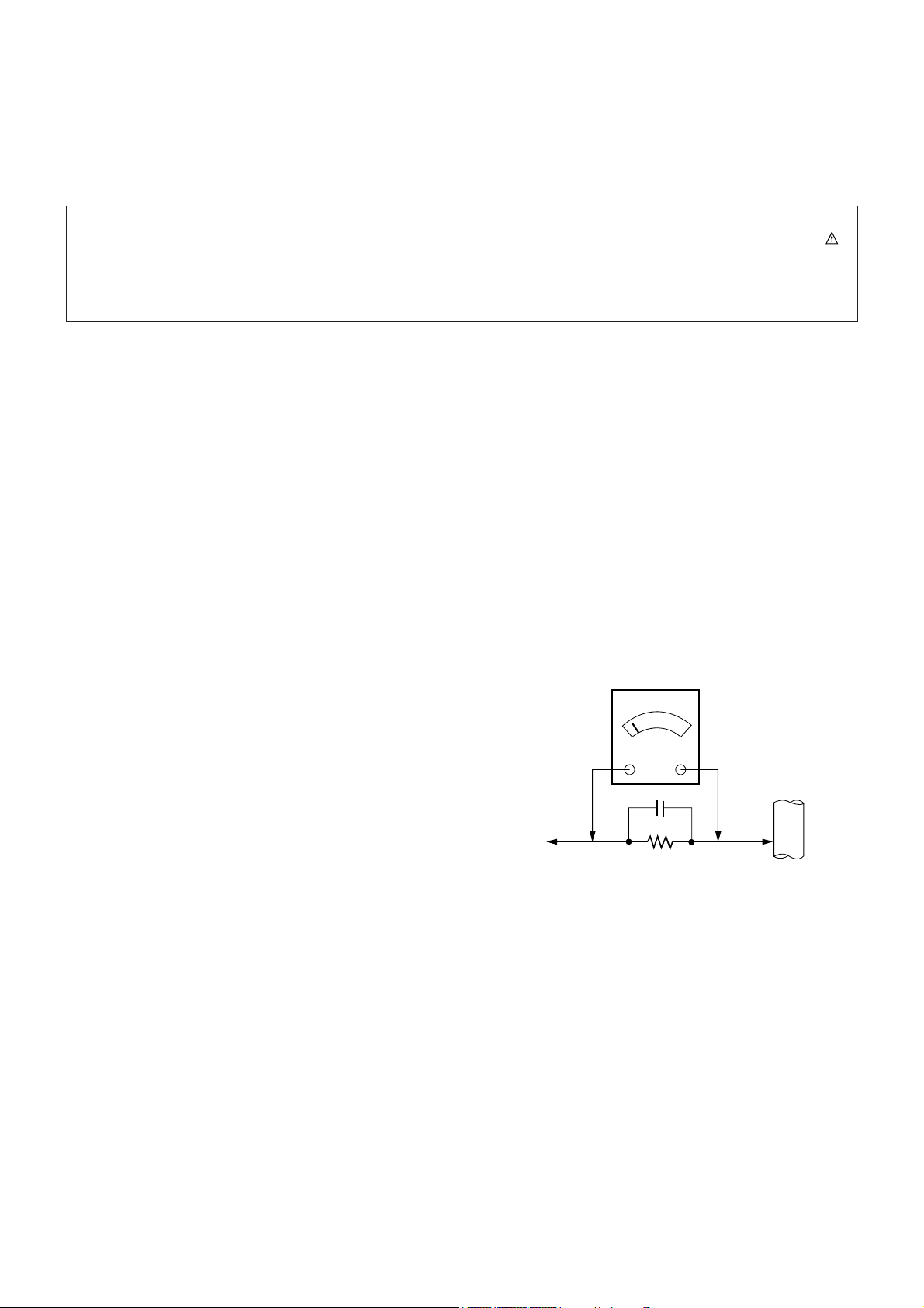
Leakage Current Hot Check (See below Figure)
Plug the AC cord directly into the AC outlet.
Do not use a line Isolation Transformer during this check.
Connect 1.5K/10watt resistor in parallel with a 0.15uF capacitor
between a known good earth ground (Water Pipe, Conduit, etc.)
and the exposed metallic parts.
Measure the AC voltage across the resistor using AC
voltmeter with 1000 ohms/volt or more sensitivity.
Reverse plug the AC cord into the AC outlet and repeat AC
voltage measurements for each exposed metallic part. Any
voltage measured must not exceed 0.75 volt RMS which is
corresponds to 0.5mA.
In case any measurement is out of the limits specified, there is
possibility of shock hazard and the set must be checked and
repaired before it is returned to the customer.
Leakage Current Hot Check circuit
1.5 Kohm/10W
To Instrument's
exposed
METALLIC PARTS
Good Earth Ground
such as WATER PIPE,
CONDUIT etc.
AC Volt-meter
IMPORTANT SAFETY NOTICE
0.15uF
POWERMUTE
TV/AV
MULTIMEDIA
LIST ARC
MENU
PR
PR
VOL
OK
1 2 3
4 5 6
7
PSM
SSM
8 9
0
VOL
SPLIT ZOOM
PIP/DW
SLEEP
REVEAL
TEXT/
PIP PR+
WIN. SIZE
MIX
PIP PR-
POSITION
TIME
SWAP
HOLD
INDEX
PIP INPUT
?
i
I/II
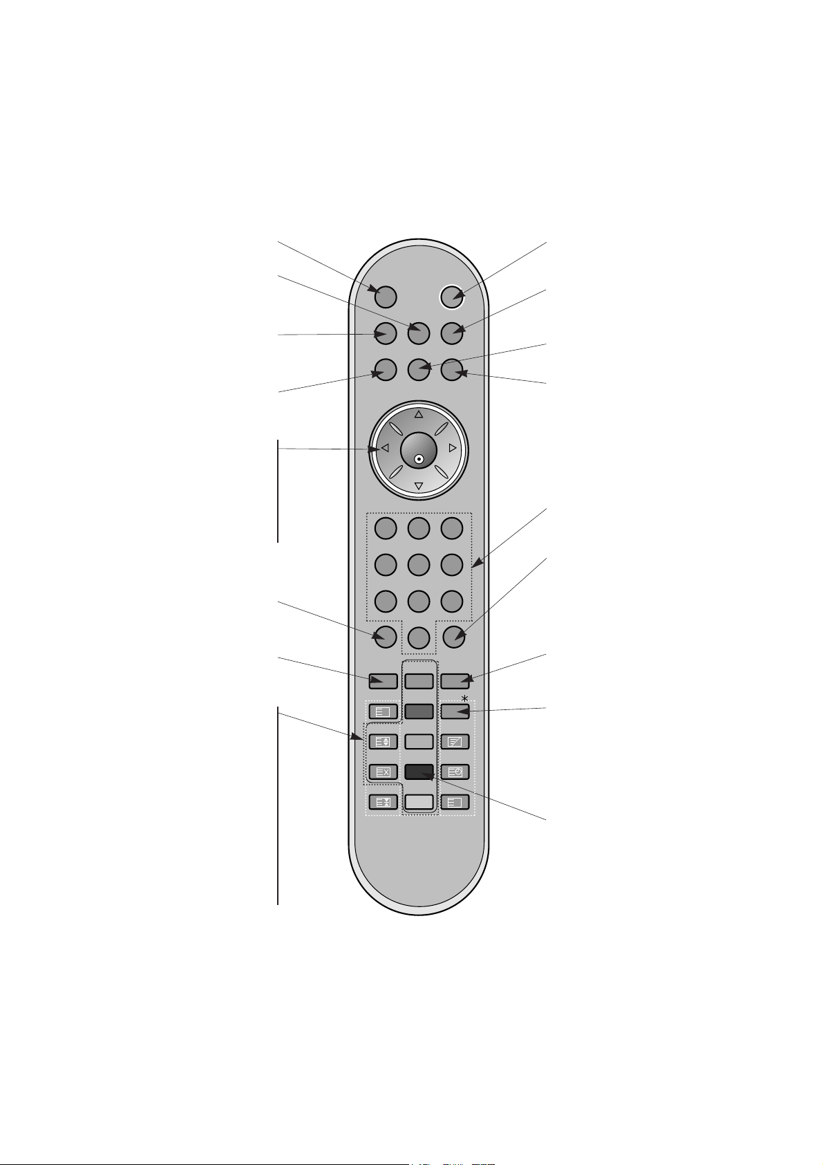
MULTIMEDIA
Selects the Component, RGB or DVI
modes.
switches the set on from standby.
PIP/DW
Switches the sub picture on or off.
Selects PIP or DW modes.
PIP PR + /-
Selects a programme for the sub picture.
SWAP
Alternates between main and sub pic-
ture.
PIP INPUT
Selects the input mode for the sub pic-
ture.
WIN.SIZE
Adjusts the sub picture size.
POSITION
Moves the sub picture to
DD/ EE
or FF / GG
direction.
POWER
switches the set on from standby or
off to standby.
ARC
Changes the picture format.
MENU
Displays on screen menus one by
one.
Exits the current menu.
Memorizes menu changes.
SWAP
Returns to the previously viewed
programme.
Note : This function works only
when Favourite programme is set to
Off. Otherwise each press of this but-
ton will select a stored favorite programme.
SSM
To select the sound appropriate to
your viewing programme character.
NUMBER buttons
SLEEP
Sets the sleep timer.
I/II
Selects the language during dual language broadcast.
Selects the sound output.
TEXT/
*
These buttons are used for teletext.
For further details, see the ÔTeletextÕ
section.
Note : In teletext mode, the PIP PR
+/-, SWAP and PIP INPUT buttons are
used for teletext function.
LIST
Displays the programme table.
TV/AV
Selects the TV, AV, Component, RGB
or DVI modes.
switches the set on from standby.
MUTE
Switches the sound on or off.
DD/ EE
(Programme Up/Down)
selects a programme or a menu item.
switches the set on from standby.
FF/ GG
(Volume Up/Down)
adjusts the volume.
adjusts menu settings.
OK
accepts your selection or displays the
current mode.
PSM
Adjusts the factory preset picture
according to the room.
SPLIT ZOOM
Enlarge the screen with regular
ration.
- 4 -
DESCRIPTION OF CONTROLS
- 5 -
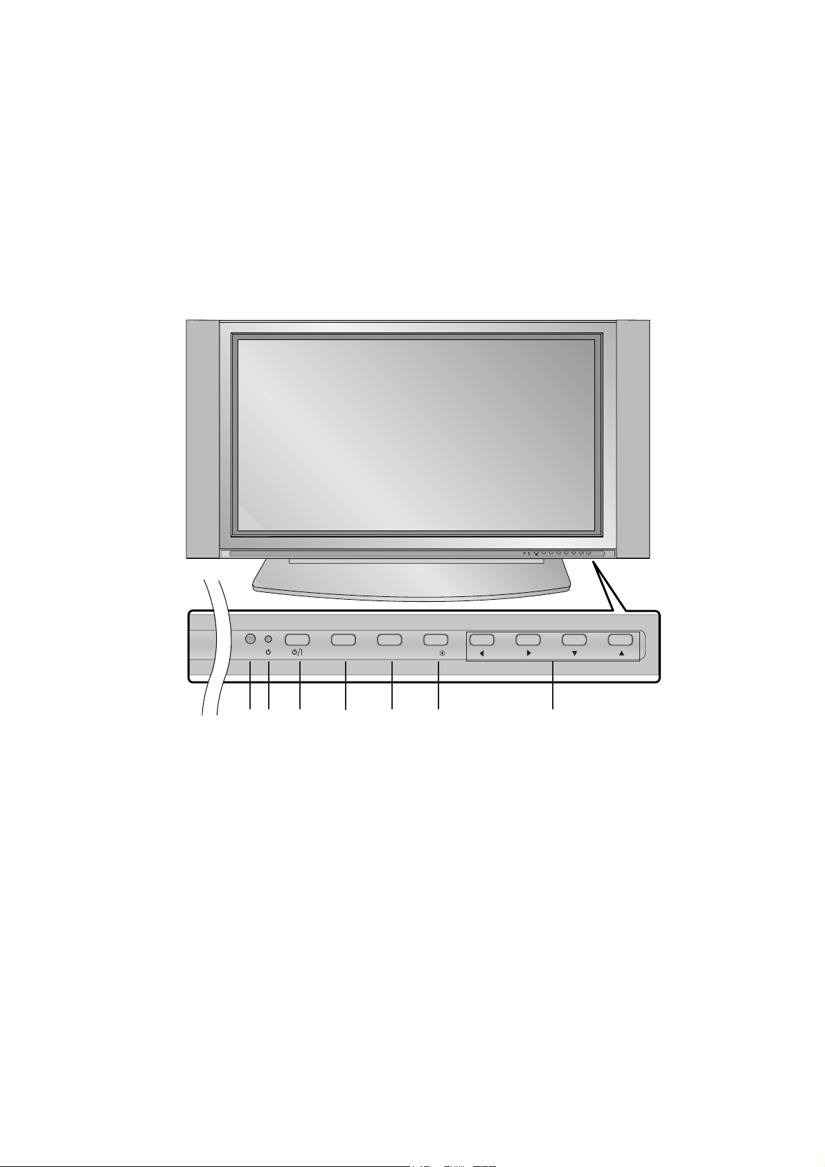
<Front Panel Controls>
PR
VOL
MENUTV/AV OK
PR
VOL
MENUTV/AV OK
1
32
4
5 6 7
1. Remote Control Sensor
2. Power Indicator
Illuminates red in standby mode, Illuminates green when the
set is turned on.
3. Power Button
Switches the set on from standby or off to standby.
4. TV/AV Button
Selects the TV, AV, Component, RGB or HDMI modes.
Switches the set on from standby.
5. MENU
Displays on screen menus one by one.
Exits the current menu.
Memorizes menu changes.
6. OK
Accepts your selection or displays the current mode.
7. DD / EE (Programme Up/Down)
Selects a programme or a menu item.
Switches the set on from standby.
FF / GG (Volume Up/Down)
Adjusts the volume.
Adjusts menu settings.
- 6 -
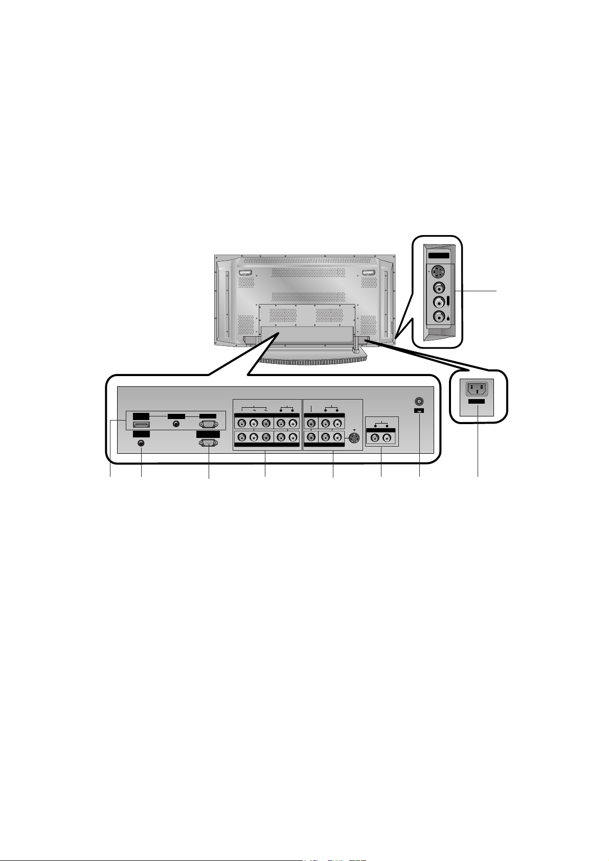
<Back Panel>
S-VIDEO
VIDEOAUDIOR
L/MONO
A/V INPUT2A/V INPUT2
AC INPUT
RS-232C INPUT
(CONTROL/SERVICE)
S-VIDEOS-VIDEO
(MONO)
AUDIO AUDIO
L R
AUDIO AUDIO
L R
AUDIO AUDIO
L R
Antenna
VIDEO VIDEO
REMOTE
CONTROL
HDMI/
DVI(VIDEO)
AUDIO INPUT
RGB INPUT
VIDEOVIDEO
COMPONENTCOMPONENT INPUT INPUT 2 2
COMPONENTCOMPONENT INPUT INPUT 1 1
MONITMONITOR OUTPUTOR OUTPUT
A/V INPUTA/V INPUT 1 1
VVARIABLE ARIABLE AUDIO OUTAUDIO OUT
1. HDMI(DVI VIDEO) / AUDIO INPUT / RGB INPUT
Connect the monitor output socket of the PERSONAL COMPUTER, DVD or STB to this socket.
Note: If you want to use RGB/DVI audio, we strongly
recommend that you use the cable that has a core, or the
EMI Filter core along with separate cable.
2. CONTROL LOCK / REMOTE CONTROL
3. RS-232C INPUT(CONTROL/SERVICE) PORT
Connect to the RS-232C port on a PC.
4. COMPONENT INPUT
Connect DVD video outputs to Y, PB, PR of COMPONENT
INPUT and audio outputs to Audio sockets of AUDIO INPUT.
5. VIDEO/AUDIO IN/OUT SOCKETS (A/V INPUT 1)
Connect the video/audio out sockets of external equipment
to these sockets.
S-VIDEO/AUDIO IN SOCKETS
Connect the S-VIDEO out socket of an VCR to the S-VIDEO
socket.
Connect the audio out sockets of the VCR to the audio sockets as in A/V INPUT 1.
6. VARIABLE AUDIO OUTPUT
7. ANTENNA INPUT
8. POWER CORD SOCKET
This the set operates on an AC power. The voltage is indicated on the Specifications page. Never attempt to operate the
set on DC power.
9. AUDIO/VIDEO INPUT (A/V INPUT 2)
S-VIDEO/AUDIO IN SOCKETS
1
4
2
3 5
7
8
6
9

- 7 -
RGB / HDMI mode
Resolution
640x350
720x400
640x480
848x480
800x600
Horizontal
Frequency(KHz)
Vertical
Frequency(Hz)
852x480
832x624
1024x768
1152x864
1152x870
1280x960
1280x1024
70.09
85.08
70.08
85.03
59.94
66.66
72.80
75.00
85.00
60.00
70.00
75.00
60.00
70.00
75.00
56.25
60.31
72.18
75.00
85.06
74.55
60.00
70.06
75.02
85.00
60.05
70.01
75.00
75.06
60.02
60.02
31.468
37.861
31.469
37.927
31.469
35.000
37.861
37.500
43.269
31.500
37.799
39.375
31.500
37.799
39.375
35.156
37.879
48.077
46.875
53.674
49.725
48.363
56.476
60.023
68.677
54.348
63.995
67.500
68.681
60.023
63.981
- 8 -
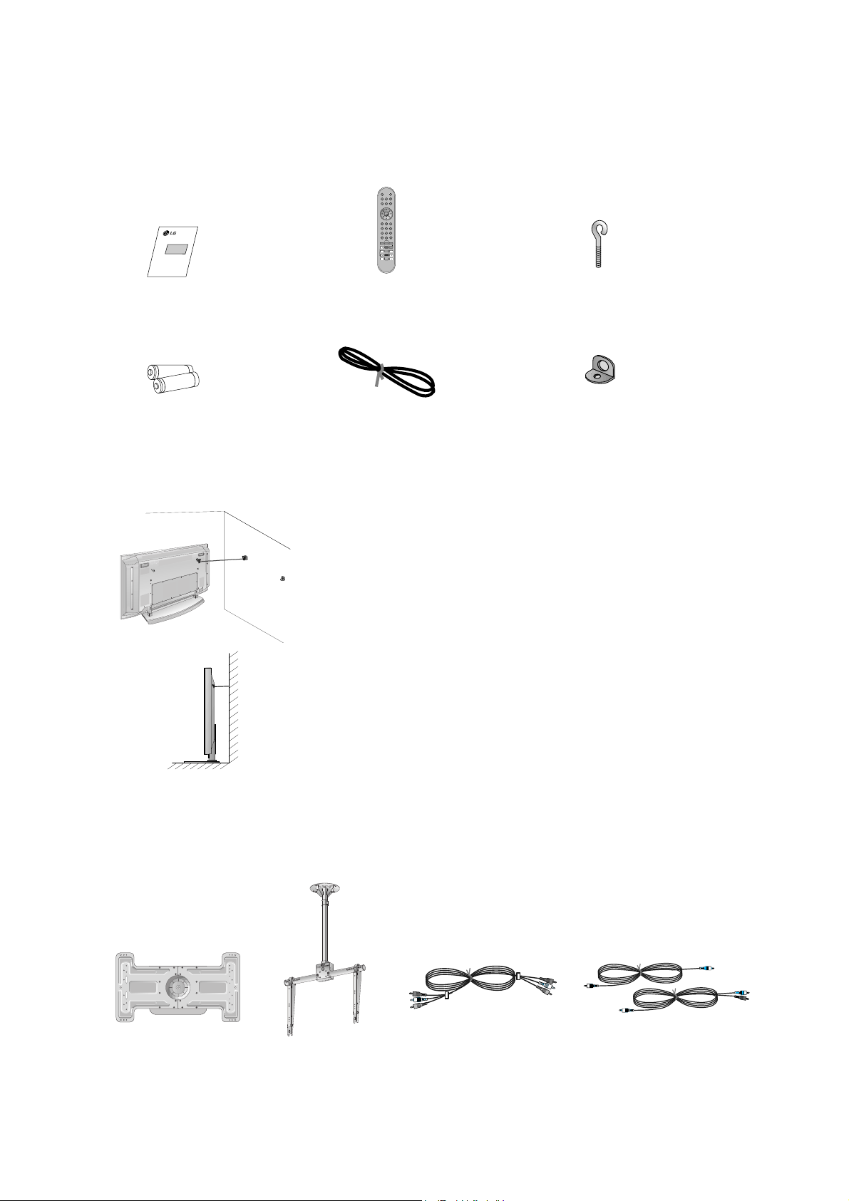
AS mark
LG TV
OwnerÕs Manual
1.5V
1.5V
Alkaline batteries
Power Cord
POWERMUTE
TV/AV
MULTIMEDIA
LIST ARC
MENU
PR
PR
VOL
OK
1 2 3
4 5 6
7
PSM
SSM
8 9
0
VOL
SPLIT ZOOM
PIP/DW
SLEEP
REVEAL
TEXT/
PIP PR+
WIN. SIZE
MIX
PIP PR-
POSITION
TIME
SWAP
HOLD
INDEX
PIP INPUT
?
i
I/II
Remote Control handset
- Optional extras can be changed or modified for quality improvement without any notification new optional extras can be
added.
- Contract your dealer for buying these items.
Optional Extras
Accessories
Accessories
Tilt wall mounting bracket
Video cables Audio cables
Ceiling mounting bracket
40
42
50
42
40
- Secure the TV assembly by joinning it to a wall by using the Eye Bolts/Wall brackets.
Joinning the TV assembly to the wall to protect the set tumbling
¥ After the set must be mounted on a desktop, install the Eye Bolts on the set as
shown.
Insert the 2 Eye Bolts and tighten securely, in the holes on the bracket.
Install the wall brackets on the wall with 2 bolts, (not supplied with the product),
as shown.
Match the height of the Eye Bolts and the wall brackets.
Check to be sure the brackets are tightened securely.
¥ Secure the TV assembly to the wall with strong strings or wound wire cables,
(not supplied with the product), as shown.
2-Wall brackets
2-Eye Bolts
SPECIFICATIONS
NOTE : Specifications and others are subject to change without notice for improvement
.
- 9 -
V Application Range
This spec is applied to the 42ÓPDP TV used MF-056A Chassis.
V Specification
Each part is tested as below without special appointment.
1) Temperature : 25±5¡C (77±9¡F), CST : 40±5
2) Relative Humidity: 65
±10%
3) Power Voltage: Standard Input voltage (100-240V~, 50/60Hz)
* Standard Voltage of each product is marked by models.
4) Specification and performance of each parts are followed each drawing and specification by part number in accordance with BOM.
5)
The receiver must be operated for about 20 minutes prior to the adjustment
.
V Test Method
1) Performance : LGE TV test method followed.
2) Demanded other specification
Safety: CE, IEC specification
EMC : CE, IEC
V General Specification
1. Module Specification
Remark
Safety : IEC/EN60065, EMI : EN55013, EMS : EN55020
Model Name
42PX3RV-ZA
Market
EU
Remark
PDP
LGE SPEC
Maker : SONY/ Sanken
Specification
42 inch wide Color Display Module
16:9
PDP42V7xxxx
RGB Closed Type, Film Filter
1) Temp : 0~40 deg
2) Humidity : 0~85%
1) Temp : -20~60 deg
2) Humidity : 0~85%
100-240V~, 50/60Hz
No
1
2
3
4
5
6
Item
Display Screen Device
Aspect Ratio
PDP Module
Operating Environment
Storage Environment
Input Voltage
2. Model Specification (42PX3RV-ZA)
- 10 -
Item
Market
Broadcasting system
Available Channel
Receiving system
SCART Jack(3EA)
Video Input (2EA)
S-Video Input(3EA)
Component Input(1EA)
RGB Input(1EA)
HDMI Input(1EA)
Audio Input(4EA)
Wired Control
Audio variable out
No
1
2
3
4
5
6
7
8
9
10
11
12
13
Specification
EU
PAL B/G/I/D/K, NTSC
BAND PAL NTSC
VHF/UHF C1~C69 2~83
CATV S1~S47 1~71
Upper Heterodyne
PAL, SECAM, NTSC
PAL, SECAM, NTSC
PAL, SECAM, NTSC
Y/Cb/Cr, Y/Pb/Pr
RGB-PC
RGB-DTV
HDMI-PC
HDMI-DTV
PC Audio, Component(1EA), AV(2EA)
Remark
4 System :
PAL, SECAM, NTSC,PAL60
4 System :
PAL, SECAM, NTSC,PAL60
4 System :
PAL, SECAM, NTSC,PAL60
L/R Input
- 11 -
ADJUSTMENT INSTRUCTIONS
1. Application Object
These instructions apply to the MF-056A Chassis.
2. Specification
(1) Because this is not a hot chassis, it is not necessary to use
an isolation transformer. However, the use of isolation
transformer will help protect test instrument.
(2) Adjustment must be done in the correct order.
(3) The adjustment must be performed in the circumstance of
25±5¡C of temperature and 65±10% of relative humidity if
there is no specific designation.
(4) The input voltage of the receiver must keep 100-220V,
50/60Hz.
(5) The receiver must be operated for about 15 minutes prior
to the adjustment.
O After RGB Full white HEAT-RUN Mode, the receiver must
be operated prior to adjustment.
O Enter into HEAT-RUN MODE
1) Press the POWER ON KEY on R/C for adjustment.
2) OSD display and screen display 100% full WHITE
PATTERN.
[ Set is activated HEAT-RUN without signal generator in
this mode.
[ Single color pattern(RED/BLUE/GREEN) of HEAT-RUN
mode uses to check PANEL.
Caution) If you turn on a still screen more than 20 minutes
(Especially digital pattern, cross hatch pattern), after
image may be occur in the black level part of the
screen.
3. Channel memory
3-1. Setting up the LGIDS
1) Install the LGIDS. (idsinst.exe)
2) After installation, restart your PC.
3) Extract [files.zip] to folder [c:\LGIDS\files].
4) Start LGIDS.
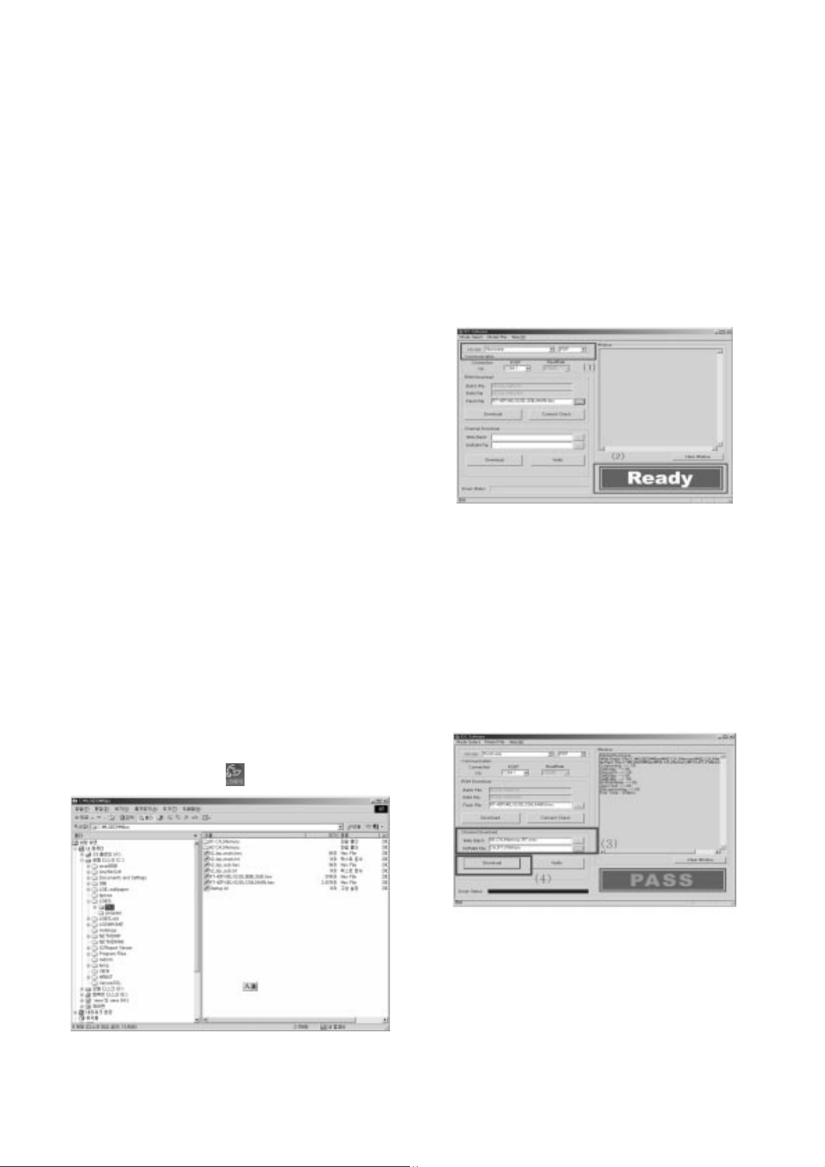
3-2. Channel memory Method
1) Select ÒPDPÓ and ÒHurricaneÓ on Model dialog. And check
your connection in Communication dialog. (If your
connection is ÔNGÕ, then set your PORT(COM1,2,3,...)
correctly.)
2) Connect RS-232C cable and turn on the power.
(If your connection has completed, you can see ÒReadyÓ.)
[ If your set is not an end products but only a board, you
have to make your board to Stand-by state (LED_R). And
you have to Download in Stand_by power state.
3) Select proper CH_memory file(*.nvm) for each model at
[NVRAM Download]
$ [Write Batch]
Next, select proper binary file(*.bin) including the CH
information for each model at [NVRAM File].
4) Click the [Download] button.
It means the completion of the CH memory download if all
items show ÔOKÕ and Status is changed by ÔPASSÕ at the
lower right corner of the window.
5) If you want to check whether the CH information is
memorized correctly or not, click the [Verify] button.
And then compare NVRAM File(*.bin) with the CH
information downloaded.
3-3 Sub program download
1) Select ÒPDPÓ and ÒHurricaneÓ on Model dialog. And check
your connection in Communication dialog. (If your
connection is ÔNGÕ, then set your PORT(COM1,2,3,...)
correctly.)
(Fig. 1)
(Fig. 3)
(Fig. 3-1)
- 12 -
2) Connect RS-232C cable and turn on the power. (Use the
special Cable For Sub-program) (If your connection has
completed, you can see ÒReadyÓ)
4. POWER PCB Assy Voltage
Adjustments
(Va, Vs Voltage Adjustments)
4-1. Test Equipment : D.M.M. 1EA
4-2. Adjustment Method
[P/No 3501V00220A(Sanken PSU) B/D]
(1) Va Adjustment
1) After receiving 100% Full White Pattern, HEAT RUN.
2) Connect + terminal of D.M.M to Va pin of P807, connect
- terminal to GND pin of P807.
3) After turning RV501, voltage of D.M.M adjustment as
same as Va voltage which on label of panel right/top.
(Deviation; ±0.5V)
(2) Vs Adjustment
1) Connect + terminal of D.M.M to Vs pin of P807, connect
Ð terminal to GND pin of P805.
2) After turning RV401, voltage of D.M.M adjustment as
same as Va voltage which on label of panel right/top.
(Deviation; ±0.5V)
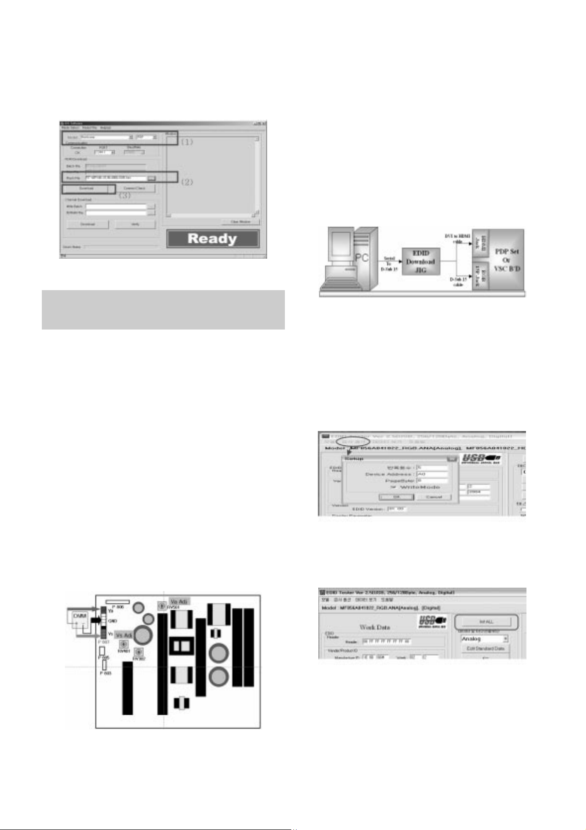
5. EDID (The Extended Display
Identification Data)/ DDC (Display
Data Channel) download
5-1. Required Test Equipment
1) Adjusting PC with S/W for writing EDID Data.(S/W : EDID
TESTER Ver.2.5)
2) A Jig for EDID Download
3) Cable : Serial(9Pin or USB) to D-sub 15Pin cable, D-sub
15Pin cable, DVI to HDMI cable
5-2. Setting of device
5.3. Preparation for Adjustment
1) As above Fig. 5, Connect the Set, EDID Download Jig, PC
& Cable.
2) Turn on the PC & EDID Download Jig. And Execute the
S/W : EDID TESTER Ver,2.5
3) Set up S/W option
Repeat Number : 5
Device Address : A0
PageByte : 8
4) Power on the Set
5.4. Sequence of Adjustment
(1) DDC data of Analog-RGB
1) Init the data
2) Load the EDID data.(Open File)
[Analog-RGB : MF056A_RGB.ANA]
[digital(HDMI) : MF056A_DMI.DVI]
3) Set the S/W as below.
4) Push the ÒWrite Data & VerifyÓbutton. And confirm ÒYesÓ.
5) If the writing is finished, you will see the ÒOKÓ message.
Each PCB assembly must be checked by check JIG set.
(Because power PCB Assembly damages to PDP Module,
especially be careful)
(Fig. 4) Connection diagram of power adjustment for measuring
(Fig. 5) Connection Diagram of DDC download
 Loading...