

LG 42PX3DLV Service Manual

PLASMA TV
SERVICE MANUAL
CAUTION
BEFORE SERVICING THE CHASSIS,
READ THE SAFETY PRECAUTIONS IN THIS MANUAL.
CHASSIS : AF-044C
MODEL : 42PX3DBV 42PX3DBV-UC
MODEL : 42PX3DLV 42PX3DLV-UC
CANADA : http//biz.lgservice.com
USA : http//www.lgservice.com
: http//lgservice.com/techsup.html
PR
VOL
MENUTV/AV OK
- 2 -
SAFETY PRECAUTIONS
Many electrical and mechanical parts in this chassis have special safety-related characteristics. These parts are identified by in
the Schematic Diagram and Replacement Parts List.
It is essential that these special safety parts should be replaced with the same components as recommended in this manual to
prevent X-RADIATION, Shock, Fire, or other Hazards.
Do not modify the original design without permission of manufacturer.
General Guidance
An lsolation Transformer should always be used during
the servicing of a receiver whose chassis is not isolated from
the AC power line. Use a transformer of adequate power rating
as this protects the technician from accidents resulting in
personal injury from electrical shocks.
It will also protect the receiver and it's components from being
damaged by accidental shorts of the circuitary that may be
inadvertently introduced during the service operation.
If any fuse (or Fusible Resistor) in this monitor is blown, replace
it with the same specified type.
When replacing a high wattage resistor (Oxide Metal Film
Resistor, over 1W), keep the resistor 10mm away from PCB.
Keep wires away from high voltage or high temperature parts.
Leakage Current Cold Check(Antenna Cold Check)
With the instrument AC plug removed from AC source,
connect an electrical jumper across the two AC plug prongs.
Place the AC switch in the on positioin, connect one lead of
ohm-meter to the AC plug prongs tied together and touch other
ohm-meter lead in turn to each exposed metallic parts such as
antenna terminals, phone jacks, etc.
If the exposed metallic part has a return path to the chassis, the
measured resistance should be between 1MΩ and 5.2MΩ.
When the exposed metal has no return path to the chassis the
reading must be infinite.
An-other abnormality exists that must be corrected before the
receiver is returned to the customer.
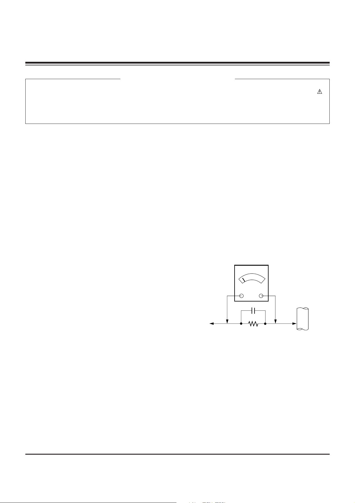
Leakage Current Hot Check (See below Figure)
Plug the AC cord directly into the AC outlet.
Do not use a line Isolation Transformer during this check.
Connect 1.5K/10watt resistor in parallel with a 0.15uF capacitor
between a known good earth ground (Water Pipe, Conduit, etc.)
and the exposed metallic parts.
Measure the AC voltage across the resistor using AC
voltmeter with 1000 ohms/volt or more sensitivity.
Reverse plug the AC cord into the AC outlet and repeat AC
voltage measurements for each esposed metallic part. Any
voltage measured must not exceed 0.75 volt RMS which is
corresponds to 0.5mA.
In case any measurement is out of the limits sepcified, there is
possibility of shock hazard and the set must be checked and
repaired before it is returned to the customer.
Leakage Current Hot Check circuit
CANADA: LG Electronics Canada, Inc. 550 Matheson
Boulevard East Mississauga, Ontario L4Z 4G3
USA : LG Customer Interactive Center
P.O.Box 240007, 201 James Record Road Huntsville,
AL 35824
Digital TV Hotline 1-800-243-0000
1.5 Kohm/10W
To Instrument's
exposed
METALLIC PARTS
Good Earth Ground
such as WATER PIPE,
CONDUIT etc.
AC Volt-meter
IMPORTANT SAFETY NOTICE
0.15uF

- 3 -
DESCRIPTION OF CONTROLS...........................................4
SPECIFICATIONS.................................................................8
ADJUSTMENT INSTRUCTIONS ..........................................9
BLOCK DIAGRAM...............................................................14
EXPLODED VIEW...............................................................16
EXPLODED VIEW PARTS LIST.........................................17
REPLACEMENT PARTS LIST............................................18
SCHEMATIC DIAGRAM..........................................................
PRINTED CIRCUIT BOARDS.................................................
TABLE OF CONTENTS
- 4 -
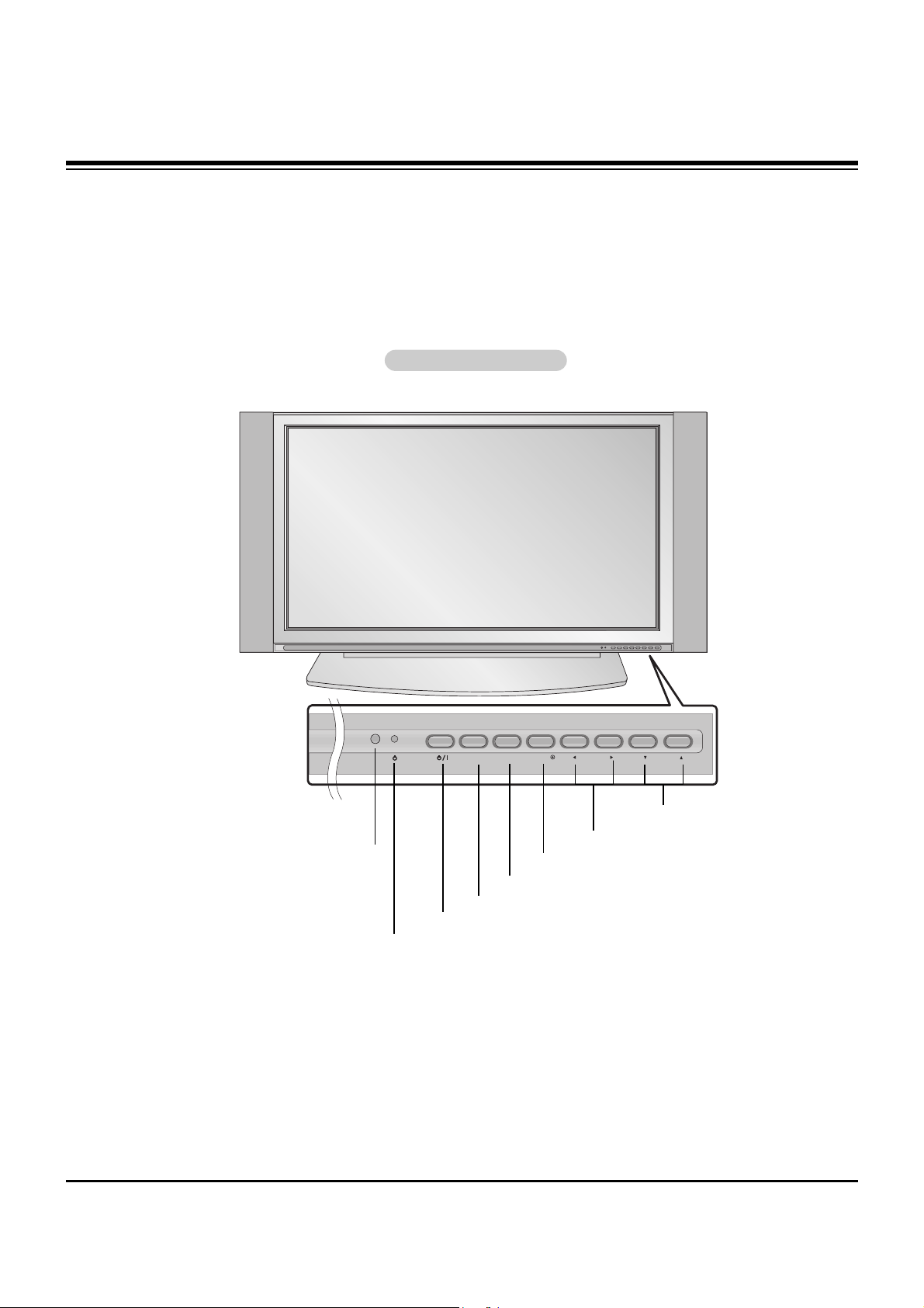
Controls
Controls
- This is a simplified representation of front panel.
Image shown may be somewhat different from your TV.
Front Panel Controls
Front Panel Controls
MENU
VOL
CH
TV/VIDEO
ENTER
POWER Button
Remote Control Sensor
VOLUME (
FF , GG
) Buttons
Power Standby Indicator
Illuminates red in standby mode, Illuminates
green when the TV is turned on.
CHANNEL (EE, DD) Buttons
MENU Button
TV/VIDEO Button
ENTER Button
DESCRIPTION OF CONTROLS
- 5 -
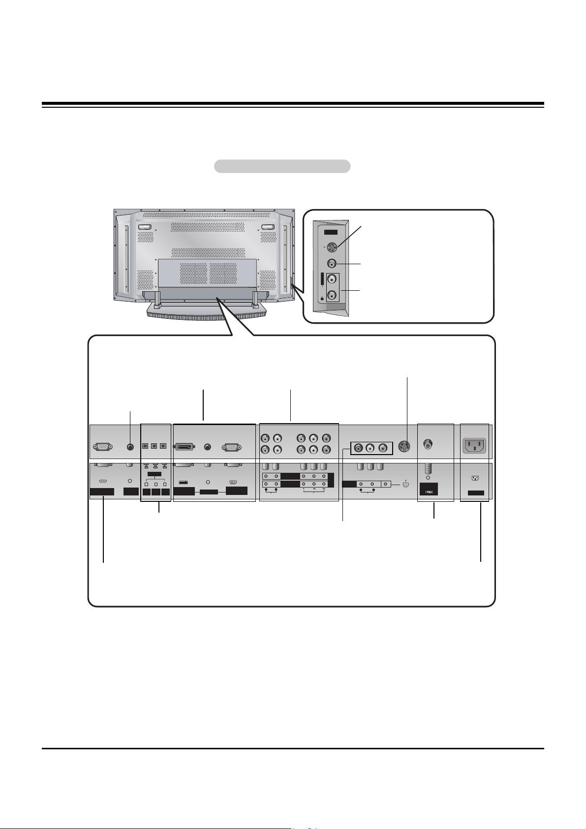
Connection Options
Connection Options
Back Connection Panel
Back Connection Panel
Antenna Inputs
Connect cable or antenna signals to the
TV, either directly or through your cable
box.
DVI Input/Audio Input/RGB
Input
Connect the monitor output connector from a PC to the appropriate input port.
Digital Audio (DVI: Digital Visual
Interface/Component1) Input/
Digital Audio Output
Connect digital audio from various types
of equipment. Note: In standby mode,
these ports will not work.
Audio/Video Input 1
Connect audio/video out-
put from an external
device to these jacks.
DVD/DTV Input (Component
1-2)
Connect a component
video/audio device to these
jacks.
Remote Control
Port
Connect your wired
remote control here.
S-Video Input
Connect S-Video out from an
S-VIDEO device to the SVIDEO input.
Power Cord Socket
This TV operates on an AC power. The voltage is indi-
cated on the Specifications page. Never attempt to oper-
ate the TV on DC power.
S-VIDEO Input
A connection available to provide better
picture quality than the video input.
VIDEO Input
Connects the video signal from a video
device.
AUDIO Input
Use to connect to hear stereo sound
from an external device.
RS-232C INPUT
(CONTROL/SERVICE) PORT
Connect to the RS-232C port
on a PC.
DESCRIPTION OF CONTROLS
A/V 2
S-VIDEO VIDEO
L / MONO
AUDIO
R
RS-232C INPUT
(CONTROL/SERVICE)
REMOTE
CONTROL
DIGITAL AUDIO
(OPTICAL)
COMPONENT1
INPUT
OUTPUT
DVI INPUT
(PC/DTV INPUT)
AUDIO INPUT
DVI
INPUT
COMPONENT 2
RGB INPUT
(PC/DTV INPUT)
R L
AUDIO INPUT
COMPONENT 1
VIDEO INPUT
DVD
/DTV
INPUT
A/V
R L
AUDIO
(MONO)
VIDEO
INPUT 1
S-VIDEO
Antenna
Analog/DTV
AC INPUT
- 6 -
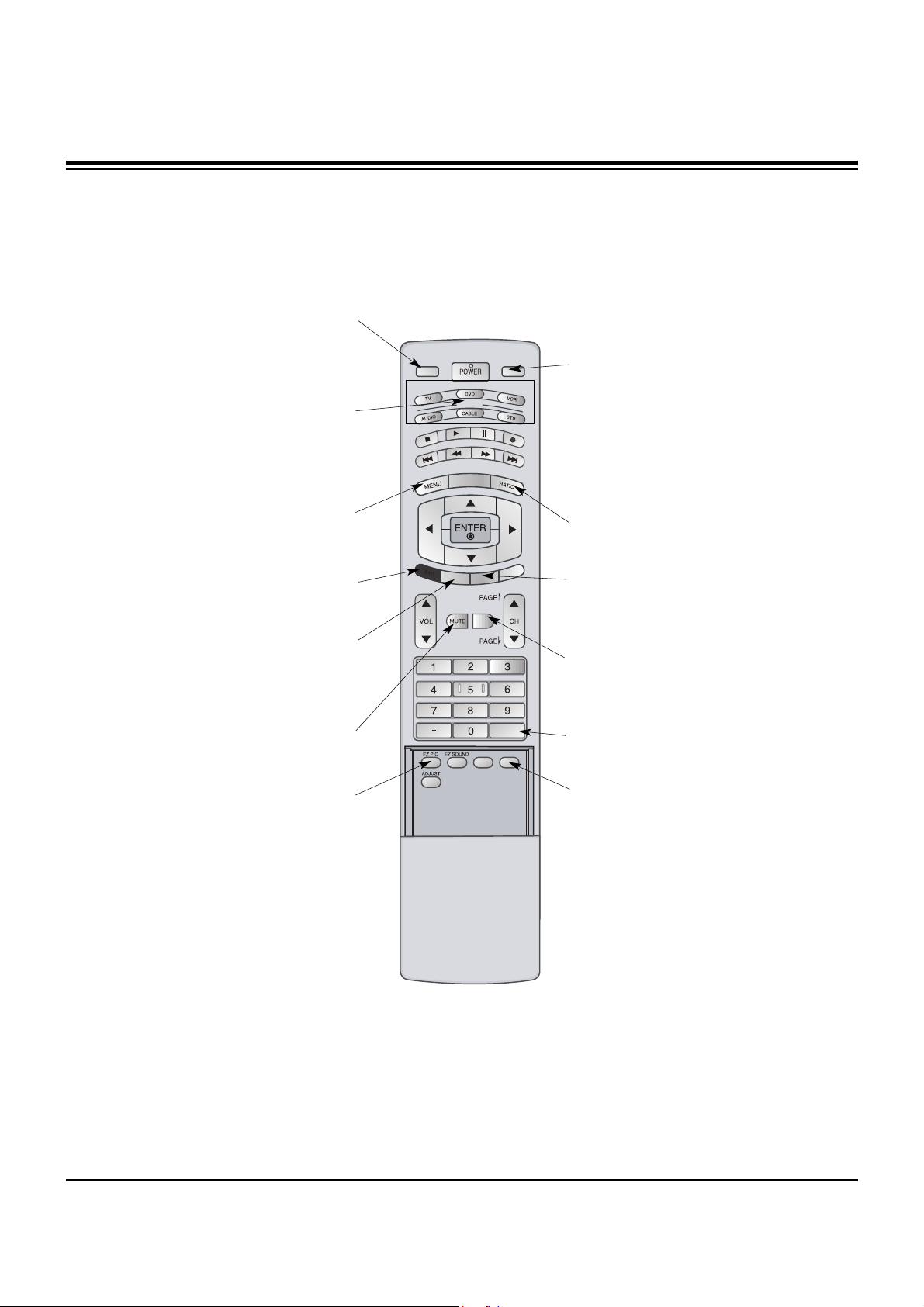
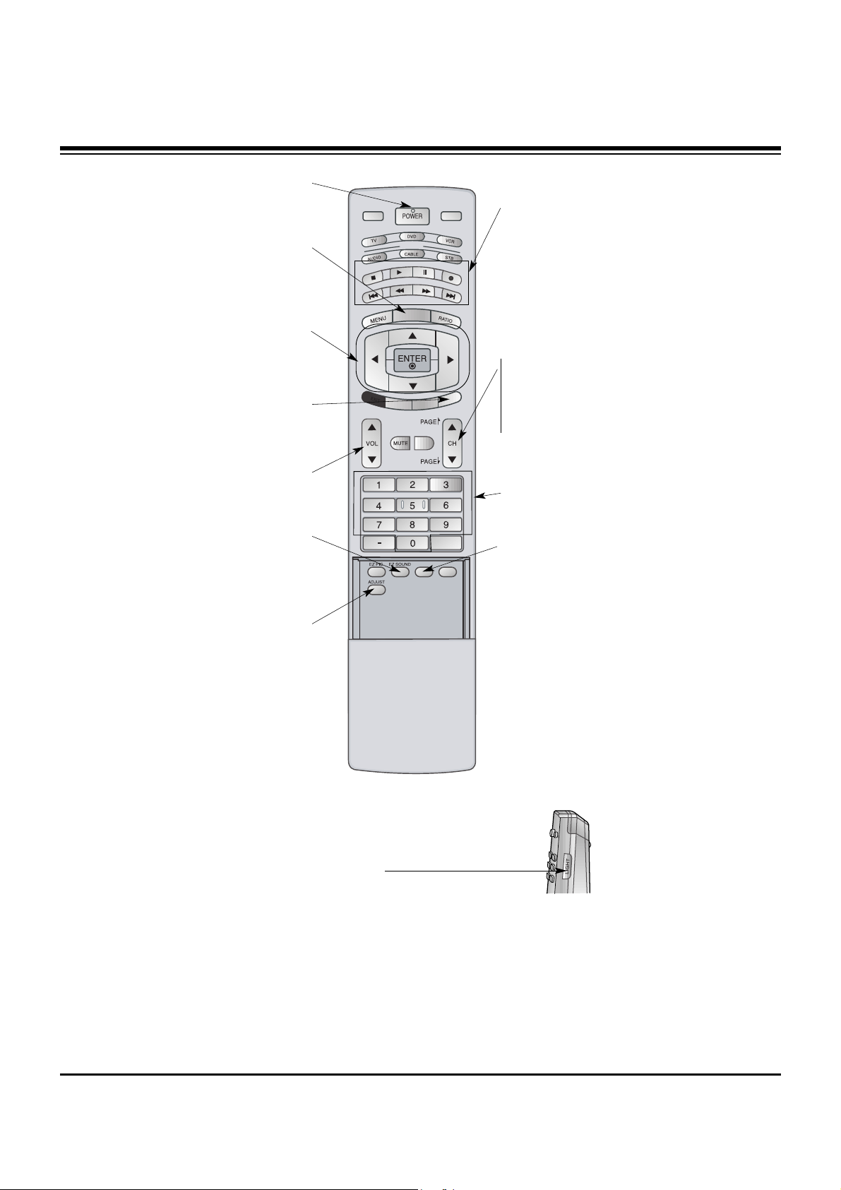
Remote Control Key Functions
Remote Control Key Functions
MODE
FLASHBK
FREEZE
TV/VIDEO
SAP
EXIT
TIMER
CC
XD
COMP/RGB/DVI
INFO
SURF
COMP/RGB/DVI
Selects: Component 1-2, RGB-DTV (or
RGB-PC), DVI-DTV (or DVI-PC) input
sources.
MUTE
Switches the sound on or off.
MODE
Selects the remote operating mode: TV,
DVD, VCR, AUDIO, CABLE or STB. Select
a mode other than TV, for the remote to
operate an external device.
FLASHBK
Tunes to the recent channels.
EXIT
Clears all on-screen displays and returns to
TV viewing from any menu.
TIMER
Lets you select the amount of time before
your TV turns itself off automatically.
MENU
Brings up the main menu to the screen.
EZ PIC
Selects a factory preset picture mode
depending on the viewing environment.
FREEZE
Freezes the currently-viewed picture.
Main picture is frozen.
TV/VIDEO
External input modes rotate in regular
sequence: Antenna, Cable, Video, Front
Video, Component 1-2 and RGB-DTV (or
RGB-PC) input sources.
(Video, Front Video, Component 1-2 input
sources are linked automatically, only if
these are connected )
RATIO
Changes the aspect ratio.
SURF
Scrolls the Favorite channels.
SAP
Selects MTS sound: Mono, Stereo, and
SAP in Analog mode. Change the audio
language in DTV mode.
- When using the remote control, aim it at the remote control sensor on the TV.
DESCRIPTION OF CONTROLS
- 7 -
MODE
FLASHBK
FREEZE
TV/VIDEO
SAP
EXIT
TIMER
CC
XD
COMP/RGB/DVI
INFO
SURF
LIGHT
Illuminates the remote control
buttons of selected mode.
NUMBER buttons
VCR/DVD BUTTONS
• Control some video cassette recorders
or DVD players. ("RECORD" button is not
available for DVD players.)
POWER
Turns your TV or any other programmed
equipment on or off, depending on mode.
CC
Select a closed caption:
Off, CC1~4, Text1~4.
THUMBSTICK (Up/Down/Left/Right/ENTER)
Allows you to navigate the on-screen menus
and adjust the system settings to your pref-
erence.
CHANNEL UP/DOWN
Selects available channels found with EZ
scan.
PAGE UP/PAGE DOWN
Moves from one full set of screen information to the next one.
EZ SOUND
Selects the sound appropriate for the pro-
gram's character.
XD
Switches the XD function on or off.
VOLUME UP/DOWN
Increases/decreases the sound level.
INFO
When you watch the TV, information dis-
plays on top of the screen. Not available in
Component 1-2 and RGB mode.
ADJUST
Adjusts screen position, size, and phase in
PC mode.
DESCRIPTION OF CONTROLS

- 8 -
• The specifications shown above may be changed without prior notice for quality improvement.
MODEL
AC100-240V ~ 50/60Hz
NTSC-M, ATSC, 64 & 256 QAM
VHF 2 ~ 13, UHF 14 ~ 69, CATV 1 ~ 125, CADTV 1 ~ 135. DTV 2 ~ 69
75 Ω
32 ~ 104°F (0 ~ 40°C)
Less than 80%
47.6 / 1210
27.6 / 701
11.6 / 295
66.1 / 30
852 x 480 (Dot)
Width (inches / mm)
Height (inches / mm)
Depth (inches / mm)
Weight (pounds / kg)
Resolution
Power requirement
Television System
Program Coverage
External Antenna Impedance
Operating Temperature Range
Operating Humidity Range
42PX3DBV-UC/42PX3DLV-UC
SPECIFICATIONS
1. Application Object
These instructions are applied to all of the PDP TV, AF-044C.
2. Notes
(1) Because this is not a hot chassis, it is not necessary to use
an isolation transformer. However, the use of isolation
transformer will help protect test instrument.
(2) Adjustments must be done in the correct order.
(3) The adjustments must be performed in the circumstance of
25±5°C of temperature and 65±10% of relative humidity if
there is no specific designation.
(4) The input voltage of the receiver be must kept 110V, 60Hz
when adjusting.
(5) The receiver must be operational for about 15 minutes
prior to the adjustments.
1) After receiving 100% white pattern, the receiver must be
operated prior to adjustment. (Or 5. White Pattern
condition in EZ - Adjust)
2) Enter into White Pattern
- Enter the Ez - Adjust by pressing ADJ Key on Service
Remote Control (S R/C).
- Select the 5. White Pattern using CH +/- Key and
press the Enter(
Y) Key.
Display the 100% Full White Pattern.
[ Set is activated HEAT-RUN without signal generator in
this mode.
3. EPLD Download
(1) Test Equipment: PC, Jig for download
(2) Connect the power of VSC B/D.
(3) Execute download program( ) of PC.
(4) After executing execution hot key (Programmer), icon click
(5) End after confirming
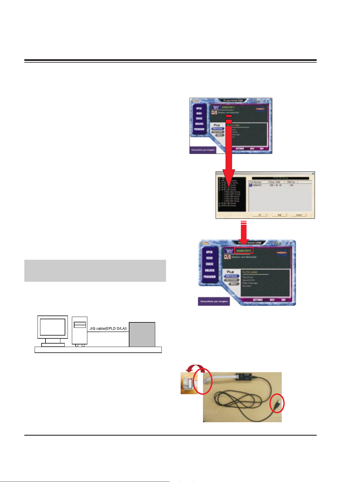
4. SUB MICOM Download
4-1. Select the MICOM Model
Select the MICOM Model.(M16C/6H Group --> M306H3FC)
[ After setting, you need not set, again.
4-2. JIG Connection
Connection to the Micom Port on the TV Board.
(Spot of the red line(an arrow)is connected to the port 1.)
- 9 -
ADJUSTMENT INSTRUCTIONS
If you turn on a still screen more than 20 minutes (Especially
Digital pattern(13 CH), Cross Hatch Pattern), an afterimage
may occur in the black level part of the screen.
PC
VSC
B/D
<Fig 1> Connection Diagram of EPLD Download
<MICOM JIG>
Connection
the Computer
 Loading...