

LG 42PW340, 42PW340-UB, 42PW350, 42PW350-UA, 42PW350U Service Manual
...
PLASMA TV
SERVICE MANUAL
CAUTION
BEFORE SERVICING THE CHASSIS,
READ THE SAFETY PRECAUTIONS IN THIS MANUAL.
CHASSIS : PU11A
MODEL : 42PW340 42PW340-UB
42PW350 42PW350-UA/UE
42PW350U 42PW350U-UC
North/Latin America http://aic.lgservice.com
Europe/Africa http://eic.lgservice.com
Asia/Oceania http://biz.lgservice.com
Internal Use Only
Printed in Korea
P/NO : MFL66306601(1106-REV01)

- 2 -
LGE Internal Use OnlyCopyright ©2011 LG Electronics Inc. All rights reserved.
Only for training and service purposes
CONTENTS
CONTENTS ............................................................................................................................... 2
SAFETY PRECAUTIONS ...........................................................................................................3
SPECIFICATION.........................................................................................................................4
ADJUSTMENT INSTRUCTION ..................................................................................................6
BLOCK DIAGRAM ...................................................................................................................13
EXPLODED VIEW ...................................................................................................................14
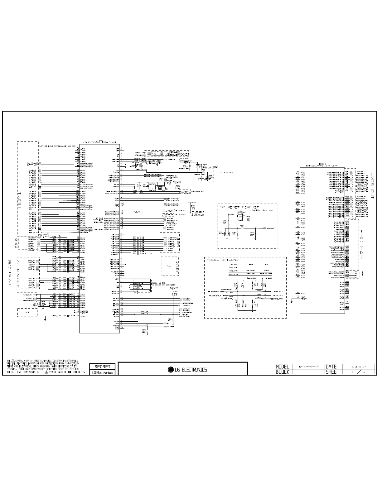
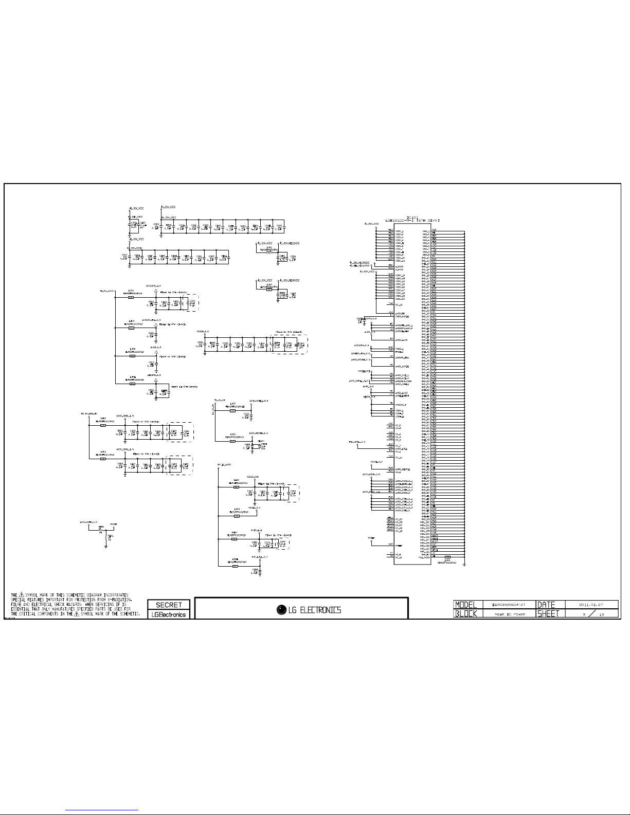
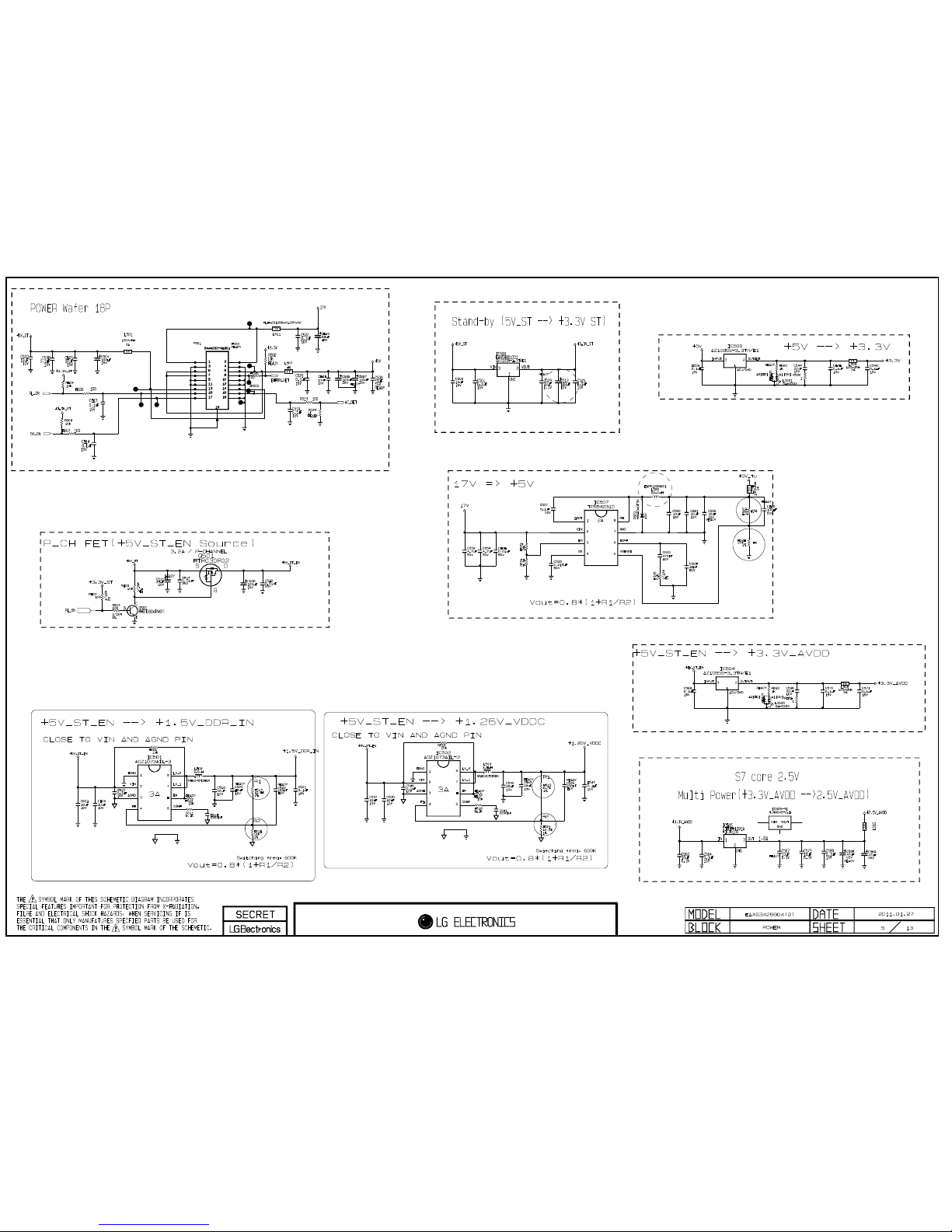
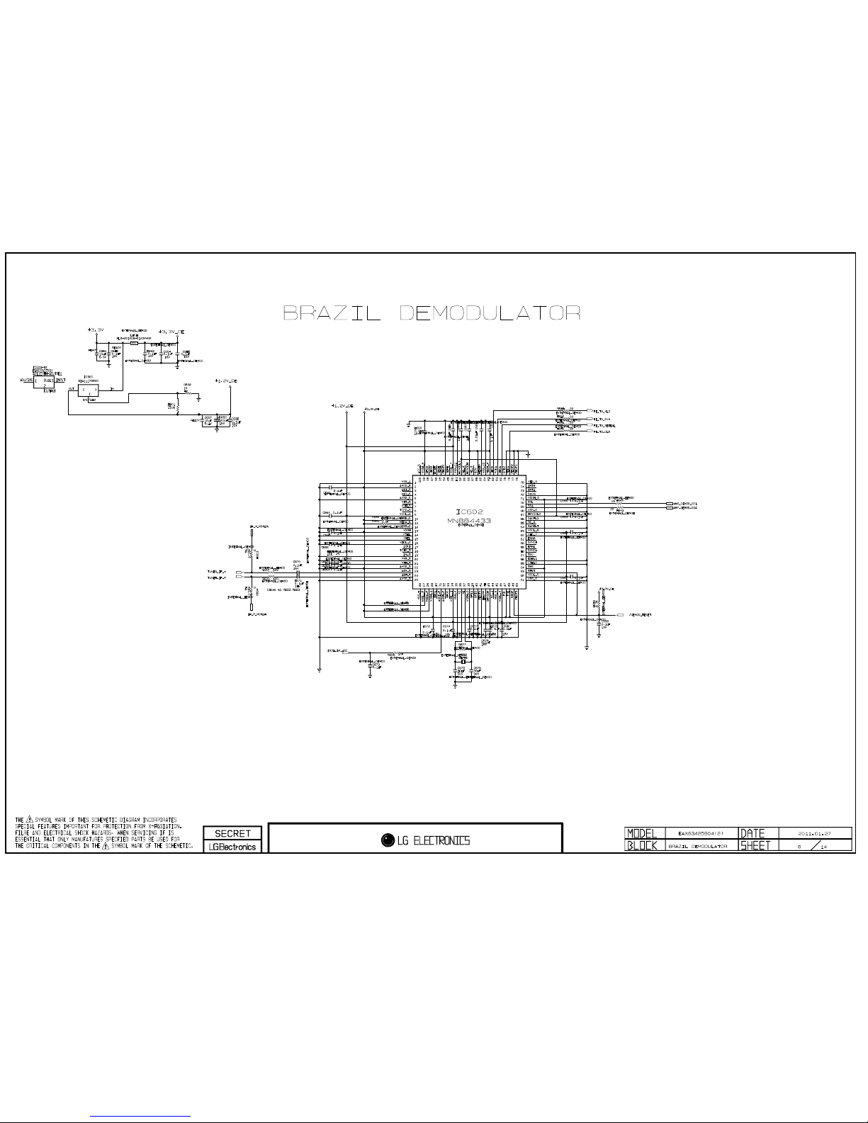
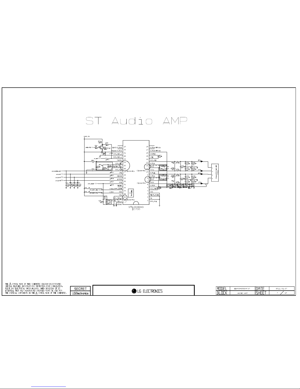
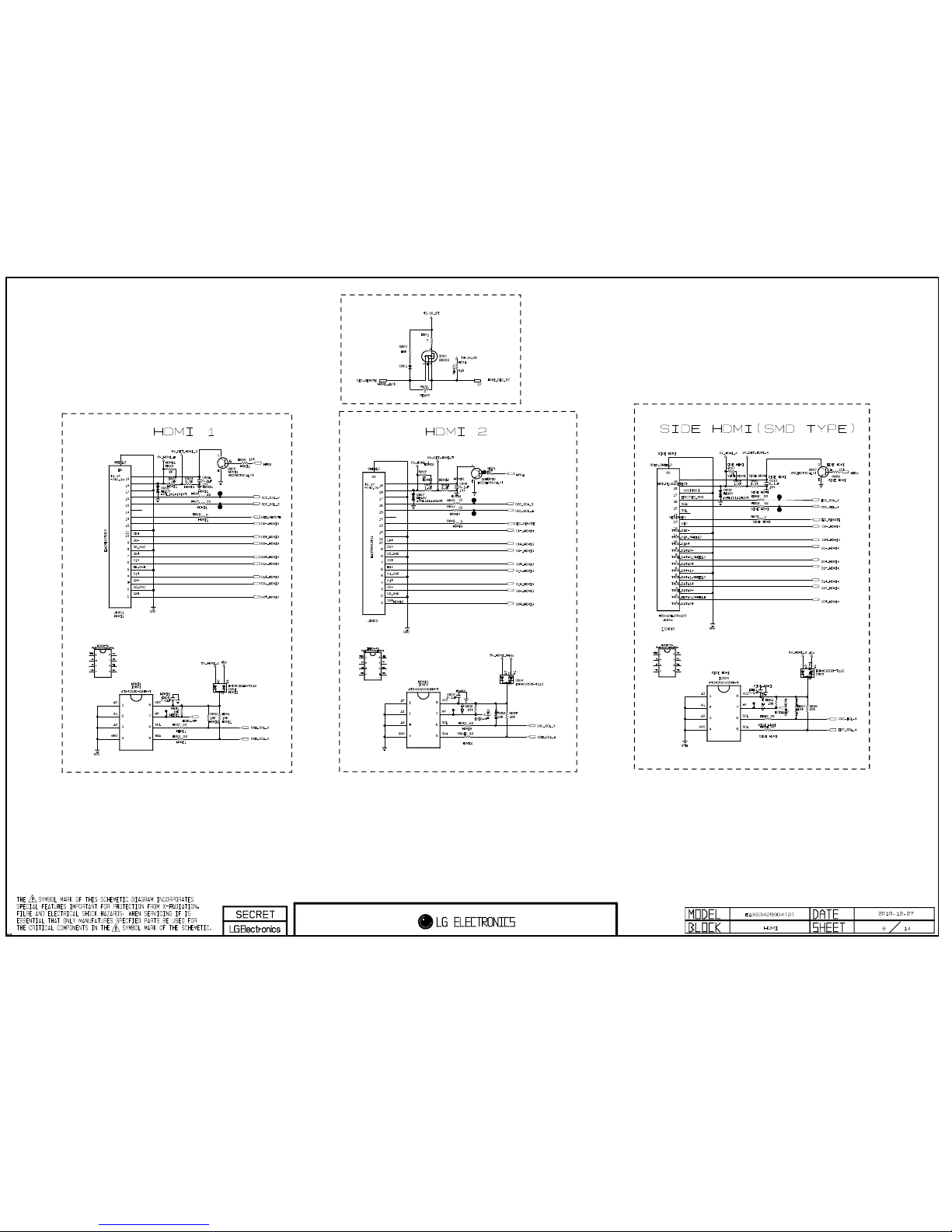
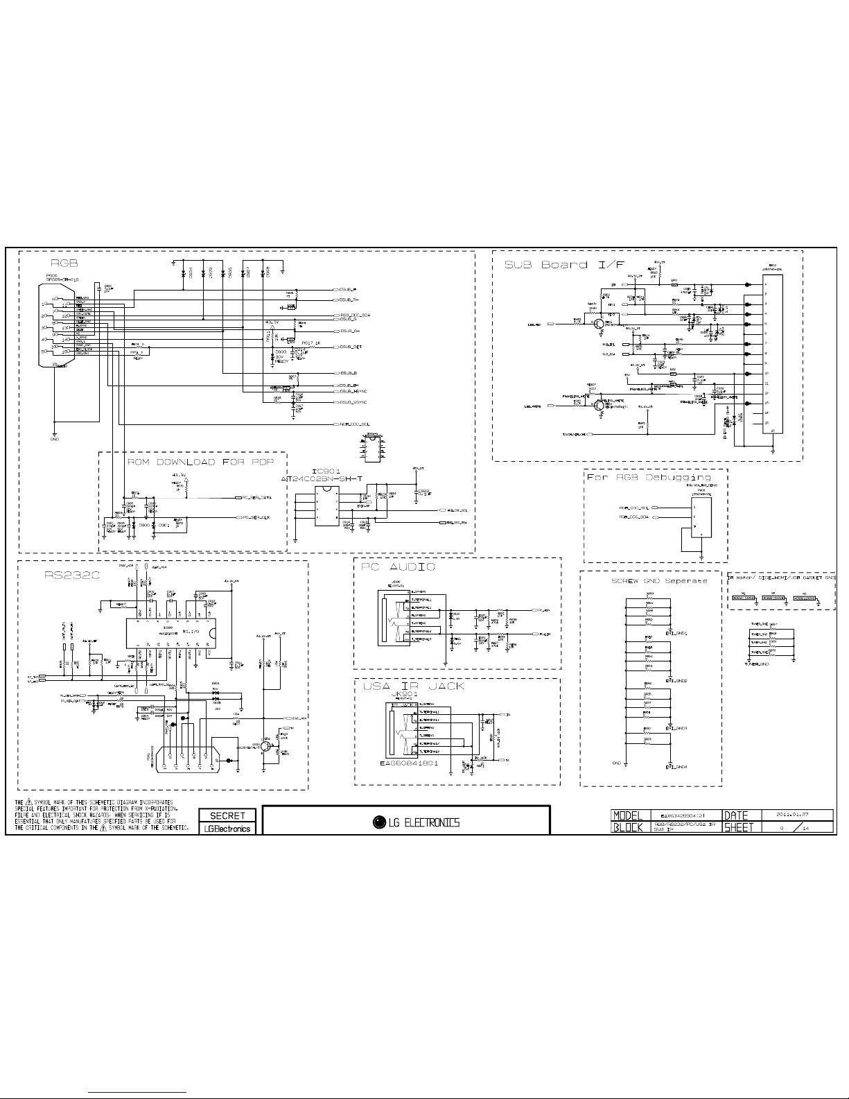
SCHEMATIC CIRCUIT DIAGRAM ..............................................................................................
- 3 -
LGE Internal Use OnlyCopyright ©2011 LG Electronics Inc. All rights reserved.
Only for training and service purposes
SAFETY PRECAUTIONS
Many electrical and mechanical parts in this chassis have special safety-related characteristics. These parts are identified by in
the Schematic Diagram and Exploded View.
It is essential that these special safety parts should be replaced with the same components as recommended in this manual to
prevent X-RADIATION, Shock, Fire, or other Hazards.
Do not modify the original design without permission of manufacturer.
General Guidance
An isolation Transformer should always be used during the
servicing of a receiver whose chassis is not isolated from the AC
power line. Use a transformer of adequate power rating as this
protects the technician from accidents resulting in personal injury
from electrical shocks.
It will also protect the receiver and it's components from being
damaged by accidental shorts of the circuitry that may be
inadvertently introduced during the service operation.
If any fuse (or Fusible Resistor) in this monitor is blown, replace it
with the specified.
When replacing a high wattage resistor (Oxide Metal Film
Resistor, over 1W), keep the resistor 10mm away from PCB.
Keep wires away from high voltage or high temperature parts.
Due to high vacuum and large surface area of picture tube,
extreme care should be used in handling the Picture Tube.
Do not lift the Picture tube by it's Neck.
Leakage Current Cold Check(Antenna Cold Check)
With the instrument AC plug removed from AC source, connect
an electrical jumper across the two AC plug prongs. Place the
AC switch in the on position, connect one lead of ohm-meter to
the AC plug prongs tied together and touch other ohm-meter
lead in turn to each exposed metallic parts such as antenna
terminals, phone jacks, etc.
If the exposed metallic part has a return path to the chassis, the
measured resistance should be between 1MΩ and 5.2MΩ.
When the exposed metal has no return path to the chassis the
reading must be infinite.
An other abnormality exists that must be corrected before the
receiver is returned to the customer.
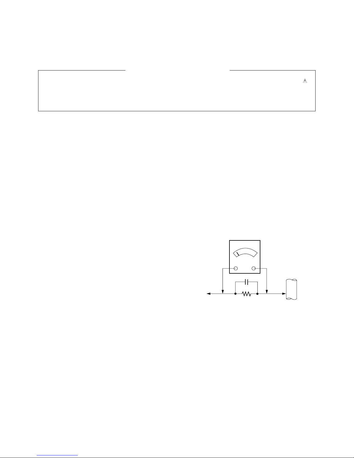
Leakage Current Hot Check (See below Figure)
Plug the AC cord directly into the AC outlet.
Do not use a line Isolation Transformer during this check.
Connect 1.5K/10watt resistor in parallel with a 0.15uF capacitor
between a known good earth ground (Water Pipe, Conduit, etc.)
and the exposed metallic parts.
Measure the AC voltage across the resistor using AC voltmeter
with 1000 ohms/volt or more sensitivity.
Reverse plug the AC cord into the AC outlet and repeat AC
voltage measurements for each exposed metallic part. Any
voltage measured must not exceed 0.75 volt RMS which is
corresponds to 0.5mA.
In case any measurement is out of the limits specified, there is
possibility of shock hazard and the set must be checked and
repaired before it is returned to the customer.
Leakage Current Hot Check circuit
1.5 Kohm/10W
To Instrument’s
exposed
METALLIC PARTS
Good Earth Ground
such as WATER PIPE,
CONDUIT etc.
AC Volt-meter
IMPORTANT SAFETY NOTICE
0.15uF
- 4 -
LGE Internal Use OnlyCopyright ©2011 LG Electronics Inc. All rights reserved.
Only for training and service purposes
SPECIFICATION
NOTE : Specifications and others are subject to change without notice for improvement
.
1. Application Range
(1) This spec sheet is applied all of PDP TV with PU11A chassis.
2. Specification
Each part is tested as below without special appointment.
(1) Temperature : 25 °C ± 5 °C (77 °F ± 9 °F), CST : 40 °C ± 5 °C
(2) Relative Humidity : 65 % ± 10 %
(3) Power Voltage : Standard input voltage (100 V - 240 V ~ 50 / 60 Hz)
* Standard Voltage of each product is marked by models
(4) Specification and performance of each parts are followed each drawing and specification by part number in accordance with
BOM.
(5) The receiver must be operated for about 5 minutes prior to the adjustment.
3. Test Method
(1) Performance : LGE TV test method followed.
(2) Demanded other specification
Safety : UL, CSA, IEC specification, CE
EMC : FCC, ICES, IEC specification, CE
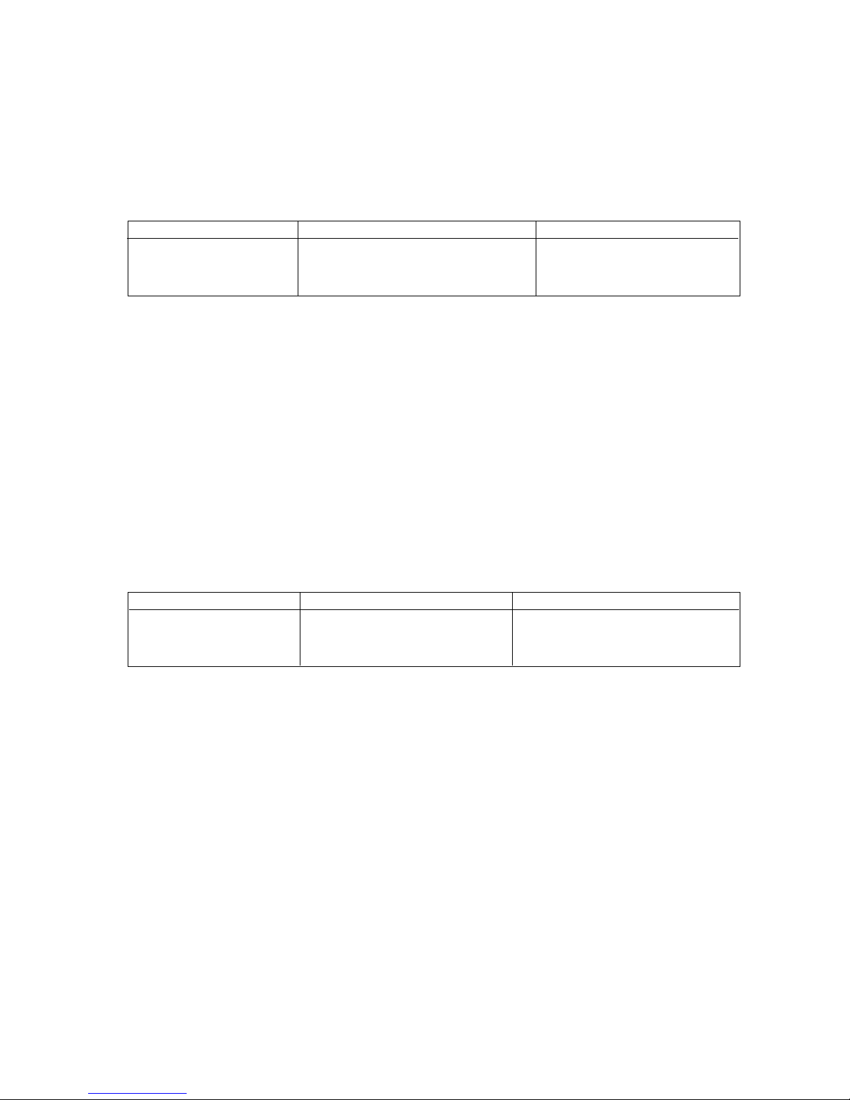
Model Name Market Brand
42PW340-UB
42PW350-UA/UE North America / Canada / Maxico LG
42PW350U-UC
Model Name Market Appliance
42PW340-UB Safety : UL1492, USA C22.2 No. 1
42PW350-UA/UE North America / Canada / Maxico EMC : FCC Class B, IC Class B
42PW350U-UC
- 5 -
LGE Internal Use OnlyCopyright ©2011 LG Electronics Inc. All rights reserved.
Only for training and service purposes
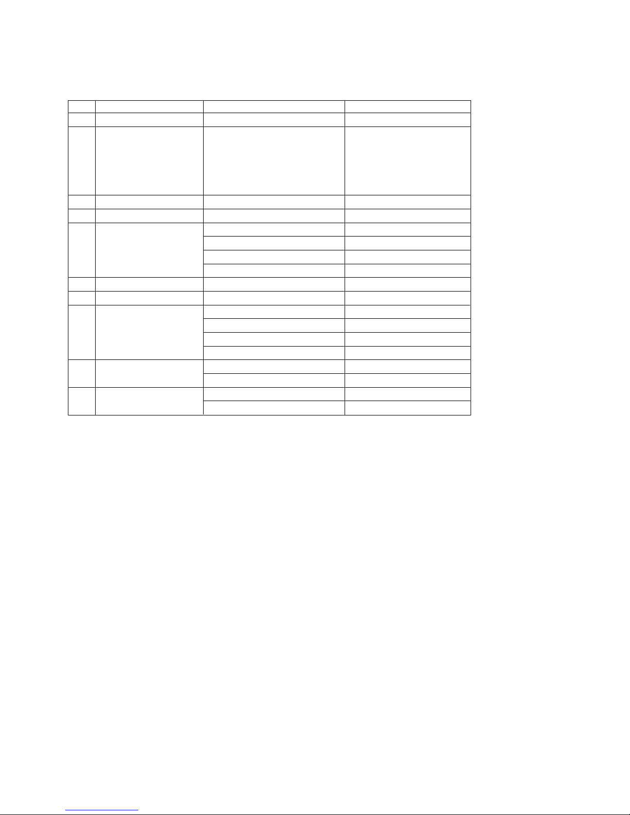
4. General Specification
No Item Specification Remark
1. Receiving System 1) ATSC / NTSC-M
2. Available Channel 1) VHF : 02~13
2) UHF : 14~69
3) DTV : 02-69
4) CATV : 01~135
5) CADTV : 01~135
3. Input Voltage 1) AC 100 ~ 240V 50/60Hz N.America Mark : 110V, 60Hz
4. Market NORTH AMERICA ,KOREA
5. Screen Size 42 inch Wide(1024 × 768) 42PW340-UA
50 inch Wide(1024 × 768) 50PW340-UA / 50PW350-UB
50 inch Wide(1920 × 1080) 50PZ250-UA
60 inch Wide(1920 × 1080) 60PZ250-UA
6. Aspect Ratio 16:9
7. Tuning System FS
8. Module PDP42T3#### (1024 × 768) 42PW340-UA
PDP50T3#### (1024 × 768) 50PW340-UA / 50PW350-UB
PDP50R303## (1920 × 1080) 50PZ250-UA
PDP60R103## (1920 × 1080) 60PZ250-UA
9. Operating Environment 1) Temp : 0 ~ 40 deg
2) Humidity : ~ 80 %
10. Storage Environment 1) Temp : -20 ~ 60 deg
2) Humidity : ~ 85 %

- 6 -
LGE Internal Use OnlyCopyright ©2011 LG Electronics Inc. All rights reserved.
Only for training and service purposes
ADJUSTMENT INSTRUCTION
1. Application Range
This spec. sheet applies to PU11A Chassis applied PDP TV
all models manufactured in TV factory.
2. Specification
(1) Because this is not a hot chassis, it is not necessary to use
an isolation transformer. However, the use of isolation
transformer will help protect test instrument.
(2) Adjustment must be done in the correct order. But it is
flexible when its factory local problem occurs.
(3) The adjustment must be performed in the circumstance of
25 cC ± 5 cC of temperature and 65 % ± 10 % of relative
humidity if there is no specific designation.
(4) The input voltage of the receiver must keep 100 V - 240 V,
50 / 60 Hz.
(5) Before adjustment, execute Heat-Run for 5 minutes.
V After Receive 100% Full white pattern (06CH) then
process Heat-run
(or “8. Test pattern” condition of Ez-Adjust status)
V How to make set white pattern
1) Press Power ON button of Service Remocon
2) Press ADJ button of Service remocon. Select “10.
Test pattern” and, after select “White” using
navigation button, and then you can see 100% Full
White pattern.
* In this status you can maintain Heat-Run useless any
pattern generator
* Notice: if you maintain one picture over 20 minutes
(Especially sharp distinction black with white pattern –
13Ch, or Cross hatch pattern – 09Ch) then it can
appear image stick near black level.
3. Adjustment items
3-1. PCB Assembly adjustment
(1) Adjust 480i Comp1
(2) Adjust 1080p Comp1/RGB
- If it is necessary, it can adjustment at Manufacture Line
- You can see set adjustment status at “9. ADJUST
CHECK” of the “In-start menu”
3-2. Set Assembly Adjustment
(1) EDID (The Extended Display Identification Data )
(2) Color Temperature (White Balance) Adjustment
(3) Make sure RS-232C control
(4) Selection Factory output option
4. PCB Assembly Adjustment
4-1. Using RS-232C
- Adjust 3 items at 3-1 PCB assembly adjustments
“ (3) Adjustment sequence” one after the order.
(1) Adjustment protocol
(2) Necessary items before Adjustment items
O Pattern Generator : (MSPG-925FA)
O Adjust 480i Comp1
(MSPG-925FA:model :209, pattern :65) – Comp1 Mode
O Adjust 1080p Comp1
(MSPG-925FA:model :225 , pattern :65) – Comp1 Mode
O Addjust RGB (MSPG-925FA:model :225 , pattern :65)
– RGB-PC Mode
* If you want more information then see the below Adjustment
method (Factory Adjustment)
(3) Adjustment sequence
O aa 00 00: Enter the ADC Adjustment mode.
O xb 00 40: Change the mode to Component1 (No actions)
O ad 00 10: Adjust 480i Comp
O ad 00 10: Adjust 1080p comp
O xb 00 60: Change to RGB-PC mode(No action)
O ad 00 10: Adjust 1080p RGB
O xb 00 90: Endo of Adjustmennt
< See ADC Adjustment RS232C Protocol_Ver1.0 >
Order Command Set response
1. Inter the aa 00 00 a 00 OK00x
Adjustment
mode
2. Change the XB 00 40 b 00 OK40x (Adjust 480i Comp1 )
Source XB 00 60 (Adjust 1080p Comp1)
b 00 OK60x (Adjust 1080p RGB)
3. Start ad 00 10
Adjustment
4. Return the OKx ( Success condition )
Response NGx ( Failed condition )
5. Read data ( main ) (main : component1 480i, RGB 1080p)
Adjustment ad 00 20 00000000000000000000000007c007b006dx
data ( main ) (main : component1 480i, RGB 1080p)
ad 00 30 000000070000000000000000007c00830077x
6. Confirm ad 00 99 NG 03 00x (Failed condition)
Adjustment NG 03 01x (Failed condition)
NG 03 02x (Failed condition)
OK 03 03x (Success condition)
7. End of ad 00 90 d 00 OK90x
Adjustment

5. Factory Adjustment
PU11A : USE INTERNAL ADC(S7R) : using internal pattern.
5-1. Auto Adjust Component
480i/1080p RGB 1080p
(1) Summary : Adjustment component 480i/1080i and RGB
1080p is Gain and Black level setting at Analog
to Digital converter, and compensate the RGB
deviation
(2) Using instrument
1) Adjustment remocon, 801GF(802B, 802F, 802R) or
MSPG925FA pattern generator
(It can output 480i/1080i horizontal 100 % color bar
pattern signal, and its output level must setting
0.7 V ± 0.1 V p-p correctly)
* You must make it sure its resolution and pattern cause every
instrument can have different setting
2) Adjustment method 480i Comp1, Adjust 1080p
Comp1/RGB (Factory adjustment)
O ADC 480i Component1 adjustment -
- Check connection of Component1
- MSPG-925FA Ë Model: 209, Pattern 65
O Set Component 480i mode and 100% Horizontal
Color Bar Pattern(HozTV31Bar), then set TV set to
Component1 mode and its screen to “NORMAL”
O ADC 1080p Component1 / RGB adjustment
- Check connection both of Component1 and RGB
- MSPG-925FA Ë Model: 225, Pattern 65
O Set Component 1080p mode and 100% Horizontal
Color Bar Pattern(HozTV31Bar), then set TV set to
Component1 mode and its screen to “NORMAL”
O After get each the signal, wait more a second and
enter the “IN-START” with press IN-START key of
Service remocon. After then select “7. External ADC”
with navigator button and press “Enter”.
O After Then Press key of Service remocon “Right
Arrow(VOL+)”
O You can see “ADC Component1 Success”
O Component1 1080p, RGB 1080p Adjust is same
method.
O Component 1080p Adjustment in Component1 input
mode
O RGB 1080p adjustment in RGB input mode
O If you success RGB 1080p Adjust. You can see “ADC
RGB-DTV Success”
Caution : Set Volume 0 after adjustment
5-2. Use Internal ADC(S7R)
- ADJ(EZ ADJUST) -> 6.ADC Calibration -> ADC
Calibration(START)
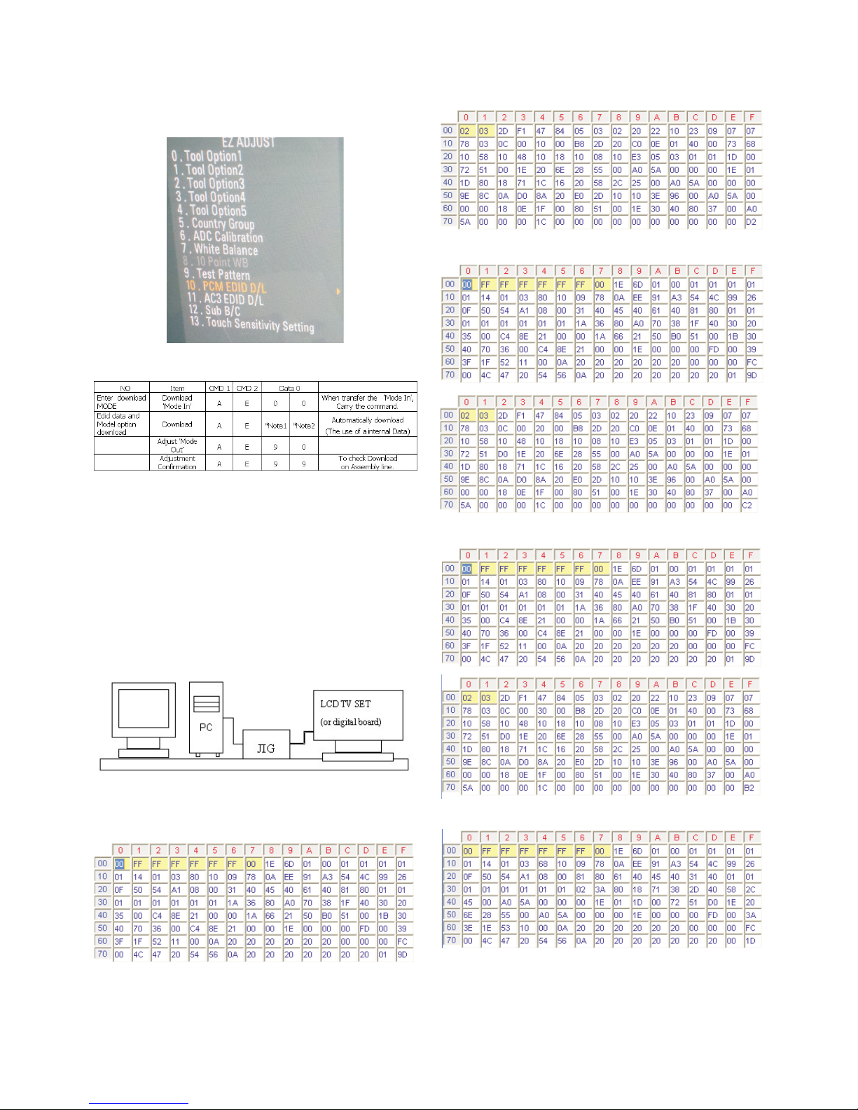
5-3. EDID(The Extended Display
Identification Data) / DDC(Display Data
Channel) download
(1) Summary
1) It is established in VESA, for communication between
PC and Monitor without order from user for building user
condition. It helps to make easily use realize “Plug and
Play” function.
2) For EDID data write, we use DDC2B protocol.
5-4. Auto Download
(1) After enter Service Mode by pushing “ADJ” key,
(2) Enter EDID D/L mode.
(3) Enter “START” by pushing “OK” key.
Caution
- Never connect HDMI & D-sub Cable when the user
downloading .
- Use the proper cables below for EDID Writing.
- 7 -
LGE Internal Use OnlyCopyright ©2011 LG Electronics Inc. All rights reserved.
Only for training and service purposes
< Adjustment pattern : 480i / 1080p 60Hz Pattern >
- 8 -
LGE Internal Use OnlyCopyright ©2011 LG Electronics Inc. All rights reserved.
Only for training and service purposes
O It only needs to PCM EDID D/L for North America Product.
(42PW350-UA)
* Edid data and Model option download(RS232)
5-5. Manual Download
(1) Write HDMI EDID data
1) Using instruments
- Jig. (PC Serial to D-Sub connection) for PC, DDC
adjustment.
- S/W for DDC recording (EDID data write and read)
- D-sub jack
- Additional HDMI cable connection Jig.
2) Preparing and setting.
- Set instruments and Jig. Like pic.5), then turn on PC
and Jig.
- Operate DDC write S/W (EDID write & read)
- It will operate in the DOS mode.
EDID DATA (Model name = LG TV)
- HDMI1 EDID table(3D HD) US(PCM)
- HDMI2 EDID table(3D HD) US(PCM)
- HDMI3 EDID table(3D HD) US(PCM)
- RGB EDID table(3D HD) US (PCM)
< For write EDID data, setting Jig and another instruments >

- 9 -
LGE Internal Use OnlyCopyright ©2011 LG Electronics Inc. All rights reserved.
Only for training and service purposes
- HDMI1 EDID table(3D HD) US(AC3)
- HDMI2 EDID table(3D HD) US(AC3)
- HDMI3 EDID table(3D HD) US(AC3)
- RGB table(3D HD) US (AC3)
* See Working Guide if you want more information about EDID
communication.
5-6. Adjustment Color Temperature
(White balance)
(1) Using Instruments
1) Color Analyzer: CA-210 (CH 9)
- Using LCD color temperature, Color Analyzer (CA-
210) must use CH 9, which Matrix compensated
(White, Red, Green, Blue compensation) with CS-
2100. See the Coordination bellowed one.
2) Auto-adjustment Equipment (It needs when Autoadjustment – It is availed communicate with RS-232C :
Baud rate: 115200)
3) Video Signal Generator MSPG-925F 720p, 216Gray
(Model: 217, Pattern 78)
(2) Connection Diagram (Auto Adjustment)
1) Using Inner Pattern
2) Using HDMI input
< Connection Diagram for Adjustment White balance >
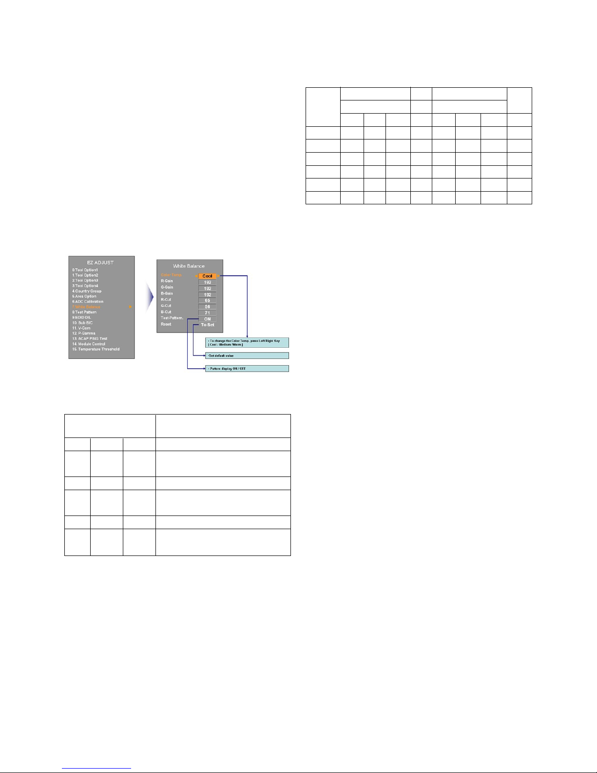
(3) White Balance Adjustment
- If you can’t adjust with inner pattern, then you can adjust
it using HDMI pattern. You can select option at “Ez-Adjust
Menu – 7. White Balance” there items “NONE, INNER,
HDMI”. It is normally setting at inner basically. If you can’t
adjust using inner pattern you can select HDMI item, and
you can adjust.
- In manual Adjust case, if you press ADJ button of service
remocon, and enter “Ez-Adjust Menu – 7. White Balance”,
then automatically inner pattern operates. (In case of
“Inner” originally “Test-Pattern. On” will be selected in The
“Test-Pattern. On/Off”.
O Connect all cables and equipments like Pic.5)
O Set Baud Rate of RS-232C to 115200. It may set
115200 orignally.
O Connect RS-232C cable to set
O Connect HDMI cable to set
V RS-232C COMMAND(Commonly apply)
O wb 00 00”: Start Auto-adjustment of white balance.
O “wb 00 10”: Start Gain Adjustment (Inner pattern)
O “jb 00 c0” :
O …
O “wb 00 1f”: End of Adjustment
* If it needs, offset adjustment (wb 00 20-start, wb 00 2f-
end)
O “wb 00 ff”: End of white balance adjustment (inner
pattern disappear)
V Adjustment Mapping information
O When Color temperature (White balance) Adjustment
(Automatically)
- Press “Power only key” of service remocon and
operate automatically adjustment.
- Set BaudRate to 115200.
O You must start “wb 00 00” and finish it “wb 00 ff”.
O If it needs, then adjustment “Offset”.
(4) White Balance Adjustment (Manual adjustment)
1) Test Equipment: CA-210
- Using PDP color temperature, Color Analyzer (CA-
210) must use CH 10, which Matrix compensated
(White, Red, Green, Blue compensation) with CS-
2100. See the Coordination bellowed one.
2) Manual adjustment sequence is like bellowed one.
- Turn to “Ez-Adjust” mode with press ADJ button of
service remocon.
- Select “10.Test Pattern” with CH+/- button and press
enter. Then set will go on Heat-run mode. Over 30
minutes set let on Heat-run mode.
- Let CA-210 to zero calibration and must has gap more
10cm from center of PDP module when adjustment.
- Press “ADJ” button of service remocon and select
“7.White-Balance” in “Ez-Adjust” then press “
G” button
of navigation key. (When press “
G” button then set will
go to full white mode)
- Adjust at three mode (Cool, Medium, Warm)
- If “cool” mode
Let B-Gain to 192 and R, G, B-Cut to 64 and then
control R, G gain adjustment High Light adjustment.
- If “Medium” and “Warm” mode Let R-Gain to 192 and
R, G, B-Cut to 64 and then control G, B gain
adjustment High Light adjustment.
- All of the three mode
Let R-Gain to 192 and R, G, B-Cut to 64 and then
control G, B gain adjustment High Light adjustment.
- With volume button (+/-) you can adjust.
- After all adjustment finished, with Enter (_ key) turn to
Ez-Adjust mode. Then with ADJ button, exit from
adjustment mode
- 10 -
LGE Internal Use OnlyCopyright ©2011 LG Electronics Inc. All rights reserved.
Only for training and service purposes
RS-232C COMMAND
[CMD ID DATA] Meaning
wb 00 00 White Balance adjustment start.
wb 00 10 Start of adjust gain
(Inner white pattern)
wb 00 1f End of gain adjust
wb 00 20 Start of offset adjust
(Inner white pattern)
wb 00 2f End of offset adjust
wb 00 ff End of White Balance adjust
(Inner pattern disappeared)
RS-232C COMMAND
CENTER
[CMD ID DATA] MIN (DEFAULT) MAX
Cool Mid Warm Cool Mid Warm
R Gain jg Ja jd 00 184 192 192 192
G Gain jh Jb je 00 187 183 159 192
B Gain ji Jc jf 00 192 161 95 192
R Cut 64 64 64 127
G Cut 64 64 64 127
B Cut 64 64 64 127

* Attachment: White Balance adjustment coordination and color
temperature.
O Using CS-1000 Equipment.
- COOL : T=11000K, _uv=0.000, x=0.276 y=0.283
- MEDIUM : T=9300K, _uv=0.000, x=0.285 y=0.293
- WARM : T=6500K, _uv=0.000, x=0.313 y=0.329
O Using CA-210 Equipment. (10 CH)
- Contras value : 216 Gray
- Brighness spec.
6. Test of RS-232C control.
- Press In-Start button of Service Remocon then set the “4.Baud
Rate” to 115200. Then check RS-232C control and
7. Selection of Country option.
- Selection of country option is allowed only North American
model (Not allowed Korean model). It is selection of Country
about Rating and Time Zone.
(1) Models: All models which PB82C Chassis (See the first
page.)
(2) Press “In-Start” button of Service Remocon, then enter the
“Option” Menu with “PIP CH-“ Button
(3) Select one of these three (USA, CANADA, MEXICO)
defends on its market using “Vol. +/-“button.
Caution : Don’t push The INSTOP KEY after completing the
function inspection
Caution : Inspection only PAL M / NTSC
8. GND and ESD Testing
8-1. Prepare GND and ESD Testing.
- Check the connection between set and power cord
8-2. Operate GND and ESD auto-test.
(1) Fully connected (Between set and power cord) set enter
the Auto-test sequence.
(2) Connect D-Jack AV jack test equipment.
(3) Turn on Auto-controller(GWS103-4)
(4) Start Auto GND test.
(5) If its result is NG, then notice with buzzer.
(6) If its result is OK, then automatically it turns to ESD Test.
(7) Operate ESD test
(8) If its result is NG, then notice with buzzer.
(9) If its result is OK, then process next steps. Notice it with
Good lamp and STOPER Down.
8-3. Check Items.
(1) Test Voltage
GND: 1.5KV/min at 100mA
Signal: 3KV/min at 100mA
(2) Test time: just 1 second.
(3) Test point
- GND test: Test between Power cord GND and Signal
cable metal GND.
- ESD test: Test between Power cord GND and Live and
neutral.
(4) Leakage current: Set to 0.5mA(rms)
9. POWER PCB Ass’y Voltage
Adjustment
(Va/Vs Voltage Adjustment)
(1)Test equipment : D.M.M 1EA
(2) Connection Diagram for Measuring : refer to fig.1
- 11 -
LGE Internal Use OnlyCopyright ©2011 LG Electronics Inc. All rights reserved.
Only for training and service purposes
Color Test Color Coordination
temperature Equipment x y
COOL CA-210 0.276±0.002 0.283±0.002
MEDIUM CA-210 0.285±0.002 0.293±0.002
WARM CA-210 0.313±0.002 0.329±0.002
Item Min Typ Max Unit Remark
White 49 60 - cd/m - 100%Window White
average Pattern
brightness - 100IRE(255Gray)
- Picture: Vivid(Medium )
Brightness -20 +20 % - 85IRE(216Gray) 100%
uniformity Window White Pattern
- Picture: Vivid(Medium)
< fig.1 : 42 inch Power PCB Assy Voltage adjustment >
9-1. Adjustment method
(1) Vs adjustment (refer fig.1)
1) Connect + terminal of D.M.M. to Vs pin of P811, connect
-terminal to GND pin of P811
2) After turning VR901, voltage of D.M.M adjustment as
same as Vs voltage which on label of panel left/top (
deviation ; ±0.5V)
(2) Va adjustment (refer fig.1)
1) After receiving 100% Full White Pattern, HEAT RUN.
2) Connect + terminal of D.M.M. to Va pin of P811, connect
-terminal to GND pin of P811.
3) After turning VR502,voltage of D.M.M adjustment as
same as Va voltage which on label of panel left/top
(deviation; ±0.5V)
10. Default Service option.
10-1. ADC-Set.
V R-Gain adjustment Value (default 128)
V G-Gain adjustment Value (default 128)
V B-Gain adjustment Value (default 128)
V R-Offset adjustment Value (default 128)
V G-Offset adjustment Value (default 128)
V B-Offset adjustment Value (default 128)
10-2. White balance. Value.
10-3. Temperature Threshold
V Threshold Down Low 20
V Threshold Up Low 23
V Threshold Down High 70
V Threshold Up High 75
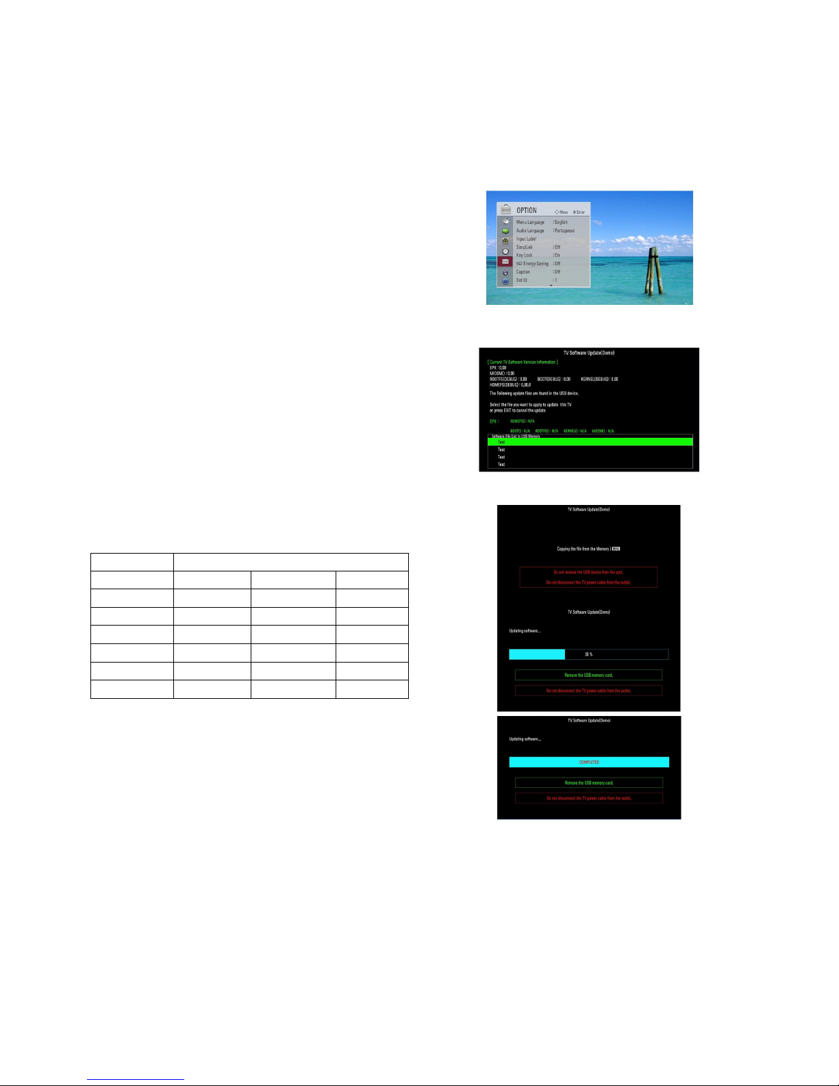
11. USB DOWNLOAD
(*.epk file download)
V Put the USB Stick to the USB socket
V Press Menu key, and move OPTION
V Press “FAV” Press 7 times.
V Select download file (epk file)
V After download is finished, remove the USB stick.
V Press “IN-START” key of ADJ remote control, check the
S/W version.
CAUTION
- DO NOT REMOVE USB MEMORY CARD FROM USB PORT
WHEN YOU FIND BELOW DESCRIPTION
- " Do not remove the memory card from the port! "
- 12 -
LGE Internal Use OnlyCopyright ©2011 LG Electronics Inc. All rights reserved.
Only for training and service purposes
CENTER (DEFAULT)
Cool Mid Warm
R Gain 192 192 192
G Gain 192 192 192
B Gain 192 192 192
R Cut 64 64 64
G Cut 64 64 64
B Cut 64 64 64
- 13 -
LGE Internal Use OnlyCopyright ©2011 LG Electronics Inc. All rights reserved.
Only for training and service purposes
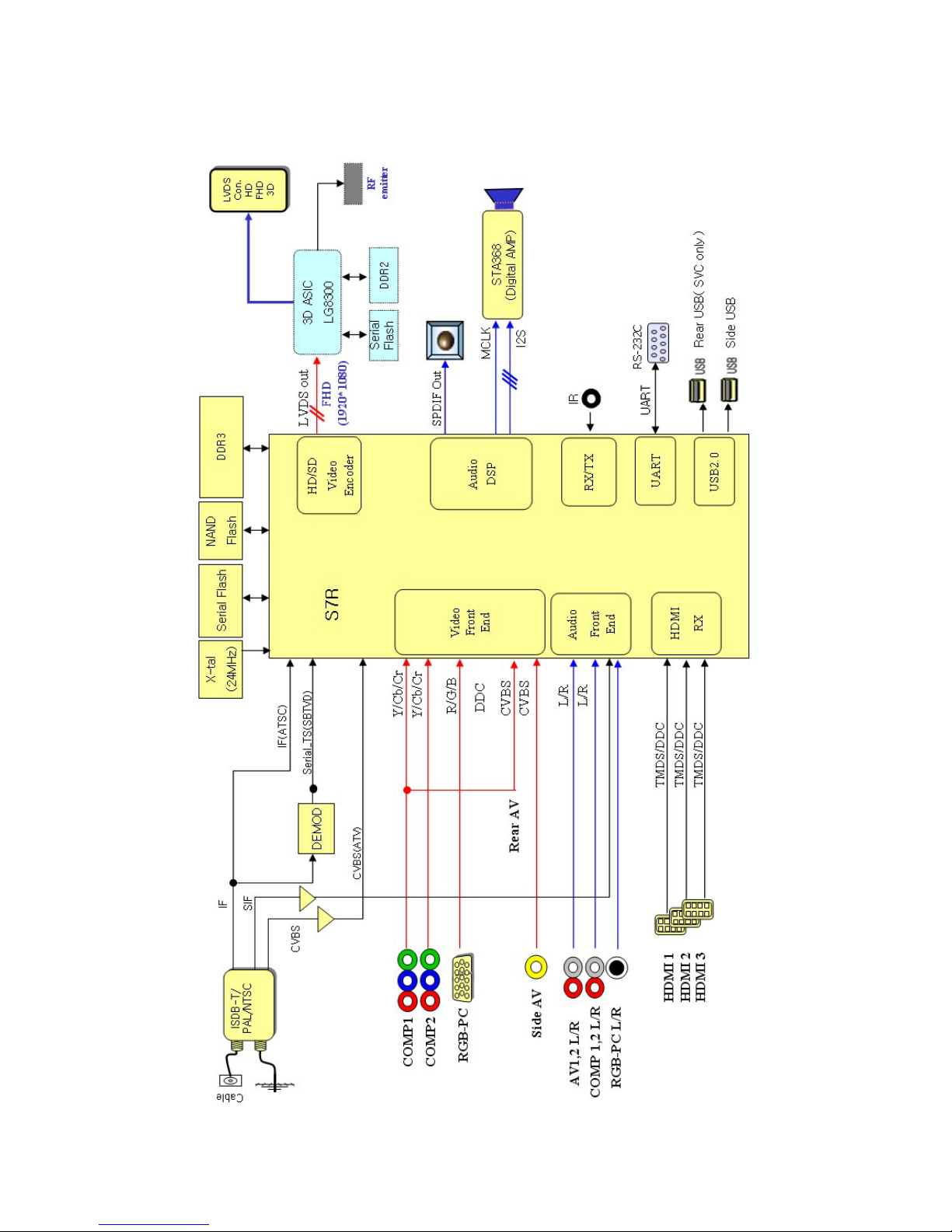
BLOCK DIAGRAM

- 14 -
LGE Internal Use Only
EXPLODED VIEW
900
910
203
590
204
601
207
520
400
200
240
580
301
305
120
300
206
202
205
302
303
304
501
602
201
570
560
Many electrical and mechanical parts in this chassis have special safety-related characteristics. These
parts are identified by in the Schematic Diagram and EXPLODED VIEW.
It is essential that these special safety parts should be replaced with the same components as
recommended in this manual to prevent X-RADIATION, Shock, Fire, or other Hazards.
Do not modify the original design without permission of manufacturer.
IMPORTANT SAFETY NOTICE
A10
A9
LV1
A12
A21
A2
A4

Copyright © 2011 LG Electronics Inc. All rights reserved.
Only for training and service purposes
LGE Internal Use Only
Copyright © 2011 LG Electronics Inc. All rights reserved.
Only for training and service purposes
LGE Internal Use Only
Copyright © 2011 LG Electronics Inc. All rights reserved.
Only for training and service purposes
LGE Internal Use Only
Copyright © 2011 LG Electronics Inc. All rights reserved.
Only for training and service purposes
LGE Internal Use Only
Copyright © 2011 LG Electronics Inc. All rights reserved.
Only for training and service purposes
LGE Internal Use Only
Copyright © 2011 LG Electronics Inc. All rights reserved.
Only for training and service purposes
LGE Internal Use Only
Copyright © 2011 LG Electronics Inc. All rights reserved.
Only for training and service purposes
LGE Internal Use Only
Copyright © 2011 LG Electronics Inc. All rights reserved.
Only for training and service purposes
LGE Internal Use Only
 Loading...