

LG 42PT85 Owner's Manual
Please read this manual carefully before operating your
TV.
Retain it for future reference.
Record model number and serial number of the TV.
Refer to the label on the back cover and quote this
information.
To y our dealer when requiring service.
LCD TV PLASMA TV
OWNER’S MANUAL
LCD TV MODELS
3322LLTT77
**
3377LLTT77
**
4422LLTT77
**
PLASMA TV MODELS
4422PPTT88
**
5500PPTT88
**
ENGLISH
Tr ademark of the DVB Digital Video
Broadcasting Project (1991 to 1996)
IIDD NNuummbbeerr((ss)) ::
4652: 42PT85 4651: 50PT85
4681: 32LT75 4680: 37LT75
4679: 42 LT75

1
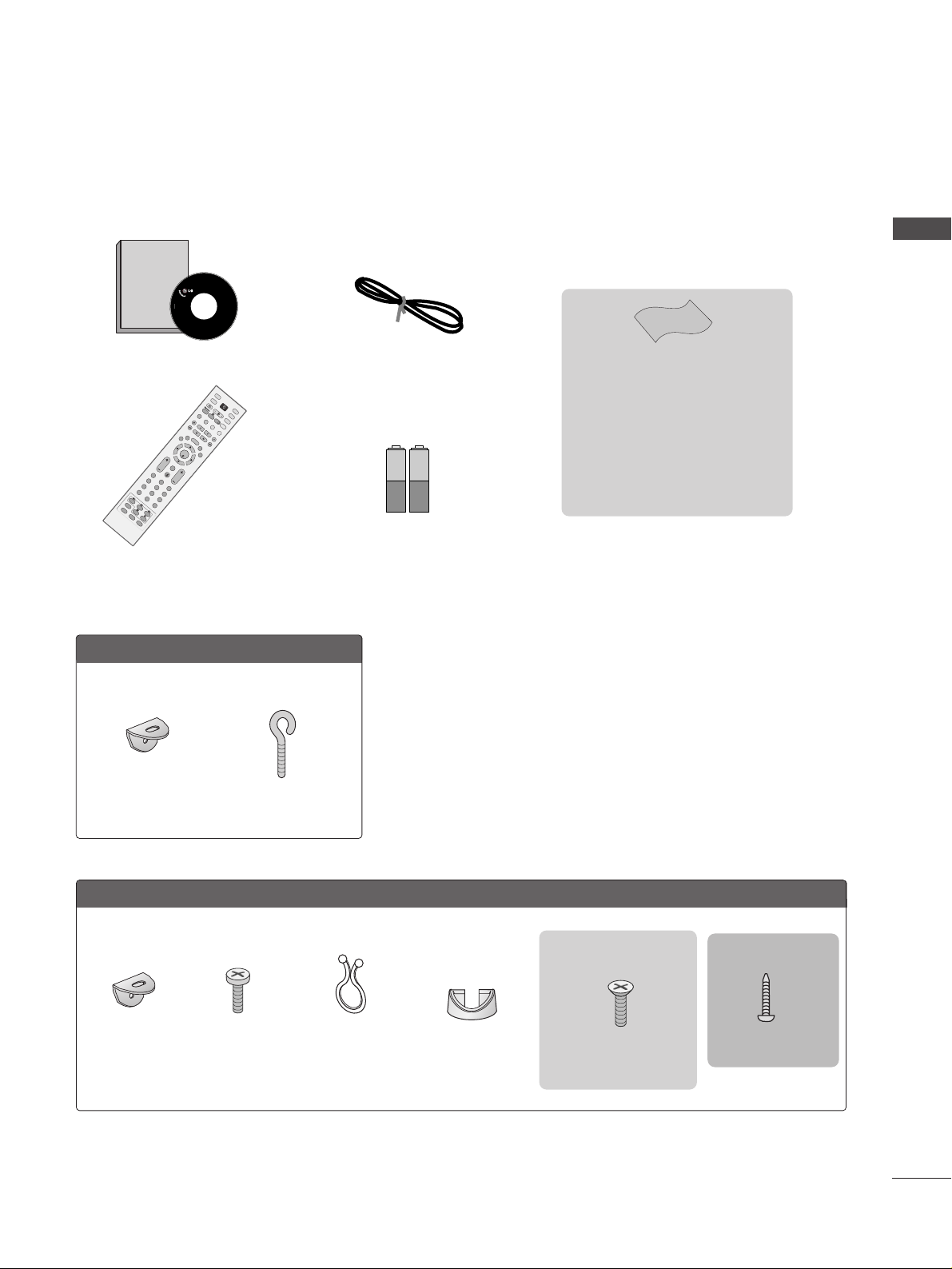
ACCESSORIES
ACCESSORIES
Ensure that the following accessories are included with your TV. If an accessory is missing, please contact the
dealer where you purchased the TV.
Owner's
Manual
Owner’s manual
Owner’s Manual
Batteries
OK
IN
P
U
T
M
O
D
E
TV
D
/
A
D
V
D
E
X
I
T
T
I
M
E
S
H
I
F
T
T
I
M
E
S
H
I
F
T
V
O
L
P
R
GUIDE
B
A
C
K
M
E
N
U
D
VR
L
I
V
E
T
V
V
C
R
PO
W
E
R
123
456
789
0
Q.VIEW
L
IS
T
INDEX
S
L
E
E
P
H
O
L
D
R
E
V
E
A
L
?
S
U
B
T
IT
L
E
R
A
T
I
O
T
E
X
T
I
N
P
U
T
BRIGHT
M
U
T
E
M
A
R
K
TV/RAD
IO
U
P
D
A
T
E
S
IM
P
L
IN
K
IN
F
O
i
F
A
V
T
I
M
E
I
/
I
I
Remote Control
Power Cord
Cable Management
2- TV Brackets
2- Wall Brackets
This feature is not
available for all models.
2-bolts
This feature is not
available
for all models.
Twister Holder
Arrange the wires with
the twister holder.
This feature is not available
for all models.
LLCCDD TTVV mmooddeellss
PPllaassmmaa TTVV mmooddeellss
4-bolts for stand assembly
Refer to p. 9
33 22””,, 3377 ”” oonn ll yy
2-Wall brackets
This feature is not available
for all models.
2-eye-bolts
This feature is not available
for all models.
Polishing Cloth
Polishing cloth for use on the screen
This feature is not available
for all models.
*Lightly wipe any stains or fingerprints on
the surface of the TV with the polishing
cloth.
Do not use excessive force. This may
cause scratching or discolouration.
33 22//3377LLTT77**oonn llyy
1-screw for stand fixing
Refer to p. 9

2
CONTENTS
ACCESSORIES
. . . . . . . . . . . . . . . . . . . . . . . . . . . . . . . . . . . . . . . . . . . . .
1
PREPARATION
Home Menu . . . . . . . . . . . . . . . . . . . . . . . . . . . . . . . 4
Front Panel Controls . . . . . . . . . . . . . . . . . . . . . . . . 5
Back Panel Information . . . . . . . . . . . . . . . . . . . . . . 7
Stand installation . . . . . . . . . . . . . . . . . . . . . . . . . . . . 9
AT TA CHING THE TV TO A DESK (Only 32/37LT7*model) . . .9
Attaching the TV to a wall . . . . . . . . . . . . . . . . . . . . 10
Back Cover for Wire Arrangement . . . . . . . . . . . . . 11
Desktop Pedestal Installation . . . . . . . . . . . . . . . . . 13
Wall Mount: Horizontal installation . . . . . . . . . . . . 13
Antenna Connection . . . . . . . . . . . . . . . . . . . . . . . . 14
EXTERNAL EQUIPMENT SETUP
HD Receiver Setup . . . . . . . . . . . . . . . . . . . . . . . . 15
DVD Setup . . . . . . . . . . . . . . . . . . . . . . . . . . . . . . . . 17
Insertion of CI module . . . . . . . . . . . . . . . . . . . . . . 19
VCR Setup . . . . . . . . . . . . . . . . . . . . . . . . . . . . . . . . 20
Digital Audio Out Setup . . . . . . . . . . . . . . . . . . . . . 22
Other A/V Source Setup . . . . . . . . . . . . . . . . . . . . 23
PC Setup . . . . . . . . . . . . . . . . . . . . . . . . . . . . . . . . . 24
- Screen Setup for PC Mode . . . . . . . . . . . . . . . 27
WATCHING TV / PROGRAMME CONTROL
Remote Control Key Functions . . . . . . . . . . . . . . . . 31
Turning on the TV . . . . . . . . . . . . . . . . . . . . . . . . . . 33
Programme Selection . . . . . . . . . . . . . . . . . . . . . . . 34
Volume Adjustment . . . . . . . . . . . . . . . . . . . . . . . . 34
On-Screen Menus Selection and Adjustment . . . . 35
Auto Programme Tuning (In Digital Mode) . . . . . . 36
Manual Programme Tuning (In Digital Mode) . . . . 37
Programme Edit (In Digital Mode) . . . . . . . . . . . . . 38
5V antenna Power (In Digital Mode only) . . . . . . . 40
Booster (In Digital Mode only) . . . . . . . . . . . . . . . 40
Software Update (In Digital Mode only) . . . . . . . . 41
Diagnostics (In Digital Mode only) . . . . . . . . . . . . 42
CI Information (In Digital Mode only) . . . . . . . . . . 43
Auto Programme Tuning (In Analogue Mode) . . . . . 44
Manual Programme Tuning (In Analogue Mode)
. . . . . . . 45
Fine Tuning (In Analogue Mode) . . . . . . . . . . . . . . 46
Assigning a Station Name (In Analogue Mode)
. . . . . . 46
Programme Edit (In Analogue Mode)
. . . . . . . . . . . . . 47
Selecting the Programme Table . . . . . . . . . . . . . . 49
Input Source Selection . . . . . . . . . . . . . . . . . . . . . 50
SIMPLINK Function . . . . . . . . . . . . . . . . . . . . . . . . . 51
DVR (DIGITAL VIDEO RECORDER)
TimeShift Mode ( Pause & Replay of Live TV) . . . 53
Instant Recording . . . . . . . . . . . . . . . . . . . . . . . . . . 56
Manual Recording
. . . . . . . . . . . . . . . . . . . . . . . . . . 59
Recorded TV Programme List . . . . . . . . . . . . . . . . . 60
Schedule List . . . . . . . . . . . . . . . . . . . . . . . . . . . . . . 64
Record Quality . . . . . . . . . . . . . . . . . . . . . . . . . . . . 65
Format Hard Disc . . . . . . . . . . . . . . . . . . . . . . . . . . 66
EPG (Electronic programme guide)(In Digital Mode)
Switch on/off EPG . . . . . . . . . . . . . . . . . . . . . . . . 67
Select programme . . . . . . . . . . . . . . . . . . . . . . . . 67
Button function in NOW/NEXT guide mode . . . 67
Button function in 8 days guide mode . . . . . . . . 68
Button function in date change mode . . . . . . . . 69
Button function in extended description box . . . 69
Record Popup . . . . . . . . . . . . . . . . . . . . . . . . . . . .70
Conflict pop-up . . . . . . . . . . . . . . . . . . . . . . . . . .70
PICTURE CONTROL
Picture Size (Aspect Ratio) Control . . . . . . . . . . . . 71
Preset Picture Settings
- Picture Mode-Preset . . . . . . . . . . . . . . . . . . . . 73
-
Auto Colour Tone Control (Warm/Medium/Cool)
. . . . .74
Manual Picture Adjustment
- Picture Mode-User option . . . . . . . . . . . . . . . . 75
- Colour Tone - User option . . . . . . . . . . . . . . . .76
CONTENTS

3
CONTENTS
XD - Picture Improvement Technology . . . . . . . . . . . . . 77
XD Demo . . . . . . . . . . . . . . . . . . . . . . . . . . . . . . . . . 78
Advanced - Cinema . . . . . . . . . . . . . . . . . . . . . . . . . 79
Advanced - Black(Darkness) Level . . . . . . . . . . . . . 80
Picture Reset . . . . . . . . . . . . . . . . . . . . . . . . . . . . . . 81
Image Sticking Minimization(ISM) Method . . . . . . . . . . 82
Low-Power Picture Mode . . . . . . . . . . . . . . . . . . . . 83
SOUND & LANGUAGE CONTROL
Auto Volume Leveler . . . . . . . . . . . . . . . . . . . . . . . . 84
Preset Sound Settings - Sound Mode . . . . . . . . . . 85
Sound Setting Adjustment - User Mode . . . . . . . . . . 86
Balance . . . . . . . . . . . . . . . . . . . . . . . . . . . . . . . . . . . 87
TV Speakers On/ Off Setup . . . . . . . . . . . . . . . . . . 88
Selecting digital audio out . . . . . . . . . . . . . . . . . . . 89
I/II
-
Stereo/Dual Reception (In Analogue Mode Only)
. . . . 90
-
NICAM Reception (In Analogue Mode Only) . . . . . . .
91
- Speaker Sound Output Selection . . . . . . . . . . 91
On-Screen Menus Language/Country Selection
. . . . . . . 92
Language selection (In Digital Mode only) . . . . . . 93
TIME SETTING
Clock Setup . . . . . . . . . . . . . . . . . . . . . . . . . . . . . . . 94
Auto On/ Off Timer Setting . . . . . . . . . . . . . . . . . . 95
Auto Shut-off Setting . . . . . . . . . . . . . . . . . . . . . . . 96
Time zone Setup . . . . . . . . . . . . . . . . . . . . . . . . . . . 97
Sleep Timer Setting . . . . . . . . . . . . . . . . . . . . . . . . . 97
PARENTAL CONTROL / RATINGS
Set Password & Lock System . . . . . . . . . . . . . . . . . 98
Parental Control . . . . . . . . . . . . . . . . . . . . . . . . . . . 99
TELETEXT
Switch on/off . . . . . . . . . . . . . . . . . . . . . . . . . . . . . 100
SIMPLE Text . . . . . . . . . . . . . . . . . . . . . . . . . . . . . . 100
TOP Text . . . . . . . . . . . . . . . . . . . . . . . . . . . . . . . . 100
FAS TEXT . . . . . . . . . . . . . . . . . . . . . . . . . . . . . . . . 101
Special Teletext Functions . . . . . . . . . . . . . . . . . . . 101
DIGITAL TELETEXT
Teletext within Digital Service . . . . . . . . . . . . . . 102
Teletext in Digital Service . . . . . . . . . . . . . . . . . 102
APPENDIX
Tr oubleshooting . . . . . . . . . . . . . . . . . . . . . . . . . . . 103
Maintenance . . . . . . . . . . . . . . . . . . . . . . . . . . . . . 105
Product Specifications . . . . . . . . . . . . . . . . . . . . . 106
Programming the Remote Control . . . . . . . . . . . . 107
IR Codes . . . . . . . . . . . . . . . . . . . . . . . . . . . . . . . . 109
External Control Device Setup . . . . . . . . . . . . . . . 111
4
PREPARATION
PREPARATION
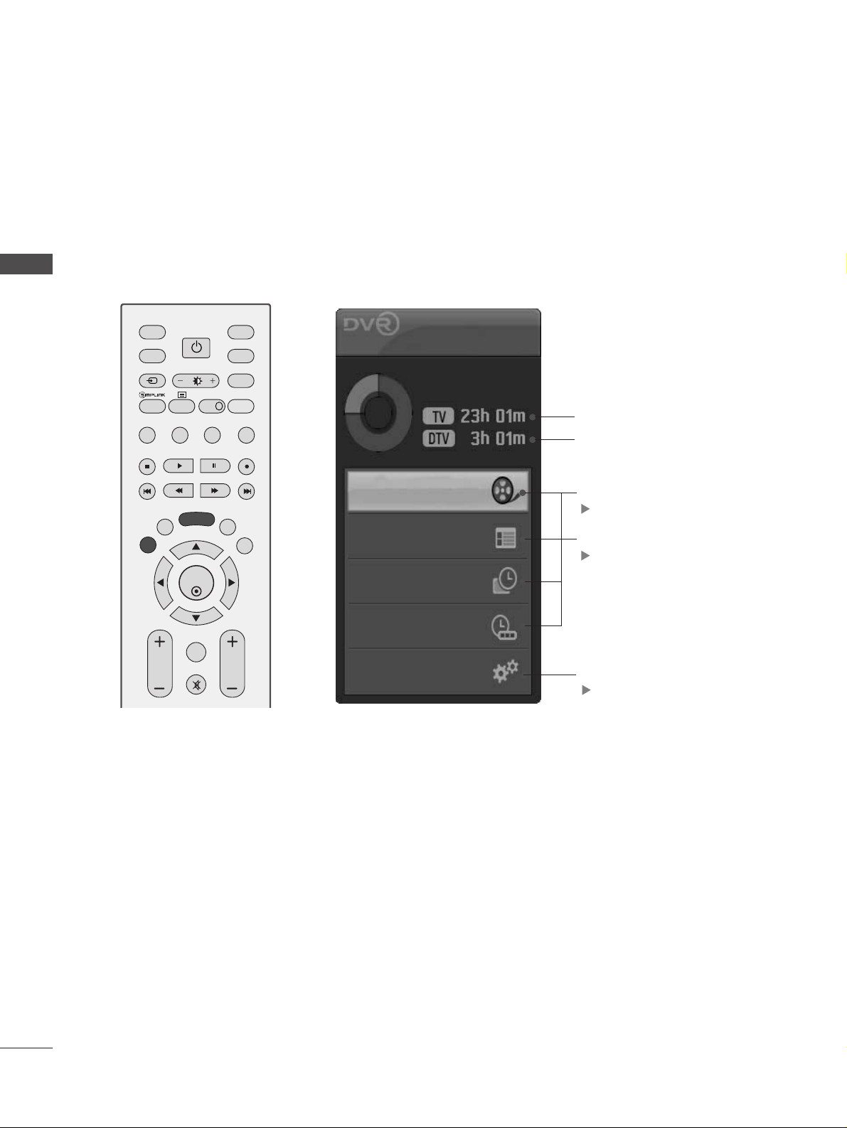
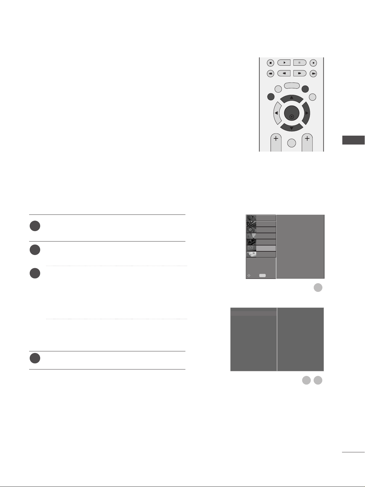
HOME MENU
This menu is a contents guide.
In the Home Menu, you can access the Recorded list of the DVR, Manual Recording of the DVR,
Schedule List or the TV Menu.
OK
INPUT MODE
TV
D/A
DVD
EXIT
TIME
SHIFT
TIME
SHIFT
VOL PR
GUIDE
BACK MENU
DVR
LIVE TV
VCR
POWER
TEXT
INPUT
BRIGHT
MUTE
MARK
TV/RADIO
SIMPLINK
INFO i
FAV
Home
Free Space
Programme Guide
Recorded TV
Schedule List
Manual Record
TV Menu
DVR
pp..5533
EPG
pp..6677
TV Menu
pp..3355
This displays the remaining record
time for analogue input. (Analog
TV, AV1,AV2, AV3)
This displays the remaining
record time for DTV input.
5
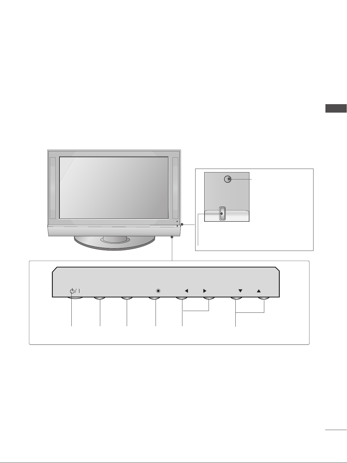
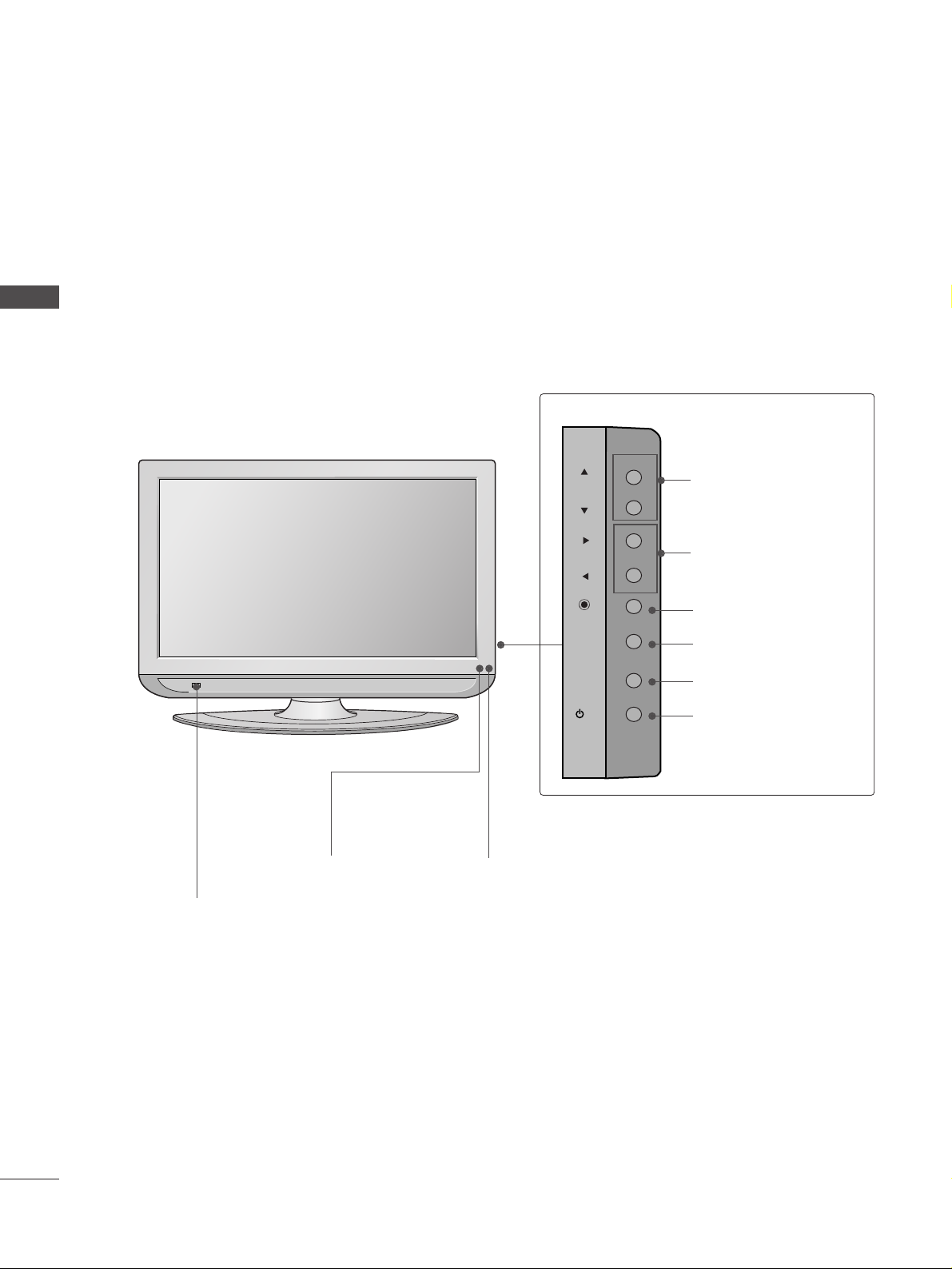
FRONT PANEL CONTROLS
A
This is a simplified representation of the front panel. Image shown may differ from your TV.
A
If your TV has a protection film attached, remove the film and then wipe the TV with a polishing cloth.
PREPARATION
PROGRAMME
VOLUME
MENU
OK
INPUT
POWER
Plasma TV Models
Remote Control Sensor
Power/Standby Indicator
• illuminates red in standby mode.
• illuminates green when the TV is switched on.
INPUT
MENU
OK
VOL
PR
6
PREPARATION
PREPARATION
LCD TV Models
Remote Control Sensor
Power/Standby Indicator
• illuminates red in standby mode.
• illuminates green when the TV is switched on.
PROGRAMME
VOLUME
OK
MENU
INPUT
POWER
Intelligent Eye
Adjusts picture
according to the
surrounding conditions.
PR
VOL
OK
MENU
INPUT
/I
7
USB
AV IN 2
L/MONO
R
AUDIO
VIDEO
S-VIDEO
Plasma TV Models
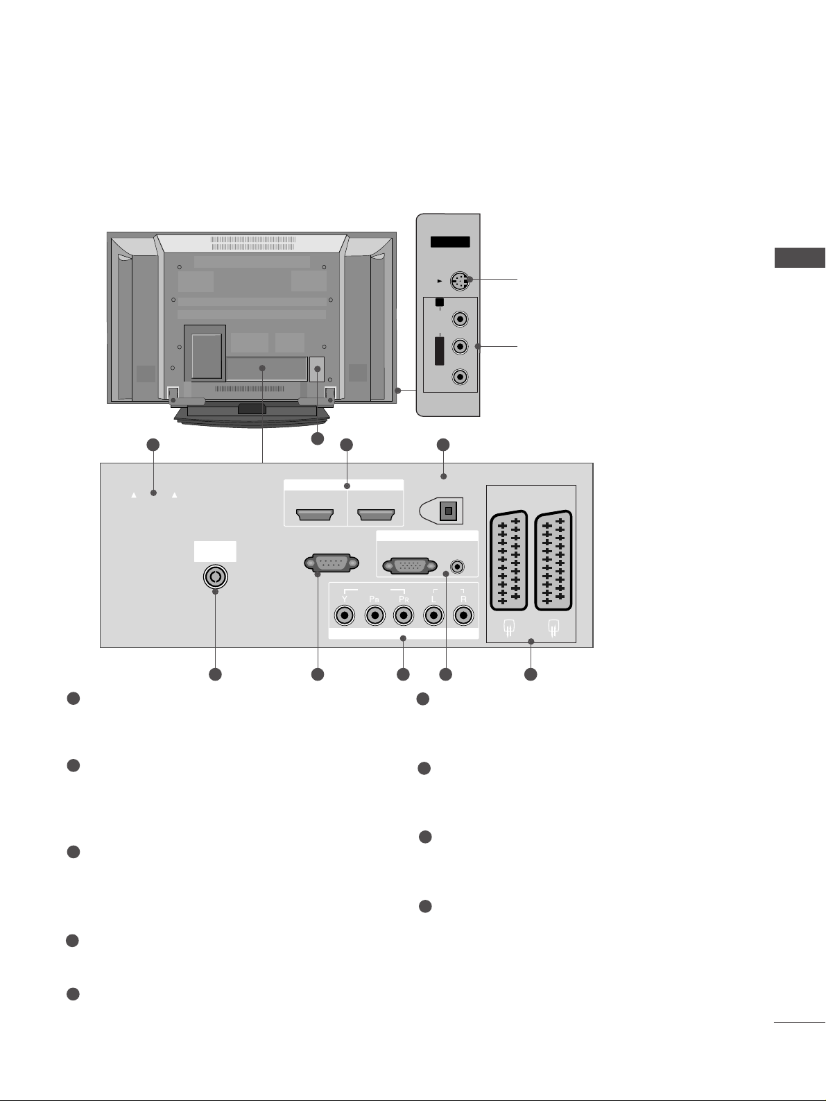
S-Video Input
Connect S-Video out from an
S-VIDEO device.
Audio/Video Input
Connect audio/video output
from an external device to
these jacks.
AV IN 3V IN 3
L/L/MONOMONO
R
AUDIOAUDIO
VIDEOVIDEO
S-VIDEOS-VIDEO
AV IN 3
L/MONO
R
AUDIO
VIDEO
S-VIDEO
AUDIO
VIDEO
V 1
V 2
EJECT
PCMCIA
CARD SLOT
RS-232C IN
1 32
9
PCMCIA (Personal Computer Memory Card
International Association) Card Slot
(This feature is not available in all countries.)
HDMI Input
Connect a HDMI signal to HDMI IN.
Or DVI(VIDEO)signal to HDMI/DVI port with DVI
to HDMI cable.
DIGITAL AUDIO OUT (OPTICAL)
Connect digital audio from various types of equipment.
Note: In standby mode, these ports do not work.
Antenna Input
Connect RF antenna (UHF) to this jack.
RS-232C IN (CONTROL & SERVICE) PORT
Connect to the RS-232C port on a PC.
Component Input
Connect a component video/audio device to
these jacks.
RGB/DVI Audio Input
Connect the monitor output from a PC to the
appropriate input port.
Euro Scart Socket (AV1/AV2)
Connect scart socket input or output from an
external device to these jacks.
Power Cord Socket
This TV operates on an AC power. The voltage is
indicated on the Specifications page. Never
attempt to operate the TV on DC power.
1
2
3
4
5
6
7
8
9
84 5 6 7
BACK PANEL INFORMATION
A
This is a simplified representation of the back panel. Image shown may differ from your TV.
PREPARATION
EJECT
PCMCIA
CARD SLOT
ANTENNA
IN
HDMI/DVI IN
12
RS-232C IN
(CONTROL & SERVICE)
HDMI IN
VIDEO
COMPONENT IN
DIGITAL AUDIO OUT
(OPTICAL)
RGB IN
RGB(PC)
AUDIO
(RGB/DVI)
AUDIO
AV 1
AV 2
8
PREPARATION
PREPARATION
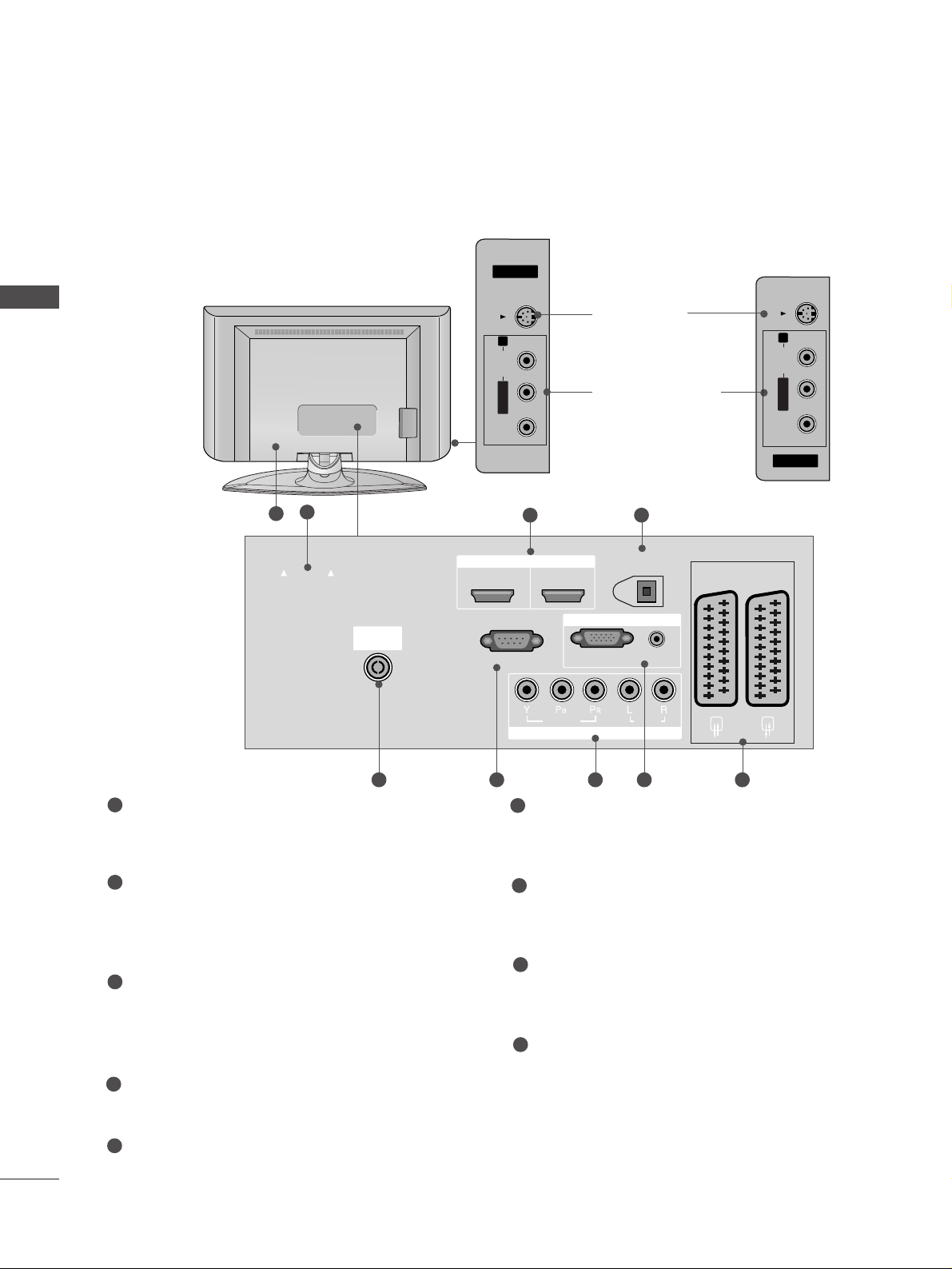
LCD TV Models
AV IN 3
L/MONO
R
AUDIO
VIDEO
S-VIDEO
AV IN 3
L/MONO
R
AUDIO
VIDEO
S-VIDEO
AV IN 3
L/MONO
R
AUDIO
VIDEO
S-VIDEO
AV IN 3
L/MONO
R
AUDIO
VIDEO
S-VIDEO
AUDIO
VIDEO
V 1
V 2
EJECT
PCMCIA
CARD SLOT
RS-232C IN
1
9
32
84 5 6 7
PCMCIA (Personal Computer Memory Card
International Association) Card Slot
(This feature is not available in all countries.)
HDMI Input
Connect a HDMI signal to HDMI IN.
Or DVI(VIDEO)signal to HDMI/DVI port with DVI
to HDMI cable.
DIGITAL AUDIO OUT (OPTICAL)
Connect digital audio from various types of equipment.
Note: In standby mode, these ports do not work.
Antenna Input
Connect RF antenna (UHF) to this jack.
RS-232C IN (CONTROL & SERVICE) PORT
Connect to the RS-232C port on a PC.
Component Input
Connect a component video/audio device to
these jacks.
RGB/DVI Audio Input
Connect the monitor output from a PC to the
appropriate input port.
Euro Scart Socket (AV1/AV2)
Connect scart socket input or output from an
external device to these jacks.
Power Cord Socket
This TV operates on an AC power. The voltage is
indicated on the Specifications page. Never
attempt to operate the TV on DC power.
1
2
3
4
5
6
7
8
9
S-Video Input
Connect S-Video out
from an S-VIDEO device.
Audio/Video Input
Connect audio/video
output from an external
device to these jacks.
3322LLTT77
**
AV IN 3V IN 3
L/L/MONOMONO
R
AUDIOAUDIO
VIDEOVIDEO
S-VIDEOS-VIDEO
3377LLTT77
**
4422LLTT77
**
AV IN 3V IN 3
L/L/MONOMONO
R
AUDIOAUDIO
VIDEOVIDEO
S-VIDEOS-VIDEO
PCMCIA
CARD SLOT
EJECT
ANTENNA
IN
HDMI/DVI IN
12
RS-232C IN
(CONTROL & SERVICE)
HDMI IN
DIGITAL AUDIO OUT
(OPTICAL)
RGB IN
RGB(PC)
AUDIO
(RGB/DVI)
AV 1
AV 2
VIDEO
COMPONENT IN
AUDIO
9
PREPARATION
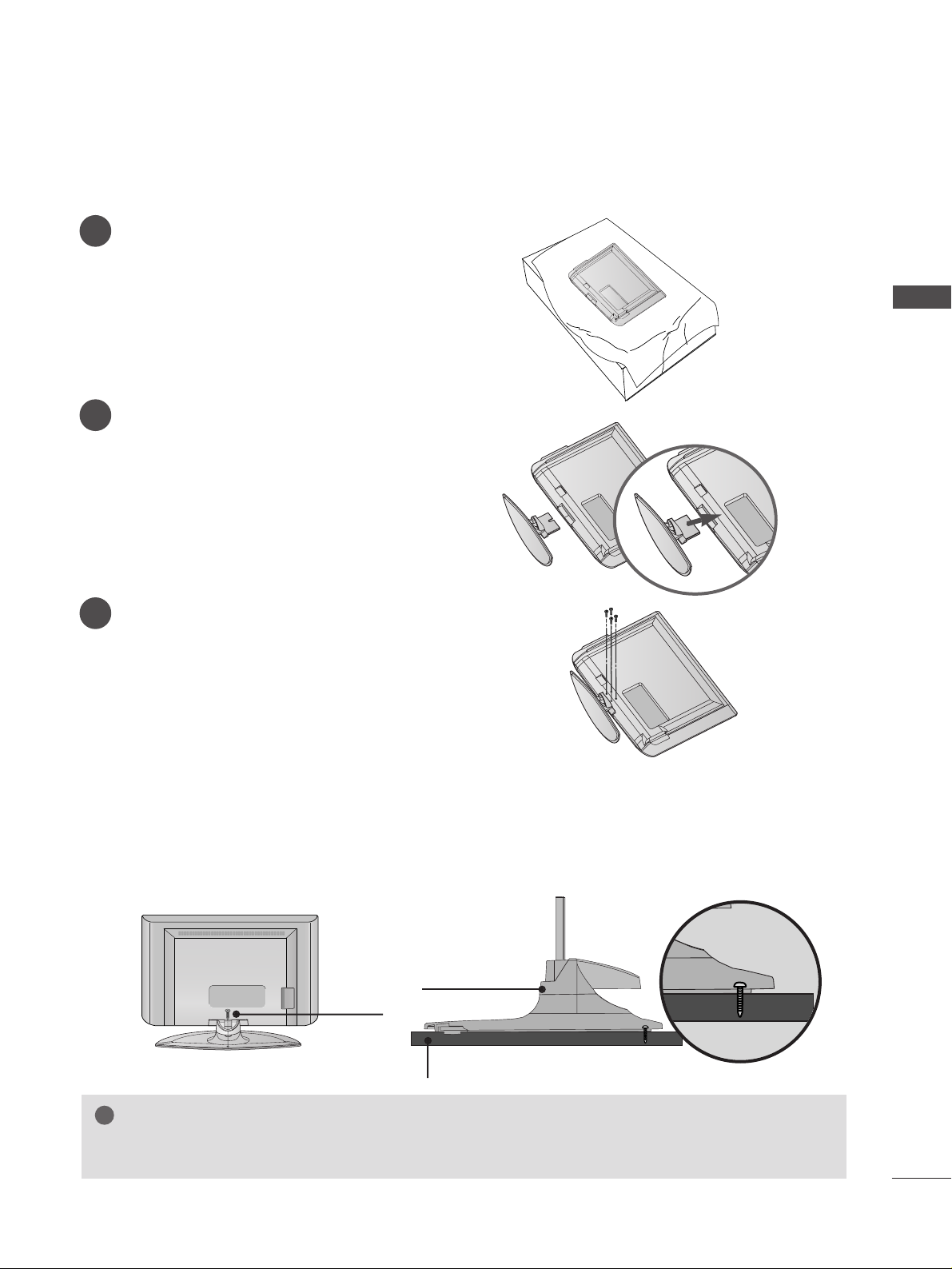
STAND INSTALLATION (Only 32, 37 inch LCD TV Models)
1
2
3
Carefully place the TV screen side down on a
cushioned surface to protect the screen from
damage.
Assemble the TV as shown.
Fix the 4 bolts securely using the holes in the
back of the TV.
ATTA CHING THE TV TO A DESK (Only 32/37LT7
*
model)
The TV must be attached to desk so it cannot be pulled in a forward/backward direction, potentially causing
injury or damaging the product. Use only an attached screw.
1-Screw
Stand
Desk
WARNING
!
GG
To prevent TV from falling over, the TV should be securely attached to the floor/wall per
installation instructions. Tipping, shaking, or rocking the machine may cause injury.
10
PREPARATION
PREPARATION
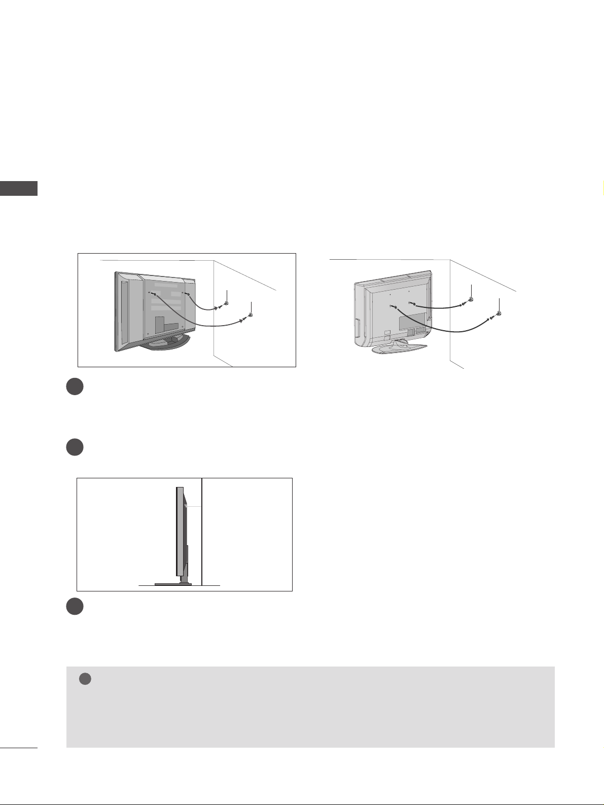
ATTA CHING THE TV TO A WALL
(This feature is not available for all models.)
or
2
1
■
Position the TV close to the wall to avoid the possibility of it falling when pushed.
■
The instructions shown below are a safer way to
set up the TV, which is to fix it to the wall, avoiding the
possibility of it falling forwards if pulled. This will prevent the TV from falling forward and causing injury.
This will also prevent the TV from damage. Ensure that children do not climb or hang from the TV.
NOTE
!
G
When moving the TV undo the cords first.
G
Use a platform or cabinet string and large enough to support the size and weight of the TV.
G
To use the TV safely make sure that the height of the bracket on the wall and on the TV is the same.
3
1
2
Use the eye-bolts or TV brackets/bolts to fix the TV to the wall as shown in the picture.
(If your TV has bolts in the eyebolts, loosen then bolts.)
* Insert the eye-bolts or TV brackets/bolts and tighten them securely in the upper holes.
Secure the wall brackets with bolts (must purchase seperately) to the wall.
Ensure that both brackets are even.
3
Use a strong cord (must purchase separately) to secure the TV.
Secure the cord in such a way that it becomes taught when the TV is in position.
2
1
11
PREPARATION
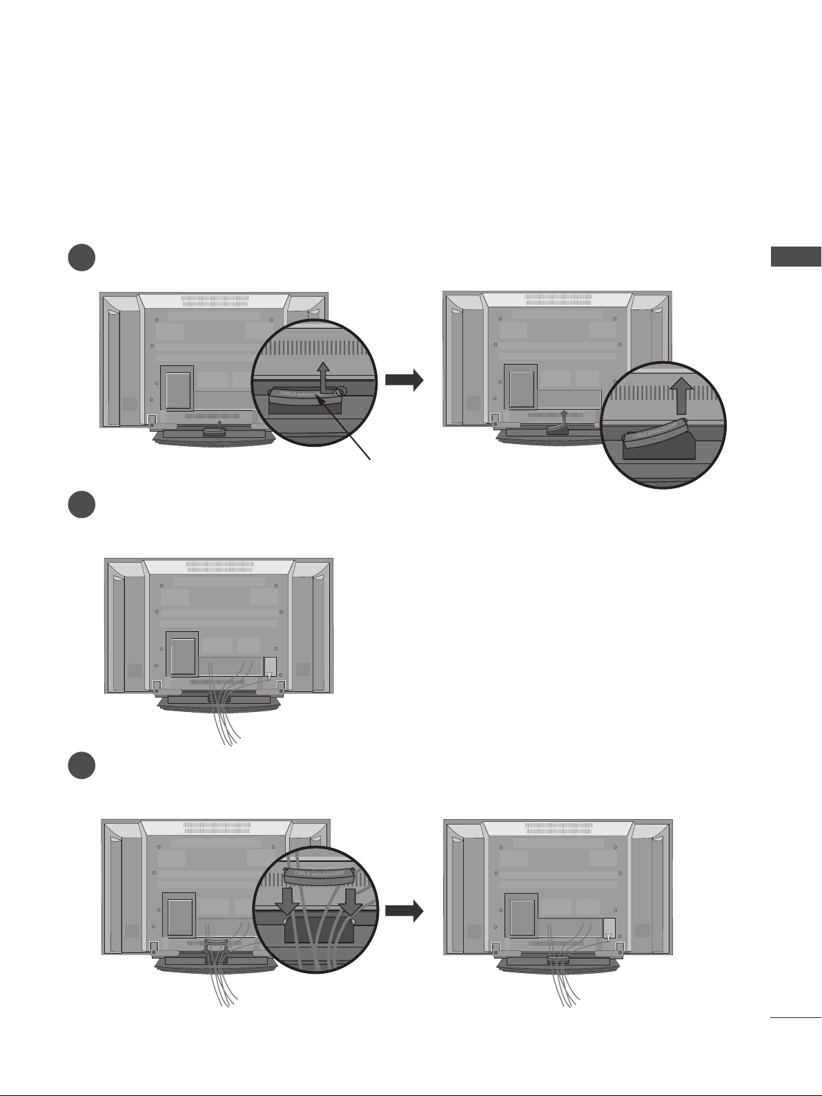
BACK COVER FOR WIRE ARRANGEMENT
Plasma TV models
Connect the cables as necessary.
To connect additional equipment, see the External equipment Setup section of the manual.
Reinstall the
CC AABBLLEE MMAANN AAGGEEMMEENN TT
as shown.
2
1
3
Grip the CABLE MANAGEMENT and push the cover upwards.
CABLE MANAGEMENT
12
PREPARATION
PREPARATION
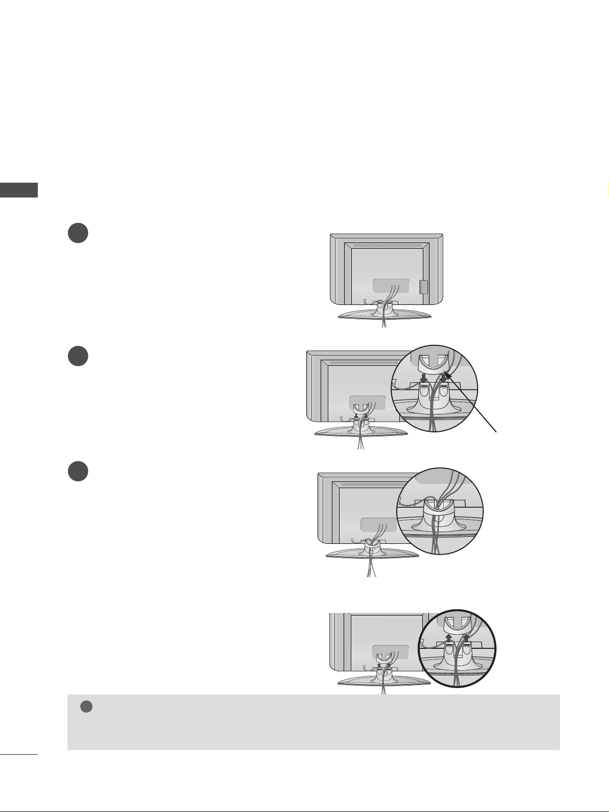
LCD TV models
Connect the cables as necessary.
To connect additional equipment, see the
External equipment Setup section.
1
Install the
CC AABBLLEE MMAANN AAGGEEMMEENN TT
as shown.
2
Bundle the cables using the supplied twister
holder.
(This feature is not available for all models.)
3
Hold the
CC AABBLL EE MMAANN AAGG EEMM EENNTT
with both
hands and pull it upward.
NOTE
!
GG
Do not use the CABLE MANAGEMENT to lift the TV.
- If the TV is dropped, you may be injured or the TV may be damaged.
How to remove the cable management
CABLE MANAGEMENT
13
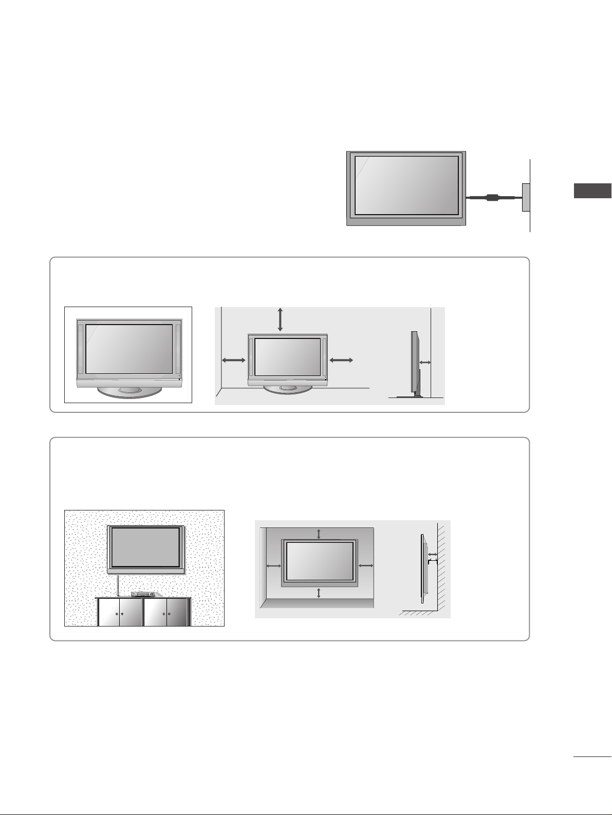
Desktop Pedestal Installation
For adequate ventilation allow a clearance of 4” (10cm) all around the TV .
Wall Mount: Horizontal installation
For adequate ventilation allow a clearance of 4” (10cm) all around the TV. Detailed installation instructions
are available from your dealer, see the optional Tilt Wall Mounting Bracket Installation and Setup Guide.
EARTHING
Ensure that you connect the earth wire to prevent possible
electric shock. If grounding methods are not possible, have
a qualified electrician install a separate circuit breaker. Do
not try to earth the TV by connecting it to telephone wires,
lightening rods or gas pipes.
Power Supply
Circuit
breaker
■
The TV can be installed in various ways such as on a wall, or on a desktop etc.
■
The TV is designed to be mounted horizontally.
4 inches
4 inches 4 inches 4 inches
4 inches
4 inches
4 inches 4 inches
4 inches
PREPARATION
14
PREPARATION
PREPARATION
AV 3
L/MONO
R
AUDIO
VIDEO
S-VIDEO
AUDIO
VIDEO
AV 1 AV 2
ANTENNA
IN
EJECT
HDMI/DVI IN 1 HDMI IN 2
AV 3
L/MONO
R
AUDIO
VIDEO
S-VIDEO
AUDIO
VIDEO
AV 1 AV 2
ANTENNA
IN
EJECT
HDMI/DVI IN 1 HDMI IN 2
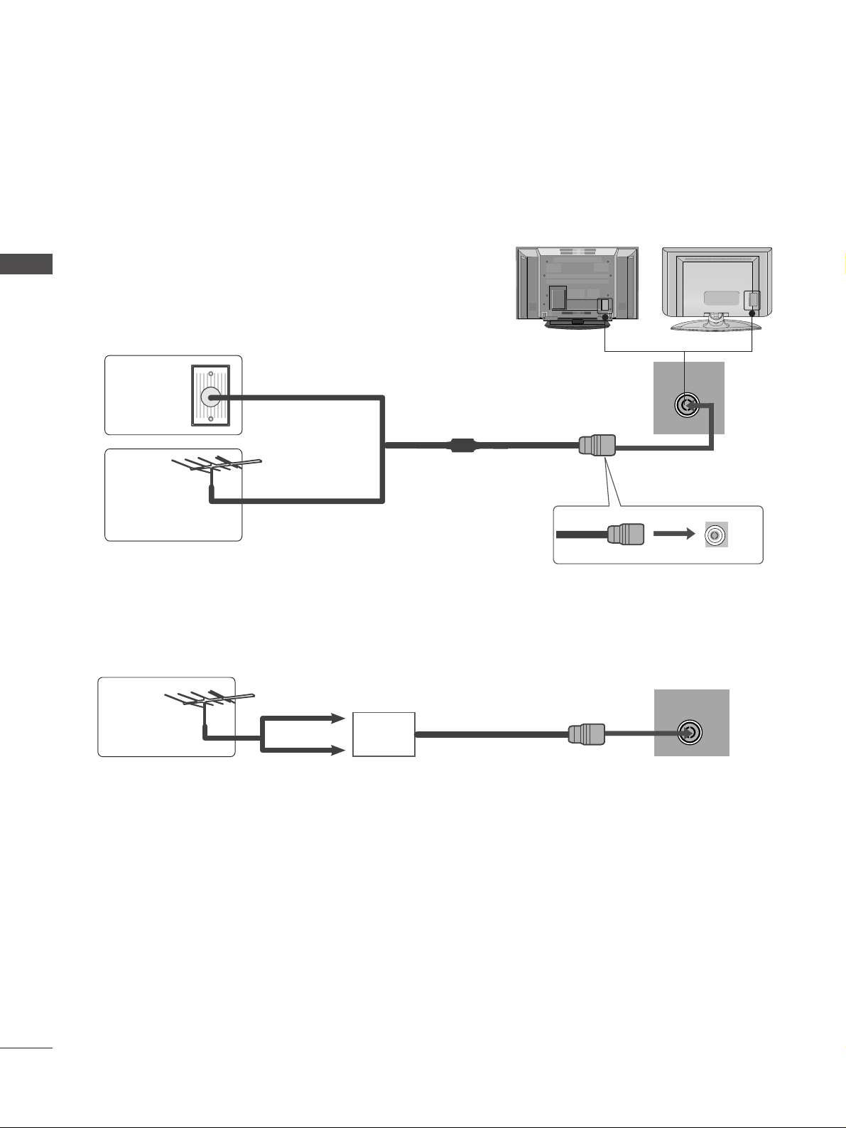
■
For optimum picture quality, adjust antenna direction.
■
An antenna cable and converter are not supplied.
■
To prevent damage do not connect to the mains outlet until all connections are made between the devices.
Multi-family Dwellings/Apartments
(Connect to wall antenna socket)
Single-family Dwellings /Houses
(Connect to wall jack for outdoor antenna)
Outdoor
Antenna
(VHF, UHF)
Wall
Antenna
Socket
RF Coaxial Wire (75 ohm)
ANTENNA CONNECTION
Antenna
UHF
Signal
Amplifier
VHF
■
In poor signal areas, to achieve better picture quality it may be necessary to install a signal amplifier to the
antenna as shown above.
■
If signal needs to be split for two TVs,use an antenna signal splitter for connection.
-Take care not to bend the bronze
wire when connecting to an antenna
port.
- 5V antenna power works In Digital
mode only. (Refer to p. 40)
AV IN 3
L/MONO
R
AUDIO
VIDEO
S-VIDEO
AV IN 3
L/MONO
R
AUDIO
VIDEO
S-VIDEO
USB
AV IN 2
L/MONO
R
AUDIO
VIDEO
S-VIDEO
15
EXTERNAL EQUIPMENT SETUP
HD RECEIVER SETUP
■
This TV can receive Digital RF/Cable signals without an external digital set-top box. However, if you do receive
Digital signals from a digital set-top box or other digital external device, refer to the diagram as shown below.
COMPONENT IN
AUDIOAUDIO
VIDEOVIDEO
AV 1 AV 2
RS-232C IN
VIDEO
EJECT
PCMCIA
CARD SLOT
RS-232C IN
ANTENNA
IN
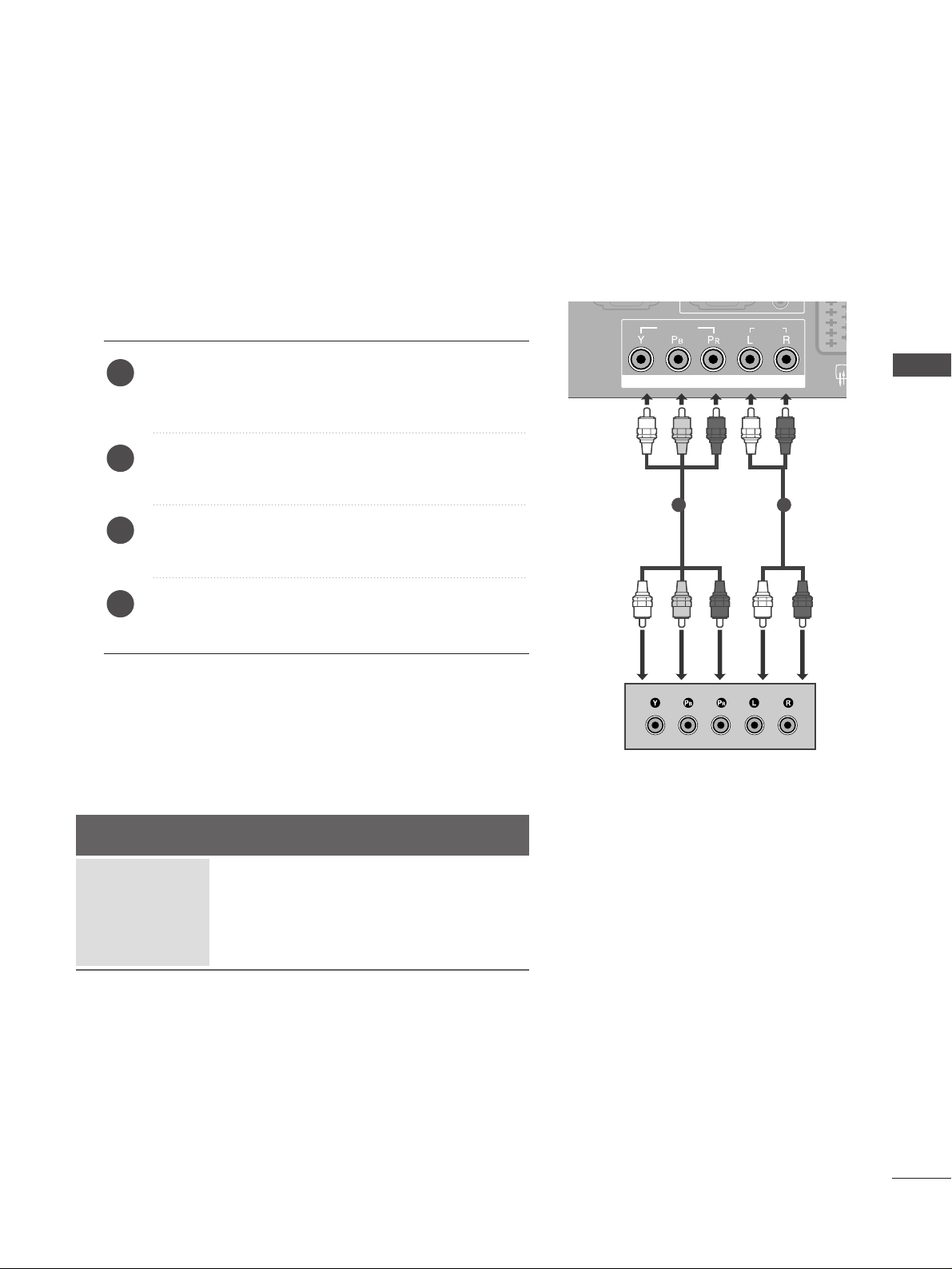
Connecting with a component cable
Connect the video outputs (Y, PB, P
R
)
of the digital set
top box to the
CC OO MM PPOONN EENNTT II NN VVIIDDEEOO
jacks on the
TV.
Connect the audio output of the digital set-top box to
the
CC OO MM PPOONN EENNTT II NN AAUUDD IIOO
jacks on the TV.
Turn on the digital set-top box.
(
Refer to the owner’s manual for the digital set-top box.
)
Select
COMPONENT input source using the
IINN PPUUTT
button on the remote control.
2
3
4
1
Signal
480i/576i
480p/576p
720p/1080i
10 8 0 p
Component
Yes
Yes
Yes
No
HDMI1/2
No
Yes
Yes
Yes
1 2
■
To avoid damaging any equipment, never plug in any power cords until you have finished connecting all equipment.
■
This section on EXTERNAL EQUIPMENT SETUP mainly uses diagrams for the Plasma TV models.
EXTERNAL EQUIPMENT SETUP
16
EXTERNAL EQUIPMENT SETUP
EXTERNAL EQUIPMENT SETUP
AUDIO
VIDEO
AV 1 AV 2
RS-232C IN
AUDIO
VIDEO
AV 1 AV 2
EJECT
PCMCIA
CARD SLOT
RS-232C IN
ANTENNA
IN
RGB(PC)
AUDIO
(RGB/DVI)
RGB IN
COMPONENT IN
AUDIOAUDIO
VIDEOVIDEO
AV 1V 1 AV 2
RS-232C IN
(CONTROL & SERVICE)
(OPTICAL)
DIGITAL AUDIO OUT
HDMI/DVI IN
12
HDMI IN
AUDIO
VIDEO
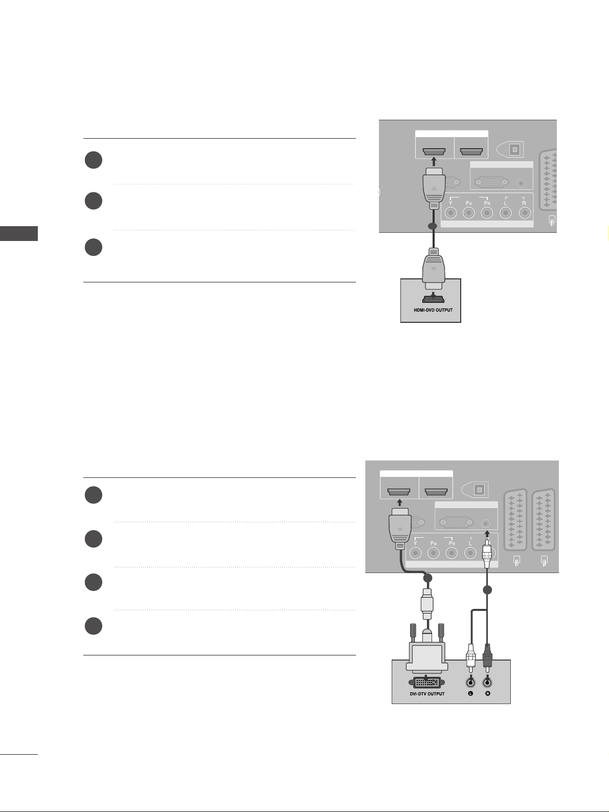
1
2
Connect the digital set-top box to
HHDD MMII//DD VVII IINN
jack
on the TV.
Connect the audio output of the digital set-top box to
the
AAUUDDIIOO IINN (( RRGGBB // DDVVII))
jack on the TV.
Turn on the digital set-top box. (Refer to the owner’s
manual for the digital set-top box.
)
Select
HDMI1 input source using the
IINN PPUUTT
button
on the remote control.
2
3
4
1
Connecting a set-top box with an HDMI cable
Connect the digital set-top box to
HHDD MMII//DD VVII IINN
or
HHDD MMII IINN
jack on the TV.
Turn on the digital set-top box.
(
Refer to the owner’s manual for the digital set-top box.
)
Select
HDMI1 or HDMI2 input source using the
IINN PPUUTT
button on the remote control.
2
3
1
1
Connecting with a HDMI to DVI cable
HDMI/DVI IN
(CONTROL & SERVICE)
HDMI IN
12
RS-232C IN
VIDEO
COMPONENT IN
DIGITAL AUDIO OUT
RGB IN
RGB(PC)
(OPTICAL)
AUDIO
(RGB/DVI)
AUDIO
AV 1 AV 2
17
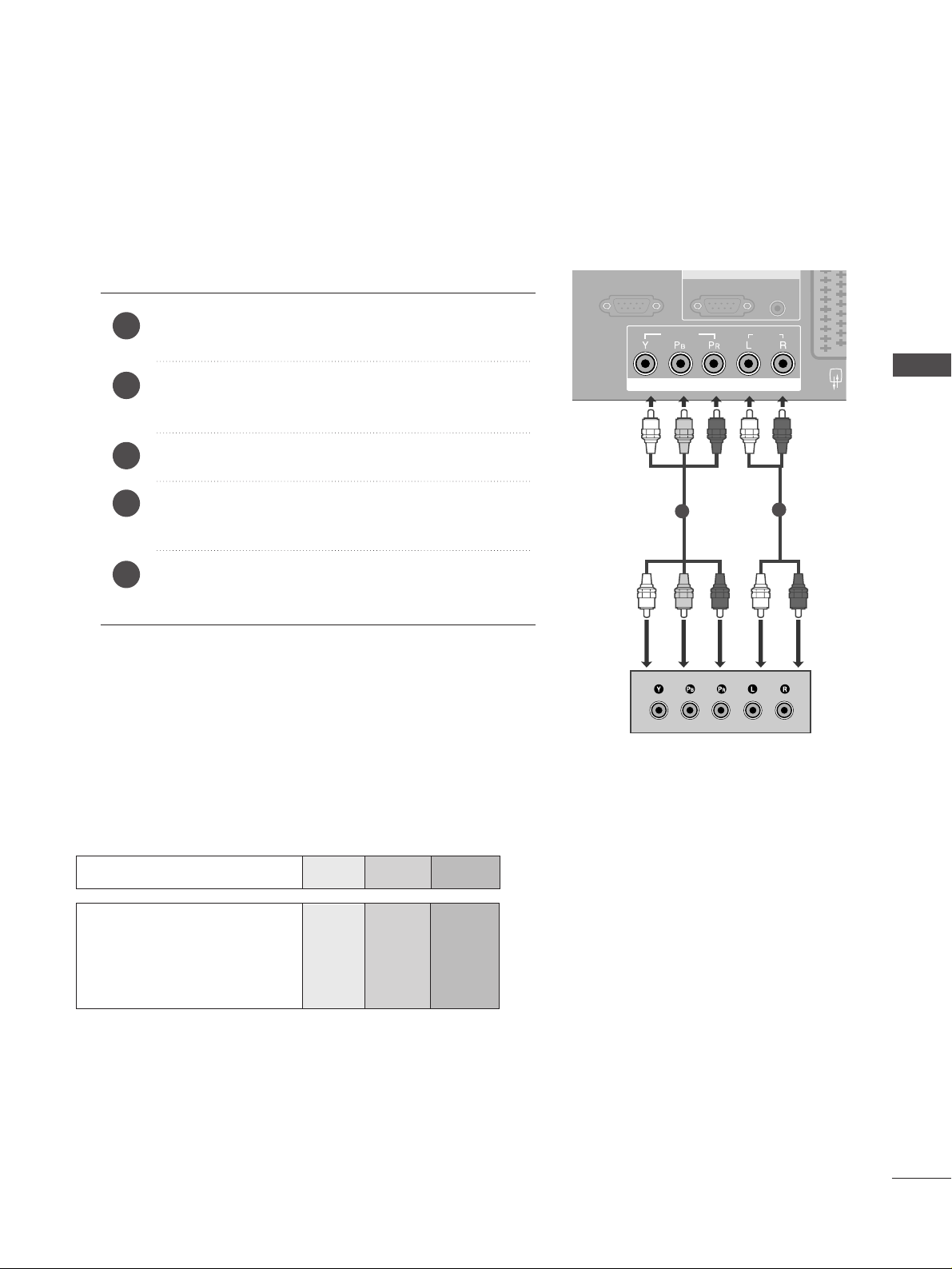
DVD SETUP
Connecting with a component cable
RGB(PC)
AUDIO
(RGB/DVI)
RGB IN
COMPONENT IN
AUDIOAUDIO
VIDEOVIDEO
AV 1 AV 2
RS-232C INRS-232C IN
(CONTROL & SERVICE)
AV IN 3
L/MONO
R
AUDIO
VIDEO
S-VIDEO
Component Input ports
To achieve better picture quality, connect a DVD player to the component input ports as shown below.
Component ports on the TV
YPB PR
Video output ports
on DVD player
Y
Y
Y
Y
PB
B-Y
Cb
Pb
P
R
R-Y
Cr
Pr
Connect the video outputs (Y, P
B, PR
)
of the DVD to the
CC OO MM PPOONN EENNTT II NN VVIIDDEEOO
jacks on the TV.
Connect the audio outputs of the DVD to the
CC OO MM PPOONN EENNTT II NN AAUUDD IIOO
jacks on the TV.
Tu r n on the DVD player, insert a DVD.
Select
COMPONENT input source using the
IINN PPUUTT
button on the remote control.
Refer to the DVD player's manual for operating
instructions.
2
3
4
5
1
1
2
EXTERNAL EQUIPMENT SETUP
18
EXTERNAL EQUIPMENT SETUP
EXTERNAL EQUIPMENT SETUP
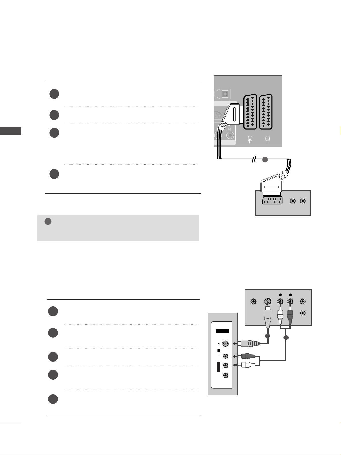
Connecting with a Euro Scart cable
Connect the Euro scart socket of the DVD to the
AAVV 11
Euro scart socket on the TV.
Tu r n on the DVD player, insert a DVD.
Select
AV 1 input source using the
IINN PPUUTT
button on
the remote control.
If connected to
AV 2 Euro scart socket, select AV2
input source.
Refer to the DVD player's manual for operating
instructions.
2
3
4
1
AUDIO
(RGB/DVI)
GB IN
AV 1 AV 2
(OPTICAL)
AUDIO
(R) AUDIO (L)
AUDIO/
VIDEO
AV IN 3
L/MONO
R
AUDIO
VIDEO
S-VIDEO
AV 1 AV 2
EJECT
PCMCIA
CARD SLOT
RS-232C IN
ANTENNA
IN
AUDIO
VIDEO
1
NOTE
!
GG
Any Euro scart cable used must be signal protected.
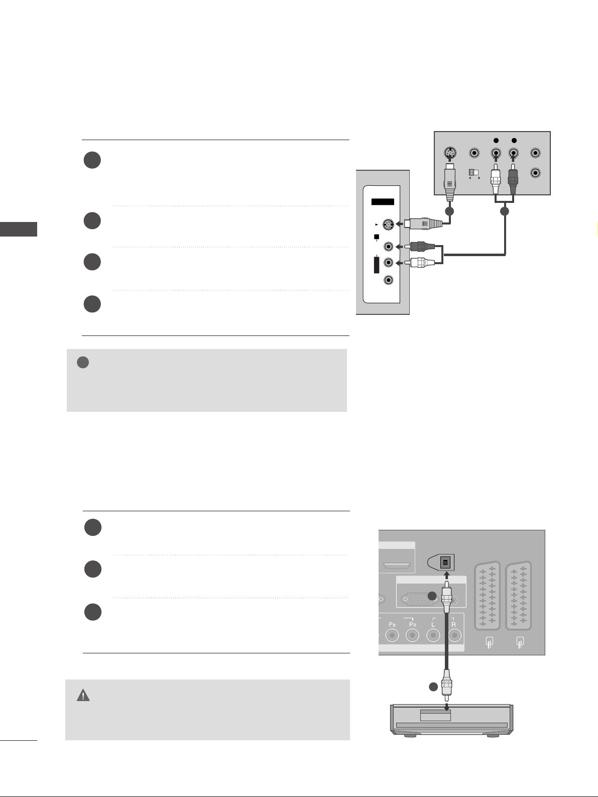
Connecting with a S-Video cable
L R
S-VIDEOVIDEO
OUTPUT
SWITCH
ANT IN
ANT OUT
AV IN 3V IN 3
L/MONOMONO
R
AUDIOAUDIO
VIDEOVIDEO
S-VIDEOS-VIDEO
Connect the S-VIDEO output of the DVD to the
SS--
VVII DD EE OO
input on the TV.
Connect the audio outputs of the DVD to the
AAUU DDIIOO
input jacks on the TV.
Tu r n on the DVD player, insert a DVD.
Select
AV 3 input source using the
IINN PPUUTT
button on
the remote control.
Refer to the DVD player's manual for operating instructions.
2
3
4
5
1
1
2
19
AV IN 3
L/MONO
R
AUDIO
VIDEO
S-VIDEO
RGB(PC)
AUDIO
(RGB/DVI)
RGB IN
AV 1 AV 2
RS-232C IN
(CONTROL & SERVICE)
(OPTICAL)
DIGITAL AUDIO OUT
HDMI/DVI IN
12
HDMI IN
COMPONENT IN
AUDIO
VIDEO
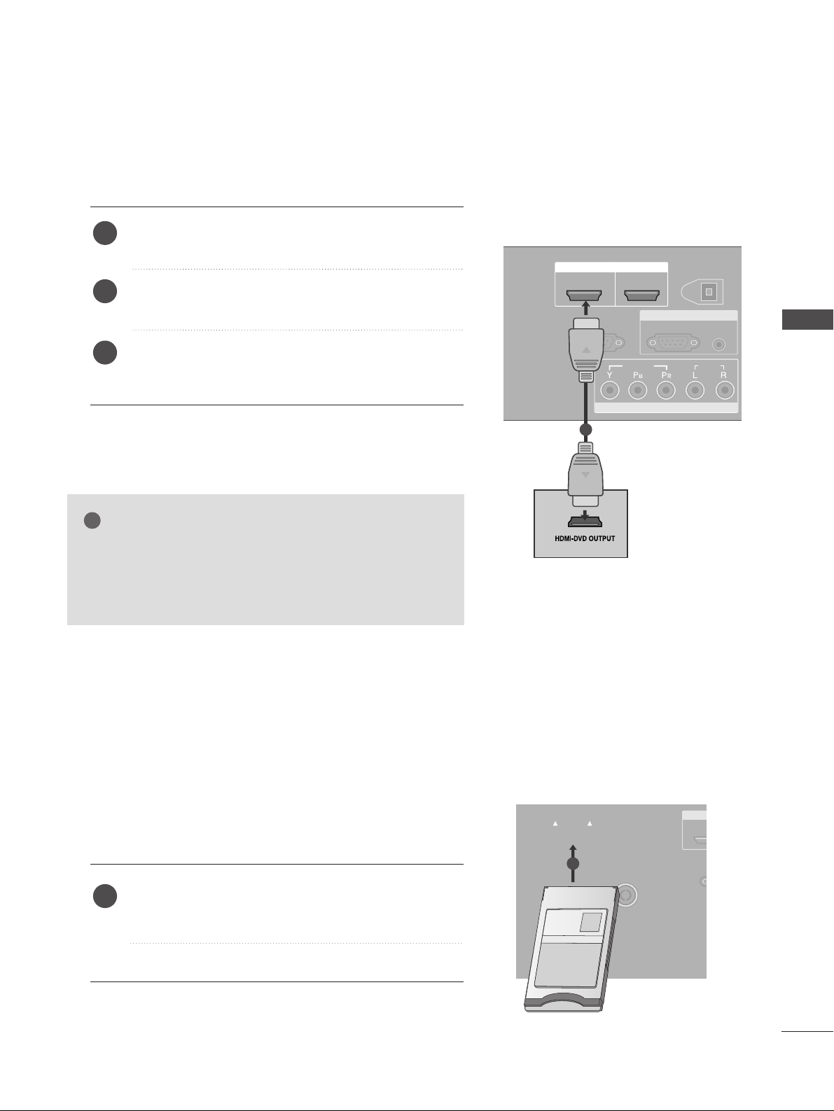
Connecting the HDMI cable
Connect the HDMI output of the DVD to the
HHDDMMII//DDVVII
IINN
or
HHDDMMII IINN
jack on the TV.
Select
HDMI1or HDMI2 input source using the
IINN PPUUTT
button on the remote control.
Refer to the DVD player's manual for operating
instructions.
1
2
3
Insert the CI Module to
PPCC MMCC IIAA
(Personal Computer
Memory Card International Association)
CC AA RR DD SSLLOOTT
of TV as shown.
For further information, see p.43.
1
GG
The TV can receive video and audio signals simultaneously
when using a HDMI cable.
GG
If the DVD player does not support Auto HDMI, you must
TV the output resolution appropriately.
NOTE
!
1
INSERTION OF CI MODULE
AV 1 AV 2
EJECT
PCMCIA
CARD SLOT
RS-232C IN
(CONT
HDMI/
ANTENNAANTENNA
IN
AUDIO
VIDEO
TVTVTV
-- TToo vviiee ww tthhee ssccrr aammbblleedd ((pp aa yy)) ss eerrvviicceess iinn ddiiggiittaall TTVV
mmoo ddee..
-- TThhiiss ffeeaattuu rree iiss nnoott aavvaaiillaabbllee iinn aall ll cc oo uunnttrriiee ss..
1
EXTERNAL EQUIPMENT SETUP
20
EXTERNAL EQUIPMENT SETUP
EXTERNAL EQUIPMENT SETUP
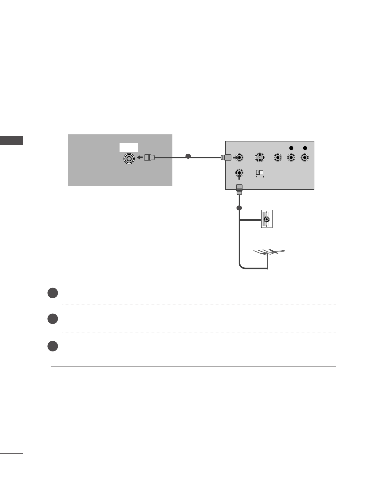
Connecting with a RF cable
■
To avoid picture noise (interference), allow adequate distance between the VCR and TV.
■
If 4:3 picture format is used for an extended period the fixed images on the sides of the screen may remain
visible. (Only Plasma TV models)
VIDEOVIDEO
EJECT
PCMCIA
CARD SLOT
RS-232C INRS-232C IN
(CONTROL & SERVICE)
AUDIOAUDIO
OUTPUT
SWITCH
ANT IN
R
S-VIDEO VIDEO
ANT OUT
L
ANTENNA
IN
Wall Jack
Antenna
Connect the
AANNTT OOUUTT
socket of the VCR to the
AANNTT EENNNN AA II NN
socket on the TV.
Connect the antenna cable to the
AANNTT IINN
socket of the VCR.
Press the
PPLLAAYY
button on the VCR and match the appropriate programme between the TV and VCR for
viewing.
VCR SETUP
1
2
2
3
1
21
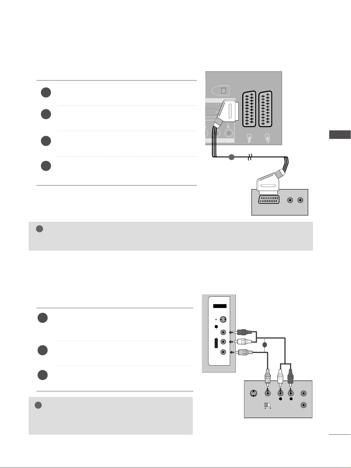
Connecting with a Euro Scart
Connect the Euro scart socket of the VCR to the
AAVV 11
Euro scart socket on the TV.
Insert a video tape into the VCR and press PLAY on
the VCR. (Refer to the VCR owner’s manual.)
Select
AV 1 input source using the
IINN PPUUTT
button on
the remote control.
If connected to
AAVV 22
Euro scart socket, select
AV 2
input source.
2
3
4
1
VIDEO
EJECT
PCMCIA
CARD SLOT
RS-232C IN
AUDIO
AUDIO
(RGB/DVI)
RGB IN
AV 1 AV 2
(OPTICAL)
DIGITAL AUDIO OUT
AUDIO
(R) AUDIO (L)
AUDIO/
VIDEO
AV IN 3
ANTENNA
IN
1
NOTE
!
GG
Any Euro Scart cable used must be signal shielded.
Connecting with an RCA cable
L
R
S-VIDEO
VIDEO
OUTPUT
SWITCH
ANT IN
ANT OUT
AV IN 3
L/MONO
R
AUDIO
VIDEO
S-VIDEO
AV IN 3V IN 3
L/MONOMONO
R
AUDIOAUDIO
VIDEOVIDEO
S-VIDEOS-VIDEO
Connect the
AAUU DD IIOO/VVIIDDEE OO
jacks between TV and
VCR. Match the jack colours (Video = yellow, Audio Left
= white, and Audio Right = red)
Insert a video tape into the VCR and press PLAY on
the VCR. (Refer to the VCR owner’s manual.
)
Select
AV 3 input source using the
IINN PPUU TT
button on
the remote control.
1
2
3
GG
If you have a mono VCR, connect the audio cable from the
VCR to the
AAUU DDIIOO LL // MMOONN OO
jack of the TV.
NOTE
!
1
EXTERNAL EQUIPMENT SETUP
22
EXTERNAL EQUIPMENT SETUP
EXTERNAL EQUIPMENT SETUP
GG
If both S-VIDEO and VIDEO sockets have been connected to
the S-VHS VCR simultaneously, only the S-VIDEO can be
received.
NOTE
!
L
R
S-VIDEO
VIDEO
OUTPUT
SWITCH
ANT IN
ANT OUT
AV IN 3V IN 3
L/L/MONOMONO
R
AUDIOAUDIO
VIDEOVIDEO
S-VIDEOS-VIDEO
Connecting with a S-Video cable
Connect the S-VIDEO output of the VCR to the
SS--
VVIIDDEE OO
input on the TV. The picture quality is
improved; compared to normal composite (RCA cable)
input.
Connect the audio outputs of the VCR to the
AAUU DDIIOO
input jacks on the TV.
Insert a video tape into the VCR and press PLAY on the
VCR. (Refer to the VCR owner’s manual.)
Select
AV 3 input source using the
IINNPPUUTT
button on the
remote control.
2
3
4
1
1 2
DIGITAL AUDIO OUT SETUP
Sending the TV’s audio signal to external audio equipment via the Digital Audio Output (Optical)port.
G
Do not look into the optical output port. Looking at the
laser beam may damage your vision.
CAUTION
RGB(PC)
AUDIO
(RGB/DVI)
RGB IN
AV 1 AV 2
2
HDMI IN
(OPTICAL)
DIGITAL AUDIO OUT
COMPONENT IN
AUDIO
VIDEO
Connect one end of an optical cable to the TV Digital
Audio (Optical)Output port.
Connect the other end of the optical cable to the digital audio (optical)input on the audio equipment.
Set the “TV Speaker option - Off” in the AUDIO menu.
(
G
pp..8888
). Refer to the external audio equipment
instruction manual for operation.
2
3
1
1
2
23
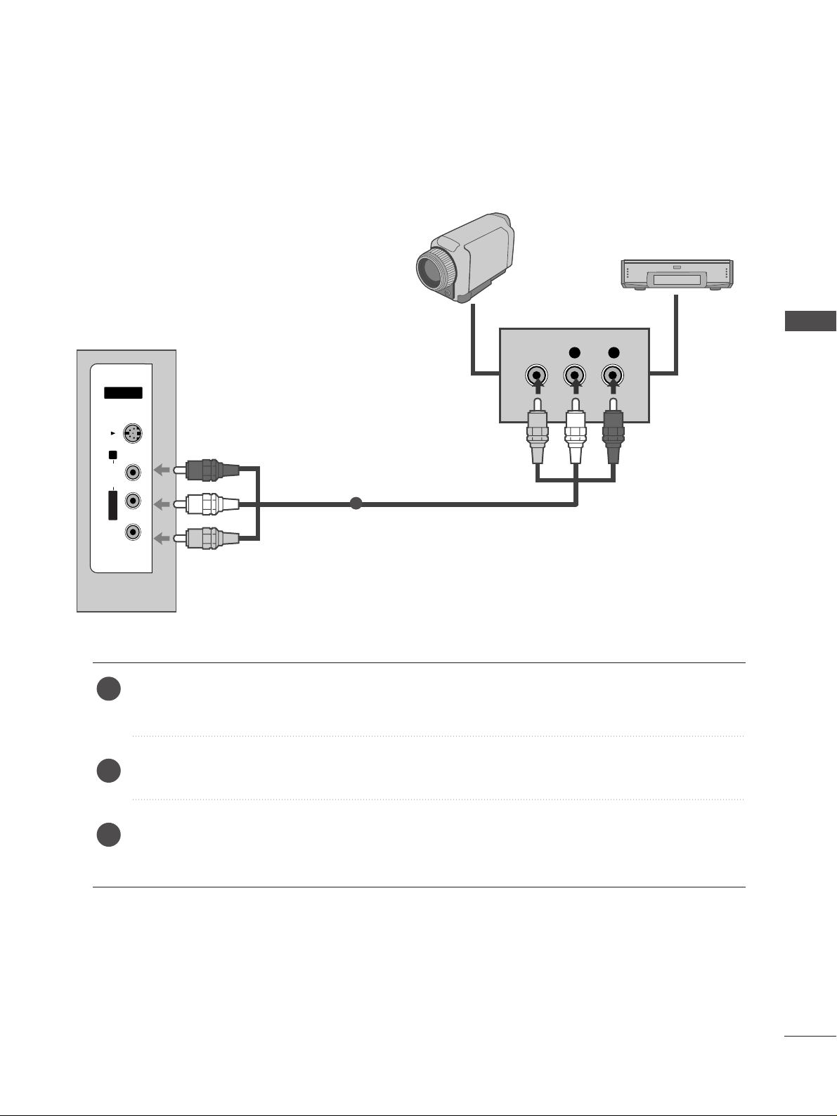
OTHER A/V SOURCE SETUP
Connect the
AAUU DDIIOO/VVII DD EE OO
jacks between TV and external equipment. Match the jack colours
.
(
Video = yellow, Audio Left = white, and Audio Right = red
)
Select AV 3 input source using the
IINN PPUUTT
button on the remote control.
Operate the corresponding external equipment.
Refer to external equipment operating guide.
L R
VIDEO
AV IN 3
L/L/MONOMONO
R
AUDIO
VIDEO
S-VIDEOS-VIDEO
Camcorder
Video Game Set
1
1
2
3
EXTERNAL EQUIPMENT SETUP
24
EXTERNAL EQUIPMENT SETUP
EXTERNAL EQUIPMENT SETUP
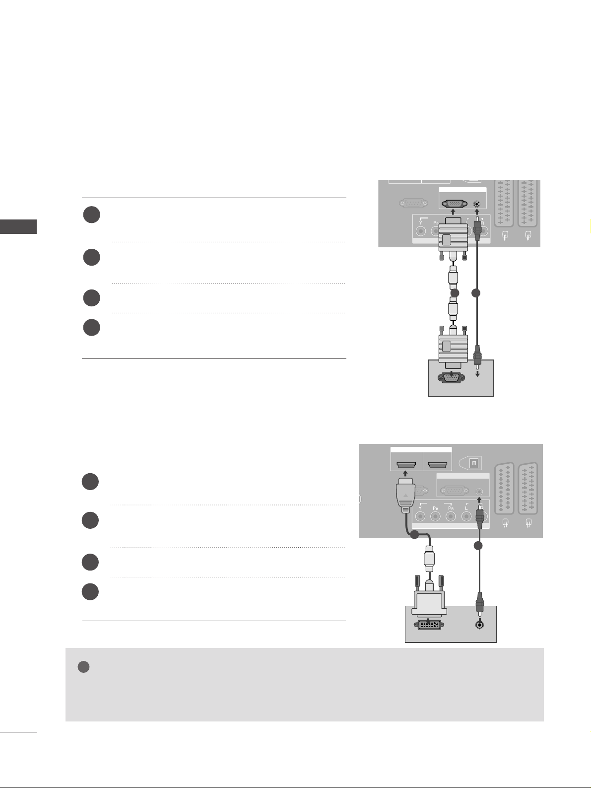
PC SETUP
This TV provides Plug and Play capability, meaning that the PC adjusts automatically to the TV's settings.
Connecting with a D-sub 15 pin cable
AV 1 AV 2
RS-232C INRS-232C IN
(CONTROL & SERVICE)
COMPONENT IN
AUDIOAUDIO
VIDEOVIDEO
RGB(PC)
AUDIO
(RGB/DVI)
RGB IN
RGB OUTPUT
AUDIO
Connect the RGB output of the PC to the
RRGGBB
((
PPCC
))
jack on the TV.
Connect the PC audio output to the
AAUU DDII OO IINN
((RRGGBB // DDVVII))
jack on the TV.
Turn on the PC and the TV.
Select
RGB input source using the
IINN PPUUTT
button on
the remote control.
2
3
4
1
1 2
Connecting with a HDMI to DVI cable
GG
If the PC has a DVI output and no HDMI output, a separated audio connection is necessary.
GG
If the PC does not support Auto DVI, you need to set the output resolution appropriately.
NOTE
!
AV 1 AV 2
EJECT
RS-232C IN
ANTENNA
IN
AUDIO
VIDEO
RGB(PC)
AUDIO
(RGB/DVI)
RGB IN
COMPONENT IN
AUDIOAUDIO
VIDEOVIDEO
AV 1V 1 AV 2V 2
RS-232C INRS-232C IN
(CONTROL & SERVICE)
(OPTICAL)
DIGITAL AUDIO OUT
HDMI/DVI IN
12
HDMI IN
DVI-PC OUTPUT
AUDIO
1
2
Connect the DVI output of the PC to the
HHDD MMII // DDVVII
IINN
jack on the TV.
Connect the PC audio output to the
AAUU DDII OO IINN
((RRGGBB // DDVVII))
jack on the TV.
Turn on the PC and the TV.
Select
HDMI1 input source using the
IINN PPUUTT
button
on the remote control.
2
3
4
1

25
NOTE
!
G
To enjoy vivid picture and sound, connect the PC
to the TV.
G
Avoid keeping a fixed image on the TV ’s screen for
prolonged periods of time.The fixed image may
become permanently imprinted on the screen;use a
screen saver when possible.
G
Connect the PC to the RGB (PC) or HDMI IN (or
HDMI/DVI IN) port of the TV; change the resolution output of PC accordingly.
G
There may be interference relating to resolution,
vertical pattern, contrast or brightness in PC mode.
Change the PC mode to another resolution or change
the refresh rate to another rate or adjust the brightness and contrast on the menu until the picture is
clear. If the refresh rate of the PC graphic card can not
be changed, change the PC graphic card or consult
the manufacturer of the PC graphic card.
G
RGB input only supports the separate horizontal
and vertical synchronization pulses in separate
channels.
G
We recommend using 1360x768, 60Hz (LCD TV
models / 50 inch PLASMA TV models) /
10 2 4x768, 60Hz (42 inch PLASMA TV models)
for the PC mode, these should provide the best
picture quality.
G
Connect the signal cable from the monitor output
port of the PC to the RGB (PC/DTV) port of the
TV or the signal cable from the HDMI output port
of the PC to the HDMI IN (or HDMI/DVI IN) port
on the TV.
G
Connect the audio cable from the PC to the Audio
input on the TV. (Audio cables are not included
with the TV).
G
If using a sound card, adjust PC sound as required.
G
This TV uses a VESA Plug and Play Solution. The
TV provides EDID data to the PC system with a
DDC protocol. The PC adjusts automatically when
using this TV.
G
DDC protocol is preset for RGB (Analogue RGB),
HDMI (Digital RGB) mode.
G
If required, adjust the settings for Plug and Play
functionality.
G
If the graphic card on the PC does not output analogue and digital RGB simultaneously, connect only
one of either RGB or HDMI IN (or HDMI/DVI IN)
to display the PC output on the TV.
G
If the graphic card on the PC does output analogue
and digital RGB simultaneously, switch the TV to
either RGB or HDMI; (the other mode is set to Plug
and Play automatically by the TV.)
G
DOS mode may not work depending on the video
card if you use a HDMI to DVI cable.
G
If you use too long an RGB-PC cable, there may be
interference on the screen. We recommend using
under 5m of cable. This provides the best picture
quality.
EXTERNAL EQUIPMENT SETUP
26
EXTERNAL EQUIPMENT SETUP
EXTERNAL EQUIPMENT SETUP
13 6 6x768
70.08
59.94
75.00
60.31
75.00
74.55
60.00
70.00
75.029
59.87
59.8
59.6
59.988
31.468
31.469
37.684
37.879
46.875
49.725
48.363
56.476
60.123
47.78
47.72
47.56
66.647
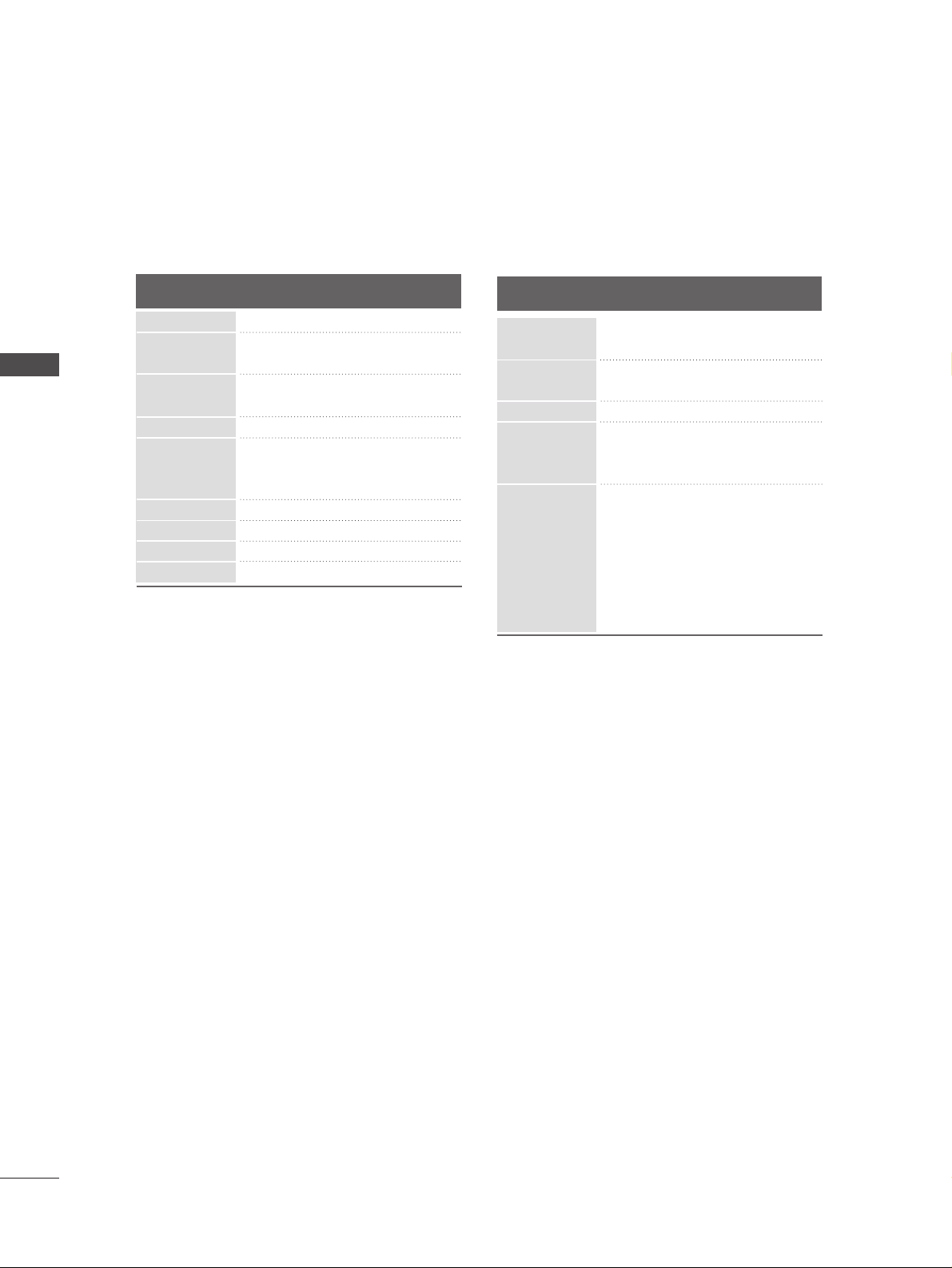
Supported Display Resolution
Resolution
720x400
640x480
Horizontal
Frequency(KHz)
Ver tical
Frequency(Hz)
800x600
832x624
10 2 4x768
12 8 0x768
13 6 0x768
RGB[PC] / HDMI[PC] mode
1920x1080
640x480
720x480
720x576
12 8 0x720
1920x1080
59.94
60.00
59.94
60.00
50.00
50.00
59.94
60.00
59.94
60.00
50.00
24.00
50.00
59.94
60.00
31.469
31.469
31.47
31.50
31.25
37.50
44.96
45.00
33.72
33.75
28.125
27.00
56.25
67.433
67.500
HDMI[DTV] mode
Resolution
Horizontal
Frequency(KHz)
Ver tical
Frequency(Hz)
27
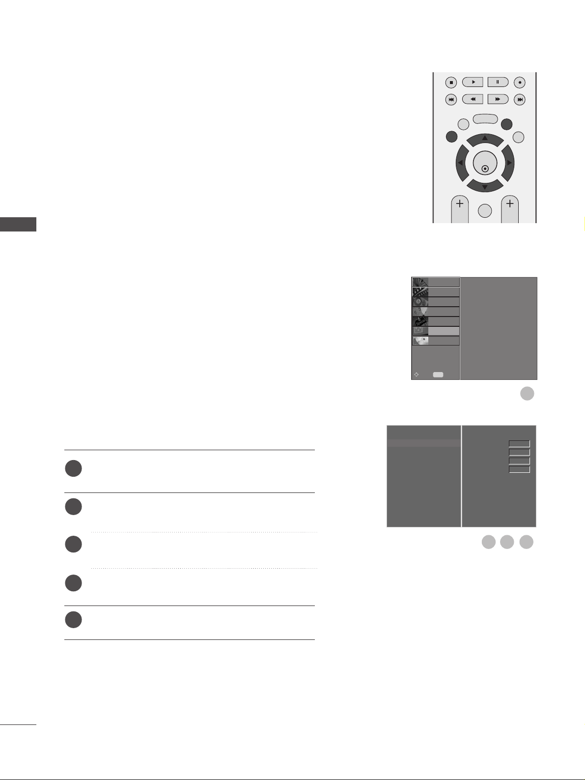
Screen Setup for PC mode
Automatically adjusts picture position and minimizes image
instability.
After adjustment, if the image is still not correct, your TV is
functioning properly but needs further adjustment.
AAuutt oo cc oo nnffiigguurr ee
This function is for automatic adjustment of the screen position, clock, and phase. The displayed image will be unstable
for a few seconds while the auto configuration is in progress.
Press the
MMEENNUU
button and then use
D
or
E
button
to select the SCREEN menu.
Press the
G
button and then use
D
or
E
button to
select Auto Config..
Press the
G
button to start Auto Config..
• When Auto Config. has finished, OK will be shown
on screen.
• If the position of the image is still not correct, try
Auto adjustment again.
• If picture needs to be adjusted again after Auto
adjustment in RGB (PC), you can adjust the
Manual Config..
Press the EXIT button to return to normal TV viewing.
Auto Configure (RGB [PC] mode only)
Auto Config. G
Manual Config.
XGA Mode
Aspect Ratio
Reset
To Set
OK
EXIT
TIME
SHIFT
TIME
SHIFT
VOL PR
GUIDE
BACK MENU
DVR
MARK
FAV
1
3
2
1
2
3
4
Auto Config.
Manual Config.
XGA Mode
Aspect Ratio
Reset
SETUP
O
PICTURE
O
Prev.
MENU
Move
AUDIO
O
TIME
O
OPTION
O
SCREEN
G
D V R
O
EXTERNAL EQUIPMENT SETUP
28
EXTERNAL EQUIPMENT SETUP
EXTERNAL EQUIPMENT SETUP
If the picture is not clear after auto adjustment and especially if characters are still trembling, adjust the picture
phase manually.
To correct the screen size, adjust
CC ll oo cckk
.
This function works in the following mode : RGB[PC].
CC ll oo cckk
This function is to minimize any vertical bars or stripes
visible on the screen background the horizontal
screen size will also change.
PPhh aa ssee
This function allows you to remove any horizontal
noise and clear or sharpen the image of characters.
Press the MENU button and then use
D
or
E
button
to select the SCREEN menu.
Press the Gbutton and then
D
or
E
button to select
Manual Config..
Press the
G
button and then
D
or
E
button to select
Phase, Clock, H-Position or V-Position.
Press the
F
or
G
button to make appropriate adjust-
ments.
Press the EXIT button to return to normal TV viewing.
Adjustment for screen Phase, Clock, Position
Auto Config.
Manual Config.
G
XGA Mode
Aspect Ratio
Reset
Phase
Clock
H-Position
V-Position
0
0
0
0
OK
EXIT
TIME
SHIFT
TIME
SHIFT
VOL PR
GUIDE
BACK MENU
DVR
MARK
FAV
1
1
2
3
4
5
3 4
2
Auto Config.
Manual Config.
XGA Mode
Aspect Ratio
Reset
SETUP
O
PICTURE
O
Prev.
MENU
Move
AUDIO
O
TIME
O
OPTION
O
SCREEN
G
D V R
O
 Loading...