

LG 42PT81, 50PT80, 42PT80, 50PT81 User Manual

Please read this manual carefully before operating
your set.
Retain it for future reference.
Record model number and serial number of the set.
See the label attached on the back cover and quote
this information to your dealer when you require
service.
PLASMA TV
OWNER’S MANUAL
PLASMA TV MODELS
4422 PPTT88
**
5500 PPTT88
**
ENGLISH

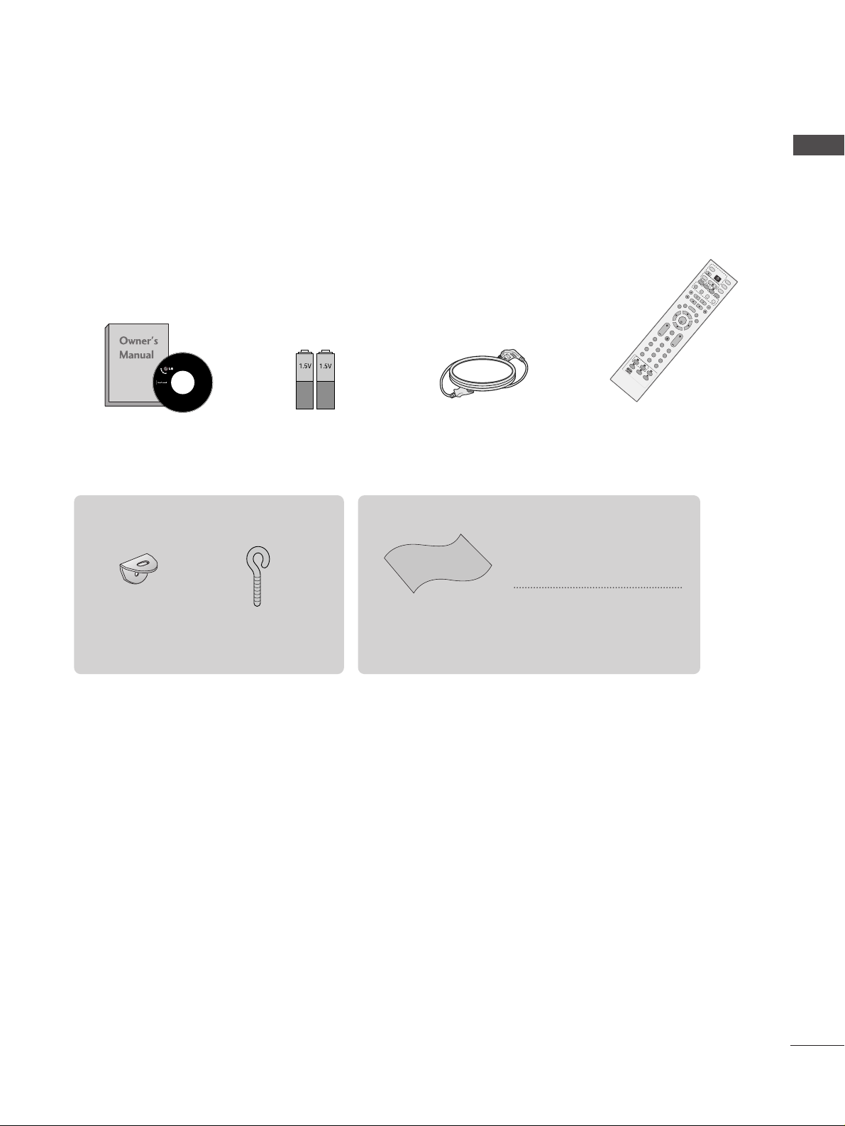
ACCESSORIES
1
ACCESSORIES
Ensure that the following accessories are included with your TV. If an accessory is missing, please contact the
dealer where you purchased the product.
Owner’s Manual Batteries
Remote Control
Power Cord
Polishing Cloth
Polish the screen with the cloth
*Slightly wipe stained spot on the
exterior only with the cleansing
cloths for the product exterior if
there is stain or fingerprint on surface
of the exterior.
Do not wipe roughly when removing
stain. Please be cautious of that
excessive power may cause scratch
or discoloration.
OK
INPU
T
M
O
DE
TVTV
DV
D
RAT
IO
M
E
N
U
VO
L
P
O
S
ITIO
N
INDEX
PR
P
I
P
E
XIT
TIM
E
SH
IF
T
TIM
E
SH
IF
T
LIST
LIV
E
T
V
I/II
DVR
SIZE
VC
R
PIP
PR-
PIP PR+
P
I
P
I
N
P
U
T
P
OW
E
R
B
RIGH
T
123
456
789
0
F
A
V
/
M
A
R
K
R
E
V
E
A
L
?
TEXT
SIMPLIN
K
INPU
T
M
U
TE
TIM
E
H
O
L
D
S
W
A
P
OK
RAT
M
E
N
U
VO
L
P
O
S
IT
IO
N
INDEX
PR
E
X
IT
TIME
SH
IFT
TIME
S
H
IFT
LIS
T
LIV
E
T
V
SIZE
PIP PR- PIP PR
123
456
789
0
F
A
V
/
M
A
R
K
R
E
V
E
?
SIMP
LINK
M
U
TE
TIME
HO
LD
SLEEP
Q.VIEW
SLEEP
Q.VIEW
DVR
2-Wall brackets
2-eye-bolts
This feature is not available for all models.
2
CONTENTS
CONTENTS
WATCHING TV /PROGRAMME CONTROL
Remote Control Key Functions.................................30
Turning on the TV....................................................... 32
Programme Selection ................................................. 32
Volume Adjustment......................................................32
On Screen Menus Selection and Adjustment.......33
Auto Programme Tuning............................................ 34
Manual Programme Tuning ....................................... 35
Fine Tuning .....................................................................36
Assigning a Station Name ..........................................37
Booster............................................................................38
Programme Edit ........................................................... 39
Favourite Programme.................................................. 40
Calling the Programme Table ................................... 41
Input Source Selection................................................42
Key lock.......................................................................... 43
................................................................ 44
WATCHING TV / PROGRAMME CONTROL
AACCCCEESSSSOORRIIEESS
.....................................................1
PREPARATION
Home Menu......................................................................4
Front Panel Controls..................................................... 5
Back Panel Information ................................................ 6
Attaching the TV to a Wall ...........................................7
Back Cover for Wire Arrangement............................ 8
Desktop Pedestal Installation ..................................... 9
Wall Mount: Horizontal installation .......................... 9
Antenna Connection................................................... 10
EXTERNAL EQUIPMENT SETUP
HD Receiver Setup........................................................11
DVD Setup..................................................................... 14
VCR Setup ..................................................................... 17
Other A/V Source Setup .......................................... 20
External Stereo Setup................................................. 21
USB in Setup .................................................................22
PC Setup........................................................................23
- Screen Setup for PC Mode................................26
PREPARATION
DVR (DIGITAL VIDEO RECORDER)
TimeShift Mode(Pause & Replay of Live TV)...... 46
Format hard disk ...........................................................49
Instant Recording.........................................................50
Manual Record ..............................................................52
Schedule List..................................................................53
Record Quality ..............................................................53
To use the USB device................................................54
Recorded TV Programme List....................................56
USB Backup ..................................................................59
Photo List........................................................................62
Music List........................................................................66
Movie List .......................................................................69
Subtitle............................................................................71
DivX Registration Code..............................................72
3
CONTENTS
PICTURE CONTROL
Watching PIP(Picture-in-Picture) .............................73
Picture Size (Aspect Ratio)Control.........................75
Preset Picture Settings
- Picture Mode-Preset............................................77
- Auto Colour Tone Control(Warm/Medium/Cool)
78
Manual Picture Adjustment
- Picture Mode-User option.................................79
- Colour Tone - User option................................80
-
Picture Improvement Technology
...................81
Demo .................................................................82
Advanced - Cinema......................................................83
Advanced - Black(Darkness) Level...........................84
Picture Reset..................................................................85
Image Sticking Minimization(ISM) Method ..........86
Low-Power Picture Mode............................................87
SOUND & LANGUAGE CONTROL
Auto Volume Leveler ....................................................88
Preset Sound Settings - Sound Mode ....................89
Sound Setting Adjustment - User Mode ...............90
Balance ............................................................................91
TV Speakers On/Off Setup .......................................92
I/II
- Stereo/Dual Reception.......................................93
- NICAM Reception................................................94
- Speaker Sound Output Selection....................94
On-Screen Menu Language /Country Selection
...... 95
PICTURE CONTROL
APPENDIX
Troubleshooting..........................................................103
Maintenance ...............................................................105
Product Specifications..............................................106
Programming the Remote Control .......................107
IR Codes ........................................................................110
External Control Device Setup................................112
TIME SETTING
Clock Setup....................................................................96
Auto On/Off Timer Setting........................................97
Sleep Timer Setting......................................................98
Auto Shut-off Setting ..................................................99
TELETEXT
Switch On/Off ...........................................................100
SIMPLE Text .................................................................100
TOP Text .......................................................................101
FASTEXT .......................................................................101
Special Teletext Functions........................................102
Recorded TV
Manual Record
Schedule List
Photo List
Music List
Movie List
TV Menu
HIGH
NORMAL
DVR
DVR
Free Space
4
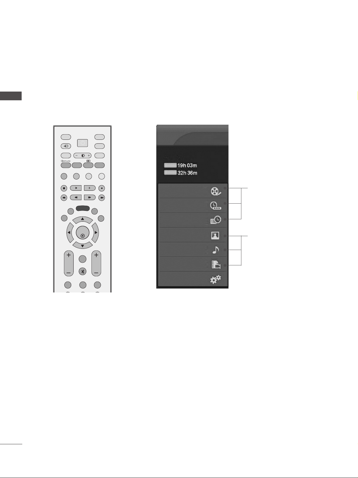
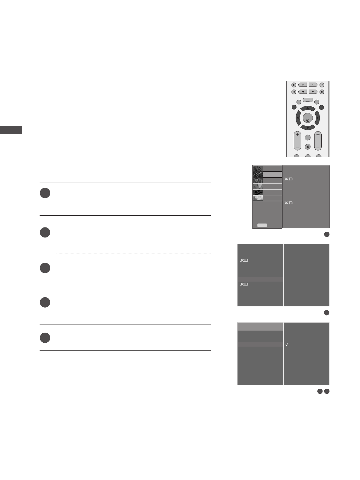
HOME MENU
PREPARATION
PREPARATION
This menu is a contents guide.
In Home Menu, you enter the Recorded list of DVR, Manual Recording of the DVR, Schedule List ,Photo List,
Music List, Movie List or TV Menu.
OK
INPUT MODE
TVTV
DVD
RATIO
MENU
VOL PR
PIP
EXIT
TIME
SHIFT
TIME
SHIFT
LIST
LIVE TV
I/II
DVR
VCR
PIP PR- PIP PR+
PIP INPUT
POWER
123
FAV/
MARK
TEXT
SIMPLINK
INPUT
MUTE
SWAP
BRIGHT
G
pp..4466
G
pp..6622~77 00
Home
Home
5
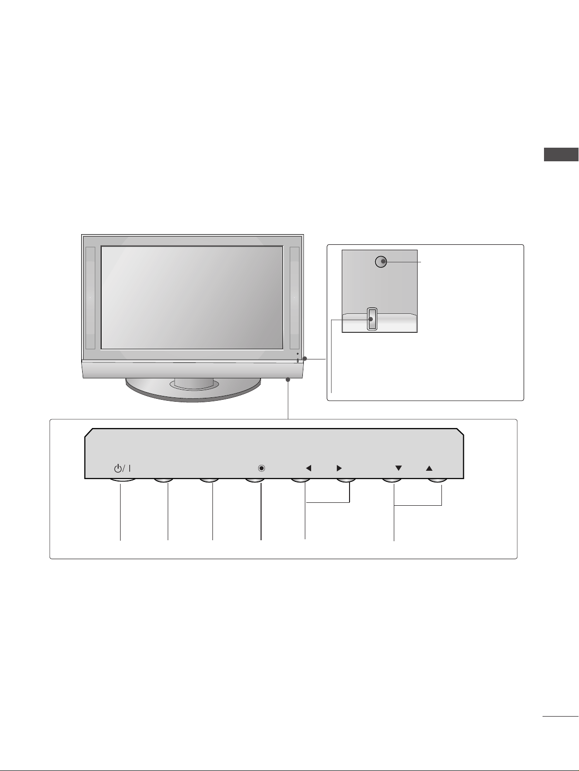
FRONT PANEL CONTROLS
PREPARATION
A
This is a simplified representation of the front panel. Here shown may be somewhat different from your TV.
A
If your product has a protection film attached, remove the film and then wipe the product with a polishing
cloth.
PROGRAMME
Buttons
VOLUME
Buttons
MENU
Button
OK
Button
INPUT
Button
POWER
Button
Remote Control Sensor
Power/Standby Indicator
• illuminates red in standby mode.
• illuminates green when the set is switched on.
• illuminates orange when the set is switched off
during recording.
INPUT
MENU
OK
VOL
PR
6
PREPARATION
PREPARATION
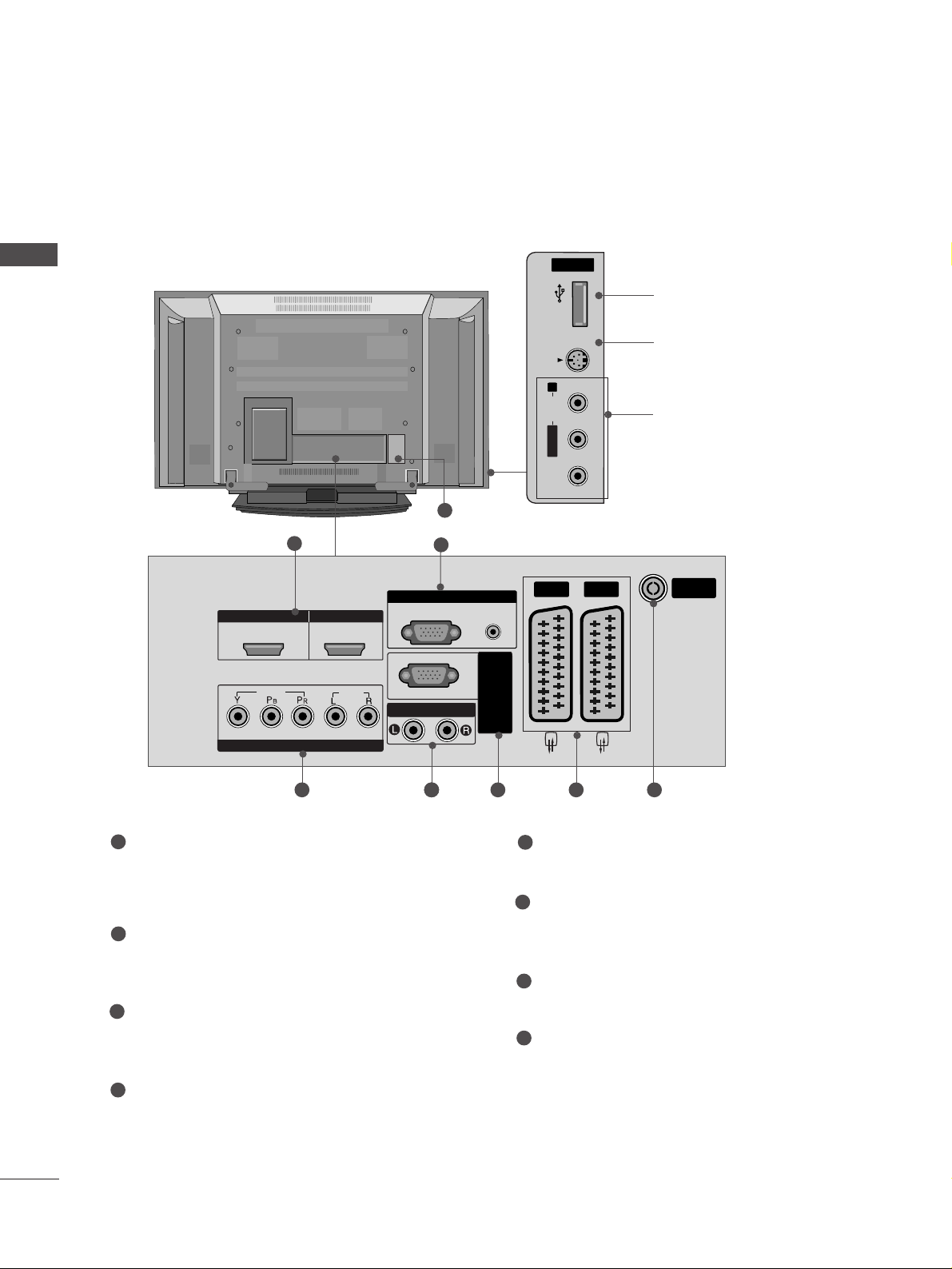
BACK PANEL INFORMATION
A
This is a simplified representation of the back panel. Here shown may be somewhat different from your TV.
USB
AV IN 3
L/ MONO
R
AUDIO
S-VIDEO
USB Input
S-Video Input
Connect S-Video out from an
S-VIDEO device.
Audio/Video Input
Connect audio/video output
from an external device to
these jacks.
USBUSB
AV IN 3V IN 3
L/MONO
R
AUDIOAUDIO
VIDEOVIDEO
S-VIDEOS-VIDEO
HDMI/DVI1, HDMI2 Input
Connect a HDMI signal to HDMI IN.
Or DVI(VIDEO)signal to HDMI/DVI port with DVI
to HDMI cable.
RGB/Audio Input
Connect the monitor output from a PC to the
appropriate input port.
Component Input
Connect a component video/audio device to
these jacks.
Variable Audio Output
Connect an external amplifier or add a subwoofer
to your surround sound system.
RS-232C Input
(CONTROL&SERVICE)Port
Connect to the RS-232C port on a PC.
Euro Scart Socket (AV1/AV2)
Connect scart socket input or output from an
external device to these jacks.
Antenna Input
Connect over-the-air signals to this jack.
Power Cord Socket
This TV operates on an AC power. The voltage is
indicated on the Specifications page. Never
attempt to operate the TV on DC power.
1
2
3
4
5
6
7
8
8
ARIABLE A
UDIO OUT
RS-232C IN
(CONTR
OL&SER
VICE)
USB
AV IN 3
L/ MONO
R
AUDIO
VIDEO
S-VIDEO
1
3 64 6 7
2
5
1 2
VIDEO
COMPONENT IN
HDMI IN HDMI/DVI IN
AUDIO
VARIABLE A
RGB IN
RGB
(PC)
UDIO OUT
AUDIO
(RGB/DVI)
VICE)
OL&SER
RS-232C IN
(CONTR
AV 1 AV 2
ANTENNA
IN
7
PREPARATION
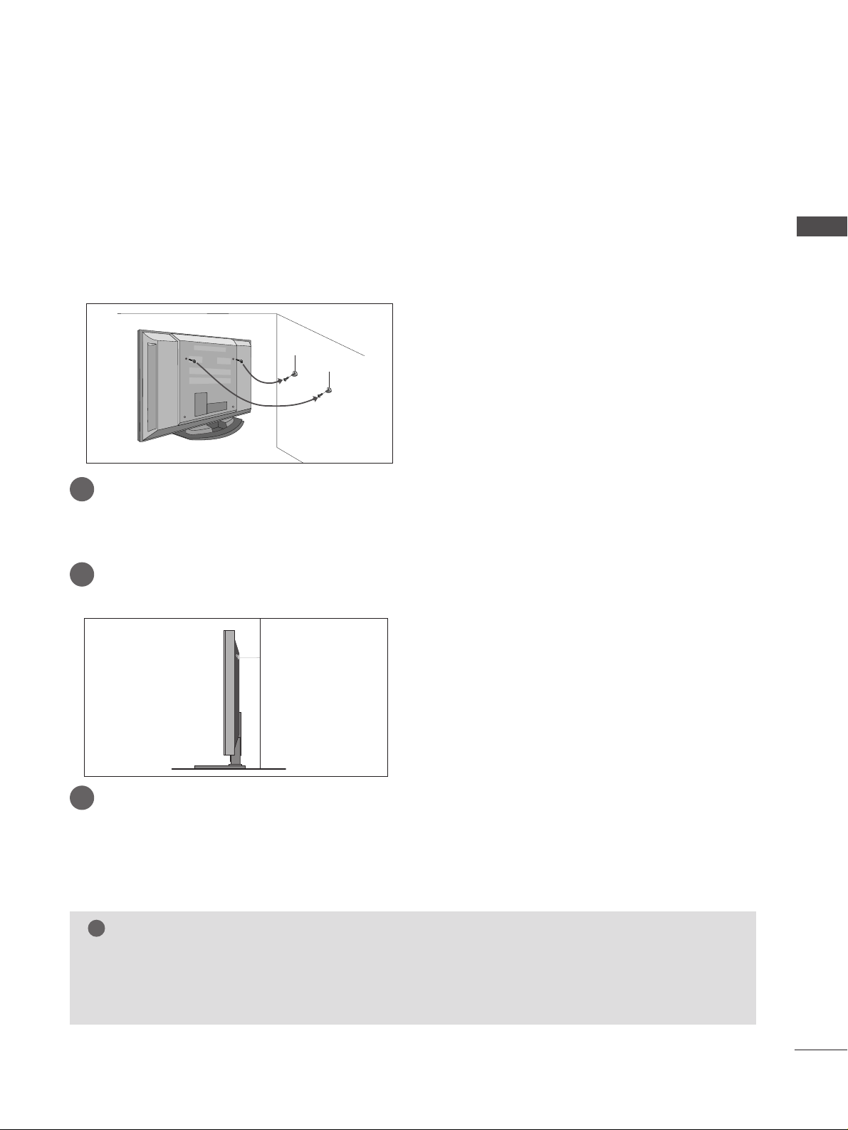
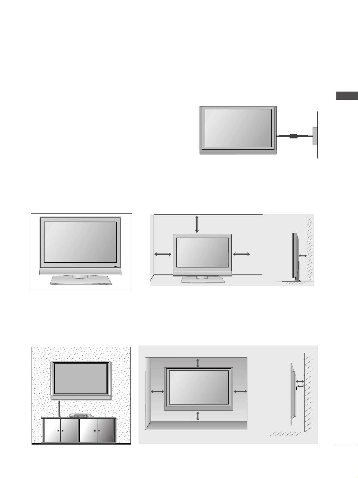
ATTACHING THE TV TO A WALL(This feature is not available for all models.)
A
Set it up close to the wall so the product doesn’t fall over when it is pushed backwards.
A
The instructions shown below is a safer way to set up the product, which is to fix it on the wall so the
product doesn’t fall over when it is pulled in the forward direction. It will prevent the product from
falling for-ward and hurting people. It will also prevent the product from damage caused by fall. Please
make sure that children don’t climb on or hang from the product.
NOTE
!
G
When moving the product to another place undo the ropes first.
G
Use a product holder or a cabinet that is big and strong enough for the size and weight of the product.
G
To use the product safely make sure that the height of the bracket that is mounted on the wall is same
as that of the product.
2
3
1
1
2
Use the eye-bolts or TV brackets/bolts to fix the product to the wall as shown in the picture.
(If your product has the bolts in the eye-bolts position before inserting the eye-bolts, loosen the bolts.)
* Insert the eye-bolts or TV brackets/bolts and tighten them securely in the upper holes.
Secure the wall brackets with the bolts (not provided as parts of the product, must purchase separately) on
the wall. Match the height of the bracket that is mounted on the wall.
3
Use a sturdy rope (not provided as parts of the product, must purchase separately) to tie the
product. It is safer to tie the rope so it becomes horizontal between the wall and the product.
8
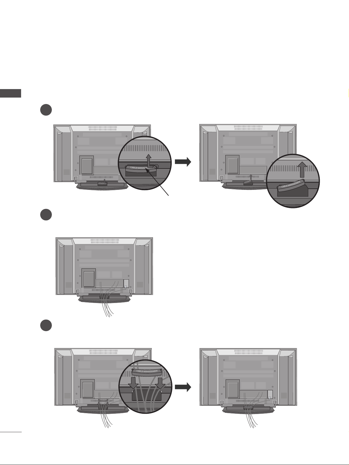
BACK COVER FOR WIRE ARRANGEMENT
PREPARATION
PREPARATION
Connect the cables as necessary.
To connect an additional equipment, see the External equipment Setup section.
Reinstall the
CC AABBLLEE MMAANNAA GGEEMMEENNTT
as shown.
2
1
3
Hold the
CC AABBLLEE MMAANNAA GGEEMMEENNTT
with hands and push it as shown.
CABLE MANAGEMENT
9
PREPARATION
A
The TV can be installed in various ways such as on a wall, or on a desktop etc.
A
The TV is designed to be mounted horizontally.
WALL MOUNT: HORIZONTAL INSTALLATION
For proper ventilation, allow a clearance of 4" on each side and from the wall. Detailed installation instructions are available from your dealer, see the optional Tilt Wall Mounting Bracket Installation and Setup Guide.
4 inches
4 inches
4 inches
4 inches
4 inches
Power Supply
Short-circuit
Breaker
GROUNDING
Ensure that you connect the earth ground wire to prevent
possible electric shock. If grounding methods are not possible, have a qualified electrician install a separate circuit
breaker.
Do not try to ground the unit by connecting it to telephone
wires, lightening rods, or gas pipes.
DESKTOP PEDESTAL INSTALLATION
For proper ventilation, allow a clearance of 4" on each side and from the wall.
4 inches
4 inches
4 inches
4 inches
R
ANTENNA
IN
USB
AV IN 3
L/ MONO
R
AUDIO
VIDEO
S-VIDEO
USB
AV IN 2
L/MONO
R
AUDIO
S-VIDEO
10
PREPARATION
PREPARATION
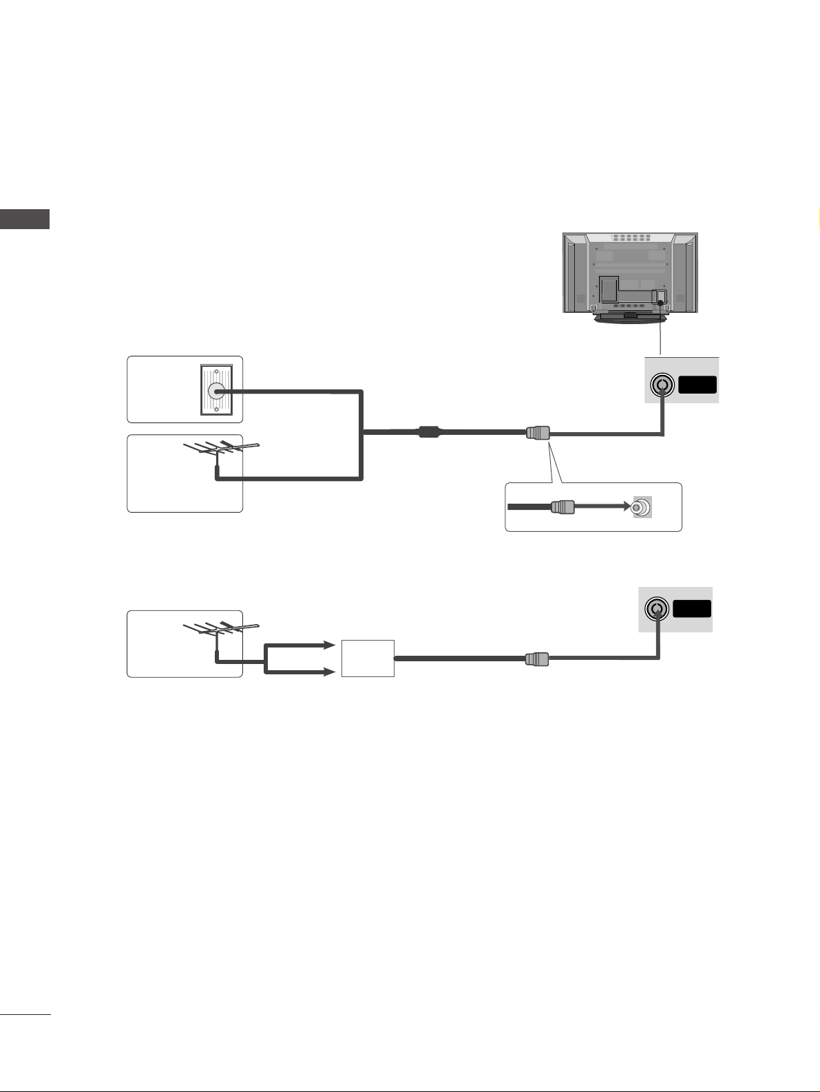
ANTENNA CONNECTION
A
To prevent the equipment damage, never plug in any power cords until you have finished connecting all equipment.
USB
AV IN 3
L/ MONO
R
AUDIO
VIDEO
S-VIDEO
A
For optimum picture quality, adjust antenna direction.
A
An antenna cable and converter are not supplied.
Multi-family Dwellings/Apartments
(Connect to wall antenna socket)
Single-family Dwellings /Houses
(Connect to wall jack for outdoor antenna)
Outdoor
Antenna
Wall
Antenna
Socket
RF Coaxial Wire (75 ohm)
Antenna
UHF
Signal
Amplifier
VHF
A
In poor signal areas,to get better picture quality, install a signal amplifier to the antenna as shown to the right.
A
If signal needs to be split for two TVs,use an antenna signal splitter for connection.
ANTENNA
IN
11
HD RECEIVER SETUP
EXTERNAL EQUIPMENT SETUP
EXTERNAL EQUIPMENT SETUP
VAR
COMPONENT INCOMPONENT IN
AUDIO
VIDEO
1 2
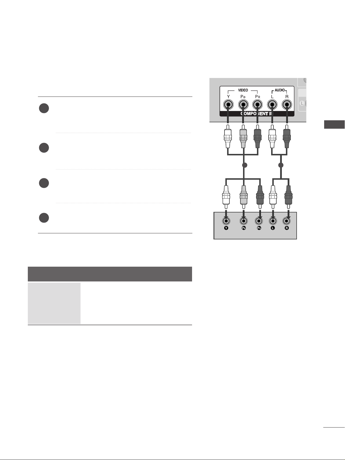
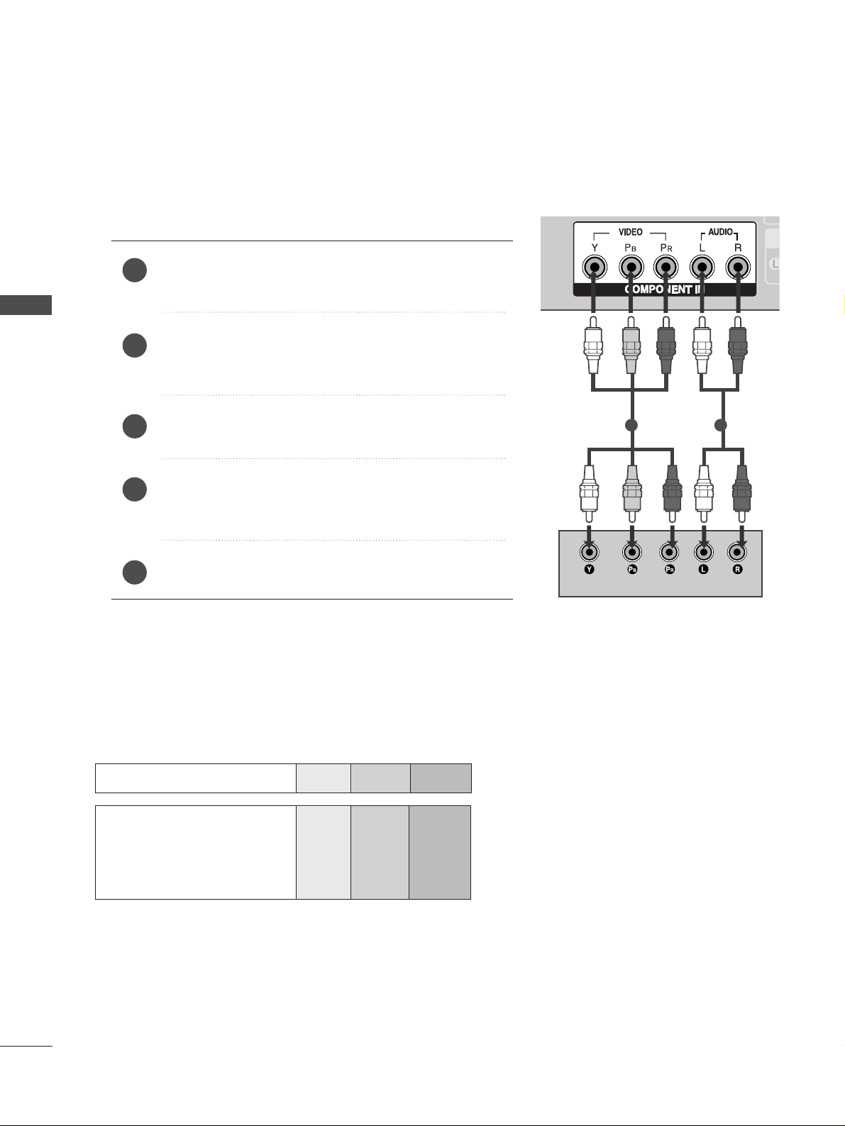
When connecting with a component cable
Connect the video outputs (Y, PB
, PR
)
of the digital set
top box to the
CC OOMMPPOO NNEENNTT IINN VVII DDEEOO
jacks on the
set.
Connect the audio output of the digital set-top box to
the
CC OOMMPPOO NNEENNTT IINN AAUUDDIIOO
jacks on the set.
Turn on the digital set-top box.
(
Refer to the owner’s manual for the digital set-top box.
)
Select
Component input source with using the
IINNPPUUTT
button on the remote control.
2
3
4
1
Signal
480i/576i
480p/576p
720p/1080i
1080p(50/60Hz)
Component
Yes
Yes
Yes
Yes
HDMI1/DVI, HDMI2
No
Yes
Yes
Yes
A
To prevent the equipment damage, never plug in any power cords until you have finished connecting all equipment.
A
Here shown may be somewhat different from your TV.
12
EXTERNAL EQUIPMENT SETUP
EXTERNAL EQUIPMENT SETUP
HDMI/DVI IN
HDMI/DVI IN
HDMI IN HDMI IN HDMI/DVI IN HDMI/DVI IN
12
VA
COMPONENT INCOMPONENT IN
AUDIO
VIDEO
HDMI IN HDMI/DVI IN
1 2
HDMI-DTV OUTPUT
1
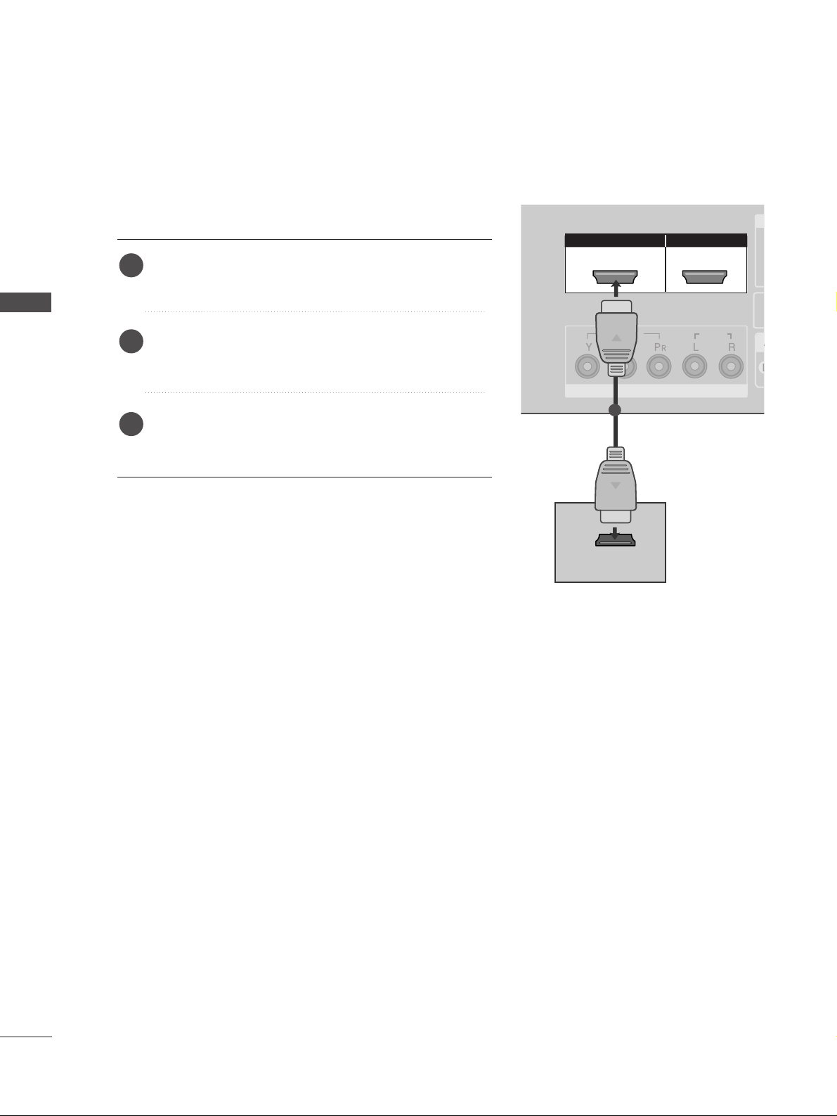
When connecting with a HDMI cable
Connect the HDMI output of the digital set-top box to
the
HHDDMMII//DD VVII IINN 11
or
HHDDMMII IINN 22
jack on the set.
Select
HDMI1/DVI or HDMI2 input source with using
the
IINNPPUUTT
button on the remote control.
Turn on the digital set-top box.
(
Refer to the owner’s manual for the digital set-top box.
)
2
3
1
13
EXTERNAL EQUIPMENT SETUP
HDMI IN HDMI IN HDMI/DVI IN HDMI/DVI IN
12
VARIABLE AUDIO OUT
COMPONENT INCOMPONENT IN
AUDIO
VIDEO
AUDIO
(RGB/DVI)
RGB
(PC)
RGB IN
RS-232C IN
(CONTROL&SERVICE)
RS-232C IN
(CONTROL&SERVICE)
HDMI/DVI IN
1
RGB
(PC)
AUDIO
(RGB/DVI)
RGB IN
HDMI/DVI IN
1
1
2
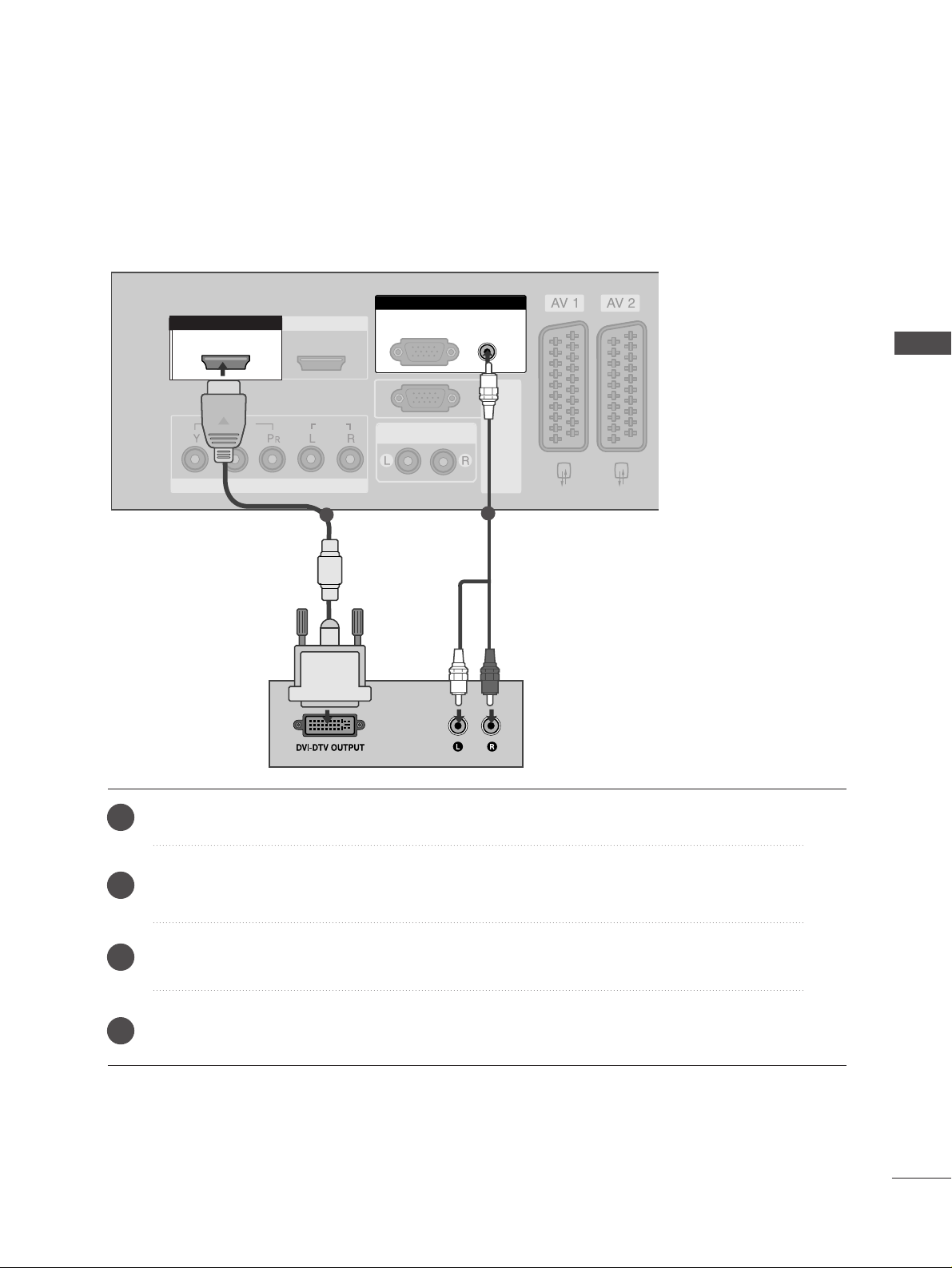
Connect the DVI output of the digital set-top box to the
HHDDMMII//DD VVII IINN 11
jack on the set.
Connect the audio output of the digital set-top box to the
AAUU DDIIOO((RRGGBB //DD VVII))
jack on the set.
Turn on the digital set-top box. (Refer to the owner’s manual for the digital set-top box.
)
Select
HDMI1/DVI input source with using the
IINNPPUUTT
button on the remote control.
2
3
4
1
When connecting with a HDMI to DVI cable
14
DVD SETUP
EXTERNAL EQUIPMENT SETUP
EXTERNAL EQUIPMENT SETUP
VA
COMPONENT INCOMPONENT IN
AUDIO
VIDEO
1 2
Component Input ports
To get better picture quality, connect a DVD player to the component input ports as shown below.
Component ports on the TV
YPB PR
Video output ports
on DVD player
Y
Y
Y
Y
PB
B-Y
Cb
Pb
P
R
R-Y
Cr
Pr
When connecting with a component cable
Connect the video outputs (Y, P
B, PR
)
of the DVD to the
CC OOMMPPOO NNEENNTT IINN VVII DDEEOO
jacks on the set.
Connect the audio outputs of the DVD to the
CC OOMM PP OO--
NNEENNTT IINN AAUUDDIIOO
jacks on the set.
Turn on the DVD player, insert a DVD.
Select
Component input source with using the
IINNPPUUTT
button on the remote control.
Refer to the DVD player's manual for operating instructions.
2
3
4
5
1
15
EXTERNAL EQUIPMENT SETUP
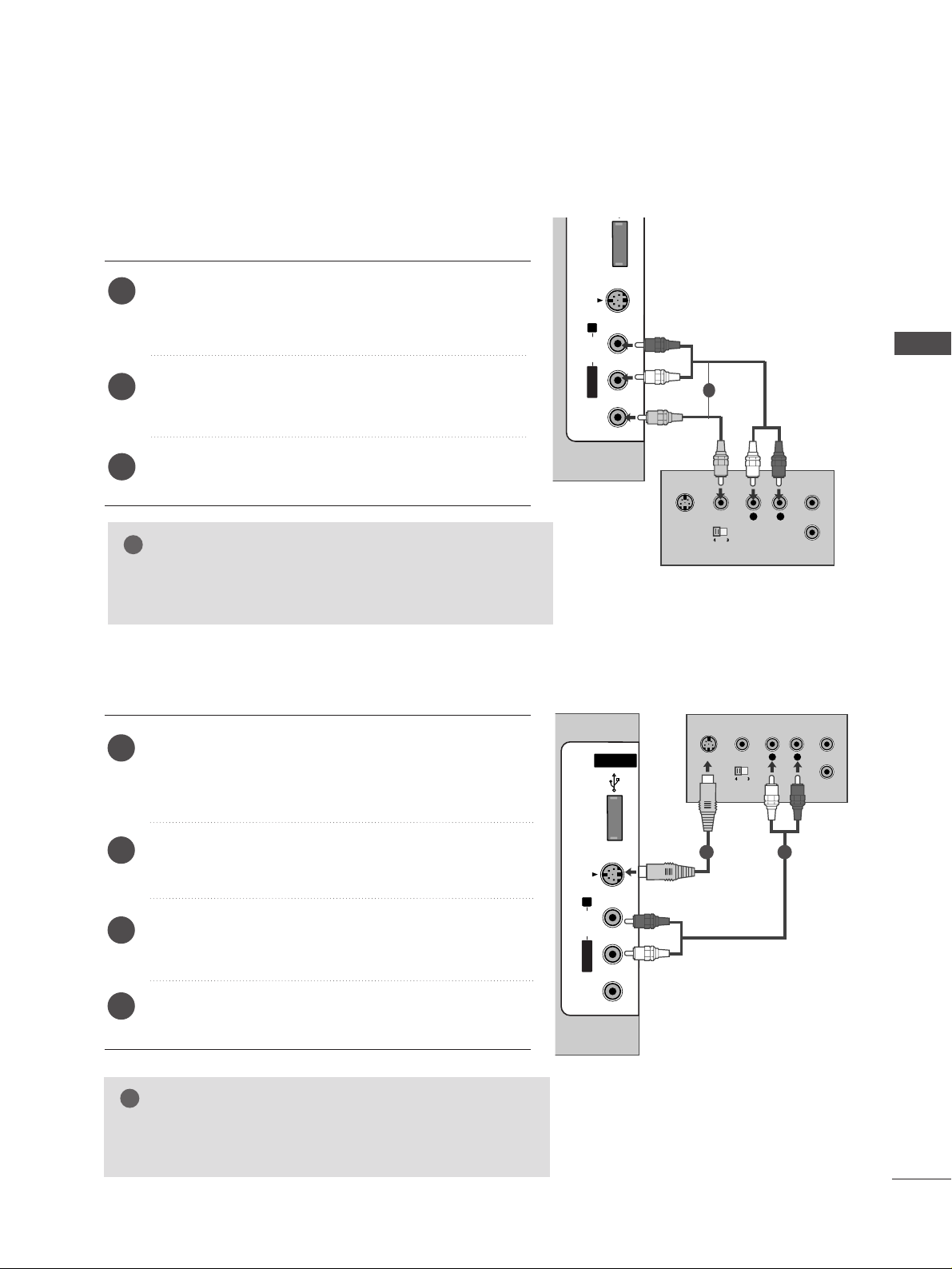
When connecting with an S-Video cable
Connect the S-VIDEO output of the DVD to the
SS--
VVII DDEEOO
input on the set.
Connect the audio outputs of the DVD to the
AAUU DDII OO
input jacks on the set.
Turn on the DVD player, insert a DVD.
Select
AV 3 input source with using the
IINNPPUUTT
but-
ton on the remote control.
Refer to the DVD player's manual for operating
instructions.
2
3
4
5
1
USB INUSB IN
AV IN 3
L/MONO
R
AUDIOAUDIO
VIDEOVIDEO
S-VIDEO
L
R
S-VIDEO
VIDEO
OUTPUT
SWITCH
ANT IN
ANT OUT
AUDIO
(RGB/DVI)
B
RGB IN
RS-232C IN
(CONTROL&SERVICE)
RS-232C IN
(CONTROL&SERVICE)
ANTENNA
IN
ANTENNA
IN
(R) AUDIO (L)
AUDIO/
VIDEO
HDMI IN HDMI/DVI IN
12
USB IN
AV IN 3
L/ MONO
R
AUDIO
VIDEO
S-VIDEO
(R) AUDIO (L)
AUDIO/
VIDEO
1
2
When connecting with a Euro Scart
Connect the Euro scart socket of the DVD to the
AAVV11
Euro
scart socket on the set.
Turn on the DVD player, insert a DVD.
Select
AV 1 input source with using the
IINNPPUUTT
button on
the remote control.
If connected to
AV 2 Euro scart socket, select AV 2 input
source.
Refer to the DVD player's manual for operating instructions.
2
3
4
1
NOTE
!
GG
Please use the shield scart cable.
1

16
EXTERNAL EQUIPMENT SETUP
EXTERNAL EQUIPMENT SETUP
HDMI IN HDMI IN HDMI/DVI IN HDMI/DVI IN
12
COMPONENT INCOMPONENT IN
AUDIO
VIDEO
HDMI IN HDMI/DVI IN
1 2
HDMI-DVD OUTPUT
USB IN
AV IN 3
L/ MONO
R
AUDIO
VIDEO
S-VIDEO
1
When connecting HDMI cable
Connect the HDMI output of the DVD to the
HHDDMMII//DD VVII IINN 11
or
HHDDMMII IINN 22
jack on the set.
Select
HDMI1/DVI or HDMI2 input source with
using the
IINNPPUUTT
button on the remote control.
Refer to the DVD player's manual for operating
instructions.
1
2
3
GG
TV can receive the video and audio signal simultaneously
with using a HDMI cable.
GG
If the DVD does not support Auto HDMI, you need to set
the output resolution appropriately.
NOTE
17
VCR SETUP
EXTERNAL EQUIPMENT SETUP
AUDIO OUT
AUDIO
(RGB/DVI)
RGB IN
RS-232C IN
(CONTROL&SERVICE)
RS-232C IN
(CONTROL&SERVICE)
ANTENNA
IN
ANTENNA
IN
ANTENNA
IN
OUTPUT
SWITCH
ANT IN
R
S-VIDEO VIDEO
ANT OUT
L
USB IN
AV IN 3
L/ MONO
R
AUDIO
VIDEO
S-VIDEO
Wall Jack
Antenna
1
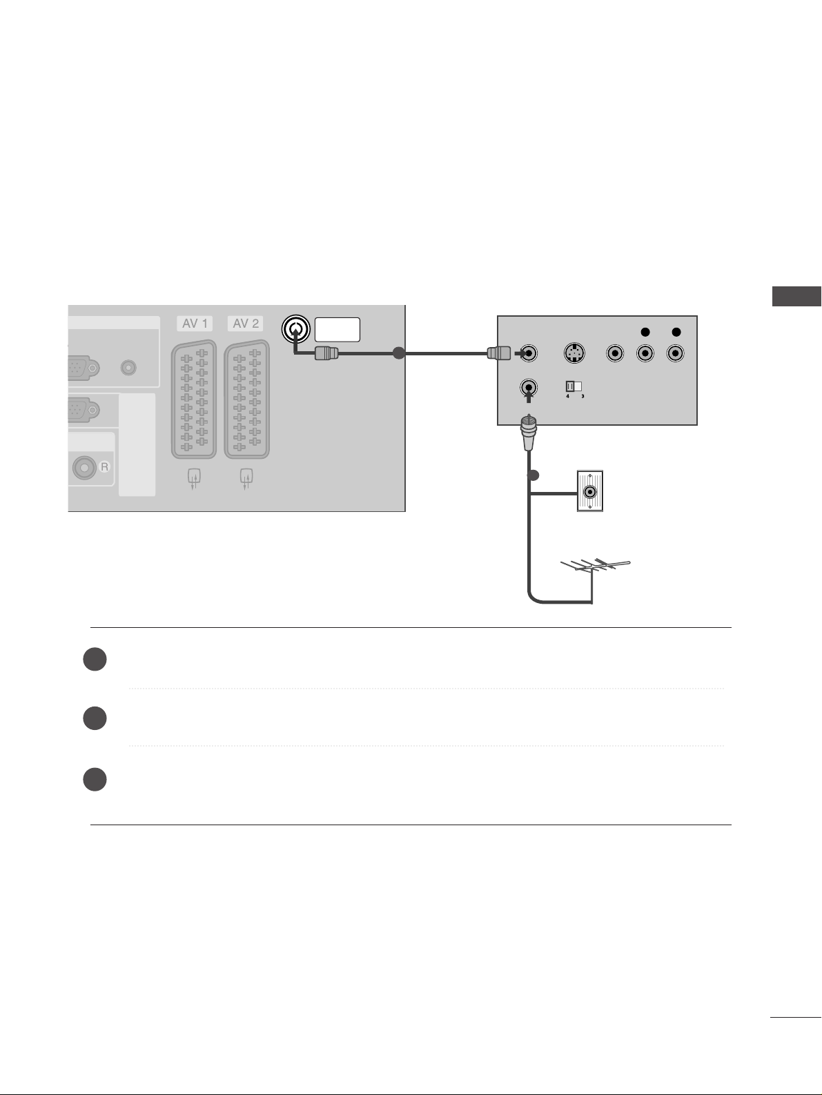
When connecting with an antenna
n
To avoid picture noise (interference), leave an adequate distance between the VCR and TV.
n
Typically a frozen still picture from a VCR. If the 4:3 picture format is used; the fixed images on the sides of
the screen may remain visible on the screen.
Connect the
AANNTT OOUUTT
socket of the VCR to the
AANNTT EENN NNAA IINN
socket on the set.
Connect the antenna cable to the
AANNTT IINN
socket of the VCR.
Press the
PPLLAAYY
button on the VCR and match the appropriate programme between the TV and VCR for
viewing.
1
2
2
3
1

USB IN
AV IN 3
L/ MONO
R
AUDIO
VIDEO
S-VIDEO
AUDIO
(RGB/DVI)
RGB IN
RS-232C IN
(CONTROL&SERVICE)
RS-232C IN
(CONTROL&SERVICE)
ANTENNA
IN
ANTENNA
IN
(R) AUDIO (L)
AUDIO/
VIDEO
(R) AUDIO (L)
AUDIO/
VIDEO
USB IN
AV IN 3
L/ MONO
R
AUDIO
VIDEO
S-VIDEO
18
EXTERNAL EQUIPMENT SETUP
EXTERNAL EQUIPMENT SETUP
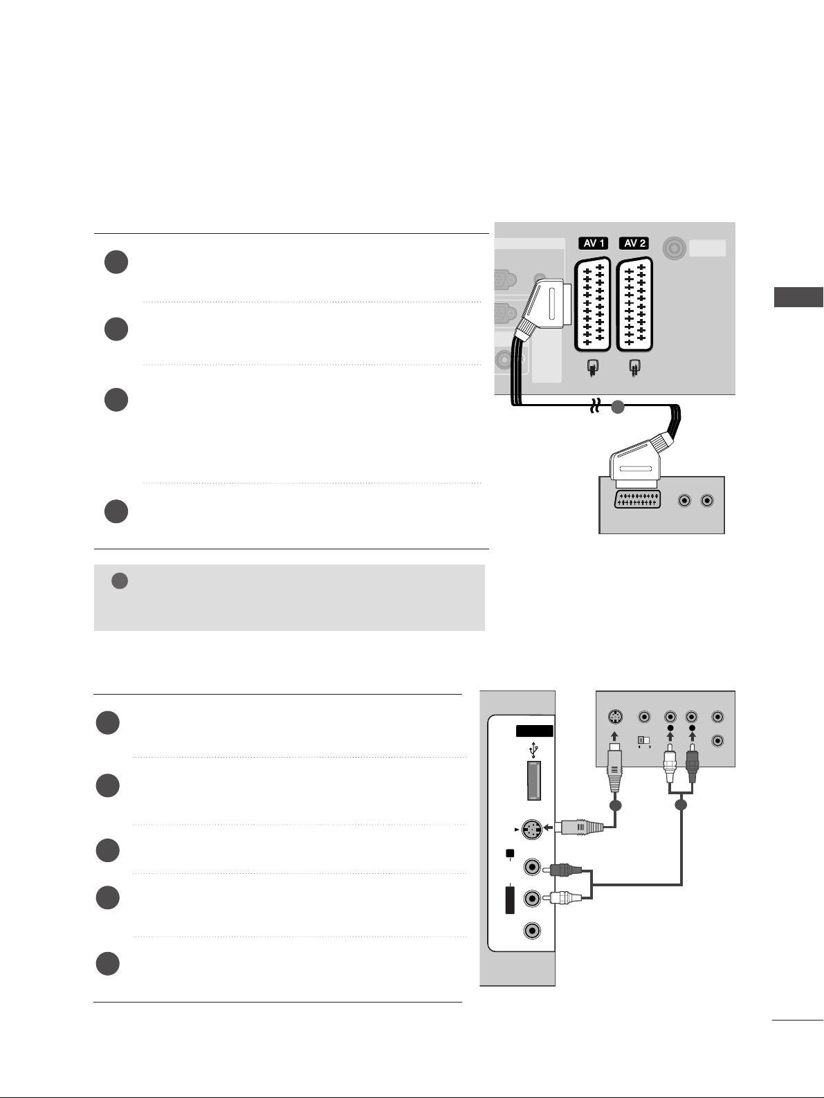
When connecting with a Euro Scart
Connect the Euro scart socket of the VCR to the
AAVV11
Euro
scart socket on the set.
Insert a video tape into the VCR and press PLAY on the
VCR. (Refer to the VCR owner’s manual.)
Select
AV 1 input source with using the
IINNPPUUTT
button
on the remote control.
If connected to
AAVV 22
Euro scart socket, select
AV 2 input
source.
2
3
1
1
NOTE
!
GG
If you want to use the EURO scart cable, you have to use the signal shielded Euro scart cable.
EXTERNAL EQUIPMENT SETUP
19
GG
If both S-VIDEO and VIDEO sockets have been connected to
the S-VHS VCR simultaneously, only the S-VIDEO can be
received.
NOTE
!
USB INUSB IN
AV IN 3
L/MONO
R
AUDIOAUDIO
VIDEOVIDEO
S-VIDEO
L
R
S-VIDEO
VIDEO
OUTPUT
SWITCH
ANT IN
ANT OUT
USB INUSB IN
AV IN 3
L/MONO
R
AUDIOAUDIO
VIDEOVIDEO
S-VIDEO
L
R
S-VIDEO
VIDEO
OUTPUT
SWITCH
ANT IN
ANT OUT
USB IN
AV IN 3
L/ MONO
R
AUDIO
VIDEO
S-VIDEO
When connecting with an S-Video cable
Connect the S-VIDEO output of the VCR to the
SS--
VVII DDEEOO
input on the set. The picture quality is
improved; compared to normal composite (RCA cable)
input.
Connect the audio outputs of the VCR to the
AAUU DDII OO
input jacks on the set.
Insert a video tape into the VCR and press PLAY on
the VCR. (Refer to the VCR owner’s manual.)
Select
AV 3 input source with using the
IINNPPUUTT
but-
ton on the remote control.
2
3
4
1
When connecting with a RCA cable
Connect the
AAUUDDII OO/VVII DDEEOO
jacks between TV and
VCR. Match the jack colours (Video = yellow, Audio Left
= white, and Audio Right = red)
Insert a video tape into the VCR and press PLAY on the
VCR. (Refer to the VCR owner’s manual.
)
Select
AV 3 input source using the
IINN PP UUTT
button on
the remote control.
1
2
3
GG
If you have a mono VCR, connect the audio cable from the
VCR to the
AAUU DDIIOO LL//MMOONNOO
jack of the set.
NOTE
!
1
1 2

20
OTHER A/V SOURCE SETUP
EXTERNAL EQUIPMENT SETUP
EXTERNAL EQUIPMENT SETUP
USB INUSB IN
AV IN 3
L/MONO
R
AUDIOAUDIO
VIDEOVIDEO
S-VIDEO
L R
VIDEO
Camcorder
Video Game Set
1
Connect the
AAUU DDII OO/VVII DDEEOO
jacks between TV and external equipment. Match the jack colours
.
(
Video = yellow, Audio Left = white, and Audio Right = red
)
Select AV 3 input source with using the
IINNPPUUTT
button on the remote control.
Operate the corresponding external equipment.
Refer to external equipment operating guide.
1
2
3
EXTERNAL EQUIPMENT SETUP
21
EXTERNAL STEREO SETUP
VARIABLE AUDIO OUT
AUDIO
RS-232C
(CONTROL&S
RS-232C
(CONTROL&S
VARIABLE AUDIO OUT
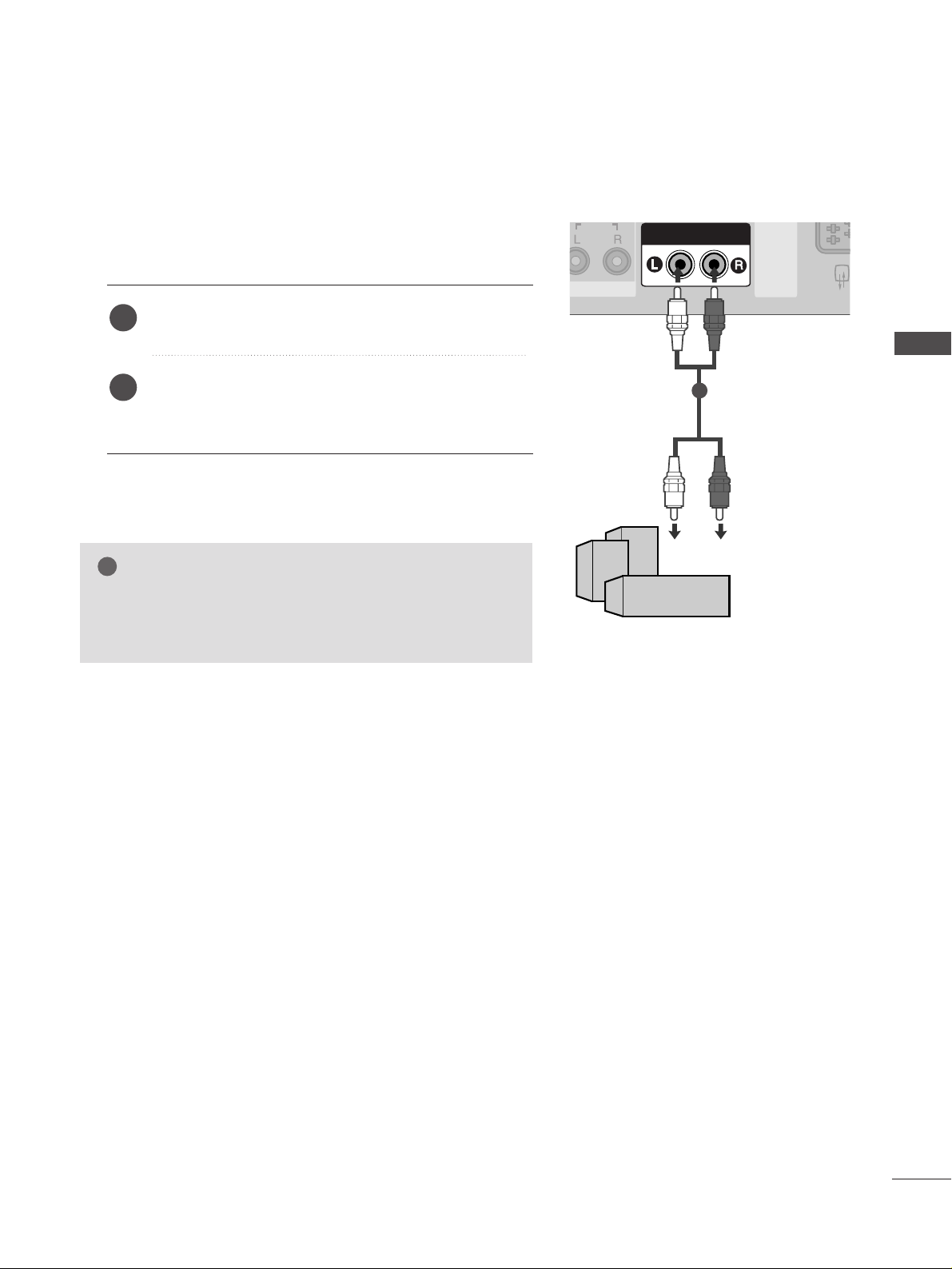
GG
When connecting with external audio equipments, such as
amplifiers or speakers, please turn the TV speakers off.
(
GG
pp..9922
)
NOTE
!
Use to connected either an external amplifier, or add a subwoofer to your surround sound system.
Connect the input jack of the stereo amplifier to the
VVAARRII AABBLLEE AAUU DDIIOO OO UUTT
jacks on the set.
Set up your speakers through your analog stereo
amplifier, according to the instructions provided with
the amplifier.
2
1
11
22
USB IN SETUP
EXTERNAL EQUIPMENT SETUP
EXTERNAL EQUIPMENT SETUP
USB INUSB IN
AV IN 3
L/MONO
R
AUDIOAUDIO
S-VIDEO
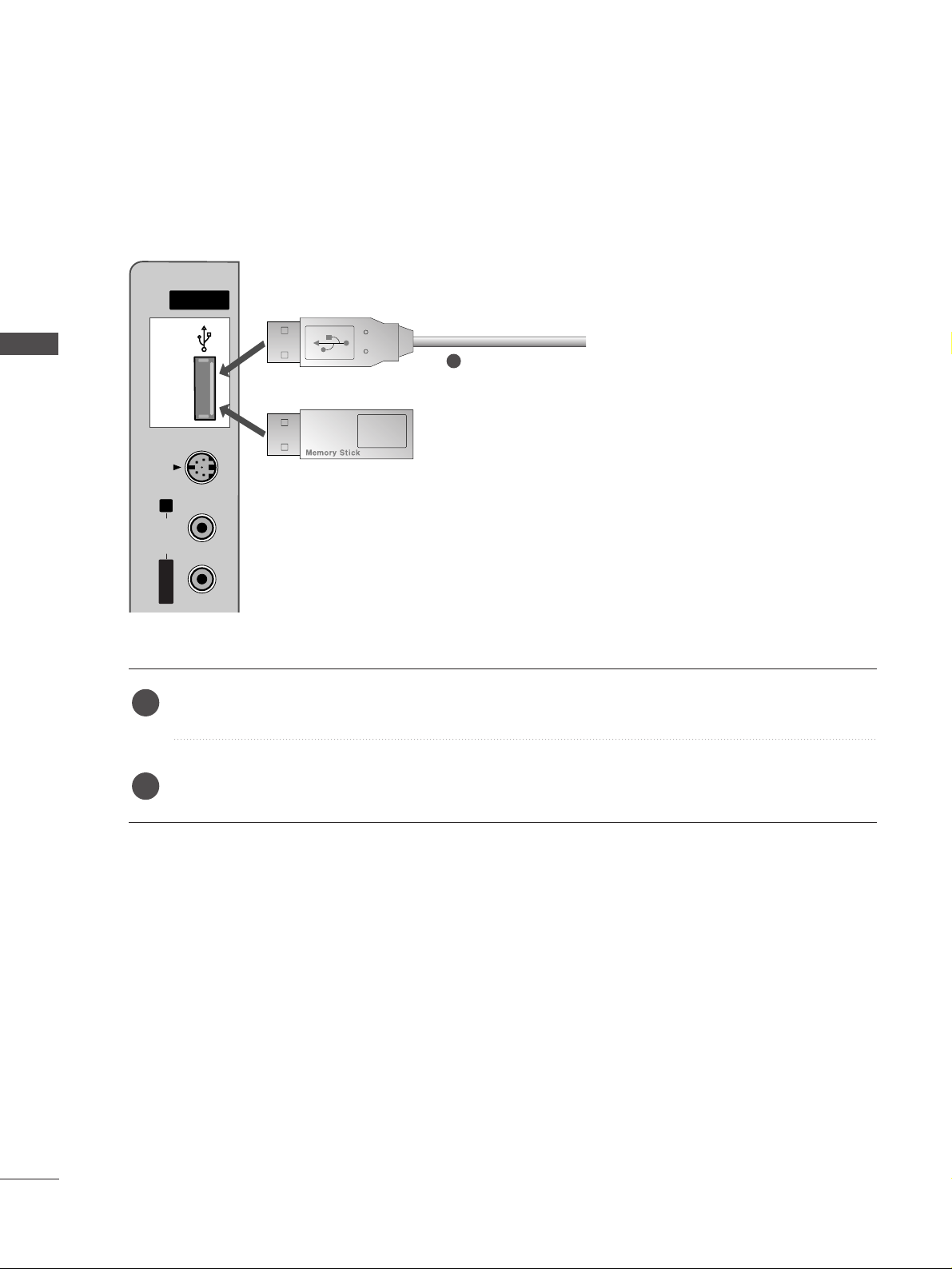
or
Connect the USB device to the
UUSSBB II NN
jacks on the side of TV.
After connecting the
UUSSBB II NN
jacks, you use the
DDVVRR
function. (
GG
pp..5544
)
2
1
1
23
PC SETUP
EXTERNAL EQUIPMENT SETUP
HDMI IN HDMI IN HDMI/DVI IN HDMI/DVI IN
12
VARIABLE AUDIO OUT
COMPONENT INCOMPONENT IN
AUDIO
VIDEO
AUDIO
(RGB/DVI)
RGB
(PC)
RGB IN
RS-232C IN
(CONTROL&SERVICE)
RS-232C IN
(CONTROL&SERVICE)
ANTENNA
IN
ANTENNA
IN
RGB
(PC)
AUDIO
(RGB/DVI)
RGB INRGB IN
RGB OUTPUT
AUDIO
1
2
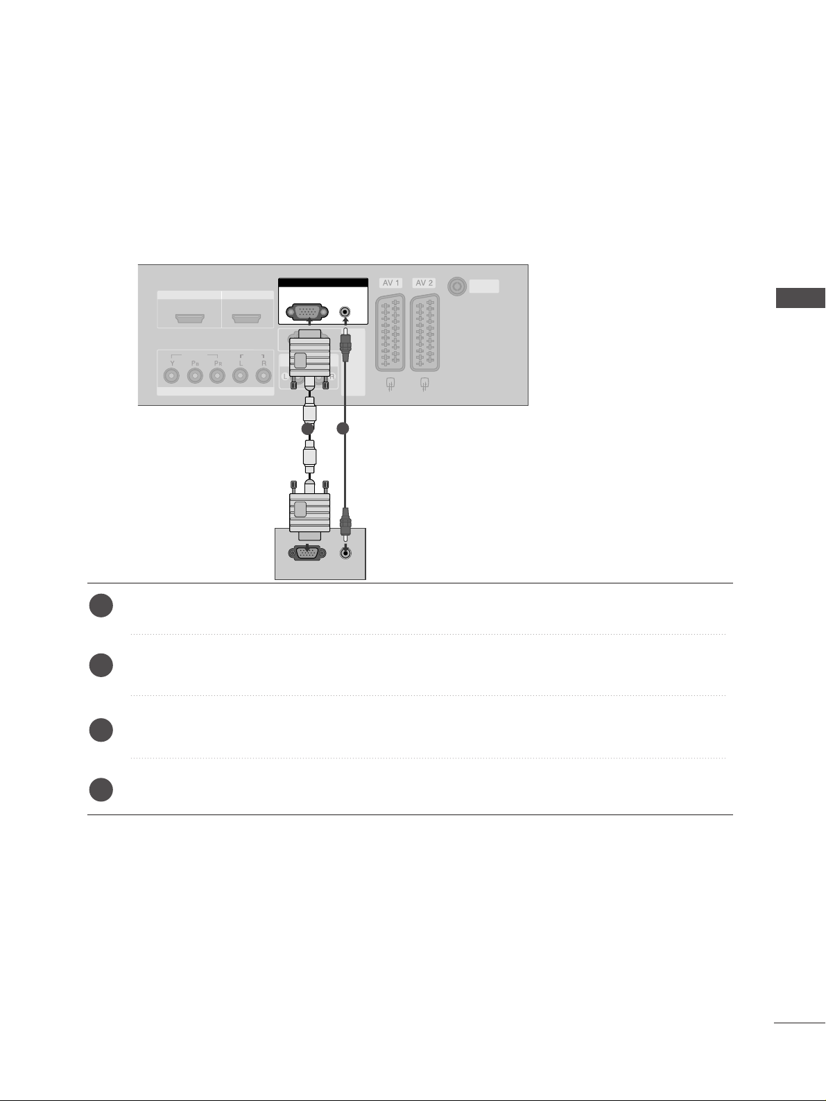
This TV provides Plug and Play capability, meaning that the PC adjusts automatically to the TV's settings.
When connecting with a D-sub 15 pin cable
Connect the RGB output of the PC to the
RRGGBB ((PPCC
))
jack on the set.
Connect the PC audio output to the
AAUU DDIIOO((RRGGBB //DD VVII))
jack on the set.
Turn on the PC and the set.
Select
RGB input source with using the
IINNPPUUTT
button on the remote control.
2
3
4
1
EXTERNAL EQUIPMENT SETUP
24
EXTERNAL EQUIPMENT SETUP
When connecting with a HDMI to DVI cable
HDMI IN HDMI IN HDMI/DVI IN HDMI/DVI IN
12
VARIABLE AUDIO OUT
COMPONENT INCOMPONENT IN
AUDIO
VIDEO
AUDIO
(RGB/DVI)
RGB
(PC)
RGB IN
RS-232C IN
(CONTROL&SERVICE)
RS-232C IN
(CONTROL&SERVICE)
ANTENNA
IN
ANTENNA
IN
HDMI/DVI IN
1
RGB IN
RGB IN
DVI-PC OUTPUT
AUDI O
1
2
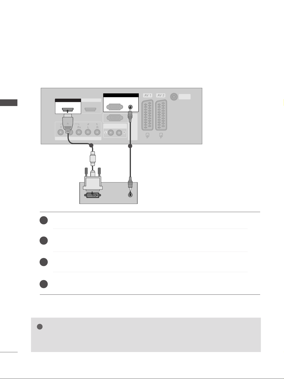
Connect the DVI output of the PC to the
HHDDMMII//DD VVII IINN 11
jack on the set.
Connect the PC audio output to the
AAUU DDIIOO((RRGGBB //DD VVII))
jack on the set.
Turn on the PC and the set.
Select
HDMI1/DVI input source with using the
IINNPPUUTT
button on the remote control.
2
3
4
1
GG
If the PC has a DVI output and no HDMI output, a separated audio connection is necessary.
GG
If the PC does not support Auto DVI, you need to set the output resolution appropriately.
NOTE
!
EXTERNAL EQUIPMENT SETUP
25
NOTE
!
G
To enjoy vivid picture and sound, connect a PC to
the set.
G
Avoid keeping a fixed image on the set’s screen for
a long period of time. The fixed image may become
permanently imprinted on the screen; use a screen
saver when possible.
G
Connect PC to the RGB (PC) or HDMI IN (or
HDMI/DVI IN) port of the set; change the resolution output of PC accordingly.
G
There might be noise according to some resolution,
vertical pattern, contrast or brightness in PC mode.
Change the PC mode into another resolution or
change the refresh rate into another rate or adjust
the brightness and contrast on the menu until the
picture is clean. If the refresh rate of the PC graphic card can not be changed, change the PC graphic
card or consult it to the manufacturer of the PC
graphic card.
G
The synchronization input waveform for Horizontal
and Vertical frequencies are separate.
G
We recommend using 1024x768, 60Hz (42 inch PLASMA TV models)/ 1360x768, 60Hz (50 inch PLASMA TV
models) for the PC mode, they provide the best picture
quality.
G
Connect the signal cable from the monitor output
port of the PC to the RGB (PC/DTV) port of the
set or the signal cable from the HDMI output port
of the PC to the HDMI IN (or HDMI/DVI IN) port
on the set.
G
Connect the audio cable from the PC to the Audio
input on the set. (Audio cables are not included
with the set).
G
If using a sound card, adjust PC sound as required.
G
This set uses a VESA Plug and Play Solution. The
set provides EDID data to the PC system with a
DDC protocol. The PC adjusts automatically when
using this set.
G
DDC protocol is preset for RGB (Analog RGB) and
HDMI (Digital RGB)
mode.
G
If required, adjust the settings for Plug and Play
functionally.
G
If graphic card on the PC does not output analog
and digital RGB simultaneously, connect only one of
either RGB or HDMI IN (or HDMI/DVI IN) to display the PC on the set.
G
If graphic card on the PC does output analog and
digital RGB simultaneously, set the set to either
RGB or HDMI; (the other mode is set to Plug and
Play automatically by the set.)
G
DOS mode may not work depending on video card
if you use a HDMI to DVI cable.
G
When you use too long RGB-PC cable, there might
be a noise on the screen. We recommend using
under 5m of the cable. It provides the best picture
quality.
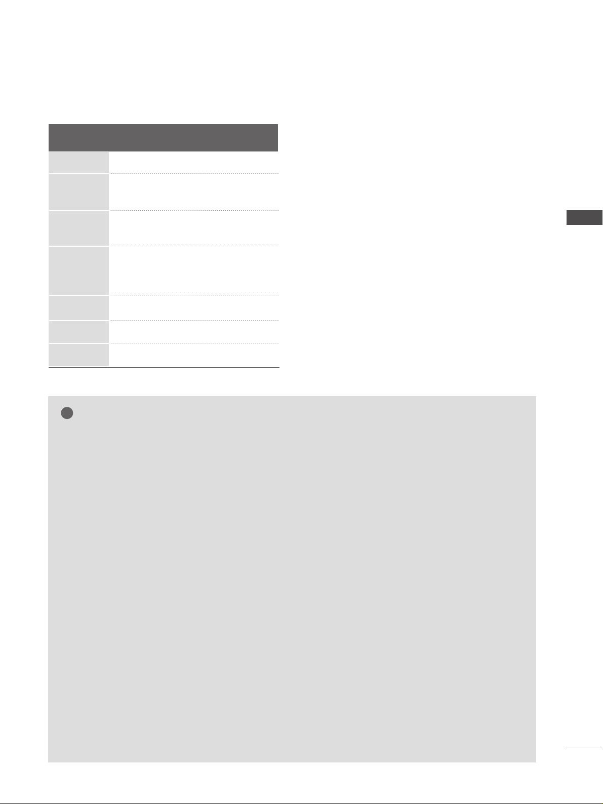
Supported Display Resolution (RGB /HDMI[PC]mode)
Resolution
720x400
640x480
800x600
1024x768
1280x768
1360x768
1366x768
31.469 70.08
31.469 59.94
37.500 75.00
37.879 60.31
46.875 75.00
48.363 60.00
56.476 70.06
60.023 75.02
47.693 59.99
47.700 60.00
47.700 60.00
Horizontal
Frequency(kHz)
Vertical
Frequency(Hz)
EXTERNAL EQUIPMENT SETUP
26
EXTERNAL EQUIPMENT SETUP
Screen Setup for PC mode
Picture Mode
Colour Temperature
Advanced
Aspect Ratio
Picture Reset
Screen
Demo
SETUP
O
AUDIO
O
TIME
O
OPTION
O
PICTURE G
Prev.
Menu
DVR
O
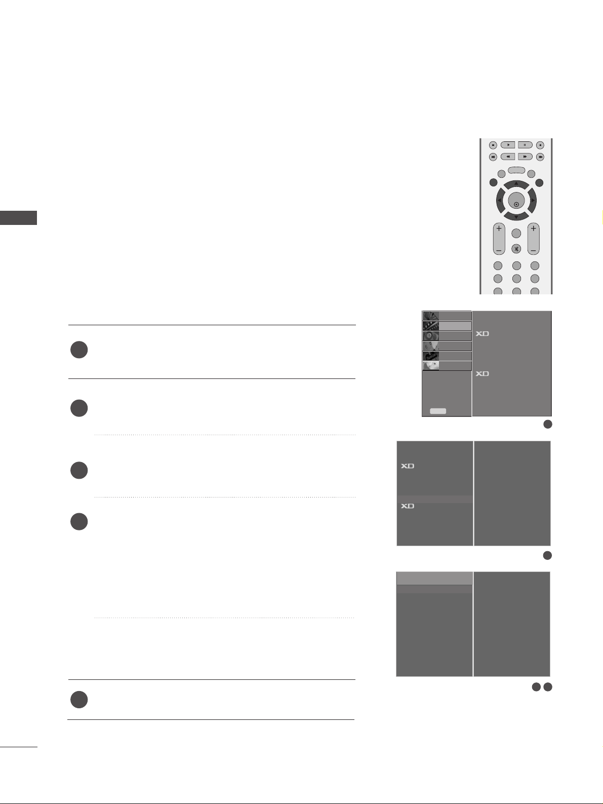
Press the
MMEENN UU
button and then use
DD
//
EE
button to
select the
PICTURE menu.
Press the
GG
button and then use
DD
//
EE
button to select
Screen.
Press the
GG
button and then use
DD
//
EE
button to select
Auto Config..
Press the
GG
button to start Auto Config..
• When
AAuuttoo ccoonnffii gg..
has finished, OK will be shown on
screen.
• If the position of the image is still not correct, try Auto
adjustment again.
• If picture needs to be adjusted more after Auto adjustment in RGB, you can adjust the
Manual Config..
Press the
EEXXIITT
button to return to TV viewing.
Automatically adjusts picture position and minimizes image
shaking.After adjustment, if the image is still not correct, your
set is functioning properly but needs further adjustment.
AAuuttoo ccoo nn ffiigguurree
This function is for the automatic adjustment of the screen
position, clock, and phase. The displayed image will unstable for
a few seconds while the auto configuration is in progress.
1
2
3
4
5
Auto Configure (RGB mode only)
1
3 4
2
To Set
Auto Config. G
Manual Config.
XGA Mode
Reset
To Set
Picture Mode
Colour Temperature
Advanced
Aspect Ratio
Picture Reset
Screen
G
Demo
OK
MENU
VOL PR
EXIT
TIME
SHIFT
TIME
SHIFT
LIST
LIVE TV
123
456
789
FAV/
MARK
MUTE
6
DVR
Screen
27
EXTERNAL EQUIPMENT SETUP
Picture Mode
Colour Temperature
Advanced
Aspect Ratio
Picture Reset
Screen
Demo
SETUP
O
AUDIO
O
TIME
O
OPTION
O
PICTURE G
Prev.
Menu
DVR
O
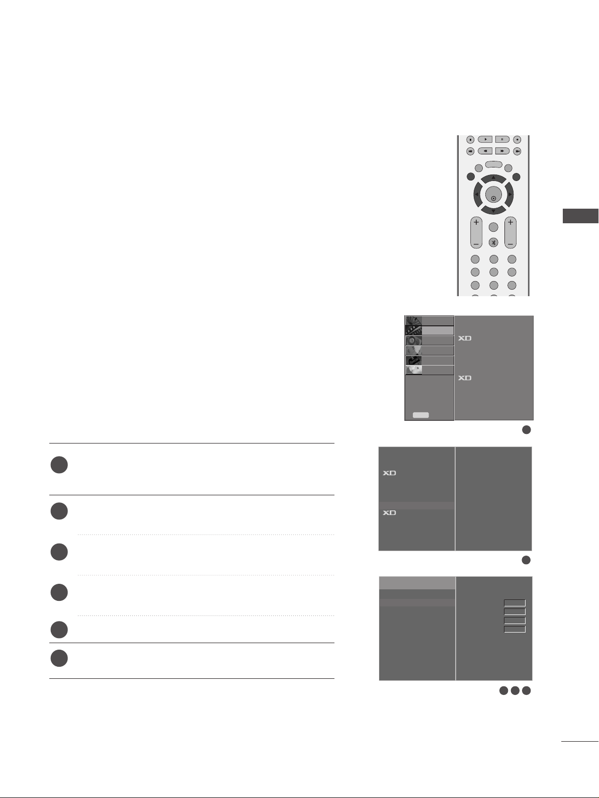
If the picture isn’t clear after auto adjustment and especially if
characters are still trembling, adjust the picture phase manually.
To correct the screen size, adjust
CC lloocckk
.
This function works in the following mode : RGB, COMPONENT
(480p/576p/720p/1080i/1080p), HDMI
(480p/576p/720p/1080i/1080p).
It’s not available to use Phase, Clock function in COMPONENT
(480p/576p/720p/1080i/1080p), HDMI
(480p/576p/720p/1080i/1080p).
CC lloocckk
This function is to minimize any vertical bars or stripes
visible on the screen background. And the horizontal
screen size will also change.
PPhhaassee
This function allows you to remove any horizontal noise
and clear or sharpen the image of characters.
Press the
MMEENN UU
button and then use
DD
//
EE
button to
select the
PICTURE menu.
Press the
GG
button and then use
DD
//
EE
button to select
Screen.
Press the
GG
button and then use
DD
//
EE
button to select
Manual Config..
Press the
GG
button and then use
DD
//
EE
button to select
Phase, Clock, H-Position or V-Position.
Press the
FF
//
GG
button to make appropriate adjustments.
Press the
EEXXIITT
button to return to TV viewing.
1
2
3
4
5
6
Adjustment for screen Phase, Clock, Position
1
3 4 5
2
To Set
Auto Config.
Manual Config.
G
XGA Mode
Reset
Phase
Clock
H-Position
V-Position
0
0
0
0
Picture Mode
Colour Temperature
Advanced
Aspect Ratio
Picture Reset
Screen
G
Demo
OK
MENU
VOL PR
EXIT
TIME
SHIFT
TIME
SHIFT
LIST
LIVE TV
123
456
789
FAV/
MARK
MUTE
6
DVR
Screen
28
EXTERNAL EQUIPMENT SETUP
EXTERNAL EQUIPMENT SETUP
Picture Mode
Colour Temperature
Advanced
Aspect Ratio
Picture Reset
Screen
Demo
SETUP
O
AUDIO
O
TIME
O
OPTION
O
PICTURE G
Prev.
Menu
DVR
O
To see a normal picture, match the resolution of RGB mode and
selection of XGA mode.
This function works in the following mode: RGB mode.
Press the
MMEENN UU
button and then use
DD
//
EE
button to
select the
PICTURE menu.
Press the
GG
button and then use
DD
//
EE
button to select
Screen.
Press the
GG
button and then use
DD
//
EE
button to select
XGA Mode.
Press the
GG
button and then use
DD
//
EE
button to select
the desired XGA resolution.
Press the
EEXXIITT
button to return to TV viewing.
Selecting Wide XGA mode
1
2
3
4
5
1
3 4
2
To Set
Auto Config.
Manual Config.
XGA Mode
G
Reset
1024 X 768
1280 X 768
1360 X 768
1366 X 768
Picture Mode
Colour Temperature
Advanced
Aspect Ratio
Picture Reset
Screen
G
Demo
OK
MENU
VOL PR
EXIT
TIME
SHIFT
TIME
SHIFT
LIST
LIVE TV
FAV/
MARK
MUTE
DVR
Screen
 Loading...