

LG 42PM11 - MU - 42"" Plasma Panel, MU-42PM11, MU-42PM12X, MU-50PM10 Owner's Manual

SMANUAL
MODELS • MU-42PM11/12X
iiiiiiiiiii_iiiiiiiiiiiiiiiiiiiiiiiiiiiiiiiiiiiiiiiiiiiiiiiiiiiiiiiiiiiiiiiiiiiiiiiiiiiiiiiiiiiiiiiiiiiiiiiiiiiiiiiiiiiiiiiiiiiiiii_i_i_.............
_fore _rating
_itor a_ relate
ser¢_e,
Warning/Caution
m
ion
WARNING/CAUTION:
TO REDUCE THE RISK OF ELECTRIC SHOCK DO NOT REMOVE COVER (OR BACK)_ NO USER
SERWCEABLE PARTS INSIDE, REFER TO QUAUFIED SERVICE PERSONNEL.
the presence of uninsulated "dangerous voltage" within the pro,duct's enclosure that may be of suffi-
The lightning flash with arrowhead sym_l, within an equil_era[ triangle, is i_ended to alert the user to
cient magnitu_ to con_itute a risk of e_ectric shock to per_ns.
The exclamation point within an equilatera_ triangle is intended to alert the user to the presence of
im_rt_3nt operating and rr_3intenance (set.icing) instructions in the literature accompanying the appD
_ce.
WARNING/CAUTION:
TO PREVENT FIRE OR SHOCK HAZARDS, DO NOT EXPOSE THIS PRODUCT TO RAIN OR MOISTURE,
FCC NOTICE
. A Class B digital device
This equipment has been tested and found to comply with the _imits for a Class B digital device, pursuant to Part
_5 of the FCC Rules These limits are designed to provide reasonable protection against harmfut interferen_ in
a resi_ntial insta_tation_ This equipment generals, uses and can radiate radio frequency energy and, if not
installed and used in accordance with the instructions, may cause harmful interference to radio communications,
However, there is no guarantee that interference will not occur in a particular installation, ff this equipment does
cause harmful interference to radio or teievision reception, which c_ be determined by turning the equipment off
and on, the user is encouraged to t_, to correct the interference by one or more of the fo[iowing measures:
Reorient or relocate the re_iving antenna.
- Increase the separation between the equipment and receiver.
- Conn_t the equipment into _ outJet on a circuit differer_t from that to which the receiver is connected.
Consult the _aJer or an experienced radio/TV technician for heip
- Any changes or modifications not expressly approved by the party responsible for compli-
ance could void the user's authority to operate the equipment,
CAUTION:
Do not attempt to modify this product in any way without written authorization from LG Electronics. Unauthorizod
ification could void the user's authori_j to operate this product,
COMPLIANCE:
The responsibFe party for this product's compliance is:
LG Electronics U.S.A., Inc
1000 Sylvan Avenue, Englewood Cliffs, NJ 07632
1-201-816-_
http:/iw_,-w._gusa.com
WARNING/CAUTION
TO REDUCE THE RiSK OF FIRE AND ELECTRIC SHOCK, DO NOT EXPOSE THIS PRODUCT TO
RAiN OR MOISTURE
2 Plasma Monitor

Warning!Caution
ctions
Important safeguards for you and your new product
Your product has been manufactured and tested with your safety in mind, However, improper use can result in potential e[_-
trica[ shock or fire hazards, To avoid defeating the safeguards that have been buiJt into your new product, ptease read and
observe the foJtowiag safety points when installing and using your new product, and save them for future reference
Observing the simple precau_ons discussed in this bookJet can help you get many years of enjoyment and safe operation
that are built into your new product
This product complies with a_ applicable U.S, Federa_ safety requirements, _d those of the Canadian Standards
Association.
1, Read these instructions.
2. Keep these lnstructions_
3. Heed all warntngs_
4. Follow all instructions.
5. Do not use this apparatus near water.
6. Clean only with dry cloth.
7. DO not block any ventilation openings. Install in accordance with the manufacturer's instructions.
8. Do not install near any heat sources such as radiators, heat registers, stoves, or other apparatus (including ampli-
fiers)that produce heat.
9. Do not defeat the safety purpose of the _lari_d or groundlng4ype plug. A polarized plug has two blades with
one wider than the other. A grounding type plug has two blades and a third grounding prong, The wide blade or the
third prong are provided for your safety. If the provided plug does not f_ into your outlet, consult an electrician for
repIaeea'_nt of the obsolete outlet.
f0. Protect the power cord from _tng walked on or pinched particularly at plugs, convenience receptacles, and the
point where they exit from the apparatus.
Owner's Manual 3

SafetyInstructions
Safety Instructions continued
11, Only use attachments/a,ccessories specified by the m_nufacturer,
12. Use only with the cart, stand, tripod, bracket, or table specified by the manufacturer, or sold with the apparatus.
When a cart is used, use caution when moving the cart!apparatus combination to avoid injury from tip-over.
I::O_&BLE CART WARNING
13, Unplug this apparatus during lightning storms or when unused for long periods of time,
14, Refer all servicing to qualified service personnel, Servicing is requked when the apparatus has been damaged
in any way, such as power-supply cord or plug is damaged, liquid has b_n spilled or objects have fallen into the
apparatus, the apparatus has exposed to rain or moisture, does not oparate norma,y, or has b_n dropped,
15, Outdoor U_ Marking :
WARNING - To Reduce The Risk Of Fire Or Electric Shock, Do Not Expose This Appliance To Rain Or Moisture,
16, Wet Location Marking :
Apparatus shall not be exposed to dripping or splashing and no objects tilled with liquids, such as vases, shall
be placed on the apparatus.
J
4 Plasma Monitor

SafetyInstructions
Warning)Caution ............................. 2
Safety Instructions ....................... 3-4
Introd uction
Controls ................................. 7
Connection Options 8
Remote Controt Key Functions .......... 9
installation
Installation Instructions ................. 10-11
External Equipment Connections ........... 12~16
VCR Setup .................... 12
Cable TV Setup ..................... 12
External NV Source Setup ................ 13
DVD Setup ............................ 13
DTV Setup ............................ 14
PC Setup .......................... 15-16
Operation
Turning on the Monitor ............ 17
Menu t nnguage Selection .................. 17
Picture Menu Options
APC (Auto Picture Control) ................ 18
XD ............................... 18
Cotor Temperature Control ................ 18
Fteshtone ............................ 19
sRGB ................................ 19
Manual Picture Contro_(APC set to _ option)...19
Sound Menu Options
DASP (Digital Auto Sound Processing) ...... 20
BBE ...................... 20
AVL (Auto Volurr_ Leveler) ................ 20
Manual Sound Control (DASP set to Off option) , .21
Timer Menu Options
Clock Setup .......................... 22
On/Off Timer Setup .................... 22
Auto Off / Sleep T_mer ................. 22
Special Menu Options
Key Lock ..................... 23
_SM (Image Sticking Minimization) Method .... 23
Low Power ............................ 24
XD Demo ............................... 24
Menu Rotation for Vertical Viewing ......... 24
Screen Menu Options
Auto Adjustment .................... 25
Se_ng Picture Format ...................... 25
_reen Position ........................ 25
Manua_ Configure ......................... 26
Selecting VGA/XGA Mo_ .............. 26
Screen Adjust_nts .................. 26
Cinema Mode Setup ............... 26
Luminance Noise Reduction ............... 27
initializing (Reset to original factory va_ue) ..... 27
Split Zoom ............................ 27
PIP (Picture-lmPicture)/Doub_e Window Feature
Watching PIP/Double Window ............ 28
Swapping the PiP/Double Window .......... 28
SetedJng an Jn_ S_naf _se for PIP/D_Jble W_ .28
Moving the PIP(PIP Mode only) ............ 28
PIP Size 28
PIP Transparency (PIP Mode only) ........ 28
External Control Device Setup ................ 29~34
IR Code Information ....................... 35_36
Troubleshooting Checklist ...................... 37
Maintenance ................................. 38
Product Specifications ......................... 38
Warranty ................................. 39--40
After reading this manual, keep it handy for future reference,
Owner's Manual 5
introduction
I
Int
What is a Plasma Display Panel (PDP)?
If voltage is applied to gas within glass paners, ultraviolet rays are produced and fused with a fluorescentsubstance. At that
instant,right is emitted. A P_asmaDisplay is a next generation flat Display using this phenomenon.
160° - Wide angle range of vision
Your fl_ pane[ plasma screen Qffers an exseptiona_ly broad viewing angle ==over 160 degrees_This means that the display is
dear and visible to viewers who e_ see the screen anywhere in the room,
Wide Screen
The screen of the Ptasma Display is wide so that your viewing experience is as if you are in a theater
Multimedia
Connect your plasma display to a PC and you can use it for conferencing, games, and internet browsing. The Picture-in-Picture
feature allows you to view your PC and video images simultaneously.
Versatile
The _ightweight and thin size makes _teasy to install your plasma dJsptay in a variety of locations where conventional TVs would
not fit
IOn
The PDP Manufacturing Process: Why minute colored dots may be present on the PDP screen
The PDP (Ptasma Display Panel) which is the display device of this product is composed of 0_9 to 2,2 mii_ien sells, A few ceil
defe_ wiJ[ normally occur in the PDP manufacturing process, Several minutes colored dots visible on the screen should be
accep_[e, This a_so occurs in other PDP manuffac_rers' products and the tiny dots appearing does not mean that this PDP is
defec_ve Thus a few cell defects are not sufficient cause for the PDP to be exchanged or returned Our production technology is
designed to minimize sei_ defects during the manufacture and operation of this product,
Cooling Fan Noise
in the same way that a fan is used in a PC computer to keep the CPU (Central Processing Unit) cool, the PDP is equipped with
cooling fans to cool the Monitor and improve i_ reliability. Therefore, a certain level of noise could occur while the fans are operat-
ing and cooling the PDP,
The fan noise doesn't have any negative effect on the PDP's efficiency or reliability. The noise from these fans is normal during the
operation of this product. We hope you understand that a certain [eve[ of noise from the cooling fans is acceptable and is not suffi-
cient cause for the PDP to be exchanged or returned.
6 Plasma Monitor

-This is a simprified representa_on of a typical front panel.
The Front Panel Controls shown here may be _mewhat different from your monitor.
MU-42PM11/12X, 50PM10 series
Introduction
1, Main Power Button
2. Remote Control Sensor
3, Power Standby Ind_cator
I_lumina_es red in standby mode, Illuminates green when the Monitor is turned on,
4, INPUT SELECT Button
5= MENU
Displays on screen menus one by one,
Exits the current menu_
Memorizes menu changes_
6, AfV
Selects a menu option,
/ _ (Volume Up/Down)
Increases/decreases sound JeveL
Adjusts menu settjngs,
3 2
Owner's Manual 7
introduction
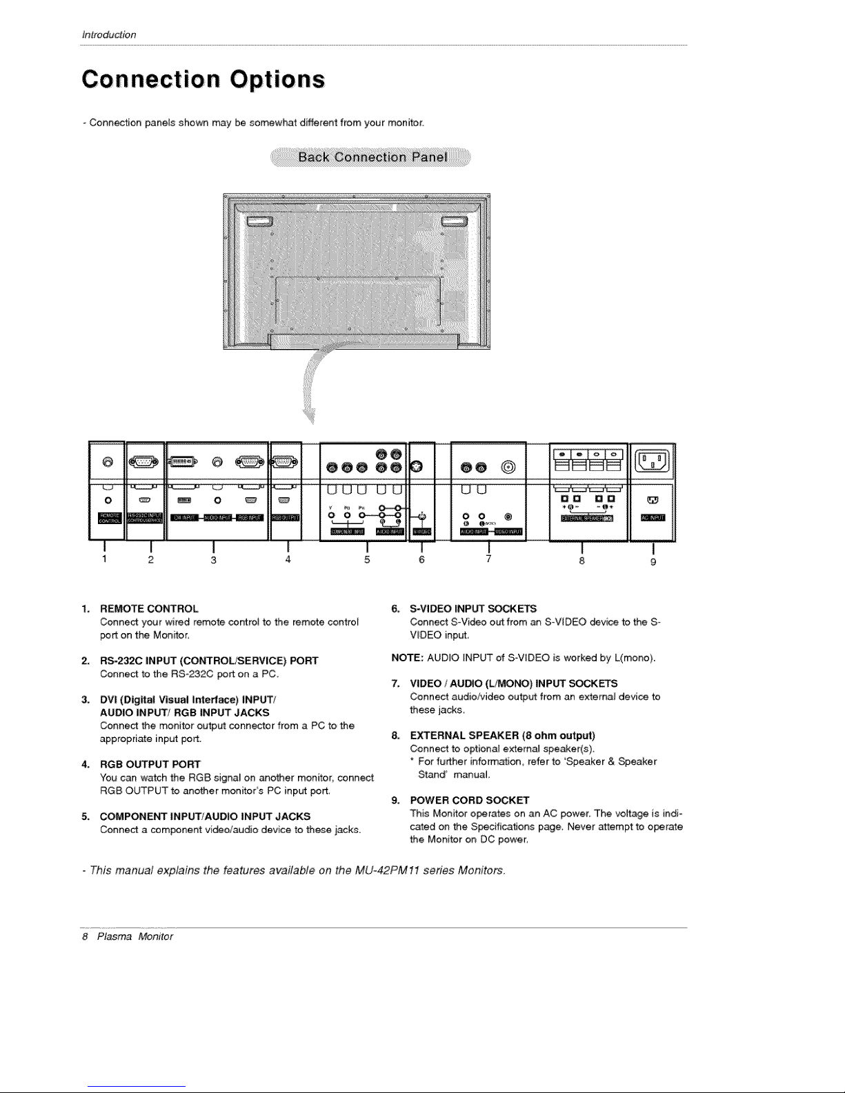
-Connection pane_s shown may be somewhat different from your monitor.
_ O e@@ @@ O @e O
OO
O _ _ O _
1 2 3 4 5 6 7
1.
REMOTE CONTROL
Conne_ your wired remote control to the remote control
port on the Men_or,
2,
RS-232C INPUT (CONTROL/SERVICE) PORT
Connect to the RS-232C port on a PC.
3_
DVI (Digital Visual Interf_e) |NPUTt
AUDIO INPUT/RGB INPUT JACKS
Connect the monitor output connector from a PC to the
appropriate input port.
4_
RGB OUTPUT PORT
You can watch the RG8 signal on ano_er monitor, connect
RG8 OUTPUT to another monitor's PC input port
5_
COMPONENT INPUT/AUDIO INPUT JACKS
Connect a component vi_oiaudio device to these jacks.
6, S-VIDEO _NP_ SC_I<_
Connect S-Video out from an S-VIDEO device to the S _
V_DEO input,
NOTE: AUDIO _NPUT of S-V[DEO is worked by L(mono).
7. VIDEO / AUtO (L/MO_) INPUT EKETS
Connect aud:ioi_ideo output from an external device to
these jacks.
EXTERNAL SPEAKER (8 ohm output)
Connect to optional external speWer(s).
* For further information, refer to 'Speaker & Speaker
Stand' manual,
g. POWER CORD S_KET
This Monitor operates on an AC power. The voltage is indi-
cated on the SpecificatJons page, Never attempt to operate
the Monitor on DC power:
O0 O0
m
i
8
This manual explains the features available on the MU-42PM11 series Monitors.
8 Plasma Monitor

Remote Control Key Functions
- When using the remote control, aim it at the remote control sensor on the n_nitor,
Under certain conditions such as if the remote IR signa[ is interrupted_ the remote contro_ may not function, Press
the key again as necessary.
Introduction
Switches the Monitor between \-\
POWER ....
ON _d STANDBY. "_.
SLEEP--...... "\\
Sets the S_eep T'_mer_ "---__ "
(Refer to p,22) ..... ._..
Adjusts the factory preset picture
according to the morn,
(Refer to p.18}
ARC J J/
Changes the picture format.
(Refer to p.25)
Switches the sub picture on or off.
(Refer
Exchanges main and sub picture
images, (Refer to p,28)
MENU
Displays on screen menus one by one.
Exits the current m_nu.
NUMBER buttons
DVD buttons
Control some DVD cassette
recorders,
POWER
INPUT SELECT
//Selects source: R_ DVI_
_-_--_'_'_S PLIT ZOOM
Component, Video, or SoVideo
mode.
j DASP
To select the sound appropriate to
your vie_ng program character:
SRS TSXT, Flat, Music, Movie_
Sp,o_s, or Oil (Refer to p.2O)
Enlarges the picture.
WlN._SfflON
Moves the sub picture.
Se[_ the input source for the sub
pictu re.
MUTE
Switches the sound on or off.
OK
A_V
_lects menu option
Memorizes menu changes,
/J_ (Volume button)
increases,/decrea_s soand teveL
Adjusts menu settings,
WIN,SIZE
Adjusts the sub picture size,
VCR 8 bq-rONS
Control some video cassette
recorders,
* Open the battery compartment cover on the back side and
insert the batteries with correct polarity,
- Ins_H two 1,5V a_kaline batteries of AAA ty_ Don't mix used
batteries with new bakeries,
Owner's Manual 9
tnstaltalion
II
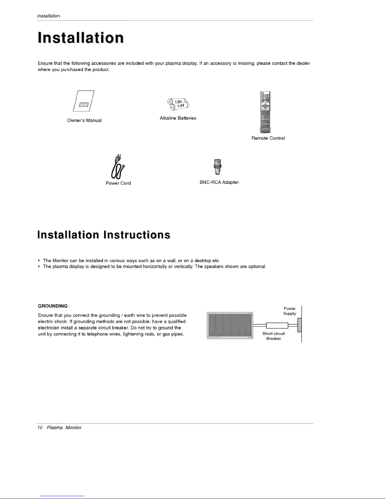
Ensure that the foJlowing accessories are inc[u_d with your plasma disptay If an accessory is missing, please con_ct the denier
where you purchased the product
Owner's Manual
Power Cord BNC*RCA Adapter
AlkaJine Batteries
Remote Control
Installation Instructions
• The Monitor can _ installed in various ways such as on a wal_, or on a desktop etc,
• The ptasma display is designed to _ mounted horizontally or vertically. The speakers shown are optional
GROUNDING
Ensure that you connect the grounding / earth wire to prevent possibJe
electric shock If grounding rr_thods are not poss[Me, have a qualified
electrician instil a separate circuit breaker. Do not try to ground the
unit by connecting it to telephone wires, lightening rods, or gas pipes
10 Plasma Monitor
Power
SuppJy
Sho_-drcuit
Breaker
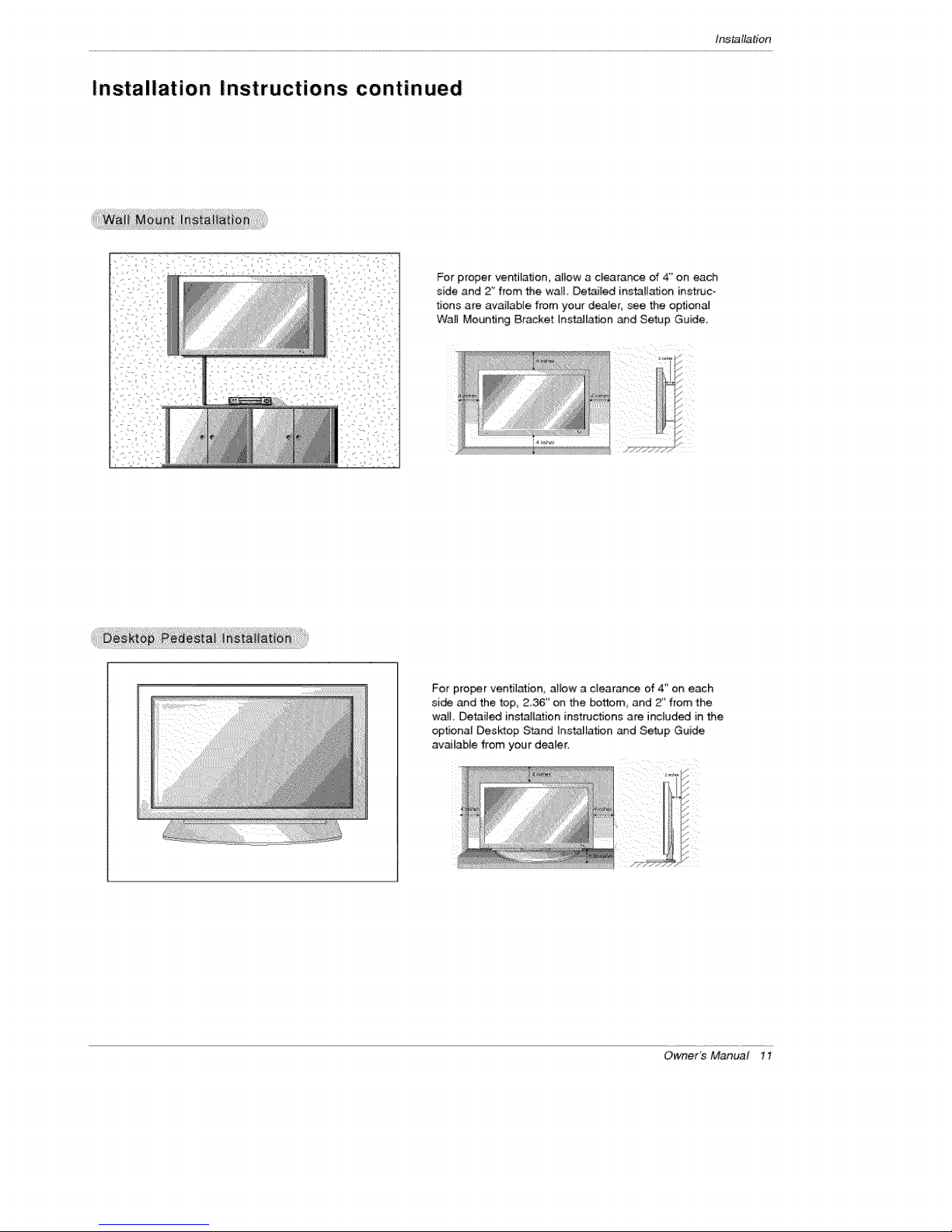
Installation Instructions continued
tns_llation
For proper ventilation, allow a clearance of 4 '_on each
side and 2" from the wall Detai_ed installation instruc_
t[ons are available from your dealer, see the optional
Wall Mounting Bracket Installation _d Setup Guide.
For proper ventilation, allow a clearance of 4_' on each
si_ and the top, 236" on the bottom, and Z' from the
wait Detailed installation instructions are included in the
optional Desktop Stand Installation and Setup Guide
available from your dealer,
Owner's Manual 11
tnstaltalion
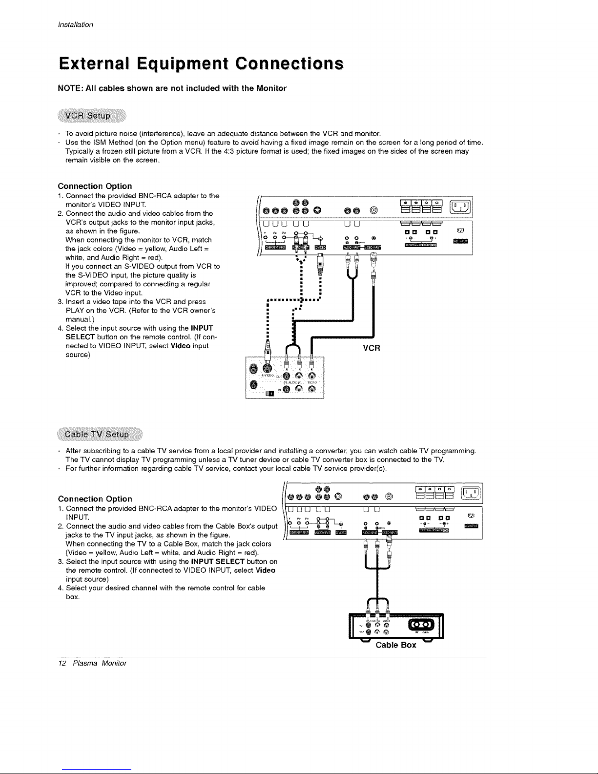
External Equipment Connections
NOTE: All cables shown are not included with the Monitor
- To avoid picture noise (interference), leave an adequate dis_ce between the VCR and monitor.
- Use the tSM Method (on the Option menu) feature to avoid having a fixed image rerr_in on the screen for a long period of time.
Typically a frozen stil_ picture from a VCR. If the 4:3 picture format is used; the fixed images on the sides of the screen may
remain visible on the screen.
Connection Option
1. Connect the provided BNC-RCA adapter to the
monitor's VIDEO iNPUT.
2. Connect the audio and video cables from the
VCR's output jacks to the monitor input jacks,
as shown in _e figure.
When connecting the monitor to VCR, match
the jack colors (Video =yetiow, Audio Left =
white, and Audio Right = red).
if you connect an S-WDEO output from VCR to
the S-VqDEO input, the picture quality is
improved; compared to connecting a regular
VCR to the Video input.
3. insert a video tape into the VCR and press
PLAY on the VCR. (Refer to the VCR owneCs
manuaL)
4. _lect the input source with using the iNPUT
SELECT button on the remote control (ff con-
nected to VIDEO INPUT, setect Video input
source)
VCR
After subscribing to a cable TV service from a local provider and installing a converter; you can w_ch came TV programming.
The TV cannot display TV programming unless a TV tuner device or cable TV converter box is connected to the TV,
For further info_ation regarding cable TV service, contact your local cable TV service provider(s).
Connection Option
1. Connect the provided BNC-RCA adapter to the monitor's VIDEO
INPUT.
2. Connect the audio and video cabtes from the Cable Box's output
jacks to the TV input jacks, as shown in the figure.
When connecting the TV to a Cable Box, match the jack colors
(Video = ye_tow, Audio Left = white, and Audio Right = red).
3. Select the input source with using the INPUT SELECT button on
the remote control. (ff connected to VIDEO INPUT, select Video
input source)
4. Select your desired channel with the remote control for came
box.
12 Plasma Monitor
U U _ "
0 O @ +Q- -e÷
Cable Box
 Loading...