

Page 1

PLASMA TV
SERVICE MANUAL
CAUTION
BEFORE SERVICING THE CHASSIS,
READ THE SAFETY PRECAUTIONS IN THIS MANUAL.
CHASSIS : PU01A
MODEL : 42PJ250 42PJ250-UA
42PJ250 42PJ250-UB
North/Latin America http://aic.lgservice.com
Europe/Africa http://eic.lgservice.com
Asia/Oceania http://biz.lgservice.com
Internal Use Only
P/NO : MFL62881509 (1004-REV00) Printed in Korea
Page 2

- 2 -
LGE Internal Use OnlyCopyright ©2010 LG Electronics Inc. All rights reserved.
Only for training and service purposes
CONTENTS
CONTENTS ............................................................................................................................... 2
SAFETY PRECAUTIONS ...........................................................................................................3
SPECIFICATION.........................................................................................................................4
ADJUSTMENT INSTRUCTION ..................................................................................................9
TROUBLE SHOOTING GUIDE ................................................................................................14
BLOCK DIAGRAM ...................................................................................................................46
EXPLODED VIEW ..................................................................................................................47
SVC. SHEET ................................................................................................................................
Page 3
- 3 -
LGE Internal Use OnlyCopyright ©2010 LG Electronics Inc. All rights reserved.
Only for training and service purposes
SAFETY PRECAUTIONS
Many electrical and mechanical parts in this chassis have special safety-related characteristics. These parts are identified by in
the Schematic Diagram and Exploded View.
It is essential that these special safety parts should be replaced with the same components as recommended in this manual to
prevent X-RADIATION, Shock, Fire, or other Hazards.
Do not modify the original design without permission of manufacturer.
General Guidance
An isolation Transformer should always be used during the
servicing of a receiver whose chassis is not isolated from the AC
power line. Use a transformer of adequate power rating as this
protects the technician from accidents resulting in personal injury
from electrical shocks.
It will also protect the receiver and it's components from being
damaged by accidental shorts of the circuitry that may be
inadvertently introduced during the service operation.
If any fuse (or Fusible Resistor) in this monitor is blown, replace it
with the specified.
When replacing a high wattage resistor (Oxide Metal Film
Resistor, over 1W), keep the resistor 10mm away from PCB.
Keep wires away from high voltage or high temperature parts.
Due to high vacuum and large surface area of picture tube,
extreme care should be used in handling the Picture Tube.
Do not lift the Picture tube by it's Neck.
Leakage Current Cold Check(Antenna Cold Check)
With the instrument AC plug removed from AC source, connect
an electrical jumper across the two AC plug prongs. Place the
AC switch in the on position, connect one lead of ohm-meter to
the AC plug prongs tied together and touch other ohm-meter
lead in turn to each exposed metallic parts such as antenna
terminals, phone jacks, etc.
If the exposed metallic part has a return path to the chassis, the
measured resistance should be between 1MΩ and 5.2MΩ.
When the exposed metal has no return path to the chassis the
reading must be infinite.
An other abnormality exists that must be corrected before the
receiver is returned to the customer.
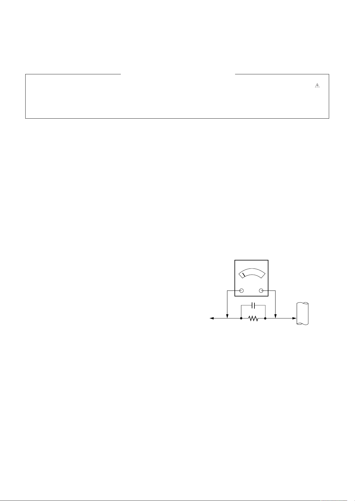
Leakage Current Hot Check (See below Figure)
Plug the AC cord directly into the AC outlet.
Do not use a line Isolation Transformer during this check.
Connect 1.5K/10watt resistor in parallel with a 0.15uF capacitor
between a known good earth ground (Water Pipe, Conduit, etc.)
and the exposed metallic parts.
Measure the AC voltage across the resistor using AC voltmeter
with 1000 ohms/volt or more sensitivity.
Reverse plug the AC cord into the AC outlet and repeat AC
voltage measurements for each exposed metallic part. Any
voltage measured must not exceed 0.75 volt RMS which is
corresponds to 0.5mA.
In case any measurement is out of the limits specified, there is
possibility of shock hazard and the set must be checked and
repaired before it is returned to the customer.
Leakage Current Hot Check circuit
1.5 Kohm/10W
To Instrument's
exposed
METALLIC PARTS
Good Earth Ground
such as WATER PIPE,
CONDUIT etc.
AC Volt-meter
IMPORTANT SAFETY NOTICE
0.15uF
Page 4
- 4 -
LGE Internal Use OnlyCopyright ©2010 LG Electronics Inc. All rights reserved.
Only for training and service purposes
SPECIFICATIONS
NOTE : Specifications and others are subject to change without notice for improvement
.
1. Application Range
(1) This spec sheet is applied all of PDP TV with PU01A chassis.
(2) Not included spec and each product spec in this spec sheet apply correspondingly to the following each country
2. Specification
Each part is tested as below without special appointment.
(1) Temperature : 20 °C ± 5 °C
(2) Relative Humidity : 65 % ± 10 %
(3) Power Voltage : Standard input voltage (100 V ~ 240 V @ 50/60Hz)
* Standard Voltage of each product is marked by models
(4) Specification and performance of each parts are followed each drawing and specification by part number in accordance with
BOM.
(5) The receiver must be operated for about 5 minutes prior to the adjustment.<-DQA Request
3. Test Method
(1) Performance : LGE TV test method followed.
(2) Demanded other specification
Safety : UL, CSA, IEC,CE specification
EMC : FCC, ICES, IEC, CE specification
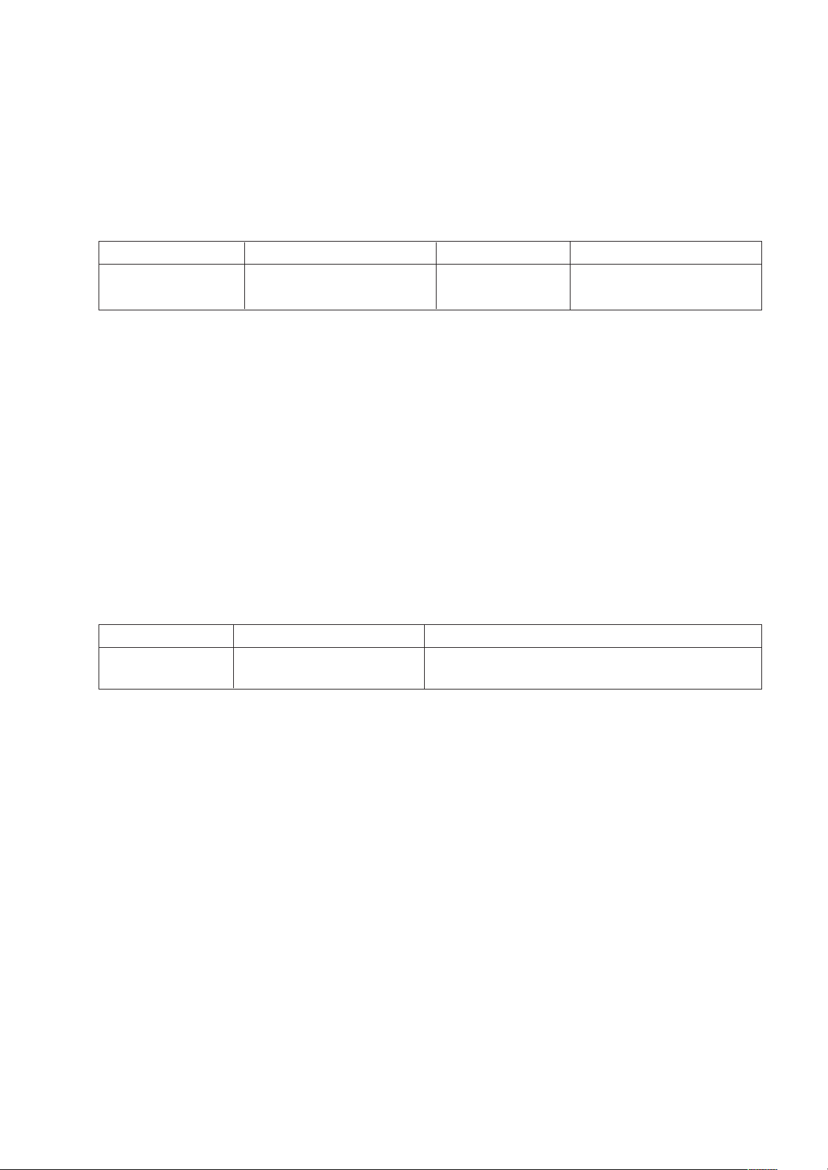
Model Name
42PJ250-UA
42PJ250-UB
Remark
Safety : UL1492, CSA C22.2.No.1
EMC : FCC Class B, IC Class B
Market
NORTH AMERICA
Model Name
42PJ250-UA
42PJ250-UB
Brand
LG
Market
NORTH AMERICA
Remark
PDP 42T1
Page 5
- 6 -
LGE Internal Use OnlyCopyright ©2010 LG Electronics Inc. All rights reserved.
Only for training and service purposes
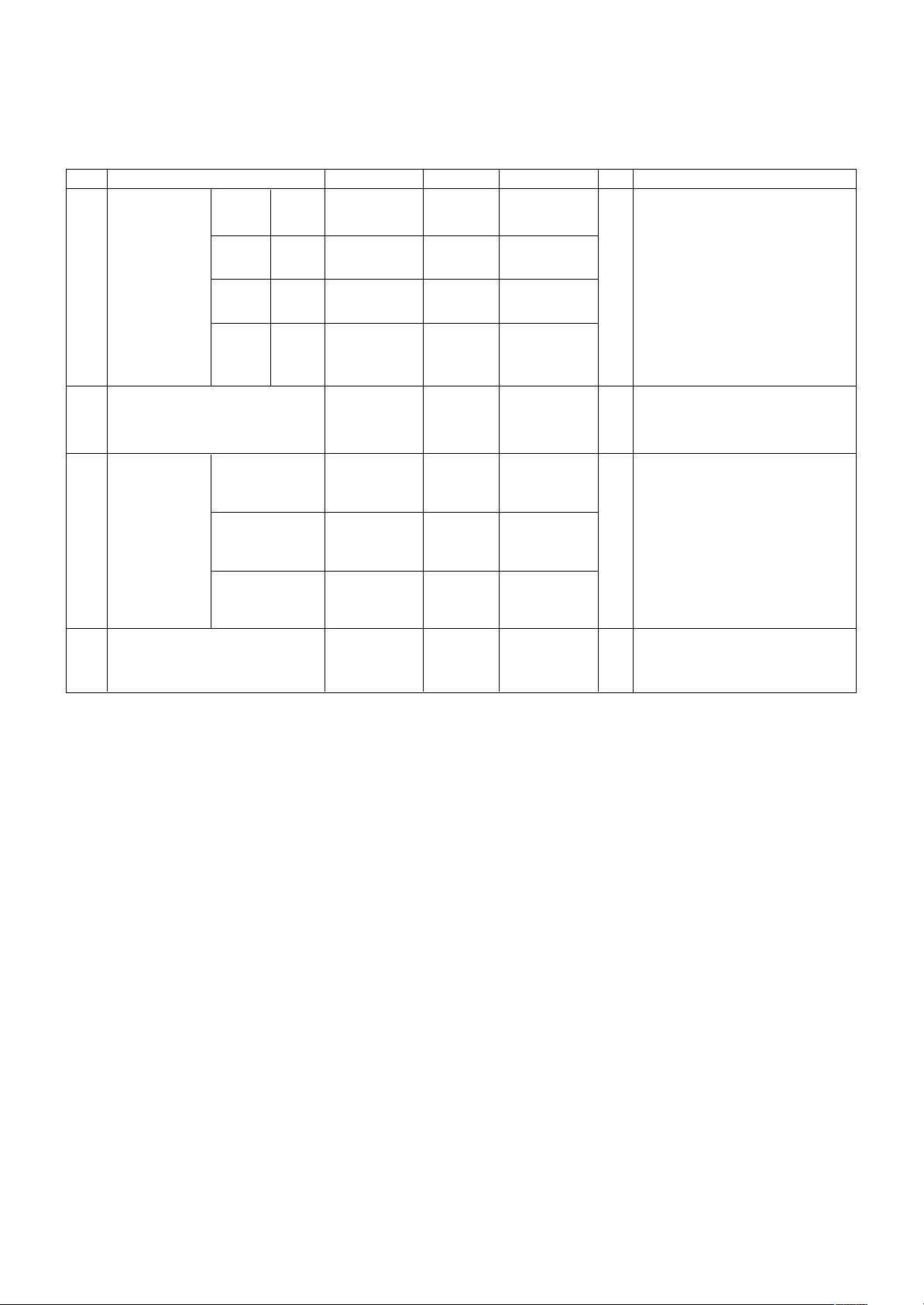
5. Chroma
(1) 42T1, 50T1, 50R1, 60R1 Module
No Item Min Typ Max Unit Remark
1 Color White X 0.270 0.285 0.300 08.11.20 Xrange change +-0.015
coordinate Y 0.283 0.293 0.303 09.10.13 blue Y Change
Red X 0.635 0.640 Unlimitedness 0.065~0.075
Y 0.318 0.330 0.345 - White : 85IRE(216Gray) 100%
Green X 0.242 0.300 0.305 100% Window White Pattern
Y 0.595 0.600 Unlimitedness - R/G/B : 100IRE(255Gray)
Blue X Unlimitedness 0.150 0.158
100% Window White Pattern
Y Unlimitedness 0.065 0.075
- Picture: Vivid(Medium )
- 100% Window
2 - 85IRE 100% Window White
Color coordinate uniformity -0.020 average +0.020 Pattern
- Picture: Vivid(Medium)
3 Color
Cool 0.261 0.276 0.291
- White : 85IRE(216Gray) 100%
Temperature
0.268 0.283 0.298
Window White Pattern
Medium 0.270 0.285 0.300
- 100% Window
0.278 0.293 0.308
08.11.20 range change +-0.015
Warm : ColorGamut => WIDE
Warm
0.298
0.313 0.328
Cool:Color temperature C30
0.314 0.329 0.344
Meduum:Color temperature 0
Warm:Color temperature W30
- - 85IRE(216Gray) 100% Window
4 Brightness uniformity -10 0 +10 % White Pattern
- Picture: Vivid(Medium)
Page 6
- 5 -
LGE Internal Use OnlyCopyright ©2010 LG Electronics Inc. All rights reserved.
Only for training and service purposes
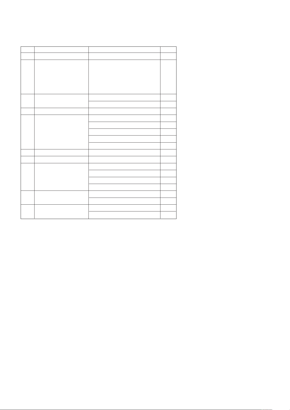
4. General Specification
No Item Specification Remark
1. Receiving System 1) ATSC/64 & 256 QAM/ NTSC-M
2. Available Channel 1) VHF : 02~13
2) UHF : 14~69
3) DTV : 02-69
4) CATV : 01~135
5) CADTV : 01~135
3. Input Voltage 1) AC 100 V ~ 240 V 50/60Hz
2) AC 100 V ~ 120 V 50/60Hz
4. Market NORTH AMERICA
5. Screen Size 106 cm (42 inch) Wide(1024 × 768) 42T1
127 cm (50 inch) Wide(1365 × 768) 50T1
152 cm (60 inch) Wide(1365 × 768)
127 cm (50 inch) Wide(1920 × 1080) 50R1
152 cm (60 inch) Wide(1920 × 1080) 60R1
6. Aspect Ratio 16:9
7. Tuning System FS
8. PDP Module PDP42T1#### (1024 × 768)
PDP50T1#### (1365 × 768)
PDP50R1#### (1920 × 1080)
PDP60R1#### (1920 × 1080)
9. Operating Environment 1) Temp : 0 deg ~ 40 deg
2) Humidity : ~ 80 %
10. Storage Environment 1) Temp : -20 deg ~ 60 deg
2) Humidity : 0 % ~ 90 %
Page 7
- 7 -
LGE Internal Use OnlyCopyright ©2010 LG Electronics Inc. All rights reserved.
Only for training and service purposes
No Resolution H-freq(kHz) V-freq.(kHz) Proposed
1. 720*480 15.73 60 SDTV ,DVD 480I
2. 720*480 15.73 59.94 SDTV ,DVD 480I
3. 720*480 31.47 60 SDTV 480P
4. 720*480 31.47 59.94 SDTV 480P
5. 1280*720 45.00 60.00 HDTV 720P
6. 1280*720 44.96 59.94 HDTV 720P
7. 920*1080 33.75 60.00 HDTV 1080I
8. 1920*1080 33.72 59.94 HDTV 1080I
9. 1920*1080 67.500 60 HDTV 1080P
10. 1920*1080 67.432 59.939 HDTV 1080P
11. 1920*1080 27.000 24.000 HDTV 1080P
12. 1920*1080 .97 23.94 HDTV 1080P
13. 1920*1080 33.75 30.000 HDTV 1080P
14. 1920*1080 33.71 29.97 HDTV 1080P
No Resolution H-freq(kHz) V-freq.(Hz) Pixel clock(MHz) Proposed
PC DDC
1. 640*350 31.468 70.09 25.17 EGA X
2. 720*400 31.469 70.08 28.32 DOS 0
3. 640*480 31.469 59.94 25.17 VESA(VGA) 0
4. 800*600 35.156 56.25 36.00 VESA(SVGA) 0
5. 800*600 37.879 60.31 40.00 VESA(SVGA) 0
6. 1024*768 48.363 60.00 65.00 VESA(XGA) 0
7. 1280*768 47.776 59.87 79.5 VESA(WXGA) 0
8. 1360*768 47.712 60.015 85.50 VESA (WXGA) 0
9. 1280*1024 63.981 60.020 108.00 VESA (SXGA) 0
10. 1600*1200 74.537 59.869 161.00 UXGA Only FHD
11. 1920*1080 66.587 59.934 138.50 WUXGA Only FHD
(Reduced Blanking)
6. Component Input (Y, CB/PB, CR/PR)
7. RGB Input (PC)
Page 8

- 8 -
LGE Internal Use OnlyCopyright ©2010 LG Electronics Inc. All rights reserved.
Only for training and service purposes
No Resolution H-freq(kHz) V-freq.(Hz) Pixel clock(MHz) Proposed
PC DDC
1 640*350 31.468 70.09 25.17 EGA X
2 720*400 31.469 70.08 28.32 DOS 0
3 640*480 31.469 59.94 25.17 VESA(VGA) 0
4 800*600 35.156 56.25 36.00 VESA(SVGA) 0
5 800*600 37.879 60.31 40.00 VESA(SVGA) 0
6 1024*768 48.363 60.00 65.00 VESA(XGA) 0
7 1280*768 47.776 59.87 79.5 VESA(WXGA) 0
8 1360*768 47.712 60.015 85.50 VESA (WXGA) 0
9 1280*1024 63.981 60.020 108.00 VESA (SXGA) 0
10 1600*1200 74.537 59.869 161.00 UXGA Only FHD
0
11 1920*1080 66.587 59.934 138.50 WUXGA Only FHD
(Reduced Blanking) 0
DTV
1 720*480 31.47 60 SDTV 480P
2 720*480 31.47 59.94 SDTV 480P
3 1280*720 45.00 60.00 HDTV 720P
4 1280*720 44.96 59.94 HDTV 720P
5 1920*1080 33.75 60.00 HDTV 1080I
6 1920*1080 33.72 59.94 HDTV 1080I
7 1920*1080 67.500 60 HDTV 1080P
8 1920*1080 67.432 59.939 HDTV 1080P
9 1920*1080 27.000 24.000 HDTV 1080P
10 1920*1080 26.97 23.94 HDTV 1080P
11 1920*1080 33.75 30.000 HDTV 1080P
12 1920*1080 33.71 29.97 HDTV 1080P
8. HDMI Input(PC/DTV)
Page 9
- 9 -
LGE Internal Use OnlyCopyright ©2010 LG Electronics Inc. All rights reserved.
Only for training and service purposes
ADJUSTMENT INSTRUCTION
1. Application Range
This spec sheet is applied to all of the PU01A Chassis.
2. Specification
(1) Because this is not a hot chassis, it is not necessary to use
an isolation transformer. However, the use of isolation
transformer will help protect test instrument.
(2) Adjustment must be done in the correct order.
(3) The adjustment must be performed in the circumstance of
25 cC ± 5 cC of temperature and 65 % ± 10 % of relative
humidity if there is no specific designation.
(4) The input voltage of the receiver must keep
100 V ~ 240 V, 50 / 60 Hz.
(5) The receiver must be operated for about 5 minutes prior to
the adjustment when module is in the circumstance of over
15 cC
- In case of keeping module is in the circumstance of 0 cC,
it should be placed in the circumstance of above 15 cC for
2 hours
- In case of keeping module is in the circumstance of below
-20 cC, it should be placed in the circumstance of above
15 cC for 3 hours.
1) Press the POWER ON KEY on R/C for adjustment.
2) Press the ADJ KEY on R/C and enter EZ ADJUST.
Select “4. WHITE PATTERN” by using
D/E(CH +/-) and
select “White” by using
F/G(VOL +/-)
- Set is activated HEAT run without signal generator in this
mode.
- Single color pattern (RED / BLUE / GREEN) of HEAT
RUN MODE uses to check panel.
Caution: If you turn on a still screen more than 20 minutes
(Especially digital pattern, cross hatch pattern), an after
image may be occur in the black level part of the
screen.
3. PCB assembly adjustment method
* Caution: Set up “RF mode(noise)” after PCB assembly
adjustment.
*Download
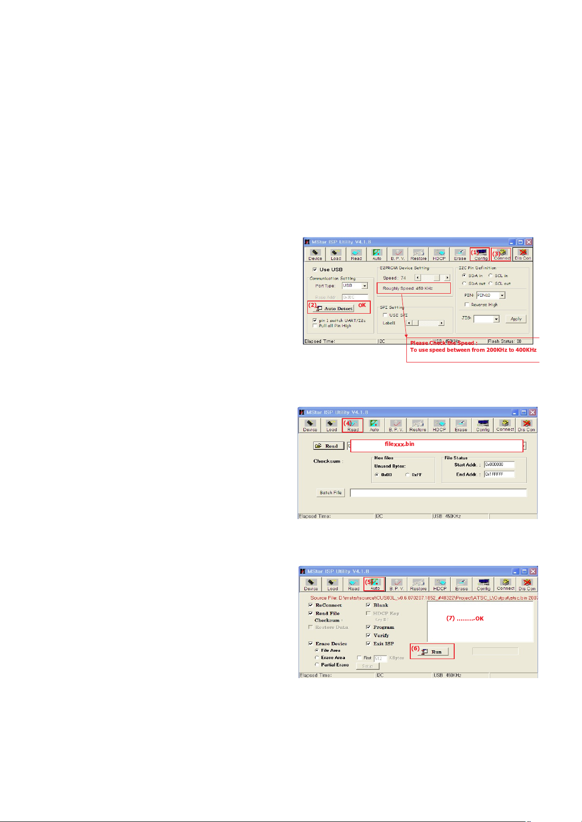
(1) Execute ISP program “Mstar ISP Utility” and then click
“Config” tab.
(2) Set as below, and then click “Auto Detect” and check “OK”
message
If display “Error”, Check connect computer, jig, and set.
(3) Click “Connect” tab. If display “Can’t ”, Check connect
computer, jig, and set.
(4) Click “Read” tab, and then load download file(XXXX.bin)
by clicking “Read”
(5) Click “Auto” tab and set as below
(6) Click “Run”.
(7) After downloading, check “OK” message.
(1)
(3)
(2) OK
Please Check the Speed :
To use speed between from 200KHz to 400KHz
(4)
filexxx.bin
(5)
(6)
(7) ÉÉÉ.OK
Page 10
4. ADC Process
4-1. Auto ADC Process (using DFT)
PC (for communication through RS-232C) UART Baud rate
: 115200 bps
Command : aa 00 00 (Start factory mode)
Command : ad 00 10 (working Auto ADC)
Command : aa 00 90 (End of Auto ADC Process)
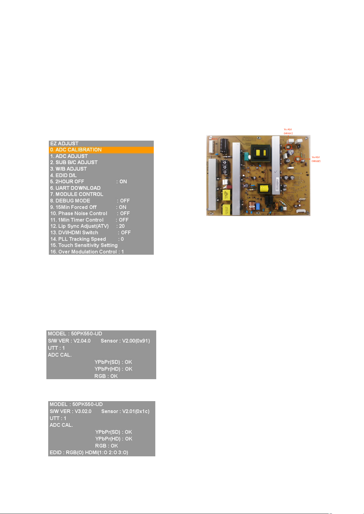
4-2. Manual ADC Process using Service
Remocon
After enter Service Mode by pushing “ADJ” key, execute
“ADC Adjust” by pushing “G” key at “0. ADC CALIBRATION”.
4-3. Confirmation
(1) We confirm whether “0xBF(480i)/0xC8(1080i)” address of
EEPROM “0xA2” is “0xAA” or not.
(2) If “0xBF(480i)/0xC8(1080i)” address of EEPROM “0xA2”
isn’t “0xAA”, we adjust once more
(3) We can confirm the ADC values from “0xB9 ~ 0xBE(480i) /
0xC2 ~ (1080i)” addresses in a page “0xA2”
* Manual ADC Confirmation using Service Remocon. After
enter Service Mode by pushing “INSTART” key,
5. DDC EDID Write Confirmation
6. Total Assembly line process
* Caution : Each PCB assembly must be checked by check JIG
set.(Because power PCB Assembly damages to PDP Module,
especially be careful)
* Caution: Set up “RF mode(noise)” before voltage adjustment.
6-1. POWER PCB Ass’y Voltage
adjustment (Va, Vs voltage adjustment)
(1) Test equipment : D.M.M 1EA
(2) Connection Diagram for Measuring : refer to fig.1
(fig.1 : Power PCB Assy Voltage adjustment)
6-2. Adjustment method
(1) Vs adjustment (refer fig.1)
1) Connect + terminal of D.M.M. to Vs pin of
P812(42”:P811), connect -terminal to GND pin of
P812(42”:P811)
2) After turning VR901, voltage of D.M.M adjustment as
same as Vs voltage which on label of panel left/top (
deviation ; ±0.5V)
(2) Va adjustment (refer fig.1)
1) After receiving 100% Full White Pattern, HEAT RUN.
2) Connect + terminal of D.M.M. to Va pin of
P812(42”:P811), connect -terminal to GND pin of
P811(42”:P812).
3) After turning VR502,voltage of D.M.M adjustment as
same as Va voltage which on label of panel left/top
(deviation; ±0.5V)
- 10 -
LGE Internal Use OnlyCopyright ©2010 LG Electronics Inc. All rights reserved.
Only for training and service purposes
<XPOWER4 42T1 PSU>
Page 11
7. DDC EDID Write
MODEL NAME: LG TV (Not necessary)
Caution: Please only check write status in Instart-menu
7-1. Manual Download(using DFT)
PC(for communication through RS-232C), UART baud rate:
115200 bps
Command : aa 00 00 (Start Factory mode)
Command : ae 00 10 (Download All EDID)
Command : aa 00 90 (End of Factory mode)
7-2. Manual EDID D/L using Service Remocon
(1) After enter Service Mode by pushing “ADJ” key, select “4.
EDID D/L”.
(2) Finally execute “START” by pushing “
G” or “9”key.
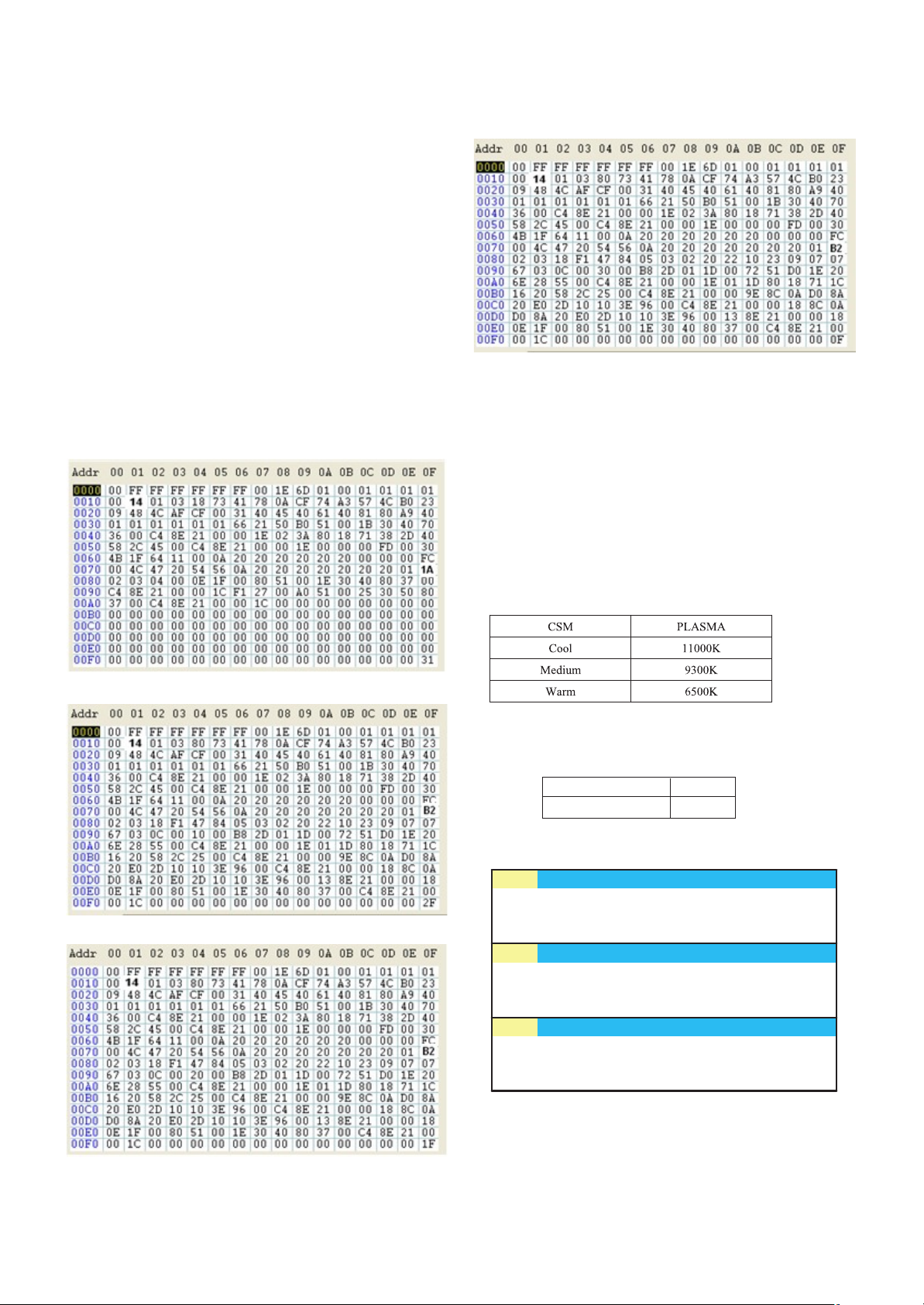
7-3 HD EDID DATA
RGB EDID DATA
HDMI-1 EDID DATA
HDMI-2 EDID DATA
HDMI-3 EDID DATA
8. Adjustment of White Balance
Caution: Press the POWER ON KEY on R/C before W/B adjustment.
8-1. Test Equipment
- Color Analyzer(CS-1000, CA-100+(CH.10), CA-210(CH.10) )
[ Please adjust CA-100+ / CA-210 by CS-1000 before measuring
--> You should use Channel 10 which is Matrix compensated
(White, Red, Green, Blue revised) by CS-1000 and adjust
in accordance with White balance adjustment coordinate.
O Color temperature standards according to CSM and Module
O Change target luminance and range of the Auto adjustment
W/B equipment.
O White balance adjustment coordinate and color temperature
- 11 -
LGE Internal Use OnlyCopyright ©2010 LG Electronics Inc. All rights reserved.
Only for training and service purposes
0.0030.0030.003
[ PC (for communication through RS-232C) ==> UART Baud rate : 115200 bps
3uv
0.329±0.0020.329±0.0020.329y
0.313±0.0020.313±0.0020.313x
CA-210 (CH.10)CA-100+ (CH.10)CS-1000Warm
0.0000.0000.0003uv
0.293±0.0020.293±0.0020.293y
0.285±0.0020.285±0.0020.285x
CA-210 (CH.10)CA-100+ (CH.10)CS-1000
Medium
0.0000.0000.0003uv
0.283±0.0020.283±0.0020.283y
0.276±0.0020.276±0.0020.276x
CA-210 (CH.10)CA-100+ (CH.10)CS-1000Cool
Target luminance 65
Range 20
Page 12
- 12 -
LGE Internal Use OnlyCopyright ©2010 LG Electronics Inc. All rights reserved.
Only for training and service purposes
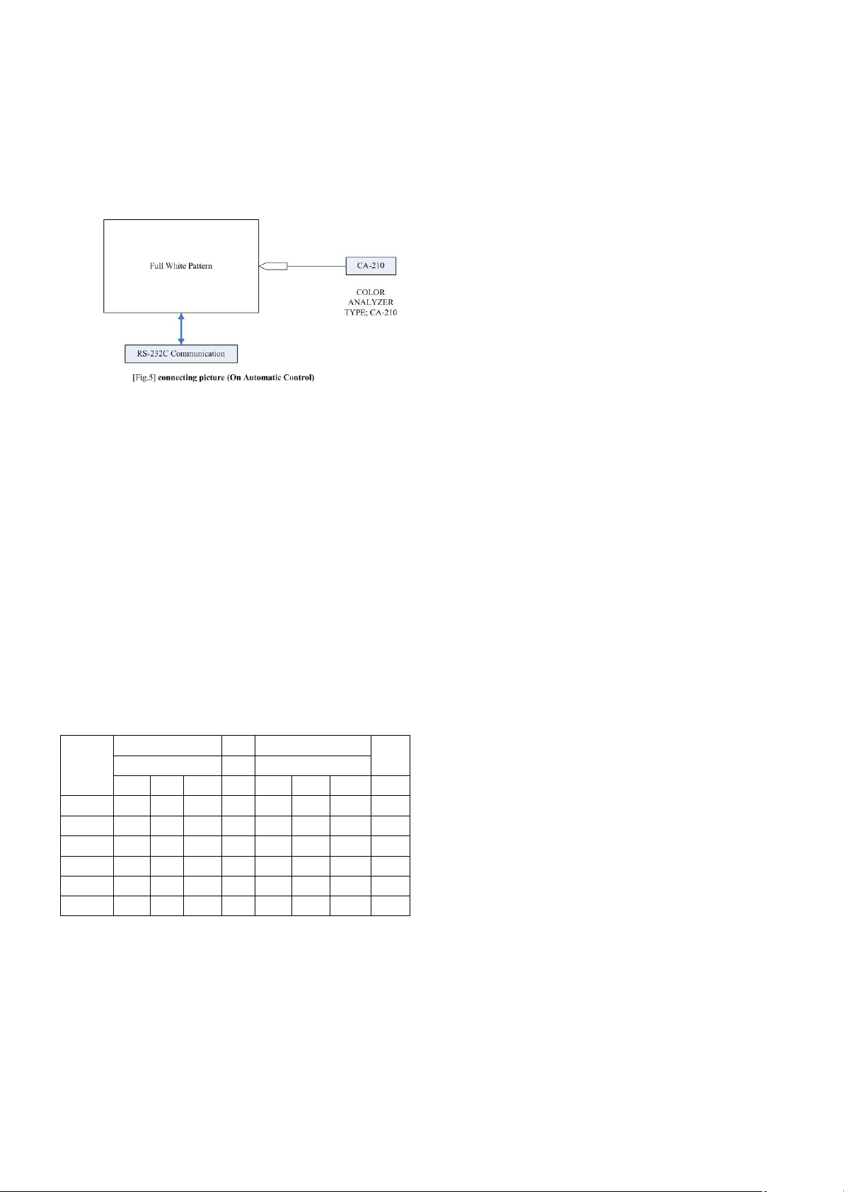
8-2. Connecting Picture of the Measuring
Instrument (On Automatic control )
Inside PATTERN is used when W/B is controlled. Connect to
auto controller or push control R/C ADJ Key‡ Enter the mode
of White-Balance, the pattern will come out.
8-3. Auto-control interface and directions
(1) Adjust in the place where the influx of light like floodlight
around is blocked. (illumination is less than 10ux).
(2) In case of PDP: Measure and adjust after sticking the
Color Analyzer (CA-100+, CA210 ) to the side of the
module.
In case of LCD: Adhere closely the Color Analyzer
(CA210) to the module less than 10cm distance, keep it
with the surface of the Module and Color Analyzer’s Prove
vertically.(80~100°).
(3) Aging time
1) After aging start, keep the power on (no suspension of
power supply) and heat-run over 5 minutes.
2) In case of PDP, keep white pattern using inside pattern.
3) In case of LCD, using ’no signal’ or ‘full white pattern’ or
the others, check the back light on.
O Auto adjustment Map(RS-232C)
8-4. Manual white Balance
(1) Press the POWER ON KEY on R/C for adjustment and
heat run over 5 minutes.
(2) Zero Calibrate CA-100+ / CA-210, and when controlling,
stick the sensor to the center of PDP module surface.
(3) Press the ADJ KEY on R/C and enter EZ ASJUST
Select “3.W/B ADJUST” and press ENTER(V)
Set test-pattern on and display inside pattern.
(4) Control is carried out on three color temperatures, COOL,
MEDIUM, WARM.(Control is carried out three times)
< Temperature: COOL >
- R-offset / G-offset / B-offset is set to 128
- Control R-Gain and G-Gain.
- Each gain is limited to 192
< Temperature: MEDIUM >
- R-offset / G-offset / B-offset is set to 128
- Control R-Gain and G-Gain.
- Each gain is limited to 192
< Temperature: WARM >
- R-offset / G-offset / B-offset is set to 128
- Control G-Gain and B-Gain.
- Each gain is limited to 192
9. HDCP SETTING(Not necessary)
Caution: Key is saved in external eeprom.
10. RS-232C
Press In-start key and select 4.Baud Rate menu. Check RS232C after changing Baud Rate 115200.
RS-232C COMMAND
CENTER
[CMD ID DATA] MIN (DEFAULT) MAX
Cool Mid Warm Cool Mid Warm
R Gain jg Ja jd 00 192 192 192 255
G Gain jh Jb je 00 192 192 192 255
B Gain ji Jc jf 00 192 192 192 255
R Cut 128 128 128 255
G Cut 128 128 128 255
B Cut 128 128 128 255
Page 13
11. TOOL OPTION
11-1. Using DFT(Auto)
PC (for communication through RS-232C) UART Baud rate :
115200 bps
Command : ab 00 00 DATA(Model Number(hexadecimal))
11-2. Setting Manual
Press ADJ R/C In-start key and select 0.TOOL OPTION,
Select Model Number by using R/C number(0~9) key or select
Model Number by using
F/G(VOL +/-) in accordance with
destination.
Finally press
9 (enter) key.
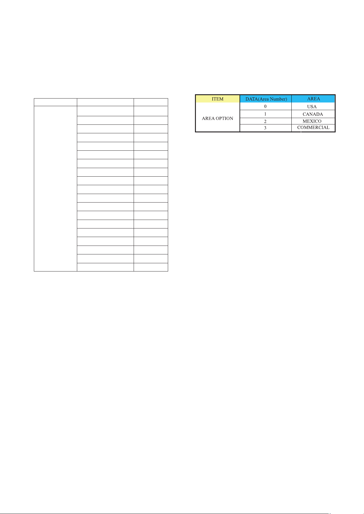
12. AREA OPTION
12-1. Using DFT(Auto)
PC (for communication through RS-232C) ==> UART Baud
rate : 115200 bps
Command : ah 00 00 DATA(Area Number(hexadecimal))
12-2. Setting Manual
Press ADJ R/C In-start key and select 1.AREA OPTION,
Select Model Number by using
F/G(VOL +/-) in accordance
with destination
- 13 -
LGE Internal Use OnlyCopyright ©2010 LG Electronics Inc. All rights reserved.
Only for training and service purposes
ITEM DATA(Model Number) M
TOOL OPTION 0 42PJ350
1 50PJ350
2 42PJ360
3 50PJ360
4 42PJ550
5 50PJ550
6 50PK360
7 50PK550
8 60PK550
10 42PJ250
11 50PJ250
12 42PJ340
13 50PJ340
14 50PK250
15 60PK250
16 60PK280
17 50PK350
18 50PK540
19 60PK540
Page 14
- 14 -
LGE Internal Use OnlyCopyright ©2010 LG Electronics Inc. All rights reserved.
Only for training and service purposes
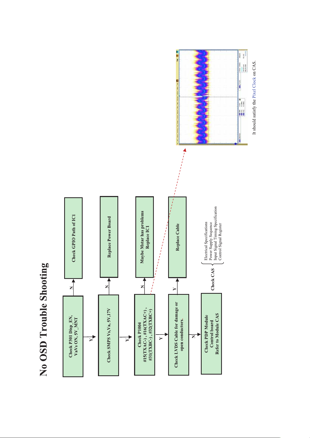
TROUBLE SHOOTING GUIDE
Page 15
- 15 -
LGE Internal Use OnlyCopyright ©2010 LG Electronics Inc. All rights reserved.
Only for training and service purposes
Page 16
- 16 -
LGE Internal Use OnlyCopyright ©2010 LG Electronics Inc. All rights reserved.
Only for training and service purposes
Page 17
- 17 -
LGE Internal Use OnlyCopyright ©2010 LG Electronics Inc. All rights reserved.
Only for training and service purposes
Page 18

- 18 -
LGE Internal Use OnlyCopyright ©2010 LG Electronics Inc. All rights reserved.
Only for training and service purposes
Page 19

- 19 -
LGE Internal Use OnlyCopyright ©2010 LG Electronics Inc. All rights reserved.
Only for training and service purposes
Page 20

- 20 -
LGE Internal Use OnlyCopyright ©2010 LG Electronics Inc. All rights reserved.
Only for training and service purposes
Page 21

- 21 -
LGE Internal Use OnlyCopyright ©2010 LG Electronics Inc. All rights reserved.
Only for training and service purposes
Page 22

- 22 -
LGE Internal Use OnlyCopyright ©2010 LG Electronics Inc. All rights reserved.
Only for training and service purposes
Page 23

- 23 -
LGE Internal Use OnlyCopyright ©2010 LG Electronics Inc. All rights reserved.
Only for training and service purposes
Page 24

- 24 -
LGE Internal Use OnlyCopyright ©2010 LG Electronics Inc. All rights reserved.
Only for training and service purposes
Page 25

- 25 -
LGE Internal Use OnlyCopyright ©2010 LG Electronics Inc. All rights reserved.
Only for training and service purposes
Page 26

- 26 -
LGE Internal Use OnlyCopyright ©2010 LG Electronics Inc. All rights reserved.
Only for training and service purposes
Page 27

- 27 -
LGE Internal Use OnlyCopyright ©2010 LG Electronics Inc. All rights reserved.
Only for training and service purposes
Page 28

- 28 -
LGE Internal Use OnlyCopyright ©2010 LG Electronics Inc. All rights reserved.
Only for training and service purposes
Page 29

- 29 -
LGE Internal Use OnlyCopyright ©2010 LG Electronics Inc. All rights reserved.
Only for training and service purposes
Page 30

- 30 -
LGE Internal Use OnlyCopyright ©2010 LG Electronics Inc. All rights reserved.
Only for training and service purposes
Page 31

- 31 -
LGE Internal Use OnlyCopyright ©2010 LG Electronics Inc. All rights reserved.
Only for training and service purposes
Page 32

- 32 -
LGE Internal Use OnlyCopyright ©2010 LG Electronics Inc. All rights reserved.
Only for training and service purposes
Page 33

- 33 -
LGE Internal Use OnlyCopyright ©2010 LG Electronics Inc. All rights reserved.
Only for training and service purposes
Page 34

- 34 -
LGE Internal Use OnlyCopyright ©2010 LG Electronics Inc. All rights reserved.
Only for training and service purposes
Page 35

- 35 -
LGE Internal Use OnlyCopyright ©2010 LG Electronics Inc. All rights reserved.
Only for training and service purposes
Page 36

- 36 -
LGE Internal Use OnlyCopyright ©2010 LG Electronics Inc. All rights reserved.
Only for training and service purposes
Page 37

- 37 -
LGE Internal Use OnlyCopyright ©2010 LG Electronics Inc. All rights reserved.
Only for training and service purposes
Page 38

- 38 -
LGE Internal Use OnlyCopyright ©2010 LG Electronics Inc. All rights reserved.
Only for training and service purposes
Page 39

- 39 -
LGE Internal Use OnlyCopyright ©2010 LG Electronics Inc. All rights reserved.
Only for training and service purposes
Page 40

- 40 -
LGE Internal Use OnlyCopyright ©2010 LG Electronics Inc. All rights reserved.
Only for training and service purposes
Page 41

- 41 -
LGE Internal Use OnlyCopyright ©2010 LG Electronics Inc. All rights reserved.
Only for training and service purposes
Page 42

- 42 -
LGE Internal Use OnlyCopyright ©2010 LG Electronics Inc. All rights reserved.
Only for training and service purposes
Page 43

- 43 -
LGE Internal Use OnlyCopyright ©2010 LG Electronics Inc. All rights reserved.
Only for training and service purposes
Page 44

- 44 -
LGE Internal Use OnlyCopyright ©2010 LG Electronics Inc. All rights reserved.
Only for training and service purposes
Page 45

- 45 -
LGE Internal Use OnlyCopyright ©2010 LG Electronics Inc. All rights reserved.
Only for training and service purposes
Page 46

- 46 -
LGE Internal Use OnlyCopyright ©2010 LG Electronics Inc. All rights reserved.
Only for training and service purposes
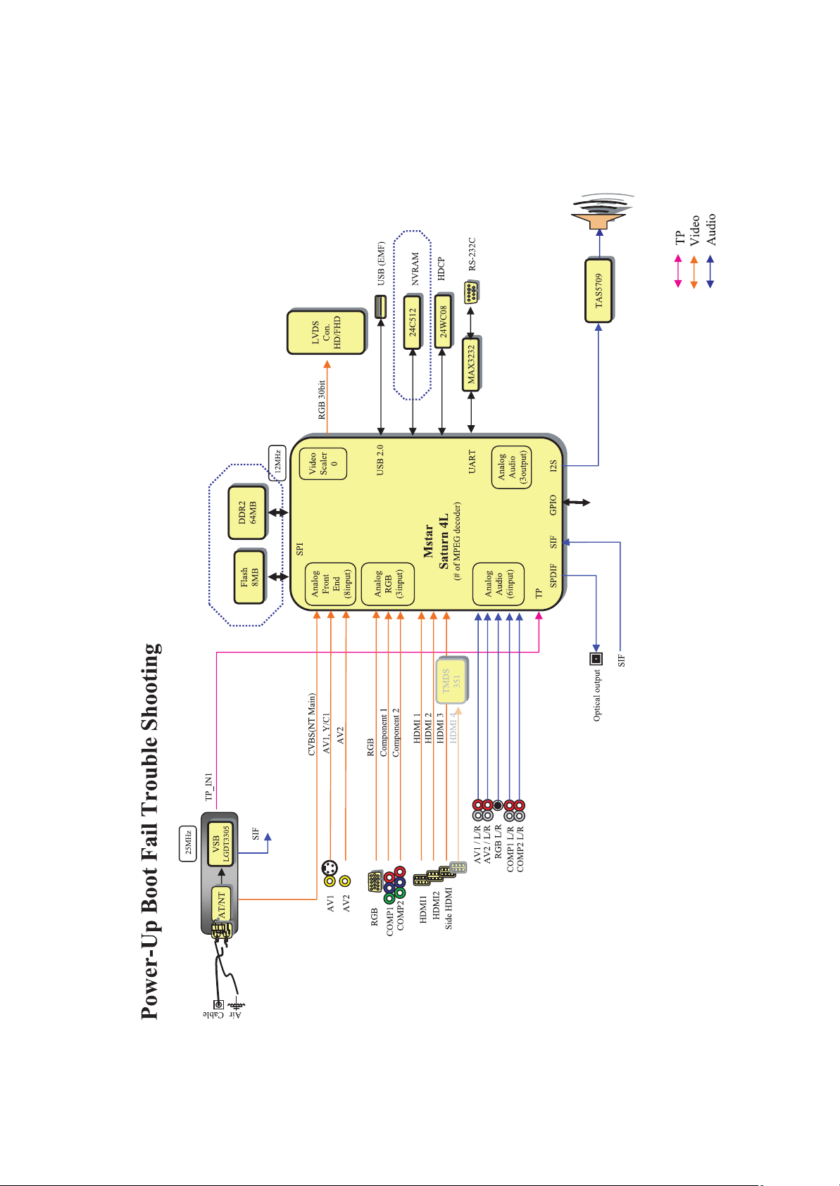
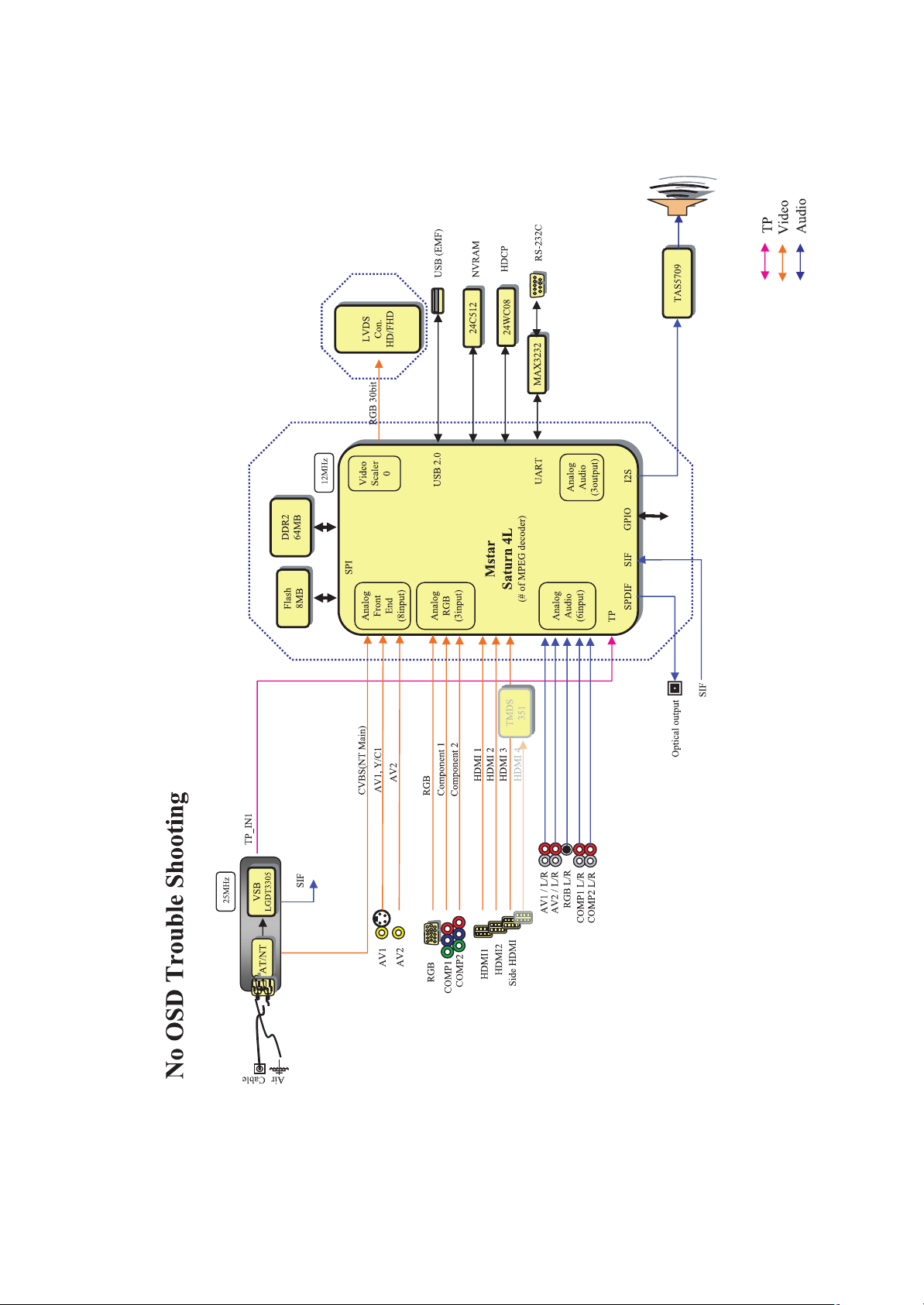
BLOCK DIAGRAM
ATI
X260
ATI
X260
TAS5709
TAS5709
DDR2
64/128MB
DDR2
64/128MB
RGB 30bit
USB 1
USB (EMF)
24C512
24C512
VSB
LGDT3305
VSB
LGDT3305
LVDS
Con.
HD/FHD
LVDS
Con.
HD/FHD
SIF
Flash
8MB
Flash
8MB
12MHz
25MHz
MAX3232
MAX3232
IR Path through
MIC2019
MIC2019
USB 2
USB (SVC)
31.875MHz
NL17SZ
NL17SZ
Analog
RGB
(3 input)
Analog
Front
End
(8 input)
SPI
Analog
Audio
(6 input)
Analog
Audio
(3 output)
Video
Sccaler
0
RS-232C
유선
IR
CVBS(NT Main)
AV 1
AV 2
RGB
COMP 1
COMP 2
HDMI 1
HDMI 2
Side HDMI
AV 1 / L/R
AV 2 / L/R
RGB L/R
COMP1 L/R
COMP2 L/R
Mstar
Saturn 4L
(# of MPEG decoder)
12C Port0
UART
GPIO
IR
12S
XC5001
SIF
TP_IN1
TP
Video
Audio
Page 47

400
EXPLODED VIEW
Many electrical and mechanical parts in this chassis have special safety-related characteristics. These
parts are identified by in the Schematic Diagram and EXPLODED VIEW.
It is ess ential th at these sp ecial saf ety part s s hould be re placed wi th the same co mponen ts as
recommended in this manual to prevent X-RADIATION, Shock, Fire, or other Hazards.
Do not modify the original design without permission of manufacturer.
IMPORTANT SAFETY NOTICE
300
305
200
240
302
205
301
206
602
601
202
207
580
303
604
304
520
204
590
501
201
203
570
900
A12
120
A9
A10
LV1
- 47 -
A2
LGE Internal Use Only
Page 48

Copyright © 2010 LG Electronics Inc. All rights reserved.
Only for training and service purposes
LGE Internal Use Only
Page 49

Copyright © 2010 LG Electronics Inc. All rights reserved.
Only for training and service purposes
LGE Internal Use Only
Page 50

Copyright © 2010 LG Electronics Inc. All rights reserved.
Only for training and service purposes
LGE Internal Use Only
Page 51

Copyright © 2010 LG Electronics Inc. All rights reserved.
Only for training and service purposes
LGE Internal Use Only
Page 52

Copyright © 2010 LG Electronics Inc. All rights reserved.
Only for training and service purposes
LGE Internal Use Only
Page 53

Copyright © 2010 LG Electronics Inc. All rights reserved.
Only for training and service purposes
LGE Internal Use Only
Page 54

Copyright © 2010 LG Electronics Inc. All rights reserved.
Only for training and service purposes
LGE Internal Use Only
Page 55

Copyright © 2010 LG Electronics Inc. All rights reserved.
Only for training and service purposes
LGE Internal Use Only
Page 56

 Loading...