

Page 1

Please read this manual carefully before operating
your set.
Retain it for future reference.
Record model number and serial number of the set.
See the label attached on the back cover and quote
this information to your dealer
when you require service.
LCD TV PLASMA TV
OWNER’S MANUAL
LCD TV MODELS
32LG60UR
32LG70UR
42LG60FR
47LG60FR
PLASMA TV MODELS
42PG60UR
50PG60UR
50PG70FR
60PG70FR
P/NO : MFL41469209 (0807-REV06)
www.lge.com
MFL41469209-Edit1-en 7/29/08 3:52 PM Page 1
Page 2

MFL41469209-Edit1-en 7/29/08 3:52 PM Page 2
Page 3
1
The lightning flash with arrowhead symbol, within an equilateral triangle,
is intended to alert the user to the presence of uninsulated “dangerous voltage” within the product’s enclosure that may be of sufficient magnitude to
constitute a risk of electric shock to persons.
The exclamation point within an equilateral triangle is intended to alert the
user to the presence of important operating and maintenance (servicing)
instructions in the literature accompanying the appliance.
TO REDUCE THE RISK OF ELECTRIC SHOCK DO NOT REMOVE COVER (OR
BACK). NO USER SERVICEABLE PARTS INSIDE. REFER TO QUALIFIED SERVICE
PERSONNEL.
WARNING/CAUTION
TO REDUCE THE RISK OF FIRE AND ELECTRIC SHOCK, DO NOT EXPOSE THIS
PRODUCT TO RAIN OR MOISTURE.
MFL41469209-Edit1-en 7/29/08 3:52 PM Page 1
Page 4
2
SAFETY INSTRUCTIONS
IMPORTANT SAFETY INSTRUCTIONS
Important safety instructions shall be provided with each apparatus. This information shall be given in a separate
booklet or sheet, or be located before any operating instructions in an instruction for installation for use and
supplied with the apparatus.
This information shall be given in a language acceptable to the country where the apparatus is intended to be used.
The important safety instructions shall be entitled “Important Safety Instructions”. The following safety
instructions shall be included where applicable, and, when used, shall be verbatim as follows. Additional safety
information may be included by adding statements after the end of the following safety instruction list. At the
manufacturer’s option, a picture or drawing that illustrates the intent of a specific safety instruction may be
placed immediately adjacent to that safety instruction:
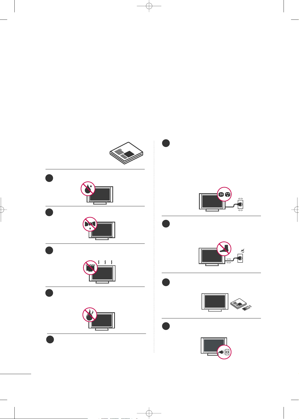
Read these instructions.
Keep these instructions.
Heed all warnings.
Follow all instructions.
Do not use this apparatus near water.
Clean only with dry cloth.
Do not block any ventilation openings. Install in
accordance with the manufacturer’s instructions.
Do not install near any heat sources such as
radiators, heat registers, stoves, or other apparatus
(including amplifiers)that produce heat.
When mounting a TV it on the wall, make sure
not to install TV by the hanging power and signal cables on the back of the TV.
Do not defeat the safety purpose of the polarized
or grounding-type plug. A polarized plug has
two blades with one wider than the other. A
grounding type plug has two blades and a third
grounding prong, The wide blade or the third
prong are provided for your safety. If the provided
plug does not fit into your outlet, consult an
electrician for replacement of the obsolete outlet.
Protect the power cord from being walked on
or pinched particularly at plugs, convenience
receptacles, and the point where they exit from
the apparatus.
Only use attachments/accessories specified by
the manufacturer.
Unplug this apparatus during lightning storms
or when unused for long periods of time.
1
2
3
4
6
7
8
9
5
MFL41469209-Edit1-en 7/29/08 3:52 PM Page 2
Page 5
3
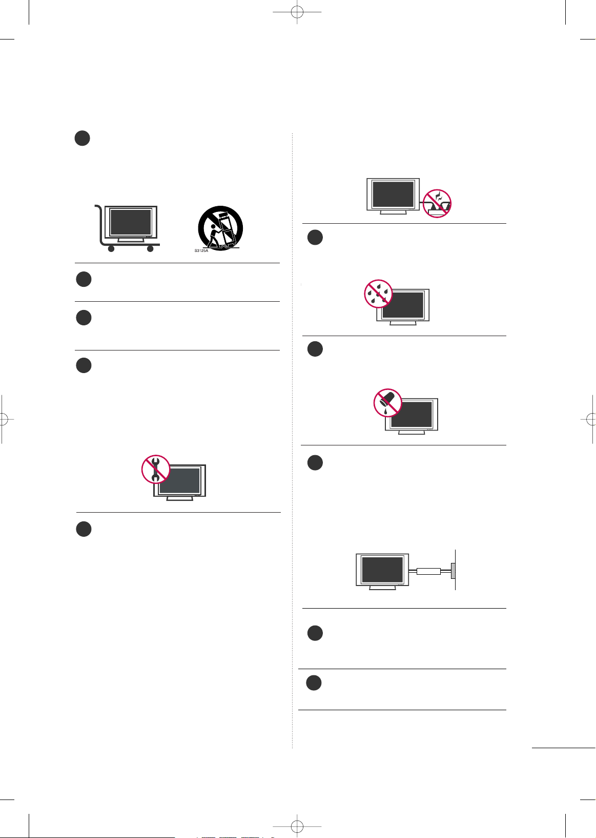
Use only with the cart, stand, tripod, bracket,
or table specified by the manufacturer, or sold
with the apparatus. When a cart is used, use
caution when moving the cart/apparatus
combination to avoid injury from tip-over.
Never touch this apparatus or antenna during
a thunder or lighting storm.
Do not allow a impact shock or any objects to
fall into the product, and do not drop onto the
screen with something.
Refer all servicing to qualified service personnel.
Servicing is required when the apparatus has
been damaged in any way, such as power-supply
cord or plug is damaged, liquid has been spilled
or objects have fallen into the apparatus, the
apparatus has exposed to rain or moisture,
does not operate normally, or has been
dropped.
CAUTION concerning the Power Cord :
Most appliances recommend they be placed
upon a dedicated circuit; that is, a single outlet
circuit which powers only that appliance and
has no additional outlets or branch circuits.
Check the specification page of this owner's
manual to be certain.
Do not overload wall outlets. Overloaded wall
outlets, loose or damaged wall outlets, extension
cords, frayed power cords, or damaged or
cracked wire insulation are dangerous. Any of
these conditions could result in electric shock
or fire. Periodically examine the cord of your
appliance, and if its appearance indicates damage or deterioration, unplug it, discontinue use
of the appliance, and have the cord replaced
with an exact replacement part by an authorized
servicer. Protect the power cord from physical
or mechanical abuse, such as being twisted,
kinked, pinched, closed in a door, or walked
upon. Pay particular attention to plugs, wall
outlets, and the point where the cord exits the
appliance.
Outdoor use marking :
WARNING - To reduce the risk of fire or elec-
tric shock, do not expose this appliance to rain
or moisture.
Wet Location Marking : Apparatus shall not be
exposed to dripping or splashing and no
objects filled with liquids, such as vases, shall
be placed on or over apparatus.
GGRROOUUNNDD IINNGG
Ensure that you connect the earth ground wire
to prevent possible electric shock. If grounding
methods are not possible, have a qualified
electrician install a separate circuit breaker.
Do not try to ground the unit by connecting it
to telephone wires, lightening rods, or gas pipes.
DDIISSCCOONNNNEECCTTIINNGG DDEEVVIICCEE FFRROOMM MMAAIINNSS
Mains plug is the disconnecting device. The
plug must remain readily operable.
Keep the product away from direct sunlight.
- The product can be damaged.
10
13
11
12
14
15
16
17
18
Power
Supply
Short-circuit
Breaker
19
MFL41469209-Edit1-en 7/29/08 3:52 PM Page 3
Page 6

4
CONTENTS
WARNING/CAUTION
. . . . . . . . . . . . . . . . . . . . . . . . . . . . . . . 1
SAFETY INSTRUCTIONS
. . . . . . . . . . . . . . . . . . . . . . . . . . 2
PREPARATION
Accessories
. . . . . . . . . . . . . . . . . . . . . . . . . . . . . . . . . . . . . . . . . . . . . . . . . . . . . . 7
Front Panel Information
. . . . . . . . . . . . . . . . . . . . . . . . . . . . . . . . . . . . . 8
Back Panel Information . . . . . . . . . . . . . . . . . . . . . . . . . . . . . . . . . . . . 10
Stand Installation
. . . . . . . . . . . . . . . . . . . . . . . . . . . . . . . . . . . . . . . . . . . . 13
Cable Management
. . . . . . . . . . . . . . . . . . . . . . . . . . . . . . . . . . . . . . . . . 15
Securing the TV to the wall fall over.
. . . . . . . . . . . . . . . . . 18
Protection Cover
. . . . . . . . . . . . . . . . . . . . . . . . . . . . . . . . . . . . . . . . . . . . . 19
Swivel Stand
. . . . . . . . . . . . . . . . . . . . . . . . . . . . . . . . . . . . . . . . . . . . . . . . . . . . 19
Desktop Pedestal Installation
. . . . . . . . . . . . . . . . . . . . . . . . . . . 20
Wall Mount: Horizontal Installation
. . . . . . . . . . . . . . . . . . . 20
Attaching The TV To a Desk
. . . . . . . . . . . . . . . . . . . . . . . . . . . . 20
Antenna Connection
. . . . . . . . . . . . . . . . . . . . . . . . . . . . . . . . . . . . . . . . 21
EXTERNAL EQUIPMENT SETUP
HD Receiver Setup
. . . . . . . . . . . . . . . . . . . . . . . . . . . . . . . . . . . . . . . . .
22
DVD Setup
. . . . . . . . . . . . . . . . . . . . . . . . . . . . . . . . . . . . . . . . . . . . . . . . . . . . . 25
VCR Setup
. . . . . . . . . . . . . . . . . . . . . . . . . . . . . . . . . . . . . . . . . . . . . . . . . . . . . 28
Other A/V Source Setup
. . . . . . . . . . . . . . . . . . . . . . . . . . . . . . . . . 31
PC Setup
. . . . . . . . . . . . . . . . . . . . . . . . . . . . . . . . . . . . . . . . . . . . . . . . . . . . . . . . 32
USB In Setup . . . . . . . . . . . . . . . . . . . . . . . . . . . . . . . . . . . . . . . . . . . . . . . . . . 38
External Stereo Setup
. . . . . . . . . . . . . . . . . . . . . . . . . . . . . . . . . . . . . . 39
AV Out Setup
. . . . . . . . . . . . . . . . . . . . . . . . . . . . . . . . . . . . . . . . . . . . . . . . . 39
WATCHING TV / CHANNEL CONTROL
Remote Control Key Functions . . . . . . . . . . . . . . . . . . . . . . . . . 40
Turning On TV
. . . . . . . . . . . . . . . . . . . . . . . . . . . . . . . . . . . . . . . . . . . . . . . . 42
Channel Selection . . . . . . . . . . . . . . . . . . . . . . . . . . . . . . . . . . . . . . . . . . . 42
Volume Adjustment
. . . . . . . . . . . . . . . . . . . . . . . . . . . . . . . . . . . . . . . . . 42
Quick Menu
. . . . . . . . . . . . . . . . . . . . . . . . . . . . . . . . . . . . . . . . . . . . . . . . . . . . 43
On-Screen Menus Selection
. . . . . . . . . . . . . . . . . . . . . . . . . . . . 44
Channel Search
. . . . . . . . . . . . . . . . . . . . . . . . . . . . . . . . . . . . . . . . . . . . . . . 45
- Auto Turning
. . . . . . . . . . . . . . . . . . . . . . . . . . . . . . . . . . . . . . . . . . . . 45
- Manual Turning:Adding / Deleting Channels
. . . . 46
Fine Tuning Adjustment . . . . . . . . . . . . . . . . . . . . . . . . . . . . . . . . . . . 47
Booster
. . . . . . . . . . . . . . . . . . . . . . . . . . . . . . . . . . . . . . . . . . . . . . . . . . . . . . . . . . 48
Favorite Channels Setup
. . . . . . . . . . . . . . . . . . . . . . . . . . . . . . . . . . 49
Key Lock . . . . . . . . . . . . . . . . . . . . . . . . . . . . . . . . . . . . . . . . . . . . . . . . . . . . . . . . . 50
AV Mode . . . . . . . . . . . . . . . . . . . . . . . . . . . . . . . . . . . . . . . . . . . . . . . . . . . . . . . . 51
SimpLink
. . . . . . . . . . . . . . . . . . . . . . . . . . . . . . . . . . . . . . . . . . . . . . . . . . . . . . . . . 52
USB
To use the USB device.................................................................................... 54
Photo list
................................................................................................................................. 55
Music list................................................................................................................................. 57
Movie List
............................................................................................................................... 59
Divx Registration Code................................................................................... 60
PICTURE CONTROL
Watching PIP(Picture-In-Picture) . . . . . . . . . . . . . . . . . . . . . . 61
Picture Size (Aspect Ratio) Control
. . . . . . . . . . . . . . . . . . 62
Preset Picture Settings
. . . . . . . . . . . . . . . . . . . . . . . . . . . . . . . . . . . . . 63
- Picture Mode- Preset
. . . . . . . . . . . . . . . . . . . . . . . . . . . . . . . . 63
- Auto Color Tone Control(Warm/Medium/Cool)
. . 64
Manual Picture Adjustment
. . . . . . . . . . . . . . . . . . . . . . . . . . . . . . 65
- Picture Mode- User Mode
. . . . . . . . . . . . . . . . . . . . . . . . . 65
- Color Tone - User Mode
. . . . . . . . . . . . . . . . . . . . . . . . . . . 66
XD - Picture Improvement Technology
. . . . . . . . . . . . . 67
Advanced - Gamma
. . . . . . . . . . . . . . . . . . . . . . . . . . . . . . . . . . . . . . . . . 69
Advanced - Film Mode
. . . . . . . . . . . . . . . . . . . . . . . . . . . . . . . . . . . . . 70
Advanced - Black (Darkness) Level
. . . . . . . . . . . . . . . . . . . 71
Advanced - Eye Care
. . . . . . . . . . . . . . . . . . . . . . . . . . . . . . . . . . . . . . . 72
Picture Reset
. . . . . . . . . . . . . . . . . . . . . . . . . . . . . . . . . . . . . . . . . . . . . . . . . 73
Power Indicator
. . . . . . . . . . . . . . . . . . . . . . . . . . . . . . . . . . . . . . . . . . . . . . 74
Image Sticking Minimization (ISM) Method
. . . . . . . 75
Power Saving Picture Mode
. . . . . . . . . . . . . . . . . . . . . . . . . . . . . . 76
Factory Reset
. . . . . . . . . . . . . . . . . . . . . . . . . . . . . . . . . . . . . . . . . . . . . . . . . . 77
MFL41469209-Edit1-en 7/29/08 3:52 PM Page 4
Page 7

5
SOUND & LANGUAGE CONTROL
Auto Volume Leveler . . . . . . . . . . . . . . . . . . . . . . . . . . . . . . . . . . . . . . . . 78
Preset Sound Setting - Sound Mode
. . . . . . . . . . . . . . . . 79
Sound Setting Adjustment - User Mode
. . . . . . . . . . . 80
Balance
. . . . . . . . . . . . . . . . . . . . . . . . . . . . . . . . . . . . . . . . . . . . . . . . . . . . . . . . . . . 81
TV Speakers On/Off Setup
. . . . . . . . . . . . . . . . . . . . . . . . . . . . . . 82
Selecting Audio Out
. . . . . . . . . . . . . . . . . . . . . . . . . . . . . . . . . . . . . . . . 83
On-Screen Menus Language Selection
. . . . . . . . . . . . . . 83
Closed Caption
. . . . . . . . . . . . . . . . . . . . . . . . . . . . . . . . . . . . . . . . . . . . . . . 84
TIME SETTING
Clock Setup . . . . . . . . . . . . . . . . . . . . . . . . . . . . . . . . . . . . . . . . . . . . . . . . . . . 85
Auto On/Off Time Setting . . . . . . . . . . . . . . . . . . . . . . . . . . . . . . 86
Sleep Timer Setting
. . . . . . . . . . . . . . . . . . . . . . . . . . . . . . . . . . . . . . . . . 87
Auto Shut-off Setting
. . . . . . . . . . . . . . . . . . . . . . . . . . . . . . . . . . . . . . . 88
APPENDIX
Troubleshooting
. . . . . . . . . . . . . . . . . . . . . . . . . . . . . . . . . . . . . . . . . . . . . . 89
Maintenance
. . . . . . . . . . . . . . . . . . . . . . . . . . . . . . . . . . . . . . . . . . . . . . . . . . . 90
Product Specifications
. . . . . . . . . . . . . . . . . . . . . . . . . . . . . . . . . . . . .
91
Programming the Remote Control
. . . . . . . . . . . . . . . . . . . 93
IR Codes . . . . . . . . . . . . . . . . . . . . . . . . . . . . . . . . . . . . . . . . . . . . . . . . . . . . . . .95
External Control Through RS-232C
. . . . . . . . . . . . . . . . . .97
MFL41469209-Edit1-en 7/29/08 3:52 PM Page 5
Page 8

6
FOR LCD TV
If the TV feels cold to the touch, there may be a small “flicker” when it is turned on. This is normal, there is nothing wrong with TV.
Some minute dot defects may be visible on the screen, appearing as tiny red, green, or blue spots. However, they
have no adverse effect on the monitor's performance.
Avoid touching the LCD screen or holding your finger(s) against it for long periods of time. Doing so may produce
some temporary distortion effects on the screen.
OOnn DDiissppoossaall ((OOnnllyy,, HHgg..llaa mmpp uusseedd LLCCDD TTVV))
a. The fluorescent lamp used in this product contains a small amount of mercury.
b. Do not dispose of this product with general household waste.
c. Disposal of this product must be carried out in accordance to the regulations of your local authority.
PREPARATION
PREPARATION
Ferrite core can be used to reduce the electromagnetic
wave when connecting the power cord.
The closer the location of the ferrite core to the power
plug, the better it is.
Use of ferrite core
(
This feature is not available for all models.
)
Install the power plug closely.
MFL41469209-Edit1-en 7/29/08 3:52 PM Page 6
Page 9
PREPARATION
7
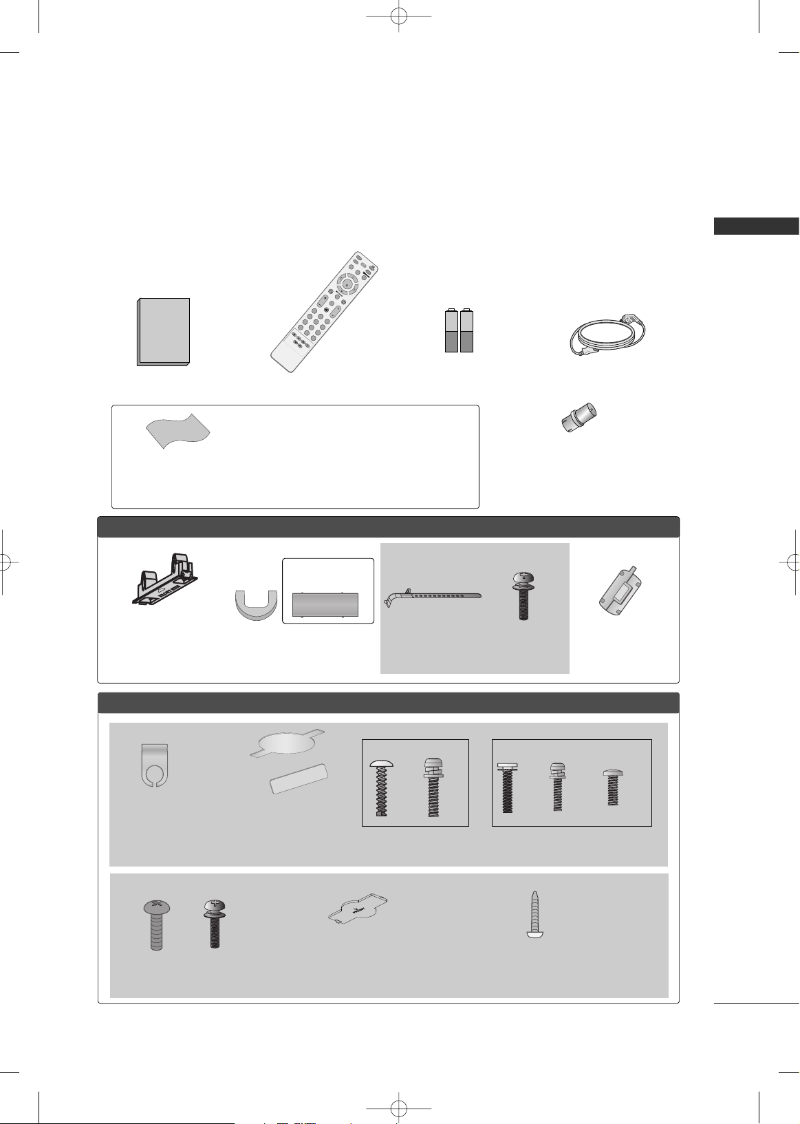
ACCESSORIES
Ensure that the following accessories are included with your TV. If an accessory is missing, please contact the
dealer where you purchased the TV.
The accessories included may differ from the images below.
Owner's Manual
1.5V 1.5V
Owner’s Manual
Batteries
(Some Models)
Power Cord
RF Adapter (Some Models)
You must connect it to the antenna wire after
fixing in Antenna Input.
This adapter is only supplied in Argentina.
* Only wipe spots on the exterior with the polishing cloth.
* Do not wipe roughly when removing stain. Please be cau-
tions of that excessive pressure may cause scratch or discoloration.
Polishing Cloth
(This feature is not available
for all models.)
M
U
T
E
RETURN
A
V
M
O
D
E
F
A
V
T
V
P
O
W
E
R
Q
. M
E
N
U
M
E
N
U
ENTER
V
O
L
C
H
123
456
78
0
9
Q.VIEW
D
V
D
I
N
P
U
T
S
T
B
PIP
Remote Control
FFoorr PPllaassmmaa TTVV mmooddeellss
Cable Management Clip
(Only 50PG60**
,
50/60PG70** )
Protection cover
(Refer to p.19)
(This accessories can be different
from the figures shown here
depending on your models.)
FFoorr LLCCDD TTVV mmooddeellss
(Only 42PG60**)
Cable Holder
Bolts for stand
assembly
(Refer to P.13)
x 4
Cable
Management
Clip
Protection cover
(Refer to p.19)
(This accessories can be
different from the figures shown here
depending on your models.)
Bolts for stand assembly
(Refer to P.14)
(Only 32LG60**)
(Only 42LG60**)
x 3
x 4
x 2
x 4
x 1
3322//4422//4477LLGG 6600
** **
Protection cover
(Refer to p.19)
(This accessories can be different
from the figures shown here depend-
ing on your models.)
Screw for stand fixing
(Refer to P20)
Bolts for stand assembly
(Refer to P.14)
x 4
x 4
3322LL GG7700
** **
or
(This feature is not
available for all models.)
Ferrite Core
MFL41469209-Edit1-en 7/29/08 3:52 PM Page 7
Page 10
PREPARATION
8
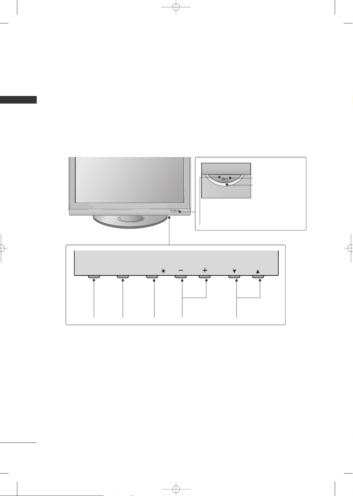
FRONT PANEL INFORMATION
PREPARATION
■
Image shown may differ from your TV.
■
NOTE: If your TV has a protection tape attached, remove the tape.
And then wipe the TV with a cloth (If a polishing cloth is included with your TV, use it).
Plasma TV Models
CHANNEL (
EE, DD
)
Buttons
VOLUME (-,+)
Buttons
MENU
Button
ENTER
Button
INPUT
Button
CH
VOL
MENU
INPUT
ENTER
Remote Control Sensor
POWER Button
Power/Standby Indicator
Illuminates red in standby mode.
Illuminates green when the set is
switched on.
MFL41469209-Edit1-en 7/29/08 3:52 PM Page 8
Page 11
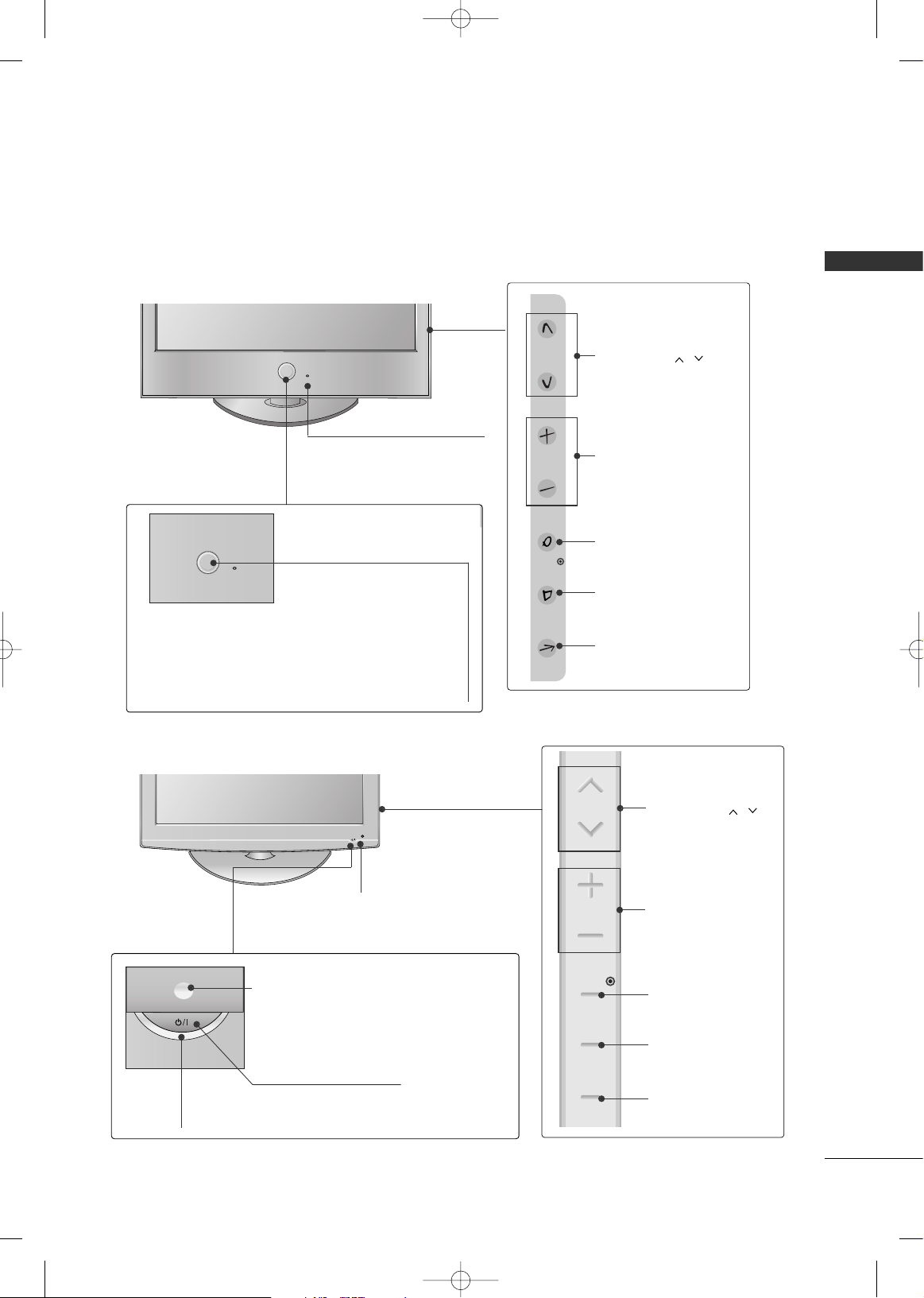
PREPARATION
9
Intelligent Sensor
Adjusts picture according to
the surrounding conditions
CHANNEL ( , )
Buttons
VOLUME (+, -)
Buttons
ENTER Button
MENU Button
INPUT Button
POWER
Remote Control Sensor
Power/Standby Indicator
• Illuminates red in standby mode.
• Illuminates White when the TV is
switched on.
Note: You can adjust
PPoowwee rr
IInnddiiccaatt oorr
in the Option menu.
LCD TV Models
POWER Button
Power/Standby Indicator
Illuminates red in standby mode.
Illuminates blue when the set is switched on.
(Can be adjusted using
PPoowweerr IInnddiiccaattoorr
in
the
Option menu.)
CHANNEL ( , )
Buttons
VOLUME (+, -)
Buttons
ENTER Button
MENU Button
INPUT Button
Intelligent Sensor
Adjusts picture according to the surrounding
conditions
Remote Control Sensor
32/42/47LG60**
32LG70**
MFL41469209-Edit1-en 7/29/08 3:52 PM Page 9
CH
VOL
ENTER
MENU
INPUT
CH
VOL
ENTER
MENU
INPUT
Page 12
PREPARATION
10
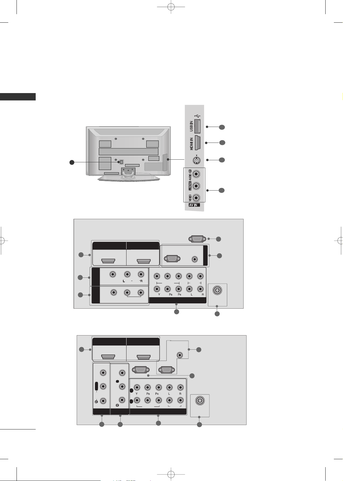
BACK PANEL INFORMATION
PREPARATION
Plasma TV Models
R
■
Here shown may be somewhat different from your TV.
2
S-VIDEO
2
3
2
8
2
1
6
4
3
5
7
10
9
11
1
42/50PG60**
50/60PG70**
COMPONENT IN
AUDIO
(RGB/DVI)
RGB IN (PC)
RS-232C IN
VIDEO
AUDIO
HDMI/DVI IN
ANTENNA
IN
1
2
HDMI IN
VIDEO
AUDIO
AV IN 1
AV OUT
MONO
L /
VARIABLE AUDIO OUT
L
VIDEO
1
2
(CONTROL )
2
1
6
4
5
3
7
MFL41469209-Edit1-en 7/29/08 3:52 PM Page 10
AV
HDMI/DVI IN
1
IN 1
VIDEO
OUT
HDMI IN
2
(
)
AUDIO
MONO
VARIABLE AUDIO OUT
2
1
RGB(PC)
VIDEO
COMPONENT IN
RS-232C IN
(CONTROL )
AUDIO
(RGB/DVI)
AUDIO
RGB IN
ANTENNA
IN
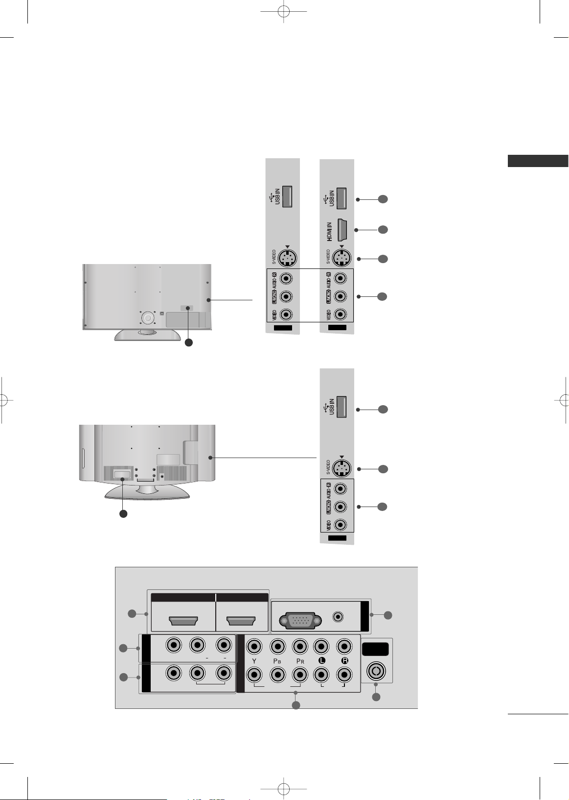
Page 13
PREPARATION
11
LCD TV Models
HDMI IN HDMI/DVI IN
1
1
2
2
AUDIO
RGB
(PC)
RGB IN
COMPONENT IN
AUDIO
VIDEO
(RGB/DVI)
L/L/MONOMONO
R
AUDIOAUDIO
AV
VIDEOVIDEO
IN 1
OUT
VARIABLE AUDIO OUTVARIABLE AUDIO OUT
AV IN 2
ANTENNA
IN
2
1
6
4
3
5
32/42/47LG60**
8
AV IN 2
3
AV IN 2
R
32LG70**
8
11
1
AV IN 2
32LG60
**
9
10
AV IN 2
11
9
10
42/47LG60
**
MFL41469209-Edit1-en 7/29/08 3:52 PM Page 11
Page 14
PREPARATION
12
PREPARATION
HDMI/DVI IN, HDMI IN
Connect a HDMI (DVI) connection to either input.
AV (Audio/Video) IN 1
Connect audio/video output from an external
device to these jacks.
AV OUT
Connect a second TV or monitor.
VARIABLE AUDIO OUT
Connect an external amplifier or add a subwoofer
to your surround sound system.
COMPONENT IN
Connect a component video/audio device to these
jacks.
ANTENNA IN
Connect over-the air signals to this jack.
RGB IN
RGB(PC)
Connect the output from a PC.
AUDIO(RGB/DVI)
Connect the audio from a PC or DTV.
RS-232C IN (CONTROL)(Only Plasma TV models)
For external control devices.
Power Cord Socket
For operation with AC power.
Caution: Never attempt to operate the TV on DC
power.
AV (Audio/Video) IN 2
Connect audio/video output from an external
device to these jacks.
S-VIDEO
Connect S-Video out from an S-VIDEO device.
USB IN
1
2
3
4
5
6
7
8
9
10
11
MFL41469209-Edit1-en 7/29/08 3:52 PM Page 12
Page 15
PREPARATION
13
STAND INSTALLATION
■
Image shown may differ from your TV
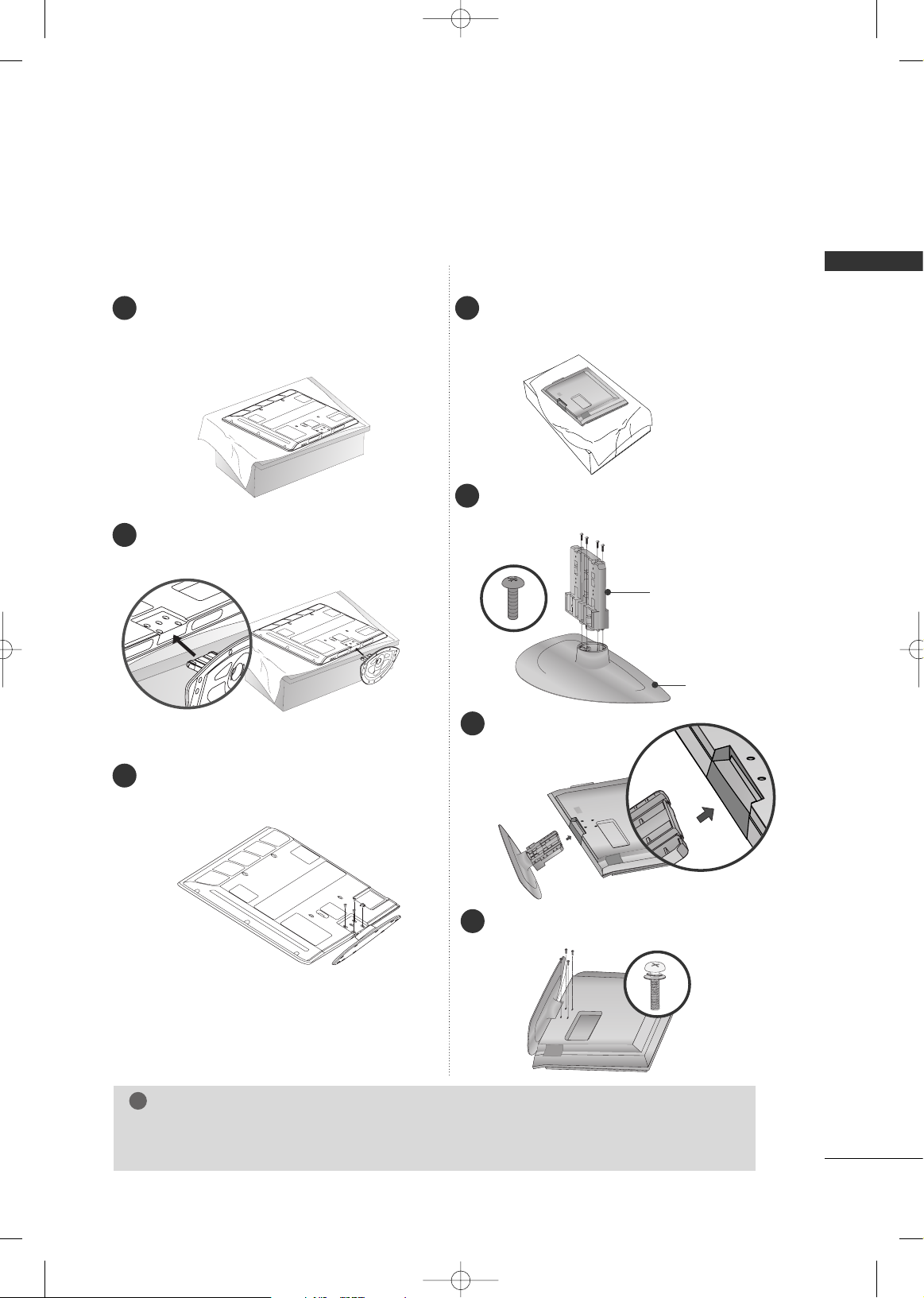
Plasma TV Models
Carefully place the TV screen side down on a
cushioned surface to protect the screen from
damage.
Assemble the TV as shown.
Fix the 4 bolts securely using the holes in the
back of the TV.
1
2
3
Carefully place the TV screen side down on a
cushioned surface to protect the screen from
damage.
Assemble the parts of the
SSttaanndd BBoo ddyy
with
the
CCoo vveerr BBaassee
of the TV.
Assemble the TV as shown.
1
2
3
Fix the 4 bolts securely using the holes in the
back of the TV.
4
SSTTAANN DD BBOO DD YY
CCOOVVEERR BBAASSEE
50/60PG70**
42PG60**
GG
When assembling the desk type stand, check whether the bolt is fully tightened. (If not tightened
fully, the product can tilt forward after the product installation). If you tighten the bolt with excessive
force, the bolt can deviate from abrasion of the tightening part of the bolt.
NOTE
!
MFL41469209-Edit1-en 7/29/08 3:52 PM Page 13
Page 16
PREPARATION
14
PREPARATION
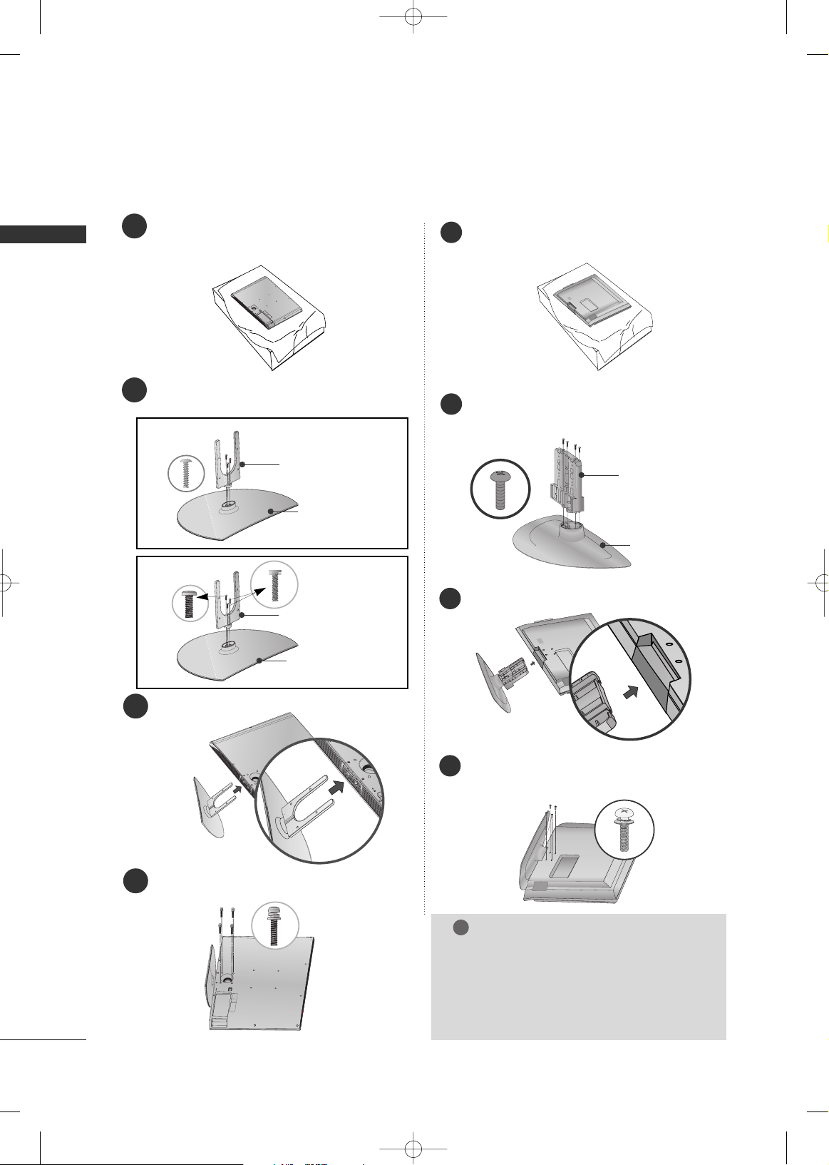
LCD TV Models
1
3
4
Carefully place the TV screen side down on a
cushioned surface to protect the screen from
damage.
2
Assemble the parts of the
SSttaanndd BBoo ddyy
with
the
CCoo vveerr BBaassee
of the TV.
Assemble the TV as shown.
Fix the 4 bolts securely using the holes in the
back of the TV.
SSTTAANN DD BBOO DD YY
CCOOVVEERR BBAASSEE
32LG60
**
SSTTAANN DD BBOO DD YY
42LG60
**
CCOOVVEERR BBAASSEE
32/42LG60** 32LG70**
Assemble the parts of the
SSTTAANN DD BBOODDYY
with
CCOOVVEERR BBAASSEE
of the TV.
2
Assemble the TV as shown.
3
Fix the 4 bolts securely using the holes in the
back of the TV.
4
SSTTAANN DD BBOO DD YY
CCOOVVEERR BBAASSEE
Carefully place the TV screen side down on a
cushioned surface to protect the screen from
damage.
1
GG
When assembling the desk type stand, check
whether the bolt is fully tightened. (If not tightened fully, the product can tilt forward after the
product installation). If you tighten the bolt with
excessive force, the bolt can deviate from abrasion
of the tightening part of the bolt.
NOTE
!
MFL41469209-Edit1-en 7/29/08 3:52 PM Page 14
Page 17
PREPARATION
15
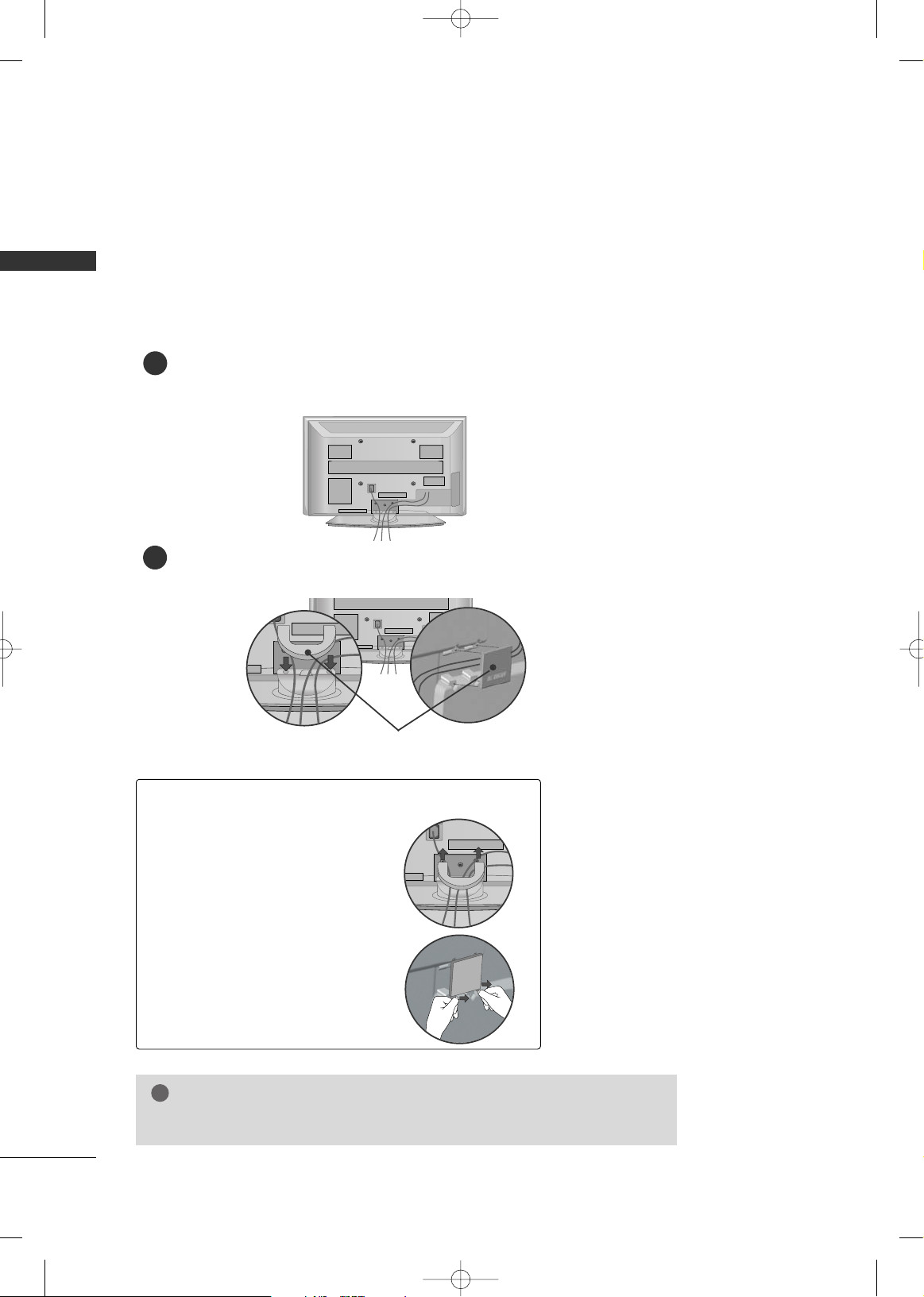
CABLE MANAGEMENT
■
Here shown may be somewhat different from your TV.
Plasma TV Models
42PG60**
Connect the cables as necessary.
To connect additional equipment, see the EXTERNAL EQUIPMENT SETUP section.
1
Install the CABLE MANAGEMENT CLIP as shown.
If your TV has CABLE HOLDER, fix it as shown and bundle the cables.
2
CABLE MANAGEMENT
CLIP
CABLE HOLDER
GG
Do not hold the CABLE MANAGEMENT CLIP when moving the TV.
- If the TV is dropped, you may be injured or the product may be broken.
NOTE
!
How to remove the
CABLE MANAGEMENT CLIP
GG
First, press the cable management. Hold the
CCAABBLLEE MMAANNAAGGEE MMEENNTT
CCLLIIPP
with both hands and pull it upward.
MFL41469209-Edit1-en 7/29/08 3:52 PM Page 15
Page 18
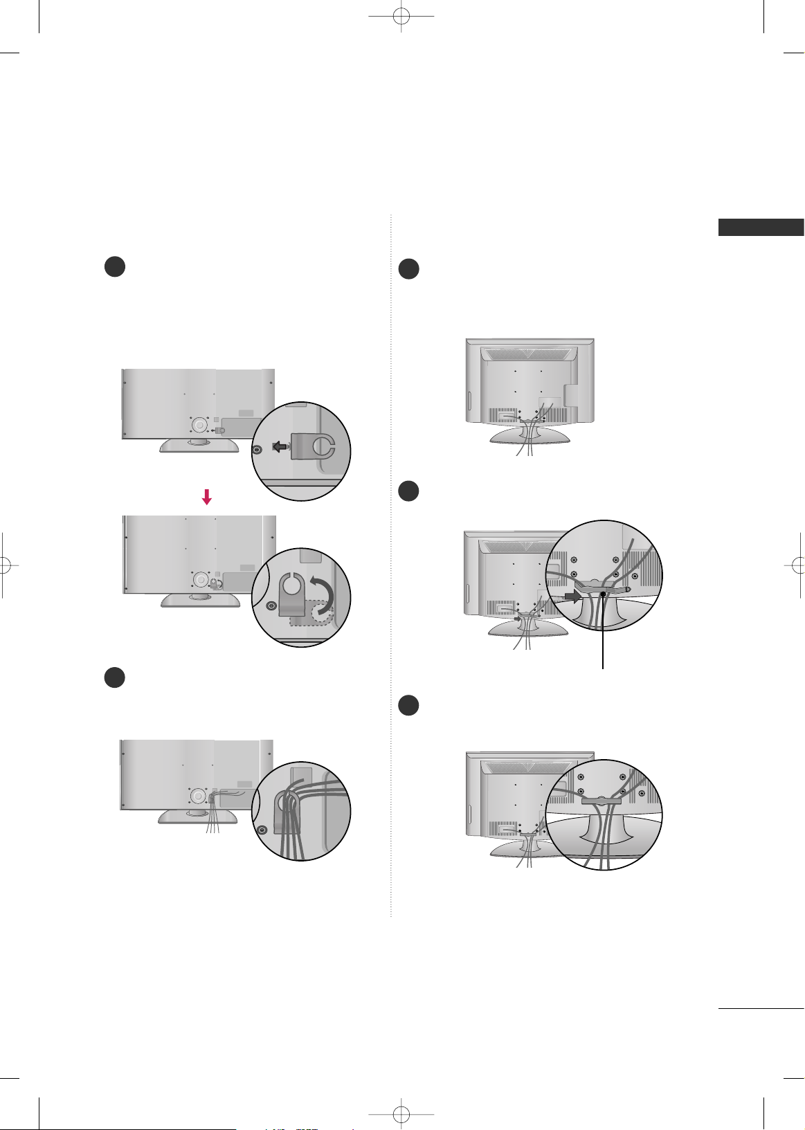
PREPARATION
16
PREPARATION
GG
Do not hold the CABLE MANAGEMENT CLIP when moving the TV.
- If the TV is dropped, you may be injured or the product may be broken.
NOTE
!
Plasma TV Models
50PG60**, 50/60PG70**
CABLE MANAGEMENT CLIP
How to remove the
CABLE MANAGEMENT CLIP
Connect the cables as necessary.
To connect additional equipment, see the EXTERNAL EQUIPMENT SETUP sec-
tion.
Install the CABLE MANAGEMENT CLIP as shown.
1
2
GG
Separate
CCAABBLLEE MMAANN--
AAGGEEMMEENNTT CC LLIIPP
from TV
by pressing two latches.
GG
Hold the CABLE MANAGEMENT CLIP with both
hands and pull it upward.
MFL41469209-Edit1-en 7/29/08 3:52 PM Page 16
Page 19
PREPARATION
17
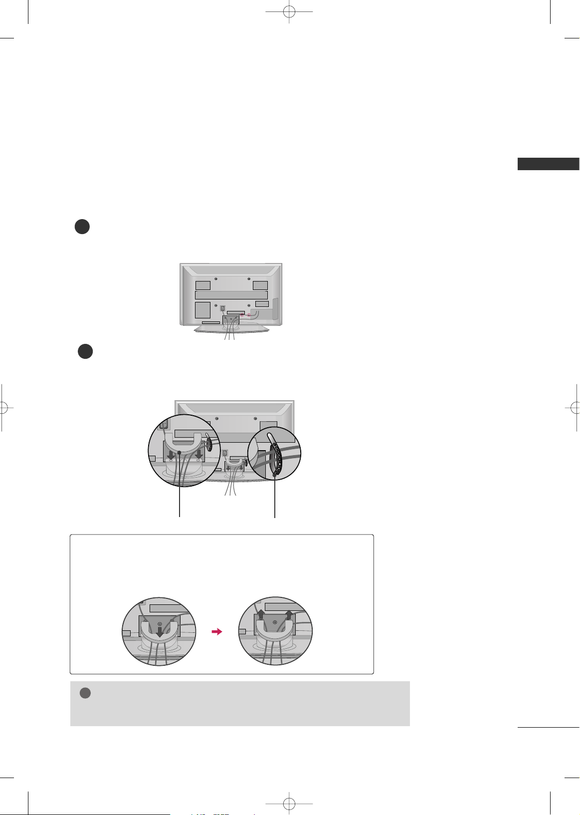
LCD TV Models
Connect the cables as necessary.
To connect additional equipment, see the
EXTERNAL EQUIPMENT SETUP section.
Install the CABLE MANAGEMENT CLIP as
shown.
CABLE MANAGEMENT CLIP
1
2
Align the hole with the tab on the
CCAABBLL EE
MMAANNAAGGEEMMEENNTT CC LLIIPP
.
Turn the
CCAABBLLEE MMAANNAAGGEEMMEENNTT CCLL II PP
as
shown.
Note: This cable management clip can be bro-
ken by excessive pressure.
Connect the cables as necessary.
To connect additional equipment, see the
EXTERNAL EQUIPMENT SETUP section.
1
2
Put the cables inside the CABLE MANAGEMENT
CLIP and snap it closed.
3
32/42LG60** 32LG70**
MFL41469209-Edit1-en 7/29/08 3:52 PM Page 17
Page 20
PREPARATION
18
PREPARATION
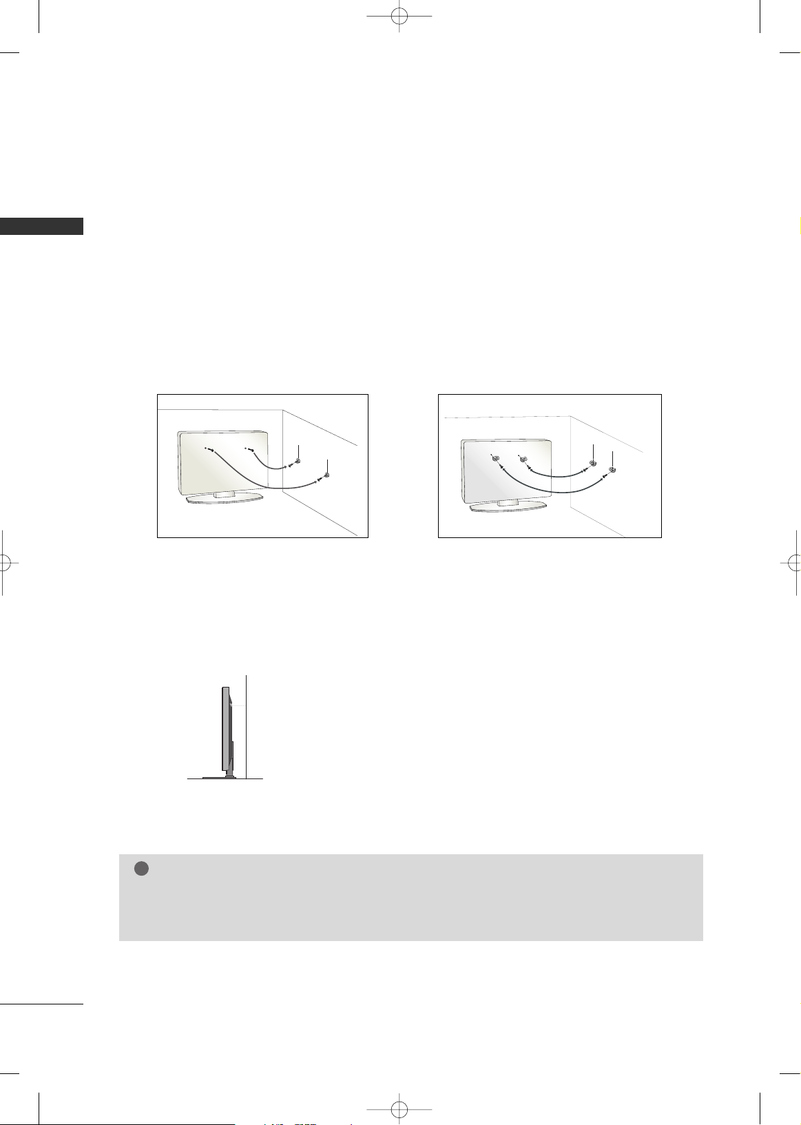
SECURING THE TV TO THE WALL FALL OVER.
This feature is not available for all models.
Here shown may be somewhat different from your TV.
■
Position the TV close to the wall to avoid the possibility of it falling when pushed.
■
The instructions shown below are a safer way to set up the TV, which is to fix it to the wall, avoiding the
possibility of it falling forwards if pulled. This will prevent the TV from falling forward and causing injury.
This will also prevent the TV from damage. Ensure that children do not climb or hang from the TV.
■
You should purchase necessary components to prevent TV from falling off of the stand.
■
Insert the eye-bolts (or TV brackets and bolts) to tighten the product to the wall as shown in the picture.
*If your product has the bolts in the eye-bolts position before inserting the eye-bolts, loosen the bolts.
Secure the wall brackets with the bolts (not provided as parts of the product, must purchase separately) to
the wall. Match the height of the bracket that is mounted on the wall to the holes in the product.
Ensure the eye-bolts or brackets are tightened securely.
■
Use a sturdy rope (not provided as parts of the product, must purchase separately) to tie the product. It is safer to tie the rope so it
becomes horizontal between the wall and the product.
NOTE
!
G
When moving the TV undo the cords first.
G
Use a platform or cabinet strong and large enough to support the size and weight of the TV.
G
To use the TV safely make sure that the height of the bracket on the wall and on the TV is the same.
MFL41469209-Edit1-en 7/29/08 3:52 PM Page 18
Page 21
PREPARATION
19
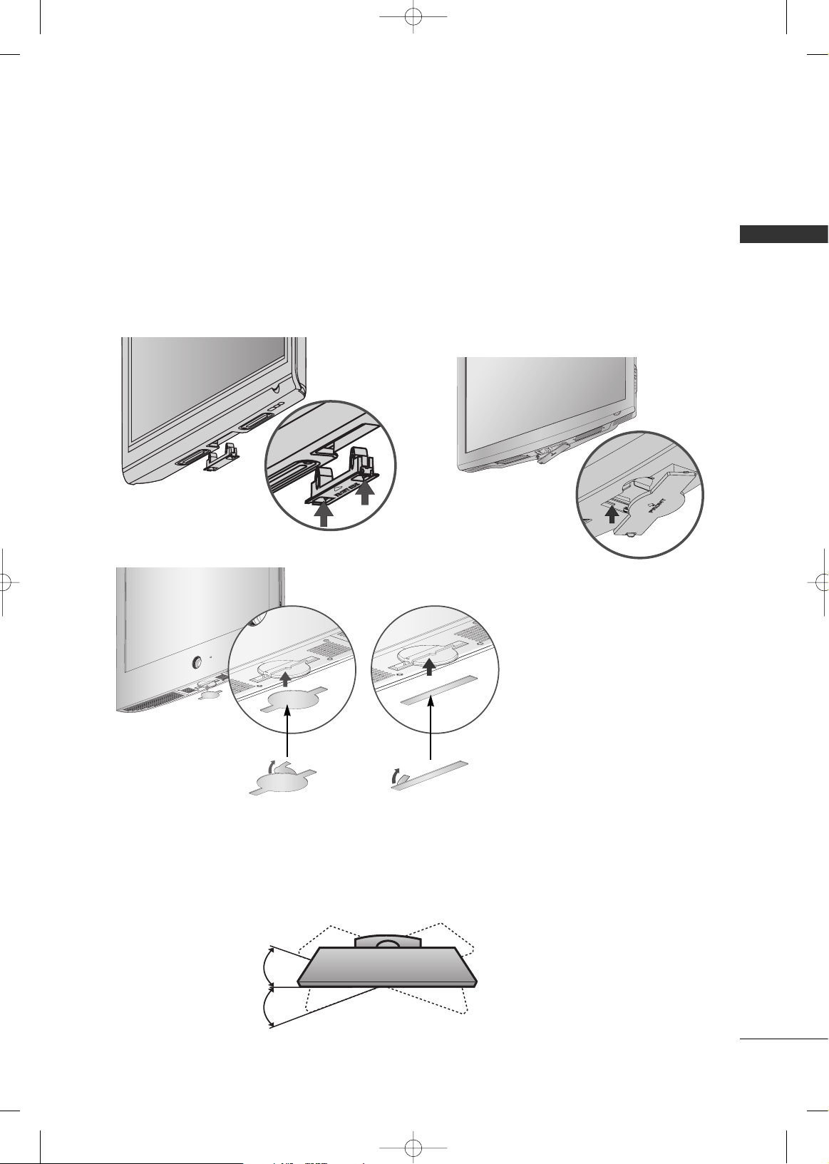
SWIVEL STAND
After installing the TV, you can adjust the TV set manually to the left or right direction by 20 degrees to suit
your viewing position.
PROTECTION COVER
After removing the protection
paper from the protection
cover, adhere it to the TV as
shown.
■
Image shown may differ from your TV.
After removing the stand, install the included
pprrootteeccttiioo nn ccoovveerr
over the hole for the stand.
Press the
PPRROOTTEECCTTIIOONN CCOOVVEERR
into the TV until you hear it click.
Plasma TV Models
LCD TV Models
32/42/47LG60**
LCD TV Models
32LG70**
MFL41469209-Edit1-en 7/29/08 3:52 PM Page 19
Page 22
PREPARATION
20
PREPARATION
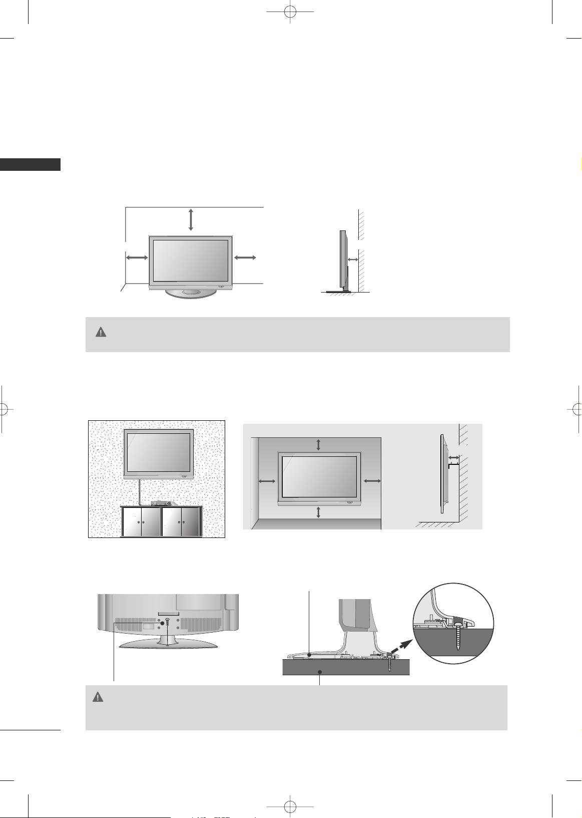
DESKTOP PEDESTAL INSTALLATION
For adequate ventilation allow a clearance of 4” (10cm) all around the TV.
WALL MOUNT: HORIZONTAL INSTALLATION
For adequate ventilation allow a clearance of 4” (10cm) all around the TV. We recommend that you
use an LG brand wall mount when mounting the TV to a wall.
■
This part mainly use picture for Plasma TV model.
4 inches
4 inches
4 inches
4 inches
4 inches
4 inches
4 inches
4 inches
4 inches
ATTACHING THE TV TO A DESK (Only 32LG70**)
The TV must be attached to a desk so it cannot be pulled in a forward/backward direction, potentially causing injury or damaging the product.
1-Screw
(provided as parts of the product)
Stand
GG
Ensure adequate ventilation by following the clearance recommendations.
GG
Do not mount near or above any type of heat source.
CAUTION
GG
To prevent TV from falling over, the TV should be securely attached to the floor/wall per installation
instructions. Tipping, shaking, or rocking the machine may cause injury.
WARNING
MFL41469209-Edit1-en 7/29/08 3:52 PM Page 20
Page 23
PREPARATION
21
ANTENNA
AV IN 2
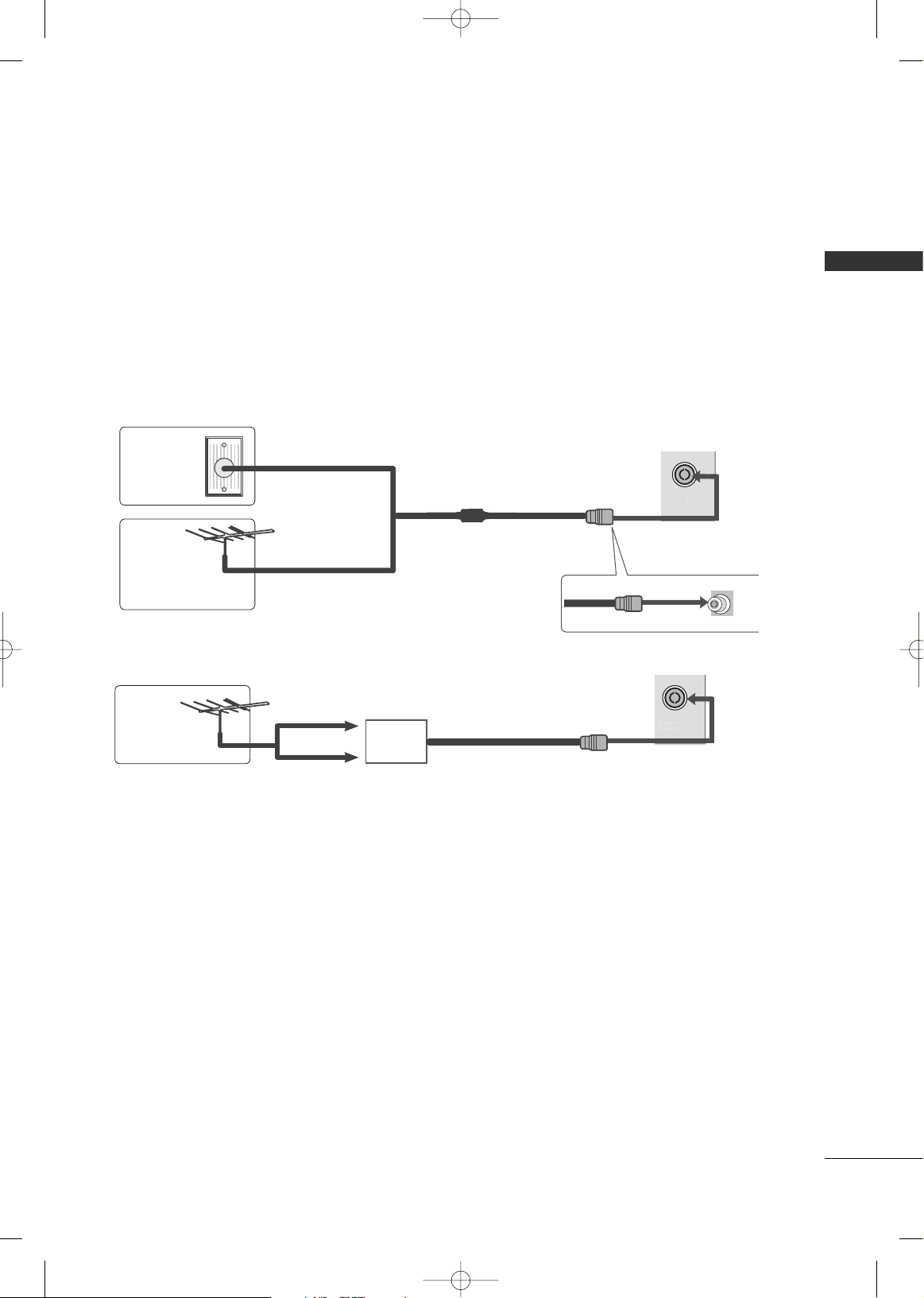
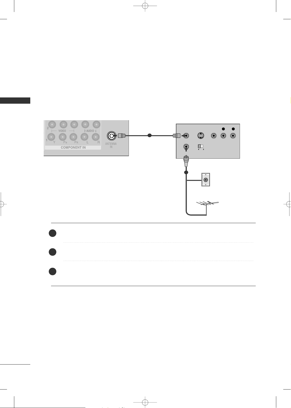
ANTENNA CONNECTION
■
For optimum picture quality, adjust antenna direction.
■
An antenna cable and converter are not supplied.
Multi-family Dwellings/Apartments
(Connect to wall antenna socket)
Single-family Dwellings /Houses
(Connect to wall jack for outdoor antenna)
Outdoor
Antenna
Wall
Antenna
Socket
RF Coaxial Wire (75 ohm)
Antenna
UHF
VHF
■
In poor signal areas, to achieve better picture quality it may be necessary to install a signal amplifier to the
antenna as shown above.
■
If signal needs to be split for two TVs, use an antenna signal splitter for connection.
■
To prevent damage do not connect to the mains outlet until all connections are made between the devices.
ANTENNA
AV IN 2
Signal
Amplifier
MFL41469209-Edit1-en 7/29/08 3:52 PM Page 21
Page 24
EXTERNAL EQUIPMENT SETUP
22
EXTERNAL EQUIPMENT SETUP
HDMI IN HDMI DVI IN
HDMI/DVI IN
1
1
2
COMPONENT IN
VIDEO
AUDIO
L/MONO
R
AUDIO
VIDEO
1 2
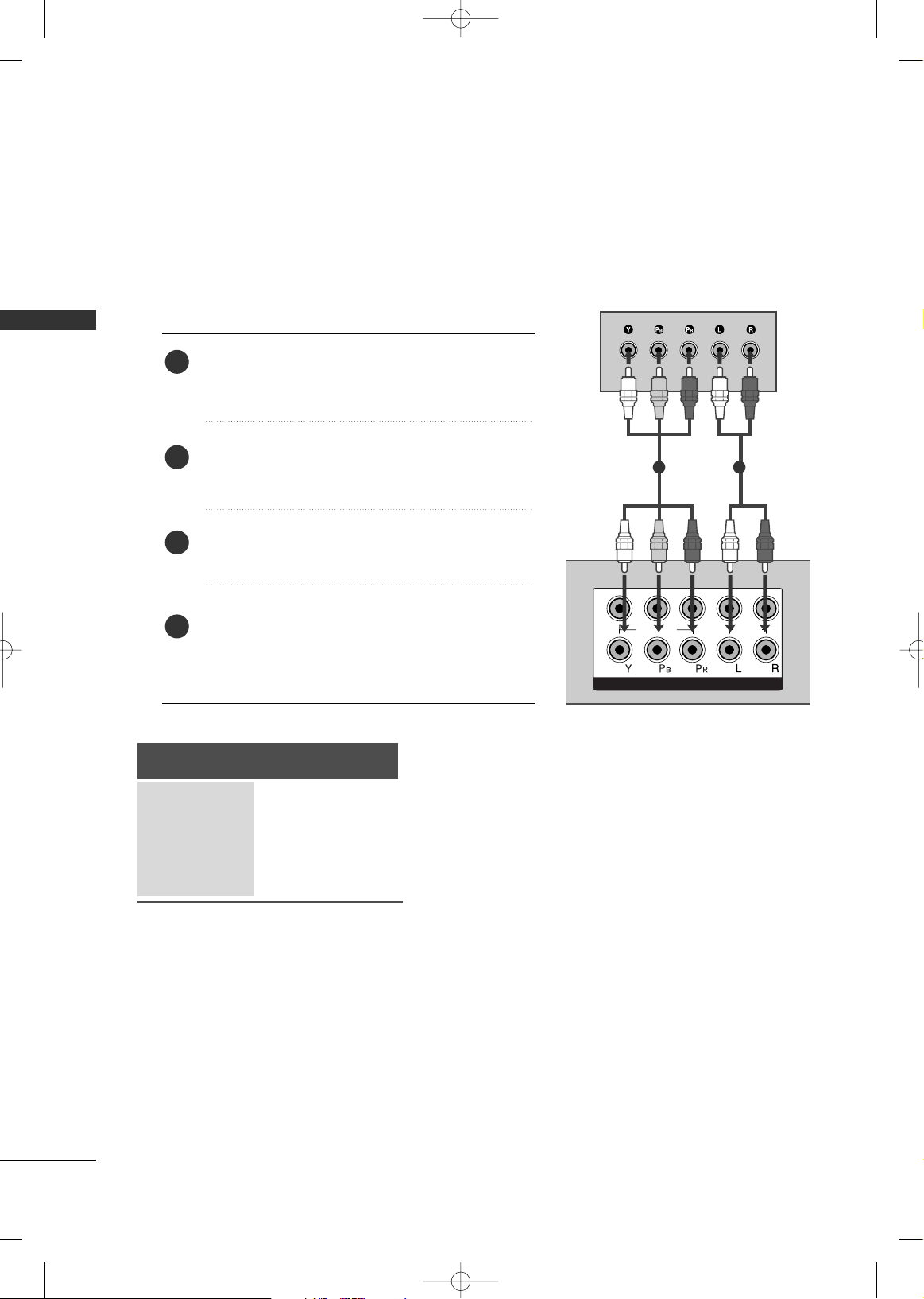
HD RECEIVER SETUP
When connecting with a component cable
Connect the video outputs (Y, PB, PR
)
of the digital set
top box to the
CCOOMMPPOONNEENNTT II NN VVIIDDEEOO
jacks on the
TV.
Connect the audio output of the digital set-top box to
the
CCOOMMPPOONNEENNTT II NN AAUUDD IIOO
jacks on the TV.
Turn on the digital set-top box.
(
Refer to the owner’s manual for the digital set-top box.
)
Select
CC oommpp oonneenntt 11
input source using the
IINN PPUUTT
button on the remote control.
If connected to
CCOOMMPPOONNEENNTT IINN 22
, select
CC oommpp oonneenntt 22
input source.
2
3
4
1
■
To avoid damaging any equipment, never plug in any power cords until you have finished connecting all equipment.
■
This section on EXTERNAL EQUIPMENT SETUP mainly uses diagrams for the Plasma TV models.
■
Image shown may differ from your TV.
Signal
480i/576i
480p/576p
720p/1080i
10 8 0 p
Component
Yes
Yes
Yes
Yes
(Only 50Hz, 60Hz)
MFL41469209-Edit1-en 7/29/08 3:52 PM Page 22
Page 25
EXTERNAL EQUIPMENT SETUP
23
HDMI IN HDMI DVI IN
HDMI/DVI IN
1
HDMI IN HDMI DVI IN
HDMI IN HDMI IN HDMI/DVI IN HDMI/DVI IN
1 2
L/MONO
R
AUDIO
VIDEO
L/L/MONOMONO
R
AUDIOAUDIO
IN 1
VIDEOVIDEO
OUT
VARIABLE AUDIO
AV
1
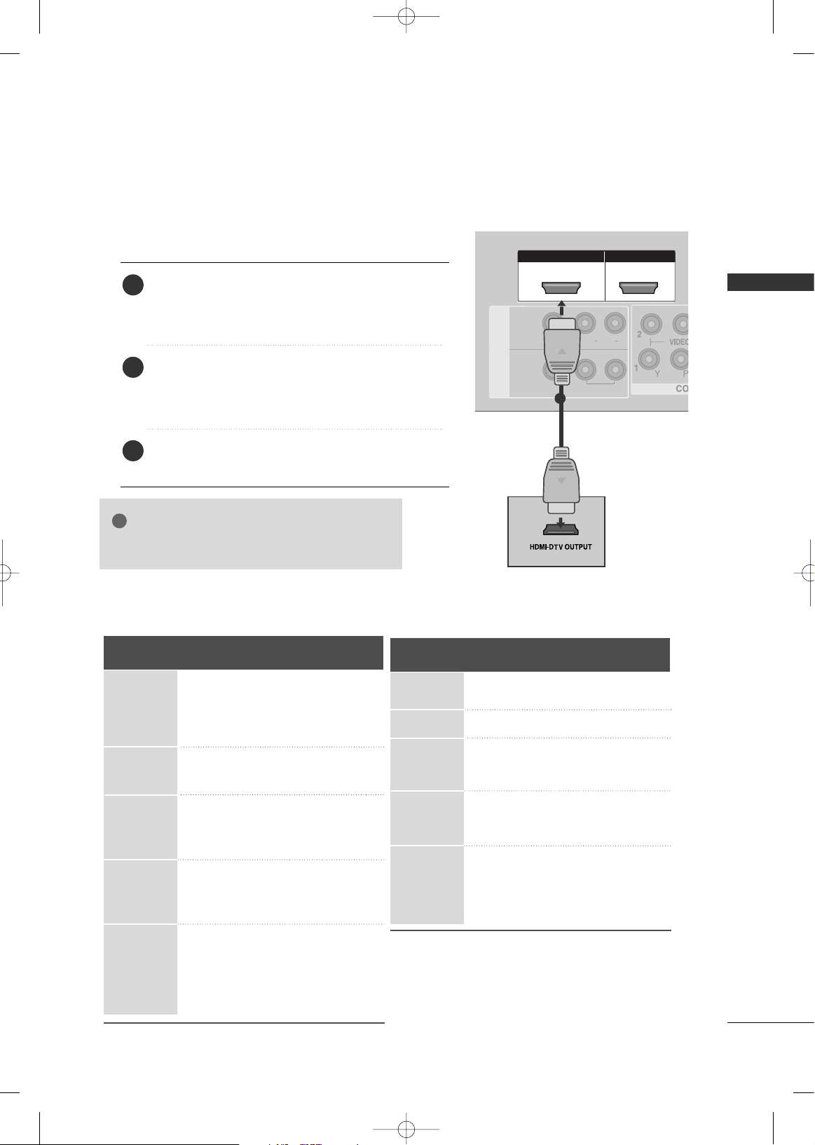
When connecting with a HDMI cable
Connect the HDMI output of the digital set-top box to the
HHDDMMII//DDVVII IINN 11,, HHDDMMII IINN 22 orHHDDMMII IINN 33
(Except
32LG60**) jack on the TV.
Select
HHDDMMII11//DD VVII ,, HHDD MMII 22
or
HHDDMMII33
(Except
32LG60**) input source using the
IINN PPUUTT
button on
the remote control.
Turn on the digital set-top box.
(
Refer to the owner’s manual for the digital set-top box.
)
2
3
1
GG
TV can receive the video and audio signal simultaneously with using a HDMI cable.
NOTE
!
Resolution
720x480
720x576
1280x720
1920x1080i
1920x1080p
HDMI-DTV mode
Horizontal Vertical
Frequency(kHz) Frequency(Hz)
31.47 59.94
31.50 60.00
31.25 50.00
44.96 59.94
45.00 60.00
37.50 50.00
33.72 59.94
33.75 60.00
28.125 50.00
67.432 59.94
67.50 60.00
56.25 50.00
27.0 24. 00
33.75 30.00
Plasma TV Models
LCD TV Models
Resolution
720x480
720x576
1280x720
1920x1080i
1920x1080p
Horizontal Vertical
Frequency(kHz) Frequency(Hz)
31.47 59.94
31.50 60.00
31.25 50.00
44.96 59.94
45.00 60.00
37.50 50.00
33.72 59.94
33.75 60.00
28.125 50.00
67.432 59.94
67.50 60.00
56.25 50.00
27.00 24.00
33.75 30.00
MFL41469209-Edit1-en 7/29/08 3:52 PM Page 23
Page 26
EXTERNAL EQUIPMENT SETUP
24
EXTERNAL EQUIPMENT SETUP
HDMI IN HDMI IN HDMI DVI IN HDMI DVI IN
HDMI/DVI IN
1
AUDIO
(RGB/DVI)
RGB
(PC)
RGB IN
RS-232C IN
(CONTROL)
L/L/MONOMONO
R
AUDIOAUDIO
IN 1
VIDEOVIDEO
OUT
AV
VARIABLE AUDIO
1
2
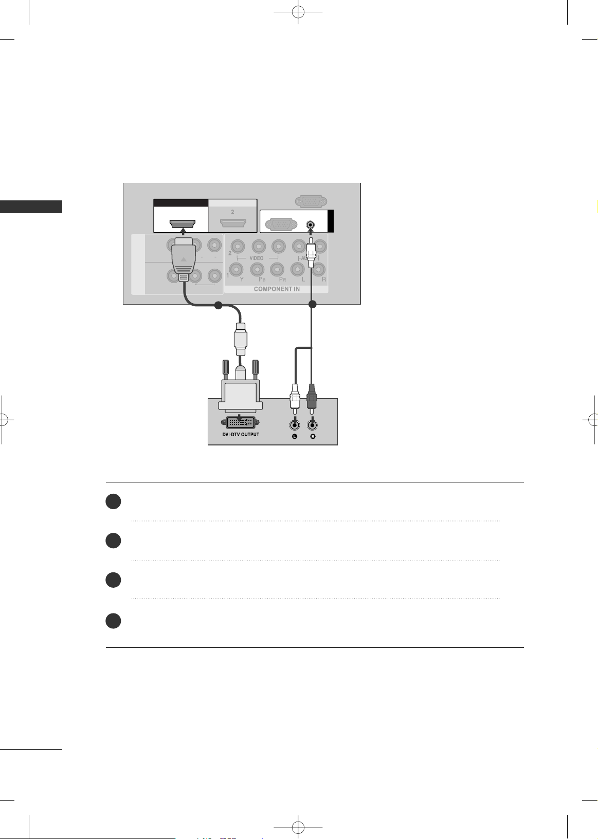
Connect the DVI output of the digital set-top box to the
HHDDMMII//DD VVII IINN 11
jack on the TV.
Connect the audio output of the digital set-top box to the
AAUU DDIIOO((RRGGBB//DD VVII))
jack on the TV.
Turn on the digital set-top box. (Refer to the owner’s manual for the digital set-top box.
)
Select
HHDDMMII11//DD VVII
input source using the
IINN PPUUTT
button on the remote control.
2
3
4
1
When connecting with a HDMI to DVI cable
MFL41469209-Edit1-en 7/29/08 3:52 PM Page 24
Page 27
EXTERNAL EQUIPMENT SETUP
25
1
2
COMPONENT IN
VIDEO
AUDIO
1 2
DVD SETUP
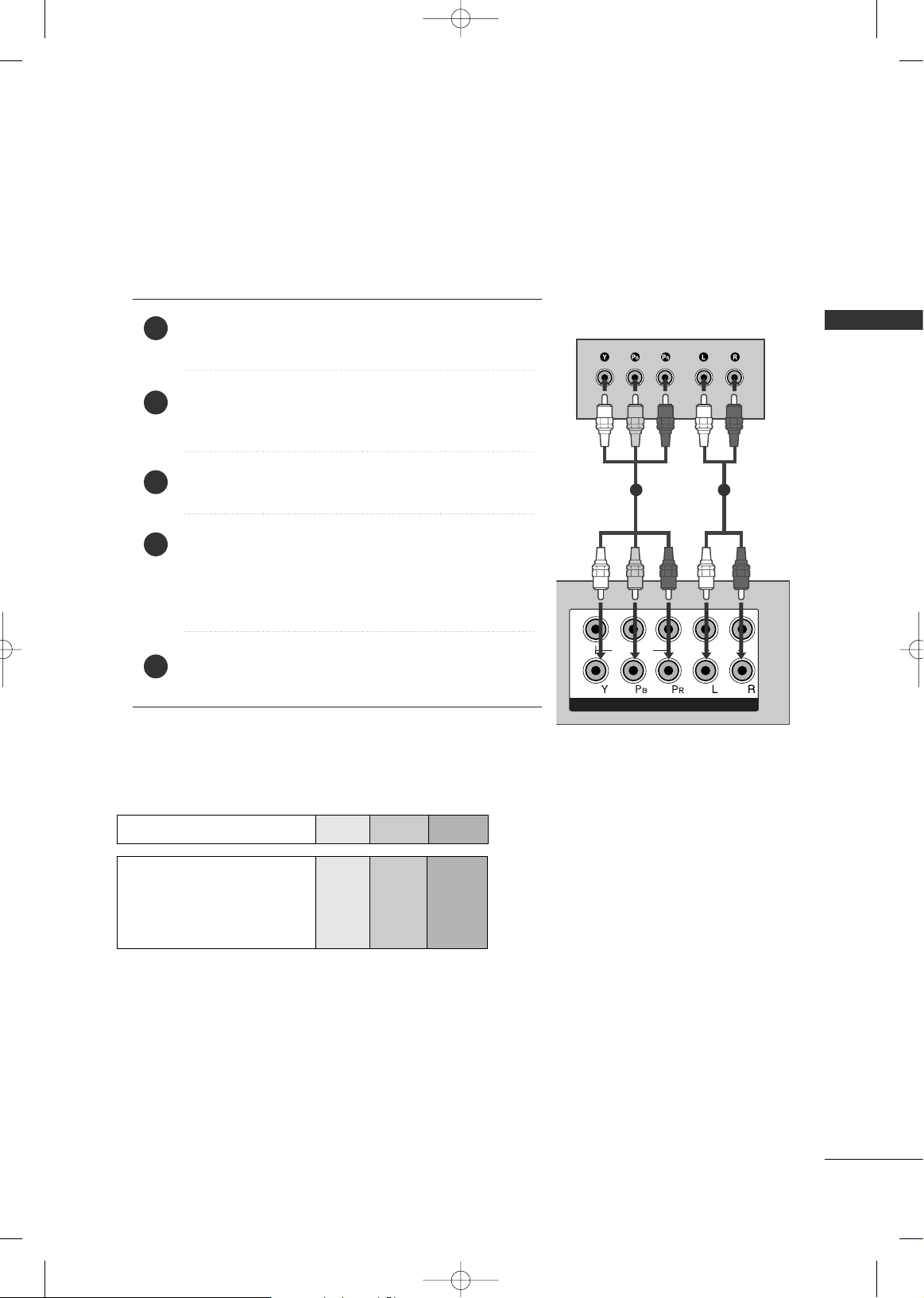
When connecting with a component cable
Component Input ports
To achieve better picture quality, connect a DVD player to the component input ports as shown below.
Component ports on the TV
YPB PR
Video output ports
on DVD player
Y
Y
Y
Y
P
B
B-Y
Cb
Pb
P
R
R-Y
Cr
Pr
Connect the video outputs (Y, P
B, PR
)
of the DVD to the
CCOOMMPPOONNEENNTT II NN VVIIDDEEOO
jacks on the TV.
Connect the audio outputs of the DVD to the
CCOO MMPPOO--
NN EENNTT IINN AAUUDDIIOO
jacks on the TV.
Turn on the DVD player, insert a DVD.
Select
CC oommpp oonneenntt 11
input source using the
IINN PPUUTT
button on
the remote control.
If connected to
CCOOMMPPOONNEENNTT IINN 22
, select Component
2
input source.
Refer to the DVD player's manual for operating instructions.
2
3
4
5
1
MFL41469209-Edit1-en 7/29/08 3:52 PM Page 25
Page 28
EXTERNAL EQUIPMENT SETUP
26
EXTERNAL EQUIPMENT SETUP
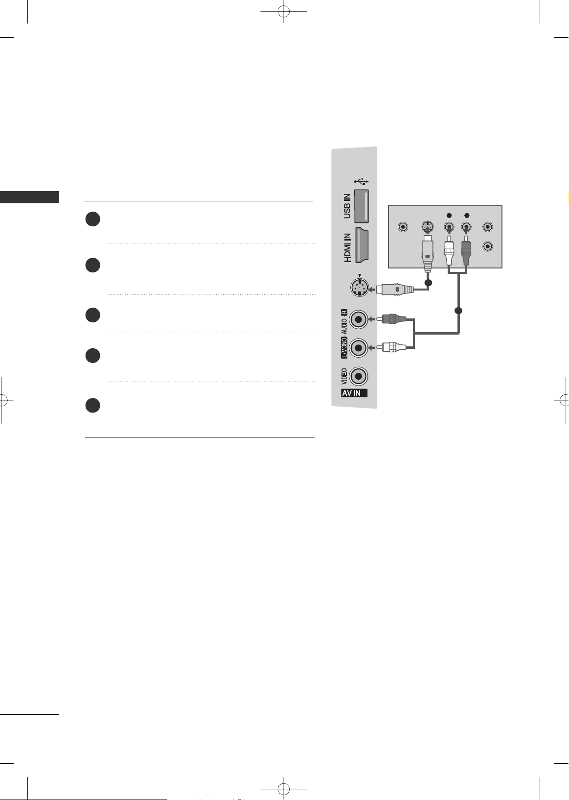
When connecting with an S-Video cable
Connect the S-VIDEO output of the DVD to the
SS --
VVIIDD EEOO
input on the TV.
Connect the audio outputs of the DVD to the
AAUU DDIIOO
input jacks on the TV.
Turn on the DVD player, insert a DVD.
Select
AAVV22
input source using the
IINN PPUUTT
button on
the remote control.
Refer to the DVD player's manual for operating
instructions.
2
3
4
5
1
1
2
MFL41469209-Edit1-en 7/29/08 3:52 PM Page 26
3
S-VIDEO
2
S-VIDEOVIDEO
OUTPUT
SWITCH
L R
ANT IN
ANT OUT
Page 29
EXTERNAL EQUIPMENT SETUP
27
HDMI IN HDMI DVI IN
HDMI IN HDMI IN HDMI/DVI IN HDMI/DVI IN
1 2
HDMI IN HDMI DVI IN
AV IN 2
L/L/MONOMONO
R
AUDIOAUDIO
IN 1
VIDEOVIDEO
OUT
VARIABLE AUDIO
AV
( )
1
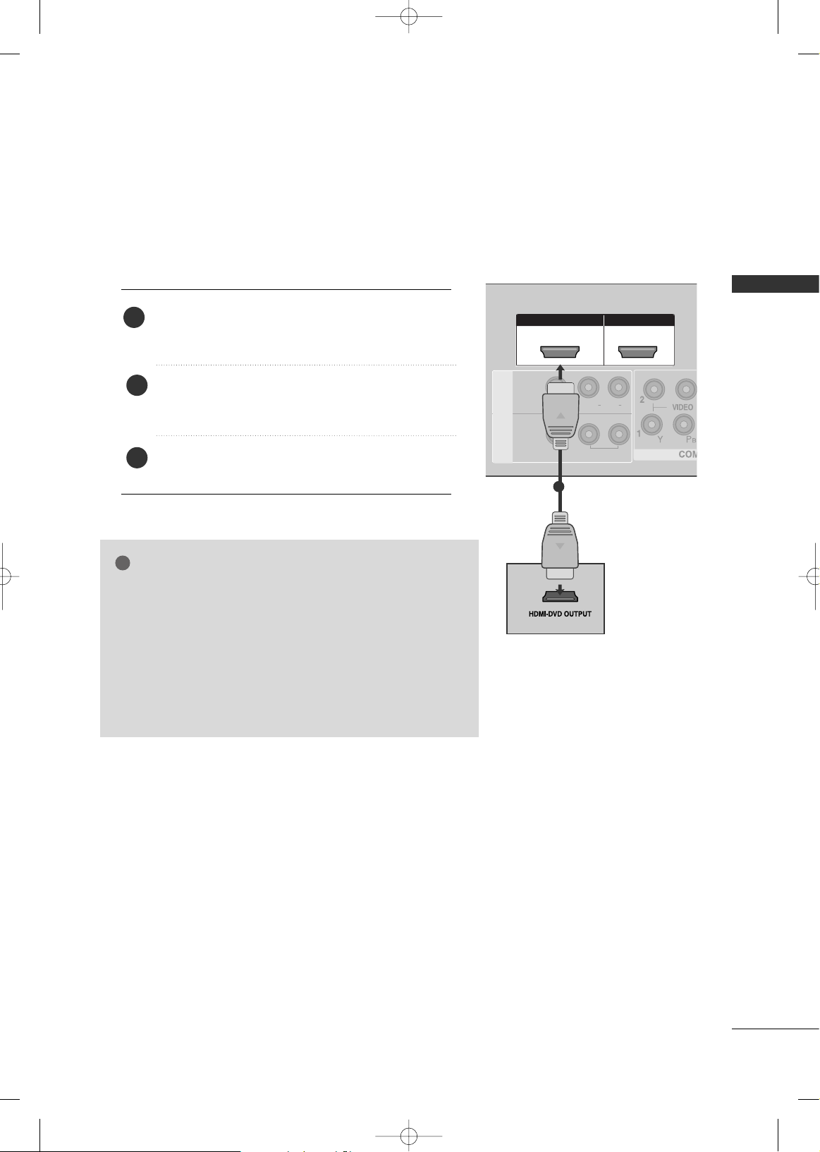
When connecting HDMI cable
Connect the HDMI output of the DVD to the
HHDDMMII//DDVVII IINN 11,HHDDMMII IINN 22
or
HHDDMMII IINN 33
(Except
32LG60**) jack on the TV.
Select
HHDDMMII11//DD VVII, HHDDMMII22
or
HHDDMMII33
(Except
32LG60**) input source using the
IINN PPUUTT
button on
the remote control.
Refer to the DVD player's manual for operating instructions.
1
GG
TV can receive the video and audio signal simultaneously with
using a HDMI cable.
GG
If the DVD supports Auto HDMI function, the output resolution
of the source device will be automatically set to 1280x720p.
GG
If the DVD player does not support Auto HDMI, you need to
set the DVD output resolution appropriately.
To get the best picture quality, adjust the output resolution of
the source device to 1280x720p.
(42/47LG60**, 50/60PG70**: 1920X1080i/1080p)
NOTE
!
2
3
MFL41469209-Edit1-en 7/29/08 3:52 PM Page 27
Page 30
EXTERNAL EQUIPMENT SETUP
28
EXTERNAL EQUIPMENT SETUP
HDMI IN HDMI DVI IN
ANTENNA
IN
OUTPUT
SWITCH
ANT IN
R
S-VIDEO VIDEO
ANT OUT
L
Wall Jack
Antenna
1
2
VCR SETUP
When connecting with an antenna
■
To avoid picture noise (interference), allow adequate distance between the VCR and TV.
■
Typically a frozen still picture from a VCR. If 4:3 picture format is used for an extended period the fixed
images on the sides of the screen may remain visible.
Connect the ANT OUT socket of the VCR to the
AANNTTEENN NNAA IINN
socket on the TV.
Connect the antenna cable to the ANT IN socket of the VCR.
Press the PLAY button on the VCR and match the appropriate program between the TV and VCR for
viewing.
1
2
2
3
1
MFL41469209-Edit1-en 7/29/08 3:52 PM Page 28
Page 31

EXTERNAL EQUIPMENT SETUP
29
When connecting with a RCA cable
L/MONO
R
AUDIO
VIDEO
VIDEO
L
R
AUDIO
HDMI IN HDMI DVI IN
HDMI IN HDMI DVI IN
OUT
VARIABLE AUDIO OUTVARIABLE AUDIO OUT
L
R
S-VIDEO
VIDEO
OUTPUT
SWITCH
ANT IN
ANT OUT
VIDEO
MONO
( )
AUDIO
IN 1
AV
Connect the
AAUU DDIIOO/VVIIDD EEOO
jacks between TV and VCR. Match the jack colors (Video = yellow,
Audio Left = white, and Audio Right = red)
Insert a video tape into the VCR and press PLAY on the VCR. (Refer to the VCR owner’s manual.
)
Select
AAVV11
input source using the
IINN PPUUTT
button on the remote control.
If connected to
AAVV IINN22
, select
AAVV22
input source.
1
2
3
GG
If you have a mono VCR, connect the audio cable from the VCR to the
AAUU DD II OO LL// MMOONNOO
jack
of the TV.
NOTE
!
1
MFL41469209-Edit1-en 7/29/08 3:52 PM Page 29
Page 32

EXTERNAL EQUIPMENT SETUP
30
EXTERNAL EQUIPMENT SETUP
GG
If both S-VIDEO and VIDEO sockets have been conneced to
the S-VHS VCR simultaneously, only the S-VIDEO can be
received.
NOTE
!
When connecting with an S-Video cable
Connect the S-VIDEO output of the VCR to the
SS --
VVIIDDEEOO
input on the TV. The picture quality is
improved; compared to normal composite (RCA cable)
input.
Connect the audio outputs of the VCR to the
AAUU DDIIOO
input jacks on the TV.
Insert a video tape into the VCR and press PLAY on
the VCR. (Refer to the VCR owner’s manual.)
Select
AAVV22
input source using the
IINN PPUUTT
button on
the remote control.
2
3
4
1
1
2
MFL41469209-Edit1-en 7/29/08 3:52 PM Page 30
3
S-VIDEO
S-VIDEOVIDEO
OUTPUT
SWITCH
L R
ANT IN
ANT OUT
Page 33

EXTERNAL EQUIPMENT SETUP
31
S-VIDEO
3
L R
VIDEO
Camcorder
Video Game Set
1
OTHER A/V SOURCE SETUP
Connect the
AAUU DDIIOO/VVIIDD EEOO
jacks between TV and external equipment. Match the jack colors
.
(
Video = yellow, Audio Left = white, and Audio Right = red
)
Select
AAVV22
input source using the
IINN PPUUTT
button on the remote control.
If connected to
AAVV IINN11
, select
AAVV11
input source.
Operate the corresponding external equipment.
Refer to external equipment operating guide.
1
2
3
MFL41469209-Edit1-en 7/29/08 3:52 PM Page 31
Page 34

EXTERNAL EQUIPMENT SETUP
32
EXTERNAL EQUIPMENT SETUP
HDMI IN HDMI IN HDMI DVI IN HDMI DVI IN
AUDIO
(RGB/DVI)
RGB
(PC)
RGB IN
HDMI IN HDMI DVI IN
HDMI/DVI IN
1
L/L/MONOMONO
R
AUDIOAUDIO
IN 1
VIDEOVIDEO
OUT
VARIABLE AUDIO
AV
RGB OUTPUT
AUDIO
L/MONO
R
AUDIO
VIDEO
1
2
PC SETUP
This TV provides Plug and Play capability, meaning that the PC adjusts automatically to the TV's settings.
Connecting with a D-sub 15 pin cable
Connect the RGB output of the PC to the
RRGGBB ((PP CC
))
jack on the TV.
Connect the PC audio output to the
AAUU DDIIOO((RRGGBB//DD VVII))
jack on the TV.
Turn on the PC and the TV.
Select
RRGG BB PPCC
input source using the
IINN PPUUTT
button on the remote control.
2
3
4
1
MFL41469209-Edit1-en 7/29/08 3:52 PM Page 32
Page 35

EXTERNAL EQUIPMENT SETUP
33
GG
To enjoy vivid picture and sound, connect the PC
to the TV.
GG
Avoid keeping a fixed image on the TV ’s screen
for prolonged periods of time.The fixed image
may become permanently imprinted on the
screen;use a screen saver when possible.
GG
Connect the PC to the RGB (PC) port of the TV;
change the resolution output of PC accordingly.
GG
There may be interference relating to resolution,
vertical pattern, contrast or brightness in PC
mode. Change the PC mode to another resolution or change the refresh rate to another rate or
adjust the brightness and contrast on the menu
until the picture is clear. If the refresh rate of the
PC graphic card can not be changed, change the
PC graphic card or consult the manufacturer of
the PC graphic card.
GG
The synchronization input waveform for
Horizontal and Vertical frequencies are separate.
GG
If the resolution of PC is over SXGA, there will be
no picture on the TV.(Only HD Models)
GG
Connect the audio cable from the PC to the
Audio input on the TV.(Audio cables are not
included with the TV).
GG
If you use too long an RGB-PC cable, there may
be interference on the screen. We recommend
using under 5m of the cable. This provides the
best picture quality.
NOTES
!
Supported Display Resolution (RGB-PC mode)
Resolution
Only 50PG60**
Plasma TV Models
Resolution
LCD TV Models
Only 50/60PG70**
Horizontal Vertical
Frequency(kHz) Frequency(Hz)
31.468 70.09
31.469 70.09
31.469 59.94
37.879 60.317
48.363 60.004
47.776 59.87
47.720 59. 799
47.700 6 0. 00
63.668 59.895
66.587 59.934
640x 350
720x400
640x480
800x600
1024x768
1280x768
1360x768
1366x768
1280x1024
1400x1050
1600x1200
1920x1080
Horizontal Vertical
Frequency(kHz) Frequency(Hz)
31.468 70.09
31.469 70.09
31.469 59.94
37.879 60.317
48.363 60.004
47.776 59 .87
47.720 59. 799
47.7 60.0
63.668 59.895
65.317 59.978
74.537 59.869
66.587 59.934
640x350
720x400
640x480
800x600
1024x768
1280x768
1360x768
1366x768
1280x1024
1920x1080
Only 42/47LG60
**
MFL41469209-Edit1-en 7/29/08 3:52 PM Page 33
Page 36

EXTERNAL EQUIPMENT SETUP
34
EXTERNAL EQUIPMENT SETUP
SCREEN SETUP FOR PC MODE
Auto Configure (RGB [PC] mode only)
Press the
MMEENNUU
button and then use or button
to select the
PPiiccttuurree
menu.
Press the button and then use or button to
select
SSccrreeeenn
.
Press the button and then use or button to
select
AAuuttoo CCoonnffii gg..
.
Press the button to start
AAuuttoo CCoonnffii gg..
.
■
When Auto config. has finished, OK will be shown on
screen.
■
If the position of the image is still not correct, try
Auto adjustment again.
If picture needs to be adjusted again after Auto adjustment in RGB (PC), you can adjust the
MMaa nnuuaall
CCoo nnffiigg ..
.
Press the
MMEENNUU
button to return to TV viewing.
Press the
RREETTUU RR NN
button to move to the previous
menu.
2
1
4
5
3
6
Automatically adjusts picture position and minimizes image
instability. After adjustment, if the image is still not correct, your TV is functioning properly but needs further
adjustment.
AAuuttoo cc oonnffiigguu rr ee
This function is for the automatic adjustment of the screen
position, clock, and phase. The displayed image will be unstable for a few seconds while the auto configuration is in
progress.
1
Picture Mode
Color Temperature
Advanced
Aspect Ratio
Picture Reset
Screen
Picture
DE F G
RETURN
2
Picture
Picture Mode
Color Temperature
Advanced
Aspect Ratio
Picture Reset
Screen
To Set
Screen G
DE F G
RETURN
3 4
Screen
Auto config.
Manual Config.
XGA Mode
Reset
To Set
Auto Config. G
DE F G
RETURN
MFL41469209-Edit1-en 7/29/08 3:52 PM Page 34
Page 37

EXTERNAL EQUIPMENT SETUP
35
Manual Configure - Adjustment for screen Phase, Clock, Position
(RGB [PC] mode only)
Press the
MMEENNUU
button and then use or button
to select the
PPiiccttuurree
menu.
Press the button and then use or button to
select
SSccrreeeenn
.
Press the button and then use or button to
select
MMaannuuaa ll CCoonnffii gg..
.
Press the button and then use or button to
select
PPhhaassee, CCll oocckk, HH--PPoossiittiioonn, VV--PPoossiittiioo nn
.
Press the or button to make appropriate adjustments.
Press the
MMEENNUU
button to return to TV viewing.
Press the
RREETTUU R
RNN
button to move to the previous
menu.
2
1
4
5
3
6
If the picture isn’t clear after auto adjustment and especially if characters
are still trembling, adjust the picture phase manually.
It’s not available to use Phase, Clock function in
COMPONENT(480i/480p/576i/576p/720p/1080i/1080p), HDMI
(480p/576p/720p/1080i/1080p).
CCll oocckk
This function is to minimize any vertical bars or stripes visible
on the screen background. And the horizontal screen size will
also change.
PPhhaassee
This function allows you to remove any horizontal noise and
clear or sharpen the image of characters.
1
Picture Mode
Color Temperature
Advanced
Aspect Ratio
Picture Reset
Screen
Picture
DE F G
RETURN
2
Picture
Picture Mode
Color Temperature
Advanced
Aspect Ratio
Picture Reset
Screen
To Set
Screen G
DE F G
RETURN
3 4 5
Screen
Auto config.
Manual Config.
XGA Mode
Reset
Manual Config. G
DE F G
RETURN
Phase 51
Clock 50
H-Position 50
V-Position 50
MFL41469209-Edit1-en 7/29/08 3:52 PM Page 35
Page 38

EXTERNAL EQUIPMENT SETUP
36
EXTERNAL EQUIPMENT SETUP
Selecting XGA mode
- Except 42PG60**
Press the
MMEENNUU
button and then use or button
to select the
PPiiccttuurree
menu.
Press the button and then use or button to
select
SSccrreeeenn
.
Press the button and then use or button to
select
XXGG AA MMooddee
.
Press the button and then use or button to
select the desired XGA resolution.
Press the
MMEENNUU
button to return to TV viewing.
Press the
RREETTUU RR NN
button to move to the previous
menu.
2
1
4
5
3
To see a normal picture, match the resolution of RGB mode and selection of XGA mode.
This function works in the following mode: RGB[PC] mode.
1
Picture Mode
Color Temperature
Advanced
Aspect Ratio
Picture Reset
Screen
Picture
DE F G
RETURN
2
Picture
Picture Mode
Color Temperature
Advanced
Aspect Ratio
Picture Reset
Screen
To Set
Screen G
DE F G
RETURN
3 4
Screen
Auto config.
Manual Config.
XGA Mode
Reset
XGA Mode G
DE F G
RETURN
1024x768
1280x768
1360x768
1366x768
* Except 50PG60**
MFL41469209-Edit1-en 7/29/08 3:52 PM Page 36
Page 39

EXTERNAL EQUIPMENT SETUP
37
Initializing (Reset to original factory settings)
Press the
MMEENNUU
button and then use or button
to select the
PPiiccttuurree
menu.
Press the button and then use or button to
select
SSccrreeeenn
.
Press the button and then use or button to
select
RReess ee tt
.
Press the button.
Press the
MMEENNUU
button to return to TV viewing.
Press the
RREETTUU RR NN
button to move to the previous
menu.
2
1
4
5
3
This function operates in current mode.
To initialize the adjusted value.
DE F G
RETURN
1
Picture Mode
Color Temperature
Advanced
Aspect Ratio
Picture Reset
Screen
Picture
DE F G
RETURN
2
Picture
Picture Mode
Color Temperature
Advanced
Aspect Ratio
Picture Reset
Screen
To Set
Screen G
DE F G
RETURN
3 4
Screen
Auto config.
Manual Config.
XGA Mode
Reset
Reset G
DE F G
RETURN
To Set
MFL41469209-Edit1-en 7/29/08 3:52 PM Page 37
Page 40

EXTERNAL EQUIPMENT SETUP
38
EXTERNAL EQUIPMENT SETUP
USB IN SETUP
AV IN 2AV IN 2
AV IN 2
3
Connect the USB device to the
UUSS BB IINN
jacks on the side of TV.
After connecting the
UUSS BB IINN
jacks, you use the USB function. (
GG
pp..5544
)
2
1
1
MFL41469209-Edit1-en 7/29/08 3:52 PM Page 38
Page 41

EXTERNAL EQUIPMENT SETUP
39
EXTERNAL STEREO SETUP
HDMI IN HDMI DVI IN
HDMI IN HDMI DVI IN
VIDEO
MONOMONO
( )
AUDIO
IN 1
AV
VIDEO
MONO
( )
AUDIO
IN 1
OUT
VARIABLE AUDIO OUT
GG
When connecting with external audio equipments, such as
amplifiers or speakers, please turn the TV speakers off.
GG
Select
VVaarriiaabbllee OOuutt
in Audio menu to connect the
VVAARR II--
AABBLL EE AAUUDDIIOO OO UU TT
jacks.(
GG
pp..8833
)
NOTE
!
Use to connected either an external amplifier, or add a subwoofer to your surround sound system.
Connect the input jack of the stereo amplifier to the
VVAARRIIAABBLLEE AAUUDDIIOO OOUU TT
jacks on the TV.
Set up your speakers through your analog stereo
amplifier, according to the instructions provided with
the amplifier.
2
1
11
AV OUT SETUP
The TV has a special signal output capability which allows you
to hook up the second TV or monitor.
HDMI IN HDMI DVI IN
VIDEO
MONOMONO
( )
AUDIO
IN 1
AV
OUT
VARIABLE AUDIO OUT
OUT
VARIABLE AUDIO OUT
L R
S-VIDEO
VIDEO
Connect the second TV or monitor to the TV’s
AAVV OOUUTT
jacks.
See the Operating Manual of the second TV or monitor
for further details regarding that device’s input settings.
GG
Component, RGB, HDMI input sources cannot be used for
AV out.
GG
We recommend to use the AV OUT jacks for VCR recording.
NOTE
!
2
1
1
MFL41469209-Edit1-en 7/29/08 3:52 PM Page 39
Page 42

WATCHING TV / CHANNEL CONTROL
40
WATCHING TV / CHANNEL CONTROL
MUTE
RETURN
AV MODE
FAV
TV
POWER
Q. MENU
MENU
ENTER
VOL
CH
123
456
7809
Q.VIEW
DVD
INPUT
STB
PIP
Q. MENU
MENU
Select the desired quick menu source.
GG
pp..4433
Displays the main menu.
Clear all on-screen displays and return to TV viewing from
any menu.
See a list of AV devices connected to TV.
When you toggle this button, the Simplink menu
appears at the screen.
GG
pp..5522
TV/DVD/STB
INPUT
Select the remote operating mode: TV, DVD, or STB.
External input modes rotate in regular sequence.
VOLUME UP
/DOWN
FAV
MUTE
CH
UP/DOWN
0~9 number
button
Q.VIEW
PIP
Increase/decrease in the sound level.
Scroll through the programmed favorite channels.
GG
pp..4499
Switches the sound on or off.
GG
pp..4422
Select available channels.
Selects a channel.
Selects numbered items in a menu.
Tune to the last channel viewed.
Switches the sub picture PIP, DW mode.
REMOTE CONTROL KEY FUNCTIONS
When using the remote control, aim it at the remote control sensor on the TV.
MFL41469209-Edit1-en 7/29/08 3:52 PM Page 40
Page 43

WATCHING TV / CHANNEL CONTROL
41
MUTE
RETURN
AV MODE
FAV
TV
POWER
Q. MENU
MENU
ENTER
VOL
CH
123
456
7809
Q.VIEW
DVD
INPUT
STB
PIP
THUMBSTICK
(Up/Down/Left
Right/ENTER)
Navigate the on-screen menus and adjust the system
settings to your preference.
RETURN
AV MODE
Allows the user to move return one step in an interactive
application or other user interaction function.
Enter to the mode.
GG
pp..5544
It helps you select and set images and sounds when connecting AV devices.
GG
pp..5511
VCR/DVD, SIM-
PLINK, USB
Control buttons
Control video cassette recorders or DVD players.
Control USB menu (PHOTO LIST and MUSIC LIST.)
Control the SIMPLINK compatible devices.
Installing Batteries
■
Open the battery compartment cover on the
back and install the batteries matching correct polarity (+with +,-with -).
■
Install two 1.5V AAA batteries. Do not mix
old or used batteries with new ones.
■
Close cover.
MFL41469209-Edit1-en 7/29/08 3:52 PM Page 41
Page 44

WATCHING TV / CHANNEL CONTROL
42
WATCHING TV /CHANNEL CONTROL
TURNING ON TV
NOTE
!
GG
If you intend to be away on vacation, disconnect the power plug from the wall power outlet.
Firstly, connect the power cord correctly.
At this stage, the TV switches to standby mode.
■
In standby mode to turn TV on, press the ,
IINN PPUUTT,CCHH ((
DD
or
EE
))
or
CCHH ((
or
))
button on the TV or press the
PPOOWWEERR, IINN PPUUTT
,
CCHH ((
or )),
NN UU MMBBEERR((00~99 ))
button on the remote control.
1
Press the
CCHH ((
or ))or
NNUUMMBBEERR
buttons to select a channel number.
1
VOLUME ADJUSTMENT
CHANNEL SELECTION
Press the
VVOOLL ((++
or
--))
button to adjust the volume.
If you want to switch the sound off, press the
MMUUTTEE
button.
You can cancel the Mute function by pressing the
MMUUTTEE
or
VVOOLL ((++
or
--))
button.
Adjust the volume to suit your personal preference.
1
2
3
IInn iittiiaa lliizziinngg ss eettuupp
Note:
a. It will automatically disappear after approx. 40 seconds unless a button is pressed.
b. “In - store” mode is only for shop display and not for general customer use.
c. "Home” mode is the optimal setting for home environments, and is the TV's default mode.
d. "In - store” mode is the optimal setting for store environments. If a user modifies image quality data, “In
Store” mode initializes the product to the image quality set by us after a certain period of time.
e. The mode (Home, In - store) can be changed by executing Factory Reset in the Option menu.
If the OSD (On Screen Display) is displayed on the screen after turning on the TV, you can adjust the
LLaanngg uuaa ggee, LLooccaattii oonn, AAuuttoo TTuunniinngg
.
MFL41469209-Edit1-en 7/29/08 3:52 PM Page 42
Page 45

WATCHING TV / CHANNEL CONTROL
43
QUICK MENU
Your TV's OSD (On Screen Display) may differ slightly from what is shown in this manual.
Q.Menu (Quick Menu) is a menu of features which users might use frequently.
•
AAssppeecctt RRaattiioo
:
Selects your desired picture format.
•
BBaacckkllii gghhtt
(only LCD TV Models)
:
Adjust the brightness of LCD panel to control the brightness of the
screen.
•
PPoowweerr SSaavviinngg
(only Plasma TV Models)
: Adjusts screen brightness to reduce the power consumption of the
set.
•
PPiiccttuu rree MMoodd ee
:
Selects the factory preset picture depend on the viewing environment.
•
SSoouunndd MMoo ddee
:
Selects the factory preset sound for type of program.
•
SSAAPP
:
Selects the sound output.
•
CCaapp ttiioo nn//TTeexxtt
:
Select a closed caption.
•
CChh..MMeemmoorryy//EErraassee
:
Sets the channel add or delete.
•
SSlleeeepp TTii mmeerr
:
Select the amount of time before your TV turns off automatically.
Press the
QQ..MMEE NNUU
button and then or button to dis-
play each menu.
Press the or button to make appropriate adjustments.
Press the
QQ..MMEENNUU
button to return to TV viewing.
1
2
3
FF
4 : 3
GG
Zoom Setting
0
0
Vivid
Standard
_ _ _ _ _
Off
Erase
Off
Q. MENU
DDEE
FF GG
RETURN
* Only PLASMA TV models
* Only LCD TV models
Aspect Ratio
Power Saving
Backlight
Picture Mode
Sound Mode
SAP
Caption/Text
Ch. Memory/Erase
Sleep Timer
MFL41469209-Edit1-en 7/29/08 3:52 PM Page 43
Page 46

WATCHING TV / CHANNEL CONTROL
44
WATCHING TV /CHANNEL CONTROL
Plasma TV model
LCD TV model
Setup MENU
Picture MENU
Audio MENU
Time MENU
Option MENU
Language
SIMPLINK
Key Lock
Caption/Text
ISM Method
Power Saving
Set ID
Factory Reset
Option
Clock
Off Time
On Time
Sleep Timer
Auto Sleep
Time
Auto Tuning
Manual Tuning
Favorite Channel
Setup
Sound Mode
Auto Volume
Balance 0
TV Speaker
Audio Out
Audio
DE F G
RETURN
DE F G
RETURN
DE F G
RETURN
DE F G
RETURN
Picture Mode
Color Temperature
Advanced
Aspect Ratio
Picture Reset
Screen
Picture
DE F G
RETURN
Music List
Photo List
Movie List
DivX Reg. Code
USB
DE F G
RETURN
USB MENU
Language
SIMPLINK
Key Lock
Caption/Text
Power Indicator
Factory Reset
Option
DE F G
RETURN
ON-SCREEN MENUS SELECTION
The OSD (On Screen Display) function enables you to adjust the screen status conveniently since it provides graphical presentation.
In this manual, the OSD (On Screen Display) may be different from your TV’s because it is just example to
help the TV operation.
Press the
MMEENNUU
button and then or button to display each menu.
Press the button and then or button to select a menu item.
Change the setting of an item in the sub or pull-down menu with or button.
You can move to a higher level menu by pressing the
EE NN TTEERR
or
MMEENNUU
button.
1
2
3
MFL41469209-Edit1-en 7/29/08 3:52 PM Page 44
Page 47

WATCHING TV / CHANNEL CONTROL
45
CHANNEL SEARCH
Press the
MMEENNUU
button and then use or button
to select the
SSeettuupp
menu.
Press the button and then use or button to
select
AAuuttoo TTuunniinngg
.
Press the button.
AAuuttoo TTuunn iinngg
starts the channel
search.
If you want to stop auto programming, press the
RREE TTUU RR NN
button.
Only the channels found up to at that time are memorized.
Auto Tuning should be used to memorize all the active channels in your area before you are able to use the TV.
There are two ways of storing channels in the TV's memory.
You can use either.
One is called Auto Tuning and the other is called Manual
Tuning.
In Auto Tuning mode, the TV will memorize the channels in
ascending numerical order. If there are additional channels
you want to add or delete, you can manually add or delete
those channels with Manual Tuning.
2
3
4
1
Auto Tuning
Auto Tuning
Manual Tuning
Favorite Channel
Setup
DE F G
RETURN
1
2
Setup
Auto Tuning
Manual Tuning
Favorite Channel
To Start
Auto Tuning G
DE F G
RETURN
3
Auto Tuning
49%
RETURN Stop
CATV
34
MFL41469209-Edit1-en 7/29/08 3:52 PM Page 45
Page 48

WATCHING TV / CHANNEL CONTROL
46
WATCHING TV /CHANNEL CONTROL
You can add or delete channels from the channel scan manually.
Manual Tuning: Adding/Deleting Channels
1
Setup
Auto Tuning
Manual Tuning
Favorite Channel
CATV 39
Memory
Fine 0
Booster Off
Manual Tuning G
DE F G
RETURN
Auto Tuning
Manual Tuning
Favorite Channel
Setup
DE F G
RETURN
Setup
Auto Tuning
Manual Tuning
Favorite Channel
CATV 39
Memory On
Fine 0
Booster Off
Manual Tuning
DE F G
RETURN
Memory
Press the
MMEENNUU
button and then or button to select
the
SSeettuupp
menu.
Press the button and then or button to select
MMaannuuaa ll TTuunn iinngg
.
Press the button and then
or button to select
cchhaannnneell nnuummbbeerr
.
Press the button and then or button to select
MMeemmoorryy
or
EErraassee
.
Press the
MMEENNUU
button to return to TV viewing.
Press the
RREETTUU RR NN
button to move to the previous menu.
1
2
3
4
5
2
3
4
MFL41469209-Edit1-en 7/29/08 3:52 PM Page 46
Page 49

WATCHING TV / CHANNEL CONTROL
47
FINE TUNING ADJUSTMENT
Normally fine tuning is only necessary if reception is poor.
Press the
MMEENNUU
button and then use or button
to select the
SSeettuupp
menu.
Press the button and then use or button to
select
MMaannuuaall TTuunniinngg
.
Press the button and then use or button to
select
FFiinnee
.
Press the or button to adjust the picture to
your preference.
Press the
MMEENNUU
button to return to TV viewing.
Press the
RREETTUU RR NN
button to move to the previous
menu.
2
1
4
5
3
1
2
Setup
Auto Tuning
Manual Tuning
Favorite Channel
CATV 39
Memory
Fine 0
Booster Off
Manual Tuning G
DE F G
RETURN
Auto Tuning
Manual Tuning
Favorite Channel
Setup
DE F G
RETURN
Setup
Auto Tuning
Manual Tuning
Favorite Channel
CATV 39
Memory
Fine 0
Booster Off
Manual Tuning
DE F G
RETURN
Fine 0
43
MFL41469209-Edit1-en 7/29/08 3:52 PM Page 47
Page 50

48
WATCHING TV /CHANNEL CONTROL
WATCHING TV / CHANNEL CONTROL
BOOSTER
In some models,
BBoo oo sstteerr
is an optional function. Only a set with
BBoo oo sstteerr
can perform this function.
If reception is poor, select
BBoo oo sstteerr
to On.
When the signal is strong, select “OFF”.
Press the
MMEENNUU
button and then use or button
to select the
SSeettuupp
menu.
Press the button and then use or button to
select
MMaannuuaall TTuunniinngg
.
Press the button and then use or button to
select
BBoooosstteerr
.
Press the or button to
OOnn
or
OOffff
.
Press the
MMEENNUU
button to return to TV viewing.
Press the
RREETTUU RR NN
button to move to the previous
menu.
2
1
4
5
3
1
2
Setup
Auto Tuning
Manual Tuning
Favorite Channel
CATV 39
Memory
Fine 0
Booster Off
Manual Tuning G
DE F G
RETURN
Auto Tuning
Manual Tuning
Favorite Channel
Setup
DE F G
RETURN
4
Setup
Auto Tuning
Manual Tuning
Favorite Channel
CATV 39
Memory
Fine 0
Booster Off
Manual Tuning
Booster Off
3
DE F G
RETURN
MFL41469209-Edit1-en 7/29/08 3:52 PM Page 48
Page 51

WATCHING TV / CHANNEL CONTROL
49
FAVORITE CHANNELS SETUP
This function lets you select your favorite channels directly.
Repeatedly press the FAV button to select stored favorite channels.
Press the
MMEENNUU
button and then use or button
to select the
SSeettuupp
menu.
Press the button and then use or button to
select
FFaavvoorriittee CChhaannnneell
.
Press the button and then use or button to
select the first favorite channel position.
Press the or button to set the desired channel
number for first favorite channel.
Repeat steps 3 to 5 to memorize other favorite chan-
nels. You can store up to 8 channels.
Press the
MMEENNUU
button to return to TV viewing.
Press the
RREETTUU RR NN
button to move to the previous
menu.
2
3
4
5
6
1
2 3 4
1
Setup
Auto Tuning
Manual Tuning
Favorite Channel
Favorite Channel G
DE F G
RETURN
Auto Tuning
Manual Tuning
Favorite Channel
Setup
---- ---
---- ---
---- ---
---- ---
---- ---
---- ---
---- ---
---- ---
DE F G
RETURN
MFL41469209-Edit1-en 7/29/08 3:52 PM Page 49
Page 52

WATCHING TV / CHANNEL CONTROL
50
WATCHING TV /CHANNEL CONTROL
KEY LOCK
The TV can be set so that the remote control is needed to
control it.
This feature can be used to prevent unauthorized viewing.
This TV is programmed to remember which option it was
last set to even if you turn the TV off.
Press the
MMEENNUU
button and then use or button
to select the
OOppttiioonn
menu.
Press the button and then use or button to
select
KKeeyy LLoocckk
.
Press the button and then use or button to
select
OOnn
or
OOffff
.
Press the
MMEENNUU
button to return to TV viewing.
Press the
RREETTUU RR NN
button to move to the previous
menu.
2
3
4
1
1
32
Option
Language
SIMPLINK
Key Lock
Caption/Text
ISM Method
Power Saving
Set ID
Power Indicator
Factory Reset
Key Lock G
DE F G
RETURN
Off
On
Language
SIMPLINK
Key Lock
Caption/Text
ISM Method
Power Saving
Set ID
Power Indicator
Factory Reset
Option
DE F G
RETURN
NOTE
!
GG
In
KKeeyy LLoo cckk ‘OO nn
’, if the TV is turned off, press the
II NNPPUUTT, CCHH ((
DD orEE
) or
CCHH ((
or ) but-
ton on the TV or
PPOOWWEE RR, II NNPPUUTT, CCHH ((
or ), NUMBER buttons on the remote control.
GG
With the
KKeeyy LLoo cckk OO nn
, the display ‘
KKeeyy LLoocckk OOnn
’ appears on the screen if any button on the front
panel is pressed while viewing the TV.
MFL41469209-Edit1-en 7/29/08 3:52 PM Page 50
Page 53

WATCHING TV / CHANNEL CONTROL
51
AV MODE
Press the
AAVV MMOODDEE
button repeatedly to select the desired
source.
■
If you select Cinema Mode in AV mode, Cinema mode will
be selected both for Picture Mode and Sound Mode in
Picture menu and Audio menu respectively.
■
If you select “Off” in AV mode, the picture and image
which you initially set will be selected.
Press the
RREETTUURRNN
button to return to normal TV viewing.
1
2
As pressing the AV MODE button to change the Cinema, Sport and Game at the same
time, you can see the optimal images and sounds.
It gives the viewing environment (Picture Quality + Sound Quality) optimized for the
consumers.
Off Cinema
Game Sport
MFL41469209-Edit1-en 7/29/08 3:52 PM Page 51
Page 54

WATCHING TV / CHANNEL CONTROL
52
WATCHING TV /CHANNEL CONTROL
This function operates only with devices with the logo.
This TV might not function when using it with other products with HDMI-
CEC function.
This allows you to control and play other AV devices connected with
HDMI cable without additional cables and settings.
Press the
MMEENNUU
button and then use or button
to select the
OOppttiioonn
menu.
Press the button and then use or button to
select
SSIIMMPPLLIINNKK
.
Press the button and then use or button to
select
OOnn
or
OOffff
.
Press the
MM EE NNUU
button to return to normal TV viewing.
Press the
RREETTUURRNN
button to move to the previous menu
screen.
2
3
4
1
1
32
Option
Language
SIMPLINK
Key Lock
Caption/Text
ISM Method
Power Saving
Set ID
Power Indicator
Factory Reset
SIMPLINK G
DE F G
RETURN
Off
On
Language
SIMPLINK
Key Lock
Caption/Text
ISM Method
Power Saving
Set ID
Power Indicator
Factory Reset
Option
DE F G
RETURN
NOTE
!
GG
After connecting the HDMI terminal for the home theater with SIMPLINK function in the above method,
connect the VARIABLE AUDIO OUT terminal on the back of the TV to the VARIABLE AUDIO IN terminal
on the back of the SIMPLINK device with the VARIABLE AUDIO OUT cable. (MENU -> Audio-> Variable
Out)
MFL41469209-Edit1-en 7/29/08 3:52 PM Page 52
Page 55

WATCHING TV / CHANNEL CONTROL
53
■
DDiirreecctt PPllaa yy::
After connecting AV devices to TV, you can directly control the devices and play media without
additional settings.
■
SSeelleecctt AAVV ddeevviicc ee::
Enables you to select one of AV devices connected to TV and play it.
■
DDiisscc ppll aayybbaa cckk ::
Control connected AV devices by pressing the ,
ENTER, G, A,
ll ll
, FFand GGbuttons
(TheÔ button does not provide such functions)
■
PPoowweerr ooffff aallll ddeevviicceess::
When you power off TV, all connected devices are turned off. (This option only applied
when the devices are stoped.)
■
SSwwii ttcc hh aauuddiioo--oouutt::
Offers an easy way to switch audio-out.
Sync Power On: The television set will change automatically to turn on mode, after the Player with Simplink function start to reproduce through connection HDMI.
(A device, which is connected to TV through HDMI cable but does not support SimpLink, does not provide this function)
Note: To operate SIMPLINK, the HDMI cable should be used.
SimpLink Functions
SimpLink Menu
Press the
SSIIMM PPLL II NN KK
button.
Use button to select the desired device and
then press the
EENNTTEERR
button.
Control connected AV devices by pressing the
G, A
,
ll ll
,FF,
GG
,
,, EENNTTEERR
buttons.
2
1
3
TTVV vvii eewwiinn gg ::
Switch to the previous TV programme
regardless of the current mode.
DDIISSCC pp llaayybbaa cckk ::
Select and play discs. When
multiple discs are available, the titles of the discs are
conveniently displayed at the bottom of the screen.
VVCCRR ppllaayybbaacckk ::
Control the connected VCR.
HHDDDD RReeccoorr ddiinnggss pp llaayy bbaacckk ::
Control recordings
stored in HDD.
AAuuddiioo OOuutt ttoo HHoommee tthhe
eaatteerr// AAuuddiioo OO uutt ttoo TTVV
::
Select Home theater or TV speaker for Audio Out.
1
2
3
4
5
TV
DISC1
F
DVD-R/VCR
G
VCR
HDD Recorder
SPEAKER
TV Speaker
GG
Selected Device
GG
When device is not
connected
(displayed in gray)
GG
When a device is
connected
(displayed in bright
color)
1
2
3
4
5
TV
DISC
F
DVD-R/VCR
G
VCR
HDD Recorder
SPEAKER
TV Speaker
TV
DISC
VCR
HDD Recorder
SPEAKER
TV Speaker
DDEE
DDEE
DDEE
MFL41469209-Edit1-en 7/29/08 3:52 PM Page 53
Page 56

54
USB
USB
When connecting the USB device
When you connect a USB device, this screen is displayed, automatically.
In USB device, you can not add a new folder or delete the existing folder.
USB memory stick
1
32
Precautions when using the USB device
GG
Only a USB storage device is recognizable. Digital camera and mobile phone are not supported.
GG
If the USB storage device is connected through a USB hub, the device is not recognizable.
GG
A USB storage device using an automatic recognition programme may not be recognized.
GG
A USB storage device which uses its own driver may not be recognized.
GG
In case of a card reader, up to one memory cards are concurrently recognizable.
GG
The recognition speed of a USB storage device may depend on each device.
GG
Please do not turn off the TV or unplug the USB device when the connected USB storage device is working.
When such device is suddenly separated or unplugged, the stored files or the USB storage device may be damaged.
GG
Please do not connect the USB storage device which was artificially maneuvered on the PC. The device may cause
the product to malfunction or fail to be played. Never forget to use only a USB storage device which has normal
music files or image files.
GG
Please use only a USB storage device which was formatted as a FAT32 file system provided with the Windows
operating system. In case of a storage device formatted as a different utility programme which is not supported
by Windows, it may not be recognized.
GG
Please connect power to a USB storage device which requires an external power supply. If not, the device may
not be recognized.
GG
Please connect a USB storage device with cable is offered by USB maker. If connected with cable is not offered
by USB maker or an excessively long cable, the device may not be recognized.
GG
Some USB storage devices may not be supported or operated smoothly.
GG
If the name of a folder or file is too long, it will not be displayed or recognized.
GG
File alignment method is based on storage order in USB storage device.
GG
Please backup the important file because a data of USB device may be damaged. Data management is consumer's
responsibility and in consequence the manufactures does not cover the product bearing data damage.
GG
If the quantity of folders and files is over 1,000, it will not be displayed or recognized about exceeded files and
folders.
GG
It is supported for only primary partition. If there is an extended partition, it is not displayed or recognized.
Connect the USB device to the
UUSS BB IINN
jacks on
the side of TV.
Press the button.
Press the
oorr
button to select the desired item.
Press the
EENNTTEERR
button.
1
2
3
4
PHOTO MUSIC
MOVIE
Manufactured under license from Dolby
Laboratories. “
Dolby
“and the double-D symbol
are trademarks of Dolby Laboratories.
TO USE THE USB DEVICE
Image shown may differ from your TV.
In USB mode,
CCHH ((
DD
or
EE
)) /((
or
)),, VVOOLL ((++
or
--))
buttons on the TV are used to
navigate(up/down/left/right).
i.e) Plasma TV Models
MFL41469209-Edit1-en 7/29/08 3:52 PM Page 54
3
Page 57

55
USB
It is available to playback the photo file(*.jpg) in the USB device.
The On Screen Display may be different from your set. Images are an example to assist with the TV operation.
PHOTO LIST
Screen Components
Slide show the selected item.
Set the time interval of the slide
show.
Listen to music while viewing
photos in full size.
Moves to upper level file.
Corresponding buttons on the
remote control
1
2
3
4
5
Hide
Stop
Next
Prev
90
°
90
°
Set up the menu in Full-Sized Screen
You can change the settings to display photos stored on a
USB device, on a full-sized screen. Detailed operations are
available on full-sized photo view screen.
The aspect ratio of a photo may change the size of
the photo displayed on the screen in full size.
1/17
90
°
Hide
Prev Next Stop
90
°
((RRoottaattee))
: Rotate photos.
: Display the previous photo viewing.
: Display the next photo viewing.
: Stop the viewing the photos.
: Hide the menu on the full-sized screen.
■
To see the menu again on the full-sized screen,
press ENTER button.
Use the or button to select the desired photos.
Press the
EENNTTEERR
or button.
The selected photo is displayed in full size and show
up the menu.
Press
RREE TTUU RRNN
button to return to TV viewing or
press button to return to the X-STUDIO
menu.
■
On operating the JPEG viewing, press the
button after pressing the STOP button to return to the
X-STUDIO menu.
1
2
3
PHOTO LIST
ENTER
Move
Move Page
Exit
1366x768, 1/1
Preview
4
5
JMJ003
List
Up Folder
KY102
JMJ001
JMJ002
JMJ003
1
2
3
CH
RETURN
4
MFL41469209-Edit1-en 7/29/08 3:52 PM Page 55
Page 58

USB
56
USB
Use the or button to select the desired photos.
Press the button to select
Press the
EENNTTEERR
button.
Press the button to select .
Use
oorr
button to control the time interval of
the slide show.
Press the
EENNTTEERR
button to store it.
Press the button to select .
Press the
EENNTTEERR
button to listen to music while view-
ing photos in full size
.
Set the music device and album in Option.
■
You should memorize FAV list to operate this function in Music List.
Press
RREE TTUU RRNN
button to return to TV viewing or
press button to return to the X-STUDIO
menu.
■
On operating the Slideshow/BMG function, press the
button after pressing the STOP button to
return to the X-STUDIO menu.
1
2
3
PHOTO LIST
ENTERMove
Move Page
Exit
1366x768 1/1
Preview
JMJ003
List
Up Folder
KY102
JMJ001
JMJ002
JMJ003
4
* Viewing the Slide show
Hide
Stop
: Stop the viewing the slide show.
: Hide the menu on the full-sized screen.
■
To see the menu again on the full-sized screen,
press
EENNTTEERR
button.
Stop Hide
PHOTO LIST
1366x768 1/1
Preview
JMJ003
List
Up Folder
KY102
JMJ001
JMJ002
JMJ003
Showing..
1/17
5
6
7
8
PHOTO LIST
1366x768 1/1
Preview
JMJ003
List
Up Folder
KY102
JMJ001
JMJ002
JMJ003
21
3
54
6
87
CH
RETURN
ENTER
Move
Move Page
Exit
CH
RETURN
ENTER
Move
Move Page
Exit
CH
RETURN
9
NOTE
!
If it is Progressive JPEG format, some photos may be not decoded.
If you do not press any button for 4 hours during the Slide show and BGM(Back Ground Music), it will be
stopped.
If the width of resolution is over 4800, it is not supported.
When loading, some buttons may not work.
MFL41469209-Edit2-en 7/29/08 3:56 PM Page 56
Page 59

57
MEDIA HOST
MUSIC LIST
Purchased music files(*.MP3) may contain copyright restrictions. Playback of these files may not be supported by this model.
Music file on your USB device can be played by this unit.
The On Screen Display may be different from your set. Images are an example to assist with the TV operation.
Screen Components
Moves to upper level file
Delete All : Delete all selected
music.
■
It is impossible to delete
only one music in music list.
Corresponding buttons on
the remote control
1
2
MUSIC LIST
Program
List
GG
00:00:34
Up Folder
KY104
KY108
JMJ009
JMJ0010
ENTER
Edit
Exit
Delete All
1
3
2
3
Move Page
CH
RETURN
FAV
MUSIC LIST
Program
List
GG
00:00:34
Up Folder
KY104
KY108
JMJ009
JMJ0010
JMJ0011
ENTER
Edit
Move Page
Exit
Delete All
a. If you want to listen to music, use the
oorr
but-
ton to select music.
b. Press the
EENNTTEERR
button to play the music.
c. All music in selected folder is played, repeatedly.
a. If you want to listen to several music in sequence,
use the
oorr
button to select music.
b. Press FAV button and then use
EENNTTEERR
button to
make music list.
■
When FAV button is pressed, is displayed and
then it is possible to edit music list.
c. To make music list, repeat steps a to b.
d. Press button and then use
EENNTTEERR
button to
play music in music list.
e. Up to 30 files are stored.
Press
RREETTUURRNN
button to return to TV viewing or press
button to return to the X-STUDIO menu.
■
On operating the MP3 playing, press the
button after pressing the STOP button to return to the
X-STUDIO menu.
1
2
3
JMJ0010
JMJ0011
CH
FAV
RETURN
MFL41469209-Edit2-en 7/29/08 3:56 PM Page 57
Page 60

USB
58
USB
■
If you don't press any button for a while during
the playing, the play information box (as shown in
the below) will float as a screen saver.
■
The ‘Screen Saver’?
Screen saver is to prevent screen pixel damage due
to an fixed image remaining on the screen for a
extended period of time.
■
If you press
EENNTTEERR
,
A
,
RREETTUURRNN
buttons, screen
saver is stopped.
NOTE
!
When music is playing, is displayed in Back of the music title.
A music downloaded from a paid service with copyright protection does not start but displays inappro-
priate information in playtime.
The
FFFF , GGGG
buttons on the remote control are not available in this mode.
Customer should note that permission is required in order to download MP3 files form the internet, our
company has no right to quarantee such permission, permission should always be sought from the copyright owner.
When loading, some buttons may not work.
Supported music file: *.MP3
Sampling Frequency : 32 ~ 48kHz
Bit rate : 32 ~ 320kbps
MFL41469209-Edit2-en 7/29/08 3:56 PM Page 58
Page 61

USB
59
MOVIE LIST
List
Up Folder
SA500004
SA500005
SA500006
ENTER
Move
Exit
MOVIE LIST
The movie list is activated once USB is detected. It is used when playing movie files on TV.
Displays the movies in the USB folder and supports play.
Allows playback of all movies in the folder and user desired files.
Editing such as delete and add is not allowed.
It is a movie list that displays folder information and Divx file.
Screen Components
Moves to upper level file
Corresponding buttons on
the remote control
1
2
1
2
Use the or button to select the desired movie titles.
Press the
EENNTTEERR
button to play the movie and show up the menu.
Press
RREE TTUU RRNN
button to return to TV viewing or press button to return to the X-STUDIO
menu.
■
On operating the movie playing, press the button after pressing the STOP button to
return to the X-STUDIO menu.
1
2
3
CCoo nnttrroo ll
: Turns the subtitle display on and off during movie play.
LLaanngg uuaaggee
: Changes the Language Group of the subtitle during movie play.
PPoo ssii ttii oonn
: Changes the position of the subtitle either up or down during movie play.
SSyynncc
: Adjusts the time synchronisation of the subtitle from -5 secs ~ +5 secs by
steps of 1 secs during movie play.
AARR CC
: Adjusts the picture formats ; 4:3 or 16:9
■
To see the menu again on the full-sized screen, press ENTER button.
ON
OFF
Control Language Position
Sync ARC
DD
To Set
Hide
Move Page
CH
RETURN
NOTE
!
If you do not press any button for 10 minutes during Pause state, it will be stopped.
When loading, some buttons may not work.
MFL41469209-Edit2-en 7/29/08 3:56 PM Page 59
Page 62

USB
60
USB
Press the button to select the desired
option.
Supports up to
Mpeg, Mp3, PCM, Dolby D
file.
GG
When DivX is playing, if you press the
EE NN TTEERR
button and then select language, this message is displayed.
DivX Audio Language & Subtitle Language
Confirm the DivX registration code number of the TV. Using the registration
number, movies can be rented or purchased at www.divx.com/vod.
With a DivX registration code from other TV, playback of rented or purchased
DivX file is not allowed. (Only DivX files matched with the registration code of
the purchased TV are playable.)
DIVX REGISTRATION CODE
Press the
MMEENNUU
button and then use
or
button to
select the
UUSSBB
menu.
Press the button and then use
or
button to select
DDiivv XX RReegg.. CCooddee
.
Press the button to start
DDiivv XX RReegg.. CCooddee
.
Press
RREE TTUU RRNN
button to return to TV viewing
.
• Official DivX®Certified Product
• “Plays all versions of DivX® video (including DivX® 6)with standard playback of
DivX®media files”
• DivX®Certified Products: “DivX, DivX Certified, and associated logos are trademarks of DivX, Inc. and are used under license.”
1
2
3
4
DivX Registration Code
xxxxxxxx
USB
Music List
Photo List
Movie List
Divx Reg. Code
DivX Reg. Code G
DE F G
RETURN
To Set
1
2 3
Subtitle Language
Audio Language Dolby D
Subtitle Language Group
FF
Latin 1
GG
FF
O/O
GG
FF
O/O
GG
NOTE
!
Video Codec : MP 43, DIVX_3_11, DIVX_4_12, DIVX_5_0, XVID, MP4S, RMP4, MP4V, _3IVX.
When loading, some buttons may not work.
Supported movie file
Resolution : under 720x480(720x576) WxH pixels.
Frame rate : under 30 frames/sec
MFL41469209-Edit2-en 7/29/08 3:56 PM Page 60
Page 63

PICTURE CONTROL
61
PICTURE CONTROL
Sub Picture Size Adjustment (PIP mode only)
Press the
PPII PP
button and then press the button to adjust the sub picture size.
Moving the Sub Picture (PIP mode only)
Press the
PPII PP
button and then press the button to adjust the sub picture position.
Input Source Selection for Sub Picture
Press the
PPIIPP
button and then press the button to select the PIP Input source for the sub picture.
(Sub picture can be selected only TV, AV1, AV2)
WATCHING PIP(PICTURE-IN-PICTURE)
PIP lets you view 2 different inputs (sources) on
your TV screen at the same time.
One source will be large, and the other source
will show a smaller inset image.
PIP function is available in the Component,
RGB, HDMI mode.
(For FHD models, it can support TV, AV1, AV2
mode.)
Channel Selection for Sub Picture
Press the
PPII PP
button and then press the button to select a channel for the sub picture.
The selected channel number is displayed just below the channel number of main picture.
Watching PIP/Double Window
Press the
PPII PP
button and then press the button to change the PIP options as shown below.
PIP Mode
DW1 Mode
PIP Off
DW2 Mode
DDEE
FF GG
RETURN
FF
PIP
GG
TV
TV 61
Small
PIP
PIP Input
PIP Channel
PIP Size
PIP Position
PIP
MFL41469209-Edit2-en 7/29/08 3:56 PM Page 61
Page 64

PICTURE CONTROL
62
PICTURE SIZE (ASPECT RATIO)CONTROL
You can watch the screen in various picture formats;
11 66 :: 99 ,,44::33
, and
ZZ oooo mm11//22
and
JJ uusstt
SScc aa nn
.
If a fixed image is displayed on the screen for a long time, that fixed image may become
imprinted on the screen and remain visible.
•
1166::99
The following selection will allow you to adjust the picture horizontally, in linear proportion, to fill the entire
screen(useful for viewing 4:3 formatted DVDs).
•
44::33
The following selection will allow you to view a picture
with an original 4:3 aspect ration, grey bars will appear
on both the left and right hand of the screen.
•
ZZoooo mm11
The following selection will allow you to view
the picture without any alteration, while filling
the entire screen. However, the top and bottom of the picture will be cropped.
You can adjust the enlarge proportion using
or button.
•
ZZoooo mm22
Choose Zoom 2 when you wish the picture to
be altered, both horizontally extended and
vertically cropped. The picture adopting a
compromise between alteration and screen
converage.
You can adjust the enlarge proportion using
or button.
•
Just Scan
Following selection will lead to you view the picture of best quality without loss of original picture in high resolution image.
Notes: If there are noise in original picture, you
can see the noise at the edge.
JJuusstt SScc aann
operates only in Component
(720p/1080i/1080p),
HDMI(720p/1080i/1080p) input
source.
You can adjust
AAssppeecctt RRaattiioo
in the
PPiiccttuurree
menu.
1
16:9
4:3
Zooml
DE
Zoom2
DE
Just Scan
MFL41469209-Edit2-en 7/29/08 3:56 PM Page 62
Page 65

PICTURE CONTROL
63
PRESET PICTURE SETTINGS
Picture Mode adjusts the TV for the best picture appearance. Select the preset value in the
PPiiccttuu rree MMooddee
menu based on the channel category.
Intelligent sensor(Only LCD models)
, Vivid, Standard, Cinema, Sport and Game
are programmed for optimum picture reproduction at the factory and cannot be
changed.
When the Intelligent sensor function is on, the most suitable picture is automatically adjusted according to the surrounding conditions.(Only LCD models)
Press the
MMEENNUU
button and then
or
button to
select the
PP iicctt uurr ee
menu.
Press the button and then
or
button to select
PP iiccttuurree MM oodd ee
.
Press the button and then
or
button to select
IInntteelllliiggeenntt SSeennssoorr
(Only LCD TV models ),
VViivviidd,, SSttaannddaarrdd,,
CCiinneemmaa,, SSppoorrtt,, GGaammee,, UUsseerr11
or
UUsseerr22
.
Press the
MM EE NNUU
button to return to TV viewing.
Press the
RREETTUURRNN
button to move to the previous menu screen.
Picture Mode-Preset
1
2
3
4
1
Picture Mode
Color Temperature
Advanced
Aspect Ratio
Picture Reset
Screen
Picture
32
Picture
Picture Mode
Color Temperature
Advanced
Aspect Ratio
Picture Reset
Screen
Picture Mode G
DE F G
RETURN
Intelligent Sensor
Vivid
Standard
Cinema
Sport
Game
User1
User2
DE F G
RETURN
MFL41469209-Edit2-en 7/29/08 3:56 PM Page 63
Page 66

PICTURE CONTROL
64
PICTURE CONTROL
To initialize values (reset to default settings), select the Cool option.
Choose one of three automatic color adjustments. Set to warm to
enhance hotter colors such as red, or set to cool to see less intense
colors with more blue.
This menu is activated after selecting “User1” or “User2” in the
Picture Mode.
Press the
MMEENNUU
button and then
or
button to
select the
PP iicctt uurr ee
menu.
Press the button and then
or
button to select
CC oolloorr TTee mmppeerraattuurree
.
Press the button and then
or
button to select
either
CC ooooll, MM eeddii uu mm
or
WWaa rrmm
.
Press the
MM EE NNUU
button to return to TV viewing.
Press the
RREETTUURRNN
button to move to the previous menu screen.
1
2
3
4
Auto Color Tone Control(Cool/Medium/Warm)
1
32
Picture Mode
Color Temperature
Advanced
Aspect Ratio
Picture Reset
Screen
Picture
Picture
Picture Mode
Color Temperature
Advanced
Aspect Ratio
Picture Reset
Screen
Color Temperature G
DE F G
RETURN
Cool
Medium
Warm
User
DE F G
RETURN
MFL41469209-Edit2-en 7/29/08 3:56 PM Page 64
Page 67

PICTURE CONTROL
65
MANUAL PICTURE ADJUSTMENT
Press the
MMEENNUU
button and then
or
button to
select the
PP iicctt uurr ee
menu.
Press the button and then
or
button to select
PP iiccttuurree MM oodd ee
.
Press the button and then
or
button to select
UUsseerr 11
or
UUsseerr 22
.
Press the button and then
or
button to select the
desired picture option (
BBaacckkllii gghhtt
(Only LCD TV modes),
CC oonnttrraasstt, BBrrii gghhttnneessss, CC ooll oorr, SS hhaa rrppnneessss
and
TTiinntt
).
Press the
or
button to make appropriate adjust-
ments.
Press the
MM EE NNUU
button to return to TV viewing.
Press the
RREETTUURRNN
button to move to the previous menu screen.
Picture Mode-User Mode
BBaacc kk ll iigghh tt
To control the brightness of the screen, adjust the brightness of LCD panel.(Only LCD TV modes)
CCoonnttrraasstt
Adjusts the difference between light and dark
BBrriigghhttnneessss
Increases or decreases the amount of white in the picture.
CCooll oo rr
Adjusts intensity of all colors.
SShh aarrppnnee ssss
Adjusts the level of crispness in the edges between the light
and dark areas of the picture. The lower the level, the softer
the image.
TTii nntt
Adjusts the balance between red and green levels.
NOTE
!
GG
You cannot adjust color, sharpness and tint in the
RGB-PC mode.
1
2
3
4
5
6
1
32
5
4
Picture Mode
Color Temperature
Advanced
Aspect Ratio
Picture Reset
Screen
Picture
DE F G
RETURN
Picture
Picture Mode
Color Temperature
Advanced
Aspect Ratio
Picture Reset
Screen
Picture Mode G
DE F G
RETURN
Intelligent Sensor
Vivid
Standard
Cinema
Sport
Game
User1
User2
User1
Backlight 50
Contrast 100
Brightness 50
Color 50
Sharpness 50
Tint 0
Contrast 100 G
DE F G
RETURN
Contrast 100 F
E
G
E
MFL41469209-Edit2-en 7/29/08 3:56 PM Page 65
Page 68

PICTURE CONTROL
66
PICTURE CONTROL
To adjust red, green, blue to any color temperature you prefer.
When selecting Picture Mode (User1 or User2), you can operate
this function.
Color Tone -
User Mode
PrPreess the
ss the
MM EE NN UU
MM EE NN UU
but
buttt
on and then
on and then
or
but
buttt
on t
on too
select the
select the
PP iicc tt uu rr ee
PP iicc tt uu rr ee
men
menu.u.
Press the button and then
or
button to select
CC oolloorr TTee mmppeerraattuurree
.
Press the button and then
or
button to select
UUsseerr
.
Press the button and then
or
button to select
RRee dd, GGrr eeeenn
or
BBll uu ee
.
Press the
or
button to make appropriate adjustments.
Press the
MM EE NNUU
button to return to TV viewing.
Press the
RREETTUURRNN
button to move to the previous menu screen.
1
2
3
4
5
6
1
32
5
4
Picture Mode
Color Temperature
Advanced
Aspect Ratio
Picture Reset
Screen
Picture
DE F G
RETURN
Picture
Picture Mode
Color Temperature
Advanced
Aspect Ratio
Picture Reset
Screen
Color Temperature G
DE F G
RETURN
Cool
Medium
Warm
User
Red +30
Green 0
Blue 0
Red +30 G
DE F G
RETURN
User
Red +30 F
G
E
E
MFL41469209-Edit2-en 7/29/08 3:56 PM Page 66
Page 69

PICTURE CONTROL
67
- PICTURE IMPROVEMENT TECHNOLOGY
Press the MENU button and then
or
button to select
the
PP iicctt uurr ee
menu.
Press the button and then
or
button to select
XXDD
.
Press the button and then
or
button to select
AAuuttoo
or
MM aannuuaall
.
Press the
MM EE NNUU
button to return to TV viewing.
Press the
RREETTUURRNN
button to move to the previous menu screen.
XD is LG electronic's unique picture improving technology to display a
real HD source through an advanced digital signal processing algorithm.
It is not possible to use this function in RGB-PC mode.
1
2
3
4
1
32
Picture Mode
Color Temperature
Advanced
Aspect Ratio
Picture Reset
Screen
Picture
DE F G
RETURN
Picture
Picture Mode
Color Temperature
XD
Advanced
Aspect Ratio
Picture Reset
Screen
G
DE F G
RETURN
Auto
Manual
MFL41469209-Edit2-en 7/29/08 3:56 PM Page 67
Page 70

PICTURE CONTROL
68
PICTURE CONTROL
* Manual Selection
When selecting Picture Mode (User1 or User2), you can operate
this function.
Press the button and then
or
button to select
XXDD CCoonntt rraasstt,,XXDD CCoolloorr
or
XXDD NNRR
.
■
XXDD CCoo nnttrraasstt::
Optimizing the contrast automatically
according to the brightness of the reflection.
■
XXDD CCoo lloorr::
Adjusting the colors of the reflection automati-
cally to reproduce as closely as possible to the natural colors.
■
XXDD NN RR ::
Removing the interference up to the point where it
does not damage the original picture.
Press the button and then
or
button to select
OO ffff, LL ooww
or
HHiigg hh
(XD Contrast)
,, OOffff, LL ooww
or
HHiigg hh
(XD
Color),
OO ffff, LL ooww, HHiigg hh
or
AAddaa ppttiivvee
(XD NR).
Press the
MM EE NNUU
button to return to TV viewing.
Press the
RREETTUURRNN
button to move to the previous menu screen.
1
2
3
21
Manual
Contrast
G
Color
NR
Contrast G
DE F G
RETURN
Off
Low
High
MFL41469209-Edit2-en 7/29/08 3:56 PM Page 68
Page 71

PICTURE CONTROL
69
ADVANCED - GAMMA
High gamma values display whitish images and low gamma
values display high contrast images.
It is not possible to use this function in RGB-PC mode.
Press the
MMEENNUU
button and then
or
button to select
the
PP iicctt uurr ee
menu.
Press the button and then
or
button to select
AAddvvaanncceedd
.
Press the button and then
or
button to select
GGaammmmaa
.
Press the button and then
or
button to select
LLooww,,
MMeeddiiuumm
or
HHiigghh..
Press the
MM EE NNUU
button to return to TV viewing.
Press the
RREETTUURRNN
button to move to the previous menu screen.
1
2
3
4
5
1
32
4
Picture Mode
Color Temperature
Advanced
Aspect Ratio
Picture Reset
Screen
Picture
DE F G
RETURN
Picture
Picture Mode
Color Temperature
Advanced
Aspect Ratio
Picture Reset
Screen
Advanced G
DE F G
RETURN
To Set
Gamma
Film Mode
Black Level
Eye Care
Gamma G
DE F G
RETURN
Advanced
Low
Medium
High
MFL41469209-Edit2-en 7/29/08 3:56 PM Page 69
Page 72

PICTURE CONTROL
70
PICTURE CONTROL
ADVANCED - FILM MODE
To set the TV up for the best picture quality for viewing films.
This feature operates only in Analog TV, AV, S-video and
Component 480i/576i mode.
Press the
MMEENNUU
button and then
or
button to select
the
PP iicctt uurr ee
menu.
Press the button and then
or
button to select
AAddvvaanncceedd
.
Press the button and then
or
button to select
FFiillmm
MMooddee
.
Press the button and then
or
button to select
OOnn
or
OOffff..
Press the
MM EE NNUU
button to return to TV viewing.
Press the
RREETTUURRNN
button to move to the previous menu screen.
1
2
3
4
5
1
32
4
Picture Mode
Color Temperature
Advanced
Aspect Ratio
Picture Reset
Screen
Picture
DE F G
RETURN
Picture
Picture Mode
Color Temperature
Advanced
Aspect Ratio
Picture Reset
Screen
Advanced G
DE F G
RETURN
To Set
Gamma
Film Mode
Black Level
Eye Care
Film Mode G
DE F G
RETURN
Advanced
Off
On
MFL41469209-Edit2-en 7/29/08 3:56 PM Page 70
Page 73

PICTURE CONTROL
71
ADVANCED - BLACK(DARKNESS) LEVEL
When you view a film this function adjust the TV to best picture
quality. Adjusting the contrast and the brightness of the screen
using the black level of the screen.
Press the
MMEENNUU
button and then
or
button to select
the
PP iicctt uurr ee
menu.
Press the button and then
or
button to select
AAddvvaanncc ee dd
.
Press the button and then
or
button to select
BBllaa cckk LLeevvee ll
.
Press the button and then
or
button to select
LL ooww
or
HHii gg hh ..
AA
LLoo ww
::
The reflection of the screen gets darker.
AA
HHiigghh
::
The reflection of the screen gets brighter.
Press the
MM EE NNUU
button to return to TV viewing.
Press the
RREETTUURRNN
button to move to the previous menu screen.
1
2
3
4
5
1
32
4
Picture Mode
Color Temperature
Advanced
Aspect Ratio
Picture Reset
Screen
Picture
DE F G
RETURN
Picture
Picture Mode
Color Temperature
Advanced
Aspect Ratio
Picture Reset
Screen
Advanced G
DE F G
RETURN
To Set
Gamma
Film Mode
Black Level
Eye Care
Black Level G
DE F G
RETURN
Advanced
Low
High
MFL41469209-Edit2-en 7/29/08 3:56 PM Page 71
Page 74

PICTURE CONTROL
72
PICTURE CONTROL
ADVANCED - EYE CARE
- Only LCD TV models
The Eye Care limits the brightness of the LCD.
It reduces the eye dazzling by lowering the backlight voltage to decrease the
brightness if the APL(Average Picture Level) is too high.
When selecting Picture Mode (Standard, Game, Sport, User1 and User2), you can
operate this function.
Press the
MMEENNUU
button and then
or
button to select
the
PP iicctt uurr ee
menu.
Press the button and then
or
button to select
AAddvvaanncc ee dd
.
Press the button and then
or
button to select
EEyy ee CCaarree
.
Press the button and then
or
button to select
OO ffff
or
OOnn ..
Press the
MM EE NNUU
button to return to TV viewing.
Press the
RREETTUURRNN
button to move to the previous menu screen.
1
2
3
4
5
1
32
4
Picture Mode
Color Temperature
Advanced
Aspect Ratio
Picture Reset
Screen
Picture
DE F G
RETURN
Picture
Picture Mode
Color Temperature
Advanced
Aspect Ratio
Picture Reset
Screen
Advanced G
DE F G
RETURN
To Set
Gamma
Film Mode
Black Level
Eye Care
Eye Care G
DE F G
RETURN
Advanced
Off
On
MFL41469209-Edit2-en 7/29/08 3:56 PM Page 72
Page 75

PICTURE CONTROL
73
PICTURE RESET
Press the
MMEENNUU
button and then
or
button to
select the
PP iicctt uurr ee
menu.
Press the button and then
or
button to select
PP iicctt uurr ee RR eesseett
.
Press the button to initialize the adjusted value.
Press the
MM EE NNUU
button to return to TV viewing.
Press the
RREETTUURRNN
button to move to the previous menu screen.
Returns to the default factory setting for Picture Mode, Color
Temperature, XD, Advanced, Aspect Ratio.
1
2
3
4
1
32
Picture Mode
Color Temperature
Advanced
Aspect Ratio
Picture Reset
Screen
Picture
DE F G
RETURN
Picture
Picture Mode
Color Temperature
Advanced
Aspect Ratio
Picture Reset
Screen
Picture Reset G
DE F G
RETURN
To Set
MFL41469209-Edit2-en 7/29/08 3:56 PM Page 73
Page 76

PICTURE CONTROL
74
PICTURE CONTROL
POWER INDICATOR
- Only LCD TV models
It helps you adjust the brightness of moving LED and sound when power is
turned on.
1
32
Option
Language
SIMPLINK
Key Lock
Caption/Text
ISM Method
Power Saving
Set ID
Power Indicator
Factory Reset
Power Indicator G
DE F G
RETURN
To Set
Language
SIMPLINK
Key Lock
Caption/Text
ISM Method
Power Saving
Set ID
Power Indicator
Factory Reset
Option
DE F G
RETURN
Startup Sound
Standby Light
Power Light
Demo Mode
Startup Sound G
DE F G
RETURN
Power Indicator
Off
Low
Middle
High
4
Press the
MMEENNUU
button and then
or
button to
select the
OOppttiioo nn
menu.
Press the button and then
or
button to select
PPoowweerr II nnddii ccaattoorr
.
Press the button to select
SSttaarrttuupp SSoouu nndd,SSttaannddbb yy
LLii gghhtt,PPoo wweerr LL iigghhtt orDDeemmoo MMooddee
.
Press the button and then
or
button to
select
OOnn
or
OOffff
.
(Only
SSttaarrttuupp SSoouunndd::
Select
OOffff, LLooww,, MMiiddddllee
or
HHiigghh
.
Only
SSttaannddbbyy LLiigghhtt::
Select
OOffff, LLoo ww
or
HHiigghh
.)
Press the
MM EE NNUU
button to return to TV viewing.
Press the
RREETTUURRNN
button to move to the previous menu screen.
1
2
3
4
5
MFL41469209-Edit2-en 7/29/08 3:56 PM Page 74
Page 77

PICTURE CONTROL
75
IMAGE STICKING MINIMIZATION(ISM)METHOD
- Only PLASMA TV models
Press the
MMEENNUU
button and then
or
button to
select the
OOppttiioo nn
menu.
Press the button and then
or
button to select
IISSMM MM ee tthhoodd
.
Press the button and then
or
button to select
either
NNoo rrmmaall, WWhhiittee WWaasshh, OOrr bbiitteerr
or
IInnvvee rrssiioonn
.
If you do not need this function, set
NNoo rrmmaall
.
Press the
MM EE NNUU
button to return to TV viewing.
Press the
RREETTUURRNN
button to move to the previous menu screen.
A frozen or still picture from a PC/Video game displayed on the screen for
prolonged periods will result in a ghost image remaining even when you
change the image. Avoid allowing a fixed image to remain on the screen
for prolonged periods.
WWhhii tt ee WWaasshh
White wash removes permanent images from the screen.
Note: An excessive permanent image may be impossible to clear entirely
with White Wash.
OO rrbbii tteerr
Orbiter may help prevent ghost images. However, it is best not to allow
any fixed image to remain on the screen. To avoid a permanent image
on the screen, the screen will move every 2 minutes.
II nnvveerrssiioonn
This function inverts the panel color of the screen.
The panel color is automatically inverted every 30 minutes.
1
2
3
4
1
32
Option
Language
SIMPLINK
Key Lock
Caption/Text
ISM Method
Power Saving
Set ID
Power Indicator
Factory Reset
ISM Method G
DE F G
RETURN
Normal
White Wash
Orbiter
Inversion
Language
SIMPLINK
Key Lock
Caption/Text
ISM Method
Power Saving
Set ID
Power Indicator
Factory Reset
Option
DE F G
RETURN
MFL41469209-Edit2-en 7/29/08 3:56 PM Page 75
Page 78

PICTURE CONTROL
76
PICTURE CONTROL
POWER SAVING PICTURE MODE
- Only PLASMA TV models
This function allows you to reduce the power consumption of the TV.
Press the
MMEENNUU
button and then
or
button to
select the
OOppttiioo nn
menu.
Press the button and then
or
button to select
PPoowweerr SSaavv iinngg
.
Press the button and then
or
button to select
power levels.
Press the
MM EE NNUU
button to return to TV viewing.
Press the
RREETTUURRNN
button to move to the previous menu screen.
1
2
3
4
1
32
Option
Language
SIMPLINK
Key Lock
Caption/Text
ISM Method
Power Saving
Set ID
Power Indicator
Factory Reset
Power Saving G
DE F G
RETURN
Level 0
Level 1
Level 2
Level 3
Level 4
Language
SIMPLINK
Key Lock
Caption/Text
ISM Method
Power Saving
Set ID
Power Indicator
Factory Reset
Option
DE F G
RETURN
MFL41469209-Edit2-en 7/29/08 3:56 PM Page 76
Page 79

77
PICTURE CONTROL
Use to quickly reset all the menu options to their original factory
preset values.
This function deletes all TV programs.
FACTORY RESET
Press the
MMEENNUU
button and then
or
button to
select the
OOppttiioo nn
menu.
Press the button and then
or
button to select
FFaaccttoorryy RReesseett
.
Press the button and then
or
button to select
YYEESS
or
NN OO
.
Press the
MM EE NNUU
button to return to TV viewing.
Press the
RREETTUURRNN
button to move to the previous menu screen.
1
2
3
4
1
3
2
Option
Language
SIMPLINK
Key Lock
Caption/Text
ISM Method
Power Saving
Set ID
Power Indicator
Factory Reset
Factory Reset G
DE F G
RETURN
Language
SIMPLINK
Key Lock
Caption/Text
ISM Method
Power Saving
Set ID
Power Indicator
Factory Reset
Option
DE F G
RETURN
To s et
Factory Reset
YES
NO
FG
RETURN
MFL41469209-Edit2-en 7/29/08 3:56 PM Page 77
Page 80

SOUND & LANGUAGE CONTROL
78
SOUND & LANGUAGE CONTROL
AUTO VOLUME LEVELER
Press the
MMEENNUU
button and then
or
button to
select the
AAuuddiioo
menu.
Press the button and then
or
button to select
AAuuttoo VVoolluummee
.
Press the button and then
or
button to select
OO nn
or
OO ffff
.
Press the
MM EE NNUU
button to return to TV viewing.
Press the
RREETTUURRNN
button to move to the previous menu screen.
Auto Volume automatically remains on the same level of volume
if you change programs.
1
2
3
4
1
Sound Mode
Auto Volume
Balance 0
TV Speaker
Audio Out
Audio
32
Audio
Sound Mode
Auto Volume
Balance 0
TV Speaker
Audio Out
Auto Volume G
DE F G
RETURN
Off
On
DE F G
RETURN
MFL41469209-Edit2-en 7/29/08 3:56 PM Page 78
Page 81

SOUND & LANGUAGE CONTROL
79
PRESET SOUND SETTINGS-SOUND MODE
You can select your preferred sound setting; SRS TSXT, Clear Voice,
Standard, Music, Cinema, Sport or Game and you can also adjust the frequency of the equalizer.
Sound Mode lets you enjoy the best sound without any Special adjustment
as the TV sets the appropriate sound options based on the channel content.
SSRRSS TTSS XXTT, CClleeaarr VVooiiccee, SSttaannddaarrdd, MMuuss iicc, CCiinnee mm aa, SSppoorrtt
and
GG aa mm ee
are preset for optimum sound quality at the factory and are not
adjustable.
Press the
MMEENNUU
button and then
or
button to
select the
AAuuddiioo
menu.
Press the button and then
or
button to select
SS oouunn dd MMooddee
.
Press the button and then
or
button to select
SS RRSS TT SSXXTT, CC lleeaarr VVooii ccee, SS tt aanndd aarr dd, MM uu ss iicc,CC iinneemmaa
,
SS ppoorr tt,, GGaammee
or
UUsseerr
.
Press the
MM EE NNUU
button to return to TV viewing.
Press the
RREETTUURRNN
button to move to the previous menu screen.
1
2
3
4
1
32
Sound Mode
Auto Volume
Balance 0
TV Speaker
Audio Out
Audio
Audio
Sound Mode
Auto Volume
Balance 0
TV Speaker
Audio Out
Sound Mode G
DE F G
RETURN
SRS TSXT
Clear Voice
Standard
Music
Cinema
Sport
Game
User
DE F G
RETURN
GG
is a trademark of SRS Labs, Inc.
GG
TruSurround XT technology is incorporated under license from SRS Labs, Inc.
R
TruSurround XT
MFL41469209-Edit2-en 7/29/08 3:56 PM Page 79
Page 82

SOUND & LANGUAGE CONTROL
80
SOUND & LANGUAGE CONTROL
SOUND SETTING ADJUSTMENT -USER MODE
Press the
MMEENNUU
button and then
or
button to
select the
AAuuddiioo
menu.
Press the button and then
or
button to select
SS oouunn dd MMooddee
.
Press the button and then
or
button to select
UUsseerr
.
Press the button.
Select a frequency band by pressing the
or
button.
Set the desired sound level with the
or
button.
Press the
MM EE NNUU
button to return to TV viewing.
Press the
RREETTUURRNN
button to move to the previous menu screen.
Adjusting the audio equalizer.
1
2
3
4
5
6
1
3 42
Sound Mode
Auto Volume
Balance 0
TV Speaker
Audio Out
Audio
Audio
Sound Mode
Auto Volume
Balance 0
TV Speaker
Audio Out
Sound Mode G
DE F G
RETURN
SRS TSXT
Clear Voice
Standard
Music
Cinema
Sport
Game
User
DE F G
RETURN
User
DE F G
RETURN
0.1 0.5 1.5 5.0 10 kHz
5
MFL41469209-Edit2-en 7/29/08 3:56 PM Page 80
Page 83

SOUND & LANGUAGE CONTROL
81
BALANCE
You can adjust the sound balance of the speakers to the preferred levels.
Press the
MMEENNUU
button and then
or
button to
select the
AAuuddiioo
menu.
Press the button and then
or
button to select
BBaall aannccee
.
Press the button and then
or
button to make
desired adjustment.
Press the
MM EE NNUU
button to return to TV viewing.
Press the
RREETTUURRNN
button to move to the previous menu screen.
1
2
3
4
1
32
Sound Mode
Auto Volume
Balance 0
TV Speaker
Audio Out
Audio
DE F G
RETURN
Audio
Sound Mode
Auto Volume
Balance 0
TV Speaker
Audio Out
Balance R15
DE F G
RETURN
MFL41469209-Edit2-en 7/29/08 3:56 PM Page 81
Page 84

SOUND & LANGUAGE CONTROL
82
SOUND & LANGUAGE CONTROL
TV SPEAKERS ON/OFF SETUP
You can adjust the internal speaker status.
In TV, AV, COMPONENT, RGB[PC] and HDMI mode, internal speaker audio can be
operational even though there is no video signal.
If you wish to use an external hi-fi system, turn off the TV internal speakers.
Press the
MMEENNUU
button and then
or
button to
select the
AAuuddiioo
menu.
Press the button and then
or
button to select
TT VV
SSpp eeaakkeerr
.
Press the button and then
or
button to select
OO nn
or
OO ffff
.
Press the
MM EE NNUU
button to return to TV viewing.
Press the
RREETTUURRNN
button to move to the previous menu screen.
1
2
3
4
1
2 3
Sound Mode
Auto Volume
Balance 0
TV Speaker
Audio Out
Audio
DE F G
RETURN
Audio
Sound Mode
Auto Volume
Balance 0
TV Speaker
Audio Out
TV Speaker G
Off
On
DE F G
RETURN
MFL41469209-Edit2-en 7/29/08 3:56 PM Page 82
Page 85

SOUND & LANGUAGE CONTROL
83
SELECTING AUDIO OUT
Select
MM oonniittoorr OOuutt
or
VVaarr iiaabbllee OOuutt
to connect the audio outputs.
Press the
MMEENNUU
button and then
or
button to
select the
AAuuddiioo
menu.
Press the button and then
or
button to select
AAuuddiioo OO uu tt
.
Press the button and then
or
button to select
MM oonniittoorr OOuutt
or
VVaarr iiaabbllee OOuutt
.
Press the
MM EE NNUU
button to return to TV viewing.
Press the
RREETTUURRNN
button to move to the previous menu screen.
1
2
3
4
1
2 3
Sound Mode
Auto Volume
Balance 0
TV Speaker
Audio Out
Audio
DE F G
RETURN
Audio
Sound Mode
Auto Volume
Balance 0
TV Speaker
Audio Out
Audio Out G
DE F G
RETURN
Monitor Out
Variable Out
ON-SCREEN MENUS LANGUAGE SELECTION
The menus can be shown on the screen in the selected language. First select your language.
Press the
MM EE NNUU
button and then use
or
button to select the
OOppttiioo nn
menu.
Press the button and then use
or
button to select
LLaanngg uuaaggee
.
Press the button and then use
or
button to select your desired
language.
Press the
EE NN TTEERR
button.
Press the
MM EE NNUU
button to return to TV viewing.
Press the
RREETTUURRNN
button to move to the previous menu screen.
1
2
3
4
5
MFL41469209-Edit2-en 7/29/08 3:56 PM Page 83
Page 86

SOUND & LANGUAGE CONTROL
84
SOUND & LANGUAGE CONTROL
2. An old, bad, or illegally recorded tape is being played.
3. Strong, random signals from a car or airplane interfere
with the TV signal.
4. The signal from the antenna is weak.
5. The program wasn’t captioned when it was produced,
transmitted, or taped.
Closed captioning is a process which converts the audio
portion of a television program into written words which
then appear as subtitles on the television screen. Closed
captions allow viewers to read the dialogue and narration
of television programs.
UUssiinngg CCll oosseedd CCaapptt iioonnss
Captions are the subtitles of the dialogue and narration
of television programs. For prerecorded programs,
program dialogue can be arranged into captions in
advance. Its possible to caption a live program by using
a process called real-time captioning, which creates
captions instantly. Real-time captioning is normally done
by professional reporters using a machine shorthand
system and computer for
translation into English.
Captioning is an effective
system for the hearingimpaired, and it can also
aid in teaching language
skills.
• The picture at left shows a typical caption.
CC aapp tt iioonn TT iippss
• Not all TV broadcasts include closed caption signals.
• Sometimes TV stations broadcast four different caption
signals on the same channel. By selecting Mode1 to
Mode2, you can choose which signal you view. Mode1
is usually the signal with the captions, while another
mode might show demonstration or programming
information.
• Your TV might not receive caption signals normally in
the following situations.
•
IIGGNN II TT IIOONN::
Picture may flutter, drift, suffer from
black spots, or horizontal streaking.
Usually caused by interference from
automobile ignition systems, neon
lamps, electrical drills, and other
electrical appliances.
•
GGHHOOSS TTSS ::
Ghosts are caused when the TV signal splits and follows two paths.
One is the direct path and the other
is reflected off tall buildings, hills or
other objects. Changing the direction
or position of the antenna may
improve reception.
•
SS NNOO WW::
If your receiver is located at the
weak, fringe area of a TV signal, your
picture may be marred by small
dots. It may be necessary to install a
special antenna to improve the picture.
FOLLOW ME
1. Poor reception conditions are encountered:
CLOSED CAPTIONS
Press the
MMEENNUU
button and then
or
button to
select the
OOppttiioo nn
menu.
Press the button and then
or
button to select
CCaapp ttiioo nn//TTeexxtt
.
Press the button and then
or
button to select
your caption.
Press the
MM EE NNUU
button to return to TV viewing.
Press the
RREETTUURRNN
button to move to the previous menu screen.
1
2
3
4
1
32
Option
Language
SIMPLINK
Key Lock
Caption/Text
ISM Method
Power Saving
Set ID
Power Indicator
Factory Reset
Caption/Text G
DE F G
RETURN
Off
Mode 1
Mode 2
Text 1
Text 2
Language
SIMPLINK
Key Lock
Caption/Text
ISM Method
Power Saving
Set ID
Power Indicator
Factory Reset
Option
DE F G
RETURN
MFL41469209-Edit2-en 7/29/08 3:56 PM Page 84
Page 87

TIME SETTING
85
CLOCK SETUP
Press the
MMEENNUU
button and then
or
button to
select the
TTiimm ee
menu.
Press the button and then
or
button to select
CC lloo cckk
.
Press the button and then
or
button to set the
hour.
Press the button and then
or
button to set the
minute.
Press the
MM EE NNUU
button to return to TV viewing.
Press the
RREETTUURRNN
button to move to the previous menu screen.
You must set the time correctly before using on/off timer function.
If current time setting is erased by a power failure or the TV is unplugged, reset
the clock.
1
2
3
4
5
TIME SETTING
1
3 42
Time
Clock
Off Time
On Time
Sleep Timer
Auto Sleep
Clock G
DE F G
RETURN
- - : - - AM
Clock
Off Time
On Time
Sleep Timer
Auto Sleep
Time
DE F G
RETURN
MFL41469209-Edit2-en 7/29/08 3:56 PM Page 85
Page 88

TIME SETTING
86
TIME SETTING
AUTO ON/OFF TIME SETTING
Press the
MMEENNUU
button and then
or
button to
select the
TTiimm ee
menu.
Press the button and then
or
button to select
OO nn/OOffff TTiimm ee
.
Press the button and then
or
button to set the
hour.
Press the button and then
or
button to set the
minutes.
FFoorr OOnn TTiimmee ff uunnccttiioonn oonnllyy
•
CChhaann nneell
: Press the button and then
or
button
to select the channel.
•
VVoolluummee
: Press the button and then
or
button
to adjust volume level at switch-on.
Press the
MM EE NNUU
button to return to TV viewing.
Press the
RREETTUURRNN
button to move to the previous menu screen.
The Off time function automatically switches the TV to standby at a preset
time.
Two hours after the TV is switched on by the on time function it will automatically switch back to standby mode unless a button has been pressed.
Once the on time/off time is set, these functions operate daily at the preset
time.
The Off time function overrides the On time function if both are set to the
same time.
The TV must be in standby mode for the On time to work.
1
2
3
4
5
6
1
4
32
Clock
Off Time
On Time
Sleep Timer
Auto Sleep
Time
DE F G
RETURN
Time
Clock
Off Time
On Time
Sleep Timer
Auto Sleep
Off Time G
DE F G
RETURN
- - : - - AM
Off
54
32
Time
Clock
Off Time
On Time
Sleep Timer
Auto Sleep
On Time G
DE F G
RETURN
_ _ : _ _ AM
Ch. TV 1
Vol. 8
On
• To cancel
OO nn/OOffff TTiimm ee
function, select
OO ffff
.
MFL41469209-Edit2-en 7/29/08 3:56 PM Page 86
Page 89

TIME SETTING
87
SLEEP TIMER SETTING
You do not have to remember to switch the TV off before you go to sleep. The
sleep timer automatically switches the TV to standby after the preset time has
elapsed.
NOTE
!
GG
When you switch the TV off, the TV releases the preset sleep timer.
Press the
MMEENNUU
button and then
or
button to
select the
TTiimm ee
menu.
Press the button and then
or
button to select
SS llee eepp TTiimmeerr
.
Press the button and then
or
button to set the
minute.
Press the
MM EE NNUU
button to return to TV viewing.
Press the
RREETTUURRNN
button to move to the previous menu screen.
1
2
3
4
1
4
32
Time
Clock
Off Time
On Time
Sleep Timer
Auto Sleep
Sleep Timer G
DE F G
RETURN
Off
Clock
Off Time
On Time
Sleep Timer
Auto Sleep
Time
DE F G
RETURN
MFL41469209-Edit2-en 7/29/08 3:56 PM Page 87
Page 90

TIME SETTING
88
TIME SETTING
AUTO SHUT-OFF SETTING
If the TV set is switched on and there is no input signal, it will switch off
automatically after 10 minutes.
Press the
MMEENNUU
button and then
or
button to select
the
TTiimm ee
menu.
Press the button and then
or
button to select
AAuutt oo SSlleeeepp
.
Press the button and then
or
button to select
OO nn
or
OO ffff
.
Press the
MM EE NNUU
button to return to TV viewing.
Press the
RREETTUURRNN
button to move to the previous menu screen.
1
2
3
4
1
32
Time
Clock
Off Time
On Time
Sleep Timer
Auto Sleep
Auto Sleep G
DE F G
RETURN
Clock
Off Time
On Time
Sleep Timer
Auto Sleep
Time
DE F G
RETURN
Off
On
MFL41469209-Edit2-en 7/29/08 3:56 PM Page 88
Page 91

APPENDIX
89
APPENDIX
TROUBLESHOOTING
TThhee vviiddeeoo ffuunnccttiioonn ddooeess nnoott wwoorrkk..
NN oo ppiiccttuurree &&
NN oo ss oouu nndd
NNoo oorr ppoooo rr ccoolloorr
oorr ppoo oorr ppiicc ttuurree
PPoooo rr rreecc eeppttiioonn oonn
ssoo mmee cchhaann nneellss
LLiinneess oorr ssttrreea
akkss ii nn
ppiicc ttuurreess
HHoorriizzoonnttaall//vveerrttiiccaall
bbaarrss oorr ppiiccttuurree sshhaakkiinngg
PPiiccttuurr ee aappppeeaarrss ss llooww--
llyy aafftteerr sswwiittcchhiinn gg oo nn
■
Check whether the TV is switched on.
■
Try another channel. The problem may be with the broadcast.
■
Is the power cord inserted correctly into the mains?
■
Check your antenna direction and/or location.
■
Test the mains outlet by plugging another TV into the same outlet.
■
This is normal, the image is muted during the TV startup process. Please contact your
service center, if the picture has not appeared after five minutes.
■
Adjust Color in menu option.
■
Allow a sufficient distance between the TV and the VCR.
■
Try another channel. The problem may be with the broadcast.
■
Are the video cables installed properly?
■
Activate any function to restore the brightness of the picture.
■
Check for local interference such as an electrical appliance or power tool.
■
Station or cable channel experiencing problems, tune to another station.
■
Station signal is weak, reposition the antenna to receive weaker stations.
■
Check for sources of possible interference.
■
Check antenna (Change the position of the antenna).
■
Check HDMI cable over version 1.3.
The HDMI cables don’t support HDMI version 1.3, it cause flickers or no screen
display. In this case use the latest cables that support HDMI version 1.3.
TThhee TTVV ddooeess nnoott oo ppeerraa ttee pp rr ooppeerrllyy
TThhee rreemmoottee cc oonnttrrooll
ddooeess nnoott wwoorrkk
PPoowweerr iiss ssuuddddeennllyy
ttuurrnneedd ooff ff
■
Check to see if there is any object between the TV and the remote control causing an obstruction.
■
Are batteries installed with correct polarity (+ to +, - to -)?
■
Correct remote operating mode set: TV, STB etc.?
■
Install new batteries.
■
Is the sleep time set?
■
Check the power control settings. Has the Power supply been interrupted.
■
Is Auto sleep activated on this station.
NN oo ppiicc ttuurree
ww hheenn ccoonn nneeccttiinngg
HHDDMMII
MFL41469209-Edit2-en 7/29/08 3:56 PM Page 89
Page 92

APPENDIX
90
APPENDIX
PPiiccttuu rree EENNTTEE RR &&
NN oo ss oouu nndd
UUnn uussuuaall ssoo uunndd ff rr oomm
iinn ssiiddee tthhee TTVV
NNoo oouuttppuutt ff rroomm oonnee
ooff tthhee ssppeeaakkeerrss
TThheerree iiss aa pprroobblleemm iinn PPCC mmooddee.. (( OO nnllyy PP CC mmooddee aappppllii eedd))
■
Adjust resolution, horizontal frequency, or vertical frequency.
■
Check the input source.
■
Use Auto configure or adjust clock, phase, or H/V position.
■
Check the signal cable.
■
Reinstall the PC video card.
TThhee ss iiggnnaall iiss oouutt oo ff
rraann ggee..
SSccrreeeenn ccooll oorr iiss
uunnss ttaabbllee oo rr ss iinngg llee
ccooll oorr
VVeerrttiiccaall bbaarr oorr ssttrriippee
oonn bbaacckkggrroouunndd &&
HHoorriizzoonnttaall NNooiissee &&
IInnccoorrrreecctt ppoossiittiioonn
TThhee aauu ddiioo ffuunnccttiioonn ddooeess nnoott wwoorrkk..
■
Press the
VVOOLL++//-- ((oorr VVoolluummee))
button.
■
Sound muted? Press
MMUUTTEE
button.
■
Try another channel. The problem may be with the broadcast.
■
Are the audio cables installed properly?
■
Adjust Balance in menu option.
■
A change in ambient humidity or temperature may result in an unusual noise when
the TV is switched on or off and does not indicate a fault with the TV.
■
Check HDMI cable over version 1.3.
■
Check USB cable over version 2.0.
* This feature is not available for all models.
MAINTENANCE
Early malfunctions can be prevented. Careful and regular cleaning can prolong the life of your new TV.
Caution: Be sure to swith the power off and unplug the power cord before you begin any cleaning.
Cleaning the Screen
A good way to keep the dust off your screen for a while is to wet a soft cloth in a mixture of lukewarm
water and a little fabric softener or dish washing detergent. Wring the cloth until it’s almost dry, and then
use it to wipe the screen.
Ensure there is no excess water on the screen. Allow any water or dampness to evaporate before switching on.
Cleaning the Cabinet
■
To remove dirt or dust, wipe the cabinet with a soft, dry, lint-free cloth.
■
Do not to use a wet cloth.
Extended Absence
GG
If you expect to leave your TV dormant for prolonged periods (such as a holiday), unplug the power cord
to protect against possible damage from lightning or power surges.
CAUTION
1
2
NN oo ss oouu nndd
ww hheenn ccoonn nneeccttiinngg
HHDDMM II// UUSSBB
MFL41469209-Edit2-en 7/29/08 3:56 PM Page 90
Page 93

APPENDIX
91
PRODUCT SPECIFICATIONS
■
The specifications shown above may be changed without prior notice for quality improvement.
■
The specifications shown above may be changed without prior notice for quality improvement.
Width x Height x Depth With Stand
(inches/mm)
Without Stand
Weight (pounds / kg) With Stand
Without Stand
Width x Height x Depth With Stand
(inches/mm)
Without Stand
Weight (pounds / kg) With Stand
Without Stand
Width x Height x Depth With Stand
(inches/mm)
Without Stand
Weight (pounds / kg) With Stand
Without Stand
Width x Height x Depth With Stand
(inches/mm)
Without Stand
Weight (pounds / kg) With Stand
Without Stand
AC100-240V ~ 50/60Hz
NTSC, PAL-M/N
VHF 2-13, UHF 14-69, CATV 1-125
75 ohm
32 ~ 104°F (0 ~ 40°C)
Less than 80%
-4 ~ 140°F (-20 ~ 60°C)
Less than 85%
Power requirement
Television System
Program Coverage
External Antenna Impedance
Operating Temperature Range
Operating Humidity Range
Storage Temperature Range
Storage Humidity Range
4422PPGG6600UURR
(42PG60UR-MA)
5500PPGG6600UURR
(50PG60UR-MA)
41.1 x 26.7x 3.1 inches
1044.4 x680.6x 79.6mm
61.7 pounds / 28.0 kg
55.1 pounds / 25.0 kg
41.1 x 28.9 x12.1 inches
1044.4 x 735.4 x 308.0 mm
48.6 x 33.4x 14.3 inches
1235.6 x 849.3x 364.1mm
48.6 x 31.2 x 3.1 inches
1235.6 x 792.8 x 79.6 mm
96.3 pounds / 43.7 kg
87.5 pounds / 39.7 kg
60PG70FR
(60PG70FR-MB)
50PG70FR
(50PG70FR-MB)
57.3 x 38.7 x 16.2 inches
1455.0 x 985.0 x 414.0 mm
57.3 x 36.4 x 3.3 inches
1455.0 x 924.8 x 84.1 mm
137.5 pounds / 62.4 kg
121.0 pounds / 54.9 kg
48.6 x 33.4x 14.3inches
1235.6 x 849.0 x 364.1 mm
48.6x 31.2 x 3.1 inches
1235.6 x 792.8 x 79.6 mm
100.7 pounds / 45.7 kg
91.9 pounds / 41.7kg
MFL41469209-Edit2-en 7/29/08 3:56 PM Page 91
Page 94

APPENDIX
92
APPENDIX
■
The specifications shown above may be changed without prior notice for quality improvement.
■
The specifications shown above may be changed without prior notice for quality improvement.
Width x Height x Depth With Stand
(inches/mm)
Without Stand
Weight (pounds / kg) With Stand
Without Stand
Width x Height x Depth With Stand
(inches/mm)
Without Stand
Weight (pounds / kg) With Stand
Without Stand
Width x Height x Depth With Stand
(inches/mm)
Without Stand
Weight (pounds / kg) With Stand
Without Stand
Width x Height x Depth With Stand
(inches/mm)
Without Stand
Weight (pounds / kg) With Stand
Without Stand
42LG60FR
(42LG60FR-MA)
47LG60FR
(47LG60FR-MA)
AC100-240V ~ 50/60Hz
NTSC, PAL-M/N
VHF 2-13, UHF 14-69, CATV 1-125
75 ohm
32 ~ 104°F (0 ~ 40°C)
Less than 80%
-4 ~ 140°F (-20 ~ 60°C)
Less than 85%
Power requirement
Television System
Program Coverage
External Antenna Impedance
Operating Temperature Range
Operating Humidity Range
Storage Temperature Range
Storage Humidity Range
32LG70UR
(32LG70UR-MA)
32LG60UR
(32LG60UR-MA)
31.7 x 24.6 x 13.1 inches
805.6 x 626 x 333 mm
31.7 x 23.1 x 3.7 inches
805.6x 587.4x 96.2mm
31.7
pounds
/ 14.4 kg
26.8
pounds
/ 12.2 kg
40.8 x 31.3 x 14.9 inches
10 3 7.8 x 796.4 x 379.5 mm
40.8 x 29.4 x 3.1 inches
10 3 7.8 x 747.0 x 80.8 mm
53.1 pounds / 24.1 kg
44.9 pounds / 20.4 kg
45.3 x 34.1 x 17.1 inches
1152.8 x 868.6 x 434.5 mm
45.3 x 32.3 x 3.1 inches
1152.8 x 820.8 x 79.0 mm
70.7 pounds / 32.1 kg
57.9 pounds / 26.3 kg
31.3 x 23.5 x 8.9 inches
797.0 x 597.0 x 227.3 mm
31.3 x 21.9 x 3.9 inches
797.0 x 558.6 x 100.5 mm
28.4 pounds / 12.9 kg
25.1 pounds / 11.4 kg
MFL41469209-Edit2-en 7/29/08 3:56 PM Page 92
Page 95

APPENDIX
93
PROGRAMMING THE REMOTE CONTROL
Programming a code into a remote mode
Testing your remote control.
To find out whether your remote control can operate other components without programming, turn on a
component such as a VCR and press the corresponding mode button (such as a
DDVVDD
or
SSTTBB
) on the
remote control, while pointing at the component. Test the
PPOOWWEERR
and
CC HH
//
buttons to see if the
component responds correctly. If the component does not operate correctly, the remote control requires
programming to operate the device.
Switch on the component to be programmed, then press the corresponding mode button (such as a
DDVVDD
or or
SSTTBB
) on the remote control. The remote control button of the desired device is illumintated.
Press the
MMEENNUU
and
MMUU TTEE
buttons simultaneously, the remote control is ready to be programmed with
the code.
Enter a code number using the number buttons on the remote control. Programming code numbers for the
corresponding component can be found on the following pages. If the code is correct, the device will turn
off.
Press the
MMEENNUU
button to store the code.
Test the remote control functions to see if the component responds correctly. If not, repeat from step 2.
The remote control is a multi brand or universal remote. It can be programmed to operate most remote
controlled devices from other manufacturers.
Note that the remote control may not control all models from other brands.
1
2
3
4
5
6
MFL41469209-Edit2-en 7/29/08 3:56 PM Page 93
Page 96

APPENDIX
94
APPENDIX
Programming code
(This feature is not available for all models.)
Brand Codes Brand Codes Brand Codes
DVD
APEX DIGITAL 022
DENON 020 014
GE 005 006
HARMAN KARDON 027
JVC 012
LG 001 010 016 025
MAGNAVOX 013
MARANTZ 024
MITSUBISHI 002
NAD 023
ONKYO 008 017
PANASONIC 003 009
PHILIPS 013
PIONEER 004 026
PROCEED 021
PROSCAN 005 006
RCA 0 05 0 06
SAMSUNG 011 015
SONY 007
THOMPSON 005 006
TOSHIBA 019 008
YAMAHA 009 018
ZENITH 010 016 025
Brand Codes Brand Codes Brand Codes
HDSTB
ALPHASTAR DSR 123
AMPLICA 050
Astro Philips(ML) 159
Astro Thompson(ML) 160
Astro Nokia(ML) 161
BIRDVIEW 051 126 129
CHANNEL MASTER 013 014 015 018
036 055
CHAPARRAL 008 009 012 077
CITOH 054
CURTIS MATHES 050 145
DRAKE 005 006 007 010
011 052 112 116
141
DX ANTENNA 024 046 056 076
ECHOSTAR 038 040 057 058
093 094 095 096
097 098 099 100
12 2
ELECTRO HOME 089
EUROPLUS 114
FUJITSU 017 021 022 027
133 134
GENERAL INSTRUMENT
003 004 016 029
031 059 101
HITACHI 139 140
HOUSTON TRACKER
033 037 039 051
057 104
HUGHES 068
Humax(SL) 158
JANIEL 060 147
JERROLD 061
KATHREIN 108
LEGEND 057
LG 001
LUTRON 132
LUXOR 062 144
MACOM 010 059 063 064
065
MEMOREX 057
NEXTWAVE 028 124 125
NORSAT 069 070
PACE SKY SATELLITE
14 3
PANASONIC 060 142
PANSAT 121
PERSONAL CABLE 117
PHILIPS 071
PICO 105
PRESIDENT 019 102
PRIMESTAR 030 110 111
PROSAT 072
PSI(TH) 157
RCA 066 106
REALISTIC 043 074
SAMSUNG 123
SATELLITE SERVICE CO
028 035 047 057
085
Samart(TH) 156
SCIENTIFIC ATLANTA
032 138
SONY 103
STARCAST 041
SUPER GUIDE 020 124 125
TEECOM 023 026 075 087
088 090 107 130
13 7
TOSHIBA 002 127
True Vision(TH) 155
UBC(TH) 153
UBC/SAMART(TH) 154
UNIDEN 016 025 042 043
044 045 048 049
078 079 080 086
10 13 5 13 6
VIEWSTAR 115
VTC(VN) 162
WINEGARD 128 146
ZENITH 081 082 083 084
091 120
MFL41469209-Edit2-en 7/29/08 3:56 PM Page 94
Page 97

APPENDIX
95
IR CODES
A
Configuration of frame
1st frame
Repeat frame
A
Lead code
A
Repeat code
A
BBiitt dd eessccrriippttiioonn
A
FFrraammee iinntteerrvvaall:: TTff
The waveform is transmitted as long as a key is depressed.
C0 C1 C2 C3 C4 C5 C6 C7 C0 C1 C2 C3 C4 C5 C6 C7 D0 D1 D2 D3 D4 D5 D6 D7 D0 D1 D2 D3 D4 D5 D6 D7
Lead code Low custom code High custom code Data code Data code
Repeat code
Tf
4.5 ms
9 ms
2.25 ms
9 ms
0.55 ms
0.56 ms
1.12 ms
0.56 ms
2.24 ms
Tf Tf
Tf=108ms @455KHz
Bit ”0” Bit ”1”
1. How to Connect
A
Connect your wired remote control to the Remote Control port on the TV.
2. Remote Control IR Codes
A
Output waveform
Single pulse, modulated with 37.917KHz signal at 455KHz
T1
Tc
Carrier frequency
FCAR = 1/TC = fOSC/12
Duty ratio = T1/TC = 1/3
MFL41469209-Edit2-en 7/29/08 3:56 PM Page 95
Page 98

APPENDIX
96
APPENDIX
Code
Function Note
(Hexa)
Code
Function Note
(Hexa)
09 MUTE R/C Button
10 ~ 19 Number Key 0 ~ 9 R/C Button
1E FAV R/C Button
1A Q.VIEW R/C Button
7E SIMPLINK R/C Button
B1
A
Stop R/C Button
B0
G
Play R/C Button
BA
ll ll
Pause R/C Button
8F
FF
Rew R/C Button
8E
GG
FF R/C Button
BD
Ô
(Record) R/C Button
45 Q.MENU R/C Button
7C R/C Button
0B INPUT R/C Button
08 POWER R/C Button (Power On/Off)
60 PIP R/C Button
43 MENU R/C Button
5B RETURN R/C Button
07 R/C Button
06 R/C Button
40 R/C Button
41 R/C Button
44 ENTER R/C Button
02 VOL + R/C Button
03 VOL - R/C Button
00 CH R/C Button
01 CH R/C Button
30 AV MODE R/C Button
MFL41469209-Edit2-en 7/29/08 3:56 PM Page 96
Page 99

APPENDIX
97
EXTERNAL CONTROL THROUGH RS-232C
(Except LCD TV models)
RS-232C Setup
Connect the RS-232C input jack to an external control device (such as a computer or an A/V control
system) and control the TV’s functions externally.
Connect the serial port of the control device to the RS-232C jack on the TV back panel.RS-232C connection cables are not supplied with the TV.
AUDIO
(RGB/DVI)
RGB
(PC)
RGB IN
RS-232C IN
(CONTROL)
HDMI IN HDMI IN HDMI DVI IN HDMI DVI IN
Type of Connector; D-Sub 9-Pin Male
No. Pin Name
1 No connection
2 RXD (Receive data
)
3 TXD (Transmit data
)
4 DTR (DTE side ready
)
5 GND
6 DSR (DCE side ready
)
7 RTS (Ready to send
)
8 CTS (Clear to send
)
9 No Connection
99
1
5
6
MFL41469209-Edit2-en 7/29/08 3:56 PM Page 97
Page 100

APPENDIX
98
APPENDIX
RS-232C Configurations
7-Wire Configurations (Standard RS-232C cable
)
PC TV
RXD 2 3 TXD
TXD 3 2 RXD
GND 5 5 GND
DTR 4 6 DSR
DSR 6 4 DTR
RTS 7 8 CTS
CTS 8 7 RTS
D-Sub 9 D-Sub 9
3-Wire Configurations(Not standard
)
PC TV
RXD 2 3 TXD
TXD 3 2 RXD
GND 5 5 GND
DTR 4 6 DTR
DSR 6 4 DSR
RTS 7 7 RTS
CTS 8 8 CTS
D-Sub 9 D-Sub 9
Communication Parameters
A
Baud rate : 9600 bps (UART
)
A
Data length : 8 bits
A
Parity : None
A
Stop bit : 1 bit
A
Communication code : ASCII code
A
Use a crossed (reverse) cable.
Press the
MMEENNUU
button and then use
or
button
to select the
OOppttiioonn
menu.
Press the button and then use
or
button to
select
SSeett IIDD
.
Press the button and then use
or
button to
adjust
SSeett IIDD
to choose the desired TV ID number.
• The adjustment range of SET ID is 1~99.
Press the
MM EE NNUU
button to return to TV viewing.
Press the
RREETTUURRNN
button to move to the previous menu
screen.
Use this function to specify a set ID number.
Refer to ‘Real Data Mapping’1.
GG
pp..110022..
Set ID
2
3
4
1
1
32
Option
Language
SIMPLINK
Key Lock
Caption/Text
ISM Method
Power Saving
Set ID
Power Indicator
Factory Reset
DE F G
RETURN
Language
SIMPLINK
Key Lock
Caption/Text
ISM Method
Power Saving
Set ID
Power Indicator
Factory Reset
Option
DE F G
RETURN
Set ID G
1
MFL41469209-Edit2-en 7/29/08 3:56 PM Page 98
 Loading...