

Page 1

Please read this manual carefully before operating
your TV.
Retain it for future reference.
Record model number and serial number of the TV.
Refer to the label on the back cover and quote this
information.
To your dealer when requiring service.
OWNER’S MANUAL
PLASMA TV MODELS
4422 PPGG66
****
5500 PPGG66
****
Trade Mark of the DVB Digital Video
Broadcasting Project (1991 to 1996)
IIDD NNuumm bb eerr(( ss))::
5277: 42PG60D 5293: 50PG60D
PLASMA TV
Page 2

“ This product incorporates copy protection technology that is protected by U.S. and foreign patents,
including patent numbers 5,315,448 and 6,836,549, and other intellectual property rights. The use of
Macrovision’s copy protection technology in the product must be authorized by Macrovision. Reverse
engineering or disassembly is prohibited. ”
Page 3
Polishing Cloth
Polishing cloth for use on the
screen.
Lightly wipe any stains or fingerprints on
the surface of the TV with the polishing
cloth.
Do not use excessive force. This may
cause scratching or discolouration.
1
ACCESSORIES
ACCESSORIES
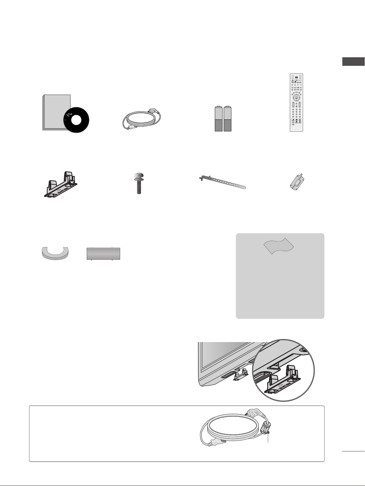
Ensure that the following accessories are included with your TV. If an accessory is missing, please contact the
dealer where you purchased the TV.
Owner's
Manual
Owner's manual
Owner’s Manual
Batteries
OK
INPUT MODE
TV
D/A
DVD
EXIT
VOL PR
GUIDE
BACK
MENU
RATIO
I/II
VCR
POWER
123
456
789
0
Q.VIEW
LIST
INDEX
SLEEP
HOLD
REVEAL
?
SUBTITLE
TEXT
INPUT
BRIGHT
MUTE
TV/RADIO
UPDATE
SIMPLINK
INFO i
FAV
TIME
Remote Control
Power Cord
Cable management clip
(50PG6**)
Cable Holder
(42PG6**)
Protection Cover
When installing the wall-mounted unit, use the protection
cover for desk-type stand installation.
NOT USING THE DESK-TYPE STAND
4-Bolts for stand assembly
(Refer to p.6)
(Only 42PG6**)
x 4
A
Image shown may differ from your TV.
Ferrite Core
(This feature is not
available for all models.)
Ferrite core can be used to reduce the electromagnetic
wave when connecting the power cord.
The closer the location of the ferrite core to the power
plug, the better it is.
Use of Ferrite Core (This feature is not available for all models.)
Install as close as possible to
the power plug.
Page 4

2
CONTENTS
CONTENTS
ACCESSORIES
. . . . . . . . . . . . . . . . . . . . . . . . . . . . . . . . . . . . . . . . . . . . .
1
PREPARATION
Front Panel Controls . . . . . . . . . . . . . . . . . . . . . . . . 4
Back Panel Information . . . . . . . . . . . . . . . . . . . . . . 5
Stand Installation . . . . . . . . . . . . . . . . . . . . . . . . . . . 6
Please set it up carefully so the product
does not fall over . . . . . . . . . . . . . . . . . . . . . . . . . . . 7
Back Cover for Wire Arrangement . . . . . . . . . . . . . . 8
Desktop Pedestal Installation . . . . . . . . . . . . . . . . . . 9
Wall Mount: Horizontal Installation . . . . . . . . . . . . . 9
Antenna Connection . . . . . . . . . . . . . . . . . . . . . . . . 10
EXTERNAL EQUIPMENT SETUP
HD Receiver Setup . . . . . . . . . . . . . . . . . . . . . . . . 11
DVD Setup . . . . . . . . . . . . . . . . . . . . . . . . . . . . . . . . 13
VCR Setup . . . . . . . . . . . . . . . . . . . . . . . . . . . . . . . . 16
Digital Audio Out Setup . . . . . . . . . . . . . . . . . . . . . 18
Other A/V Source Setup . . . . . . . . . . . . . . . . . . . . 19
PC Setup . . . . . . . . . . . . . . . . . . . . . . . . . . . . . . . . . 20
- Screen Setup for PC mode . . . . . . . . . . . . . . . 23
WATCHING TV / PROGRAMME CONTROL
Remote Control Key Functions . . . . . . . . . . . . . . . . 27
Turning on the TV . . . . . . . . . . . . . . . . . . . . . . . . . . 29
Programme Selection . . . . . . . . . . . . . . . . . . . . . . . 30
Volume Adjustment . . . . . . . . . . . . . . . . . . . . . . . . 30
On-Screen Menus Selection and Adjustment . . . . 31
Auto Programme Tuning (In Digital Mode) . . . . . . 32
Manual Programme Tuning (In Digital Mode) . . . . 33
Programme Edit (In Digital Mode) . . . . . . . . . . . . . 34
5V Antenna Power(In Digital Mode Only) . . . . . . .36
Booster (In Digital Mode Only) . . . . . . . . . . . . . . . 37
Software Update (In Digital Mode Only) . . . . . . . 38
Diagnostics (In Digital Mode Only) . . . . . . . . . . . . 39
Auto Programme Tuning (In Analogue Mode) . . . . . 40
Manual Programme Tuning (In Analogue Mode)
. . . . . . . 41
Fine Tuning (In Analogue Mode) . . . . . . . . . . . . . . 42
Assigning a Station Name (In Analogue Mode)
. . . . . . 42
Programme Edit (In Analogue Mode)
. . . . . . . . . . . . . 43
Selecting the Programme Table . . . . . . . . . . . . . . 45
Input Source Selection . . . . . . . . . . . . . . . . . . . . . 46
SIMPLINK Function . . . . . . . . . . . . . . . . . . . . . . . . 47
EPG (ELECTRONIC PROGRAMME GUIDE)
(IN DIGITAL MODE)
Switch On/Off EPG . . . . . . . . . . . . . . . . . . . . . . . . . 49
Select Programme . . . . . . . . . . . . . . . . . . . . . . . . . . 49
Button Function in NOW/NEXT Guide Mode . . . . . 50
Button Function in 8 Day Guide Mode . . . . . . . . . . 50
Button Function in Date Change Mode . . . . . . . . . . 50
Button Function in Extended Description Box . . . . . 51
Button Function in Remind Mode . . . . . . . . . . . . . . 51
Button Function in Schedule List Mode . . . . . . . . . . 51
PICTURE CONTROL
Picture Size (Aspect Ratio) Control . . . . . . . . . . . . . . . . . 52
Preset Picture Settings
- Picture Mode-Preset . . . . . . . . . . . . . . . . . . . . . . . . . . 54
-
Auto Colour Tone Control (Warm/Medium/Cool)
. . . .55
Manual Picture Adjustment
- Picture Mode-User Option . . . . . . . . . . . . . . . . . . . . 56
- Colour Tone - User Option . . . . . . . . . . . . . . . . . . . . .57
XD - Picture Improvement Technology . . . . . . . . . . . . . . 58
XD Demo . . . . . . . . . . . . . . . . . . . . . . . . . . . . . . . . . . . . . . 59
Advanced - Cinema . . . . . . . . . . . . . . . . . . . . . . . . . . . . . . 60
Advanced - Black(Darkness) Level . . . . . . . . . . . . . . . . . . 61
Picture Reset . . . . . . . . . . . . . . . . . . . . . . . . . . . . . . . . . . . . 62
Image Sticking Minimization(ISM) Method . . . . . . . . . . . 63
Low-Power Picture Mode . . . . . . . . . . . . . . . . . . . . . . . . . . 64
Page 5

3
CONTENTS
SOUND & LANGUAGE CONTROL
Auto Volume Leveler . . . . . . . . . . . . . . . . . . . . . . . . 65
Preset Sound Settings - Sound Mode . . . . . . . . . . 66
Sound Setting Adjustment - User Mode . . . . . . . . . . 67
Balance . . . . . . . . . . . . . . . . . . . . . . . . . . . . . . . . . . . 68
TV Speakers On/Off Setup . . . . . . . . . . . . . . . . . . 69
Selecting Digital Audio . . . . . . . . . . . . . . . . . . . . . . 70
I/II
-
Stereo/Dual Reception (In Analogue Mode Only)
. 71
-
NICAM Reception (In Analogue Mode Only) . . . . . . .
72
- Speaker Sound Output Selection . . . . . . . . . . 72
Language Selection
(In Digital Mode Only) . . . . . .73
TIME SETTING
Clock Setup . . . . . . . . . . . . . . . . . . . . . . . . . . . . . 74
Auto On/Off Timer Setting . . . . . . . . . . . . . . . . . 75
Auto Shut-Off Setting . . . . . . . . . . . . . . . . . . . . . 76
Time Zone Setup . . . . . . . . . . . . . . . . . . . . . . . . . 77
Sleep Timer Setting . . . . . . . . . . . . . . . . . . . . . . . 77
PARENTAL CONTROL / RATINGS
Set Password & Lock System . . . . . . . . . . . . . . . . . 78
Parental Control . . . . . . . . . . . . . . . . . . . . . . . . . . . 79
TELETEXT
Switch On/Off . . . . . . . . . . . . . . . . . . . . . . . . . . . . . 80
SIMPLE Text . . . . . . . . . . . . . . . . . . . . . . . . . . . . . . . 80
TOP Text . . . . . . . . . . . . . . . . . . . . . . . . . . . . . . . . . 80
FASTEXT . . . . . . . . . . . . . . . . . . . . . . . . . . . . . . . . . 81
Special Teletext Functions . . . . . . . . . . . . . . . . . . . . 81
APPENDIX
Troubleshooting . . . . . . . . . . . . . . . . . . . . . . . . . . 82
Maintenance . . . . . . . . . . . . . . . . . . . . . . . . . . . . 84
Product Specifications . . . . . . . . . . . . . . . . . . . . . 85
Programming the Remote Control . . . . . . . . . . . . 86
Programming Code . . . . . . . . . . . . . . . . . . . . . . . 86
IR Codes . . . . . . . . . . . . . . . . . . . . . . . . . . . . . . . 88
External Control Device Setup . . . . . . . . . . . . . . 90
Page 6
4
PREPARATION
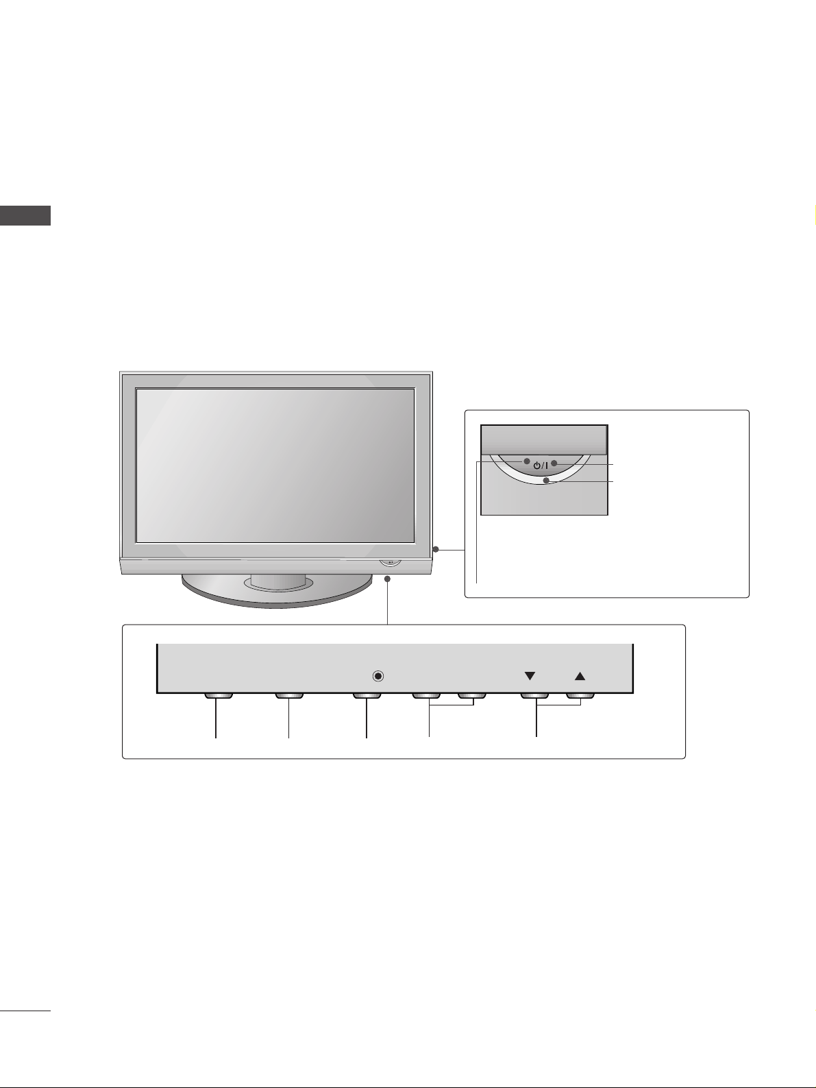
FRONT PANEL CONTROLS
PREPARATION
A
Image shown may differ from your TV.
A
If your TV has a protection film attached, remove the film and then wipe the TV with a polishing cloth.
PROGRAMMEVOLUMEMENU OKINPUT
Remote Control Sensor
POWER
Power/Standby Indicator
• illuminates red in standby mode.
• illuminates green when the TV is
switched on.
VOL
OK
MENU
INPUT
INPUT
MENU
OK
- +
VOL
PR
Page 7
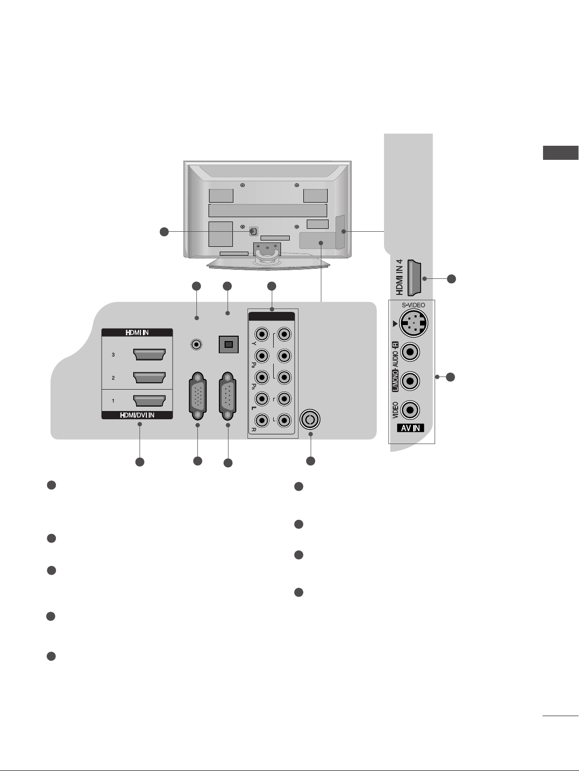
Power Cord Socket
This TV operates on an AC power. The voltage is
indicated on the Specifications page. Never
attempt to operate the TV on DC power.
AUDIO IN (RGB/DVI)
Connect the audio from a PC.
OPTICAL DIGITAL AUDIO OUT
Connect digital audio from various types of equipment.
Note: In standby mode, these ports do not work.
Component Input
Connect a component video/audio device to
these jacks.
HDMI IN 1/2/3/4
Connect a HDMI signal to HDMI IN or DVI (VIDEO)
signal to HDMI/DVI port with DVI to HDMI cable.
RGB IN (PC)
Connect the output from a PC.
RS-232C IN (CONTROL & SERVICE) PORT
Connect to the RS-232C port on a PC.
Antenna Input
Connect RF antenna to this jack.
AV (Audio/Video) IN
Connect audio/video output from an external
device to these jacks.
S-VIDEO
Connect S-Video out from an S-VIDEO device.
5
BACK PANEL INFORMATION
A
Image shown may differ from your TV.
1
2
3
4
5
7
6
8
9
1
5
2 43
8
7
6
5
PREPARATION
9
OPTICAL
DIGITAL
AUDIO OUT
(CONTROL & SERVICE)
AUDIO IN
(RGB/DVI)
RGB IN
(PC)
COMPONENT IN
1 2
VIDEO
RS-232C IN
AUDIO
ANTENNA IN
Page 8
6
PREPARATION
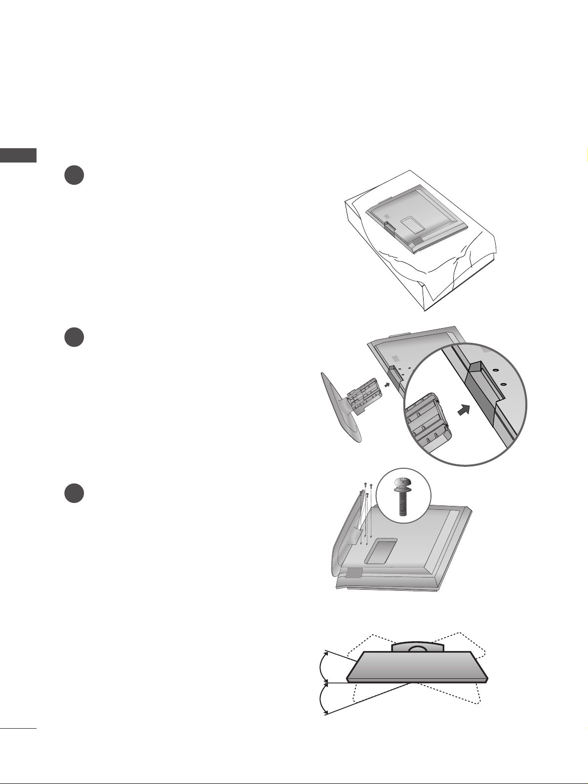
STAND INSTALLATION
(only 42PG6**)
1
2
3
Carefully place the TV screen side down on a
cushioned surface to protect the screen from
damage.
Assemble the TV as shown.
Fix the 4 bolts securely using the holes in the
back of the TV.
Swivel Stand
After installing the TV, you can adjust the TV set
manually to the left or right direction by 20 degrees
to suit your viewing position.
PREPARATION
A
When assembling the desk type stand, check whether the bolt is fully tightened. (If not tightened fully, the
product can tilt forward after the product installation.) If you tighten the bolt with excessive force, the bolt
can deviate from abrasion of the tightening part of the bolt.
Page 9
7
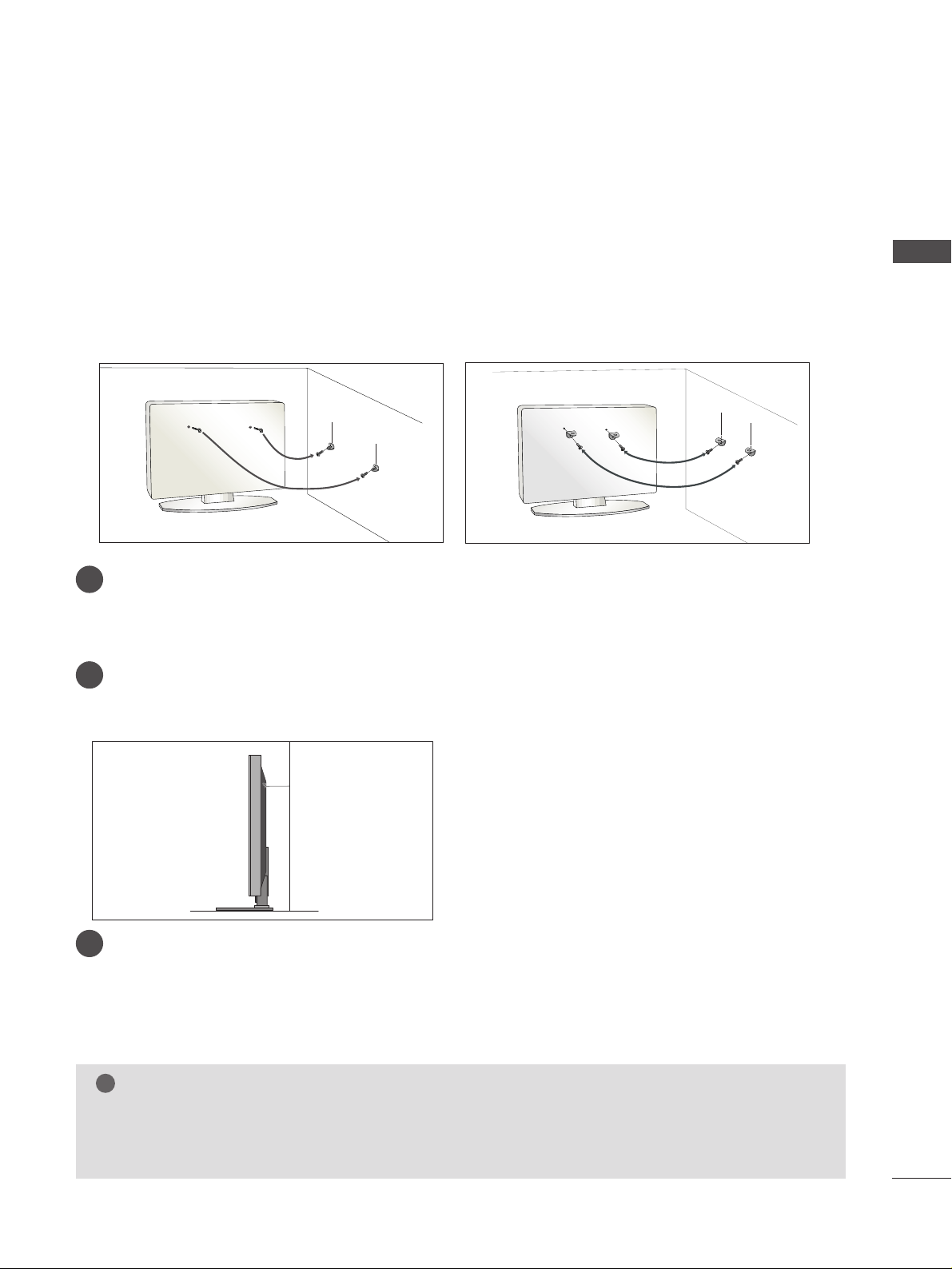
PLEASE SET IT UP CAREFULLY SO THE PRODUCT DOES NOT FALL OVER.
■
You should purchase necessary components to fix the TV to the wall on the market.
■
Position the TV close to the wall to avoid the possibility of it falling when pushed.
■
The instructions shown below are a safer way to set up the TV, which is to fix it to the wall, avoiding the possibility of it falling forwards if pulled. This will prevent the TV from falling forward and causing injury. This will
also prevent the TV from damage. Ensure that children do not climb or hang from the TV.
NOTE
!
G
When moving the TV undo the cords first.
G
Use a platform or cabinet strong and large enough to support the size and weight of the TV.
G
To use the TV safely make sure that the height of the bracket on the wall and on the TV is the same.
3
1
2
Use the eye-bolts or TV brackets/bolts to fix the TV to the wall as shown in the picture.
(If your TV has bolts in the eyebolts, loosen these bolts.)
* Insert the eye-bolts or TV brackets/bolts and tighten them securely in the upper holes.
Secure the wall brackets with the bolts on the wall. Match the height of the bracket that is mounted
on the wall.
3
Use a sturdy rope to tie the TV. It is safer to tie the rope so it becomes horizontal between the wall
and the TV.
2
1
2
1
PREPARATION
Page 10
8
PREPARATION
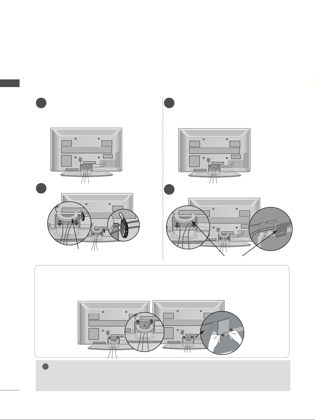
BACK COVER FOR WIRE ARRANGEMENT
Connect the cables as necessary.
To connect additional equipment, see the
EExx tteerrnnaa ll eeqquuii ppmmee nntt SSeettuupp
section.
1
Install the
CCAABBLLEE MMAANNAAGGEEMMEENNTT CCLLIIPP
as shown.
2
Hold the
CC AABBLLEE MMAANNAA GGEEMMEENNTT CCLLIIPP
with both hands and pull it upward.
NOTE
!
GG
Do not use the CABLE MANAGEMENT CLIP to lift the TV.
- If the TV is dropped, you may be injured or the TV may be damaged.
HHooww ttoo rreemmoovvee tthhee ccaabbllee mmaannaaggeemmeenntt cclliipp
■
Image shown may differ from your TV.
CABLE MANAGEMENT CLIP
Connect the cables as necessary.
To connect additional equipment, see the
EExx tteerrnnaa ll ee qquuii pp mm eenntt SSeettuupp
section.
1
Install the
CC AABBLLEE MMAA NNAAGGEEMMEENN TT CCLLIIPP
as shown.
2
CABLE MANAGEMENT CLIP
42PG6
**
50PG6
**
50PG6
**
42PG6
**
Separate CABLE
MANAGEMENT from
TV by pressing two
latches.
Fix the
CC aabbllee HHoollddee rr
as
shown and bundle the
cables.
For the 42PG6**
model, press the
center of the
CABLE MANAGEMENT CLIP and
then lift up it.
PREPARATION
Page 11
9
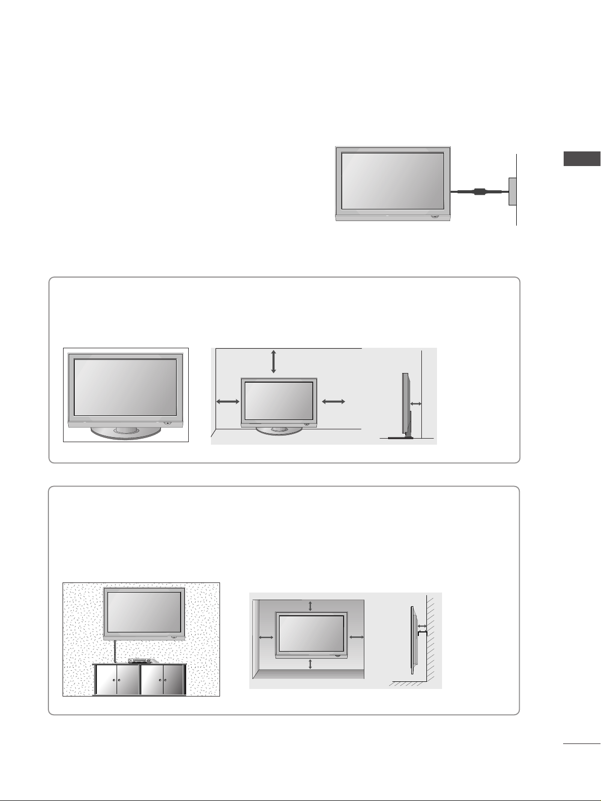
DESKTOP PEDESTAL INSTALLATION
For adequate ventilation allow a clearance of 4” (10cm) all around the TV.
EARTHING
Ensure that you connect the earth wire to prevent possible
electric shock. Do not try to earth the TV by connecting it
to telephone wires, lightening rods or gas pipes.
Power Supply
Circuit
breaker
■
The TV can be installed in various ways such as on a wall or on a desktop etc.
■
The TV is designed to be mounted horizontally.
4 inches
4 inches 4 inches 4 inches
WALL MOUNT: HORIZONTAL INSTALLATION
For adequate ventilation allow a clearance of 4” (10cm) all around the TV. We recommend that you use
a wall mounting bracket of LG brand when mounting the TV to a wall.
4 inches
4 inches
4 inches 4 inches
4 inches
PREPARATION
Page 12
ANTENNA IN
10
PREPARATION
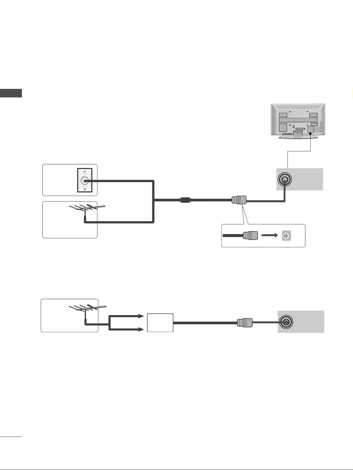
ANTENNA IN
■
For optimum picture quality, adjust antenna direction.
■
An antenna cable and converter are not supplied.
■
To prevent damage do not connect to the mains outlet until all connections are made between the devices.
Multi-family Dwellings/Apartments
(Connect to wall antenna socket)
Single-family Dwellings /Houses
(Connect to wall jack for outdoor antenna)
Outdoor
Antenna
(VHF, UHF)
Wall
Antenna
Socket
RF Coaxial Wire (75 ohm)
ANTENNA CONNECTION
Antenna
UHF
Signal
Amplifier
VHF
■
In poor signal areas, to achieve better picture quality it may be necessary to install a signal amplifier to the
antenna as shown above.
■
If signal needs to be split for two TVs,use an antenna signal splitter for connection.
- 5V antenna power works In Digital
mode only. (Refer to p. 36)
PREPARATION
Page 13
11
EXTERNAL EQUIPMENT SETUP
HD RECEIVER SETUP
■
This TV can receive Digital RF/Cable signals without an external digital set-top box. However, if you do receive
Digital signals from a digital set-top box or other digital external device, refer to the diagram as shown below.
VIDEO
12
AUDIO
COMPONENT IN
RGB IN
(PC)
RS-232C IN
(CONTROL & SERVICE)
OPTICAL
DIGITAL
AUDIO OUT
AUDIO IN
(RGB/DVI)
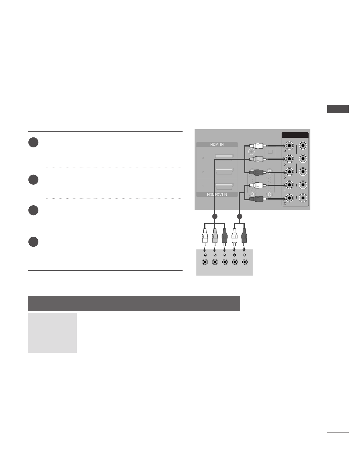
Connecting with a component cable
Connect the video outputs (Y, P
B, PR
)
of the digital set
top box to the
CC OOMMPPOO NNEENNTT IINN11 VVIIDDEEOO
jacks on
the TV.
Connect the audio output of the digital set-top box to
the
CC OOMMPPOO NNEENNTT IINN11 AA UUDD IIOO
jacks on the TV.
Turn on the digital set-top box.
(
Refer to the owner’s manual for the digital set-top box.
)
Select Component1 input source using the
II NNPPUU TT
button on the remote control.
If connected to
CC OOMMPPOO NNEENNTT II NN22
, select
Component2 input source.
2
3
4
1
Signal
480i/576i
480p/576p
720p/1080i
10 8 0 p
Component
Yes
Yes
Yes
No
HDMI1/2/3/4
No
Yes
Yes
Yes
1 2
■
To avoid damaging any equipment, never plug in any power cords until you have finished connecting all equipment.
EXTERNAL EQUIPMENT SETUP
Page 14
12
EXTERNAL EQUIPMENT SETUP
RGB IN
(PC)
RS-232C IN
(CONTROL & SERVICE)
DIGITAL
AUDIO OUT
(RGB/DVI)
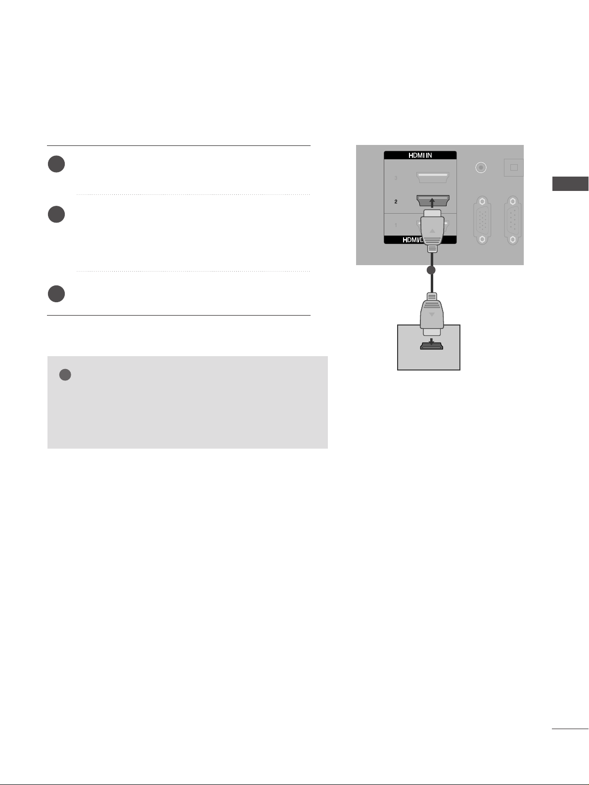
HDMI-DTV OUTPUT
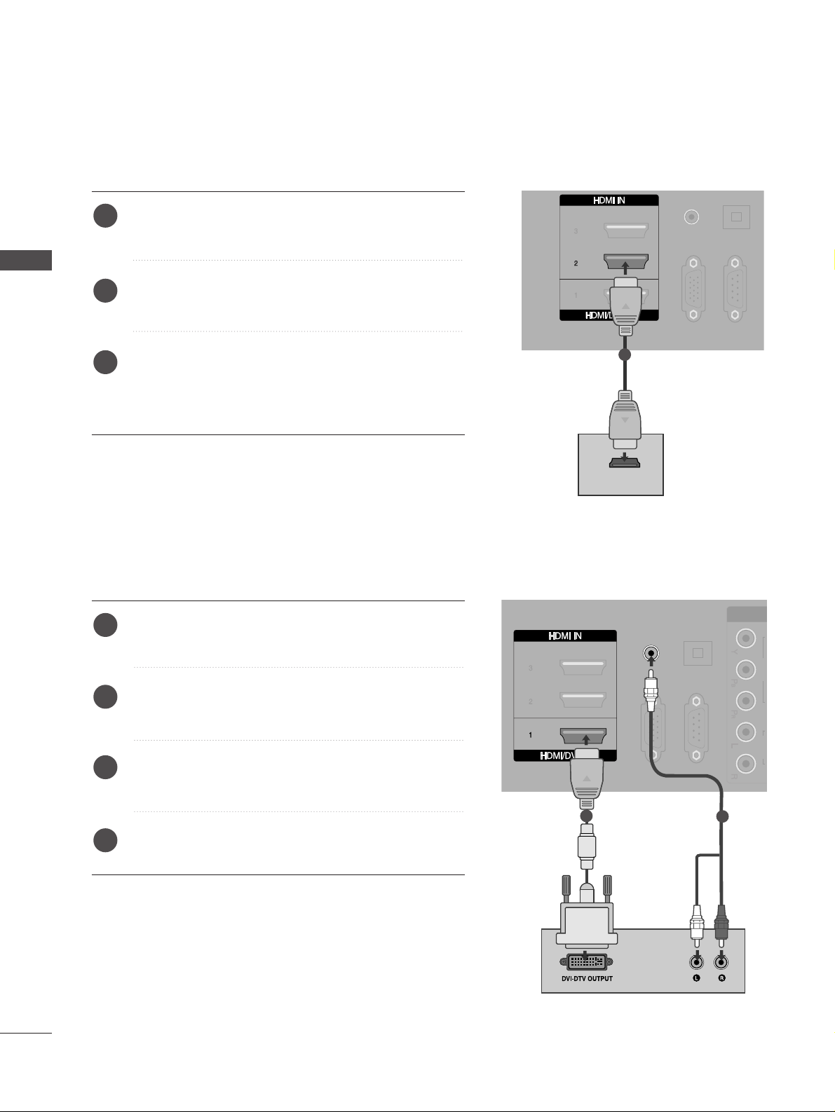
Connecting a set-top box with an HDMI cable
Connect the digital set-top box to
HHDDMMII IINN 22
jack on
the TV.
Turn on the digital set-top box.
(
Refer to the owner’s manual for the digital set-top box.
)
Select HDMI2 input source using the
II NNPPUU TT
button
on the remote control.
If connected to
HHDDMMII II NN 33
(or
HHDDMMII II NN 44
) jack,
select HDMI3 (or HDMI4) input source.
2
3
1
AUDIO IN
(RGB/DVI)
VIDEO AUDIO
COMPONE
RGB IN
(PC)
RS-232C IN
(CONTROL & SERVICE)
OPTICAL
DIGITAL
AUDIO OUT
1
1
2
Connect the digital set-top box to
HHDDMMII//DDVVII II NN 11
jack on the TV.
Connect the audio output of the digital set-top box to
the
AAUU DDIIOO II NN ((RRGG BB// DDVVII))
jack on the TV.
Turn on the digital set-top box. (Refer to the owner’s
manual for the digital set-top box.
)
Select HDMI1 input source using the
II NNPPUU TT
button
on the remote control.
2
3
4
1
Connecting with a HDMI to DVI cable
EXTERNAL EQUIPMENT SETUP
Page 15
13
DVD SETUP
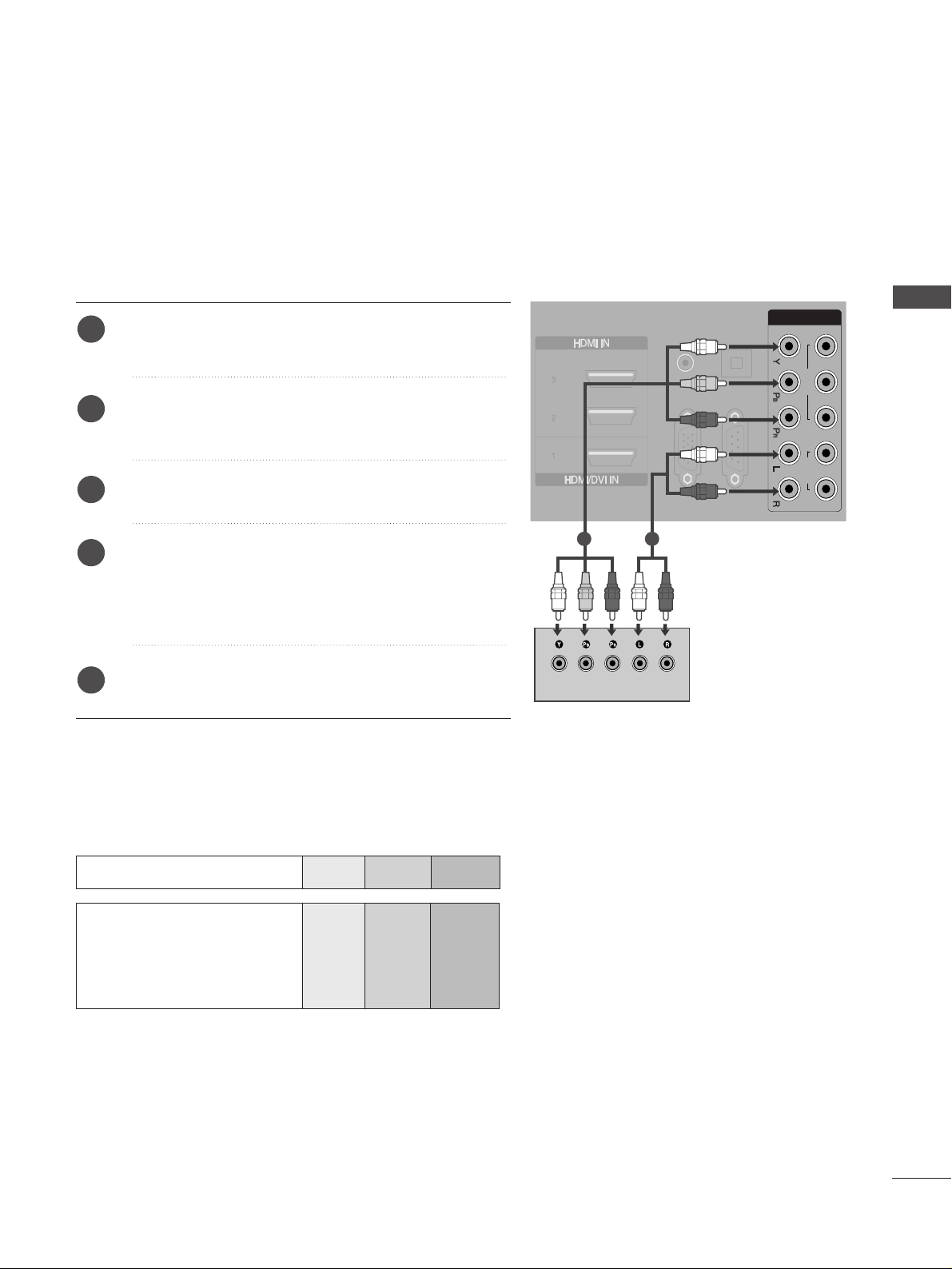
Connecting with a component cable
Component Input ports
To achieve better picture quality, connect a DVD player to the component input ports as shown below.
Component ports on the TV
YPBP
R
Video output ports
on DVD player
Y
Y
Y
Y
P
B
B-Y
Cb
Pb
P
R
R-Y
Cr
Pr
Connect the video outputs (Y, PB, PR
)
of the DVD to the
CC OOMMPPOO NNEENNTT II NN11 VVIIDD EEOO
jacks on the TV.
Connect the audio outputs of the DVD to the
CC OOMMPPOO NNEENNTT IINN11 AA UUDD IIOO
jacks on the TV.
Turn on the DVD player, insert a DVD.
Select Component1 input source using the
II NNPPUU TT
button on the remote control.
If connected to
CC OOMMPPOO NNEENNTT II NN22
, select
Component2 input source.
Refer to the DVD player's manual for operating
instructions.
2
3
4
5
1
VIDEO
12
AUDIO
COMPONENT IN
RGB IN
(PC)
RS-232C IN
(CONTROL & SERVICE)
OPTICAL
DIGITAL
AUDIO OUT
AUDIO IN
(RGB/DVI)
1 2
EXTERNAL EQUIPMENT SETUP
Page 16
14
EXTERNAL EQUIPMENT SETUP
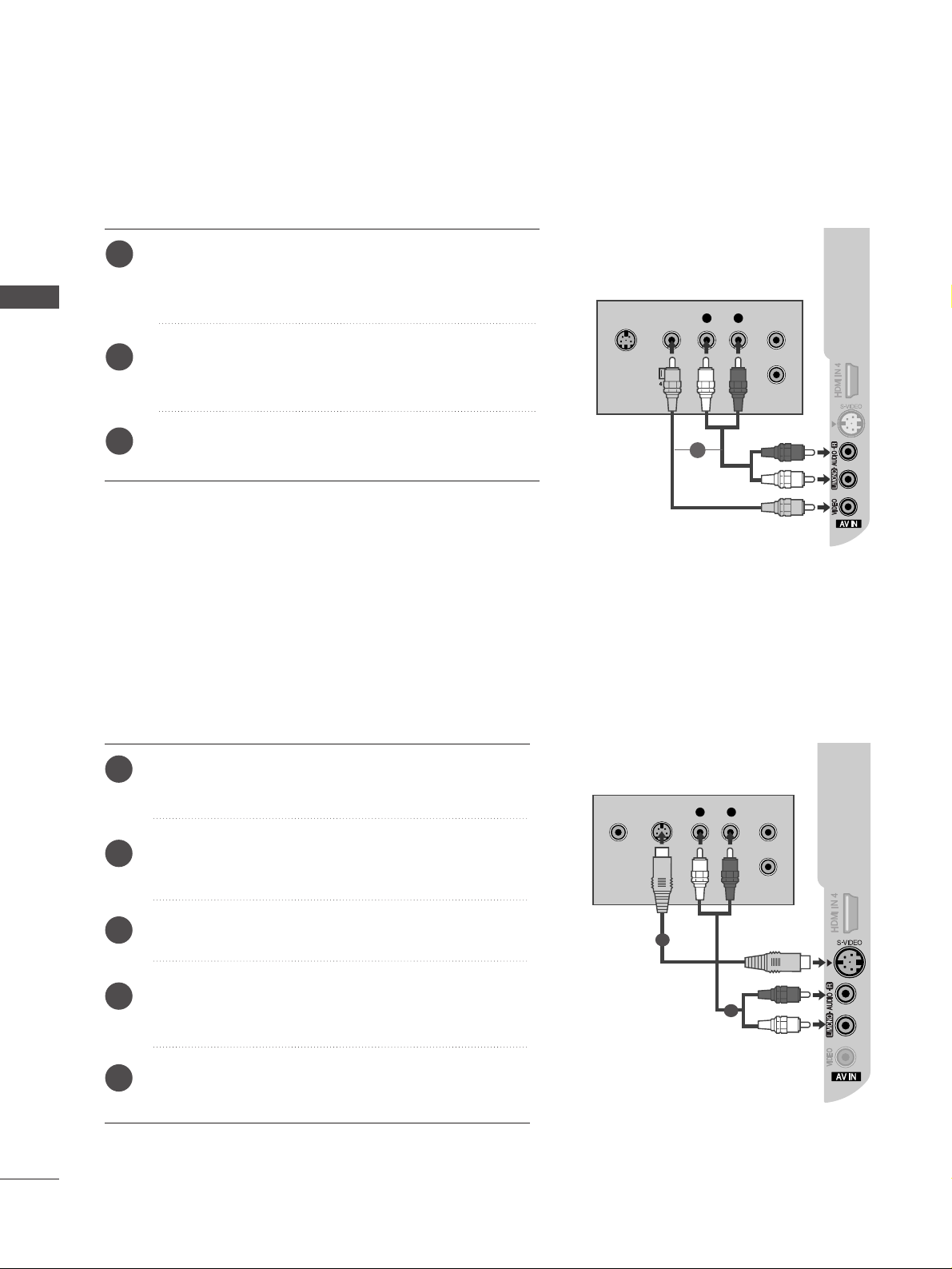
Connecting with a S-Video cable
L R
S-VIDEOVIDEO
OUTPUT
SWITCH
ANT IN
ANT OUT
Connect the S-VIDEO output of the DVD to the
SS--
VVIIDDEEOO
input on the TV.
Connect the audio outputs of the DVD to the
AAUU DDIIOO
input jacks on the TV.
Turn on the DVD player, insert a DVD.
Select AV input source using the INPUT button on
the remote control.
Refer to the DVD player's manual for operating
instructions.
2
3
4
5
1
1
2
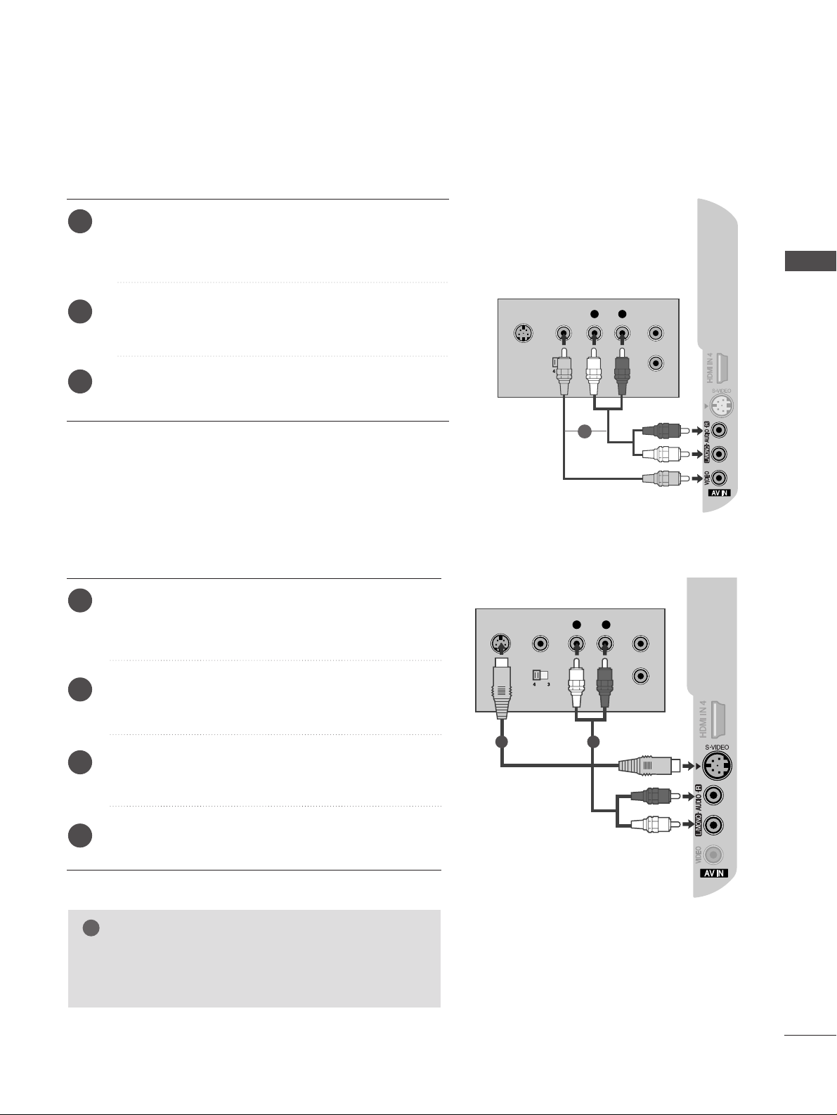
Connecting with a RCA cable
Connect the
AAUU DDIIOO/VVIIDDEEOO
jacks between TV and
DVD player. Match the jack colours (Video = yellow, Audio
Left = white, and Audio Right = red)
Insert a DVD into the DVD player and press PLAY on the
DVD player. (Refer to the DVD player owner’s manual.
)
Select
AV input source using the
II NNPPUU TT
button on the
remote control.
2
3
1
L
R
S-VIDEO
VIDEO
OUTPUT
SWITCH
ANT IN
ANT OUT
EXTERNAL EQUIPMENT SETUP
1
Page 17
15
AUDIO IN
(RGB/DVI)
RGB IN
(PC)
(CONTROL & SERVICE)
DIGITAL
AUDIO OUT
HDMI-DVD OUTPUT
Connecting HDMI cable
Connect the HDMI output of the DVD to the
HHDDMMII
II NN 22
jack on the set.
Select HDMI2 input source using the
II NNPPUU TT
button
on the remote control.
If connected to
HHDDMMII II NN 33
(or
HHDDMMII II NN 44
) jack,
select HDMI3 (or HDMI4) input source.
Refer to the DVD player's manual for operating
instructions.
1
2
3
GG
The TV can receive video and audio signals simultaneously
when using a HDMI cable.
GG
If the DVD does not support Auto HDMI, you must set the
output resolution appropriately.
NOTE
!
1
EXTERNAL EQUIPMENT SETUP
Page 18
16
EXTERNAL EQUIPMENT SETUP
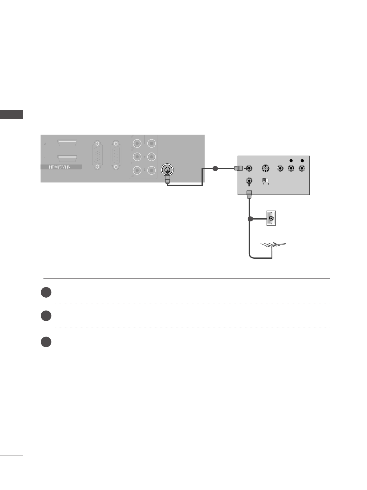
When connecting with a RF Cable
■
To avoid picture noise (interference), allow adequate distance between the VCR and TV.
■
If 4:3 picture format is used for an extended period the fixed images on the sides of the screen may remain
visible.
ANTENNA IN
AUDIO
RGB IN
(PC)
RS-232C IN
(CONTROL & SERVICE)
OUTPUT
SWITCH
ANT IN
R
S-VIDEO VIDEO
ANT OUT
L
Wall Jack
Antenna
Connect the
AANNTT OOUU TT
socket of the VCR to the
AANNTTEENN NNAA II NN
socket on the TV.
Connect the antenna cable to the
AANN TT IINN
socket of the VCR.
Press the PLAY button on the VCR and match the appropriate channel between the TV and VCR for
viewing.
VCR SETUP
1
2
2
3
1
EXTERNAL EQUIPMENT SETUP
Page 19
17
L R
S-VIDEO VIDEO
OUTPUT
SWITCH
ANT IN
ANT OUT
Connecting with a RCA cable
Connect the
AAUU DDIIOO/VVIIDDEEOO
jacks between TV and
VCR. Match the jack colours (Video = yellow, Audio Left =
white, and Audio Right = red)
Insert a video tape into the VCR and press PLAY on the
VCR. (Refer to the VCR owner’s manual.
)
Select
AV input source using the
II NNPPUU TT
button on the
remote control.
2
3
1
GG
If both S-VIDEO and VIDEO sockets have been
connected to the S-VHS VCR simultaneously, only
the S-VIDEO can be received.
NOTE
!
S-VIDEO
L R
VIDEO
OUTPUT
SWITCH
ANT IN
ANT OUT
Connecting with a S-Video cable
Connect the S-VIDEO output of the VCR to the
SS --
VVIIDDEEOO
input on the TV. The picture quality is improved;
compared to normal composite (RCA cable) input.
Connect the audio outputs of the VCR to the
AAUU DDIIOO
input jacks on the TV.
Insert a video tape into the VCR and press PLAY on the
VCR. (Refer to the VCR owner’s manual.)
Select AV input source using the
IINNPPUUTT
button on the
remote control.
2
3
4
1
1 2
EXTERNAL EQUIPMENT SETUP
1
Page 20
18
EXTERNAL EQUIPMENT SETUP
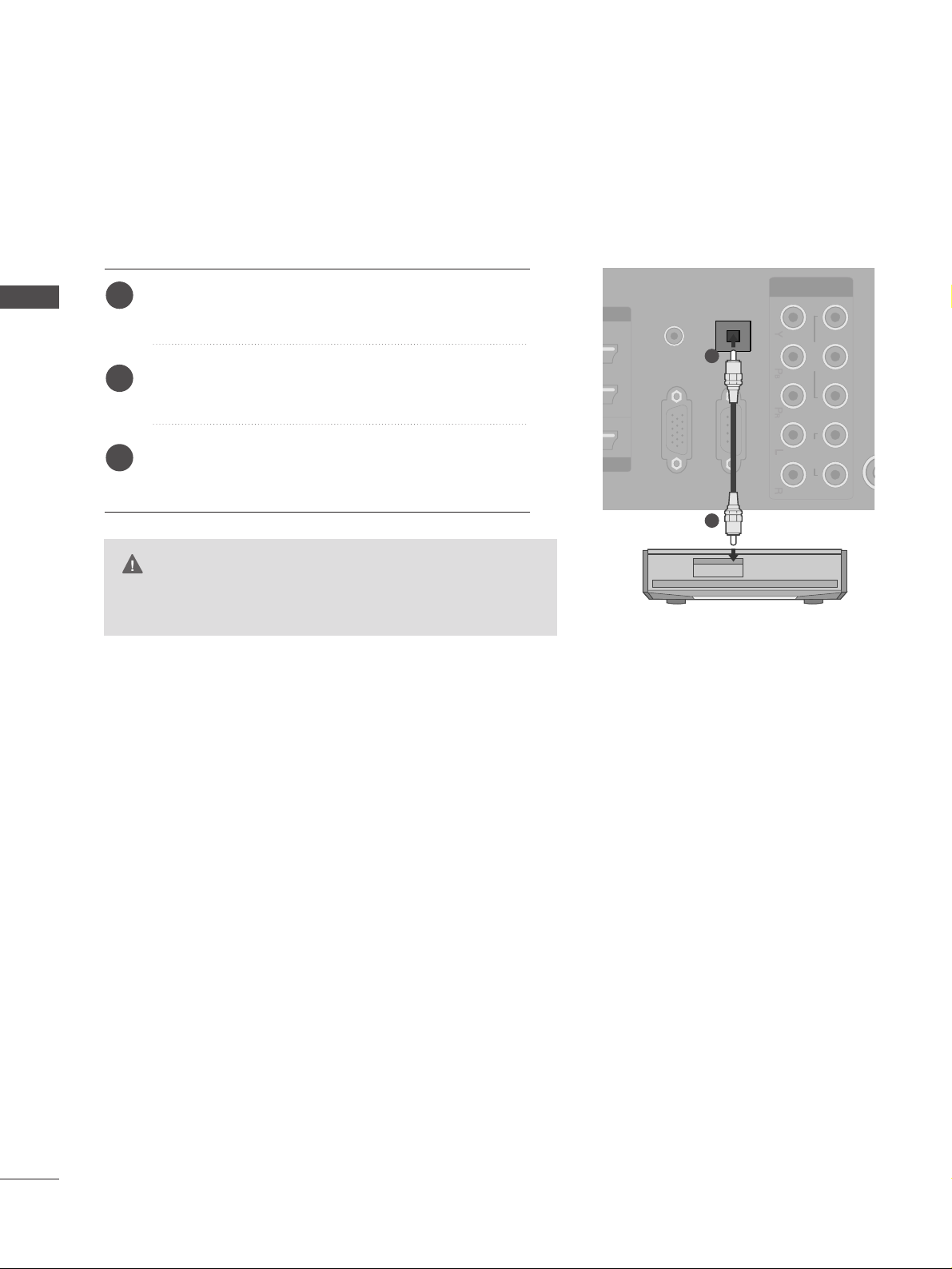
DIGITAL AUDIO OUT SETUP
- Sending the TV’s audio signal to external audio equipment via
the Digital Audio Output (Optical) port.
G
Do not look into the optical output port. Looking at the
laser beam may damage your vision.
CAUTION
OPTICAL
DIGITAL
AUDIO OUT
VIDEO AUDIO
COMPONENT IN
RGB IN
(PC)
RS-232C IN
(CONTROL & SERVICE)
AUDIO IN
(RGB/DVI)
Connect one end of an optical cable to the TV Digital
Audio (Optical)Output port.
Connect the other end of the optical cable to the
digital audio (optical)input on the audio equipment.
Set the “TV Speaker option - Off ” in the AUDIO
menu.(
G
pp..6699
). Refer to the external audio equipment
instruction manual for operation.
2
3
1
1
2
EXTERNAL EQUIPMENT SETUP
Page 21
19
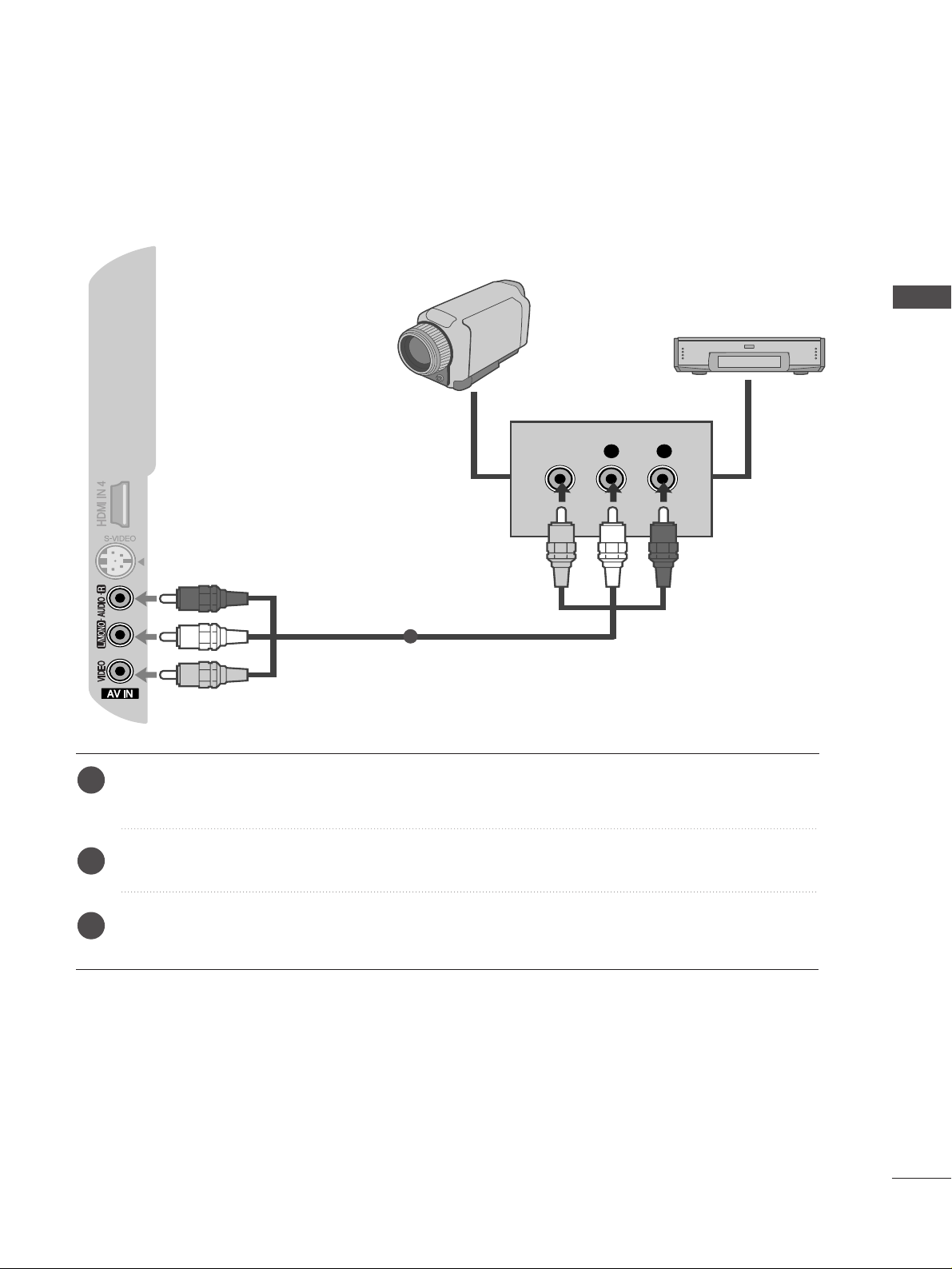
OTHER A/V SOURCE SETUP
Connect the
AAUU DDIIOO/VVIIDDEEOO
jacks between TV and external equipment. Match the jack colors
.
(
Video = yellow, Audio Left = white, and Audio Right = red
)
Select AV input source using the
II NNPPUU TT
button on the remote control.
Operate the corresponding external equipment.
Refer to external equipment operating guide.
L R
VIDEO
Camcorder
Video Game Set
1
1
2
3
EXTERNAL EQUIPMENT SETUP
Page 22
20
EXTERNAL EQUIPMENT SETUP
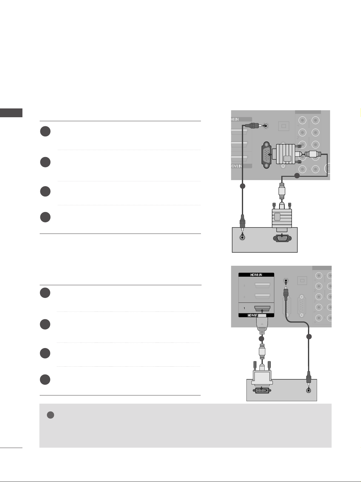
PC SETUP
This TV provides Plug and Play capability, meaning that the PC adjusts automatically to the TV's settings.
Connecting with a D-sub 15 pin cable
RGB IN
(PC)
AUDIO IN
(RGB/DVI)
VIDEO AUDIO
COMPONENT IN
RS-232C IN
(CONTROL & SERVICE)
OPTICAL
DIGITAL
AUDIO OUT
RGB OUTPUT
AUDIO
Connect the RGB output of the PC to the RGB IN
(PC) jack on the TV.
Connect the PC audio output to the AUDIO IN
(RGB/DVI) jack on the TV.
Turn on the PC and the TV.
Select RGB input source using the INPUT button on
the remote control.
2
3
4
1
Connecting with a HDMI to DVI cable
GG
If the PC has a DVI output and no HDMI output, a separated audio connection is necessary.
GG
If the PC does not support Auto DVI, you need to set the output resolution appropriately.
NOTE
!
AUDIO IN
(RGB/DVI)
VIDEO AUDIO
COMPONENT IN
RGB IN
(PC)
RS-232C IN
(CONTROL & SERVICE)
OPTICAL
DIGITAL
AUDIO OUT
AUDIO
DVI-PC OUTPUT
Connect the DVI output of the PC to the
HHDDMMII//DDVVII
II NN 11
jack on the TV.
Connect the PC audio output to the
AAUU DDIIOO IINN
((RR GGBB //DDVVII))
jack on the TV.
Turn on the PC and the TV.
Select HDMI1 input source using the INPUT button
on the remote control.
2
3
4
1
2
1
1
2
EXTERNAL EQUIPMENT SETUP
Page 23

21
NOTE
!
G
To enjoy vivid picture and sound, connect a PC to
the TV.
G
Avoid keeping a fixed image on the TV’s screen for
prolonged periods of time. The fixed image may
become permanently imprinted on the screen; use
a screen saver when possible.
G
Connect the PC to the RGB (PC) or HDMI IN (or
HDMI/DVI IN) port of the TV; change the resolution.
G
There may be interference relating to resolution,
vertical pattern, contrast or brightness in PC
mode. Change the PC mode to another resolution
or change the refresh rate to another rate or
adjust the brightness and contrast on the menu
until the picture is clear. If the refresh rate of the
PC graphic card can not be changed, change the
PC graphic card or consult the manufacturer of
the PC graphic card.
G
The synchronization input waveform for
Horizontal and Vertical frequencies are separate.
G
We recommend using 1024x768, 60Hz for the
PC mode, these should provide the best picture
quality.
G
Connect the signal cable from the monitor output
port of the PC to the RGB (PC) port of the TV or
the signal cable from the HDMI output port of
the PC to the HDMI IN (or HDMI/DVI IN) port
on the TV.
G
Connect the audio cable from the PC to the
Audio input on the TV. (Audio cables are not
included with the TV).
G
If using a sound card, adjust PC sound as
required.
G
This TV uses a VESA Plug and Play Solution. The
TV provides EDID data to the PC system with a
DDC protocol. The PC adjusts automatically when
using this TV.
G
DDC protocol is preset for RGB (Analog RGB),
HDMI (Digital RGB) mode.
G
If required, adjust the settings for Plug and Play
functionality.
G
If the graphic card on the PC does not output
analogue and digital RGB simultaneously, connect
only one of either RGB or HDMI IN (or HDMI/DVI
IN) to display the PC output on the TV.
G
If the graphic card on the PC does output analogue and digital RGB simultaneously, switch the
TV to either RGB or HDMI; (the other mode is set
to Plug and Play automatically by the TV.)
G
DOS mode may not work depending on the video
card if you use a HDMI to DVI cable.
G
If you use too long an RGB[PC] cable, there may
be interference on the screen. We recommend
using under 5m of cable. This provides the best
picture quality.
EXTERNAL EQUIPMENT SETUP
Page 24

22
EXTERNAL EQUIPMENT SETUP
Supported Display Resolution
Resolution
720x400
640x480
Horizontal
Frequency(kHz)
Vertical
Frequency(Hz)
800x600
832x624
1024x768
1280x768
1360x768
RGB[PC] / HDMI[PC] mode
640x480
720x480
720x576
1280x720
1920x1080
31.469
31.469
31.47
31.50
31.25
37. 50
44.96
45.00
33.72
33.75
28.125
27.00
56.25
67. 433
67. 500
HDMI[DTV] mode
Resolution
Horizontal
Frequency(kHz)
Vertical
Frequency(Hz)
31.468
31.469
37. 500
37. 879
46.875
49.725
48.363
56.476
60.023
47. 693
47. 649
70.08
59.94
75.00
60.31
75.00
74.55
60.00
70.00
75.03
59.99
59.94
59.94
60.00
59.94
60.00
50.00
50.00
59.94
60.00
59.94
60.00
50.00
24.00
50.00
59.94
60.00
EXTERNAL EQUIPMENT SETUP
Page 25
23
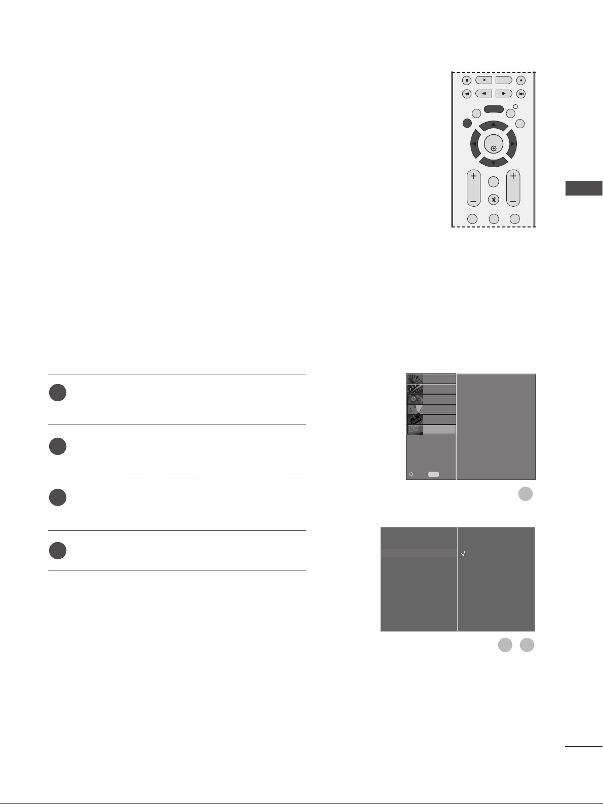
Screen Setup for PC mode
Automatically adjusts picture position and minimizes image
instability. After adjustment, if the image is still not correct, your
TV is functioning properly but needs further adjustment.
Auto configure
This function is for automatic adjustment of the screen position,
clock, and phase. The displayed image will be unstable for a few
seconds while the auto configuration is in progress.
Press the MENU button and then
D
or
E
button to
select the SCREEN menu.
Press the
G
button and then
D
or
E
button to select
Auto Config..
Press the
G
button to start Auto Config..
• When Auto Config. has finished, OK will be shown
on screen.
• If the position of the image is still not correct, try
Auto adjustment again.
• If picture needs to be adjusted again after Auto
adjustment in RGB (PC), you can adjust the
Manual Config..
Press the EXIT button to return to normal TV viewing.
Auto Configure (RGB [PC] mode only)
Auto Config. G
Manual Config.
XGA Mode
Aspect Ratio
Reset
To Set
1
3
2
1
2
3
4
Auto Config.
Manual Config.
XGA Mode
Aspect Ratio
Reset
SETUP
O
PICTURE
O
Prev.
MENU
Move
AUDIO
O
TIME
O
OPTION
O
SCREEN G
EXTERNAL EQUIPMENT SETUP
EXIT
BACK
MENU
INFO i
GUIDE
VOL PR
123
OK
FAV
MUTE
Page 26
24
EXTERNAL EQUIPMENT SETUP
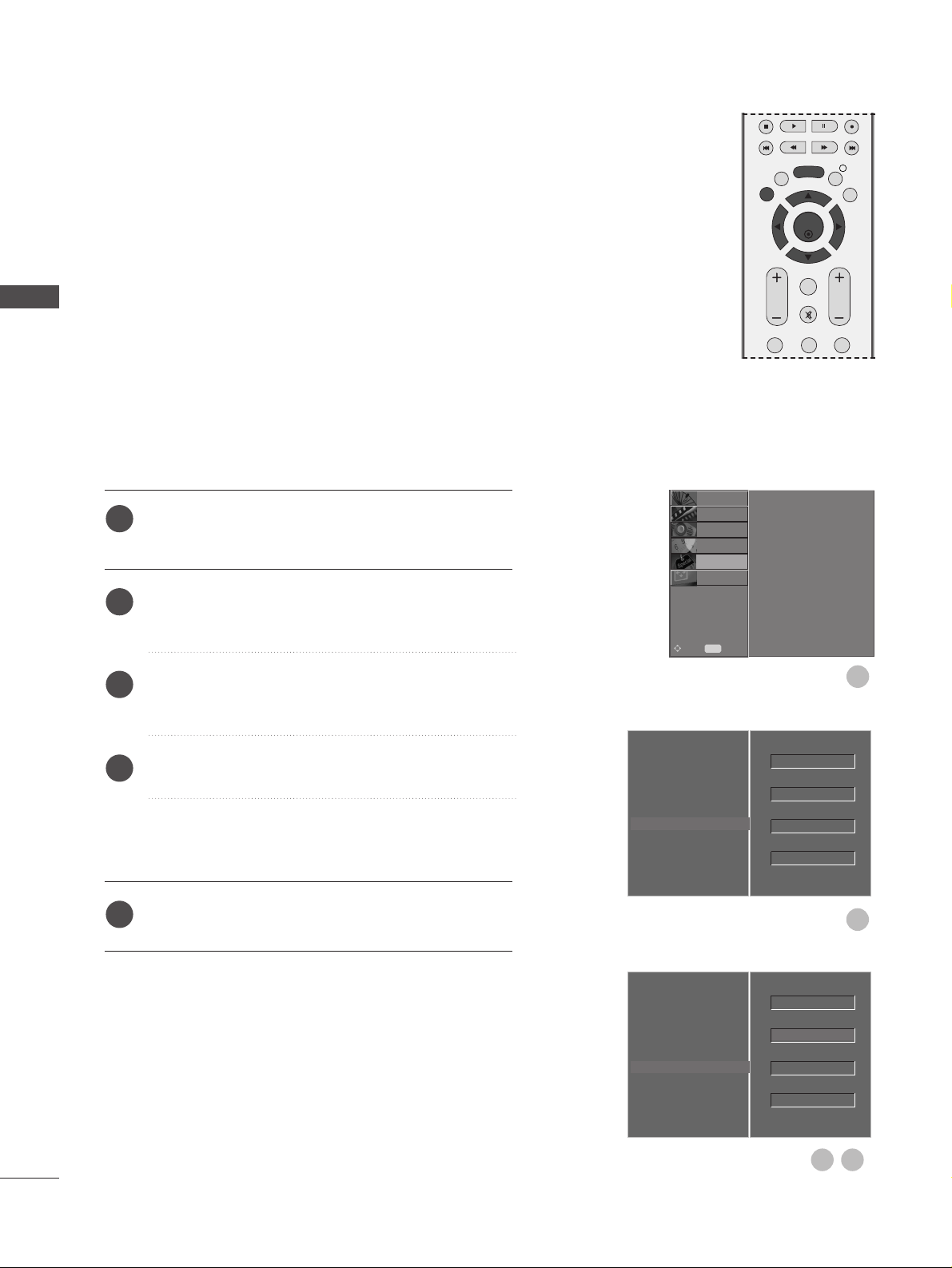
If the picture is not clear after auto adjustment and especially if
characters are still trembling, adjust the picture phase manually.
To correct the screen size, adjust Clock.
This function works in the following mode : RGB[PC].
Clock This function is to minimize any vertical bars or stripes
visible on the screen background the horizontal screen
size will also change.
Phase This function allows you to remove any horizontal noise
and clear or sharpen the image of characters.
H-Position / V-Position This function is to adjust picture to
left/right and up/down as you prefer.
Press the MENU button and then
D
or
E
button to
select the SCREEN menu.
Press the
G
button and then
D
or
E
button to select
Manual Config..
Press the
G
button and then
D
or
E
button to select
Phase, Clock, H-Position or V-Position.
Press the
F
or
G
button to make appropriate
adjustments.
Press the EXIT button to return to normal TV viewing.
Adjustment for screen Phase, Clock, Position
Auto Config.
Manual Config.
G
XGA Mode
Aspect Ratio
Reset
Phase
Clock
H-Position
V-Position
0
0
0
0
1
1
2
3
4
5
Auto Config.
Manual Config.
XGA Mode
Aspect Ratio
Reset
SETUP
O
PICTURE
O
Prev.
MENU
Move
AUDIO
O
TIME
O
OPTION
O
SCREEN G
3 4
2
OK
EXIT
VOL PR
GUIDE
BACK
MENU
123
MUTE
INFO i
FAV
EXTERNAL EQUIPMENT SETUP
Page 27
25
To view a normal picture, match the resolution of RGB mode
and selection of XGA mode.
This function works in the following mode: RGB[PC] mode
Press the MENU button and then
D
or
E
button to
select the SCREEN menu.
Press the
G
button and then
D
or
E
button to select
XGA Mode.
Press the
G
button and then
D
or
E
button to select
the desired XGA resolution.
Press the EXIT button to return to normal TV viewing.
Selecting Wide XGA mode
Auto Config.
Manual Config.
XGA Mode
G
Aspect Ratio
Reset
1024 X 768
1280 X 768
1360 X 768
1
1
2
3
4
Auto Config.
Manual Config.
XGA Mode
Aspect Ratio
Reset
SETUP
O
PICTURE
O
Prev.
MENU
Move
AUDIO
O
TIME
O
OPTION
O
SCREEN G
3
2
EXTERNAL EQUIPMENT SETUP
OK
EXIT
VOL PR
GUIDE
BACK
MENU
123
MUTE
INFO i
FAV
Page 28
26
This function operates in current mode.
To initialize the adjusted value
Press the MENU button and then
D
or
E
button to
select the OPTION menu.
Press the
G
button and then
D
or
E
button to select
Factory Mode.
Press the
G
button and then
D
or
E
button to select
Factory Reset.
Press the OK button.
The message “If you enter a password, all user
setting will be reset” will appear.
Use NUMBER buttons to input a 4-digit password.
Initializing (Reset to original factory settings)
1
2
3
4
5
Language
Country
Lock System
Parental Control
Input Label
SIMPLINK
Factory Mode
G
Set ID
Factory Reset
ISM Method
Low Power
1
2
Language
Country
Lock System
Parental Control
Input Label
SIMPLINK
Factory Mode
SETUP
O
PICTURE
O
SCREEN
O
Prev.
MENU
Move
AUDIO
O
TIME
O
OPTION G
Language
Country
Lock System
Parental Control
Input Label
SIMPLINK
Factory Mode
Set ID
Factory Reset
ISM Method
Low Power
OK
4
3
OK
Normal
Off
1
Normal
Off
1
OK
EXIT
VOL PR
GUIDE
BACK
MENU
123
MUTE
INFO i
FAV
EXTERNAL EQUIPMENT SETUP
Page 29
27
WATCHING TV / PROGRAMME CONTROL
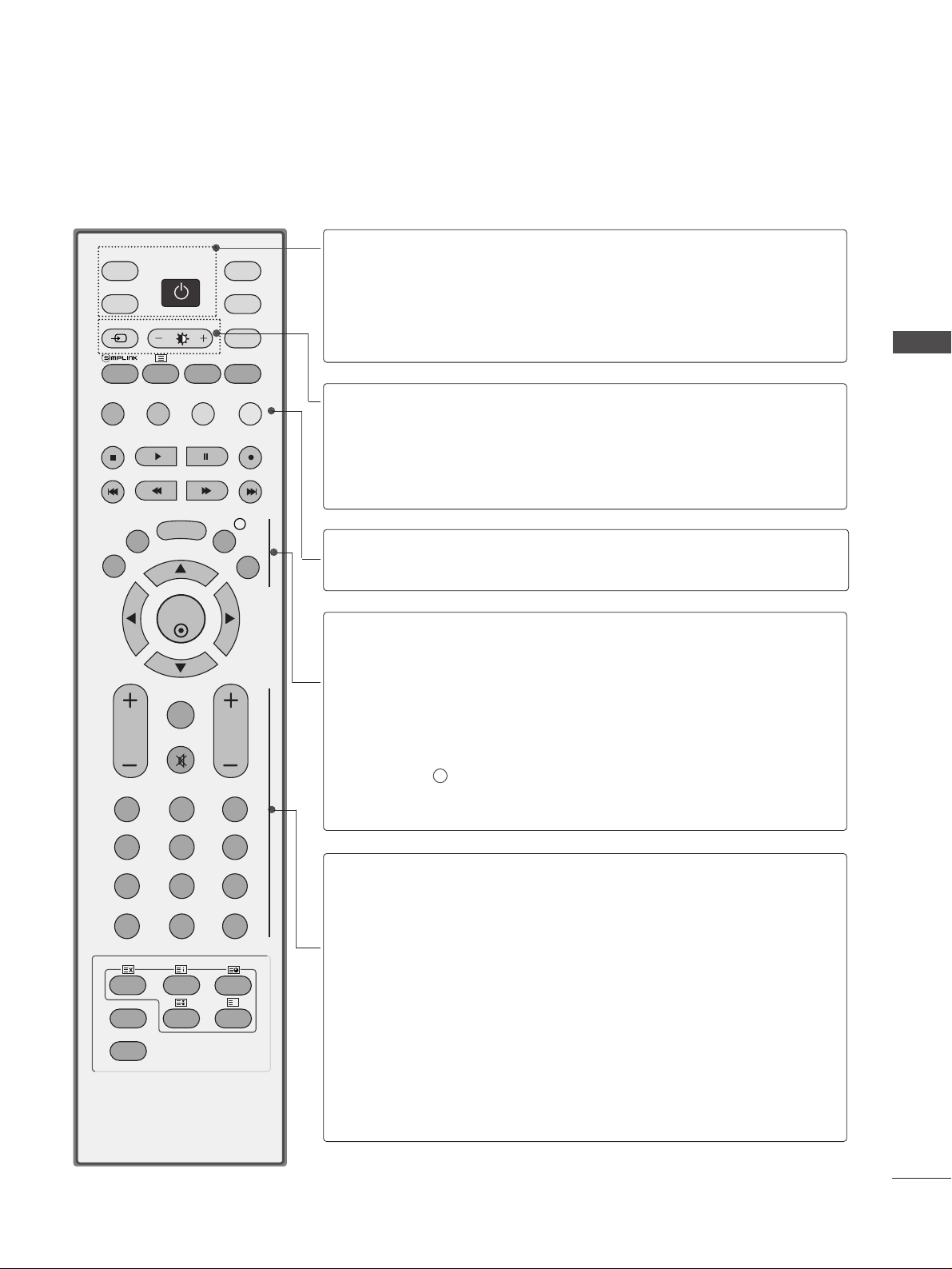
REMOTE CONTROL KEY FUNCTIONS
When using the remote control, aim it at the remote control sensor on the TV.
OK
INPUT MODE
TV
D/A
DVD
EXIT
VOL PR
GUIDE
BACK
MENU
RATIO
I/II
VCR
POWER
123
456
789
0
Q.VIEW
LIST
INDEX
SLEEP
HOLD
REVEAL
?
SUBTITLE
TEXT
INPUT
BRIGHT
MUTE
TV/RADIO
UPDATE
SIMPLINK
INFO i
FAV
TIME
POWER
D/A INPUT
TV/RADIO
Switches the TV on from standby or off to standby.
Selects digital or analogue mode.
Switches the TV on from standby.
Selects Radio or TV channel in digital mode.
INPUT
Brightness
adjustment
External input mode rotate in regular sequence.
Switches the TV on from standby.
Adjusts screen brightness.
This returns to the default settings brightness by
changing mode source.
Coloured
buttons
These buttons are used for teletext (on TELETEXT
models only) or
PPrrooggrraa mm mm ee eeddiitt
.
EXIT
BACK
MENU
INFO i
GUIDE
Clears all on-screen displays and returns to TV viewing
from any menu.
Allows the user to move back one step in an interactive
application, EPG or other user interaction function.
Selects a menu.
Shows the present screen information.
Shows programme schedule.
VOLUME UP
/DOWN
FAV
MUTE
Programme
UP/DOWN
0~9 number
button
LIST
Q.VIEW
Adjusts the volume.
Displays the selected favourite programme.
Switches the sound on or off.
Selects a programme.
Selects a programme.
Selects numbered items in a menu.
Displays the programme table.
Returns to the previously viewed programme.
WATCHING TV / PROGRAMME CONTROL
Page 30
28
WATCHING TV / PROGRAMME CONTROL
WATCHING TV / PROGRAMME CONTROL
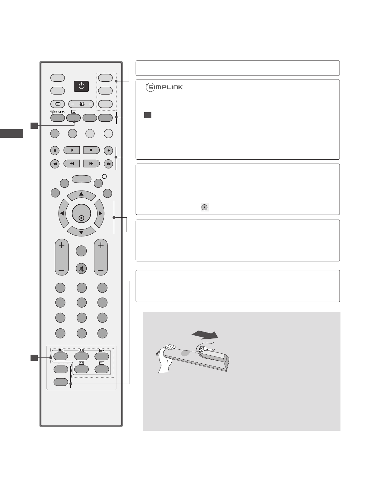
Installing Batteries
■
Open the battery compartment cover on the back and install the
batteries matching correct polarity (+with +,-with -).
■
Install two 1.5V AA batteries. Do not mix old or used batteries
with new ones.
■
Close cover.
OK
INPUT MODE
TV
D/A
DVD
EXIT
VOL PR
GUIDE
BACK
MENU
RATIO
I/II
VCR
POWER
123
456
789
0
Q.VIEW
LIST
INDEX
SLEEP
HOLD
REVEAL
?
SUBTITLE
TEXT
INPUT
BRIGHT
MUTE
TV/RADIO
UPDATE
SIMPLINK
INFO i
FAV
TIME
1
1
MODE
Selects the remote operating modes.
TELETEXT
BUTTONS
RATIO
I/II
See a list of AV devices connected to TV.
When you toggle this button, the Simplink menu appears
at the screen. (
G p.47)
These buttons are used for teletext.
For further details, see the ‘Teletext’ section.
Selects your desired picture format.
Selects the sound output.
THUMBSTICK
(Up/Down/Left
Right)
OK
Allows you to navigate the on-screen menus and adjust
the system settings to your preference.
Accepts your selection or displays the current mode.
SLEEP
SUBTITLE
Sets the sleep timer.
Recalls your preferred subtitle in digital mode.
VCR/DVD
control buttons
Controls some video cassette recorders or DVD players
when you have already selected DVD or VCR mode button.
Control connected AV devices by pressing the
DD
or EEor
FF
or GG, OK buttons and buttons for play, stop, pause,
fast reverse, fast forward, chapter skip.
(The button does not provide such functions.)
1
Page 31

29
Firstly, connect the power cord correctly.
At this stage, the TV switches to standby mode.
In standby mode to turn TV on, press the
rr
/ I, INPUT or
PR
D
or Ebutton on the TV or press the POWER,
INPUT, D/A, PR + or - or NUMBER button on the remote
control and the TV will switch on.
2
1
TURNING ON THE TV
- When your TV is turned on, you will be able to use its features.
OK
INPUT MODE
TV
D/A
DVD
EXIT
VOL PR
GUIDE
BACK
MENU
RATIO
I/II
VCR
POWER
123
456
789
0
LIST
TEXT
INPUT
BRIGHT
MUTE
TV/RADIO
SIMPLINK
INFO i
FAV
Q.VIEW
INDEX
SLEEP
HOLD
REVEAL
?
SUBTITLE
UPDATE
TIME
WATCHING TV / PROGRAMME CONTROL
Initializing setup
Note:
■
It will automatically disappear after approx. 30 seconds
unless a button is pressed.
■
Press the BACK button to change the current OSD to
the previous OSD.
■
"Home” mode is the optimal setting for home environments, and is the TV's default mode.
■
"In Store" mode is the optimal setting for store environments.“ If a user modifies image quality data, “In Store”
mode initializes the product to the image quality set by
us after a certain period of time.
■
The mode (Home, In Store) can be changed by executing Factory Reset in the OPTION menu.
If the OSD (On Screen Display) is displayed on the screen
after turning on the TV, you can adjust Auto programme
tuning.
Page 32

30
WATCHING TV / PROGRAMME CONTROL
PROGRAMME SELECTION
Press the
PPRR ++ or--
or NUMBER buttons to select a
programme number.
1
VOLUME ADJUSTMENT
Press the VOL
++ or--
button to adjust the volume.
If you wish to switch the sound off, press the MUTE
button.
You can cancel this function by pressing the MUTE,
VOL
++ or--
, or I/II button.
1
OK
INPUT MODE
TV
D/A
DVD
EXIT
VOL PR
GUIDE
BACK
MENU
RATIO
I/II
VCR
POWER
123
456
789
0
LIST
TEXT
INPUT
BRIGHT
MUTE
TV/RADIO
SIMPLINK
INFO i
FAV
Q.VIEW
INDEX
SLEEP
HOLD
REVEAL
?
SUBTITLE
UPDATE
TIME
WATCHING TV / PROGRAMME CONTROL
Page 33

31
ON-SCREEN MENUS SELECTION AND ADJUSTMENT
Press the
MMEENN UU
button and thenDDor EEbutton to display each menu.
Press the
GG
button and thenDDor EEbutton to select a menu item.
Change the setting of an item in the sub or pull-down menu with
F or G button.
You can move to a higher level menu by pressing the OK or MENU button.
Your TV's OSD (On Screen Display) may differ slightly from that shown in this manual.
2
3
1
Auto Tuning
Manual Tuning
Programme Edit
5V Antenna Power
Booster
Software Update
Diagnostics
PICTURE
O
AUDIO
O
TIME
O
OPTION
O
SCREEN
O
Prev.
MENU
Move
Picture Mode
Colour Temperature
Advanced
Picture Reset
Demo
SETUP
O
AUDIO
O
TIME
O
OPTION
O
SCREEN
O
Prev.
MENU
Move
Sound Mode
Auto Volume
Balance 0
TV Speaker
Digital Audio
SETUP
O
PICTURE
O
TIME
O
OPTION
O
SCREEN
O
Prev.
MENU
Move
SETUP G
PICTURE G
AUDIO G
Clock
Off Time
On Time
Auto Sleep
Time Zone
SETUP
O
PICTURE
O
OPTION
O
SCREEN
O
Prev.
MENU
Move
AUDIO
O
TIME G
Auto Config.
Manual Config.
XGA Mode
Aspect Ratio
Reset
SETUP
O
PICTURE
O
Prev.
MENU
Move
AUDIO
O
TIME
O
OPTION
O
SCREEN G
Language
Country
Lock System
Parental Control
Input Label
SIMPLINK
Factory Mode
SETUP
O
PICTURE
O
SCREEN
O
Prev.
MENU
Move
AUDIO
O
TIME
O
OPTION G
WATCHING TV / PROGRAMME CONTROL
Digital mode only
Setup MENU Picture MENU
Audio MENU
Time MENUOption MENU
Screen MENU
Page 34

32
WATCHING TV / PROGRAMME CONTROL
Use this to automatically find and store all available programmes.
When you start auto programming in digital mode, all previously
stored service information will be deleted.
AUTO PROGRAMME TUNING (IN DIGITAL MODE)
1
Auto Tuning G
Manual Tuning
Programme Edit
5V Antenna Power
Booster
Software Update
Diagnostics
Start
2
3
Press the MENU button and then
D
or
E
button to
select the SETUP menu.
Press the
G
button and then
D
or
E
button to select
Auto Tuning.
Press the
G
button to begin auto tuning.
Use NUMBER buttons to input a 4-digit password in
Lock System ‘On’.
The message “All service-information will be
updated. Continue?” will appear.
If you want to keep on auto tuning select YES using
the
F
or
G
button. Then, press the OK button.
Otherwise select NO.
To stop auto tuning, press the MENU button.
Press the EXIT button to return to normal TV viewing.
2
3
4
1
Auto Tuning
Manual Tuning
Programme Edit
5V Antenna Power
Booster
Software Update
Diagnostics
PICTURE
O
AUDIO
O
TIME
O
OPTION
O
SCREEN
O
Prev.
MENU
Move
SETUP G
Auto Tuning
MENU
Stop
24 %
UHF CH.
14
0 Programme(s)
0 Programme(s)
OK
EXIT
VOL PR
GUIDE
BACK
MENU
123
MUTE
INFO i
FAV
WATCHING TV / PROGRAMME CONTROL
Page 35

33
Auto Tuning
Manual Tuning
G
Programme Edit
5V Antenna Power
Booster
Software Update
Diagnostics
Your receiver will
add this channel to
your channel list.
UHF CH.
35
Manual Tuning lets you manually add a programme to your
programme list.
MANUAL PROGRAMME TUNING (IN DIGITAL MODE)
1
2
Auto Tuning
Manual Tuning
Programme Edit
5V Antenna Power
Booster
Software Update
Diagnostics
Your receiver will
add this channel to
your channel list.
UHF CH
35
43
Press the MENU button and then
D
or
E
button to
select the SETUP menu.
Press the
G
button and then
D
or
E
button to select
Manual Tuning.
Press the
G
button and then
D
or
E
button or NUMBER buttons to select the desired channel number.
Use NUMBER buttons to input a 4-digit password in
Lock System ‘On’.
Press the OK button to save.
When the channel number you want to add is already
in the programme list, the message “Setup
information for the channel will be
updated. Continue?” will appear.
If you wish to continue manual tuning, select YES
using the
F
or
G
button.
Then, press OK. Otherwise select NO.
Press the EXIT button to return to normal TV viewing.
2
3
4
5
1
D
E
Auto Tuning
Manual Tuning
Programme Edit
5V Antenna Power
Booster
Software Update
Diagnostics
PICTURE
O
AUDIO
O
TIME
O
OPTION
O
SCREEN
O
Prev.
MENU
Move
SETUP G
Search
OK
EXIT
VOL PR
GUIDE
BACK
MENU
123
MUTE
INFO i
FAV
WATCHING TV / PROGRAMME CONTROL
Page 36

34
WATCHING TV / PROGRAMME CONTROL
Auto Tuning
Manual Tuning
Programme Edit
G
5V Antenna Power
Booster
Software Update
Diagnostics
To Set
When a programme number is skipped, it means that you will be
unable to select it using PR + or - button during TV viewing.
If you wish to select the skipped programme, directly enter the
programme number with the NUMBER buttons or select it in the
Programme edit menu
This function enables you to skip the stored programmes.
PROGRAMME EDIT (IN DIGITAL MODE)
1
32
Press the MENU button and then
D
or
E
button to
select the SETUP menu.
Press the
G
button and then
D
or
E
button to select
Programme Edit menu.
Press the
G
button to enter the Programme Edit
menu.
Use NUMBER buttons to input a 4-digit password in
Lock System ‘On’.
Select a programme to be stored or skipped with the
D
or
E
or
F
or
G
button.
Press the BLUE button repeatedly to have the pro-
gramme skipped or stored.
When programmes are to be skipped, skipped
programme shows in blue and these programmes will
not be selected by the PR + or - buttons during TV
viewing.
Press the EXIT button to return to normal TV viewing.
2
3
4
5
6
1
Auto Tuning
Manual Tuning
Programme Edit
5V Antenna Power
Booster
Software Update
Diagnostics
PICTURE
O
AUDIO
O
TIME
O
OPTION
O
SCREEN
O
Prev.
MENU
Move
SETUP G
WATCHING TV / PROGRAMME CONTROL
BACK
EXIT
VOL PR
123
456
789
LIST
MENU
OK
FAV
MUTE
0
INFO i
GUIDE
Q.VIEW
Page 37

35
A Skipping a programme number
Select a programme number to be skipped with the
D
or
E
or
F
or
G
button.
Press the BLUE button. The skipped programme number turns to blue.
Press the BLUE button again to release the skipped programme.
When a programme number is skipped it means that you will be unable to select it using the PR + or button during normal TV viewing.
If you wish to select a skipped programme, directly enter the programme number with the NUMBER buttons
or select it in the programme edit or EPG.
Press the EXIT button to return to normal TV viewing.
A Locking a programme (In Lock System On mode only)
Select a programme to be locked with the
D
or
E
or
F
or
G
button.
Press the GREEN button. The lock symbol will appear in front of that programme number.
Press the GREEN button again to release this function.
Note :
G
To watch a locked programme, input a 4-digit password in Lock system. Be sure to remember this number!
G
If you forget your password, press ‘7’, ‘7’, ‘7’, ‘7’ on the remote control handset.
G
If you select another programme after releasing a locked programme and then return to the locked programme
within 1 minute, there is no need to input a password to select the locked programme.
A Selecting favourite programme
Select your favourite programme number by pressing
D
or
E
or
F
or
G
button and then press the FAV
button on your remote control handset.
This will automatically include the selected programme into your favourite programme list.
Displayed when a DTV Programme.
Displayed when a Locked Programme.
Displayed when a Radio Programme.
Mini Glossary
1
2
3
4
1
2
3
1
WATCHING TV / PROGRAMME CONTROL
Page 38

36
WATCHING TV / PROGRAMME CONTROL
Even if there isn’t a special 5V adapter power in the external
antenna, this function can output 5V in the set.
Press the MENU button and then
D
or
E
button to
select the SETUP menu.
Press the
G
button and then use
D
or
E
button to
select
5V Antenna Power
.
Press the
G
button and then use
D
or
E
button to
select
On
or
Off
.
In
5V Antenna Power On
, if the set is short-cir-
cuit, it will automatically return to
Off
.
The message “Antenna feed overloaded.
Automatically switched off.” will appear.
Press the EXIT button to return to normal TV viewing.
5V ANTENNA POWER (IN DIGITAL MODE ONLY)
1
2
3
4
Auto Tuning
Manual Tuning
Programme Edit
5V Antenna Power
G
Booster
Software Update
Diagnostics
1
32
Auto Tuning
Manual Tuning
Programme Edit
5V Antenna Power
Booster
Software Update
Diagnostics
PICTURE
O
AUDIO
O
TIME
O
OPTION
O
SCREEN
O
Prev.
MENU
Move
SETUP G
Off
On
WATCHING TV / PROGRAMME CONTROL
OK
EXIT
VOL PR
GUIDE
BACK
MENU
123
MUTE
INFO i
FAV
Page 39

37
When the interference between programmes appear, select
Booster
to
Off
.
Press the MENU button and then
D
or
E
button to
select the SETUP menu.
Press the
G
button and then
D
or
E
button to select
Booster
.
Press the
G
button and then
D
or
E
button to select
On
or
Off
.
Press the EXIT button to return to normal TV viewing.
BOOSTER (IN DIGITAL MODE ONLY)
Auto Tuning
Manual Tuning
Programme Edit
5V Antenna Power
Booster
G
Software Update
Diagnostics
Off
On
1
32
1
2
3
4
Auto Tuning
Manual Tuning
Programme Edit
5V Antenna Power
Booster
Software Update
Diagnostics
PICTURE
O
AUDIO
O
TIME
O
OPTION
O
SCREEN
O
Prev.
MENU
Move
SETUP G
WATCHING TV / PROGRAMME CONTROL
BACK
MENU
EXIT
VOL PR
123
INFO i
GUIDE
OK
FAV
MUTE
Page 40

38
WATCHING TV / PROGRAMME CONTROL
Auto Tuning
Manual Tuning
Programme Edit
5V Antenna Power
Booster
Software Update
G
Diagnostics
Off
On
1
32
65
Auto Tuning
Manual Tuning
Programme Edit
5V Antenna Power
Booster
Software Update
Diagnostics
PICTURE
O
AUDIO
O
TIME
O
OPTION
O
SCREEN
O
Prev.
MENU
Move
SETUP G
Software Update means software can be downloaded through
the digital terrestrial broadcasting system.
SOFTWARE UPDATE (IN DIGITAL MODE ONLY)
Press the MENU button and then
D
or
E
button to
select the SETUP menu.
Press the
G
button and then
D
or
E
button to select
Software update.
Press the
G
button and then
D
or
E
button to select
On or Off.
• If you select On, a user confirm message box will
be displayed to notify that new software is found.
Press the EXIT button to return to normal TV viewing.
* When setting “Software Update”
Occasionally, a transmission of updated digital
software information will result in the OSD (On
Screen Display) on the TV screen.
Select YES using the
F
or
G
button.
The OSD will be disappeared on the TV screen, and
you can watch the current TV viewing.
G When you change the TV to standby mode using the
POWER button while watching the TV, it will be started
Software update.
G Turn on the TV in standby mode. The OSD is displayed
on the screen based on Software update
circumstances.
G After the Software update is complete, the System
takes about one minute to restart.
• Power to the TV must not be interrupted.
• The TV must not be switched off.
• The antenna must not be disconnected.
• After Software Update, you can confirm the updated
software version in Diagnostics menu.
- During Progress of a Software Update, please note the following:
1
2
3
4
OK
EXIT
VOL PR
GUIDE
BACK
MENU
123
MUTE
INFO i
FAV
New software(ver. x.xx.x) is available.
Do you want to download?
?
Yes No
5
6
WATCHING TV / PROGRAMME CONTROL
Page 41

39
This function enables you to view information on the
Manufacturer, Model/Type, Serial Number and Software
Version.
This displays the information and signal strength of the
tuned MUX.
This displays the signal information and service name of the
selected MUX.
Press the MENU button and then
D or E
button to
select the SETUP menu.
Press the Gbutton and then
D or E
button to
select Diagnostics.
Press the Gbutton to display Manufacturer,
Model/Type, Serial Number and Software Version.
Press the EXIT button to return to normal TV viewing.
DIAGNOSTICS (IN DIGITAL MODE ONLY)
Auto Tuning
Manual Tuning
Programme Edit
5V Antenna Power
Booster
Software Update
Diagnostics
G
To Set
1
2
3
1
2
3
4
Auto Tuning
Manual Tuning
Programme Edit
5V Antenna Power
Booster
Software Update
Diagnostics
PICTURE
O
AUDIO
O
TIME
O
OPTION
O
SCREEN
O
Prev.
MENU
Move
SETUP G
Engineering Diagnostics
Menu
Prev.
Manufacturer : LG Electronics Inc.
Model / Type : 37LC2D-EC
Serial No. : 604KG0000006
Software Version : 1.1.0
CH 30
CH 34
Select
Transmitter : Digital Finland
Signal Strength
53%
Signal Quality
100%
1 YLE TV1 2 YLE TV2
3 YLE KLASS 4 YLE FSR+
5 YLE FST
8 YLE24
9 YLE Teema 1 YLE PEILE
Back
i Channel 30
OK
EXIT
VOL PR
GUIDE
BACK
MENU
123
MUTE
INFO i
FAV
WATCHING TV / PROGRAMME CONTROL
Page 42

40
WATCHING TV / PROGRAMME CONTROL
1
5432
All stations which can be received are stored by this
method. It is recommended that you use Auto tuning during
installation of this TV.
AUTO PROGRAMME TUNING (IN ANALOGUE MODE)
Press the MENU button and then
D
or
E
button to
select the SETUP menu.
Press the
G
button and then
D
or
E
button to select
Auto Tuning.
Press the
G
button to select System. Select a TV
system with the
F
or
G
button;
BG : PAL B/G, SECAM B/G (Europe / East Europe /
Asia / New Zealand / M.East / Africa / Australia)
I : PAL I/II (U.K. / Ireland / Hong Kong / South
Africa)
DK : PAL D/K, SECAM D/K (East Europe / China /
Africa / CIS)
Press the
E
button to select Storage From.
Select the initial programme number with the
F
or
G
button or NUMBER buttons on the Storage From
menu.
Press the
E
button to select Start.
The station name is stored for stations which
broadcast VPS (Video Programme Service), PDC
(Programme Delivery Control) or TELETEXT data.
If no station name can be assigned to a station, the
channel number is assigned and stored as C (V/UHF
01-69) or S (Cable 01-47), followed by a number.
To stop auto tuning, press the MENU button.
When auto tuning is complete, the Programme
Edit menu appears on the screen.
See the ‘Programme Edit’ section to edit the
stored programme.
Auto Tuning G
Manual Tuning
Programme Edit
System
Storage From
Start
BG
2
1
2
3
4
5
Auto Tuning
Manual Tuning
Programme Edit
PICTURE
O
AUDIO
O
TIME
O
OPTION
O
SCREEN
O
Prev.
MENU
Move
SETUP G
WATCHING TV / PROGRAMME CONTROL
BACK
EXIT
VOL PR
123
456
789
LIST
MENU
OK
FAV
MUTE
0
INFO i
GUIDE
Q.VIEW
Page 43

41
Manual Tuning lets you manually tune and arrange the
stations in whatever order you desire.
MANUAL PROGRAMME TUNING (IN ANALOGUE MODE)
Press the MENU button and then
D
or
E
button to
select the SETUP menu.
Press the
G
button and then
D
or
E
button to select
Manual Tuning.
Press the
G
button to select Storage.
Select the desired programme number with the
F
or
G
button or NUMBER buttons on the Storage menu.
Press the
E
button to select System. Select a TV
system with the
F
or
G
button;
BG : PAL B/G, SECAM B/G (Europe / East Europe /
Asia / New Zealand / M.East / Africa / Australia)
I : PAL I/II (U.K. / Ireland / Hong Kong / South
Africa)
DK : PAL D/K, SECAM D/K (East Europe / China /
Africa / CIS)
Press the
E
button to select Band. Press the
F
or
G
button to select V/UHF or Cable as required.
Press the
E
button to select Channel. You can
select the desired channel number with the
F
or
G
button or NUMBER buttons.
If possible, select the channel number directly with
the NUMBER buttons.
Press the
E
button to select Search. Press the
F
or
G
button to commence searching. If a station is
found the search will stop.
Press the OK button to store the channel.
To store another channel, repeat steps 3 to 8.
Press the EXIT button to return to normal TV viewing.
Auto Tuning
Manual Tuning
G
Programme Edit
Storage
System
Band
Channel
Fine
Search
Name
1
1
C 01
BG
V/UHF
1
5
432
9
876
1
2
3
4
5
6
7
8
9
10
Auto Tuning
Manual Tuning
Programme Edit
PICTURE
O
AUDIO
O
TIME
O
OPTION
O
SCREEN
O
Prev.
MENU
Move
SETUP G
EXIT
WATCHING TV / PROGRAMME CONTROL
BACK
MENU
INFO i
GUIDE
VOL PR
123
456
789
LIST
OK
FAV
MUTE
0
Q.VIEW
Page 44

42
WATCHING TV / PROGRAMME CONTROL
Press the MENU button and then
D
or
E
button to
select the SETUP menu.
Press the
G
button and then
D
or
E
button to select
Manual Tuning.
Press the
G
button and then
D
or
E
button to select
Name.
Press the
G
button and then
D
or
E
button. You can
use the alphabet A to Z, numbers 0 to 9, +/ -, and
blank.
Press the
F
or
G
button to select the position and
make your choice of the second character, and so on.
Press the OK button to store it.
Press the EXIT button to return to normal TV viewing.
Normally fine tuning is only necessary if reception is poor.
Press the MENU button and then
D
or
E
button to
select the SETUP menu.
Press the
G
button and then
D
or
E
button to select
Manual Tuning.
Press the
G
button and then
D
or
E
button to select
Fine.
Press the
G
button and then
F
or
G
button to fine
tune for the best picture and sound.
Press the OK button to store settings.
Press the EXIT button to return to normal TV viewing.
FINE TUNING (IN ANALOGUE MODE)
ASSIGNING A STATION NAME (IN ANALOGUE MODE)
You can assign a station name with five characters to each
programme number.
Auto Tuning
Manual Tuning
Programme Edit
1
1
2
3
4
5
6
1
2
3
4
5
6
7
Auto Tuning
Manual Tuning
Programme Edit
PICTURE
O
AUDIO
O
TIME
O
OPTION
O
SCREEN
O
Prev.
MENU
Move
SETUP G
5
432
5
432 6
OK
EXIT
VOL PR
GUIDE
BACK
MENU
INFO i
FAV
Storage
System
Band
Channel
Fine
Search
Name
C 01
F
G
D
E
Auto Tuning
Manual Tuning
Programme Edit
1
1
C 01
BG
V/UHF
Storage
System
Band
Channel
Fine
Search
Name
FG
Store
1
BG
V/UHF
1
WATCHING TV / PROGRAMME CONTROL
Page 45

43
Press the MENU button and then
D
or
E
button to
select the SETUP menu.
Press the
G
button and then
D
or
E
button to select
Programme Edit.
Press the
G
button to display the Programme Edit menu.
A Deleting a programme
Select a programme to be deleted with the
D
or
E
or
F
or
G
button.
Press the RED button twice. The selected programme
is deleted, all the following programmes are shifted
up one position.
A Copying a programme
Select a programme to be copied with the
D
or
E
or
F
or
G
button.
Press the GREEN button. All the following programmes
are shifted down one position.
This function enables you to delete or skip the stored programmes.
You can also move some channels to other programme numbers or
copy blank channel data into a selected programme number.
PROGRAMME EDIT (IN ANALOGUE MODE)
1
2
Auto Tuning
Manual Tuning
Programme Edit
G
To Set
1
2
3
a
b
a
b
Auto Tuning
Manual Tuning
Programme Edit
PICTURE
O
AUDIO
O
TIME
O
OPTION
O
SCREEN
O
Prev.
MENU
Move
SETUP G
WATCHING TV / PROGRAMME CONTROL
BACK
EXIT
MENU
OK
INFO i
GUIDE
Page 46

44
WATCHING TV / PROGRAMME CONTROL
A Moving a programme
Select a programme to be moved with
D
or
E
or
F
or
G
button.
Press the YELLOW button.
Move the programme to the desired programme number with the
D
or
E
or
F
or
G
button.
Press the YELLOW button again to release this function.
A Skipping a programme number
Select a programme number to be skipped with
D
or
E
or
F
or
G
button.
Press the BLUE button. The skipped programme number turns to blue.
Press the BLUE button to release the skipped programme.
When a programme number is skipped it means that you will be unable to select it using the PR + or button during normal TV viewing.
If you wish to select the skipped programme, directly enter the programme number with the NUMBER
buttons or select it in the programme edit or table menu.
A Selecting a Favourite Programme
Select your favourite programme number with
D
or
E
or
F
or
G
button.
Press the FAV button.
The selected programme will be added to the favourite programme list.
a
b
c
d
a
b
a
b
c
d
OK
EXIT
GUIDE
BACK
MENU
RATIO
I/II
TEXT
SIMPLINK
INFO i
VOL PR
123
456
789
0
LIST
MUTE
FAV
Q.VIEW
WATCHING TV / PROGRAMME CONTROL
Page 47

45
A Displaying programme LIST
Press the LIST button to display the PROGRAMME
LIST menu.
The programme list appears on the screen.
• You may find some blue programmes.
These have been set up to be skipped by auto
programming or in the programme edit mode.
• Some programmes with the channel number shown
in the programme LIST indicate there is no station
name assigned.
A Selecting a programme in the programme list
Select a programme with the
D
or
E
button.
Press the OK button. The TV switches to the chosen
programme number.
A Paging through a programme list (Digital Mode Only)
Press the PR + or - button repeatedly to turns the
pages.
Press the LIST button to return to normal TV viewing.
A Displaying the favourite programme table
Press the FAV button to display the Favourite
Programme table menu.
You can check which programmes are stored in the memory
by displaying the programme table.
SELECTING THE PROGRAMME TABLE
Displayed when the
Favourite Programme.
Displayed when the
Locked Programme.
Mini Glossary
1
1
2
1
2
OK
VOL PR
MUTE
FAV
789
0
LIST
Q.VIEW
< In Digital Mode >
DTV List
D
E
1 YLE TV1
2 YLE TV2
3 YLE FST
4 YLE 24
5
YLE Teema
6TV4
7 TV4 Film
8 TV4 400
9 TV4 Plus
10 CNN
< In Analogue Mode >
Programme List
0 BBC1
1C 01
2C 04
3C 43
4 C 05
5 BLN 2
6
S 04
7
S 05
8
S 07
9
S 12
WATCHING TV / PROGRAMME CONTROL
Page 48

46
WATCHING TV / PROGRAMME CONTROL
Selects a label for each input source which is not in use.
Press the MENU button and then
D
or
E
button to select
the OPTION menu.
Press the
G
button and then
D
or
E
button to select Input
Label.
Press the
G
button and then
D
or
E
button to select the
source.
Press the
F
or
G
button to select the label.
Press the EXIT button to return to normal TV viewing.
INPUT SOURCE SELECTION
Language
Country
Lock System
Parental Control
Input Label
G
SIMPLINK
Factory Mode
AV
Comp1
Comp2
RGB
HDMI1
HDMI2
HDMI3
HDMI4
1
1
2
3
4
5
Language
Country
Lock System
Parental Control
Input Label
SIMPLINK
Factory Mode
SETUP
O
PICTURE
O
SCREEN
O
Prev.
MENU
Move
AUDIO
O
TIME
O
OPTION G
3 42
OK
EXIT
VOL PR
GUIDE
BACK
MENU
123
MUTE
INFO i
FAV
WATCHING TV / PROGRAMME CONTROL
Page 49

47
Press the MENU button and then
D
or
E
button to
select the OPTION menu.
Press the
G
button and then
D
or
E
button to select
SIMPLINK.
Press the
G
button and then
D
or
E
button to select
On or Off.
Press the EXIT button to return to normal TV viewing.
Language
Country
Lock System
Parental Control
Input Label
SIMPLINK
G
Factory Mode
Off
On
1
1
2
3
4
Language
Country
Lock System
Parental Control
Input Label
SIMPLINK
Factory Mode
SETUP
O
PICTURE
O
SCREEN
O
Prev.
MENU
Move
AUDIO
O
TIME
O
OPTION G
FUNCTION
This function operates only with devices with the SIMPLINK
logo. Please check the SIMPLINK logo.
This TV might not function properly when using it with
other products with HDMI-CEC function.
This allows you to control and play other AV devices
connected to the display through HDMI cable without
additional cables and settings.
If you do not require the SIMPLINK menu, select “Off”.
SIMPLINK function is not supported by HDMI IN 3,4 input.
32
OK
EXIT
VOL PR
GUIDE
BACK
MENU
123
MUTE
INFO i
FAV
WATCHING TV / PROGRAMME CONTROL
Page 50

48
WATCHING TV / PROGRAMME CONTROL
NOTE
!
GG
Connect the HDMI/DVI IN or HDMI IN terminal of the TV to the rear terminal (HDMI terminal) of the
SIMPLINK device with the HDMI cable.
GG
After connecting the HDMI terminal for the home theatre with the SIMPLINK function using the above
method, connect the DIGITAL AUDIO OUT terminal on the back of the TV to the DIGITAL AUDIO IN terminal on the back of the SIMPLINK device with the OPTICAL cable.
GG
When operating an external device with SIMPLINK, press the TV button from the MODE buttons on the
remote control.
GG
When you switch the Input source using the INPUT button on the remote control, you can stop the operation of a device controlled by SIMPLINK.
GG
When you select or operate a media device with home theatre function, the speaker automatically switches
to home theatre speaker (HT speaker).
DDiisscc ppllaayybbaacckk
Control connected AV devices by pressing the
DD
or EEor FFor
GG
, OK, , , , , , and
buttons.
DDiirreecctt PPllaayy
After connecting AV devices to the TV, you can directly control the devices and play media without additional settings.
SSeelleecctt AAVV ddeevv iiccee
Enables you to select one of the AV devices connected to the TV and operate it.
PPoowweerr ooffff aallll ddeevviicceess
When you switch off the TV, all connected devices are turned off.
SSwwiittcchh aauuddiioo--oouutt
Offers an easy way to switch audio-out.
**
A device, which is connected to the TV through a HDMI cable but does not support SIMPLINK, does not provide this function.
SIMPLINK Functions
TTVV vviieewwii nngg ::
Switch to the previous TV programme
regardless of the current mode.
DDIISSCC pp llaayybbaacckk ::
Select and play connected discs.
When multiple discs are available, the titles of discs are
conveniently displayed at the bottom of the screen.
VVCCRR ppllaayybbaa cckk ::
control the connected VCR.
HHDD DD RReeccoorrddii nnggss pp llaayybbaacckk ::
control recordings
stored in HDD.
AAuuddiioo OOuutt ttoo HHoommee tthheeaattrree //AAuuddiioo OOuutt ttoo TTVV::
Select Home theatre or TV speaker for Audio Out.
Selected Device
When no device is connected
(displayed in gray)
When a device is connected
(displayed in bright colour)
1
2
3
4
5
1
2
3
4
5
SIMPLINK Menu
Press the
DD
or EEor FFor
GG
button and then OK button to select the desired SIMPLINK source.
WATCHING TV / PROGRAMME CONTROL
Page 51

49
EPG (ELECTRONIC PROGRAMME GUIDE) (IN DIGITAL MODE)
Press the GUIDE button to switch on EPG.
Press the GUIDE or EXIT button again to switch off EPG and return to normal TV viewing.
Press the
D
or E, F or G, PR + or - button to select
the desired programme, then the OK button, the
popup window to select the function is displayed.
This system has an Electronic Programme Guide (EPG) to help your navigation through all the
possible viewing options.
The EPG supplies information such as programme listings, start and end times for all available
services. In addition, detailed information about the programme is often available in the EPG (the
availability and amount of these programme details will vary, depending on the particular
broadcaster).
This function can be used only when the EPG information is broadcast by broadcasting companies.
The EPG displays the programme details for next 8 days.
Switch On/Off EPG
Select Programme
1
2
1
Programme Guide
D
E
6 BBC Channel 14 : 35 3 Apr
E
DTV 14:30 15:00 15:30 11 Apr
6 BBC Channel The Tre Story Of Tra Animadness...
G
1 BBC ONE Mona The va... The Wild Thor The Wild Thoo
G
2 BBC TWO Racing A BBC News Sports BBC News
G
3 BBC THREE This is BBC THREE Welcome Welcome To
G
4 BBC NEWS 24 BBC BBC NEWS BBC News
G
5 BBCi BBCi Racing News Welcome To
G
7 BBC1 London Racing BBC THREE The Wild Thorr
G
Radio
TV/RADIO
Mode
Date Manual Timer Schedule List
Favourite
FAV
Information
INFO
PR. Change
EPG (ELECTRONIC PROGRAMME GUIDE) (IN DIGITAL MODE)
Page 52

50
EPG (ELECTRONIC PROGRAMME GUIDE) (IN DIGITAL MODE)
Remote Control Buttons
Function
RED Change EPG mode
YELLOW Enter Timer Remind setting mode
BLUE Enter Timer Remind list mode
Change to the selected channel
F
or
G
Select NOW or NEXT Programme
D
or
E
Select the Broadcast Programme
PR + or - Page Up/Down
GUIDE/EXIT Switch off EPG
TV/RADIO Select TV or RADIO Programme
INFO i Detail information on or off
Remote Control Buttons
Function
RED Change EPG mode
GREEN Enter Date setting mode
YELLOW Enter Timer Remind setting mode
BLUE Enter Timer Remind list mode
Change to the selected channel
F
or
G
Select NOW or NEXT Programme
D
or
E
Select the Broadcast Programme
PR + or - Page Up/Down
GUIDE/EXIT Switch off EPG
TV/RADIO Select TV or RADIO Programme
INFO i Detail information on or off
Button Function in NOW/NEXT Guide Mode
Button Function in 8 Day Guide Mode
Button Function in Date Change Mode
Remote Control Buttons
Function
GREEN Switch off Date setting mode
Change to the selected date
F
or
G
Select a date
E
Switch off Date setting mode
GUIDE/EXIT Switch off EPG
Programme Guide
D
E
6 BBC Channel 14 : 35 3 Apr
Mode
Manual Timer Schedule List
Favourite
FAV
Information
INFO
PR. Change
DTV NOW NEXT
6 BBC Channel Mona The Vampire The Wild Thornberrys
1 BBC ONE Racing From Aintree BBC News Special
2 BBC TWO This is BBC THREE Welcome To BBC THREE
3 BBC THREE BBC News BBC News
4 BBC NEWS 24 BBCi BBCi
5 BBCi The Story Of Tracy oooo Animadness
7 BBC1 London BBC News BBC News
Programme Guide
D
E
6 BBC Channel 14 : 35 3 Apr
E
DTV 14:30 15:00 15:30 11 Apr
6 BBC Channel The Tre Story Of Tra Animadness...
G
1 BBC ONE Mona The va... The Wild Thor The Wild Thoo
G
2 BBC TWO Racing A BBC News Sports BBC News
G
3 BBC THREE This is BBC THREE Welcome Welcome To
G
4 BBC NEWS 24 BBC BBC NEWS BBC News
G
5 BBCi BBCi Racing News Welcome To
G
7 BBC1 London Racing BBC THREE The Wild Thorr
G
Radio
TV/RADIO
Mode
Date Manual Timer Schedule List
Favourite
FAV
Information
INFO
PR. Change
Programme Guide
D
E
6 BBC Channel 14 : 35 3 Apr
E
F
Today G14:30 15:00 15:30 11 Apr
6 BBC Channel The Tre Story Of Tra Animadness...
G
1 BBC ONE Mona The va... The Wild Thor The Wild Thoo
G
2 BBC TWO Racing A BBC News Sports BBC News
G
3 BBC THREE This is BBC THREE Welcome Welcome To
G
4 BBC NEWS 24 BBC BBC NEWS BBC News
G
5 BBCi BBCi Racing News Welcome To
G
7 BBC1 London Racing BBC THREE The Wild Thorr
G
Date Exit
Date Change
Radio
TV/RADIO
EPG (ELECTRONIC PROGRAMME GUIDE) (IN DIGITAL MODE)
Page 53

51
Button Function in Extended Description Box
Remote Control Buttons
Function
D
or
E
Text Up/Down
INFO i The detail information on or off
PR + or - Page Up/Down
GUIDE/EXIT Switch off EPG
Button Function in Remind Mode
Remote Control Buttons
Function
YELLOW Change to Guide mode
Save Timer Remind
F
or
G
Select Service, Date or Start time
D
or
E
Function setting
Button Function in Schedule List Mode
Remote Control Buttons
Function
YELLOW Add new Manual Timer setting mode
GREEN Enter Schedule list editing mode
RED Delete the selected item
BLUE Change to Guide mode
D
or
E
Select Schedule list
Manual Timer
D
E
CancelSave
Remind 07 BBC THREE 28 Feb 22 : 35 23 : 00
Type Programme Date Start End
14 : 35 3 Apr
Schedule List
D
E
1 BBC TWO 08:00 Fri 23 Feb Remind
14 : 35 3 Apr
Delete Edit New Guide
Title Programme Date Time
Friends 01 BBC TWO Wed 23 Feb 08:00
Newsnight review 02 BBC TWO Fri 25 Feb 23:00
Road trip 02 BBC TWO Set 26 Feb 00:35
BBC News 07 BBC THREE Fri 25 Feb 12:00
Carrott Gold 01 BBC ONE Mon 28 Feb 22:35
Information
Friends 14 : 35 3 Apr
Manual Timer
Info Exit
INFO
Mona The Vampire Record
14:00 15:20 3 Apr
Miss Gotto’s Haunted House/Cry Of the Swamp; Miss Gotto Wail Moves
into a new house, and there’s mysterious wail enanating from the local
sweep Of The Swamp; Miss Gotto Wail Moves into a new house, and there’s
a mysterious wail enanating from the local sweep Of The Swamp; Miss Gotto
Wail Moves into a new house, and there’s a mysterious wail enanating from
the local sweep Of The Swamp; Miss Gotto Wail Moves into a new house,
and there’s a mysterious wail enanating from the local sweep Of The Swamp
EPG (ELECTRONIC PROGRAMME GUIDE) (IN DIGITAL MODE)
Page 54

•
1166:: 99
The following selection will allow you to adjust
the picture horizontally, in linear proportion,
to fill the entire screen (useful for viewing 4:3
formatted DVDs).
•
OOrriiggiinnaa ll
When your TV receives a wide screen signal it
will automatically change to the picture format
broadcast.
•
44:: 33
The following selection will allow you to view
a picture with an original 4:3 aspect ration,
grey bars will appear on both the left and
right of the screen.
•
1144:: 99
You can view a picture format of 14:9 or a
general TV programme in the 14:9 mode. The
14:9 screen is viewed in the same way as in
4:3, but is magnified to the left and right.
52
PICTURE CONTROL
PICTURE CONTROL
14:9
DE
4:3
16:9
You can watch the screen in various picture formats;
1166:: 99, OOrriiggiinnaa ll
,
44:: 33, 1144:: 99
and
ZZoo oo mm 11//22
.
If a fixed image is displayed on the screen for a long time, that fixed
image may become imprinted on the screen and remain visible.
You can adjust the screen position using
D
or
E
button.
PICTURE SIZE (ASPECT RATIO) CONTROL
Press the
RRAA TTIIOO
button repeatedly to select the desired picture format.
You can also adjust Aspect Ratio in the SCREEN menu.
1
Original
OK
EXIT
GUIDE
BACK
MENU
RATIO
I/II
VCR
TEXT
SIMPLINK
INFO i
FAV
Page 55

53
•
ZZoo oo mm 11
The following selection will allow you to view
the picture without any alteration, while filling
the entire screen. However, the top and
bottom of the picture will be cropped.
•
ZZoo oo mm 22
Choose Zoom 2 when you wish the picture to
be altered, both horizontally extended and
vertically cropped. The picture adopting a
compromise between alteration and screen
coverage.
NOTE
!
G
You can only select Original, 14:9 in DTV, TV or AV mode.
G
You can not select Zoom1/2 in RGB/HDMI[PC] mode only.
Zoom1
DE
Zoom2
DE
PICTURE CONTROL
Page 56

54
PICTURE CONTROL
Press the MENU button and then
D
or
E
button to
select the PICTURE menu.
Press the
G
button and then
D
or
E
button to select
Picture Mode.
Press the
G
button and then
D
or
E
button to select
Vivid, Standard, Cinema, User 1 or User 2.
Press the EXIT button to return to normal TV viewing.
Picture Mode adjusts the TV for the best picture
appearance. Select the preset value in the Picture
Mode menu based on the programme category.
Vivid, Standard and Cinema are programmed
for optimum picture
reproduction at the factory and cannot be changed.
Vivid Select this option to display a sharp image.
Standard The most general and natural screen
display status.
Cinema Select this option to display a cinema image.
User 1/2 Select this option to use a user defined
setting.
PRESET PICTURE SETTINGS
Picture Mode-Preset
Picture Mode G
Colour Temperature
Advanced
Picture Reset
Demo
Vivid
Standard
Cinema
User 1
User 2
1
2
3
4
1
Picture Mode
Colour Temperature
Advanced
Picture Reset
Demo
SETUP
O
AUDIO
O
TIME
O
OPTION
O
SCREEN
O
Prev.
MENU
Move
PICTURE G
32
OK
EXIT
VOL PR
GUIDE
BACK
MENU
123
MUTE
INFO i
FAV
PICTURE CONTROL
Page 57

55
Press the MENU button and then
D
or
E
button to
select the PICTURE menu.
Press the
G
button and then
D
or
E
button to select
Colour Temperature.
Press the
G
button and then
D
or
E
button to select
either Cool, Medium, War m or User.
Press the EXIT button to return to normal TV viewing.
To initialize values (reset to default settings), select the Cool
option.
Choose one of three automatic colour adjustments. Set to
warm to enhance hotter colours such as red or set to cool to
see less intense colours with more blue.
It’s available to use this function in
User
mode.
Auto Colour Tone Control (Warm/Medium/Cool)
Picture Mode
Colour Temperature
G
Advanced
Picture Reset
Demo
Cool
Medium
Warm
User
1
1
2
3
4
Picture Mode
Colour Temperature
Advanced
Picture Reset
Demo
SETUP
O
AUDIO
O
TIME
O
OPTION
O
SCREEN
O
Prev.
MENU
Move
PICTURE G
32
OK
EXIT
VOL PR
GUIDE
BACK
MENU
123
MUTE
INFO i
FAV
PICTURE CONTROL
Page 58

56
PICTURE CONTROL
Contrast 50
Brightness 55
Colour 50
Sharpness 50
Tint 0
R
User 1
Picture Mode G
Colour Temperature
Advanced
Picture Reset
Demo
Vivid
Standard
Cinema
User 1
User 2
1
G
Picture Mode
Colour Temperature
Advanced
Picture Reset
Demo
SETUP
O
AUDIO
O
TIME
O
OPTION
O
SCREEN
O
Prev.
MENU
Move
PICTURE G
MANUAL PICTURE ADJUSTMENT
Press the MENU button and then
D
or
E
button to select
the PICTURE menu.
Press the
GG
button and then
DD
or
EE
button to select
Picture Mode.
Press the
G button and then
D
or
E
button to select User
1 or User 2.
Press the
GG
button and then
DD
or
EE
button to select the
desired picture option (Contrast, Brightness, Colour,
Sharpness and Tint).
Press the
GG
button and then
FF
or
GG
button to make
appropriate adjustments.
Press the EXIT button to return to normal TV viewing.
Picture Mode-User Option
NOTE
!
GG
You can not adjust colour, sharpness and tint in the
RGB/HDMI[PC] mode.
1
2
3
4
5
6
32
54
OK
EXIT
VOL PR
GUIDE
BACK
MENU
123
MUTE
INFO i
FAV
PICTURE CONTROL
Page 59

57
Picture Mode
Colour Temperature
G
Advanced
Picture Reset
Demo
Cool
Medium
Warm
User
Red 40 G
Green 0
Blue 0
User
1
Picture Mode
Colour Temperature
Advanced
Picture Reset
Demo
SETUP
O
AUDIO
O
TIME
O
OPTION
O
SCREEN
O
Prev.
MENU
Move
PICTURE G
To adjust red, green, blue to any colour temperature you prefer.
Colour Tone - User Option
Press the MENU button and then
D
or
E
button to select
the PICTURE menu.
Press the
GG
button and then
DD
or
EE
button to select
Colour Temperature.
Press the
GG
button and then
DD
or
EE
button to select User.
Press the
GG
button and then
DD
or
EE
button to select Red,
Green or Blue.
Press the
GG
button and then
FF
or
GG
button to make
appropriate adjustments.
Press the EXIT button to return to normal TV viewing.
1
2
3
4
5
6
32
54
OK
EXIT
VOL PR
GUIDE
BACK
MENU
123
MUTE
INFO i
FAV
PICTURE CONTROL
Page 60

58
PICTURE CONTROL
AA
XXDD CCoonnttrraasstt ::
Optimizes the contrast automatically
according to the brightness of the reflection.
AA
XXDD CCoolloouurr ::
Adjusts the colour of the reflection
automatically to reproduce as close as possible natural
colours.
AA
XXDD NNRR
: Removes interference up to the point where it
does not damage the original picture.
AA
MMPPEEGG NNRR
: Reduces interference which may appear on
the screen while watching the TV.
Picture Mode
Colour Temperature
G
Advanced
Picture Reset
Demo
Auto
Manual
XD Contrast
XD Colour
XD NR
MPEG NR
0
On
On
Low
Picture Mode
Colour Temperature
Advanced
Picture Reset
Demo
1
2
Picture Mode
Colour Temperature
Advanced
Picture Reset
Demo
SETUP
O
AUDIO
O
TIME
O
OPTION
O
SCREEN
O
Prev.
MENU
Move
PICTURE G
XD - PICTURE IMPROVEMENT TECHNOLOGY
3
Press the MENU button and then
D
or
E
button to select
the PICTURE menu.
Press the
GG
button and then
DD
or
EE
button to select XD.
Press the
GG
button and then
DD
or
EE
button to select
Auto or Manual.
Press the EXIT button to return to normal TV viewing.
* Manual Selection
This menu is activated after selecting User1 or User2 in the Picture
Mode.
Press theGGbutton and then DDorEEbutton to select XD
Contrast
, XD Colour, XD NR or MPEG NR.
Press the
FForGG
button to select On or Off.
Press the EXIT button to return to normal TV viewing.
XD is LG electronics unique picture improving technology to
display a real HD source through an advanced digital signal
processing algorithm.
It is not possible to use this function in RGB[PC], HDMI[PC] mode.
1
2
3
4
1
2
3
Auto
Manual
G
XD Contrast
XD Colour
XD NR
MPEG NR
0
On
On
Low
OK
EXIT
VOL PR
GUIDE
BACK
MENU
123
MUTE
INFO i
FAV
PICTURE CONTROL
Page 61

59
DEMO
Use it to see the difference between XD Demo on and XD Demo
off.
It is not possible to use this function in RGB[PC], HDMI[PC]
mode.
Press the MENU button and then
D
or
E
button to select
the PICTURE menu.
Press the
GG
button and then
DD
or
EE
button to select XD
Demo.
Press the
GG
button to begin XD Demo.
To s t o p XD Demo, press the
MMEENN UU
or
EEXXII TT
button.
1
2
3
4
Picture Mode
Colour Temperature
Advanced
Picture Reset
Demo
G
To Start
1
Picture Mode
Colour Temperature
Advanced
Picture Reset
Demo
SETUP
O
AUDIO
O
TIME
O
OPTION
O
SCREEN
O
Prev.
MENU
Move
PICTURE G
• XD Demo
XD™Off XD™ On
Exit
Menu
32
OK
EXIT
VOL PR
GUIDE
BACK
MENU
123
MUTE
INFO i
FAV
PICTURE CONTROL
Page 62

60
PICTURE CONTROL
Picture Mode
Colour Temperature
Advanced
G
Picture Reset
Demo
Cinema
Black Level
Off
Low
Picture Mode
Colour Temperature
Advanced
Picture Reset
Demo
Cinema
Black Level
Low
1
Picture Mode
Colour Temperature
Advanced
Picture Reset
Demo
SETUP
O
AUDIO
O
TIME
O
OPTION
O
SCREEN
O
Prev.
MENU
Move
PICTURE G
2
3
ADVANCED - CINEMA
To set the TV up for the best picture quality for viewing films.
This feature operates only in DTV, TV, AV, S-Video and Component
480i/576i mode.
Press the MENU button and then
D
or
E
button to select
the PICTURE menu.
Press the
GG
button and then
DD
or
EE
button to select Advanced.
Press the
GG
button and then
DD
or
EE
button to select Cinema.
Press the
FF
or
GG
button to select On or Off.
Press the EXIT button to return to normal TV viewing.
1
2
3
4
5
On
GF
OK
EXIT
VOL PR
GUIDE
BACK
MENU
123
MUTE
INFO i
FAV
PICTURE CONTROL
Page 63

61
ADVANCED - BLACK(DARKNESS) LEVEL
When you view a film this function adjusts the TV to best picture
quality.
This function works in the following mode: AV (NTSC-M), S-Video
(NTSC-M) or HDMI.
Press the MENU button and then
D
or
E
button to select
the PICTURE menu.
Press the
GG
button and then
DD
or
EE
button to select
Advanced.
Press the
GG
button and then
DD
or
EE
button to select
Black Level.
Press the
FF
or
GG
button to select Auto, Low or High.
AA
LL oo ww
::
The reflection of the screen gets darker.
AA
HHiigghh
::
The reflection of the screen gets brighter.
Press the EXIT button to return to normal TV viewing.
1
2
3
4
5
Picture Mode
Colour Temperature
Advanced
G
Picture Reset
Demo
Cinema
Black Level
Off
Low
Picture Mode
Colour Temperature
Advanced
Picture Reset
Demo
Cinema
Black Level
1
Picture Mode
Colour Temperature
Advanced
Picture Reset
Demo
SETUP
O
AUDIO
O
TIME
O
OPTION
O
SCREEN
O
Prev.
MENU
Move
PICTURE G
2
43
Off
Low
GF
OK
EXIT
VOL PR
GUIDE
BACK
MENU
123
MUTE
INFO i
FAV
NOTE
!
AA
Auto
Realizing the Black Level of the screen and set it to High
or Low automatically.
PICTURE CONTROL
Page 64

62
PICTURE CONTROL
PICTURE RESET
Press the MENU button and then
D
or
E
button to select
the PICTURE menu.
Press the
GG
button and then
DD
or
EE
button to select
Picture Reset.
Press the
GG
button to initialize the adjusted value.
Returns to the default factory setting for Picture Mode, Colour,
Temperature, XD and Advanced.
1
2
3
Picture Mode
Colour Temperature
Advanced
Picture Reset
G
Demo
To Set
1
Picture Mode
Colour Temperature
Advanced
Picture Reset
Demo
SETUP
O
AUDIO
O
TIME
O
OPTION
O
SCREEN
O
Prev.
MENU
Move
PICTURE G
32
OK
EXIT
VOL PR
GUIDE
BACK
MENU
123
MUTE
INFO i
FAV
PICTURE CONTROL
Page 65

63
A frozen or still picture from a PC/Video game displayed on the
screen for prolonged periods will result in a ghost image
remaining even when you change the image. Avoid allowing a
fixed image to remain on the screen for prolonged periods.
White Wash
White wash removes permanent images from the screen.
Note: An excessive permanent image may be impossible to clear
entirely with White Wash.
Orbiter
Orbiter may help prevent ghost images. However, it is best not
to allow any fixed image to remain on the screen. To avoid a
permanent image on the screen, the screen will move every 2
minutes.
Inversion
This function inverts the panel colour of the screen. The panel
colour is automatically inverted every 30 minutes.
Press the MENU button and then
D
or
E
button to
select the OPTION menu.
Press the
G
button and then
D
or
E
button to select
Factory Mode.
Press the
G
button and then
D
or
E
button to select
ISM Method.
Press the
FF
or
GG
button to select either Normal,
Orbiter, White Wash or Inversion.
If you do not need this function, set Normal.
Press the EXIT button to return to normal TV viewing.
IMAGE STICKING MINIMIZATION (ISM) METHOD
Language
Country
Lock System
Parental Control
Input Label
SIMPLINK
Factory Mode
G
Set ID
Factory Reset
ISM Method
Low Power
1
2
1
2
3
4
5
Language
Country
Lock System
Parental Control
Input Label
SIMPLINK
Factory Mode
SETUP
O
PICTURE
O
SCREEN
O
Prev.
MENU
Move
AUDIO
O
TIME
O
OPTION G
Language
Country
Lock System
Parental Control
Input Label
SIMPLINK
Factory Mode
Set ID
Factory Reset
ISM Method
Low Power
Normal
GF
43
OK
Normal
Off
1
OK
Off
1
OK
EXIT
VOL PR
GUIDE
BACK
MENU
123
MUTE
INFO i
FAV
PICTURE CONTROL
Page 66

64
PICTURE CONTROL
This function allows you to reduce the power consumption of
the TV.
Press the MENU button and then
D
or
E
button to
select the OPTION menu.
Press the
G
button and then
D
or
E
button to select
Factory Mode.
Press the
G
button and then
D
or
E
button to select
Low power.
Press the
FF
or
GG
button to select On or Off.
Press the EXIT button to return to normal TV viewing.
LOW-POWER PICTURE MODE
1
2
3
4
5
Language
Country
Lock System
Parental Control
Input Label
SIMPLINK
Factory Mode
G
Set ID
Factory Reset
ISM Method
Low Power
1
2
Language
Country
Lock System
Parental Control
Input Label
SIMPLINK
Factory Mode
SETUP
O
PICTURE
O
SCREEN
O
Prev.
MENU
Move
AUDIO
O
TIME
O
OPTION G
Language
Country
Lock System
Parental Control
Input Label
SIMPLINK
Factory Mode
Set ID
Factory Reset
ISM Method
Low Power
On
GF
43
OK
Normal
Off
1
OK
Normal
1
OK
EXIT
VOL PR
GUIDE
BACK
MENU
123
MUTE
INFO i
FAV
PICTURE CONTROL
Page 67

65
SOUND & LANGUAGE CONTROL
1
AVL automatically remains on the same level of volume if
you change programmes.
Press the MENU button and then
D
or
E
button to
select the AUDIO menu.
Press the
G
button and then
D
or
E
button to select
Auto Volume.
Press the
G
button and then
D
or
E
button to select
On or Off.
Press the EXIT button to return to normal TV viewing.
AUTO VOLUME LEVELER
Sound Mode
Auto Volume
G
Balance 0
TV Speaker
Digital Audio
Off
On
1
2
3
4
Sound Mode
Auto Volume
Balance 0
TV Speaker
Digital Audio
SETUP
O
PICTURE
O
TIME
O
OPTION
O
SCREEN
O
Prev.
MENU
Move
AUDIO G
32
OK
EXIT
VOL PR
GUIDE
BACK
MENU
123
MUTE
INFO i
FAV
SOUND & LANGUAGE CONTROL
Page 68

66
SOUND & LANGUAGE CONTROL
SOUND & LANGUAGE CONTROL
Sound Mode G
Auto Volume
Balance 0
TV Speaker
Digital Audio
Surround MAX
Standard
Music
Cinema
Sport
User
1
Sound Mode
Auto Volume
Balance 0
TV Speaker
Digital Audio
SETUP
O
PICTURE
O
TIME
O
OPTION
O
SCREEN
O
Prev.
MENU
Move
AUDIO G
PRESET SOUND SETTINGSSOUND MODE
You can select your preferred sound setting; Surround MAX,
Standard, Music, Cinema or Sport and you can also adjust
the frequency of the equalizer.
Sound Mode lets you enjoy the best sound without any Special
adjustment as the TV sets the appropriate sound options based
on the programme content.
Surround MAX, Standard, Music, Cinema san Sport are
preset for optimum sound quality at the factory and are not
adjustable.
Surround MAX Select this option for the most realistic sound.
Standard Commanding and natural audio.
Music Select this option to enjoy the original sound when
listening to music.
Cinema Select this option to enjoy sublime sound.
Sport Select this option to watch sport broadcasting.
User Select this option for user-defined audio settings.
Press the MENU button and then
D
or
E
button to select
the AUDIO menu.
Press the
GG
button and then DDorEEbutton to select
Sound Mode.
Press the
GG
button and then DDorEEbutton to select
Surround MAX, Standard, Music, Cinema, Sport
or User.
Press the EXIT button to return to normal TV viewing.
1
2
3
4
32
OK
EXIT
VOL PR
GUIDE
BACK
MENU
123
MUTE
INFO i
FAV
Page 69

67
Sound Mode G
Auto Volume
Balance 0
TV Speaker
Digital Audio
Surround MAX
Standard
Music
Movie
Sport
User
120Hz FG
200Hz
500Hz
1.2KHz
3KHz
7.5KHz
12KHz
User
1
Sound Mode
Auto Volume
Balance 0
TV Speaker
Digital Audio
SETUP
O
PICTURE
O
TIME
O
OPTION
O
SCREEN
O
Prev.
MENU
Move
AUDIO G
SOUND SETTING ADJUSTMENT
-USER MODE
Press the MENU button and then
D
or
E
button to select
the AUDIO menu.
Press the
GG
button and then DDorEEbutton to select
Sound Mode.
Press the
GG
button and then DDorEEbutton to select User.
Press the
GG
button.
Select a frequency band by pressing the
FForGG
button.
Set the desired sound level with the
DDorEE
button.
Press the EXIT button to return to normal TV viewing.
Adjusting the audio equalizer.
1
2
3
4
5
6
32
54
OK
EXIT
VOL PR
GUIDE
BACK
MENU
123
MUTE
INFO i
FAV
SOUND & LANGUAGE CONTROL
Page 70

68
SOUND & LANGUAGE CONTROL
1
Press the MENU button and then
D
or
E
button to
select the AUDIO menu.
Press the
G
button and then
D
or
E
button to select
Balance.
Press the
G
button and then
F
or
G
button to make
desired adjustment.
Press the EXIT button to return to normal TV viewing.
You can adjust the sound balance of the speakers to preferred
levels.
BALANCE
Sound Mode
Auto Volume
Balance 0
G
TV Speaker
Digital Audio
1
2
3
4
Sound Mode
Auto Volume
Balance 0
TV Speaker
Digital Audio
SETUP
O
PICTURE
O
TIME
O
OPTION
O
SCREEN
O
Prev.
MENU
Move
AUDIO G
32
OK
EXIT
VOL PR
GUIDE
BACK
MENU
123
MUTE
INFO i
FAV
L
R
SOUND & LANGUAGE CONTROL
Page 71

69
Press the MENU button and then
D
or
E
button to
select the AUDIO menu.
Press the
G
button and then
D
or
E
button to select
TV Speaker
.
Press the
G
button and then
D
or
E
button to select
On or Off.
Press the EXIT button to return to normal TV viewing.
You can adjust the internal speaker status.
In AV , COMPONENT, RGB and HDMI mode the TV
speaker can be operational even when there is no video signal.
If you wish to use an external hi-fi system, turn off the TV
internal speakers.
TV SPEAKERS ON/ OFF SETUP
Sound Mode
Auto Volume
Balance 0
TV Speaker
G
Digital Audio
Off
On
1
1
2
3
4
Sound Mode
Auto Volume
Balance 0
TV Speaker
Digital Audio
SETUP
O
PICTURE
O
TIME
O
OPTION
O
SCREEN
O
Prev.
MENU
Move
AUDIO G
32
OK
EXIT
VOL PR
GUIDE
BACK
MENU
123
MUTE
INFO i
FAV
SOUND & LANGUAGE CONTROL
Page 72

70
SOUND & LANGUAGE CONTROL
Press the MENU button and then
D
or
E
button to
select the AUDIO menu.
Press the
G
button and then
D
or
E
button to select
Digital Audio.
Press the
G
button and then
D
or
E
button to select
Input.
Press the
F
or
G
button to select MPEG, Dolby
Digital, HE-AAC or Dolby Digital Plus.
Press the
D
or
E
button to select Output.
Press the
F
or
G
button to select PCM or
Bitstream.
Press the EXIT button to return to normal TV viewing.
1
1
2
3
4
5
6
7
Sound Mode
Auto Volume
Balance 0
TV Speaker
Digital Audio
G
It is a feature to set input and output of TV sound.
In order to deliver sound data intact, you should transform
TV sound into digital signals and transfer them to audio
decoder or digital speaker.
This feature is not available in ordinary analogue speakers
and is available only for audio decoders or digital speakers
embedded with audio decoder.
SELECTING DIGITAL AUDIO
Manufactured under license from Dolby
Laboratories. ‘Dolby’ and the ‘double-D’
symbol are trademarks of Dolby
Laboratories.
Sound Mode
Auto Volume
Balance 0
TV Speaker
Digital Audio
SETUP
O
PICTURE
O
TIME
O
OPTION
O
SCREEN
O
Prev.
MENU
Move
AUDIO G
65432
OK
EXIT
VOL PR
GUIDE
BACK
MENU
123
MUTE
INFO i
FAV
Input
Output
PCM
MPEG
SOUND & LANGUAGE CONTROL
Page 73

71
I/II
AA
MMoonnoo ssoo uu nn dd sseelleeccttii oonn
If the stereo signal is weak in stereo reception, you can switch to mono by pressing the
I/II button twice. In mono reception, the clarity of sound is improved. To switch back
to stereo, press the I/II button twice.
AA
LLaanngguuaaggee sseell ee ccttii oonn ffoo rr dduuaall llaanngguuaaggee bbrr ooaaddccaasstt
If a programme can be received in two languages (dual language), you can switch to
DUAL I, DUAL II or DUAL I+II by pressing the I/II button repeatedly.
DUAL I Sends the primary broadcast language to the loudspeakers.
DUAL II Sends the secondary broadcast language to the loudspeakers.
DUAL I+II Sends a separate language to each loudspeaker.
Broadcast
Mono
Stereo
Dual
On Screen Display
MONO
STEREO
DUAL I
Stereo/Dual Reception (In Analogue Mode Only)
When a programme is selected, the sound information for the station appears after the
programme number and station name disappear.
SOUND & LANGUAGE CONTROL
Page 74

72
SOUND & LANGUAGE CONTROL
NICAM Reception (In Analogue Mode Only)
When NICAM MONO is received, you can select NICAM MONO or FM MONO.
When NICAM STEREO is received, you can select NICAM STEREO or FM MONO.
If the stereo signal is weak, switch to FM MONO.
When NICAM DUAL is received, you can select NICAM DUAL I, NICAM DUAL II or
NICAM DUAL I+II or MONO.
If the TV is equipped with a receiver for NICAM reception, high quality NICAM (Near
Instantaneous Companding Audio Multiplex) digital sound can be received.
Sound output can be selected according to the type of broadcast received by pressing the I/II
button repeatedly.
Speaker Sound Output Selection
In AV, S-Video, Component, RGB and HDMI mode, you can select output sound for the left and right
loudspeakers.
Repeatedly press the I/II button to select the sound output.
L+R::Audio signal from audio L input is sent to the left loud speaker and audio signal from audio R
input is sent to the right loud speaker.
L+L
::
Audio signal from audio L input is sent to left and right loud speakers.
R+R::Audio signal from audio R input is sent to left and right loud speakers.
1
2
3
SOUND & LANGUAGE CONTROL
Page 75

73
LANGUAGE SELECTION (IN DIGITAL MODE ONLY)
NOTE
!
< Audio Language Selection >
GG
When two or more audio languages are broadcast, you can
select the audio language with the I/II button on the
remote control.
GG
Press the
D
or
E
button to select an audio language.
GG
Press the
F
or
G
button to select L+R, L+L or R+R.
- The audio/subtitles can be displayed in a simpler form with 1 to 3 characters broadcast by the service provider.
- When you select supplementary Audio (Audio for “Visual/Hearing Impaired”) the TV may output a part of the Main
audio.
Audio Language OSD Information
< Subtitle Language Selection >
GG
When two or more subtitle languages are broadcast, you
can select the subtitle language with the SUBTITLE button
on the remote control.
GG
Press the
D
or
E
button to select a subtitle language.
Subtitle Language OSD Information
OK
EXIT
GUIDE
BACK
MENU
RATIO
I/II
TEXT
SIMPLINK
INFO i
0
LIST
Q.VIEW
INDEX
SLEEP
HOLD
REVEAL
?
SUBTITLE
UPDATE
TIME
Status
Not Available
Audio for “Visual Impaired”
Dolby Digital Audio
HE-AAC Audio
Dolby Digital Plus Audio
Display
N.A
TEXT
Status
Not Available
Teletext Subtitle
Subtitle for “Hard of Hearing”
Display
N.A
Language
Country
Lock System
Parental Control
Input Label
SIMPLINK
Factory Mode
SETUP
O
PICTURE
O
SCREEN
O
Prev.
MENU
Move
AUDIO
O
TIME
O
OPTION G
Language G
Country
Lock System
Parental Control
Input Label
SIMPLINK
Factory Mode
Menu
Audio
Subtitle
Subtitle
Hard of hearing
Off
English
English
English
1
32
SOUND & LANGUAGE CONTROL
Press the MENU button and then
D
or
E
button to
select the OPTION menu.
Press the
G button and then
D
or Ebutton to select
Language
.
Press the
G button and then
D
or Ebutton to select
Audio, Subtitle
or
Subtitle Hard of hearing
.
Press the
G button and then
F
or Gbutton to select
your desired language.
Press the EXIT button to return to normal TV viewing.
The Audio function allows selection of a preferred language.If
audio data in a selected language is not broadcast, the default
language audio will be played.
Use the Subtitle function when two or more subtitle languages
are broadcast. If subtitle data in a selected language is not
broadcast, the default language subtitle will be displayed.
1
2
3
4
5
Page 76

74
TIME SETTING
TIME SETTING
Press the MENU button and then
D
or
E
button to
select the TIME menu.
Press the
G
button and then
D
or
E
button to select
Clock.
Press the
G
button and then
F
or
G
button to select
either the year, date or time option.
Once selected, use the
D
or
E
button to set the year,
date, and time options.
Press the EXIT button to return to normal TV viewing.
The clock is set automatically when receiving a digital signal.
(You can set the clock manually only if the TV has no DTV
signal.)
You must set the time correctly before using on/off timer
function.
CLOCK SETUP
Clock
Off Time
On Time
Auto Sleep
Time Zone
Time
Date
Year
12
2008
Apr
20 14
1
1
2
3
4
Clock
Off Time
On Time
Auto Sleep
Time Zone
SETUP
O
PICTURE
O
OPTION
O
SCREEN
O
Prev.
MENU
Move
AUDIO
O
TIME G
32
OK
EXIT
VOL PR
GUIDE
BACK
MENU
123
MUTE
INFO i
FAV
Page 77

75
Press the MENU button and then
D
or
E
button to
select the TIME menu.
Press the
G
button and then
D
or
E
button to select
Off Time/On Time.
Press the
G
button and then
D
or
E
button to select
On.
• To cancel On/Off Time function, select Off.
Press the
G
button and then
D
or
E
button to set the
hour.
Press the
G
button and then
D
or
E
button to set the
minutes.
For On Time function only
• Programme: Press the
G
button and then
D
or
E
button to select TV, DTV or Radio in the Mode
menu. And then, Press the
G
button and then
D
or
E
button to select the programme.
• Volume: Press the
G
button and then
D
or
E
button to adjust volume level at switch-on.
Press the EXIT button to return to normal TV viewing.
The Off time function automatically switches the TV to standby
at a preset time.
Two hours after the TV is switched on by the on time function it
will automatically switch back to standby mode unless a button
has been pressed.
Once the on time/off time is set, these functions operate daily
at the preset time.
The Off time function overrides the On timer function if both
are set to the same time.
The TV must be in standby mode for the On timer to work.
AUTO ON/OFF TIMER SETTING
Clock
Off Time
On Time
G
Auto Sleep
Time Zone
Off
On
:
Volume
Mode
PR
18 00
3
TV
0
1
1
2
3
4
5
6
7
Clock
Off Time
On Time
Auto Sleep
Time Zone
SETUP
O
PICTURE
O
OPTION
O
SCREEN
O
Prev.
MENU
Move
AUDIO
O
TIME G
5 6432
OK
EXIT
VOL PR
GUIDE
BACK
MENU
123
MUTE
INFO i
FAV
TIME SETTING
Page 78

76
TIME SETTING
1
If the TV is switched on and there is no input signal, it will
switch off automatically after 10 minutes.
Press the MENU button and then
D
or
E
button to
select the TIME menu.
Press the
G
button and then
D
or
E
button to select
Auto Sleep.
Press the
G
button and then
D
or
E
button to select
On or Off.
Press the EXIT button to return to normal TV viewing.
AUTO SHUT-OFF SETTING
Clock
Off Time
On Time
Auto Sleep
G
Time Zone
Off
On
1
2
3
4
Clock
Off Time
On Time
Auto Sleep
Time Zone
SETUP
O
PICTURE
O
OPTION
O
SCREEN
O
Prev.
MENU
Move
AUDIO
O
TIME G
32
OK
EXIT
VOL PR
GUIDE
BACK
MENU
123
MUTE
INFO i
FAV
TIME SETTING
Page 79

77
Press the SLEEP button repeatedly to select the
number of minutes.
The display ‘
- - - Min
’ will appear on the screen,
followed by 10, 20, 30, 60, 90, 120, 180 and 240.
When the number of minutes required is displayed on
the screen, the timer begins to count down from the
number of minutes selected.
To view the remaining sleep time, press the SLEEP
button once.
To cancel the sleep time, repeatedly press the SLEEP
button until the display ‘
- - - Min
’ appears.
When you switch the TV off, the preset sleep time is
cancelled.
You do not have to remember to switch the TV off before you
go to sleep.
The sleep timer automatically switches the TV to standby
after the preset time has elapsed.
SLEEP TIMER SETTING
1
TV time is set Singapore GMT +8 when time is set automatically by a digital signal.
You can not select another time zone.
Press the MENU button and then
D
or
E
button to
select the TIME menu.
Press the
G
button and then
D
or
E
button to select
Time Zone.
It will be displayed Singapore GMT +8.
Press the EXIT button to return to normal TV viewing.
TIME ZONE SETUP
Clock
Off Time
On Time
Auto Sleep
Time Zone
1
2
3
Clock
Off Time
On Time
Auto Sleep
Time Zone
SETUP
O
PICTURE
O
OPTION
O
SCREEN
O
Prev.
MENU
Move
AUDIO
O
TIME G
32
Time Zone
Singapore GMT +8
OK
EXIT
VOL PR
GUIDE
BACK
MENU
123
MUTE
INFO i
FAV
a
b
c
d
e
TIME SETTING
Page 80

78
PARENTAL CONTROL / RATINGS
PARENTAL CONTROL / RATING
Language
Country
Lock System
G
Parental Control
Input Label
SIMPLINK
Factory Mode
Lock
Set Password
New
Confirm
Off
Enter the password, press ‘0’, ‘0’, ‘0’, ‘0’ on the remote control
handset.
1
Press the MENU button and then
D
or
E
button to
select the OPTION menu.
Press the
G
button and then
D
or
E
button to select
Lock System.
Press the
G
button and then
F
or
G
button to select
On.
To set the password
Press the
E
button and then use the NUMBER buttons
to input a 4-digit password.
Be sure to remember this number!
Re-enter new password for confirm.
If you forget your password, press ‘7’, ‘7’, ‘7’, ‘7’ on the
remote control handset.
Press the EXIT button to return to normal TV viewing.
1
2
3
4
Language
Country
Lock System
Parental Control
Input Label
SIMPLINK
Factory Mode
SETUP
O
PICTURE
O
SCREEN
O
Prev.
MENU
Move
AUDIO
O
TIME
O
OPTION G
32
SET PASSWORD & LOCK SYSTEM
OK
EXIT
VOL PR
GUIDE
BACK
MENU
123
456
789
0
LIST
MUTE
INFO i
FAV
Q.VIEW
Page 81

79
This function operates according to information from the
broadcasting station. Therefore if the signal has incorrect
information, this function does not operate.
This allows you to set up blocking schemes to block specific
channels and ratings.
A password is required to gain access to this menu.
This TV is programmed to remember which option it was last
set to even if you switch the TV off.
Press the MENU button and then
D
or
E
button to
select the OPTION menu.
Press the
G
button and then
D
or
E
button to select
Parental Control.
Then, press the
G
button to enter the password as
requested.
The TV is set up with the initial password “0-0-0-0”.
Press the
G
button and then
D
or
E
button to select
Parental Guidance or Key Lock.
Parental Guidance (In Digital Mode only)
Prevents children from watching certain adult’s TV
programmes, according to the ratings limit set.
Key Lock
The TV can be set so that the remote control is
required to control it. This feature can be used to
prevent unauthorized viewing.
Press the
F
or
G
button to make appropriate
adjustments.
Press the EXIT button to return to normal TV viewing.
PARENTAL CONTROL
Language
Country
Lock System
Parental Control
G
Input Label
SIMPLINK
Factory Mode
1
1
2
3
4
5
Language
Country
Lock System
Parental Control
Input Label
SIMPLINK
Factory Mode
SETUP
O
PICTURE
O
SCREEN
O
Prev.
MENU
Move
AUDIO
O
TIME
O
OPTION G
In
Key Lock‘On
’, if the TV is turned off, press the
rr // II
, INPUT, PR
D
or
E
button on the TV or POWER,
INPUT, D/A, PR + or - or
NUMBER buttons on the remote control.
With the
Key Lock On
, the display ‘
Key Lock On
’ appears on the screen if any button on the front
panel is pressed while viewing the TV.
Parental Guidance
Key Lock
Off
Off
3 42
OK
EXIT
VOL PR
GUIDE
BACK
MENU
123
456
789
0
LIST
MUTE
INFO i
FAV
Q.VIEW
INPUT MODE
TV
D/A
DVD
VCR
POWER
INPUT
BRIGHT
TV/RADIO
PARENTAL CONTROL / RATING
Page 82

80
TELETEXT
TELETEXT
TOP TEXT
The user guide displays four fields-red, green, yellow and blue at the bottom of the screen. The yellow field
denotes the next group and the blue field indicates the next block.
AA
Block / group / page selection
With the blue button you can progress from block to block.
Use the yellow button to proceed to the next group with automatic overflow to the next block.
With the green button you can proceed to the next existing page with automatic overflow to the next group.
Alternatively the PR+ button can be used.
The red button returns to the previous selection. Alternatively the PR- button can be used.
AA
Direct page selection
As with SIMPLE teletext mode, you can select a page by entering it as a three digit number using the NUMBER
buttons in TOP mode.
44
1
2
3
TThh iiss ff eeaattuurree iiss nnoott aa vvaaii ll aabbllee iinn aallll ccoouunnttrriieess..
Press the
TTEEXXTT
button to switch to teletext. The initial page or last page viewed appears on the screen.
Two page numbers, TV station name, date and time are displayed on the screen headline. The first page number
indicates your selection, while the second shows the current page displayed.
Press the
TTEEXXTT
or
EEXXIITT
button to switch off teletext. The previous mode reappears.
SWITCH ON/OFF
AA
Page selection
Enter the desired page number as a three digit number with the NUMBER buttons. If during selection you
press a wrong number, you must complete the three digit number and then re-enter the correct page number.
The PR+ or - button can be used to select the preceding or following page.
SIMPLE TEXT
1
2
Teletext is a free service broadcast by most TV stations which gives up-to-the-minute information on news,
weather, television programmes, share prices and many other topics.
The teletext decoder of this TV can support the SIMPLE, TOP and FASTEXT systems. SIMPLE (standard
teletext) consists of a number of pages which are selected by directly entering the corresponding page
number. TOP and FASTEXT are more modern methods allowing quick and easy selection of teletext
information.
Page 83

81
SPECIAL TELETEXT FUNCTIONS
AA
RREEVVEEAA LL
Press this button to display concealed information, such as solutions to riddles or puzzles.
Press this button again to remove the information from the display.
AA
UUPPDD AATTEE
Displays the TV picture on the screen while waiting for a new teletext page. The display will appear at the top
left hand corner of the screen. When the updated page is available then display will change to the page number.
Press this button again to view the updated teletext page.
AA
TTIIMM EE
When viewing a TV programme, press this button to display the time at the top right hand corner of the screen.
Press this button again to remove the display. In the teletext mode, press this button to select a sub page
number. The sub page number is displayed at the bottom of the screen. To hold or change the sub page, press
the RED/GREEN, PR+ or - or NUMBER buttons.
Press again to exit this function.
AA
HHOOLLDD
Stops the automatic page change which will occur if a teletext page consists of 2 or more sub pages. The
number of sub pages and the sub page displayed is, usually, shown on the screen below the time. When this
button is pressed the stop symbol is displayed at the top left-hand corner of the screen and the automatic
page change is inactive. To continue press this button again.
?
FASTEXT
The teletext pages are colour coded along the bottom of the screen and are selected by pressing the corresponding coloured button.
AA
Page selection
Press the button to select the index page.
You can select the pages which are colour coded along the bottom line with corresponding coloured buttons.
AS with SIMPLE teletext mode, you can select a page by entering its three digit page number with the
NUMBER buttons in FASTEXT mode.
The PR+ or - button can be used to select the preceding or following page.
i
44
1
2
3
TELETEXT
Page 84

82
APPENDIX
APPENDIX
TROUBLESHOOTING
No picture &No sound
No or poor colour
or poor picture
Poor reception on
some channels
Lines or streaks
in pictures
No picture
when connecting HDMI
Horizontal/vertical bars
or picture shaking
Picture appears slowly
after switching on
A
Check whether the TV is switched on.
A
Try another channel. The problem may be with the broadcast.
A
Is the power cord inserted correctly into the mains?
A
Check your antenna direction and/or location.
A
Test the mains outlet by plugging another TV into the same outlet.
A
This is normal, the image is muted during the TV startup process. Please contact
your service centre, if the picture has not appeared after five minutes.
A
Adjust Colour in menu option.
A
Allow a sufficient distance between the TV and the VCR.
A
Try another channel. The problem may be with the broadcast.
A
Are the video cables installed properly?
A
Activate any function to restore the brightness of the picture.
A
Check for local interference such as an electrical appliance or power tool.
A
Station or cable channel experiencing problems, tune to another station.
A
Station signal is weak, reposition the antenna to receive weaker stations.
A
Check for sources of possible interference.
A
Check antenna (Change the position of the antenna).
A
Check HDMI cable over version 1.3.
If the HDMI cables don’t support HDMI version 1.3, it can cause flickers or no
screen display. In this case use the latest cables that support HDMI version 1.3.
TThhee TTVV ddooeess nnoott ooppeerraattee pprrooppeerrllyy..
The remote control
does not work
Power is suddenly
turned off
A
Check to see if there is any object between the TV and the remote control causing
an obstruction. Ensure you are pointing the remote control directly at the TV.
A
Ensure that the batteries are installed with correct polarity (+ to +, - to -).
A
Ensure that the correct remote operating mode is set: TV, VCR etc.
A
Install new batteries.
A
Is the sleep timer set?
A
Check the power control settings. Has the Power supply been interrupted.
A
Is Auto sleep activated on this station?
TThhee vviiddeeoo ffuunnccttiioonn ddooeess nnoott wwoorrkk..
Page 85

83
APPENDIX
TThhee aauuddiioo ffuunnccttiioonn ddooeess nnoott wwoorrkk..
TThheerree iiss aa pprroobblleemm iinn PPCC mmooddee.. ((OOnnllyy PPCC mmooddee aapppplliieedd))
A
Press the VOL
++ or--
button.
A
Sound muted? Press MUTE button.
A
Try another channel. The problem may be with the broadcast.
A
Are the audio cables installed properly?
A
Adjust Balance in menu option.
A
A change in ambient humidity or temperature may result in an unusual noise
when the TV is switched on or off and does not indicate a fault with the TV.
A
Check HDMI cable over version 1.3.
A
Check USB cable over version 2.0.
Picture OK & No sound
Unusual sound from
inside the TV
No sound when connect-
ing HDMI or USB
No output from one
of the speakers
A
Adjust resolution, horizontal frequency or vertical frequency.
A
Check the input source.
A
Use Auto configure or adjust clock, phase or H/V position. (Option)
A
Check the signal cable.
A
Reinstall the PC video card.
The signal is out of range
(Invalid format)
Screen colour is unstable
or single colour
Vertical bar or stripe on
background &
Horizontal Noise &
Incorrect position
*This feature is not available for all models.
Page 86

84
APPENDIX
MAINTENANCE
Early malfunctions can be prevented. Careful and regular cleaning can prolong the life of your new TV.
Caution: Be sure to switch the power off and unplug the power cord before you begin any cleaning.
Cleaning the Screen
A good way to keep the dust off your screen for a while is to wet a soft cloth in a mixture of lukewarm water
and a little fabric softener or dish washing detergent. Wring the cloth until it is almost dry, and then use it
to wipe the screen.
Ensure there is no excess water on the screen. Allow any water or dampness to evaporate before switching on.
Cleaning the Cabinet
A
To remove dirt or dust, wipe the cabinet with a soft, dry, lint-free cloth.
A
Do not to use a wet cloth.
Extended Absence
G
If you expect to leave your TV dormant for prolonged periods (such as a holiday), unplug the power
cord to protect against possible damage from lightning or power surges.
CAUTION
2
1
APPENDIX
Page 87

85
PRODUCT SPECIFICATIONS
■
The specifications shown above may be changed without prior notice for quality improvement.
1044.4 x 735.4 x 308.0 mm
41.1 x 29.0 x 12.1 inches
1044.4 x 680.6 x 79.6 mm
41.1 x 26.8 x 3.1 inches
28.0 kg / 61.7 lbs
25 kg / 55.1 lbs
AC100-240V~ 50/60Hz
1235.6 x 849.3 x 364.1 mm
48.6 x 33.4 x 14.3 inches
1235.6 x 792.8 x 79.6 mm
48.6 x 31.2 x 3.1 inches
43.7 kg / 96.3 lbs
39.7 kg / 87.5 lbs
AC100-240V~ 50/60Hz
MODELS
Dimensions
(Width x Height x Depth)
Weight
Operating Temperature
Operating Humidity
Storage Temperature
Storage Humidity
Environment condition
Power requirement
Television System
Program Coverage
External Antenna Impedance
PAL BG, DK, I, PAL I/II
VHF: E2
~ E12, UHF: E21 ~ E69, CATV: S1 ~ S20, HYPER: S21 ~ S47
75 Ω
0 ~ 40°C / 32 ~ 104°F
Less than 80%
-20 ~ 60°C / -4 ~ 140°F
Less than 85%
with stand
without stand
with stand
without stand
42PG6
**
42PG60D-GE
50PG6
**
50PG60D-GE
APPENDIX
Page 88

86
APPENDIX
PROGRAMMING CODE
PROGRAMMING THE REMOTE CONTROL
Programming a code into a remote mode
Testing your remote control.
To find out whether your remote control can operate other components without programming, turn on a
component such as a VCR and press the corresponding mode button (such as a DVD or VCR) on the
remote control, while pointing at the component. Test the POWER and PR + or - buttons to see if the
component responds correctly. If the component does not operate correctly, the remote control requires
programming to operate the device.
Switch on the component to be programmed, then press the corresponding mode button (such as DVD or
VCR) on the remote control. The remote control button of the desired device is illumintated.
Press the MENU and MUTE buttons simultaneously, the remote control is ready to be programmed with
the code.
Enter a code number using the number buttons on the remote control.
Programming code numbers for the corresponding component can be found on the following pages. If the
code is correct, the device will turn off.
Press the
MM EENNUU
button to store the code.
Test the remote control functions to see if the component responds correctly. If not, repeat from step 2.
The remote control is a multi brand or universal remote. It can be programmed. to operate most remote
controlled devices from other manufacturers.
Note that the remote control may not control all models from other brands.
1
2
3
4
5
6
Brand Codes Brand Codes Brand Codes
DVD
APEX DIGITAL 022
DENON 020 014
GE005006
HARMAN KARDON 027
JVC 012
LG 001 010 016 025
MAGNAVOX 013
MARANTZ 024
MITSUBISHI 002
NAD 023
ONKYO 008 017
PANASONIC 003 009
PHILIPS 013
PIONEER 004 026
PROCEED 021
PROSCAN 005 006
RCA 005 006
SAMSUNG 011 015
SONY 007
THOMPSON 005 006
TOSHIBA 019 008
YAMAHA 009 018
ZENITH 010 016 025
APPENDIX
Page 89

87
Brand Codes Brand Codes Brand Codes
AIWA 034
AKAI 016 043 046 124
12 5 14 6
AMPRO 072
ANAM 031 033 103
AUDIO DYNAMICS
012 02 3 0 39 0 43
BROKSONIC 035 037 129
CANON 028 031 033
CAPEHART 108
CRAIG 003 040 135
CURTIS MATHES 031 033 041
DAEWOO 005 007 010 064
065 108 110 111
112 116 117 119
DAYTRON 108
DBX 012 023 039 043
DYNATECH 034 053
ELECTROHOME 059
EMERSON 006 017 025 027
029 031 034 035
036 037 046 101
12 9 131 13 8 15 3
FISHER 003 008 009 010
FUNAI 034
GE031033063072
10 7 10 9 14 4 147
GO VIDEO 132 136
HARMAN KARDON 012 045
HITACHI 004 018 026 034
043 063 137 150
INSTANTREPLAY 031 033
JCL 031 033
JCPENNY 012 013 015 033
040 066 101
JENSEN 043
JVC 012 031 033 043
048 050 055 060
13 0 15 0 15 2
KENWO OD 014 034 039 043
047 048
LG (GOLDSTAR) 001 012 013 020
101 10 6 114 123
LLOYD 034
LXI 003 009 013 014
017 03 4 101 10 6
MAGIN 040
MAGNAVOX 031 033 034 041
067 068
MARANTZ 012 031 033 067
069
MARTA 101
MATSUI 027 030
MEI 031 033
MEMOREX 003 010 014 031
033 034 053 072
101 10 2 13 4 13 9
MGA 045 046 059
MINOLTA 013 020
MITSUBISHI 013 020 045 046
049 051 059 061
151
MTC 034 040
MULTITECH 024 034
NEC 012 023 039 043
048
NORDMENDE 043
OPTONICA 053 054
PANASONIC 066 070 074 083
13 3 14 0 14 5
PENTAX 013 020 031 033
063
PHILCO 031 034 067
PHILIPS 031 033 034 054
067 071 101
PILOT 101
PIONEER 013 021 048
PORTLAND 108
PULSAR 072
QUARTZ 011 014
QUASAR 033 066 075 145
RCA 013 020 033 034
040 041 062 063
107 109 140 144
14 5 14 7
REALISTIC 003 008 010 014
031 033 034 040
053 054 101
RICO 058
RUNCO 148
SALORA 014
SAMSUNG 032 040 102 104
10 5 10 7 10 9 112
113 115 12 0 12 2
12 5
SANSUI 022 043 048 135
SANYO 003 007 010 014
10 2 13 4
SCOTT 017 037 112 129
131
SEARS 003 008 009 010
013 014 017 0 20
031 042 073 0 81
101
SHARP 031 054 149
SHINTOM 024
SONY 003 009 031 052
056 057 058 076
077 078 149
SOUNDESIGN 034
STS 013
SYLVANIA 031 033 034 059
067
SYMPHONIC 034
TANDY 010 034
TATUNG 039 043
TEAC 034 039 0 43
TECHNICS 031 033 070
TEKNIKA 019 031 033 034
101
THOMAS 034
TMK 006
TOSHIBA 008 013 042 047
059 082 112 131
TOTEVISION 040 101
UNITECH 040
VECTOR RESEARCH
012
VICTOR 048
VIDEO CONCEPTS
012 03 4 0 46
VIDEOSONIC 040
WARDS 003 013 017 024
031 033 034 040
053 054 131
YAM AH A 012 034 039 0 43
ZENITH 034 048 056
058 072 080 101
VCR
APPENDIX
Page 90

88
APPENDIX
IR CODES
A
Configuration of frame
1st frame
Repeat frame
A
Lead code
A
Repeat code
A
BBii tt ddeesscc rriippttiioo nn
A
FFrraa mmee iinntt eerrvvaall:: TTff
The waveform is transmitted as long as a key is depressed.
C0
C1 C2 C3 C4 C5 C6 C7 C0 C1 C2 C3 C4 C5 C6 C7 D0 D1 D2 D3 D4 D5 D6 D7 D0 D1 D2 D3 D4 D5 D6 D7
Lead code Low custom code High custom code Data code Data code
Repeat code
Tf
4.5 ms
9 ms
2.25 ms
9 ms
0.55 ms
0.56
ms
1.12 ms
0.56 ms
2.24 ms
Tf Tf
Tf=108ms @455KHz
Bit ”0” Bit ”1”
1. How to Connect
A
Connect your wired remote control to the Remote Control port on the TV.
2. Remote Control IR Codes
A
Output waveform
Single pulse, modulated with 37.917KHz signal at 455KHz
T1
Tc
Carrier frequency
FCAR = 1/TC = fOSC/12
Duty ratio = T1/TC = 1/3
APPENDIX
Page 91

89
CCooddee ((HHeexx aa)) FFuunncctt iioonn NNoo tt ee
PR
++
PR
--
VOL
++
VOL
--
Up (
D
)
Down (
E
)
Right (
G)
Left (
F)
POWER
MUTE
I/II
INPUT
SLEEP
Number Key 0
Number Key 1
Number Key 2
Number Key 3
Number Key 4
Number Key 5
Number Key 6
Number Key 7
Number Key 8
Number Key 9
Q.VIEW
FAV
TEXT
TIME
BACK
REVEAL
MENU
OK( )
D/A
LIST
SUBTITLE
EXIT
BLUE Key
UPDATE
YELLOW Key
HOLD
INDEX
GREEN Key
RED Key
RATIO
SIMPLINK
INFO i
GUIDE
G
II
I
FF
GG
I
FF
GG
A
O
BRIGHT +
BRIGHT TV/RADIO
R/C BUTTON
R/C BUTTON
R/C BUTTON
R/C BUTTON
R/C BUTTON
R/C BUTTON
R/C BUTTON
R/C BUTTON
R/C BUTTON (POWER ON/OFF)
R/C BUTTON
R/C BUTTON
R/C BUTTON
R/C BUTTON
R/C BUTTON
R/C BUTTON
R/C BUTTON
R/C BUTTON
R/C BUTTON
R/C BUTTON
R/C BUTTON
R/C BUTTON
R/C BUTTON
R/C BUTTON
R/C BUTTON
R/C BUTTON
R/C BUTTON
R/C BUTTON
R/C BUTTON
R/C BUTTON
R/C BUTTON
R/C BUTTON
R/C BUTTON
R/C BUTTON
R/C BUTTON
R/C BUTTON
R/C BUTTON
R/C BUTTON
R/C BUTTON
R/C BUTTON
R/C BUTTON
R/C BUTTON
R/C BUTTON
R/C BUTTON
R/C BUTTON
R/C BUTTON
R/C BUTTON
R/C BUTTON
R/C BUTTON
R/C BUTTON
R/C BUTTON
R/C BUTTON
R/C BUTTON
R/C BUTTON
R/C BUTTON
R/C BUTTON
R/C BUTTON
R/C BUTTON
00
01
02
03
40
41
06
07
08
09
0A
0B
0E
10
11
12
13
14
15
16
17
18
19
1A
1E
20
26
28
2A
43
44
50
53
56
5B
61
62
63
65
70
71
72
79
7E
AA
AB
B0
BA
B2
B3
8F
8E
B1
BD
E0
E1
F0
APPENDIX
Page 92

90
APPENDIX
EXTERNAL CONTROL DEVICE SETUP
RS-232C Setup
Connect the RS-232C (serial port) input jack to an
external control device (such as a computer or an
A/V control system) to control the TV’s functions
externally.
Connect the serial port of the control device to the
RS-232C jack on the TV back panel.
Note: RS-232C connection cables are not supplied
with the TV.
Type of Connector; D-Sub 9-Pin Male
No. Pin Name
1 No connection
2 RXD (Receive data
)
3 TXD (Transmit data
)
4 DTR (DTE side ready
)
5GND
6 DSR (DCE side ready
)
7 RTS (Ready to send
)
8 CTS (Clear to send
)
9 No Connection
(
)
1 5
6 9
RS-232C Configurations
7-Wire Configurations (Standard RS-232C cable
)
PC TV
RXD 2 3 TXD
TXD 3 2 RXD
GND 5 5 GND
DTR 4 6 DSR
DSR 6 4 DTR
RTS 7 8 CTS
CTS 8 7 RTS
D-Sub 9 D-Sub 9
3-Wire Configurations(Not standard
)
PC TV
RXD 2 3 TXD
TXD 3 2 RXD
GND 5 5 GND
DTR 4 6 DTR
DSR 6 4 DSR
RTS 7 7 RTS
CTS 8 8 CTS
D-Sub 9 D-Sub 9
APPENDIX
(CONTROL & SERVICE)
RGB IN
PC
RS-232C IN
AUDIO
ANTENNA IN
Page 93

91
Press the MENU button and then
D
or
E
button to
select the OPTION menu.
Press the
G
button and then D or Ebutton to select
Factory Mode.
Press the
G
button and then D or Ebutton to select
Set ID.
Press the
F
or Gbutton to adjust Set ID to choose
the desired TV ID number. The adjustment range of
SET ID is 1~ 99.
Press the EXIT button to return to normal TV viewing.
Use this function to specify a set ID number.
Refer to ‘Real Data Mapping’.
G
p.95
Set ID
2
3
4
5
1
Language
Country
Lock System
Parental Control
Input Label
SIMPLINK
Factory Mode
G
Set ID
Factory Reset
ISM Method
Low Power
1
2
Language
Country
Lock System
Parental Control
Input Label
SIMPLINK
Factory Mode
SETUP
O
PICTURE
O
SCREEN
O
Prev.
MENU
Move
AUDIO
O
TIME
O
OPTION G
Language
Country
Lock System
Parental Control
Input Label
SIMPLINK
Factory Mode
Set ID
Factory Reset
ISM Method
Low Power
1
GF
3 4
OK
Normal
Off
1
OK
Normal
Off
OK
EXIT
VOL PR
GUIDE
BACK
MENU
123
MUTE
INFO i
FAV
APPENDIX
Page 94

92
APPENDIX
01. Power k a 00 ~ 01
02. Aspect Ratio k c Refer to p. 93
03. Screen Mute k d 00 ~ 01
04. Volume Mute k e 00 ~ 01
05. Volume Control k f 00 ~ 64
06. Contrast k g 00 ~ 64
07. Brightness k h 00 ~ 64
08. Colour k i 00 ~ 64
09. Tint k j 00 ~ 64
10. Sharpness k k 00 ~ 64
11. OSD Select k l 00 ~ 01
12.
Remote Control Lock/Key Lock
k m 00 ~ 01
13. Balance k t 00 ~ 64
14.
Colour Temperature
k u 00 ~ 03
15. Red Adjustment k v 00 ~ 50
16. Green Adjustment k w 00 ~ 50
17. Blue Adjustment k $ 00 ~ 50
18. Abnormal Status k z 00 ~ 07
19. ISM Method j p Refer to p. 95
20. Low Power j q 00 ~ 01
21. Auto Configure j u 01
22.
Tune command
m a Refer to p. 96
(Programme Selection)
23. Key m c Key Code
24. Input select (Main) x b Refer to p. 96
Communication Parameters
A
Baud rate : 9600 bps (UART
)
A
Data length : 8 bits
A
Parity : None
A
Stop bit : 1 bit
A
Communication code : ASCII code
A
Use a crossed (reverse) cable.
Transmission
*
[Command 1] : First command to control the TV.
(j, k, m or x)
*
[Command 2] : Second command to control the TV.
*
[Set ID] : You can adjust the set ID to choose
desired monitor ID number in option
menu.
Adjustment range is 1 ~ 99.
When selecting Set ID ‘0’, every
connected TV is controlled.
Set ID is indicated as decimal (1~99) on
menu and as Hexa decimal (0x0~0x63)
on transmission/receiving protocol.
*
[DATA] : To transmit command data.
Transmit ‘FF’ data to read status of
command.
*
[Cr] : Carriage Return
ASCII code ‘0x0D’
*
[ ] : ASCII code ‘space (0x20)’
[Command1][Command2][ ][Set ID][ ][Data][Cr]
OK Acknowledgement
* The TV transmits ACK (acknowledgement) based on
this format when receiving normal data. At this time, if
the data is data read mode, it indicates present status
data. If the data is data write mode, it returns the
data of the PC computer.
[Command2][ ][Set ID][ ][OK][Data][x]
Error Acknowledgement
* The TV transmits ACK (acknowledgement) based on
this format when receiving abnormal data from
nonviable functions or communication errors.
[Command2][ ][Set ID][ ][NG][Data][x]
Transmission / Receiving ProtocolCommand Reference List
Data 01: Illegal Code
02: not support function
03: Wait more time
COMMAND1COMMAND2DATA
(Hexadecimal)
APPENDIX
Page 95

93
0044.. VVooll uumm ee MM uuttee (( CCoo mmmm aanndd :: kk ee ))
G To control volume mute on/off.
You can also adjust mute using the MUTE button on
remote control.
Transmission
Data 00 : Volume Mute on (Volume off)
01 : Volume Mute off (Volume on)
[k][e][ ][Set ID][ ][Data][Cr]
Ack
[e][ ][Set ID][ ][OK/NG][Data][x]
0022.. AAssppeecctt RRaattiioo
(( CCoommmmaann dd:: kk cc))
((MMaaiinn PPiiccttuurree SSiizzee))
G To adjust the screen format. (Main picture format)
You can also adjust the screen format using the RATIO
button on remote control or in the SCREEN menu.
Transmission
Data 01 : Normal screen (4:3)
02 : Wide screen (16:9)
03 : Zoom1
04 : Zoom2
05 : Original
06 : 14:9
[k][c][ ][Set ID][ ][Data][Cr]
Ack
* Using the PC input, you select either 16:9 or 4:3
screen aspect ratio.
[c][ ][Set ID][ ][OK/NG][Data][x]
0033.. SS cc rr eeeenn MM uuttee ((CCoommmmaann dd:: kk dd ))
G To select screen mute on/off.
Transmission
Data 00 : Screen Mute off (Picture on)
01 : Screen Mute on (Picture off)
[k][d][ ][Set ID][ ][Data][Cr]
Ack
[d][ ][Set ID][ ][OK/NG][Data][x]
0055.. VVooll uumm ee CCoonnttrrooll ((CCoommmmaanndd :: kk ff))
G To adjust volume.
You can also adjust volume with the VOLUME buttons on
remote control.
Transmission
Data Min : 00 ~ Max : 64
*
Refer to ‘Real data mapping 1’. See page 95.
[k][f][ ][Set ID][ ][Data][Cr]
Ack
[f][ ][Set ID][ ][OK/NG][Data][x]
0066.. CC oonn ttrr aa sstt ((CC oo mmmm aanndd :: kk gg))
G To adjust screen contrast.
You can also adjust contrast in the PICTURE menu.
Transmission
Data Min : 00 ~ Max : 64
*
Refer to ‘Real data mapping 1’. See page 95.
[k][g][ ][Set ID][ ][Data][Cr]
Ack
[g][ ][Set ID][ ][OK/NG][Data][x]
0077.. BBrriigghh ttnneess ss ((CC oo mmmm aanndd :: kk hh))
G To adjust screen brightness.
You can also adjust brightness in the PICTURE menu.
Transmission
Data Min : 00 ~ Max : 64
*
Refer to ‘Real data mapping 1’. See page 95.
[k][h][ ][Set ID][ ][Data][Cr]
Ack
[h][ ][Set ID][ ][OK/NG][Data][x]
0011.. PP oowweerr ((CC oommmm aann dd:: kk aa ))
G To control Power On/Off of the TV.
Transmission
Data 00 : Power Off 01 : Power On
[k][a][ ][Set ID][ ][Data][Cr]
Ack
[a][ ][Set ID][ ][OK/NG][Data][x]
G To show Power On/Off.
Transmission
[k][a][ ][Set ID][ ][FF][Cr]
Ack
* Similarly, if other functions transmit ‘0xFF’ data
based on this format, Acknowledgement data feed
back presents status about each function.
[a][ ][Set ID][ ][OK/NG][Data][x]
APPENDIX
Page 96

94
APPENDIX
1155.. RReedd AAddjjuussttmmeenntt ((CC oommmmaa nndd:: kk vv ))
G To adjust red in colour temperature.
Transmission
Data Min : 00 ~ Max : 50
*
Refer to ‘Real data mapping 2’. See page 95.
[k][v][ ][Set ID][ ][Data][Cr]
Ack
[v][ ][Set ID][ ][OK/NG][Data][x]
11 22.. RReemmoottee ccoonnttrrooll LLoocckk//KKeeyy LLoocckk ((CC oo mmmm aa nndd:: kk mm))
G To lock the front panel controls on the TV and remote
control.
Transmission
[k][m][ ][Set ID][ ][Data][Cr]
Ack
Data 00 : Lock off 01 : Lock on
* If you are not using the remote control, use this mode.
When main power is on/off, external control lock is
released.
[m][ ][Set ID][ ][OK/NG][Data][x]
1111.. OO SS DD SSee llee cc tt (( CCoommmmaann dd:: kk ll))
G To select OSD (On Screen Display) on/off when con-
trolling remotely.
Transmission
[k][l][ ][Set ID][ ][Data][Cr]
Ack
Data00 : OSD off 01 : OSD on
[l][ ][Set ID][ ][OK/NG][Data][x]
0088.. CC oolloo uurr ((CC oo mmmm aann dd:: kk ii))
G To adjust the screen colour.
You can also adjust colour in the PICTURE menu.
Transmission
Data Min : 00 ~ Max : 64
*
Refer to ‘Real data mapping 1’. See page 95.
[k][i][ ][Set ID][ ][Data][Cr]
Ack
[i][ ][Set ID][ ][OK/NG][Data][x]
0099.. TTii nntt ((CCoommmmaann dd:: kk jj))
G To adjust the screen tint.
You can also adjust tint in the PICTURE menu.
Transmission
Data Red : 00 ~ Green : 64
*
Refer to ‘Real data mapping 1’. See page 95.
[k][j][ ][Set ID][ ][Data][Cr]
Ack
[j][ ][Set ID][ ][OK/NG][Data][x]
G To adjust the screen sharpness.
You can also adjust sharpness in the PICTURE menu.
Transmission
1100.. SS hhaarr ppnneess ss ((CC oo mmmm aanndd :: kk kk))
Data Min : 00 ~ Max : 64
*
Refer to ‘Real data mapping 1’. See page 95.
[k][k][ ][Set ID][ ][Data][Cr]
Ack
[k][ ][Set ID][ ][OK/NG][Data][x]
1133.. BBaall aann cc ee ((CC oo mmmm aanndd :: kk tt))
G To adjust balance.
You can also adjust balance in the AUDIO menu.
Transmission
Data Min : 00 ~ Max : 64
*
Refer to ‘Real data mapping 1’. See page 95.
[k][t][ ][Set ID][ ][Data][Cr]
Ack
[t][ ][Set ID][ ][OK/NG][Data][x]
1144.. CCooll oouurr TTee mmppeerraattuurr ee ((CC oo mmmm aanndd :: kk uu))
G To adjust colour temperature. You can also adjust Colour
Temperature in the PICTURE menu.
Transmission
Data 00: Cool 01: Medium 02: Warm 03: User
[k][u][ ][Set ID][ ][Data][Cr]
Ack
[u][ ][Set ID][ ][OK/NG][Data][x]
APPENDIX
Page 97

95
Ack
[p][ ][Set ID][ ][OK/NG][Data][x]
1188.. AAbbnnoorr mmaall SS ttaattee ((CCoommmmaann dd:: kk zz))
G To recognize an abnormal state.
Transmission
Data FF : Read
Data 00: Normal (Power on and signal exist)
01: No signal (Power on)
02: Turn the TV off by remote control
03: Turn the TV off by sleep time function
04: Turn the TV off by RS-232C function
05: 5V down
06: AC down
07: Turn the TV off by Fan Alarm function
08: Turn the TV off by Off time function
09: Turn the TV off by Auto sleep function
a: Turn the TV off by AV Board detect
* This function is “read only”.
[k][z][ ][Set ID][ ][FF][ ][Cr]
Ack
[z][ ][Set ID][ ][OK/NG][Data][x]
1199.. IISSMM MM eetthh oo dd ((CCoommmmaann dd :: jj pp))
G To control the ISM method. You can also adjust ISM
Method in OPTION menu.
Transmission
[j][p][ ][Set ID][ ][Data][Cr]
2200.. LLooww PP oowweerr ((CC oommmmaa nndd:: jj qq))
G To reduce the power consumption of the TV. You can
also adjust Low Power in OPTION menu.
Transmission
Data 00 : Off
01 : O n
[j][q][ ][Set ID][ ][Data][ ][Cr]
Ack
[q][ ][Set ID][ ][OK/NG][Data][x]
**
RReeaall ddaattaa mmaappppiinn gg 11
00 : Step 0
A : Step 10 (Set ID 10)
F : Step 15 (Set ID 15)
10 : Step 16 (Set ID 16)
64: Step 100
6E : Step 110
73 : Step 115
74 : Step 116
C7: Step 199
FE : Step 254
FF : Step 255
**
RReeaall ddaattaa mmaappppiinngg 22
00 : -40
01 : - 39
02 : -38
28 : 0
4E : +38
4F : +39
50 : +40
Data 00: Normal
01: White Wash
02: Orbiter
03: Inversion
1166.. GGrreeee nn AAddjj uussttmmeenntt ((CC oommmmaanndd :: kk ww))
G To adjust green in colour temperature.
Transmission
Data Min : 00 ~ Max : 50
*
Refer to ‘Real data mapping 2’.
[k][w][ ][Set ID][ ][Data][Cr]
Ack
[w][ ][Set ID][ ][OK/NG][Data][x]
1177.. BBll uuee AAddjj uussttmmeenntt ((CC oommmmaa nndd:: kk $$))
G To adjust blue in colour temperature.
Transmission
Data Min : 00 ~ Max : 50
*
Refer to ‘Real data mapping 2’.
[k][$][ ][Set ID][ ][Data][Cr]
Ack
[$][ ][Set ID][ ][OK/NG][Data][x]
APPENDIX
Page 98

96
APPENDIX
2244.. IInnppuu tt sseelleecctt ((CCoommmmaann dd:: xx bb))
((MMaaiinn PPiiccttuu rr ee II nnpp uutt ))
G To select input source for TV.
Transmission
Data Structure
MSB LSB
0
[x][b][ ][Set ID][ ][Data][Cr]
Ack
[b][ ][Set ID][ ][OK/NG][Data][x]
0 0 0 0 0 0 0
External Input Data
0 0 0 1 Analogue
0000 DTV
0010 AV
0 0 1 1 Component
0100 RGB
0 1 0 1 HDMI
External Input Input Number
Input Number Data
0 0 0 0 Input1
0 0 1 1 Input4
0 0 1 0 Input3
0 0 0 1 Input2
2211.. AAuuttoo CCoonnffii gguurr ee ((CC oo mmmm aanndd :: jj uu))
G To adjust picture position and minimize image shaking
automatically. It works only in RGB (PC) mode.
Transmission
Data 01: To set
[j][u][ ][Set ID][ ][Data][Cr]
Ack
[u][ ][Set ID][ ][OK/NG][Data][x]
2222.. TTuu nnee CCoommmmaann dd ((PPrroo ggrraamm mmee SS eell eeccttiioonn))
(( CCoommmmaann dd:: mm aa))
G Select channel to following physical number.
Transmission
Data00 : High channel data
Data01 : Low channel data
ex. No. 47 -> 00 2F (2FH)
No. 394 -> 01 88 (188H),
No. 0 -> Don’t care
Data02 0x00 : ATV Main
0x10 : DTV Main
Channel data range
Analogue - Min: 00 ~ Max: 63 (0~99)
Digital - Min: 00 ~ Max: 3E7 (0~999)
[m][a][ ][Set ID][ ][Data0][ ][Data1][ ][Data2][Cr]
Ack
[a][ ][Set ID][ ][OK/NG][ ][Data][x]
Data Min: 00 ~ Max: 7D
2233.. KKeeyy ((CCoommmmaann dd:: mm cc))
G To send IR remote key code.
Transmission
Data Key code - Refer to page 89.
[m][c][ ][Set ID][ ][Data][Cr]
Ack
[c][ ][Set ID][ ][OK/NG][Data][x]
APPENDIX
Page 99

Page 100

 Loading...